EPM1000 Sub-Meter - GE Digital Energy
EPM1000 Sub-Meter - GE Digital Energy
EPM1000 Sub-Meter - GE Digital Energy

You also want an ePaper? Increase the reach of your titles
YUMPU automatically turns print PDFs into web optimized ePapers that Google loves.
<strong>GE</strong> Multilin<br />
<strong>GE</strong> Consumer & Industrial<br />
Multilin<br />
215 Anderson Avenue, Markham, Ontario<br />
Canada L6E 1B3<br />
Tel: (905) 294-6222 Fax: (905) 201-2098<br />
Internet: http://www.<strong>GE</strong>multilin.com<br />
*1601-0155-A7*<br />
Instruction Manual<br />
Manual P/N: 1601-0155-A7<br />
Manual Order Code: <strong>GE</strong>K-106554F<br />
Copyright © 2007 <strong>GE</strong> Multilin<br />
REGISTERED<br />
ISO9001:2000<br />
G E M U LT I L I N<br />
<strong>GE</strong> Multilin's Quality<br />
Management System is<br />
registered to ISO9001:2000<br />
QMI # 005094<br />
UL # A3775
These instructions do not purport to cover all details or variations in equipment nor provide<br />
for every possible contingency to be met in connection with installation, operation, or<br />
maintenance. Should further information be desired or should particular problems arise<br />
which are not covered sufficiently for the purchaser’s purpose, the matter should be referred<br />
to the General Electric Company.<br />
To the extent required the products described herein meet applicable ANSI, IEEE, and NEMA<br />
standards; but no such assurance is given with respect to local codes and ordinances<br />
because they vary greatly.<br />
© 2007 <strong>GE</strong> Multilin Incorporated. All rights reserved.<br />
<strong>GE</strong> Multilin EPM 1000 <strong>Sub</strong>-<strong>Meter</strong> instruction manual.<br />
EPM 1000 <strong>Sub</strong>-<strong>Meter</strong> is a registered trademark of <strong>GE</strong> Multilin Inc.<br />
The contents of this manual are the property of <strong>GE</strong> Multilin Inc. This documentation is<br />
furnished on license and may not be reproduced in whole or in part without the permission<br />
of <strong>GE</strong> Multilin. The content of this manual is for informational use only and is subject to<br />
change without notice.<br />
Part numbers contained in this manual are subject to change without notice, and should<br />
therefore be verified by <strong>GE</strong> Multilin before ordering.<br />
Part number: 1601-0155-A7 (November 2007)
TOC<br />
Table of Contents<br />
1: OVERVIEW <strong>GE</strong>TTING STARTED ............................................................................................................1-1<br />
DESCRIPTION ........................................................................................................................ 1-1<br />
CONTACT INFORMATION ..................................................................................................... 1-1<br />
APPLICATIONS ...................................................................................................................1-2<br />
STAND-ALONE METER ........................................................................................................ 1-2<br />
METERING SYSTEM .............................................................................................................. 1-2<br />
INTERIOR VIEW .................................................................................................................... 1-3<br />
CAUTIONS AND WARNINGS ............................................................................................... 1-3<br />
PROTECTIVE CONDUCTOR TERMINAL ............................................................................... 1-4<br />
PREVENTIVE MAINTENANCE ............................................................................................... 1-4<br />
SPECIFICATIONS ................................................................................................................1-5<br />
TECHNICAL SPECIFICATIONS .............................................................................................. 1-5<br />
APPROVALS ........................................................................................................................... 1-6<br />
ORDERING ..........................................................................................................................1-7<br />
CATALOG NUMBERS ............................................................................................................ 1-7<br />
MODIFICATIONS ................................................................................................................... 1-7<br />
ACCESSORIES ....................................................................................................................... 1-7<br />
2: INSTALLATION <strong>GE</strong>TTING READY ................................................................................................................2-1<br />
DETERMINATION OF METERING SYSTEM REQUIREMENTS .............................................. 2-1<br />
OVERVIEW OF METER WIRING .......................................................................................... 2-1<br />
WIRING DIAGRAMS ..........................................................................................................2-2<br />
OVERVIEW ............................................................................................................................ 2-2<br />
3-PHASE, 4-WIRE WYE ..................................................................................................... 2-3<br />
1-PHASE, 3-WIRE CENTER-TAP-NEUTRAL 120/240 V .............................................. 2-4<br />
3-PHASE, 4-WIRE CENTER-TAP-NEUTRAL 120/240 V DELTA ................................. 2-5<br />
3-PHASE, 3-WIRE UNGROUNDED 480 V DELTA .......................................................... 2-6<br />
3-PHASE, 3-WIRE CORNER-GROUNDED 480 V DELTA .............................................. 2-7<br />
WIRING FOR 1600 A AND 3200 A MODELS ................................................................ 2-8<br />
INSTALLATION OF METER AND CURRENT TRANSFORMERS ..................................2-9<br />
PROCEDURE .......................................................................................................................... 2-9<br />
INTERNAL SHORTING TERMINAL ........................................................................................ 2-11<br />
INSTALLING THE PULSE INPUTS ....................................................................................2-12<br />
PULSE INPUT OPTION ......................................................................................................... 2-12<br />
INSTALLING THE <strong>GE</strong> TRANSPONDER ...........................................................................2-13<br />
PROCEDURE .......................................................................................................................... 2-13<br />
3: USING THE METER MENU NAVIGATION ..........................................................................................................3-1<br />
USER INTERFACE .................................................................................................................. 3-1<br />
CT MULTIPLIER TABLE ......................................................................................................3-4<br />
CT MULTIPLIERS .................................................................................................................. 3-4<br />
VERIFYING METER FUNCTIONALITY .............................................................................3-5<br />
OVERVIEW ............................................................................................................................ 3-5<br />
VERIFYING VOLTA<strong>GE</strong> ........................................................................................................... 3-5<br />
VERIFYING KWH READING ................................................................................................. 3-5<br />
VERIFYING CURRENT AND ENERGY ................................................................................... 3-6<br />
RESETTING THE DEMAND VALUES ...............................................................................3-7<br />
PROCEDURE .......................................................................................................................... 3-7<br />
EPM 1000 SUB-METER – INSTRUCTION MANUAL TOC–1
4: COMMUNICATIONS MODBUS COMMUNICATIONS ........................................................................................4-1<br />
RS485 WIRING FOR MODBUS ......................................................................................... 4-1<br />
RS232 WIRING FOR MODBUS ......................................................................................... 4-2<br />
MODBUS COMMANDS ......................................................................................................... 4-2<br />
FIXED MODBUS VALUES ..................................................................................................... 4-2<br />
MODBUS DATA REGISTER (R4 TYPE) GROUPS ................................................................ 4-2<br />
INSTANTANEOUS DATA ITEMS ............................................................................................ 4-3<br />
32-BIT LONG AND FLOAT DATA FORMATS ..................................................................... 4-3<br />
MODBUS ACTIVATION .....................................................................................................4-4<br />
OVERVIEW ............................................................................................................................ 4-4<br />
CONFIGURING A NEW HYPERTERMINAL SESSION .......................................................... 4-4<br />
CONFIRMING CONNECTION TO THE EPM 1000 ............................................................ 4-5<br />
LOGGING INTO THE METER ................................................................................................ 4-5<br />
ACTIVATING MODBUS COMMUNICATIONS ....................................................................... 4-6<br />
CHANGING MODBUS SETTINGS ......................................................................................... 4-7<br />
LOGGING OUT ...................................................................................................................... 4-7<br />
DISABLING MODBUS COMMUNICATIONS ......................................................................... 4-7<br />
MODBUS MEMORY MAP ..................................................................................................4-8<br />
MEMORY MAP ...................................................................................................................... 4-8<br />
5: MISCELLANEOUS REVISION HISTORY ...........................................................................................................5-1<br />
RELEASE DATES ................................................................................................................... 5-1<br />
CHAN<strong>GE</strong>S TO THE MANUAL ................................................................................................ 5-1<br />
WARRANTY .........................................................................................................................5-4<br />
<strong>GE</strong> MULTILIN WARRANTY .................................................................................................. 5-4<br />
INDEX<br />
TOC–2 EPM 1000 SUB-METER – INSTRUCTION MANUAL<br />
TOC
<strong>GE</strong> Consumer & Industrial<br />
Multilin<br />
1.1 Getting Started<br />
Note<br />
1.1.1 Description<br />
1.1.2 Contact Information<br />
EPM 1000 Single Point<br />
<strong>Sub</strong>metering System<br />
Chapter 1: Overview<br />
Overview<br />
Thank you for purchasing the <strong>GE</strong> Multilin EPM 1000 sub-meter to monitor energy for your<br />
residential, commercial, or industrial applications. At <strong>GE</strong> Multilin, we pride ourselves by<br />
providing our customers with best-in-class products, which have been carefully selected<br />
by <strong>GE</strong> to best serve your solution needs.<br />
The EPM 1000 is sold in KWh or Demand meter versions and is available for 120/208V and<br />
277/480V applications. An integrated liquid crystal display (LCD) is standard on all versions,<br />
providing local access to real-time and historical data. The meter provides two standard<br />
communication modes: power line communications (PLC), which utilizes existing AC power<br />
lines as the communication medium, eliminating dedicated wiring, and Modbus (RS232,<br />
RS485, modem).<br />
The EPM 1000 is packaged with either solid or split core CTs in various amperages to suit<br />
both new construction and retrofit applications.<br />
The EPM 1000 is primarily used for commercial and industrial applications and is available<br />
in voltages ranging from 120 to 600 V in both wye and delta forms. The following<br />
installation instructions are applicable to the EPM 1000 meter only.<br />
For assistance and contact information in connection with meter internal program setup<br />
and configuration please contact <strong>GE</strong> Multilin.<br />
EPM 1000 SUB-METER – INSTRUCTION MANUAL 1–1
1.2 Applications<br />
1.2.1 Stand-Alone <strong>Meter</strong><br />
1.2.2 <strong>Meter</strong>ing System<br />
CHAPTER 1: OVERVIEW<br />
The <strong>GE</strong> Multilin EPM 1000 can be installed as a stand-alone device that is locally accessed<br />
via the LCD or remotely accessed via modem. A modem can be installed in each meter<br />
allowing the meter(s) to be read remotely.<br />
The <strong>GE</strong> Multilin EPM 1000 family of meters are ideally designed to comprise a metering<br />
system within a residential/commercial building or industrial site. This metering system<br />
can measure electrical usage for each tenant, cost center, or common area space and<br />
communicate this information over the building's power wires or dedicated<br />
communication wiring (RS485). A metering system is comprised two or more EPM 1000<br />
meters and a communication transponder (see figure below). The transponder collects all<br />
of the metering data via the AC power lines and communicates data to an optional<br />
transponder.<br />
FIGURE 1–1: Overview of Transponder Functionality<br />
709704A1.CDR<br />
1–2 EPM 1000 SUB-METER – INSTRUCTION MANUAL
CHAPTER 1: OVERVIEW<br />
Note<br />
1.2.3 Interior View<br />
1.2.4 Cautions and Warnings<br />
The interior of the EPM 1000 is shown below.<br />
FIGURE 1–2: Interior View of the EPM 1000<br />
Where the and symbols are seen on the EPM 1000 meter, the manual must be<br />
consulted to determine the nature of any potential hazard and/or actions to be taken.<br />
• Do not install if the device is damaged. Inspect the housing for obvious defects such<br />
as cracks in the housing.<br />
• If the device is installed or used in a manner not specified by accompanying<br />
documents, the protection of the device may be impaired.<br />
• If the device functions abnormally, proceed with caution. The protection of the device<br />
may be impaired.<br />
• Do not install the meter around combustible gas or gas vapor.<br />
• Do not install the meter in an electrical service with current or voltage outside of the<br />
specified limit of the device.<br />
• Do not operate the meter with the cover removed.<br />
• To avoid electric shock, disconnect mains before replacing fuses!<br />
• See instructions for connection diagram.<br />
709703A1.CDR<br />
• Risk of electric shock. Beware of working around this meter when the voltage is live.<br />
• For continued protection against fire, replace only with fuses of specified voltage and<br />
current rating.<br />
EPM 1000 SUB-METER – INSTRUCTION MANUAL 1–3
1.2.5 Protective Conductor Terminal<br />
1.2.6 Preventive Maintenance<br />
CHAPTER 1: OVERVIEW<br />
Securely fasten one end of the earthing wire so that the screw cuts the paint on the back<br />
box. Securely fasten other end of the wire to a true earth ground connection. When<br />
earthing to the electrical conduit, use continuous pipes, bending when necessary instead<br />
of using couplers.<br />
There are no necessary preventative maintenance or inspection.<br />
A Toshiba CR2032 coin battery is used in each device and is intended to be good for<br />
decades before replacement. Return to manufacturer for replacement.<br />
1–4 EPM 1000 SUB-METER – INSTRUCTION MANUAL
CHAPTER 1: OVERVIEW<br />
EPM 1000 SUB-METER – INSTRUCTION MANUAL 1–5
1.3 Specifications<br />
1.3.1 Technical Specifications<br />
1.3.2 Approvals<br />
CHAPTER 1: OVERVIEW<br />
OPERATING SPECIFICATIONS<br />
Voltage: ...............................................................120, 240, 277, 347, 480, 600 V (90% to 110%)<br />
Frequency:.........................................................60 Hz<br />
Power:..................................................................2 W for 120V; 5 W for 220 to 600 V<br />
ENVIRONMENT<br />
Usage:..................................................................For indoor use only<br />
Temperature:....................................................–20°C to +60°C<br />
Humidity:............................................................0 to 95% R.H. (non-condensing)<br />
Pollution Degree: ............................................1<br />
Maximum altitude:.........................................2000 m<br />
CONTROL POWER<br />
Input: ....................................................................120 V phase A to neutral<br />
277 V phase A to neutral<br />
480 V phase to phase<br />
(internally powered through metered voltage; no external<br />
source is required)<br />
Frequency:.........................................................50 to 60 Hz<br />
Operating power: ...........................................2 watts for 120 V<br />
5 watts for 277 V and 480 V<br />
Fuses: ...................................................................1 - Buss fuse 250 V / 500 V 0.25 A / 0.125 A slow-acting<br />
3 - Buss fuse 250 V /600 V 4.0 A fast-acting<br />
TYPE TESTS<br />
Transient/surge suppression: ..................ANSI C37.90.1-1989<br />
Installation category: III. .............................This product falls under Installation Category III because<br />
of its distribution level, fixed installation and has smaller<br />
transient overvoltages than an Installation Category IV.<br />
METERING<br />
<strong>Meter</strong>ed Voltage: ............................................120, 220, 240, 277, 347, 380, 480, 600 V Delta or Wye, 50/<br />
60 Hz<br />
Current Input: ...................................................0.1 A, 5.0 A<br />
Secondary inputs: ..........................................50 to 4000 A primary available<br />
Minimum current sensitivity:.....................0.06 A<br />
INPUT AND OUTPUT CONNECTIONS<br />
See installation diagram<br />
INSULATION OF EXTERNAL CIRCUITS<br />
See installation diagram<br />
PHYSICAL<br />
Dimensions:.......................................................13.5"H × 8.5"W × 4.5"D<br />
APPROVALS<br />
ANSI: .....................................................................C12.1 and C12.16 accuracy<br />
1–6 EPM 1000 SUB-METER – INSTRUCTION MANUAL
CHAPTER 1: OVERVIEW<br />
UL and CUL: ......................................................recognized under E204142<br />
EPM 1000 SUB-METER – INSTRUCTION MANUAL 1–7
1.4 Ordering<br />
1.4.1 Catalog Numbers<br />
1.4.2 Modifications<br />
The order codes for the EPM 1000 are indicated below.<br />
CHAPTER 1: OVERVIEW<br />
For example, for demand metering applications with 277/480 V AC system voltage, 1500 A<br />
mains, 60 Hz, on an existing facility (split-core CTs), the required order code is<br />
PL1000480SP162D.<br />
The following modifications are available:<br />
– PL1000PULSIN10: pulse inputs<br />
– PL1000MOD: Modbus communications<br />
1.4.3 Accessories<br />
The following accessories are available:<br />
Table 0EPM 1000 Order Codes<br />
PL1000 – * – * – *<br />
Base Unit PL1000 | | | EPM 1000 <strong>Sub</strong>-<strong>Meter</strong><br />
Supply<br />
208 | | 120/208 volts connection<br />
Voltage<br />
480 | | 277/480 volts connection<br />
SP101 | Split-core, 100 A CTs (set of 3)<br />
SP201 | Split-core, 200 A CTs (set of 3)<br />
SP401 | Split-core, 400 A CTs (set of 3)<br />
SP801 | Split-core, 800 A CTs (set of 3)<br />
Current<br />
SP162 | Split-core, 1600 A CTs (set of 3)<br />
Transformers<br />
SP322 | Split-core, 3200 A CTs (set of 3)<br />
SL050 | Solid-core, 50 A CTs (set of 3)<br />
SL101 | Solid-core, 100 A CTs (set of 3)<br />
SL201 | Solid-core, 200 A CTs (set of 3)<br />
SL401 | Solid-core, 400 A CTs (set of 3)<br />
Demand<br />
K kWh version<br />
Version<br />
D Demand version<br />
Transponder Models Voltage Options Description<br />
PL MODXPONDER120V 120/208 *<br />
Modem data collector for PLC<br />
PL 485XPONDER120V 120/208 RS485 data collector for PLC<br />
PL RFXPONDER120V 120/208 Wireless data collector for PLC<br />
PL MODXPONDER277V 277/480 Modem data collector for PLC<br />
PL 485XPONDER277V 277/480 RS485 data collector for PLC<br />
PL MODXPONDER347V 347/600 Modem data collector for PLC<br />
PL 485XPONDER347V 347/600 RS485 data collector for PLC<br />
1–8 EPM 1000 SUB-METER – INSTRUCTION MANUAL
CHAPTER 1: OVERVIEW<br />
Note<br />
* same model works for 120/240 V<br />
modem has RS485 and RS232 standard<br />
The transponder can handle up to 150 meter points (i.e. 150 EPM 1000 or 12 MC-5/12).<br />
EPM 1000 SUB-METER – INSTRUCTION MANUAL 1–9
CHAPTER 1: OVERVIEW<br />
1–10 EPM 1000 SUB-METER – INSTRUCTION MANUAL
<strong>GE</strong> Consumer & Industrial<br />
Multilin<br />
2.1 Getting Ready<br />
EPM 1000 Single Point<br />
<strong>Sub</strong>metering System<br />
Chapter 2: Installation<br />
Installation<br />
2.1.1 Determination of <strong>Meter</strong>ing System Requirements<br />
2.1.2 Overview of <strong>Meter</strong> Wiring<br />
Determine if the application is for a metering system or for a stand-alone meter. If the<br />
application is for a stand-alone meter, proceed directly to the next section. If the<br />
application is for a metering system, then please read Installing the <strong>GE</strong> Transponder on<br />
page 2–13.<br />
Although this document treats the installation and certification stages separately, this<br />
does not imply that the recommended procedure is to install the entire system at once and<br />
then proceed to certification.<br />
The recommended procedure is to install and certify the system in stages. By doing this,<br />
systematic error can be corrected before it propagates through the entire installation. To<br />
follow the recommended procedure, divide the job up into manageable stages and install<br />
and certify at each stage before proceeding to the installation of the next stage.<br />
For the purposes of this discussion, the colors black, red and blue have been chosen to<br />
distinguish among the three phases of a three-phase network. White is the designated<br />
color of neutral and green is the color of earth ground. Please substitute the correct color<br />
according to local electrical code. For a two-phase installation, ignore the third phase (the<br />
blue phase in the following description).<br />
Failure to follow the proper procedures and reference the correct wiring diagram can<br />
result in damage to the equipment and/or physical harm.<br />
EPM 1000 SUB-METER – INSTRUCTION MANUAL 2–1
2.2 Wiring Diagrams<br />
2.2.1 Overview<br />
CHAPTER 2: INSTALLATION<br />
Review the following wiring diagrams and select the one that matches your installation<br />
requirements and part number using the following table.<br />
Table 2–1: Wiring Diagram / Model Reference<br />
FIGURE 2–1: 3-Phase, 4-Wire Wye Wiring on page 2–3<br />
Figure Applicable Models<br />
FIGURE 2–2: 1-Phase, 3-Wire Center-Tap-Neutral 120/240 V<br />
Wiring on page 2–4<br />
FIGURE 2–3: 3-Phase, 4-Wire Center-Tap-Neutral 120/240 V Delta<br />
Wiring on page 2–5<br />
FIGURE 2–4: 3-Phase, 3-Wire Ungrounded 480 V Delta Wiring on<br />
page 2–6<br />
FIGURE 2–5: 3-Phase, 3-Wire Corner-Grounded 480 V Delta Wiring<br />
on page 2–7<br />
FIGURE 2–6: CT Terminations for 1600 A and 3200 A Models on<br />
page 2–8<br />
PL1000208S****K<br />
PL1000208S****D<br />
PL1000480S****K<br />
PL1000480S****D<br />
PL1000208S****K<br />
PL1000208S****D<br />
PL1000208S****K<br />
PL1000208S****D<br />
PL1000480DELTA<br />
PL1000480DELTA<br />
PL1000***SP162*<br />
PL1000***SP322*<br />
2–2 EPM 1000 SUB-METER – INSTRUCTION MANUAL
CHAPTER 2: INSTALLATION<br />
2.2.2 3-Phase, 4-Wire Wye<br />
709709A2.CDR<br />
FIGURE 2–1: 3-Phase, 4-Wire Wye Wiring<br />
EPM 1000 SUB-METER – INSTRUCTION MANUAL 2–3
2.2.3 1-Phase, 3-Wire Center-Tap-Neutral 120/240 V<br />
CHAPTER 2: INSTALLATION<br />
FIGURE 2–2: 1-Phase, 3-Wire Center-Tap-Neutral 120/240 V Wiring<br />
709705A2.CDR<br />
2–4 EPM 1000 SUB-METER – INSTRUCTION MANUAL
CHAPTER 2: INSTALLATION<br />
2.2.4 3-Phase, 4-Wire Center-Tap-Neutral 120/240 V Delta<br />
FIGURE 2–3: 3-Phase, 4-Wire Center-Tap-Neutral 120/240 V Delta Wiring<br />
709708A1.CDR<br />
EPM 1000 SUB-METER – INSTRUCTION MANUAL 2–5
2.2.5 3-Phase, 3-Wire Ungrounded 480 V Delta<br />
FIGURE 2–4: 3-Phase, 3-Wire Ungrounded 480 V Delta Wiring<br />
CHAPTER 2: INSTALLATION<br />
709707A1.CDR<br />
2–6 EPM 1000 SUB-METER – INSTRUCTION MANUAL
CHAPTER 2: INSTALLATION<br />
2.2.6 3-Phase, 3-Wire Corner-Grounded 480 V Delta<br />
FIGURE 2–5: 3-Phase, 3-Wire Corner-Grounded 480 V Delta Wiring<br />
709706A1.CDR<br />
EPM 1000 SUB-METER – INSTRUCTION MANUAL 2–7
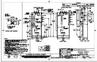
2.2.7 Wiring for 1600 A and 3200 A Models<br />
CHAPTER 2: INSTALLATION<br />
For the 1600 A and 3200 A models (order codes PL1000***SP162* and PL1000***SP322*),<br />
the CT terminations are made on the HCA-2 module to allow the EPM 1000 to accept 5 A<br />
secondary current inputs. CAREFULLY observe the following figure and terminate the CT<br />
leads on the included HCA-2 module, NOT the fuse block.<br />
709717A1.CDR<br />
FIGURE 2–6: CT Terminations for 1600 A and 3200 A Models<br />
2–8 EPM 1000 SUB-METER – INSTRUCTION MANUAL
CHAPTER 2: INSTALLATION<br />
2.3 Installation of <strong>Meter</strong> and Current Transformers<br />
Note<br />
2.3.1 Procedure<br />
The use of the following procedure is mandatory. Certification requires a visual inspection<br />
of the current transformers and the voltage taps on the incoming feeder phase wires.<br />
Mount the back box to the wall, or in the wall for flush mount<br />
installations.<br />
Connect the breaker panel box to the back box of the meter with a<br />
metal conduit through which the 3 or 4 feeder phase taps and the 6<br />
CT wires will be run.<br />
Make sure to use at least a ¾-inch ID conduit to allow for all 9 or 10<br />
wires to pass easily.<br />
Locate the incoming feeder phase (hot) wires at the top of the<br />
breaker panel.<br />
Tape the incoming feeder wires according to phase with black, red<br />
and blue electrical tape for identification purposes.<br />
Extend the CT wires with AWG #16 stranded with black, red and<br />
blue jackets so as to be the correct length to pass through the<br />
conduit and reach the fuse block in the meter back box.<br />
Extend the white wire of each CT with a white wire, but place a<br />
black, red or blue electrical tape on the end of the extended wire to<br />
identify the correct neutral.<br />
Refer to these CT white wires with tape as white/black, white/red<br />
and white/blue respectively.<br />
Remove the incoming feeder hot wires one at a time and place<br />
each CT over the proper feeder wire.<br />
Make sure that the colors of the CT leads correspond to the color of<br />
the tape on the phase feeder.<br />
Make certain that the white wire from the CT is closest to the line<br />
side of the feed, away from the top of the breaker panel.<br />
For split-core CTs, make sure that the X1 is toward the line side.<br />
Run the CT secondary wires through conduit to the back box of the<br />
meter.<br />
Tap the three feeder wires with AWG #12 stranded wire with black,<br />
red and blue jackets taking care to match the color of the<br />
insulation of the #12 wires to correspond to the color of the tape on<br />
the feeder wire.<br />
If the service is 4-wire, tap the neutral connection with a #12 AWG<br />
stranded wire with a white jacket.<br />
Run the six (6) current transformer wires black, white/black, red,<br />
white/red and blue, white/blue to IA+, NA–, IB+, NB–, IC+, NC–<br />
respectively on the fuse block (see Internal Fuse Block on page 2–<br />
11).<br />
EPM 1000 SUB-METER – INSTRUCTION MANUAL 2–9
CHAPTER 2: INSTALLATION<br />
Take the black, red, blue and white (if available) #12 AWG feeder<br />
phase tap wires and run them to ⇔A, ⇔B, ⇔C, and N (if available)<br />
respectively (see Internal Fuse Block on page 2–11).<br />
Plug the fuse block into the meter head and hang the meter head<br />
on the back box.<br />
Close up the breaker panel until the certification inspector arrives.<br />
2–10 EPM 1000 SUB-METER – INSTRUCTION MANUAL
CHAPTER 2: INSTALLATION<br />
2.3.2 Internal Shorting Terminal<br />
FIGURE 2–7: Internal Fuse Block<br />
709721A1.CDR<br />
EPM 1000 SUB-METER – INSTRUCTION MANUAL 2–11
2.4 Installing the Pulse Inputs<br />
2.4.1 Pulse Input Option<br />
CHAPTER 2: INSTALLATION<br />
The EPM 1000 with the Pulse Input option will provide a 5-wire harness from the back of<br />
the meter head. The color coding on the harness is as follows and the M# and Q# refers to<br />
meter registers that will appear if the meter has pulse inputs:<br />
• COMMON (WHITE)<br />
• M2 Q14 (GREEN)<br />
• M2 Q13 (ORAN<strong>GE</strong>)<br />
• M1 Q14 (RED)<br />
• M1 Q13 (BLACK)<br />
2–12 EPM 1000 SUB-METER – INSTRUCTION MANUAL
CHAPTER 2: INSTALLATION<br />
2.5 Installing the <strong>GE</strong> Transponder<br />
2.5.1 Procedure<br />
If your application is for a metering system, use the following procedure to install the<br />
transponder.<br />
Plan for the transponders.<br />
• Determine the number of services in order to determine the<br />
number of transponders. Do not rely solely on the memory of the<br />
local engineers or of the existing drawings. Drawings may not<br />
have been properly updated to reflect as-built conditions and<br />
memories are not always accurate. Use these as guidelines and<br />
then perform a survey. Open electrical cabinets as necessary and<br />
locate every master meter from the utility.<br />
• Make careful note of the voltages of the various transponders.<br />
Determine the number of tenant spaces.<br />
• In residential applications, this number should be fixed. Often<br />
apartments are laid out on a grid, such as by floor and by line. In<br />
this case, the number of meters is simply the number of floors<br />
times the number of lines. This information is needed before any<br />
meters are installed or entered into the transponders.<br />
• Determine which service feeds each metering point. This<br />
information is vital to proper system operation. Without this<br />
information, a laborious process of trial and error is necessary to<br />
determine which transponder must be used for each meter. This<br />
will increase the cost of certification and commissioning of the<br />
system.<br />
Determine the service size and type of meter for each metering<br />
point.<br />
• In residential applications, this is probably a constant amperage<br />
across the entire job (either 50A or 100A with Series 10 meters).<br />
Determine the number of telephone lines required and ensure the<br />
lines are installed before the installation of any metering<br />
equipment.<br />
Determine the number of independent services.<br />
• Typically there is one service per distribution transformer that<br />
feeds the property, unless distribution transformers have parallel<br />
secondaries, which is rare.<br />
Locating the best location for each transponder.<br />
This is the closest point to the first point at which the feeders for the service branch out<br />
into sub-feeders. To find this point, follow the feeders from the secondary of the<br />
distribution transformer (or the service entrance if the transformer is off the property) and<br />
place the transponder at the last point before the feeder breaks into multiple feeders.<br />
EPM 1000 SUB-METER – INSTRUCTION MANUAL 2–13
Note<br />
Note<br />
CHAPTER 2: INSTALLATION<br />
Determine which of the transponders should have a telephone<br />
modem, and order a telephone line to terminate at that point.<br />
Do not proceed with the installation until the telephone line is<br />
installed.<br />
After the telephone line is installed, install the transponder with<br />
the modem next to the telephone line.<br />
Install all three phases and the neutral to the transponder (see<br />
Installation of <strong>Meter</strong> and Current Transformers on page 2–9 for<br />
details).<br />
If there is more than one transponder, install the other<br />
transponders and the interconnecting RS485 line, if required, which<br />
links all of the transponders<br />
(Go directly to Installation of <strong>Meter</strong> and Current Transformers on<br />
page 2–9 if there is only one transponder in the system or if each<br />
transponder in the system has a modem and telephone line<br />
connection).<br />
• An RS485 line is a pair of wires, AWG #20 or larger in diameter,<br />
which begins at one transponder where a terminator is placed.<br />
• The RS485 line runs from transponder to transponder ending at<br />
the final transponder, where another terminator is placed.<br />
It is critically important that there should never be three RS485 pairs entering or<br />
leaving a transponder box.<br />
• For the two transponders which have terminators, only one<br />
RS485 pair leaves each box.<br />
• For the other transponders, if there are more than two, exactly<br />
two RS485 lines should leave the box: each line goes to another<br />
transponder in the daisy-chain.<br />
Only one modem should be installed in a data link system. If there<br />
are two or more modems in a data link system, the transponders<br />
will not communicate with each other.<br />
• There may be no more than 32 transponders on a daisy-chain. If<br />
there are more than 32, special care must be taken, which is<br />
beyond the scope of these instructions.<br />
If possible, run the RS485 lines in a conduit to protect them from<br />
damage.<br />
It is critically important to observe the polarity of the wires. The RS485 data link uses a<br />
black and yellow color code. Match black to black and yellow to yellow; otherwise the<br />
data link will not work.<br />
To test the data link, measure the DC voltage across the yellow to<br />
black wire.<br />
This should measure between 0.1 and 0.3 V. If it is negative or<br />
outside of that range, re-check all of the transponder boxes<br />
according to the above specifications.<br />
2–14 EPM 1000 SUB-METER – INSTRUCTION MANUAL
<strong>GE</strong> Consumer & Industrial<br />
Multilin<br />
3.1 Menu Navigation<br />
EPM 1000 Single Point<br />
<strong>Sub</strong>metering System<br />
Chapter 3: Using the <strong>Meter</strong><br />
Using the <strong>Meter</strong><br />
3.1.1 User Interface<br />
The following figure shows the EPM 1000 user interface located on the front panel of the<br />
meter. It is easy to navigate the various sub-menus to read metering data, reset values and<br />
view configuration data.<br />
FIGURE 3–1: EPM 1000 User Interface<br />
709719A1.CDR<br />
Press and hold the “Display Scroll” button. After two seconds, the LCD will display the<br />
REVERSE message. Two seconds later, the LCD will display FORWARD. Two seconds later,<br />
a different sub-menu register heading as shown on the following page (the top row) in will<br />
be displayed in two-second intervals. Note that the EPM 1000 defaults to the kWh register.<br />
EPM 1000 SUB-METER – INSTRUCTION MANUAL 3–1
CHAPTER 3: USING THE METER<br />
Releasing the display scroll button at a given submenu heading will allow you to cycle<br />
through the registers listed under the selected submenu heading. Pressing and releasing<br />
the display button will advance to the next block of registers in the sub-menu.<br />
To reverse scrolling direction at either the heading level or within a submenu, press and<br />
hold the display scroll button. When REVERSE is displayed after two seconds, release the<br />
display scroll button. You can now go backwards through the menu selections by pressing<br />
and releasing the display scroll button.<br />
To go back to the forward scrolling option, follow the same procedure, except release the<br />
display scroll button when FORWARD is displayed.<br />
3–2 EPM 1000 SUB-METER – INSTRUCTION MANUAL
CHAPTER 3: USING THE METER<br />
FIGURE 3–2: EPM 1000 Display Structure<br />
709720A1.CDR<br />
EPM 1000 SUB-METER – INSTRUCTION MANUAL 3–3
3.2 CT Multiplier Table<br />
Note<br />
Note<br />
3.2.1 CT Multipliers<br />
CHAPTER 3: USING THE METER<br />
The following table MUST BE used to verify the correct current readings, based on the<br />
rating of the CT installed.<br />
Table 3–1: CT Multiplier Table<br />
CT Size Multiplier<br />
50 A × 0.5<br />
100 A × 1<br />
200 A × 2<br />
400 A × 4<br />
800 A × 8<br />
1600 A × 32<br />
3200 A × 64<br />
The multiplier that corresponds with the CT rating MUST BE applied to the current reading<br />
shown on the display of the EPM 1000 by multiplying that reading by the multiplier shown<br />
above. The multiplier MUST also be applied in the same manner when calculating kW and<br />
kWh. Failure to use the appropriate multiplier will result in an incorrect diagnosis of the<br />
meter's functionality and incorrect revenue billing.<br />
3–4 EPM 1000 SUB-METER – INSTRUCTION MANUAL
CHAPTER 3: USING THE METER<br />
3.3 Verifying <strong>Meter</strong> Functionality<br />
Note<br />
3.3.1 Overview<br />
3.3.2 Verifying Voltage<br />
3.3.3 Verifying kWh Reading<br />
Once you have familiarized yourself with the EPM 1000 menu structure, it is critical to verify<br />
that the meter and CTs are properly installed.<br />
To correctly diagnose the meter, there must be loads on all three phases of the meter.<br />
Press and hold the Display Scroll button until the following menu<br />
heading is displayed:<br />
Phase Diagnostic<br />
Registers<br />
Release the Display Scroll button. Scroll down by pressing and<br />
releasing the Display Scroll Button until the following submenu is<br />
displayed:<br />
Volts 125.3 A<br />
124.0 B 124.7 C<br />
Verify that phases A, B and C are displaying voltages; i.e., for a<br />
120 V AC, the reading should be 117 V +10%/–15%.<br />
Press and hold the Display Scroll button until the following menu<br />
heading is displayed:<br />
kWH Registers<br />
Registers<br />
Release the Display Scroll button. Scroll down by pressing and<br />
releasing the Display Scroll button until the following sub-menu is<br />
displayed:<br />
AllHrs kWH<br />
1.046<br />
Verify that the kWh value increases as you view the LCD.<br />
EPM 1000 SUB-METER – INSTRUCTION MANUAL 3–5
3.3.4 Verifying Current and <strong>Energy</strong><br />
CHAPTER 3: USING THE METER<br />
Press and hold the Display Scroll button until the following menu<br />
heading is displayed:<br />
Phase Diagnostic<br />
Registers<br />
Release the Display Scroll button. Scroll down by pressing and<br />
releasing the Display Scroll button until the following submenu is<br />
displayed:<br />
Phase 1 7.468 A<br />
818.7 W 100.5 R<br />
The A(mperage) reading in the display above will always be a positive number, even if the<br />
CT was incorrectly installed. Check the reading to see if it indicates the approximate<br />
current you expected. Remember that this applies to Phase 1 only. If all the numbers on the<br />
multiplier screen were 1.00 and the current transformers are 100:0.1, your multiplier is 1<br />
and the readings are the actual values. If the CTs are 200:0.1, multiply the current reading<br />
by 2.<br />
The W(att) reading will also count forward as your view the LCD. A negative power reading<br />
is indicative of an incorrectly installed CT, or one that is cross-phased with the wrong<br />
voltage (phase) leg. The R(eactive) reading can be negative, depending on the nature of the<br />
load. Negative values indicate a capacitive load while positive values indicate an inductive<br />
load.<br />
Scroll down by pressing and releasing the Display Scroll Button<br />
until the following submenu is displayed:<br />
Ph 1 935.4 VA<br />
6.8° .875 PF<br />
Under normal conditions the phase angle (x.x°) should be close to 0° and the power factor<br />
should be a number close to 1 (one). Resistive loads will have a power factor close to 1,<br />
while inductive loads will typically reflect a power factor between 0.80 to 0.95, or even<br />
lower.<br />
If the phase angle on the lower left is a number close to 180°, it indicates the CT was<br />
installed backwards, or 180° out-of-phase. If the number is close to 120°, at least two CTs<br />
have been cross-phased, and a similar number will appear in the phase angle data in<br />
Phase 2.<br />
To view screens for Phases 2 and 3, repeat the same steps as<br />
above.<br />
3–6 EPM 1000 SUB-METER – INSTRUCTION MANUAL
CHAPTER 3: USING THE METER<br />
3.4 Resetting the Demand Values<br />
3.4.1 Procedure<br />
Use the following procedure to reset the Demand registers to zero:<br />
Press and hold the Demand Reset button.<br />
• The LCD will initially display a copyright message.<br />
• The LCD will then display the Dmdreset event screen:<br />
Dmdreset 1<br />
20:00 06/14/2003<br />
Keep the Demand Reset button depressed until the screen updates<br />
and displays the current date and time. This signifies that the<br />
demand has been reset.<br />
EPM 1000 SUB-METER – INSTRUCTION MANUAL 3–7
CHAPTER 3: USING THE METER<br />
3–8 EPM 1000 SUB-METER – INSTRUCTION MANUAL
<strong>GE</strong> Consumer & Industrial<br />
Multilin<br />
4.1 Modbus Communications<br />
4.1.1 RS485 Wiring for Modbus<br />
EPM 1000 Single Point<br />
<strong>Sub</strong>metering System<br />
Chapter 4: Communications<br />
Communications<br />
The wiring for Modbus communications for two-wire and four-wire RS485 is indicated<br />
below.<br />
For two-wire RS-485:<br />
For four-wire RS-485:<br />
Color Function DB-9 Pinout<br />
Yellow RX (+) 2<br />
Black TX (–) 8<br />
Color Function DB-9 Pinout<br />
Yellow (A) RX (+) 2<br />
Black (B) RX (–) 3<br />
Green (Y) TX (+) 7<br />
Red (Z) TX (–) 8<br />
709725A1.CDR<br />
FIGURE 4–1: RS-485 Serial Connections<br />
EPM 1000 SUB-METER– INSTRUCTION MANUAL 4–1
Note<br />
4.1.2 RS232 Wiring for Modbus<br />
4.1.3 Modbus Commands<br />
CHAPTER 4: COMMUNICATIONS<br />
The EPM 1000 optical port is disabled for units with 2-wire RS485 connections.<br />
The wiring for Modbus communications for RS232 is indicated below.<br />
The EPM 1000 is capable of acting as a remote slave unit to a Modbus master device via<br />
modem, RS232, RS485, or PLC. Up to 32 EPM 1000 meters (or other RS485 devices) can be<br />
daisy-chained together on a single LAN.<br />
The EPM 1000 communicates at a default baud rate of 19200, with no parity and 1 stop bit.<br />
The default Modbus address is 100. Changes to the default baud rate or address can be<br />
accomplished through the configuration file upload.<br />
The following Modbus commands are supported by the EPM 1000:<br />
• 03: Read R4 type register(s)<br />
• 06: Write single register; address “0” is used as the broadcast address<br />
• 16: Write multiple registers; address “0” is used as the broadcast address<br />
4.1.4 Fixed Modbus Values<br />
The EPM 1000 provides fixed register values indicating the meter's serial number, the<br />
meter's version number, and the Modbus addresses.<br />
4.1.5 Modbus Data Register (R4 Type) Groups<br />
Color Function DB-9 Pinout<br />
Black TX 2<br />
Red RX 3<br />
Green GND 5<br />
The EPM 1000 has divided the supported register map (see following pages) into the<br />
following register groups for various fixed and dynamic data values:<br />
• Setup Information<br />
• Interval<br />
• Average Interval Data<br />
• Instantaneous Data<br />
• Three-Phase Data<br />
• Real Time Data<br />
• <strong>Meter</strong> Configuration Data<br />
The EPM 1000 provides access to stored-interval data channels via Modbus command. The<br />
data items as defined in the following register map are based on default data channels<br />
that include the following 3-phase-totaled values (interval average) per meter:<br />
4–2 EPM 1000 SUB-METER– INSTRUCTION MANUAL
CHAPTER 4: COMMUNICATIONS<br />
• Real Power in kW<br />
• Reactive Power in kvar<br />
• Apparent Power in kVA<br />
• Power Factor<br />
4.1.6 Instantaneous Data Items<br />
Data is logged per the configurable time interval value. The default log interval is 15<br />
minutes.<br />
The Modbus master can request stored interval data by writing the interval date and time<br />
to the appropriate registers and by setting the data status register to 1. Upon the data<br />
ready flag (address 67) being written to 1, the interval data registers (addresses 100 to 107)<br />
are simultaneously updated with the appropriate values for the requested interval. The<br />
data ready flag returns a 0 for “data is ready”, or “2” for “invalid time interval requested.”<br />
The EPM 1000 also provides registers that constantly hold the oldest stored-interval<br />
(addresses 58 to 60) and most recent stored-interval time and date stamps (addresses 61<br />
to 63).<br />
The EPM 1000 provides registers for per-phase instantaneous values (see below).<br />
Instantaneous register values are updated once per second.<br />
• Frequency<br />
• Total Harmonic Distortion (% for volts)<br />
• Voltage<br />
• Current<br />
• Real Power in kW<br />
• Reactive Power in kvar<br />
• Apparent Power in kVA<br />
The EPM 1000 provides one-second updated inputs, including the following 3-phasetotaled<br />
values per 3-phase-meter:<br />
• <strong>Energy</strong>: kWh and kvarh<br />
• Power: kW, kvar, and kVA<br />
• Power Factor<br />
4.1.7 32-bit Long and Float Data Formats<br />
The EPM 1000 supports standard format for 32-bit Long (signed or unsigned). The first of<br />
the two 16-bit Modbus register set contains the HIGH order 16 bits of the 32-bit Long data.<br />
The second of the two 16-bit Modbus register set contains the LOW order 16 bits of the 32bit<br />
Long data.<br />
The EPM 1000 supports Intel 32 bit (IEEE) FLOAT format. That means, unlike the standard<br />
Long format, the first of the two 16-bit Modbus register set contains the LOW order 16 bits<br />
of the 32-bit Float data. The second of the two 16-bit Modbus register set contains the<br />
HIGH order 16 bits of the 32-bit Float data.<br />
EPM 1000 SUB-METER– INSTRUCTION MANUAL 4–3
4.2 Modbus Activation<br />
Note<br />
4.2.1 Overview<br />
CHAPTER 4: COMMUNICATIONS<br />
The EPM 1000 is shipped with Modbus not activated. To activate the Modbus protocol, it is<br />
necessary to use the Hilgraeve HyperTerminal Private Edition software. This software is<br />
available from the following website:<br />
http://www.hilgraeve.com/htpe<br />
Once Modbus is activated, the meter will ignore the following ASCII commands unless the<br />
login string is sent using the “Key Macros” function within HyperTerminal. Set up “Key<br />
Macros” to send the login string (see Logging into the <strong>Meter</strong> on page 4–5) followed by<br />
[ENTER].<br />
The login string must be sent without breaking up packets.<br />
A direct connection from a serial port to the EPM 1000 RS485 port (via RS232/485<br />
converter) is highly recommended. <strong>GE</strong>'s Ethernet Gateway will break up this login string<br />
into packets and prevent login.<br />
The EPM 1000 only allows login at 9600, 19200 or 38400 baud when NOT in Modbus mode.<br />
This is displayed as HUNT in the meter display under Serial # Registers. Once in Modbus,<br />
the EPM 1000 only responds at the programmed baud rate.<br />
4.2.2 Configuring a New HyperTerminal Session<br />
Use the following procedure to configure a new HyperTerminal session.<br />
Enter the New Connection Name.<br />
Select the COM port to connect to the meter.<br />
Select the COM port properties.<br />
The following window will appear – use the setting shown below.<br />
Select the File > Properties > Settings > ASCII Setup menu item.<br />
4–4 EPM 1000 SUB-METER– INSTRUCTION MANUAL
CHAPTER 4: COMMUNICATIONS<br />
4.2.3 Confirming Connection to the EPM 1000<br />
Check the Echo typed characters locally option, as shown below.<br />
To confirm a proper RS485 connection to the EPM 1000, enter the<br />
following command:<br />
attn -D (followed by the [ENTER] key)<br />
If meter is properly connected, it will respond with a serial number and poll<br />
address. Once in Modbus mode, this command will no longer work.<br />
For example, entering the command<br />
attn -D<br />
followed by the [ENTER] key returns:<br />
60005866 256<br />
for a meter with serial number 60005866 and poll address 256.<br />
4.2.4 Logging into the <strong>Meter</strong><br />
Use the following procedure to login to the EPM 1000.<br />
Setup a ‘key macro’ in HyperTerminal by selecting the View > Key<br />
Macros menu item.<br />
Click New and select an appropriate macro key sequence (ALT-1 is<br />
used the example below.<br />
Enter the following command in the Action area:<br />
attn -S[serialNumber] -5lEvElbAl<br />
The password is -s5 followed by the LABLEVEL text spelled<br />
backwards, with the vowels in upper case. This login string must<br />
be followed by the ENTER command within the key macro.<br />
For example, for a unit with serial number 60005866, enter the<br />
following text:<br />
EPM 1000 SUB-METER– INSTRUCTION MANUAL 4–5
4.2.5 Activating Modbus Communications<br />
Use the following procedure to activate Modbus communications.<br />
CHAPTER 4: COMMUNICATIONS<br />
Enter the following command to activate Modbus:<br />
stty -M1 (followed by [ENTER] twice)<br />
Select the baud rate by entering the following command.<br />
The baud rate options for Modbus communication are 9600, 19200,<br />
and 38400.<br />
stty 19200 (followed by [ENTER] twice)<br />
Save Modbus activation by entering:<br />
stty -W1234<br />
Display Modbus activation by entering:<br />
stty<br />
This command displays meter port setting, baud rate, etc. If Modbus is active, it returns<br />
“Modbus”; if Modbus is not active, it returns “no Modbus”.<br />
For example, consider the following set of commands sets the activates Modbus, sets the<br />
baud rate to 19200, and saves the Modbus activation. The text returned by the meter is<br />
also indicated.<br />
CIP#stty<br />
hunt 19200 baud 8 bits no parity no echo no modem no<br />
modbus<br />
CIP#stty -M1<br />
CIP#stty 19200<br />
CIP#stty -W1234<br />
CIP#stty<br />
hold 19200 baud 8 bits no parity no echo no modem modbus<br />
4–6 EPM 1000 SUB-METER– INSTRUCTION MANUAL
CHAPTER 4: COMMUNICATIONS<br />
Note<br />
4.2.6 Changing Modbus Settings<br />
4.2.7 Logging Out<br />
Use the following procedure to change the Modbus address setting:<br />
Enter the following command to set the Modbus address:<br />
attn -p#<br />
where # is replaced by the actual address desired (for example, attn -p100).<br />
Save the Modbus address as follows<br />
attn -W1234<br />
Enter the following command to display and verify the Modbus<br />
address:<br />
attn -d<br />
This command displays the meter serial number and the poll/Modbus number.<br />
Use one of the following commands to logout of the meter:<br />
attn or exit<br />
Once Modbus is set, it is best to type [HALT] followed by [ENTER] or cycle power to the<br />
meter. Otherwise, Modbus will become active one minute after logout.<br />
To log into meter once Modbus is active, use hot keys to program the login sequence. The<br />
login sequence must include either the serial number or the Modbus address.<br />
Example hot key sequences are shown below:<br />
attn -S60005866 -3Super3<br />
attn 256 -3Super3<br />
4.2.8 Disabling Modbus Communications<br />
Use the following procedure to disable Modbus communications:<br />
Turn off Modbus with the following command:<br />
stty -M0<br />
Save Modbus settings:<br />
stty -W1234<br />
EPM 1000 SUB-METER– INSTRUCTION MANUAL 4–7
4.3 Modbus Memory Map<br />
4.3.1 Memory Map<br />
The Modbus memory map is shown below.<br />
Hex<br />
Addr<br />
Table 4–1: Modbus Memory Map (Sheet 1 of 4)<br />
CHAPTER 4: COMMUNICATIONS<br />
Addr Description R/W Units Notes<br />
Fixed Value Registers (Read Only)<br />
0000 + 0000 <strong>Meter</strong> Serial Number R 32-bit long integer<br />
0002 + 0002 <strong>Meter</strong> Serial Number Extension R<br />
Returns same value as address 0000<br />
32-bit long integer<br />
0004 + 0004 <strong>Meter</strong> Version Number R 32-bit long integer<br />
0006 + 0006 <strong>Meter</strong> Version Number Extension R<br />
Returns same value as address 0000<br />
32-bit long integer<br />
0008 0008 <strong>Meter</strong> Modbus Address R --- 8-bit Modbus Address in LSB<br />
Setup Information<br />
0009 0009 Baud Rate R<br />
000C 0012 <strong>Meter</strong> Status R --- Always 1 for Modbus.<br />
000D 0013 <strong>Meter</strong> Ready R --- Always 1 for Modbus.<br />
000E 0014 Number of <strong>Meter</strong>s Configured R --- Always 1 for EPM 1000<br />
000F 0015<br />
0010 0016<br />
0011 0017<br />
0012 0018<br />
0013 0019<br />
0014 0020<br />
Interval Setup<br />
Number of Real-Time Points<br />
Configured<br />
Number of Interval Points<br />
Configured<br />
Number of Max/Min Points<br />
Configured<br />
Maximum Number of Intervals<br />
That Can Be Recorded<br />
Number of slots configured for<br />
Transponder<br />
Current slot being read in<br />
Transponder<br />
4–8 EPM 1000 SUB-METER– INSTRUCTION MANUAL<br />
R<br />
R Returns 0 if intervals are disabled<br />
R Always returns 0<br />
R<br />
R<br />
R/W<br />
0031 0049 Store Interval Length R/W minutes<br />
Read Clock<br />
0032 0050 Internal Time - Hours/Minutes R/W hours/<br />
minutes<br />
0033 0051 Internal Time - Seconds R/W seconds<br />
0034 0052 Internal Date - Month/Day R/W month/day<br />
0035 0053 Interval Date - Year R/W year<br />
Dependent upon the number of<br />
parameters optioned and the number of<br />
meters returned in address 0015<br />
Interval length in minutes must be evenly<br />
divisible into 60 (1, 2, 3, 4, 5, 6, 10, 12, 15,<br />
20, 30, 60)<br />
16-bit, Hours: 0-23 (bitmask = FF00)<br />
Minutes: 0-59 (bitmask = 00FF
CHAPTER 4: COMMUNICATIONS<br />
Hex<br />
Addr<br />
0036 0054 Internal Time - Hours/Minutes R/W hours/<br />
minutes<br />
0037 0055 Internal Time - Seconds R/W month/day<br />
16-bit, Hours: 0-23 (bitmask = FF00)<br />
Minutes: 0-59 (bitmask = 00FF<br />
0038 0056 Internal Date - Month/Day R/W Year 16-bit Unsigned Integer<br />
0039 0057 Interval Date - Year R/W 16-bit Unsigned Integer<br />
003A 0058<br />
003B 0059<br />
Date/Time of Oldest Interval -<br />
Hours/Minutes<br />
Date/Time of Oldest Interval -<br />
Month/Day<br />
R/W Hours/<br />
Minutes<br />
R/W Month/Day<br />
16-bit, Hours: 0-23 (bitmask = FF00)<br />
Minutes: 0-59 (bitmask = 00FF)<br />
DDE Data is COM Compatible,<br />
Date/Time Numeric<br />
16-bit<br />
Month: 1=Jan., 12=Dec. (bitmask = FF00)<br />
Day: 1-31 (bitmask = 00FF)<br />
DDE Data is COM Compatible,<br />
Date/Time Numeric<br />
003C 0060 Date/Time of Oldest Interval - Year R/W Year 16-bit Unsigned Integer<br />
003D 0061<br />
003E 0062<br />
003F 0063<br />
0040 0064<br />
0041 0065<br />
0042 0066<br />
Date/Time of Newest Interval -<br />
Hours/Minutes<br />
Date/Time of Newest Interval -<br />
Month/Day<br />
Date/Time of Newest Interval -<br />
Year<br />
Date/Time of Currently Selected<br />
Interval - Hours/Minutes<br />
Date/Time of Currently Selected<br />
Interval - Month/Day<br />
Date/Time of Currently Selected<br />
Interval - Year<br />
0043 0067 Data Ready Flag R/W<br />
3-Phase Totaled Values<br />
0063 0099 Interval Data Qualifying Register R<br />
R/W Hours/<br />
Minutes<br />
R/W Month/Day<br />
16-bit, Hours: 0-23 (bitmask = FF00)<br />
Minutes: 0-59 (bitmask = 00FF)<br />
16-bit<br />
Month: 1=Jan., 12=Dec. (bitmask = FF00)<br />
Day: 1-31 (bitmask = 00FF)<br />
DDE Data is COM Compatible,<br />
Date/Time Numeric<br />
R/W Year 16 Bit Unsigned Integer<br />
R/W Hours/<br />
Minutes<br />
R/W Month/Day<br />
16-bit, Hours: 0-23 (bitmask = FF00)<br />
Minutes: 0-59 (bitmask = 00FF<br />
16-bit<br />
Month: 1=Jan., 12=Dec. (bitmask = FF00)<br />
Day: 1-31 (bitmask = 00FF)<br />
DDE Data is COM Compatible,<br />
Date/Time Numeric<br />
R/W Year 16 Bit Unsigned Integer<br />
0064 0100 3-Phase Totaled kW R kW Stored Interval 1<br />
0066 0102 3-Phase Totaled kvar R kvar Stored Interval 2<br />
0068 0104 3-Phase Totaled kVA R kVA Stored Interval 3<br />
006A 0106 3-Phase Totaled Power Factor R % Stored Interval 4<br />
<strong>Meter</strong>ed Values<br />
Table 4–1: Modbus Memory Map (Sheet 2 of 4)<br />
Addr Description R/W Units Notes<br />
16 Bits: Mask out/ignore Bit 15.<br />
0=Data is ready for read<br />
1=Populate registers with timestamp<br />
data<br />
2=Invalid Timestamp Requested<br />
Stored Dynamic Data Ready for Read<br />
16-bit Unsigned Integer, 8 = Invalid<br />
Interval<br />
0162 0354 Frequency (Phase A) R Hz Instantaneous Frequency<br />
016A 0362 Voltage (A-N) R V Instantaneous Voltage<br />
016C 0364 Voltage (B-N) R V Instantaneous Voltage<br />
016E 0366 Voltage (C-N) R V Instantaneous Voltage<br />
EPM 1000 SUB-METER– INSTRUCTION MANUAL 4–9
Hex<br />
Addr<br />
CHAPTER 4: COMMUNICATIONS<br />
0170 * 0368 Voltage (CT01) R V Instantaneous Voltage<br />
0172* 0370 Amps (CT01) R A Instantaneous Current<br />
0174* 0372 kW (CT01) R kW Instantaneous Power<br />
0176* 0374 kvar (CT01) R kvar Instantaneous Reactive Power<br />
0178* 0376 kVA (CT01) R kVA Instantaneous Apparent Power<br />
017A* 0378 Voltage (CT02) R V Instantaneous Voltage<br />
017C* 0380 Amps (CT02) R A Instantaneous Current<br />
017E* 0382 kW (CT02) R kW Instantaneous Power<br />
0180* 0384 kvar (CT02) R kvar Instantaneous Reactive Power<br />
0182* 0386 kVA (CT02) R kVA Instantaneous Apparent Power<br />
0184* 0388 Voltage (CT03) R V Instantaneous Voltage<br />
0186* 0390 Amps (CT03) R A Instantaneous Current<br />
0188* 0392 kW (CT03) R kW Instantaneous Power<br />
018A* 0394 kvar (CT03) R kvar Instantaneous Reactive Power<br />
018C* 0396 kVA (CT03) R kVA Instantaneous Apparent Power<br />
Three-Phase <strong>Meter</strong>ed Values<br />
0288* 0648 3-Phase kWh R kWh Real Time Input 1<br />
028A* 0650 3-Phase kvarh R kvarh Real Time Input 2<br />
028C* 0652 3-Phase kW R kW Real Time Input 3<br />
028E* 0654 3-Phase kvar R kvar Real Time Input 4<br />
0290* 0656 3-Phase kVA R kVA Real Time Input 5<br />
0292* 0658 3-Phase Power Factor R % Real Time Input 6<br />
Total Harmonic Distortion (THD)<br />
03E8* 1000 THD Phase A R % Total Harmonic Distortion<br />
03EA* 1002 Phase Angle A R degrees Phase Angle<br />
03EC* 1004 Phase-to-Phase Voltage A R V Instantaneous Voltage<br />
03EE* 1006 THD Phase B R % Total Harmonic Distortion<br />
03F0* 1008 Phase Angle B R degrees Phase Angle<br />
03F2* 1010 Phase-to-Phase Voltage B R V Instantaneous Voltage<br />
03F4* 1012 THD Phase C R % Total Harmonic Distortion<br />
03F6* 1014 Phase Angle C R degrees Phase Angle<br />
03F8* 1016 Phase-to-Phase Voltage C R V Instantaneous Voltage<br />
Counters<br />
07D0 2000 Number of phases offset<br />
Table 4–1: Modbus Memory Map (Sheet 3 of 4)<br />
Addr Description R/W Units Notes<br />
16-bit Unsigned Integer<br />
1, 2, 3, or 24 phases available<br />
4–10 EPM 1000 SUB-METER– INSTRUCTION MANUAL
CHAPTER 4: COMMUNICATIONS<br />
Note<br />
Hex<br />
Addr<br />
07D1 2001 Demand Window Offset<br />
07D2 2002 I Multiplier Type Offset<br />
07D3 2003 Number of Pulse Counters Offset<br />
07D4 2004 Overlap Offset<br />
07D5 2005 Number TOU's Offset<br />
Table 4–1: Modbus Memory Map (Sheet 4 of 4)<br />
Addr Description R/W Units Notes<br />
16-bit Unsigned Integer<br />
5, 15, or 30 minutes available<br />
16-bit Unsigned Integer<br />
Internal calibration value<br />
1. 32-bit floating point numbers are as per the IEEE 754-1985 standard.<br />
16-bit Unsigned Integer<br />
Number of external pulse inputs installed<br />
16-bit Unsigned Integer<br />
Number of adjacent demand windows<br />
that are averaged to determine peak<br />
demand<br />
16-bit Unsigned Integer<br />
Number of different TOU periods defined<br />
in the time-of-use table<br />
07D6 2006 MDT_M_TABLE_REG_START 16-bit Unsigned Integer<br />
07D7 2007 NUM_MDT_M_TABLE_COLUMNS 16-bit Unsigned Integer<br />
07D8 2008 NUM_MDT_M_TABLE_REGS 16-bit Unsigned Integer<br />
07D9 2009 MDT_M_TABLE_REG_END 16-bit Unsigned Integer<br />
* 32-bit floating point register.<br />
+ 32-bit long integer - Range: 00000000h to FFFFFFFFh<br />
2. Registers 0X0063 to 0X025E are all read-only and cannot be modified. They break<br />
down as follows:<br />
• Registers 0X0064 to 0X0122 are not real-time, but are populated with<br />
stored interval data based on user inputs to registers 0X0040 to 0X0043.<br />
• Registers 0X0162 to 0X025E are all real-time data registers.<br />
EPM 1000 SUB-METER– INSTRUCTION MANUAL 4–11
CHAPTER 4: COMMUNICATIONS<br />
4–12 EPM 1000 SUB-METER– INSTRUCTION MANUAL
<strong>GE</strong> Consumer & Industrial<br />
Multilin<br />
5.1 Revision History<br />
EPM 1000 Single Point<br />
<strong>Sub</strong>metering System<br />
Chapter 5: Miscellaneous<br />
Miscellaneous<br />
5.1.1 Release Dates<br />
5.1.2 Changes to the Manual<br />
Table 5–1: Release Dates<br />
MANUAL <strong>GE</strong> PART NO. EPM 1000<br />
REVISION<br />
RELEASE DATE<br />
<strong>GE</strong>K-106554 1601-0155-A1 1.0x 21 May 2004<br />
<strong>GE</strong>K-106554A 1601-0155-A2 1.0x 20 October 2004<br />
<strong>GE</strong>K-106554B 1601-0155-A3 1.0x 1 December 2004<br />
<strong>GE</strong>K-106554C 1601-0155-A4 1.0x 14 February 2005<br />
<strong>GE</strong>K-106554D 1601-0155-A5 1.0x 08 April 2005<br />
<strong>GE</strong>K-106554E 1601-0155-A6 1.0x 30 June 2006<br />
<strong>GE</strong>K-106554F 1601-0155-A7 1.0x 15 November 2007<br />
PA<strong>GE</strong><br />
(A6)<br />
PA<strong>GE</strong><br />
(A7)<br />
Table 5–2: Major Updates for 1601-0155-A7 (Sheet 1 of 2)<br />
CHAN<strong>GE</strong> DESCRIPTION<br />
Title Title Update Manual part number to 1601-0155-A7<br />
EPM 1000 SUB-METER – INSTRUCTION MANUAL 5–1
PA<strong>GE</strong><br />
(A6)<br />
CHAPTER 5: MISCELLANEOUS<br />
3-5 3-6 Update Text change re on-screen copyright statement<br />
4-7 4-8 Update Changes to Modbus Memory Map<br />
PA<strong>GE</strong><br />
(A5)<br />
PA<strong>GE</strong><br />
(A6)<br />
Table 5–3: Major Updates for 1601-0155-A6<br />
CHAN<strong>GE</strong> DESCRIPTION<br />
Title Title Update Manual part number to 1601-0155-A6<br />
4-1 4-1 Update Updated RS485 WIRING FOR MODBUS section<br />
4-2 4-2 Add Added RS232 WIRING FOR MODBUS section<br />
PA<strong>GE</strong><br />
(A4)<br />
PA<strong>GE</strong><br />
(A5)<br />
Table 5–4: Major Updates for 1601-0155-A5<br />
CHAN<strong>GE</strong> DESCRIPTION<br />
Title Title Update Manual part number to 1601-0155-A5<br />
4-3 4-3 Update Updated MODBUS ACTIVATION section<br />
PA<strong>GE</strong><br />
(A3)<br />
PA<strong>GE</strong><br />
(A4)<br />
Table 5–5: Major Updates for 1601-0155-A4<br />
CHAN<strong>GE</strong> DESCRIPTION<br />
Title Title Update Manual part number to 1601-0155-A4<br />
--- 4-1 Add Added RS485 WIRING FOR MODBUS section<br />
PA<strong>GE</strong><br />
(A2)<br />
PA<strong>GE</strong><br />
(A7)<br />
PA<strong>GE</strong><br />
(A3)<br />
Table 5–2: Major Updates for 1601-0155-A7 (Sheet 2 of 2)<br />
CHAN<strong>GE</strong> DESCRIPTION<br />
Table 5–6: Major Updates for 1601-0155-A3<br />
CHAN<strong>GE</strong> DESCRIPTION<br />
Title Title Update Manual part number to 1601-0155-A3<br />
4-3 4-3 Update Updated MODBUS ACTIVATION section<br />
5–2 EPM 1000 SUB-METER – INSTRUCTION MANUAL
CHAPTER 5: MISCELLANEOUS<br />
PA<strong>GE</strong><br />
(A1)<br />
PA<strong>GE</strong><br />
(A2)<br />
Table 5–7: Major Updates for 1601-0155-A2<br />
CHAN<strong>GE</strong> DESCRIPTION<br />
Title Title Update Manual part number to 1601-0155-A2<br />
1-3 1-3 Update Updated OPERATING SPECIFICATIONS<br />
--- 2-7 Add<br />
2-8 2-8 Update<br />
Added CT TERMINATIONS FOR 1600 A AND 3200 A<br />
MODELS diagram<br />
Updated INTERNAL SHORTING TERMINAL diagram<br />
and renamed to INTERNAL FUSE BLOCK<br />
--- 4-1 Add Added MODBUS COMMUNICATIONS chapter<br />
EPM 1000 SUB-METER – INSTRUCTION MANUAL 5–3
5.2 Warranty<br />
5.2.1 <strong>GE</strong> Multilin Warranty<br />
CHAPTER 5: MISCELLANEOUS<br />
General Electric Multilin (<strong>GE</strong> Multilin) warrants each device it manufactures to be free from<br />
defects in material and workmanship under normal use and service for a period of 24<br />
months from date of shipment from factory.<br />
In the event of a failure covered by warranty, <strong>GE</strong> Multilin will undertake to repair or replace<br />
the device providing the warrantor determined that it is defective and it is returned with all<br />
transportation charges prepaid to an authorized service centre or the factory. Repairs or<br />
replacement under warranty will be made without charge.<br />
Warranty shall not apply to any device which has been subject to misuse, negligence,<br />
accident, incorrect installation or use not in accordance with instructions nor any unit that<br />
has been altered outside a <strong>GE</strong> Multilin authorized factory outlet.<br />
<strong>GE</strong> Multilin is not liable for special, indirect or consequential damages or for loss of profit or<br />
for expenses sustained as a result of a device malfunction, incorrect application or<br />
adjustment.<br />
For complete text of Warranty (including limitations and disclaimers), refer to <strong>GE</strong> Multilin<br />
Standard Conditions of Sale.<br />
5–4 EPM 1000 SUB-METER – INSTRUCTION MANUAL
INDEX<br />
Index<br />
A<br />
EPM 1000 SUB-METER– INSTRUCTION MANUAL<br />
APPLICATIONS ...............................................................................................1-2<br />
B<br />
C<br />
CATALOG NUMBERS ......................................................................................1-7<br />
CHAN<strong>GE</strong>S TO MANUAL ................................................................... 5-1, 5-2, 5-3<br />
COMMUNICATIONS<br />
activating Modbus communications ................................................................4-6<br />
memory map .................................................................................................4-8<br />
Modbus.........................................................................................................4-2<br />
Modbus data groups ......................................................................................4-2<br />
CT INSTALLATION ..........................................................................................2-9<br />
CT MULTIPLIERS ............................................................................................3-4<br />
CURRENT TRANSFORMER INSTALLATION ....................................................2-9<br />
CURRENT, VERIFYING ...................................................................................3-6<br />
D<br />
DEMAND, RESETTING ....................................................................................3-7<br />
DESCRIPTION ................................................................................................1-1<br />
DIMENSIONS ..................................................................................................1-5<br />
DISPLAY STRUCTURE....................................................................................3-3<br />
E<br />
ENERGY, VERIFYING .....................................................................................3-6<br />
ENVIRONMENTAL SPECIFICATIONS ..............................................................1-5<br />
F<br />
G<br />
<strong>GE</strong>TTING STARTED ........................................................................................1-1<br />
H<br />
I<br />
INSTALLATION ....................................................................................... 2-1, 2-9<br />
INSTALLATION CATEGORY ............................................................................1-5<br />
INTERIOR VIEW..............................................................................................1-3<br />
INTERNAL FUSE BLOCK...............................................................................2-11
J-L<br />
M<br />
MENU NAVIGATION ....................................................................................... 3-1<br />
MENU STRUCTURE ....................................................................................... 3-3<br />
METER INSTALLATION .................................................................................. 2-9<br />
METERING SYSTEM REQUIREMENTS ........................................................... 2-1<br />
MODBUS<br />
activating ..................................................................................................... 4-6<br />
commands.................................................................................................... 4-2<br />
data register groups ..................................................................................... 4-2<br />
memory map ................................................................................................ 4-8<br />
wiring ........................................................................................................... 4-1<br />
N<br />
O<br />
ORDER CODES.............................................................................................. 1-7<br />
P<br />
POLLUTION DEGREE..................................................................................... 1-5<br />
PREVENTIVE MAINTENANCE ........................................................................ 1-4<br />
PROTECTIVE CONDUCTOR TERMINAL ......................................................... 1-4<br />
PULSE INPUTS ............................................................................................ 2-12<br />
Q<br />
R<br />
RS232 WIRING FOR MODBUS........................................................................ 4-2<br />
RS485 WIRING FOR MODBUS........................................................................ 4-1<br />
S<br />
SCAN TRANSPONDER<br />
functionality.................................................................................................. 1-2<br />
installing .................................................................................................... 2-13<br />
location ...................................................................................................... 2-13<br />
SPECIFICATIONS........................................................................................... 1-5<br />
T<br />
TRANSIENT/SUR<strong>GE</strong> SUPRESSION ................................................................ 1-5<br />
U<br />
USER INTERFACE ......................................................................................... 3-1<br />
INDEX<br />
EPM 1000 SUB-METER– INSTRUCTION MANUAL
INDEX<br />
EPM 1000 SUB-METER– INSTRUCTION MANUAL<br />
V<br />
VERIFYING CURRENT ....................................................................................3-6<br />
VERIFYING ENERGY ......................................................................................3-6<br />
VERIFYING METER FUNCTIONALITY .............................................................3-5<br />
VERIFYING VOLTA<strong>GE</strong>.....................................................................................3-5<br />
VOLTA<strong>GE</strong>, VERIFYING....................................................................................3-5<br />
W<br />
WARNINGS .....................................................................................................1-3<br />
WARRANTY ....................................................................................................5-4<br />
WIRING<br />
1-phase, 3-wire center-tap-neutral .................................................................2-4<br />
3-phase, 3-wire corner-grounded delta ...........................................................2-7<br />
3-phase, 3-wire ungrounded delta ..................................................................2-6<br />
3-phase, 4-wire center-tap-neutral delta .........................................................2-5<br />
3-phase, 4-wire Wye .....................................................................................2-3<br />
diagrams.......................................................................................................2-2<br />
overview .......................................................................................................2-1<br />
XYZ
INDEX<br />
EPM 1000 SUB-METER– INSTRUCTION MANUAL