Brochure Butterfly Valves - Düker GmbH & Co KGaA
Brochure Butterfly Valves - Düker GmbH & Co KGaA
Brochure Butterfly Valves - Düker GmbH & Co KGaA

You also want an ePaper? Increase the reach of your titles
YUMPU automatically turns print PDFs into web optimized ePapers that Google loves.
FIttINgs aND ValVes<br />
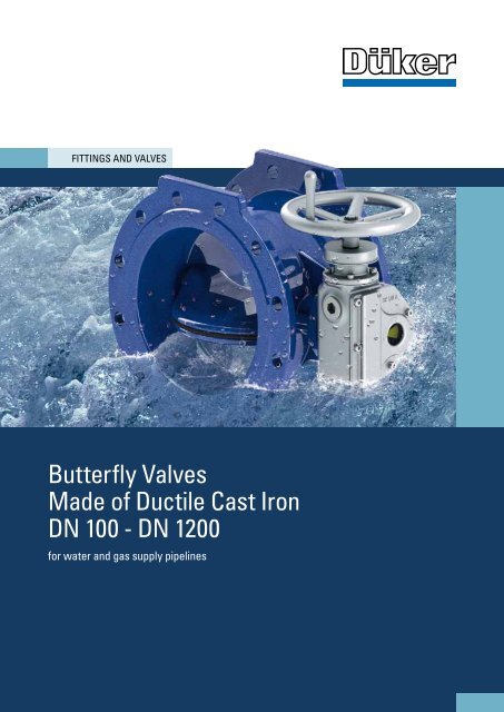
<strong>Butterfly</strong> <strong>Valves</strong><br />
Made of Ductile Cast Iron<br />
DN 100 - DN 1200<br />
for water and gas supply pipelines<br />
1
<strong>Düker</strong> <strong>Butterfly</strong> <strong>Valves</strong> – safe, Flow-optimised and Resistant<br />
In Germany alone, many thousands of kilometres of<br />
pipelines ensure that water is at our disposal every-<br />
where and anytime.<br />
The pipeline materials used for this purpose have to<br />
fulfil high demands:<br />
• resist to any ground movements<br />
• work reliably for years<br />
• remain impeccably hygienic<br />
• transport our drinking water safely and loss-free<br />
It all Depends on the Material<br />
Cast iron as a natural material is the basis of all<br />
<strong>Düker</strong> valves. Due to its excellent material characte-<br />
ristics, it fulfils these requirements completely:<br />
• longevity<br />
• water tightness<br />
• good corrosion resistance<br />
• economy<br />
• and last but not least 100% recyclability<br />
Permanent Protection all around<br />
In order to ensure an even better and permanent protection against corrosion<br />
and incrustation, our butterfly valves are enamelled as a standard coating.<br />
Up to DN 600, the butterfly valves are enamelled inside and outside; above<br />
DN 600 they are enamelled inside.<br />
Bacteria cannot attach themselves to the smooth enamel surface. Therefore, the<br />
adhesion of biofilms is actively avoided, which guarantees absolutely safe drinking<br />
water supply – even in case of varying temperatures.<br />
etec enamel – ths special all around<br />
surface protection for <strong>Düker</strong> butterfly valves<br />
etec enamel – a compound material which forms<br />
an inseparable, chemical bond with the base ma-<br />
terial ductile cast iron, convinces due to:<br />
• corrosion protection inside and outside up to<br />
soil class III<br />
• high resistance against mechanical stress<br />
(friction, impact, pressure, thrust)<br />
• resistance to ageing<br />
• no diffusion of water through the coating,<br />
which might cause blisters between the base<br />
material and the coating<br />
• safety against penetration under the coating<br />
even in case of local damages to the surface<br />
• resistance to climate and medium (UV radiati-<br />
on, humidity, temperature, organic solvants)<br />
<strong>Düker</strong> <strong>Butterfly</strong> <strong>Valves</strong><br />
Our butterfly valves are used both for drinking water and raw water and for all<br />
gas types (including pressurized air). On request, the butterfly valve may also be<br />
used for different media.<br />
Nominal pressures are PN 10, PN 16 and PN 25, with the maximum ope-<br />
rating and differential pressure being equal to the nominal pressure.<br />
The flanges are in accordance with the DIN standards 28604, 28605<br />
or 28606. Flanges as per ASA and BSI are available on request. The<br />
maximum operating temperature for water is 60 °C. The indications for<br />
gas follow G 260 / I.<br />
execution of the Disc<br />
The <strong>Düker</strong> butterfly valves have a flow-optimised, double-eccentric disc. The<br />
profile sealing can easily be adjusted and changed.<br />
The shaft bearings run in maintenance-free bush bearings. The shafts are<br />
sealed through O-rings inside and outside. On the gear box cover, there is an<br />
open/closed indication. The end stop “closed“ of the gear can be adjusted. The<br />
driving can be done with handwheel, an adapter as per GW 366, with an elec-<br />
tric actuator, and with hydraulic or pneumatic actuators.<br />
2 3
<strong>Butterfly</strong> <strong>Valves</strong> type 4510 and 451 – the esse ntial advantages<br />
Flow-Optimised Disc<br />
The <strong>Düker</strong> butterfly valves have a flow-optimised<br />
disc with double-offset journal. This bearing causes<br />
a slight rotation at the moment of opening and clo-<br />
sing the valve, which is in addition superimposed by<br />
a translatory motion. Therefore the disc separates<br />
from the housing at only a slight degree of opening,<br />
which relieves the sealing safely.<br />
Wear-Resistant Bearing and Driving shaft<br />
The bearing sleeves made of bronze are highly wear-resistant and show an<br />
excellent behaviour regarding surface pressure and friction coefficients.<br />
The driving shaft and bearing journal made of stainless steel are chambered<br />
medium-free thanks to a newly developed sealing configuration between the<br />
bearing lug of the disc and the bearing sleeve.<br />
The connection between the disc and the shaft is through a square plug connection.<br />
In combination with the bronze material of the bearing sleeve, this square<br />
plug connection ensures a safe and easy operability.<br />
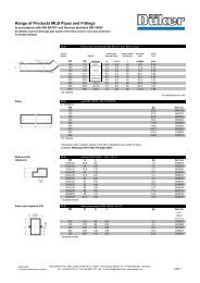
Resistance values (zeta values) in open position<br />
DN type zeta-value<br />
100 4510 0.80<br />
150 4510 0.75<br />
200 4510 0.70<br />
250 4510 0.67<br />
300 4510 0.65<br />
350 4510 0.62<br />
400 4510 0.60<br />
500 4510 0.55<br />
600 4510 0.50<br />
700 451 0.47<br />
800 451 0.45<br />
900 451 0.42<br />
1000 451 0.40<br />
1200 451 0.35<br />
easily Replaceable sealing Ring<br />
This disc sealing, a profile ring, is a resilient-sealing<br />
loop, which runs alongside the shaft axle and seals<br />
directly on the smooth enamel. It is fixed to the disc<br />
with a retaining ring.<br />
The profile ring with one-piece retaining ring ensures<br />
a uniform and controlled pre-tension, which allows<br />
the sealing to be exchanged without problems<br />
in the “open“ position.<br />
Optimised gear Box<br />
As an option, our gear boxes have the following<br />
driving modes:<br />
• handwheel with ball knob<br />
• electric actuator<br />
• stem extension with wheel type indicator<br />
• stem extension without wheel type indicator<br />
The <strong>Düker</strong> gears with slidercrank mechanism have<br />
proven themselves for years and are adapted optimally<br />
to the <strong>Düker</strong> butterfly valve.<br />
At a uniform initial revolution speed, the<br />
closing speed decreases, so the gear closes<br />
softly. This mechanism reduces or eliminates<br />
pressure peaks.<br />
The gear box is chambered watertight and corresponds<br />
to the degree of protection IP 68.<br />
The mechanical position indication (open/closed) is<br />
situated on the gear box below a transparent plastic<br />
cover and is linked directly to the shaft.<br />
4 5
<strong>Butterfly</strong> <strong>Valves</strong> type 4510 and 451 – Materials and Versions<br />
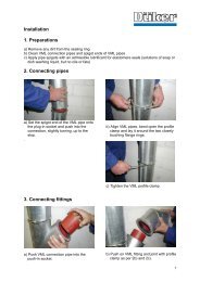
Details and Materials<br />
item description material item description material<br />
1 Body EN-GJS-400-15 18 washer A2<br />
2 Disc EN-GJS-400-15 19 threaded sleeve lower part X20Cr13<br />
3 Retaining ring EN-GJS-500-7 20 threaded sleeve upper part X20Cr13<br />
4 Shaft X20Cr13 21 headless screw A2<br />
5 Bearing journal X20Cr13 22 O-ring NBR<br />
6 Bearing sleeve A GZ-CuSn7SnPb 23 cylinder pin Cq22, Cq35<br />
7 Bearing sleeve B GZ-CuSn7SnPb 24 washer bush POM<br />
8 Sealing ring PE 100 25 countersunk screw A2<br />
9 O-ring NBR 26 O-ring NBR<br />
10 Sealing EPDM 27 countersunk screw A2<br />
11 Profile sealing EPDM 28 countersunk screw A2<br />
12 Blind pin PA6GF30 29 countersunk screw A2<br />
13 <strong>Co</strong>nnection ring module PA6GF30 30 safety ring Ck 75<br />
14 O-ring NBR 31 gearbox SK I/II B EN-GJS-500-7<br />
15 O-ring NBR<br />
16 O-ring NBR<br />
17 Hexagonal screw A2 Other materials on request<br />
6 7<br />
Versions<br />
type DN PN flanged long with<br />
bypass<br />
long without<br />
bypass<br />
Novo<br />
sockets<br />
4510 100 10-25 • •<br />
4510 125 10-25 • •<br />
4510 150 10-25 • • •<br />
4510 200 10-25 • • •<br />
4510 250 10-25 • • •<br />
4510 300 10 • • • • •<br />
4510 300 16 • • • • •<br />
4510 300 25 • • •<br />
4510 350 10-25 • •<br />
4510 400 10 • • • • •<br />
4510 400 16 • • • • •<br />
4510 400 25 • • •<br />
4510 500 10 • • • • •<br />
4510 500 16 • • • • •<br />
4510 500 25 • • •<br />
4510 600 10 • • • •<br />
4510 600 16 • • • •<br />
4510 600 25 • •<br />
etec enamel inside<br />
and outside<br />
451 700 10 • • • •<br />
451 700 16 • • • •<br />
451 700 25 • •<br />
451 800 10-16 • • • •<br />
451 900 10-16 • • • •<br />
451 1000 10-16 • • • •<br />
451 1200 10-16 • •<br />
inside emamel, outside<br />
2-components epoxy paint
<strong>Butterfly</strong> <strong>Valves</strong> with our without Handwheel<br />
Basic version without handwheel with handwheel<br />
model nominal dimension<br />
DN in mm<br />
nominal pressure<br />
PN in bar<br />
length<br />
l in mm<br />
flange<br />
ø D in mm<br />
foot dimension<br />
B in mm<br />
height<br />
h1 in mm<br />
dimension<br />
t1 in mm<br />
dimension<br />
t2 in mm<br />
dimension<br />
x1 in mm<br />
4510 100 10/16 190 220 120 116 110 258 65 I B<br />
4510 100 25 190 235 120 121 110 258 65 I B<br />
4510 125 10/16 200 250 130 131 122 270 65 I B<br />
4510 125 25 200 270 130 141 122 270 65 I B<br />
4510 150 10/16 210 285 150 149 138 286 65 I B<br />
4510 150 25 210 300 150 157 138 286 65 I B<br />
4510 200 10 230 340 160 177 175 311 65 II B<br />
4510 200 16 230 340 160 177 175 311 65 II B<br />
4510 200 25 230 360 160 187 175 311 65 II B<br />
4510 250 10 250 400 180 208 212 348 65 II B<br />
4510 250 16 250 400 180 208 212 348 65 II B<br />
4510 250 25 250 425 180 220 212 348 65 II B<br />
4510 300 10 270 455 200 233 221 371 65 II B<br />
4510 300 16 270 455 200 233 221 371 65 II B<br />
4510 300 25 270 485 200 248 221 371 65 II B<br />
4510 350 10 290 505 225 259 287 426 65 II B<br />
4510 350 16 290 520 225 269 287 426 65 II B<br />
4510 350 25 290 555 225 287 287 426 65 II B<br />
4510 400 10 310 565 300 294 307 446 65 II B<br />
4510 400 16 310 580 300 294 307 474 100 III<br />
4510 400 25 310 620 300 319 307 474 100 III<br />
4510 500 10 350 670 350 350 377 524 100 III<br />
4510 500 16 350 715 350 372 377 524 100 III<br />
4510 600 10 390 780 320 401 442 614 100 III<br />
4510 600 16 390 840 330 431 442 673 160 IV<br />
4510 600 25 390 845 400 431 442 693 160 IV<br />
451 700 10 430 895 400 450 549 665 150 IV<br />
451 700 16 430 910 400 460 549 665 150 IV GZ<br />
451 700 25 430 960 450 485 549 665 150 IV GZ<br />
451 800 10 470 1015 450 510 594 710 150 IV GZ<br />
451 800 16 470 1025 450 515 594 710 150 IV GZ<br />
451 900 10 510 1115 550 560 634 750 150 IV GZ<br />
451 900 16 510 1125 550 568 634 740 200 GS 200 GZ<br />
451 1000 10 550 1230 600 620 699 815 150 IV GZ<br />
451 1000 16 550 1255 600 630 699 805 255 GS 250 GZ<br />
451 1200 10 630 1455 700 730 828 903 255 GS 250 GZ<br />
451 1200 16 630 1485 700 750 828 903 255 GS 250 GZ<br />
gear<br />
sK<br />
height<br />
h2 in mm<br />
stem<br />
ø d in mm<br />
weight<br />
ca. kg<br />
223 20 32<br />
223 20 33<br />
223 20 37<br />
223 20 38<br />
223 20 43<br />
223 20 43<br />
223 20 55<br />
223 20 55<br />
223 20 60<br />
223 20 74<br />
223 20 73<br />
223 20 80<br />
223 20 91<br />
223 20 96<br />
223 20 104<br />
223 20 115<br />
223 20 122<br />
223 20 144<br />
223 20 148<br />
278 20 190<br />
278 20 214<br />
278 20 244<br />
278 20 274<br />
278 20 346<br />
403 30 500<br />
403 30 531<br />
403 30 645<br />
403 / 465 30 / 20 663<br />
403 / 465 30 / 20 748<br />
403 / 465 30 / 20 900<br />
403 / 465 30 / 20 915<br />
403 / 465 30 / 20 1198<br />
465 20 1261<br />
403 / 465 30 / 20 1488<br />
568 20 1655<br />
568 20 2065<br />
568 20 2135<br />
8 9 10<br />
height<br />
h2 in mm<br />
handwheel<br />
ø d1 in mm<br />
weight<br />
ca. kg<br />
325 200 33<br />
325 200 34<br />
325 250 38<br />
325 250 39<br />
325 250 44<br />
325 250 44<br />
325 250 56<br />
325 250 56<br />
325 250 61<br />
325 250 75<br />
325 250 74<br />
325 250 81<br />
325 250 92<br />
325 250 97<br />
325 250 105<br />
325 250 116<br />
325 250 123<br />
325 250 145<br />
325 250 149<br />
315 315 192<br />
315 315 216<br />
315 315 246<br />
315 315 276<br />
315 315 348<br />
500 500 506<br />
500 500 537<br />
570 500 650<br />
745 400 665<br />
745 400 750<br />
745 400 902<br />
745 400 917<br />
745 400 1200<br />
675 400 1263<br />
745 400 1490<br />
715 640 1660<br />
715 640 2070<br />
715 640 2140<br />
disc type 4510<br />
d1<br />
h2<br />
disc type 451<br />
Please note: for the underground installation we supply butterfly valves with height-adjustable telescope stem extension sets in<br />
various lengths. In the nominal dimensions DN 700 up to DN 1200, there is no open/closed indicator included in this case.<br />
DN 800 up to DN 1200: PN 25 is available, however the admissible operating pressure is only 20 bar.
<strong>Butterfly</strong> <strong>Valves</strong> with electric actuator<br />
model nominal dimension<br />
DN in mm<br />
nominal pressure<br />
PN in bar<br />
flange<br />
ø D in mm<br />
foot dimension<br />
B in mm<br />
height<br />
h1 in mm<br />
height<br />
h2 in mm<br />
dimension<br />
t1 in mm<br />
dimension<br />
t2 in mm<br />
dimension<br />
k in mm<br />
4510 100 10/16 220 120 116 445 110 404 557 I B AUMA SA 07.5<br />
4510 100 25 235 120 121 445 110 404 557 I B AUMA SA 07.5<br />
4510 125 10/16 250 130 131 445 122 416 557 I B AUMA SA 07.5<br />
4510 125 25 270 130 141 445 122 416 557 I B AUMA SA 07.5<br />
4510 150 10/16 285 150 149 445 138 432 557 I B AUMA SA 07.5<br />
4510 150 25 300 150 157 445 138 432 557 I B AUMA SA 07.5<br />
4510 200 10 340 160 177 445 175 457 557 II B AUMA SA 07.5<br />
4510 200 16 340 160 177 445 175 457 557 II B AUMA SA 07.5<br />
4510 200 25 360 160 187 445 175 457 557 II B AUMA SA 07.5<br />
4510 250 10 400 180 208 445 212 494 557 II B AUMA SA 07.5<br />
4510 250 16 400 180 208 445 212 494 557 II B AUMA SA 07.5<br />
4510 250 25 425 180 220 445 212 494 557 II B AUMA SA 07.5<br />
4510 300 10 455 200 233 445 221 517 557 II B AUMA SA 07.5<br />
4510 300 16 455 200 233 445 221 517 557 II B AUMA SA 07.5<br />
4510 300 25 485 200 248 445 221 517 557 II B AUMA SA 07.5<br />
4510 350 10 505 225 259 445 287 572 557 II B AUMA SA 07.5<br />
4510 350 16 520 225 269 445 287 572 557 II B AUMA SA 07.5<br />
4510 350 25 555 225 287 445 287 572 557 II B AUMA SA 07.5<br />
4510 400 10 565 300 294 445 307 592 557 II B AUMA SA 07.5<br />
4510 400 16 580 300 294 501 307 574 580 III AUMA SA 10.1<br />
4510 400 25 620 300 319 501 307 574 580 III AUMA SA 10.1<br />
4510 500 10 670 350 350 501 377 624 580 III AUMA SA 10.1<br />
4510 500 16 715 350 372 501 377 624 580 III AUMA SA 10.1<br />
4510 600 10 780 320 401 501 442 714 580 III AUMA SA 10.1<br />
4510 600 16 840 330 431 626 442 773 580 IV AUMA SA 10.1<br />
4510 600 25 845 400 431 626 442 793 580 IV AUMA SA 10.1<br />
451 700 10 895 400 450 590 549 490 490 IVw. red. gear AUMA SA 10.1<br />
451 700 16 910 400 460 830 549 490 490 IV w. red. gear AUMA SA 10.1<br />
451 700 25 960 450 485 830 549 490 490 IV w. red. gear AUMA SA 10.1<br />
451 800 10 1015 450 510 828 594 590 590 IV w. red. gear AUMA SA 10.1<br />
451 800 16 1025 450 515 830 594 600 600 IV w. red. gear AUMA SA 10.1<br />
451 900 10 1115 550 565 830 634 530 530 IV w. red. gear AUMA SA 10.1<br />
451 900 16 1125 550 565 733 699 545 545 GS 200 red. gear AUMA SA 10.1<br />
451 1000 10 1230 600 620 830 699 550 550 IV w. red. gear AUMA SA 10.1<br />
451 1000 16 1255 600 630 817 828 640 640 GS 250 red. gear AUMA SA 10.1<br />
451 1200 10 1455 700 730 817 830 685 685 GS 250 red. gear AUMA SA 10.1<br />
451 1200 16 1485 700 750 817 830 685 685 GS 250 red. gear AUMA SA 10.1<br />
gear<br />
sK<br />
actuator<br />
<strong>Butterfly</strong> Valve with electric actuator aUMa<br />
The standard version of the Auma actuator includes:<br />
• limit switch for the end positions open/closed<br />
• continuously adjustable torque switch for left and right rotation<br />
• indicator flasher for the function indication (1 impulse per rotation)<br />
• three thermo switches<br />
• handwheel for emergency operation<br />
• heating 220V/230V (220V for DN 100/PN10 up to DN 600/PN25; 230V for<br />
DN 700/PN up to DN 1200/PN16)<br />
• central plug for motor and control system, degree of protection of the<br />
actuator IP 67 as per DIN 40050/IEC 529<br />
• three-phase motor 400 V 50 Hz.<br />
Optional extras: mechanical position indication, potentiometer (please indicate<br />
Ohm value), intermediate position switch and tandem switch. On request,<br />
further additional devices are available.<br />
On request, different actuator brands are available.<br />
Please note: DN 800 up to DN 1200: PN 25 is available, however the admissible<br />
operating pressure is only 20 bar.<br />
Please indicate with your inquiry or order:<br />
• motor tension in V<br />
• frequency in Hz<br />
• control tension in Vss<br />
• closing time in minutes<br />
• degree of protection<br />
11 12 13<br />
disc type 4510<br />
disc type 451
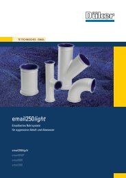
<strong>Butterfly</strong> <strong>Valves</strong> long Body, with Bypass<br />
Use of <strong>Butterfly</strong> <strong>Valves</strong> with Bypass<br />
The butterfly valves with bypass serve for the otherwise difficult air release<br />
from pipelines with several high points.<br />
The bypass normally contains its own shut-off valve and is dimensioned to<br />
one tenth of the main nominal dimension. The length of the standard butterfly<br />
valve is increased in order to install the bypass, to the length as per EN 558<br />
series 15 (F15).<br />
the bypass has two main advantages:<br />
• the supply pipelines can be filled slowly for efficient air release<br />
• the valves, which are under pressure from one side, can be operated without<br />
requiring elevated force. The required pressure equalisation is carried out<br />
via the bypass. Therefore the pipeline is protected from pressure peaks.<br />
model nominal dimension<br />
DN in mm<br />
nominal pressure<br />
PN in bar<br />
length<br />
l in mm<br />
flange<br />
ø D in mm<br />
Operation of the <strong>Butterfly</strong> Valve with Bypass<br />
Normally, when opening the valve, first the bypass<br />
valve and then the main valve are opened. While<br />
the water flows, both valves remain open.<br />
The process is applied vice versa when closing the<br />
valves: First the main valve, then the bypass valve<br />
is closed.<br />
Air vent problems and pressure peaks do not pose<br />
a problem in this procedure.<br />
Basic long version with bypass*<br />
foot dimension<br />
B in mm<br />
height<br />
h1 in mm<br />
height<br />
h2 in mm<br />
dimension<br />
t4 in mm<br />
4510 300 10 500 455 200 233 223 317 II B<br />
4510 300 16 500 455 200 233 223 317 II B<br />
4510 400 10 600 565 300 294 223 392 II B<br />
4510 400 16 600 580 300 294 223 420 III<br />
4510 500 10 700 670 350 350 278 470 III / GS 125 GZ<br />
4510 500 16 700 715 350 372 278 470 III<br />
4510 600 10 800 780 320 401 278 560 III / GS 160 GZ<br />
4510 600 16 800 840 330 431 278 619 IV<br />
451 700 10 900 895 400 450 403 665 IV<br />
451 700 16 900 910 400 460 403 665 IV<br />
451 800 10 1000 1015 450 510 403 710 IV GZ<br />
451 800 16 1000 1025 450 515 403 710 IV GZ<br />
451 1000 10 1200 1230 600 620 403 805 IV GZ<br />
451 1000 16 1200 1255 600 630 568 805 IV GZ<br />
* long version without bypass on request<br />
14 15<br />
gear<br />
sK<br />
dimension<br />
t1 in mm<br />
dimension<br />
t2 in mm<br />
DN of the<br />
bypass in mm<br />
weight<br />
in kg<br />
480 405 40 150<br />
480 405 40 150<br />
559 485 40 218<br />
559 485 40 259<br />
568 505 50 333<br />
568 505 50 366<br />
637 554 50 462<br />
637 554 50 635<br />
745 650 80 680<br />
745 650 80 680<br />
840 730 80 1085<br />
840 730 80 1085<br />
965 845 100 2060<br />
965 845 100 2060<br />
disc type 4510<br />
disc type 451
<strong>Butterfly</strong> <strong>Valves</strong> with Novo sockets<br />
type nominal dimension<br />
DN in mm<br />
nominal pressure<br />
PN in bar<br />
socket<br />
ø D in mm<br />
length<br />
ete in mm<br />
length<br />
l in mm<br />
foot dimension<br />
B in mm<br />
height<br />
h1 in mm<br />
height<br />
h2 in mm<br />
dimension<br />
t1 in mm<br />
dimension<br />
t2 in mm<br />
4510 150 10 - 25 216 106 360 150 147 300 177 231 I B<br />
4510 200 10 - 25 271 111 383 160 175 300 202 256 II B<br />
4510 250 10 - 25 324 116 398 180 205 300 248 300 II B<br />
4510 300 10 - 25 381 121 413 200 230 380 263 317 II B<br />
4510 400 10 - 25 489 172 472 250 285 380 328 382 III<br />
4510 500 10 - 25 598 205 527 300 340 400 370 465 III<br />
Thrust-resisting connections of ductile iron butterfly<br />
valves with pipes made of PEHD plastic are<br />
possible in the nominal dimensions DN 150 up to<br />
DN 200.<br />
16 17<br />
gear<br />
sK<br />
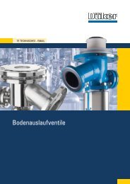
Quality on the Highest level<br />
<strong>Düker</strong> valves are used worldwide and are subject to elevated requirements in<br />
the drinking water sector. Therefore each valve is tested with extreme care<br />
before it leaves the factory.<br />
It goes without saying that the requirements of the DVGW worksheet W 270<br />
“Reproduction of microorganisms on materials for the drinking water sector –<br />
tests and evaluation“ are observed.<br />
Quality Management<br />
We apply high requirements on the quality of our products. Therefore, as early<br />
as in 1993, we introduced a modern quality management system as per EN ISO<br />
9001, which is certified by TÜV CERT. Furthermore our products are tested and<br />
approved according to numerous other product or market-specific standards<br />
and regulations.<br />
For some products, in the framework of quality protection associations, we voluntarily<br />
observe criteria that surpass the standard requirements by far.<br />
Regular and random tests, internal and external audits, but also our staff‘s<br />
motivation ensure that the QM system, as an integral part of the overall organisation,<br />
is permanently developed. This means, also for the future, that we<br />
supply products which convince through their longevity and are up to the latest<br />
state of the art.
18<br />
FIttINgs aND ValVes<br />
DRaINage teCHNOlOgY<br />
eNgINeeRINg<br />
glass lININg teCHNOlOgIes<br />
JOBBINg FOUNDRY<br />
778250 / 04.12 specifications subjetct to change without notice<br />
<strong>Düker</strong> gmbH & <strong>Co</strong>. Kgaa<br />
Hauptstraße 39-41<br />
63846 laufach<br />
germany<br />
tel. +49 6093 87-0<br />
Fax +49 6093 87-246<br />
Internet: www.dueker.de<br />
e-Mail: info@dueker.de