Pulse Generator RUP6-12c - GBS Elektronik GmbH
Pulse Generator RUP6-12c - GBS Elektronik GmbH
Pulse Generator RUP6-12c - GBS Elektronik GmbH

You also want an ePaper? Increase the reach of your titles
YUMPU automatically turns print PDFs into web optimized ePapers that Google loves.
<strong>Pulse</strong> <strong>Generator</strong> <strong>RUP6</strong>-<strong>12c</strong><br />
• True square wave pulse with active<br />
switching off<br />
• Arbitrary pulse width<br />
• rise time ~200 ns<br />
• frequency up to 3 kHz<br />
• voltage up to 12 kV<br />
• peak current up to 120 A<br />
• short circuit proof<br />
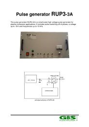
The <strong>RUP6</strong> is a new universal solid state pulse<br />
generator which may be constructed for voltages up to<br />
30 kV.<br />
Prominent features are high pulse current, very high<br />
efficiency, scaleability of the voltage and an ultra fast<br />
switching off in case of arcs.<br />
The <strong>RUP6</strong> consists of numbers of 1 kV pulse modules<br />
which are charged in parallel and are switched in<br />
series during pulse. Power supply and modulator are<br />
integrated within this principle.<br />
Technical Data<br />
Current and Voltage<br />
• output impedance about 10 Ohm, corresponding<br />
to 0.8 Ohm per module.<br />
• internal pulse capacity about 4.2µF, corresponding<br />
to 50 µF per module.<br />
• peak current 120 A. Overcurrent for more than 2<br />
µs will activate short circuit switch off. The inherent<br />
short circuit current limit is about 200 A. An Arc<br />
(sudden short circuit within a pulse) will initiate<br />
switch off within 500 ns<br />
• average current 500 mA max.<br />
• maximum output pulse voltage 12 kV. Output<br />
pulse voltage can be adjusted continously,<br />
however, there is a hysteresis of about 1% in the<br />
voltage regulation, so accuracy as well as<br />
minimum voltage is in the order of 120V.<br />
• maximum output power 6 kW, decreasing with<br />
duty cycle. Pout=Pmax *(1 - frequency * (pulse<br />
width + 150µs))<br />
Wave Form and Frequency<br />
• square wave with variable pulse width and variable<br />
frequency<br />
• rise time about 200 ns<br />
• fall time 3 µs maximum, eventually faster<br />
depending on load.<br />
• pulse width 0.5 µs - 100 µs, using external control<br />
or computer control also longer. Principally the<br />
internal pulse capacitor should not discharge more<br />
than 10 % of the maximum rated voltage.<br />
• Duty cycle can be chosen nearly arbitrarily, it has<br />
only to be noted that maximum possible output<br />
power will linearly decrease to zero when the duty<br />
cycle is approaching 100%, as the internal power<br />
supply is off during pulse and starts again after<br />
end of pulse with a 150µs delay..<br />
• maximum frequency 3 kHz<br />
• control of voltage, pulse width and frequency by<br />
potentiometers on the front or alternatively by<br />
computer control via RS 232 interface. <strong>Pulse</strong><br />
control may also be done by external TTL signal at<br />
the control input at the front and voltage control is<br />
possible by an analog voltage (0-10V).<br />
Mechanical, included items<br />
• rack, 780 * 553 * 1630 mm (depth, width, height)<br />
• grid supply 3 * 480 V<br />
• 2m output cable<br />
• Internal controller, addressable by RS232, with the<br />
following functionalities:<br />
• programmable pulse generator<br />
• control of output voltage<br />
• wave form control (peak current, peak voltage)<br />
• Arc counter<br />
• RS232 light fibre cable<br />
• software for PC<br />
• documentation<br />
Safety<br />
• external interlock<br />
• a fast short circuit detection protects the pulse<br />
modules from damage by short circuit or arcing in<br />
the load.<br />
• short circuit currents are inherently limited to<br />
200 A.<br />
• The pulse generator in compatible to regulations<br />
about electromagnetic compatibility (EMC).<br />
Not included or to be provided<br />
oscilloscope<br />
Warranty<br />
Warranty includes email and telephone support, spare<br />
sparts, labour and shipping costs to customer. It does<br />
not cover travelling costs nor eventual shipping costs<br />
from customer.<br />
Servicing should be done by experienced personell<br />
only as there are hazardous voltages inside the device.<br />
Company address<br />
<strong>GBS</strong> <strong>Elektronik</strong> <strong>GmbH</strong><br />
Bautzener Landstr. 22<br />
01454 Großerkmannsdorf<br />
Tel.: ++49 351 217007-0<br />
Fax: ++49 351 217007-21<br />
Email: kontakt@gbs-elektronik.de<br />
http://www.gbs-elektronik.de<br />
All given data and parameters are by best knowledge. Changes<br />
may be reserved.<br />
Stand 6.05
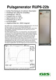
principial scheme of pulse generator
<strong>RUP6</strong>-12 layout<br />
Control elements front plate<br />
1: main switch<br />
2: control lamps phase<br />
3: high voltage off<br />
4: high voltage on<br />
5: switch voltage control computer / front plate<br />
6: Reset internal controller<br />
7: RS232 interface to computer<br />
8: control signal input 3-10V (TTL recommended)<br />
9: voltage monitor output 1:1000<br />
10: current monitor output 100 mV/A<br />
11: LED Arc<br />
12: Internal pulse generation on/off<br />
13: HV voltage<br />
control<br />
14: pulse width<br />
control<br />
15: frequency<br />
control<br />
16: display<br />
module voltage<br />
17: display<br />
average current<br />
18: LED remote<br />
control<br />
Connectors back<br />
side<br />
19: central<br />
ground<br />
connection<br />
20: interlock<br />
connection<br />
21: output pulse voltage (RG11 cable)<br />
22: grid supply cable<br />
23: feedthrough for cable from MDXII supply