HAL® 1820, HAL 28xy, HAL 3625 - Glyn
HAL® 1820, HAL 28xy, HAL 3625 - Glyn
HAL® 1820, HAL 28xy, HAL 3625 - Glyn

Create successful ePaper yourself
Turn your PDF publications into a flip-book with our unique Google optimized e-Paper software.
Approval Document<br />
Application APN000055_001EN<br />
Note<br />
Software IC Kits/Boards<br />
Edition ??? April 16, 2010<br />
ANK000???_00?EN<br />
ANS000???_00?EN<br />
ANI000???_00?EN<br />
APN000055_001EN<br />
April 16, 2010<br />
<strong>HAL</strong> ®<br />
<strong>1820</strong>, <strong>HAL</strong> <strong>28xy</strong>,<br />
<strong>HAL</strong> <strong>3625</strong><br />
Application Board <strong>HAL</strong>-APB V1.3
<strong>HAL</strong> <strong>1820</strong>, <strong>HAL</strong> <strong>28xy</strong>, <strong>HAL</strong> <strong>3625</strong> APPLICATION NOTE<br />
Application Board <strong>HAL</strong>-APB V1.3<br />
Copyright, Warranty,<br />
and Limitation of<br />
Liability<br />
Micronas Trademarks – <strong>HAL</strong><br />
The information and data contained in this document are believed to be accurate and<br />
reliable. The software and proprietary information contained therein may be protected<br />
by copyright, patent, trademark and/or other intellectual property rights of Micronas. All<br />
rights not expressly granted remain reserved by Micronas.<br />
Micronas assumes no liability for errors and gives no warranty representation or guarantee<br />
regarding the suitability of its products for any particular purpose due to these<br />
specifications.<br />
By this publication, Micronas does not assume responsibility for patent infringements or<br />
other rights of third parties which may result from its use. Commercial conditions, product<br />
availability and delivery are exclusively subject to the respective order confirmation.<br />
Any information and data which may be provided in the document can and do vary in<br />
different applications, and actual performance may vary over time.<br />
All operating parameters must be validated for each customer application by customers’<br />
technical experts. Any new issue of this document invalidates previous issues.<br />
Micronas reserves the right to review this document and to make changes to the document’s<br />
content at any time without obligation to notify any person or entity of such revision<br />
or changes. For further advice please contact us directly.<br />
Do not use our products in life-supporting systems, aviation and aerospace applications!<br />
Unless explicitly agreed to otherwise in writing between the parties, Micronas’<br />
products are not designed, intended or authorized for use as components in systems<br />
intended for surgical implants into the body, or other applications intended to support or<br />
sustain life, or for any other application in which the failure of the product could create a<br />
situation where personal injury or death could occur.<br />
No part of this publication may be reproduced, photocopied, stored on a retrieval system<br />
or transmitted without the express written consent of Micronas.<br />
Third-Party Trademarks All other brand and product names or company names may be trademarks of their<br />
respective companies.<br />
2 April 16, 2010; APN000055_001EN Micronas
APPLICATION NOTE <strong>HAL</strong> <strong>1820</strong>, <strong>HAL</strong> <strong>28xy</strong>, <strong>HAL</strong> <strong>3625</strong><br />
Contents<br />
Page Section Title<br />
5 1. Introduction<br />
5 1.1. General Information<br />
5 1.2. Introduction<br />
6 1.2.1. Supported <strong>HAL</strong> Sensors<br />
6 1.2.2. Sensor-specific PC Software<br />
6 1.3. Board Block Diagram<br />
8 2. Getting started<br />
8 2.1. First Steps<br />
8 2.1.1. Check <strong>HAL</strong>-APB V1.3<br />
8 2.1.2. Check Communication with PC and Hall Sensor Connection<br />
9 3. Board Configuration<br />
9 3.1. Jumper Settings<br />
11 3.2. <strong>HAL</strong> Interface Connector<br />
12 4. Specification<br />
12 4.1. Recommended Operating Conditions<br />
12 4.2. Characteristics<br />
13 5. USB Driver Installation<br />
13 5.1. Deinstalling USB D2xx Drivers<br />
14 5.2. Installing the USB VCP Drivers<br />
17 6. Board Functions<br />
17 6.1. Serial Command Interpreter<br />
17 6.1.1. Serial Interface Configuration<br />
17 6.1.2. Definition of the COMMAND Frame<br />
18 6.1.3. Definition of the RESPONSE Frame<br />
18 6.1.4. Analog Measurements<br />
19 6.1.5. Error Codes<br />
20 7. Board Mode Settings<br />
20 7.1. Board Operation Modes<br />
20 7.2. Board Configuration Commands<br />
22 8. Programming Interface<br />
22 8.1. Bit Definition<br />
23 8.2. Telegram Parameters<br />
24 8.3. Command Structures of Protocol<br />
25 8.4. Locking of the Sensor<br />
26 9. <strong>HAL</strong> <strong>1820</strong><br />
26 9.1. <strong>HAL</strong> <strong>1820</strong> - Board commands<br />
27 9.2. <strong>HAL</strong> <strong>1820</strong> - Programming Examples<br />
29 10. <strong>HAL</strong> 2810 – Board Commands<br />
29 10.1. LIN Interface<br />
29 10.1.1. LIN Interface Mode Configuration<br />
29 10.1.2. Schedule Tables<br />
30 10.1.3. Error Handling<br />
31 10.2. <strong>HAL</strong> 2810 (LIN2.0) – Board commands<br />
33 10.3. <strong>HAL</strong> 2810 (LIN2.0) – Programming Examples<br />
Application Board <strong>HAL</strong>-APB V1.3<br />
Micronas April 16, 2010; APN000055_001EN 3
<strong>HAL</strong> <strong>1820</strong>, <strong>HAL</strong> <strong>28xy</strong>, <strong>HAL</strong> <strong>3625</strong> APPLICATION NOTE<br />
Application Board <strong>HAL</strong>-APB V1.3<br />
Contents, continued<br />
Page Section Title<br />
37 11. <strong>HAL</strong> 2830 / <strong>HAL</strong> 2850 – Board Commands<br />
37 11.1. Biphase-M Interface<br />
37 11.2. <strong>HAL</strong> 2830 / <strong>HAL</strong> 2850 – Board commands<br />
39 11.3. <strong>HAL</strong> 2830 / <strong>HAL</strong> 2850 – Programming Examples<br />
43 12. <strong>HAL</strong> <strong>3625</strong> – Board Commands<br />
43 12.1. <strong>HAL</strong> <strong>3625</strong> – Board commands<br />
45 12.2. <strong>HAL</strong> <strong>3625</strong> – Programming Examples<br />
47 13. Application Note History<br />
4 April 16, 2010; APN000055_001EN Micronas
APPLICATION NOTE <strong>HAL</strong> <strong>1820</strong>, <strong>HAL</strong> <strong>28xy</strong>, <strong>HAL</strong> <strong>3625</strong><br />
1. Introduction<br />
1.1. General Information<br />
Application Board <strong>HAL</strong>-APB V1.3<br />
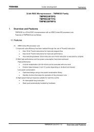
The hardware and software description in this document is valid for the Application<br />
Board <strong>HAL</strong>-APB V1.3.<br />
Fig. 1–1: Application Board <strong>HAL</strong>-APB V1.3<br />
1.2. Introduction<br />
The Application Board <strong>HAL</strong>-APB V1.3 (<strong>HAL</strong>-APB) is an board for programming the<br />
Micronas Hall-effect sensor families with analog and digital output formats. The board<br />
is equipped with a Micronas Flash microcontroller CDC 3207G. It provides an application<br />
software supporting a command interface for the communication with a PC. This<br />
allows the implementation of specific PC software for engineering purposes or in-line<br />
calibration. The <strong>HAL</strong>-APB can be ordered with a housing or as a PCB version.<br />
In the case of a housing, an additional extension board with two sockets for the connection<br />
of up to two Hall sensors (depending on the sensor type) is supplied.<br />
Micronas April 16, 2010; APN000055_001EN 5
<strong>HAL</strong> <strong>1820</strong>, <strong>HAL</strong> <strong>28xy</strong>, <strong>HAL</strong> <strong>3625</strong> APPLICATION NOTE<br />
Application Board <strong>HAL</strong>-APB V1.3<br />
1.2.1. Supported <strong>HAL</strong> Sensors<br />
The <strong>HAL</strong>-APB supports the sensors listed in Table 1–1.<br />
Table 1–1: Supported sensors<br />
Sensor Remark<br />
<strong>HAL</strong> <strong>1820</strong> 3-wire device<br />
<strong>HAL</strong> 2810 LIN 2.0 Interface<br />
<strong>HAL</strong> 2830 SENT Interface<br />
<strong>HAL</strong> 2850 Fast PWM, 3-wire device<br />
<strong>HAL</strong> <strong>3625</strong> Direct angle sensor<br />
Please refer to the corresponding Programming Environment Application Notes for<br />
detailed information on the sensors listed or contact the Application Support Sensors<br />
(support_sensor@micronas.com).<br />
1.2.2. Sensor-specific PC Software<br />
Micronas GmbH provides easy-to-use PC software (LabView) for each supported sensor.<br />
This Application Note describes how to use it with the different sensors.<br />
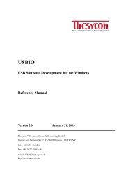
1.3. Board Block Diagram<br />
V_Board<br />
GND<br />
USB<br />
EEPROM<br />
RS232<br />
5V-MCU<br />
5V-PER<br />
MCU<br />
CDC3207<br />
JTAG<br />
Fig. 1–2: <strong>HAL</strong>-APB block diagram<br />
OLED<br />
Extension<br />
(optional)<br />
LIN<br />
5V-ANA Module<br />
(optional)<br />
Hall<br />
Interface<br />
6 April 16, 2010; APN000055_001EN Micronas
APPLICATION NOTE <strong>HAL</strong> <strong>1820</strong>, <strong>HAL</strong> <strong>28xy</strong>, <strong>HAL</strong> <strong>3625</strong><br />
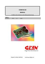
V_Board<br />
GND<br />
Voltage<br />
Reference<br />
Slew<br />
Control<br />
(Optional)<br />
MCU<br />
VDD_Hall Driver<br />
Voltage Level<br />
Control<br />
A/D<br />
Sens<br />
VOUT1<br />
Fig. 1–3: Detailed view of <strong>HAL</strong> Interface<br />
Application Board <strong>HAL</strong>-APB V1.3<br />
Micronas April 16, 2010; APN000055_001EN 7<br />
Digital<br />
Transceiver<br />
Switch<br />
Switch<br />
TP8 - IDD<br />
TP VDD<br />
A/D<br />
Sens<br />
VDD/3<br />
Hall device<br />
VDD<br />
VOUT_1<br />
VOUT_2<br />
GND
<strong>HAL</strong> <strong>1820</strong>, <strong>HAL</strong> <strong>28xy</strong>, <strong>HAL</strong> <strong>3625</strong> APPLICATION NOTE<br />
Application Board <strong>HAL</strong>-APB V1.3<br />
2. Getting started<br />
2.1. First Steps<br />
2.1.1. Check <strong>HAL</strong>-APB V1.3<br />
– Connect the <strong>HAL</strong>-APB to the supply voltage.<br />
– Check if the power-on self-test was passed successfully. (ERROR LED is switched<br />
off after power on. Exception: LIN mode)<br />
Board Supply<br />
The <strong>HAL</strong>-APB requires a stabilized power supply. For this purpose, either when using it<br />
without housing, the connector X2 (DC jack) or the terminal beneath it can be used.<br />
Power-On Self-Test<br />
The <strong>HAL</strong>-APB firmware provides a power-on self-test. The self-test is started after connecting<br />
the board supply. During the self-test, the status LEDs including the Error LED,<br />
will flash.<br />
In case of a detected error, the ERROR LED remains illuminated after the self-test. In<br />
LIN mode the ERROR LED is switched on as long as the Vsupply of the sensor is not<br />
set to 12 V.<br />
2.1.2. Check Communication with PC and Hall Sensor Connection<br />
Connect a Hall sensor with the <strong>HAL</strong>-APB.<br />
(a) directly into the socket <strong>HAL</strong> 1<br />
or<br />
(b) into the socket X1 of the <strong>HAL</strong>-APB extension board (housing version).<br />
Note: For the first communication check, we recommend using the <strong>HAL</strong> <strong>28xy</strong> Programming<br />
Environment LabView software provided by Micronas for the specific<br />
<strong>HAL</strong> sensor.<br />
you can also<br />
– set up a Hyperterminal connection (see Section 6 on page 17)<br />
– switch Vdd on using the “vho1” command (see Section 7.2 on page 20).<br />
– try to read out a register (see chapter of the used sensor type).<br />
8 April 16, 2010; APN000055_001EN Micronas
APPLICATION NOTE <strong>HAL</strong> <strong>1820</strong>, <strong>HAL</strong> <strong>28xy</strong>, <strong>HAL</strong> <strong>3625</strong><br />
3. Board Configuration<br />
3.1. Jumper Settings<br />
Application Board <strong>HAL</strong>-APB V1.3<br />
For changing between LIN-Bus and Biphase-M communication, jumpers need to be set<br />
differently. For non-housed (optional) application boards it may be necessary to switch<br />
jumper for USB/RS-232 connection. The following pictures show how to set the jumpers<br />
correctly.<br />
X4 - RS232<br />
(SUB-D-9)<br />
SW<br />
JP3<br />
X3<br />
USB<br />
(B)<br />
<strong>HAL</strong>-APB<br />
Version 1.3<br />
JP4<br />
JP7<br />
JP5<br />
JP6<br />
CDC3207G<br />
<strong>HAL</strong>1<br />
Status LEDs on housing<br />
JP1<br />
Reset<br />
TP8<br />
+18 VDC<br />
Fig. 3–4: Jumper settings <strong>HAL</strong>-APB V1.3<br />
The default jumper position Pos1 is indicated by black bars in Fig. 3–4.<br />
Micronas April 16, 2010; APN000055_001EN 9<br />
X2<br />
Status LEDs<br />
TP7<br />
RJ-45<br />
<strong>HAL</strong>1/2<br />
+ −
<strong>HAL</strong> <strong>1820</strong>, <strong>HAL</strong> <strong>28xy</strong>, <strong>HAL</strong> <strong>3625</strong> APPLICATION NOTE<br />
Application Board <strong>HAL</strong>-APB V1.3<br />
Table 3–2: Jumper settings<br />
Jumper Setting Function<br />
JP1 pos1 (default)<br />
pos2<br />
JP2 pos1 (default)<br />
pos2<br />
JP3 close (default)<br />
open<br />
JP4 close (default)<br />
open<br />
JP5 close (default)<br />
open<br />
JP6 close (default)<br />
open<br />
JP7 open (default)<br />
close<br />
debug<br />
normal operation<br />
normal operation<br />
reserved<br />
USB<br />
RS-232<br />
Note: JP7 must not be set in combination with JP4 and JP5<br />
Table 3–3: Board LED description<br />
LED Name Function<br />
ERROR On, in case of communication error<br />
READY On, after power-on of board<br />
VDD_Hall equals GND when<br />
Vsup is switched off<br />
VDD_Hall is floating when<br />
Vsup is switched off<br />
normal operation<br />
only for LIN Bus applications<br />
normal operation<br />
only for LIN Bus applications<br />
normal operation<br />
only for LIN bus applications<br />
PCCOM On, in case of communication between PC and <strong>HAL</strong>-<br />
APB<br />
<strong>HAL</strong>_RD Telegram on VOUT<br />
<strong>HAL</strong>_PR reserved<br />
<strong>HAL</strong>_WR Telegram high level on Hall VDD<br />
<strong>HAL</strong>_ON Hall VDD on<br />
10 April 16, 2010; APN000055_001EN Micronas
APPLICATION NOTE <strong>HAL</strong> <strong>1820</strong>, <strong>HAL</strong> <strong>28xy</strong>, <strong>HAL</strong> <strong>3625</strong><br />
3.2. <strong>HAL</strong> Interface Connector<br />
Application Board <strong>HAL</strong>-APB V1.3<br />
Depending on the sensor type, up to two sensors can be connected to the board. For<br />
this purpose, a 6-pin connector <strong>HAL</strong>1/2 is provided. Alternatively, one Hall Sensor can<br />
be inserted in the 3-pin socket <strong>HAL</strong> beneath the connector <strong>HAL</strong>1/2 (only available for<br />
boards without housing).<br />
The pins of this socket are connected parallel to pins VDD=1/4, GND=2/5,<br />
Sensor1_OUT=3, Sensor2_OUT=6 of the connector <strong>HAL</strong>1/2. The male plug (modular<br />
RJ-12, OST (MMJ) coding) corresponding to the fawn connector <strong>HAL</strong>1/2 can be<br />
ordered from every electronics store. The pinning of the interface is described in<br />
Table 3–4.<br />
Table 3–4: Pinning of the <strong>HAL</strong> interface<br />
Pin No. Description<br />
1 Sensor input<br />
VDD Sensor 1<br />
2 Common Sensor GND<br />
3 Sensor output V OUT/DIO Sensor 1<br />
4 Sensor input<br />
VDD Sensor 2<br />
5 Common Sensor GND<br />
6 Sensor output V OUT/DIO Sensor 2<br />
Fig. 3–5: Modular connector <strong>HAL</strong>1/2, front view<br />
Micronas April 16, 2010; APN000055_001EN 11
<strong>HAL</strong> <strong>1820</strong>, <strong>HAL</strong> <strong>28xy</strong>, <strong>HAL</strong> <strong>3625</strong> APPLICATION NOTE<br />
Application Board <strong>HAL</strong>-APB V1.3<br />
Table 4–5: Board conditions<br />
4. Specification<br />
4.1. Recommended Operating Conditions<br />
All voltages are referenced to GND (-VB pin at X1 = GND at X2)<br />
Symbol Parameter Connector Limit Values Unit Test Conditions<br />
4.2. Characteristics<br />
Min. Typ. Max.<br />
ISUP Supply Current X2 - 180 - mA<br />
V SUP Supply Voltage X2 16 18 20 V<br />
C L Load Capacitance <strong>HAL</strong>1/2 - - 100 nF<br />
Table 4–6: Board characteristics<br />
All voltages are referenced to GND (-VB pin at X1 = GND at X2)<br />
Symbol Parameter Connector Limit Values Unit Test Conditions<br />
Min. Typ. Max.<br />
I SUP_<strong>HAL</strong> Output Load Current <strong>HAL</strong>1/2 - - 40 mA Supply current per<br />
device<br />
V OUT_<strong>HAL</strong><br />
I DD_<strong>HAL</strong>_th<br />
Output Voltage of Hall<br />
Device<br />
Current Level Threshold<br />
(Biphase in Two-Wire)<br />
V DD_<strong>HAL</strong>_NORM NORM Level of <strong>HAL</strong> Supply<br />
Voltage<br />
V DD_<strong>HAL</strong>_LOW<br />
V DD_<strong>HAL</strong>_HIGH<br />
LOW Level of <strong>HAL</strong> Supply<br />
Voltage<br />
HIGH Level of <strong>HAL</strong> Supply<br />
Voltage<br />
<strong>HAL</strong>1/2 0<br />
0<br />
- 5<br />
Note: The voltage levels and the current threshold on the two-wire interface are<br />
trimmed by the manufacturer. If any of the levels listed are found to be outside<br />
the specification limits, please contact the manufacturer or the Application Support<br />
Sensors Team.<br />
12 April 16, 2010; APN000055_001EN Micronas<br />
18<br />
V<br />
V<br />
Standard configuration<br />
(default)<br />
LIN configuration<br />
only!<br />
<strong>HAL</strong> 1/2 11.3 11.8 tbd mA One device with twowire<br />
interface connected<br />
with <strong>HAL</strong>1<br />
<strong>HAL</strong> 1/2 4.9 5 5.1 V<br />
<strong>HAL</strong> 1/2 5.4 5.5 5.6 V<br />
<strong>HAL</strong> 1/2 7.9 8.0 8.1 V
APPLICATION NOTE <strong>HAL</strong> <strong>1820</strong>, <strong>HAL</strong> <strong>28xy</strong>, <strong>HAL</strong> <strong>3625</strong><br />
5. USB Driver Installation<br />
Application Board <strong>HAL</strong>-APB V1.3<br />
Note: When using the serial cable you do not need to install this drivers. They are only<br />
necessary for connecting the Application Board <strong>HAL</strong>-APB V1.3 via USB cable to<br />
the PC.<br />
5.1. Deinstalling USB D2xx Drivers<br />
For using the FTDI VCP drivers you first need to remove the FTDI D2xx drivers. Therefore<br />
start the Control Panel on your PC and double-click the “Add or Remove Programs“<br />
Icon.<br />
Fig. 5–6: Control Panel<br />
Scroll to the entry FTDI FTD2xx USB Drivers and press the Change/Remove Button.<br />
Unplug the Application Board <strong>HAL</strong>-APB V1.3 and click Continue. The D2xx Drivers will<br />
be removed automatically.<br />
Micronas April 16, 2010; APN000055_001EN 13
<strong>HAL</strong> <strong>1820</strong>, <strong>HAL</strong> <strong>28xy</strong>, <strong>HAL</strong> <strong>3625</strong> APPLICATION NOTE<br />
Application Board <strong>HAL</strong>-APB V1.3<br />
Fig. 5–7: FTDI uninstaller dialog<br />
5.2. Installing the USB VCP Drivers<br />
Plug in the Application Board <strong>HAL</strong>-APB V1.3 (Power supply also connected). The<br />
Found new Hardware Wizard starts.<br />
Fig. 5–8: Hardware wizard<br />
Select Install from a specific location (Advanced).<br />
14 April 16, 2010; APN000055_001EN Micronas
APPLICATION NOTE <strong>HAL</strong> <strong>1820</strong>, <strong>HAL</strong> <strong>28xy</strong>, <strong>HAL</strong> <strong>3625</strong><br />
Fig. 5–9: Driver location dialog<br />
Select Don’t search I will choose the driver to install.<br />
Fig. 5–10: Selection of hardware type<br />
Application Board <strong>HAL</strong>-APB V1.3<br />
Select some kind of device (e.g. Disk drives) to get the next window.<br />
Micronas April 16, 2010; APN000055_001EN 15
<strong>HAL</strong> <strong>1820</strong>, <strong>HAL</strong> <strong>28xy</strong>, <strong>HAL</strong> <strong>3625</strong> APPLICATION NOTE<br />
Application Board <strong>HAL</strong>-APB V1.3<br />
Fig. 5–11: Have Disk... dialog<br />
Please, press the Have Disk... button.<br />
Fig. 5–12: Browsing to driver location<br />
Browse to the location, where the VCP drivers are stored (e.g. CD:\USB-Drivers\...)<br />
and click Open.<br />
Proceed with Ok and next until the wizard finishes.<br />
Note: Sometimes the installer repeats the whole procedure. If this happens please do<br />
the same as explained above again.<br />
16 April 16, 2010; APN000055_001EN Micronas
APPLICATION NOTE <strong>HAL</strong> <strong>1820</strong>, <strong>HAL</strong> <strong>28xy</strong>, <strong>HAL</strong> <strong>3625</strong><br />
6. Board Functions<br />
6.1. Serial Command Interpreter<br />
Application Board <strong>HAL</strong>-APB V1.3<br />
This board provides a serial command interpreter for the interaction with a PC, connected<br />
via USB or RS232.<br />
The serial communication protocol applies a software handshake:<br />
– The PC acts as a master, the <strong>HAL</strong>-APB V1.3 as slave,<br />
– The <strong>HAL</strong>-APB V1.3 responds to each master COMMAND frame with a RESPONSE<br />
frame.<br />
6.1.1. Serial Interface Configuration<br />
When using a hyperterminal communication please set the following parameters.<br />
Table 6–7: parameter settings of serial interface<br />
Parameter Value<br />
Bits per second 9600<br />
Data bits 8<br />
Parity Even<br />
Stop bits 1<br />
Flow control none<br />
6.1.2. Definition of the COMMAND Frame<br />
The command frame is of variable length. There are basically two types of commands:<br />
1. for board configuration<br />
2. for communication with connected Hall device<br />
The command string has to end with (ASCII character 0x0D), optionally with<br />
(ASCII characters 0x0D, 0x0A).<br />
Micronas April 16, 2010; APN000055_001EN 17
<strong>HAL</strong> <strong>1820</strong>, <strong>HAL</strong> <strong>28xy</strong>, <strong>HAL</strong> <strong>3625</strong> APPLICATION NOTE<br />
Application Board <strong>HAL</strong>-APB V1.3<br />
Table 6–8: Available commands<br />
Command Code Explanation<br />
READ<br />
<strong>HAL</strong> <strong>28xy</strong><br />
<strong>HAL</strong> <strong>1820</strong>, <strong>HAL</strong> <strong>3625</strong><br />
WRITE<br />
<strong>HAL</strong> <strong>28xy</strong><br />
<strong>HAL</strong> <strong>1820</strong>, <strong>HAL</strong> <strong>3625</strong><br />
6.1.3. Definition of the RESPONSE Frame<br />
The response frame consists of 7...10 characters plus 1 finishing <br />
:.... <br />
ST is non-zero in case of errors (see Table 6–9)<br />
The Rx-characters contain the received data depending on the command (see devicedependent<br />
command lists in section 9, 10, ...).<br />
6.1.4. Analog Measurements<br />
Its also possible to measure analog voltages, as the <strong>HAL</strong>_VDD or the <strong>HAL</strong>_VOUT with<br />
the ADC of the <strong>HAL</strong>-APB. The <strong>HAL</strong>_OUT is only correctly measurable when <strong>HAL</strong>_VDD<br />
equals 5 V.<br />
Example<br />
ftvdl0 (set VDD to 5 V)<br />
ftana1 (measure <strong>HAL</strong>_VDD)<br />
ftana2 (measure <strong>HAL</strong>_VOUT)<br />
V DD = DATA / 1024 x 3 x 5V<br />
V OUT = DATA / 1024 x 5V<br />
DATA is measured by ftana command as explained in Table 7–11.<br />
18 April 16, 2010; APN000055_001EN Micronas<br />
2<br />
1<br />
3<br />
6<br />
read a register<br />
write a register
APPLICATION NOTE <strong>HAL</strong> <strong>1820</strong>, <strong>HAL</strong> <strong>28xy</strong>, <strong>HAL</strong> <strong>3625</strong><br />
6.1.5. Error Codes<br />
Table 6–9: Error codes<br />
STATUS Error<br />
0 no error<br />
1 Biphase-M: ACK error<br />
2 Biphase-M: data read error<br />
3 Biphase-M: CAPCOM<br />
4 Biphase-M TPROG select error<br />
5 ADC error:<br />
supply voltage level out of spec<br />
6 clock off error<br />
7 Biphase-M: PROG ACK error<br />
8 reserved<br />
9 reserved<br />
10 (0xA) division by zero error<br />
11 (0xB) reserved<br />
12 (0xC) CRC check error<br />
13 (0xD) data format error<br />
14 (0xE) unspecified system error<br />
15 (0xF) invalid command<br />
Application Board <strong>HAL</strong>-APB V1.3<br />
Micronas April 16, 2010; APN000055_001EN 19
<strong>HAL</strong> <strong>1820</strong>, <strong>HAL</strong> <strong>28xy</strong>, <strong>HAL</strong> <strong>3625</strong> APPLICATION NOTE<br />
Application Board <strong>HAL</strong>-APB V1.3<br />
Table 7–11: Board configuration<br />
7. Board Mode Settings<br />
7.1. Board Operation Modes<br />
In order to meet the different requirements of the various Hall devices, the board can<br />
be run in different operation modes. When a particular device is used, the corresponding<br />
board mode has to be selected first. The mode list can be displayed by sending the<br />
board command “?m”.<br />
Table 7–10: Board modes<br />
Mode Description<br />
8 <strong>HAL</strong> 2810 – LIN Mode<br />
9 <strong>HAL</strong> 2830/50 – Biphase Mode<br />
A <strong>HAL</strong> <strong>1820</strong> – 3-wire Mode<br />
<strong>HAL</strong> <strong>3625</strong> – 3-wire Mode<br />
C <strong>HAL</strong> <strong>3625</strong> – Biphase DIO<br />
7.2. Board Configuration Commands<br />
The board configuration commands shall be used to<br />
– select the board mode<br />
– set/read configuration data like the bit time or firmware version<br />
– control the power supply VDD_<strong>HAL</strong> of the connected sensor<br />
Action Command Parameter Remarks<br />
get firmware version ?v return :[Version] firmware release version<br />
Example<br />
=> ?v<br />
smA<br />
vho1<br />
APPLICATION NOTE <strong>HAL</strong> <strong>1820</strong>, <strong>HAL</strong> <strong>28xy</strong>, <strong>HAL</strong> <strong>3625</strong><br />
Table 7–11: Board configuration<br />
Action Command Parameter Remarks<br />
Application Board <strong>HAL</strong>-APB V1.3<br />
Switch VDD_<strong>HAL</strong> off vho0 returnvalue: :00000 switch off <strong>HAL</strong> Supply voltage<br />
(default 5 V; see voltage levels for details)<br />
Example<br />
=> vho0<br />
ftana1<br />
ftana2<br />
<strong>HAL</strong> <strong>1820</strong>, <strong>HAL</strong> <strong>28xy</strong>, <strong>HAL</strong> <strong>3625</strong> APPLICATION NOTE<br />
Application Board <strong>HAL</strong>-APB V1.3<br />
8. Programming Interface<br />
8.1. Bit Definition<br />
Note: The following description is only valid fo Biphase-M communication but not for<br />
LIN mode!<br />
In Biphase-M Programming Mode the sensor is addressed by modulating a serial<br />
telegram on the sensors supply or output voltage. The sensor answers with a modulation<br />
of the output voltage.<br />
A logical “0“ is coded as no level change within the bit time. A logical “1“ is coded as a<br />
level change of typically 50% of the bit time. After each bit, a level change occurs (see<br />
Fig. 8–13).<br />
The serial telegram is used to transmit the EEPROM content, error codes and digital<br />
values of the magnetic field from and to the sensor.<br />
Fig. 8–13: Definition of logical 0 and 1 bit<br />
22 April 16, 2010; APN000055_001EN Micronas
APPLICATION NOTE <strong>HAL</strong> <strong>1820</strong>, <strong>HAL</strong> <strong>28xy</strong>, <strong>HAL</strong> <strong>3625</strong><br />
8.2. Telegram Parameters<br />
Table 8–12: Telegram parameters (all voltages are referenced to GND)<br />
Application Board <strong>HAL</strong>-APB V1.3<br />
Symbol Parameter Pin No. Limit Values Unit<br />
V DDL<br />
V DDH<br />
V DDProgram<br />
t p0<br />
Supply Voltage for Low Level<br />
during Programming through<br />
Sensor V DD Pin<br />
Supply Voltage for High Level<br />
during Programming through<br />
Sensor V DD Pin<br />
VDD Voltage for EEPROM programming<br />
(after PROG and<br />
ERASE)<br />
Bit time if command send to the<br />
sensor<br />
Min. Typ. Max.<br />
1 5.8 6.3 6.6 V<br />
1 6.8 7.3 7.8 V<br />
1 5 5.5 6.5 V<br />
1 - 1024 - µs<br />
t pOUT Bit time for sensor answer 3 - 1024 - µs<br />
t PROG Programming time for EEPROM - - 2 - ms<br />
Micronas April 16, 2010; APN000055_001EN 23
<strong>HAL</strong> <strong>1820</strong>, <strong>HAL</strong> <strong>28xy</strong>, <strong>HAL</strong> <strong>3625</strong> APPLICATION NOTE<br />
Application Board <strong>HAL</strong>-APB V1.3<br />
command structure<br />
8.3. Command Structures of Protocol<br />
COM: command bit<br />
ADR: address bit<br />
check: command and address check bit<br />
dummy: dummy bit (always 0)<br />
Two-Wire Mode<br />
WRITE, ERASE,<br />
PROG<br />
commands<br />
sensor input<br />
(VDD mod.)<br />
sensor output<br />
(IDD mod.)<br />
READV, READN<br />
commands<br />
sensor input<br />
(VDD mod.)<br />
sensor output<br />
(IDD mod.)<br />
Three-Wire Mode / Bidirectional on VOUT<br />
WRITE, ERASE,<br />
PROG<br />
commands<br />
sensor I/O<br />
(VOUT) READV, READN<br />
commands<br />
sensor I/O<br />
(VOUT) SYNC<br />
COM2<br />
COM1<br />
COM0<br />
ADR4<br />
SYNC<br />
COM2<br />
COM1<br />
COM0<br />
ADR4<br />
DAT15<br />
DAT15<br />
SYNC: start bit (always 0)<br />
DAT: data bit<br />
CRC: CRC bit<br />
ADR3<br />
ADR2<br />
ADR1<br />
ADR0<br />
parity<br />
dummy 0<br />
ADR3<br />
ADR2<br />
ADR1<br />
ADR0<br />
parity<br />
DAT13<br />
DAT13<br />
dummy 0<br />
ACK: acknowledge<br />
DAT15<br />
DAT14<br />
DAT13<br />
DAT12<br />
DAT11<br />
DAT10<br />
DAT9<br />
DAT8<br />
DAT7<br />
DAT6<br />
DAT5<br />
DAT4<br />
DAT3<br />
DAT2<br />
DAT1<br />
: master’s output<br />
to sensor’s OUTpin<br />
is hiZ<br />
DAT0<br />
CRC3<br />
CRC2<br />
24 April 16, 2010; APN000055_001EN Micronas<br />
ACK<br />
CRC1<br />
CRC0<br />
SYNC<br />
dummy 0<br />
COM2<br />
COM1<br />
DAT14<br />
COM0<br />
ADR4<br />
DAT12<br />
ADR3<br />
DAT11<br />
ADR2<br />
DAT10<br />
ADR1<br />
DAT9<br />
SYNC<br />
ADR0<br />
DAT8<br />
COM2<br />
parity<br />
DAT7<br />
COM1<br />
DAT6<br />
COM0<br />
DAT15<br />
DAT5<br />
ADR4<br />
DAT14<br />
DAT4<br />
ADR3<br />
DAT13<br />
DAT3<br />
ADR2<br />
DAT12<br />
DAT2<br />
ADR1<br />
DAT11<br />
DAT1<br />
ADR0<br />
DAT10<br />
DAT0<br />
parity<br />
DAT9<br />
CRC3<br />
DAT8<br />
CRC2<br />
DAT7<br />
CRC1<br />
dummy 0<br />
DAT6<br />
CRC0<br />
DAT5<br />
DAT14<br />
DAT4<br />
DAT3<br />
DAT12<br />
DAT2<br />
DAT1<br />
DAT11<br />
DAT10<br />
DAT0<br />
DAT9<br />
CRC3<br />
DAT8<br />
CRC2<br />
DAT7<br />
CRC1<br />
DAT6<br />
CRC0<br />
DAT5<br />
DAT4<br />
DAT3<br />
DAT2<br />
ACK<br />
DAT1<br />
DAT0<br />
CRC3<br />
CRC2<br />
CRC1<br />
CRC0
APPLICATION NOTE <strong>HAL</strong> <strong>1820</strong>, <strong>HAL</strong> <strong>28xy</strong>, <strong>HAL</strong> <strong>3625</strong><br />
command structure -2-<br />
COM: command bit<br />
ADR: address bit<br />
check: command and address check bit<br />
dummy: dummy bit (always 0)<br />
sensor input<br />
(VDD mod.)<br />
sensor output<br />
(VDD mod.)<br />
SYNC<br />
COM2<br />
COM1<br />
COM0<br />
ADR4<br />
SYNC<br />
COM2<br />
COM1<br />
COM0<br />
dummy 0<br />
Application Board <strong>HAL</strong>-APB V1.3<br />
Note: In case of <strong>HAL</strong><strong>1820</strong> communication the last edge of CRC0 will finish on analog<br />
voltage level!<br />
8.4. Locking of the Sensor<br />
SYNC: start bit (always 0)<br />
DAT: data bit<br />
CRC: CRC bit<br />
Three-Wire Mode (Biphase-In = VDD / Biphase-Out = VOUT)<br />
WRITE, ERASE,<br />
PROG<br />
commands<br />
READV, READN<br />
commands<br />
sensor input<br />
(VDD mod.)<br />
sensor output<br />
(VDD mod.)<br />
ADR4<br />
ADR3<br />
ADR2<br />
ADR1<br />
ADR0<br />
parity<br />
ADR3<br />
ADR2<br />
ADR1<br />
DAT15<br />
DAT14<br />
ADR0<br />
DAT13<br />
dummy 0<br />
parity<br />
ACK: acknowledge<br />
DAT15<br />
DAT14<br />
DAT13<br />
DAT12<br />
DAT11<br />
DAT10<br />
DAT9<br />
DAT8<br />
DAT7<br />
DAT6<br />
DAT5<br />
DAT4<br />
DAT3<br />
DAT2<br />
DAT1<br />
DAT12<br />
DAT11<br />
DAT10<br />
DAT9<br />
DAT8<br />
DAT7<br />
DAT6<br />
DAT5<br />
DAT4<br />
DAT3<br />
DAT2<br />
DAT1<br />
DAT0<br />
CRC3<br />
CRC2<br />
CRC1<br />
CRC0<br />
: master’s output<br />
to sensor’s OUTpin<br />
is hiZ<br />
DAT0<br />
CRC3<br />
CRC2<br />
For production and qualification tests, it is mandatory to set the LOCK bit after final<br />
adjustment and programming. The LOCK function is active after the next power-up of<br />
the sensor.<br />
The success of the LOCK process should be checked by reading the status of the<br />
LOCK bit after locking and/or by an analog check of the sensors output signal.<br />
Electro-static discharges (ESD) may disturb the programming pulses. Please take precautions<br />
against ESD. For the programming during product development and also for<br />
production purposes, a programming tool including hardware and software is available<br />
on request. It is recommended to use the Micronas tool kit for an easy product development.<br />
Micronas April 16, 2010; APN000055_001EN 25<br />
ACK<br />
CRC1<br />
CRC0
<strong>HAL</strong> <strong>1820</strong>, <strong>HAL</strong> <strong>28xy</strong>, <strong>HAL</strong> <strong>3625</strong> APPLICATION NOTE<br />
Application Board <strong>HAL</strong>-APB V1.3<br />
9. <strong>HAL</strong> <strong>1820</strong><br />
The <strong>HAL</strong> <strong>1820</strong> is a universal magnetic field sensor with a linear output, based on the<br />
Hall effect. It features two different customer modes. In Application Mode the sensor<br />
provides a ratiometric analog output voltage. In Programming Mode it is possible to<br />
change the register settings of the sensor. After a power-up the sensor is always operating<br />
in the Programming Mode (default after delivery from Micronas and as long as the<br />
sensor is not locked). It is switched to Application Mode by setting a certain volatile bit<br />
in the memory of the sensor or by locking the sensor.<br />
9.1. <strong>HAL</strong> <strong>1820</strong> - Board commands<br />
Table 9–13: <strong>HAL</strong> <strong>1820</strong> - Board commands<br />
Note: For general board commands see Table 7–11 on page 20<br />
Action Command Parameter Remarks<br />
write data to address xxwSTR STR = ADR1 ADR0 DAT3 DAT2<br />
DAT1 DAT0 CRC<br />
address as 2-digit hex No.<br />
data as 4-digit hex No.<br />
CRC checksum as 1-digit hex No.<br />
Example<br />
=> xxw1022223<br />
address as 2-digit hex No.<br />
Example<br />
=> xxr10<br />
xxres<br />
APPLICATION NOTE <strong>HAL</strong> <strong>1820</strong>, <strong>HAL</strong> <strong>28xy</strong>, <strong>HAL</strong> <strong>3625</strong><br />
9.2. <strong>HAL</strong> <strong>1820</strong> - Programming Examples<br />
BEGIN<br />
Tx:“smA”<br />
Rx:“0:00000”<br />
Tx:“vho1”<br />
Rx:“0:00001”<br />
Application Board <strong>HAL</strong>-APB V1.3<br />
Fig. 9–14: Flowchart: initialize <strong>HAL</strong>-APB V1.3 in <strong>HAL</strong> <strong>1820</strong> 3-wire mode<br />
Fig. 9–15: Flowchart: write data 0x0000 to <strong>HAL</strong> <strong>1820</strong> register 0x08<br />
Set Mode <strong>HAL</strong><strong>1820</strong> - 3wire<br />
switch V DD_<strong>HAL</strong> ON<br />
Note: For calculating CRC value refer to the Application Note “<strong>HAL</strong> <strong>1820</strong> programming”<br />
or contact the Application Support Sensors Team.<br />
Micronas April 16, 2010; APN000055_001EN 27<br />
END<br />
BEGIN<br />
Tx:“xxw0800004”<br />
Rx:“0:000000”<br />
END<br />
write to address 0x08<br />
data = 0x0000, crc =4
<strong>HAL</strong> <strong>1820</strong>, <strong>HAL</strong> <strong>28xy</strong>, <strong>HAL</strong> <strong>3625</strong> APPLICATION NOTE<br />
Application Board <strong>HAL</strong>-APB V1.3<br />
BEGIN<br />
Tx:“xxr10”<br />
Rx:“0:XXXXX”<br />
Fig. 9–16: Flowchart: read data from <strong>HAL</strong> <strong>1820</strong> register 0x10<br />
read register 0x10<br />
28 April 16, 2010; APN000055_001EN Micronas<br />
END
APPLICATION NOTE <strong>HAL</strong> <strong>1820</strong>, <strong>HAL</strong> <strong>28xy</strong>, <strong>HAL</strong> <strong>3625</strong><br />
10. <strong>HAL</strong> 2810 – Board Commands<br />
Application Board <strong>HAL</strong>-APB V1.3<br />
The <strong>HAL</strong> <strong>28xy</strong> family consists of members with different digital interfaces like LIN,<br />
PWM and SENT. All members within this family can be programmed without any additional<br />
programming pin. Programming is done via LIN frames or Biphase-M telegrams<br />
depending on the family member.<br />
10.1. LIN Interface<br />
Note: For the LIN2.0 Mode, the hardware configuration of the <strong>HAL</strong>-APB V1.3 must be<br />
changed. For details (see Section 3 on page 9).<br />
The LIN Interface on the <strong>HAL</strong>-APB V1.3 is intended to be used with one <strong>HAL</strong> 2810 sensor<br />
as a point to point communication. The firmware comprises a master driver for LIN<br />
protocol 2.0. A slave mode is not implemented.<br />
10.1.1. LIN Interface Mode Configuration<br />
Note: In case of LIN configuration the bus voltage level is equal to V Board (normally<br />
18 V).<br />
For using this mode correct the V DD_<strong>HAL</strong> has to be set to 12V too. This is done by sending<br />
the two commands<br />
=> ftvdp1(setting programming voltage = 12V)<br />
=> vho1(switching on V DD_<strong>HAL</strong> )<br />
10.1.2. Schedule Tables<br />
Different schedule tables allow the use of unconditional frames and diagnostic/configuration<br />
frames. It is possible to switch between 4 schedule tables, where tables 1 to 3<br />
handle unconditional frames and table 4 handles configuration frames. The PIDs given<br />
in the table are the default settings in the <strong>HAL</strong>-APB V1.3 firmware schedule table settings.<br />
The PIDs of the unconditional frames in the schedule tables 1 to 3 can be<br />
changed in the test terminal.<br />
This can be only done while the corresponding table is not scheduled! The number of<br />
response bytes is set to a fixed value for each frame insida a schedule table. If a PID is<br />
changed accordingly, this length is applied to the new PID. Changed PIDs are lost after<br />
powering off the <strong>HAL</strong>-APB V1.3. Each schedule table includes only two LIN frames!<br />
The scheduling time between frames is set to 20 ms (fixed).<br />
Note: To apply more user friendly behaviour, especially for the saving of special PID<br />
settings, the calling application software should implement the preservation of<br />
the PID settings.<br />
Micronas April 16, 2010; APN000055_001EN 29
<strong>HAL</strong> <strong>1820</strong>, <strong>HAL</strong> <strong>28xy</strong>, <strong>HAL</strong> <strong>3625</strong> APPLICATION NOTE<br />
Application Board <strong>HAL</strong>-APB V1.3<br />
Table 10–14:Schedule Tables unconditional frames of the <strong>HAL</strong>-APB V1.3<br />
Table Number Description<br />
ID_Table_1 Default scheduling table after startup. It comprises a “set address“ to<br />
prepare a data access (W/nR=0) and a “Read 2 bytes“ frame. The<br />
address is arbitrary. the default scheduling prevents the sensor from<br />
going into sleep.<br />
Frame1: PID = 0x03 (set address), 3 bytes<br />
Frame2: PID = 0xc4 (Read 2 bytes), 2 bytes<br />
ID_Table_2 This ttable prepares an address to read from (W/nR=0) and performs a<br />
4 byte read from there.<br />
Frame1: PID = 0x03 (set address), 3 bytes<br />
Frame 2: PID = 0x85, (Read 4 bytes), 4 bytes<br />
ID_Table_3 This table comprises a frame to write a byte to an address (W/nR=1). A<br />
second frame includes only a dummy 4 byte read from this address.<br />
Frame1: PID = 0x03 (set address), 3 bytes<br />
Frame2: PID = 0x85 (Read 4 bytes), 4 bytes<br />
Table 10–15:Schedule table configuration frames of the <strong>HAL</strong>-APB V1.3<br />
Table Number Description<br />
ID_Table_4 This table contains configuration frames to schedule.<br />
The two frames are a request (PID60) and a response (PID61 ) frame.<br />
the data bytes to be used with the request frame can be set by the user.<br />
Frame1: PID60 = 0x3C, 8bytes<br />
Frame2: PID61 =0x7D, 8bytes<br />
10.1.3. Error Handling<br />
A global error flag is set if a LIN communication error, e.g. a shorted bus or a disconnected<br />
slave has been detected. There is no certain fault confinement implemented but<br />
only this global error information. The last error information can be kept alive or reset.<br />
30 April 16, 2010; APN000055_001EN Micronas
APPLICATION NOTE <strong>HAL</strong> <strong>1820</strong>, <strong>HAL</strong> <strong>28xy</strong>, <strong>HAL</strong> <strong>3625</strong><br />
Table 10–16:<strong>HAL</strong> 2810 commands<br />
10.2. <strong>HAL</strong> 2810 (LIN2.0) – Board commands<br />
Note: For general board commands see Table 7–11 on page 20<br />
Application Board <strong>HAL</strong>-APB V1.3<br />
function command parameter remarks<br />
switch schedule table lsstabN N = 1...4<br />
return value: :00000000<br />
set address<br />
= Prepare Data Access<br />
set address<br />
= Write Byte<br />
send single shot of<br />
schedule table 3<br />
lwpaSTR STR = <br />
return value:<br />
:<br />
lwaSTR STR = <br />
return value:<br />
:<br />
lsos - Example<br />
N schedule table No.<br />
board status<br />
Example<br />
=> lsstab1<br />
lwpa3081<br />
=> :00000000<br />
address as 4-digit hex<br />
No.<br />
board status<br />
data as 8-digit hex No.<br />
Example<br />
=> lwa308100<br />
=> :00000000<br />
=> lsos<br />
<strong>HAL</strong> <strong>1820</strong>, <strong>HAL</strong> <strong>28xy</strong>, <strong>HAL</strong> <strong>3625</strong> APPLICATION NOTE<br />
Application Board <strong>HAL</strong>-APB V1.3<br />
Table 10–16:<strong>HAL</strong> 2810 commands<br />
function command parameter remarks<br />
get configuration data<br />
(byte 4...7)<br />
assign PID to schedule<br />
table<br />
lrch return value:<br />
: board status<br />
data as 8-digit hex No.<br />
lspidSTR STR = <br />
return value: :... board status<br />
data as 8-digit hex No.<br />
read error state lrer return value:<br />
: board status<br />
data as 8-digit hex No.<br />
reset error state lrercN N = 0 / 1<br />
return value: :00000000<br />
tbd.<br />
board status<br />
32 April 16, 2010; APN000055_001EN Micronas
APPLICATION NOTE <strong>HAL</strong> <strong>1820</strong>, <strong>HAL</strong> <strong>28xy</strong>, <strong>HAL</strong> <strong>3625</strong><br />
Application Board <strong>HAL</strong>-APB V1.3<br />
10.3. <strong>HAL</strong> 2810 (LIN2.0) – Programming Examples<br />
BEGIN<br />
Tx:“sm8”<br />
Rx:“0:00008”<br />
Tx:“ftvdp1”<br />
Rx:“0:00001”<br />
Tx:“vho1”<br />
Rx:“0:00001”<br />
Fig. 10–17:Initialize Board for <strong>HAL</strong> 2810 (LIN2.0) Mode<br />
Set Mode <strong>HAL</strong>2810 - 3wire<br />
(ERROR LED is red due<br />
to low VDD_<strong>HAL</strong> )<br />
switch VDD_<strong>HAL</strong> ON<br />
(ERROR LED is off)<br />
Micronas April 16, 2010; APN000055_001EN 33<br />
END<br />
set VDD_<strong>HAL</strong> to 12V<br />
(ERROR LED is red due<br />
to low VDD_<strong>HAL</strong> )
<strong>HAL</strong> <strong>1820</strong>, <strong>HAL</strong> <strong>28xy</strong>, <strong>HAL</strong> <strong>3625</strong> APPLICATION NOTE<br />
Application Board <strong>HAL</strong>-APB V1.3<br />
BEGIN<br />
Tx:“lsstab0001”<br />
Rx:“0:00000000” Rx:“D:00000000”<br />
if not yet selected if already selected<br />
Tx:“lwpa0002”<br />
Rx:“0:00000000”<br />
Delay 40 ms<br />
Tx:“lrd”<br />
Rx:“0:00000FFA”<br />
END<br />
Fig. 10–18:<strong>HAL</strong> 2810 (LIN2.0) – read 2 bytes<br />
Switch to schedule table #1<br />
Define Address 0x0002<br />
Allow the scheduler to<br />
send the schedule table<br />
Get the data<br />
34 April 16, 2010; APN000055_001EN Micronas
APPLICATION NOTE <strong>HAL</strong> <strong>1820</strong>, <strong>HAL</strong> <strong>28xy</strong>, <strong>HAL</strong> <strong>3625</strong><br />
BEGIN<br />
Tx:“lsstab0002”<br />
Rx:“0:00000000” Rx:“D:00000000”<br />
if not yet selected if already selected<br />
Tx:“lwpa0002”<br />
Rx:“0:00000000”<br />
Delay 80 ms<br />
Tx:“lrd”<br />
Rx:“0:F04FFFA”<br />
END<br />
Fig. 10–19:<strong>HAL</strong> 2810 (LIN2.0) – read 4 bytes<br />
Application Board <strong>HAL</strong>-APB V1.3<br />
Switch to schedule table #2<br />
Define Address 0x0002<br />
Allow the scheduler to<br />
send the schedule table<br />
Get the data<br />
Micronas April 16, 2010; APN000055_001EN 35
<strong>HAL</strong> <strong>1820</strong>, <strong>HAL</strong> <strong>28xy</strong>, <strong>HAL</strong> <strong>3625</strong> APPLICATION NOTE<br />
Application Board <strong>HAL</strong>-APB V1.3<br />
BEGIN<br />
Tx:“lwa000600”<br />
Rx:“0:00000000”<br />
Tx:“lsos”<br />
Rx:“0:00000000”<br />
Delay 200 ms<br />
Tx:“lrd”<br />
Rx:“0:00008000”<br />
END<br />
Fig. 10–20:<strong>HAL</strong> 2810 (LIN2.0) – write byte<br />
Write Byte 0x00 to Address 0x0006<br />
Execute a single shot of<br />
schedule table #3<br />
Allow the scheduler to<br />
send the schedule table<br />
Get the data<br />
36 April 16, 2010; APN000055_001EN Micronas
APPLICATION NOTE <strong>HAL</strong> <strong>1820</strong>, <strong>HAL</strong> <strong>28xy</strong>, <strong>HAL</strong> <strong>3625</strong><br />
Application Board <strong>HAL</strong>-APB V1.3<br />
11. <strong>HAL</strong> 2830 / <strong>HAL</strong> 2850 – Board Commands<br />
The <strong>HAL</strong> <strong>28xy</strong> family consists of members with different digital interfaces like LIN,<br />
PWM and SENT. All members within this family can be programmed without any additional<br />
programming pin. Programming of <strong>HAL</strong> 2830 and <strong>HAL</strong> 2850 is done via<br />
Biphase-M telegrams.<br />
11.1. Biphase-M Interface<br />
Note: For the PWM/SENT Mode, the hardware configuration of the <strong>HAL</strong>-APB V1.3<br />
needs to be changed to Biphase-M. For details (see Section 3.1 on page 9).<br />
11.2. <strong>HAL</strong> 2830 / <strong>HAL</strong> 2850 – Board commands<br />
Table 11–17:<strong>HAL</strong> 2830 / <strong>HAL</strong> 2850 commands<br />
Note: For general board commands see Table 7.2 on page 20<br />
function command parameter remarks<br />
read PWM-Period and<br />
Pulsewidth<br />
(only <strong>HAL</strong> 2850)<br />
prN N = 0 / 1<br />
return value:<br />
:<br />
N trigger on falling/rising PWM edge<br />
board status<br />
4digit Period<br />
4digit Pulsewidth<br />
Example<br />
=> pr1 (OP-bit=0)<br />
:0FFB2<br />
Micronas April 16, 2010; APN000055_001EN 37
<strong>HAL</strong> <strong>1820</strong>, <strong>HAL</strong> <strong>28xy</strong>, <strong>HAL</strong> <strong>3625</strong> APPLICATION NOTE<br />
Application Board <strong>HAL</strong>-APB V1.3<br />
Table 11–17:<strong>HAL</strong> 2830 / <strong>HAL</strong> 2850 commands<br />
function command parameter remarks<br />
set base address pxsbSTR STR = <br />
read byte with base<br />
address<br />
returns data from<br />
address to address+1<br />
write byte with base<br />
address<br />
write word with base<br />
address<br />
return value: :000000<br />
pxrbSTR STR = <br />
return value: :<br />
pxwbSTR STR = <br />
return value: :000000<br />
pxwwSTR STR = <br />
return value: :00000000<br />
baseaddress as 4-digit hex No.<br />
checksum<br />
board status<br />
Example<br />
=> pxsb30006<br />
=> :000000<br />
address as 2-digit hex No.<br />
board status<br />
Data as 4-digit hex No.<br />
checksum<br />
Example<br />
=> pxrb00<br />
pxwb00000<br />
APPLICATION NOTE <strong>HAL</strong> <strong>1820</strong>, <strong>HAL</strong> <strong>28xy</strong>, <strong>HAL</strong> <strong>3625</strong><br />
Application Board <strong>HAL</strong>-APB V1.3<br />
11.3. <strong>HAL</strong> 2830 / <strong>HAL</strong> 2850 – Programming Examples<br />
BEGIN<br />
Tx:“sm9”<br />
Rx:“0:00009”<br />
Tx:“vho1”<br />
Rx:“0:00001”<br />
Fig. 11–21:Initialize Board for <strong>HAL</strong> 2830 / <strong>HAL</strong> 2850 (SENT / fastPWM) Mode<br />
Fig. 11–22:measure PWM duty cycle (only <strong>HAL</strong> 2850!)<br />
Fig. 11–23:<strong>HAL</strong> 2830 / <strong>HAL</strong> 2850 customer mode switch<br />
Set Mode <strong>HAL</strong>2830/<strong>HAL</strong>2850<br />
Biphase-M - 3wire<br />
switch V DD_<strong>HAL</strong> ON<br />
Micronas April 16, 2010; APN000055_001EN 39<br />
END<br />
BEGIN<br />
Tx:“pr1”<br />
Rx:“0:13AE0A00”<br />
END<br />
measure Duty Cycle<br />
pr1 (OP-bit=0)<br />
<strong>HAL</strong> <strong>1820</strong>, <strong>HAL</strong> <strong>28xy</strong>, <strong>HAL</strong> <strong>3625</strong> APPLICATION NOTE<br />
Application Board <strong>HAL</strong>-APB V1.3<br />
BEGIN<br />
Tx:“pcms”<br />
Rx:“0:000000”<br />
switch <strong>HAL</strong>2830 / <strong>HAL</strong>2850<br />
from Application Mode into<br />
Programming Mode<br />
Fig. 11–24:<strong>HAL</strong> 2830 / <strong>HAL</strong> 2850 read from an address with base address 0<br />
40 April 16, 2010; APN000055_001EN Micronas<br />
END<br />
BEGIN<br />
Tx:“pxsb30006”<br />
Rx:“0:000000”<br />
Tx:“pxrb00”<br />
Rx:“0:D4537”<br />
END<br />
set base address to 0x3000<br />
(calculated crc = 6)<br />
read from address 0x00<br />
with base address 0x3000<br />
(data=D453, crc=7)
APPLICATION NOTE <strong>HAL</strong> <strong>1820</strong>, <strong>HAL</strong> <strong>28xy</strong>, <strong>HAL</strong> <strong>3625</strong><br />
BEGIN<br />
Tx:“pxsb30006”<br />
Rx:“0:000000”<br />
Tx:“pxrb00”<br />
Rx:“0:D4537”<br />
Application Board <strong>HAL</strong>-APB V1.3<br />
set base address to 0x3000<br />
(calculated crc = 6)<br />
Fig. 11–25:<strong>HAL</strong> 2830 / <strong>HAL</strong> 2850 read from any address with specified base address<br />
Fig. 11–26:<strong>HAL</strong> 2830 / <strong>HAL</strong> 2850 write byte to any address with specified base<br />
address<br />
Micronas April 16, 2010; APN000055_001EN 41<br />
END<br />
BEGIN<br />
Tx:“pxsb30006”<br />
Rx:“0:000000”<br />
Tx:“pxwb00000”<br />
Rx:“0:000000”<br />
END<br />
read from address 0x00<br />
with base address 0x3000<br />
(data=D453, crc=7)<br />
set base address to 0x3000<br />
(calculated crc = 6)<br />
write 0x00 to address 0x00<br />
with base address 0x3000<br />
(crc=0)
<strong>HAL</strong> <strong>1820</strong>, <strong>HAL</strong> <strong>28xy</strong>, <strong>HAL</strong> <strong>3625</strong> APPLICATION NOTE<br />
Application Board <strong>HAL</strong>-APB V1.3<br />
BEGIN<br />
Tx:“pxsb30006”<br />
Rx:“0:000000”<br />
Tx:“pxww0000000”<br />
Rx:“0:000000”<br />
set base address to 0x3000<br />
(calculated crc = 6)<br />
Fig. 11–27:<strong>HAL</strong> 2830 / <strong>HAL</strong> 2850 write word to any address with specified base<br />
address<br />
42 April 16, 2010; APN000055_001EN Micronas<br />
END<br />
write 0x0000 to address 0x00<br />
with base address 0x3000<br />
(crc=0)
APPLICATION NOTE <strong>HAL</strong> <strong>1820</strong>, <strong>HAL</strong> <strong>28xy</strong>, <strong>HAL</strong> <strong>3625</strong><br />
Table 12–18:<strong>HAL</strong> <strong>3625</strong> commands<br />
12. <strong>HAL</strong> <strong>3625</strong> – Board Commands<br />
Application Board <strong>HAL</strong>-APB V1.3<br />
The <strong>HAL</strong> <strong>3625</strong> is a member of a new generation of Hall-effect sensors with vertical hall<br />
plate technology. With the new vertical Hall technology it is possible to directly measure<br />
rotation angles in a range of 0° to 360° with simple magnetic circuits. The magnetic<br />
field of a small magnet (diametrical magnetization) rotating above the sensor can be<br />
measured contactlessly.<br />
12.1. <strong>HAL</strong> <strong>3625</strong> – Board commands<br />
Note: For general board commands see Table 7–11 on page 20<br />
Action Command Parameter Remarks<br />
write data to address xxwSTR STR = ADR1 ADR0 DAT3 DAT2 DAT1<br />
DAT0 CRC<br />
address as 2-digit hex No.<br />
data as 4-digit hex No.<br />
CRC checksum as 1-digit hex No.<br />
Example<br />
=> xxw1022223<br />
<strong>HAL</strong> <strong>1820</strong>, <strong>HAL</strong> <strong>28xy</strong>, <strong>HAL</strong> <strong>3625</strong> APPLICATION NOTE<br />
Application Board <strong>HAL</strong>-APB V1.3<br />
Table 12–18:<strong>HAL</strong> <strong>3625</strong> commands<br />
Action Command Parameter Remarks<br />
read data from<br />
address<br />
xxrSTR STR = address as 2-digit hex No.<br />
Example<br />
=> xxr10<br />
xxsb111234A<br />
APPLICATION NOTE <strong>HAL</strong> <strong>1820</strong>, <strong>HAL</strong> <strong>28xy</strong>, <strong>HAL</strong> <strong>3625</strong><br />
12.2. <strong>HAL</strong> <strong>3625</strong> – Programming Examples<br />
Tx:“smA”<br />
Rx:“0:00000”<br />
Fig. 12–28:<strong>HAL</strong> <strong>3625</strong> Board startup<br />
BEGIN<br />
Tx:“vho1”<br />
Rx:“0:00001”<br />
Fig. 12–29:<strong>HAL</strong> <strong>3625</strong> write word to address<br />
Application Board <strong>HAL</strong>-APB V1.3<br />
Set Mode <strong>HAL</strong><strong>3625</strong> - 3wire<br />
switch V DD_<strong>HAL</strong> ON<br />
Micronas April 16, 2010; APN000055_001EN 45<br />
END<br />
BEGIN<br />
Tx:“xxw0800004”<br />
Rx:“0:000000”<br />
END<br />
write to address 0x08<br />
data = 0x0000, crc =4
<strong>HAL</strong> <strong>1820</strong>, <strong>HAL</strong> <strong>28xy</strong>, <strong>HAL</strong> <strong>3625</strong> APPLICATION NOTE<br />
Application Board <strong>HAL</strong>-APB V1.3<br />
Fig. 12–30:<strong>HAL</strong> <strong>3625</strong> – read register<br />
Fig. 12–31:<strong>HAL</strong> <strong>3625</strong> – set base address<br />
Tx:“xxr18”<br />
Rx:“0:XXXXX”<br />
BEGIN<br />
BEGIN<br />
read register 0x18<br />
46 April 16, 2010; APN000055_001EN Micronas<br />
END<br />
Tx:“xxsb001234A”<br />
Rx:“0:00000”<br />
END<br />
set base address 0x1234
<strong>HAL</strong> <strong>1820</strong>, <strong>HAL</strong> <strong>28xy</strong>, <strong>HAL</strong> <strong>3625</strong> APPLICATION NOTE<br />
Application Board <strong>HAL</strong>-APB V1.3<br />
13. Application Note History<br />
1. <strong>HAL</strong> <strong>1820</strong>, <strong>HAL</strong> <strong>28xy</strong>, <strong>HAL</strong> <strong>3625</strong> Application Board <strong>HAL</strong>-APB V1.3, April 16, 2010;<br />
APN000055_001EN. First release of the application note.<br />
Micronas GmbH<br />
Hans-Bunte-Strasse 19 ⋅ D-79108 Freiburg ⋅ P.O. Box 840 ⋅ D-79008 Freiburg, Germany<br />
Tel. +49-761-517-0 ⋅ Fax +49-761-517-2174 ⋅ E-mail: docservice@micronas.com ⋅ Internet: www.micronas.com<br />
47 April 16, 2010; APN000055_001EN Micronas