
Create successful ePaper yourself
Turn your PDF publications into a flip-book with our unique Google optimized e-Paper software.
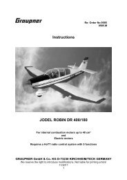
Instructions<br />
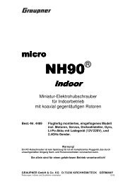
<strong>TAXI</strong> <strong>2400</strong><br />
For petrol or glowplug engines of up to 26 cc capacity<br />
or<br />
GRAUPNER COMPACT 650<br />
The model requires a six-channel radio control system<br />
Specification<br />
Wingspan approx. 2390 mm<br />
Overall length approx. 1170 mm<br />
Wing area approx. 105 dm²<br />
All-up weight according to fittings approx. 7400 g<br />
Longitudinal dihedral 0 to + 0.5º<br />
1<br />
to Order No. 9378<br />
9378.M<br />
Caution: This model is not a toy!<br />
If you are a beginner to this type of powered model, please ask an experienced model flyer for help<br />
and support. If you attempt to operate the model without knowing what you are doing, you could easily<br />
injure yourself or somebody else. Please keep your safety and well-being in mind at all times.<br />
Important: before you start construction<br />
Even if you have already built a large number of RC models please read right through these<br />
instructions and check all the kit components against the parts list. We have taken great trouble to<br />
keep construction as simple as possible, without making any compromises in the area of safety.<br />
Note regarding the film covering<br />
Minor creases or bubbles may develop in the film covering due to major fluctuations in weather<br />
conditions (temperature, humidity etc.); in rare cases you may even find a slight warp in a component.<br />
These minor faults are in the nature of film-covered built-up wooden structures, and can easily be<br />
corrected using a heat gun, as commonly used for modelling.<br />
Creases: Blow warm air over the area and rub down with a soft cloth.<br />
Wing warp: Hold the panel twisted gently in the opposite direction to the warp, and apply warm<br />
air to remove the creases from the covering.<br />
Caution! do not heat the film more than is absolutely necessary. If the air or the iron is too hot, the film<br />
may melt and holes may be formed.<br />
This model is highly pre-fabricated and can be built in a very short time. However, the work which you<br />
have to carry out is important and must be done carefully. The model will only be strong and fly well if<br />
you complete your tasks competently - so please work slowly and accurately.<br />
When self-tapping screws have to be screwed into wood, apply a little white glue to prevent<br />
them shaking loose: just squirt white glue into the hole and fit the screw.
Safety notes and warnings relating to<br />
model aircraft powered by petrol and glowplug engines<br />
Be sure to read right through the instructions covering assembly and operation of your model<br />
before you attempt to operate it for the first time.<br />
These safety notes are an integral part of the building instructions. Please keep them and the<br />
operating instructions in a safe place. If you ever dispose of the model, be sure to pass them<br />
on to the new owner.<br />
Powered model aircraft are very demanding and potentially dangerous machines, and call for a<br />
high level of technical knowledge and skill from the operator, together with a responsible<br />
attitude.<br />
Powered model aircraft are not suitable for young persons under 18 years of age.<br />
Young people should only be permitted to operate this model under the instruction and<br />
supervision of an adult who is aware of the hazards involved in this activity.<br />
The operator of the model must be in full possession of his or her bodily and mental faculties.<br />
As with car driving, operating a model aircraft under the influence of alcohol or drugs is not<br />
permissible under any circumstances.<br />
Radio-controlled model aircraft may only be employed for the purpose intended by the<br />
manufacturer. They must never be used as man-carrying machines. We do not permit this<br />
model’s use in any way except as a model aircraft.<br />
A radio-controlled model aircraft can only work properly and fulfil your expectations if it is built<br />
very carefully and in accordance with the building instructions. Do not make any modifications<br />
of any kind to the design features or materials. If you wish to avoid injuring people and<br />
damaging property it is essential to be careful and painstaking at all stages of building and<br />
operating your model. Nobody would climb into a full-size light aircraft and try to fly it without<br />
completing a course of training first. Model flying is a skill which has to be learned in just the<br />
same way. We suggest that you ask for help from an experienced model flyer, or join a model<br />
club or flight training school. Your local model shop and the specialist magazines are an<br />
excellent source of information.<br />
It is fundamentally essential to set the Centre of Gravity (CG) and control surface travels<br />
correctly. Please take the trouble to adjust the model until they are exactly correct.<br />
• Radio control system: satisfy yourself that your frequency is vacant before you switch on.<br />
Check your RC system regularly, as its components eventually wear and need to be<br />
replaced or repaired. Radio interference caused by unknown sources can occur at any time<br />
without warning. If this should happen, your model will be uncontrollable and completely<br />
unpredictable. Never leave your radio control system unguarded, as other people might<br />
pick it up and try to use it. Your RC system can only work reliably if the batteries are kept<br />
fully charged.<br />
Don’t ignore our warnings. They refer to circumstances and situations which, if ignored, can<br />
result in fatal injury or permanent damage.<br />
You alone are responsible for the safe operation of your radio-controlled model and engine.<br />
If you have any questions regarding the safe operation of your RC model aircraft, please turn<br />
to your local model shop in the first instance as the staff will be pleased to help you.<br />
• Propellers and other rotating parts which are powered by an engine represent a permanent<br />
hazard, and present a real risk of injury. Don’t touch them with any part of your body. For<br />
example, a propeller spinning at high speed can easily slice off a finger.<br />
2
• Keep well clear of the rotational plane of the propeller. You never know when some part<br />
may come loose and fly off at high speed, hitting you or anybody else in the vicinity. Never<br />
touch the revolving propeller with any object.<br />
• Take care with loose clothing such as scarves, loose shirts etc. Flapping cloth can easily<br />
be sucked into the area of the propeller and then get tangled in the blades. This is<br />
extremely dangerous.<br />
• If there are passers-by or spectators at your flying site, make sure that they are aware of<br />
the dangers inherent in your activity, and insist that they keep a safe distance away (at<br />
least 5 m).<br />
• Radio-controlled models should only be flown in “normal” weather conditions, i.e. a<br />
temperature range of -5° to +35° C. More extreme temperat ures can lead to changes in<br />
battery capacity, material characteristics and other unwanted effects.<br />
• Model fuels are toxic; do not allow them to come into contact with your eyes or mouth. Fuel<br />
should always be stored in clearly marked containers, out of the reach of children.<br />
• Never run an internal combustion engine in an enclosed space such as a cellar, garage etc.<br />
Model motors produce lethal carbon monoxide gas just like full-size engines. Motors<br />
should only be run in the open air!<br />
• Adhesives and paints contain solvents which may be hazardous to health under certain<br />
circumstances. Read and observe the notes and warnings supplied by the manufacturer of<br />
these materials.<br />
• Model fuels are volatile and highly inflammable. Keep them well away from open flames,<br />
excessive heat, all possible sources of sparks and anything else which could result in a<br />
fire. Do not smoke in the immediate vicinity of fuel or fuel vapours.<br />
• Model engines produce a lot of heat. The motor and silencer in particular become very hot<br />
when running, and stay so for quite a while. Touching the hot parts can give you serious<br />
burns, so take care especially when carrying out adjustments - wear protective gloves. Hot<br />
engines can even start a fire under certain circumstances.<br />
• When the engine is running it expels hot toxic gases from the exhaust together with very<br />
hot fluid combustion residues which can burn you.<br />
• Remove all unused fuel from the fueltank and engine after every session.<br />
• Every time you intend to operate your model check carefully that it and everything attached<br />
to it (e.g. propeller, linkages, control surfaces etc.) is in good condition and undamaged. If<br />
you find a fault, do not fly the aeroplane until you have corrected it.<br />
• Model engines are usually started with the help of an electric starter, which should be fitted<br />
with the appropriate adaptor where necessary. With fixed-wing models an alternative is to<br />
use a “chicken stick” - a length of thick wooden dowel with a piece of water hose pushed<br />
over it.<br />
• Many model engines are very noisy, producing a sound level much higher than 85 dB (A),<br />
which implies that you should wear ear defenders. Never run a motor without the silencer<br />
fitted. Even with a silencer, model engines can easily disturb your neighbours. Don’t run<br />
motors when other people expect peace and quiet.<br />
• If you start your engine when the model is standing on loose or sandy ground, the<br />
propeller will suck up sand and dust and hurl it around, and it could easily get in your eyes<br />
and do damage. Wear protective goggles at such times.<br />
• Take care that the glowplug clip and the glow lead cannot get tangled in the propeller or<br />
other rotating parts. Check the throttle linkage too.<br />
3
• Take particular care when carrying the model with the engine running. Keep well clear of<br />
the rotating parts!<br />
• Be sure to keep an adequate supply of fuel in the tank. Don’t continue to fly the model until<br />
the tank is drained dry.<br />
• Never fly directly over people.<br />
• Never fly directly towards people.<br />
• Keep a safe distance from residential areas: at least 1.5 km “as the crow flies”. The best<br />
solution is to join a model flying club and use the approved flying site. Always keep well<br />
clear of high-tension overhead cables.<br />
• Whenever you are working on the motor, make sure that you are on a safe surface and<br />
cannot slip. Get used to holding the model really securely.<br />
• Take-off and landing strips should be kept free of people and movable obstacles,<br />
particularly when a model is using the runway.<br />
• Watch the model constantly while it is in the air. Model aeroplanes must always give way to<br />
full-size aircraft.<br />
• Don’t operate your model from residential areas, public roads, squares, school<br />
playgrounds, public parks or sports grounds etc., and ensure that you always have the<br />
model under control.<br />
• It is important that you can stop your engine at any time. This is achieved by adjusting the<br />
throttle so that the barrel closes completely when you move the throttle stick and trim to<br />
their end-points. If this does not work, pinch the fuel feed line between your fingers or pull<br />
it off the carburettor. Never try to stop the engine by grasping the flywheel, propeller or<br />
spinner!<br />
• All model flyers should behave in such a way that the danger to people and property is<br />
minimised. Never act in any way which will disturb other flyers and prevent safe, orderly<br />
flying at the site.<br />
In legal terms our models are classed as aircraft, and as such are subject to legal regulations<br />
and restrictions which must be observed.<br />
Our brochure “Luftrecht für Modellflieger” (Aviation Law for Model Flyers) is available under<br />
Order No. 8032, and contains a summary of all these rules. Your local model shop will have a<br />
copy which you can read. Models fitted with internal combustion engines may only be flown<br />
with the landowner’s permission, and third party insurance is mandatory. There are also Post<br />
Office regulations concerning your radio control system, and these must be observed at all<br />
times.<br />
Please don’t misunderstand the purpose of these notes. We only want to make you aware of<br />
the many dangers and hazards which can arise if you lack knowledge and experience, or work<br />
carelessly or irresponsibly. If you take reasonable care, model flying is a highly creative,<br />
instructive, enjoyable and relaxing pastime.<br />
This model aircraft is highly pre-fabricated and can be built in a very short time. However, the<br />
work which you have to carry out is important and must be done carefully. The model will only<br />
be strong and fly well if you complete your tasks competently - so please work slowly and<br />
accurately.<br />
4
Important safety notes<br />
You have acquired a kit which can be assembled into a fully working RC model when fitted out with<br />
suitable accessories. However, we as manufacturers have no control over the way you build and<br />
operate your RC model aircraft, nor how you install, operate and maintain the associated components,<br />
and for this reason we are obliged to deny all liability for loss, damage or costs which are incurred due<br />
to the incompetent or incorrect use and operation of our products, or which are connected with such<br />
operation in any way. Unless otherwise prescribed by binding law, the obligation of the GRAUPNER<br />
company to pay compensation, regardless of the legal argument employed, is excluded. This includes<br />
personal injury, death, damage to buildings, damage due to loss of business or turnover, interruption<br />
of business or other direct or indirect consequent damage whose root cause was the operation of the<br />
model.<br />
The total liability in all cases and under all circumstances is limited to the amount of money which you<br />
actually paid for the model.<br />
This model aeroplane is built and flown at the sole and express responsibility of the operator.<br />
The only way to avoid injury to persons and damage to property is to handle and operate the<br />
model with the greatest care and consideration at all times.<br />
Before you fly the model for the first time you must check whether your private third party liability<br />
insurance policy covers you for operating model aircraft of this type. If you are not sure, take out a<br />
special policy designed to cover modelling risks.<br />
These safety notes must be kept in a safe place. If you ever dispose of the model, be sure to pass<br />
them on to the new owner.<br />
Guarantee terms<br />
The guarantee covers replacement of any parts which can be shown to exhibit manufacturing faults or<br />
material defects within the guarantee period of 24 months from the initial date of purchase. No other<br />
claims will be considered. Cost of transport, packing and freight are payable by the purchaser. We<br />
accept no liability for damage in transit. When you send the product to GRAUPNER, or to the<br />
approved Service Centre for your country, you must include a clear and concise description of the fault<br />
together with the invoice showing the date of purchase. The guarantee is invalid if the component or<br />
model fails due to an accident, incompetent handling or incorrect usage.<br />
The following points are important and must be observed at all times:<br />
• Before you fly the model, check that the radio control system is working reliably, and that all<br />
connections are secure.<br />
• If you are using dry batteries as an energy source, note that they must never be recharged. Only<br />
batteries marked specifically as ‘rechargeable’ may be recharged safely.<br />
• It is essential to charge the batteries and check the range of your radio control system before you<br />
operate the model. In particular, the radio control system batteries must be fully charged before<br />
each session.<br />
• Ensure that the channel you intend to use is not already in use by other modellers. Never fly the<br />
model if you are not certain that your channel is free.<br />
• Read and observe the instructions and recommendations provided by the manufacturer of your<br />
radio control system and accessory components.<br />
• Ensure that the servos are not mechanically obstructed at any point in their travel.<br />
• Dry cells and rechargeable batteries must never be short-circuited.<br />
• Remove all batteries from the model prior to transporting and storing it.<br />
• Do not subject the model to dirty or cold conditions, or high levels of humidity or heat.<br />
• Secure the model and your RC equipment carefully when transporting them. They may be<br />
seriously damaged if they are free to slide about.<br />
Pre-flight checks<br />
Check that the radio control system works correctly and at full range before every flight: switch on the<br />
transmitter and the receiving system, but leave the transmitter aerial collapsed. Walk away from the<br />
model, and check that all the control surfaces work smoothly and immediately at an appropriate<br />
distance, and deflect in the correct “sense” (direction) relative to the stick movements.<br />
Repeat the checks with the motor running, while a friend holds the model firmly for you.<br />
If you are a relative beginner to model flying, we recommend that you enlist an experienced model<br />
pilot to help you check and test-fly the model.<br />
5
Care and maintenance<br />
• Clean the model carefully after every flight, and remove any dirt from the propeller. Clean the<br />
model and RC components using suitable cleaning agents only. Ask your model shop for<br />
information.<br />
• If the model is not to be run for a considerable time it is important to clean and re-lubricate all the<br />
moving parts.<br />
Notes on completing the model<br />
• Before building the model it is important that you read the instructions right through to the end.<br />
Use the parts list constantly as an aid to construction. The instructions and parts list reflect the<br />
sequence of assembly.<br />
• Tools can be dangerous; be aware of the hazards involved in using them.<br />
• Use cable of adequate cross-section, capable of carrying the currents which will flow when the<br />
model is flying.<br />
• Install the receiver aerial well away from any high-current leads (min. distance 3 cm).<br />
• Before making any glued joints, be sure to clean the surfaces and remove all traces of grease. We<br />
recommend sanding lightly, or wiping with a non-greasy cleaning agent. The same applies to<br />
surfaces to be painted, otherwise the paint is unlikely to adhere well. Before gluing parts to the<br />
fuselage it is essential to roughen the surfaces with fine abrasive paper and de-grease them with<br />
acetone or similar solvent, otherwise you will not obtain strong, durable joints. This applies in<br />
particular to moulded GRP fuselages.<br />
Additional items required<br />
Engine and accessories<br />
Engine<br />
Order No.<br />
OS MAX 160 FX<br />
1923<br />
OS MAX FS 120<br />
SURPASS<br />
four-stroke<br />
1886<br />
OS MAX FS 120<br />
SURPASS-E<br />
four-stroke<br />
1848<br />
OS MAX FT-160<br />
1412<br />
G26<br />
petrol engine<br />
1903<br />
Capacity Silencer Propeller<br />
cc<br />
Order No. Order No.<br />
26.23 1839.33 38 x 20 cm<br />
1318.38.20<br />
19.96 1886.33 36 x 15 cm<br />
2960.36.15<br />
19.96 1886.33 36 x 15 cm<br />
2960.36.15<br />
2 x 13.26 2x1499.33 45 x 20 cm<br />
2960.45.20<br />
26 1556 45 x 20 cm<br />
2960.45.20<br />
6<br />
Manifold<br />
Order No.<br />
Not required<br />
Included<br />
with silencer<br />
Included<br />
with silencer<br />
1001.145<br />
2 x required<br />
1556.2 with<br />
Teflon hose<br />
1556.3 and<br />
spring<br />
clamps<br />
1556.4<br />
Radio control system<br />
For this model you require a six-channel RC system with eight servos. The transmitter should<br />
also feature a servo reverse facility.<br />
We particularly recommend: mc-22 to mc-24 computer systems. The model is designed for standardsize<br />
servos.<br />
We recommend the following receiver battery: SANYO 4KR-1800 SCE, Order No. 3201, which should<br />
be properly maintained before and after each flying session, i.e. the pack needs to be cycled (charged<br />
and discharged) several times before it reaches full rated capacity.<br />
For connecting the two aileron servos to the receiver you will need two suppressor filters, Order No.<br />
1040, or a folding ferrite ring, Order No. 98516, plus two extension leads, Order No. 3935.11.
Extension leads required:<br />
Servo No. off Order No.<br />
Aileron servo 2 leads 3935.50<br />
Landing flap servo 2 leads 3935.18<br />
Elevator servo 2 leads 3935.105<br />
Throttle servo 1 lead 3935.32<br />
For connecting the extension leads to the receiver: four extension leads, 3935.11.<br />
Foam padding for packing round the receiver and battery: included in the kit.<br />
The model is suitable for standard-size servos, e.g. Order No. 3916.<br />
Adhesives<br />
Fast-setting epoxy resin, e.g. UHU plus schnellfest, Order No. 962<br />
Slow-setting epoxy resin, e.g. UHU plus endfest 300, Order No. 950<br />
White glue, e.g. UHU coll, Order No. 958.60<br />
UHU hart (cellulose cement), e.g. Order No. 534<br />
Cyano-acrylate glue (“cyano”), e.g. Order No. 5821<br />
Thread-lock fluid, e.g. Order No. 952<br />
Accessories for flying the model with a glow motor (not included)<br />
Synthetic oil based glow fuel, to suit motor<br />
Fuel filter, e.g. Order No. 1650.1<br />
Fuel tubing, e.g. Order No. 1643<br />
Manual fuel pump, e.g. Order No. 1610<br />
Glowplug energizer battery and glowplug clip, e.g. Order No. 3252<br />
Electric starter, e.g. Order No. 1628<br />
Starter battery, e.g. Order No. 2592<br />
Accessories for flying the model with a petrol engine (not included)<br />
Fuel (see engine operating instructions)<br />
Fuel filter, e.g. Order No. 1646<br />
Fuel tubing, e.g. Order No. 1325.2<br />
Fuel pump, e.g. Order No. 6870<br />
Tools required (not included)<br />
Various (cross-point) screwdrivers, pointed-nose pliers, flat-nose pliers, side-cutters, balsa knife or<br />
razor blade, set of twist drills, universal glowplug spanner, Z-bend pliers, Order No. 5732, soldering<br />
iron, pencil or felt-tip pen.<br />
Assembling the <strong>TAXI</strong> <strong>2400</strong><br />
Please don’t start building the model until you have read right through the building instructions and are<br />
familiar with all the model’s components. If you are not satisfied with any part, inform your supplier<br />
before you start work on the model.<br />
Work on the wing panels<br />
This is limited to installing the servos and linkages in the wing panels, and attaching the landing flap<br />
hinges.<br />
Remove one side of the double-ended servo output levers using side-cutters, and sand the cut edges<br />
smooth, as shown in the photo.<br />
Use your fingers to locate the slots in the servo plates and the holes in the underside of the wing<br />
panels close to the root ribs, and melt away the covering film using a hot soldering iron. The servo<br />
extension leads can now be threaded through the wing. Each of the procedures described below<br />
should be repeated with the second wing panel.<br />
Set the aileron servo to centre from the transmitter, i.e. connect the servo, receiver battery and switch<br />
harness to the receiver, then switch on the transmitter and receiver. Check that the trims are at centre.<br />
The servo is now at neutral (centre).<br />
Attach the servo to the mounting blocks using the retaining screws supplied with it. Remember to<br />
press the rubber grommets and brass tubular spacers (flange at the bottom) into the mounting lugs<br />
beforehand. Drill pilot-holes for the screws, working through the tubular spacers. You will find it easier<br />
to fit the metal spacers if you thread them onto a screwdriver first.<br />
7
The servo extension leads can now be drawn through the wing panels. First connect the servo cable<br />
to an extension lead, and secure the connection using a heat-shrink sleeve (supplied).Tie a length of<br />
thread to the lead close to the plug, and use it to pull the wire through the wing panel.<br />
Place the servo plate in the recess in the wing, with the servo output arm facing the wingtip.<br />
Drill pilot-holes in the four corners of the servo plate, and secure it using four self-tapping screws.<br />
Position the horn on the aileron so that the pushrod runs parallel to the servo; the linkage hole of the<br />
horn should also be at right-angles to the hinge pivot axis of the aileron. Drill pilot-holes through the<br />
aileron for the retaining screws. Tack the horn to the aileron in the correct position with a drop of<br />
cyano.<br />
The horn can now be attached to the aileron using the M2 x 30 pan-head screws and spreader plate<br />
supplied.<br />
Adjust the length of the horn so that the linkage hole is about 20 mm above the aileron.<br />
Cut off excess screw length using side-cutters, and sand the cut ends back flush with the spreader<br />
plate. Repeat the process with the M3 hex-head bolt which forms the horn column.<br />
Each aileron pushrod consists of an M3 clevis, an M2.5 clevis and a length of M2.5 studding (threaded<br />
rod). The length of the pushrod is dictated by the position of the servo and the horn.<br />
Screw an M2.5 clevis onto the threaded rod (M2.5 x 80 mm), and connect it to the servo output arm.<br />
Connect the M3 clevis to the horn, set the aileron and servo to neutral, and mark the correct length of<br />
the pushrod. Cut the rod to length.<br />
Fit the M3 clevis on the threaded rod and solder the joint.<br />
The landing flap linkages can be installed using the same procedure as for the ailerons, except that<br />
the horns have to be attached to the front face of the flaps, and the hinges are mounted externally, as<br />
shown in the photos.<br />
When mounting the flap servos on the servo plates please note that the servo output arms must face<br />
inward, instead of projecting out of the plates.<br />
The next step is to install the flap hinges. First tape the flap to the wing (important: the flap must be at<br />
neutral, or even slightly negative (up)). Align the hinges carefully using the edge of a ruler, as shown in<br />
the photo, then mark the position of the screw-holes on the wing. Drill the holes as accurately as you<br />
can.<br />
Three hinges are required for each landing flap. The exact position of the flaps is dictated by the<br />
hardwood reinforcements in the flaps and wings.<br />
The location of the flap horn is dictated by the position of the servo in the wing. Drill a 6 mm Ø hole at<br />
the appropriate point (centre of the front face of the flap).<br />
Screw the aluminium horn into the hole to the point where the distance between the linkage hole and<br />
the front face of the flap is 11 mm.<br />
Assemble the flap pushrod as described for the ailerons. The servo output arm and pushrod should be<br />
adjusted so that the flaps can be deflected to maximum travel.<br />
The servo can now be mounted in the wing using the servo mounts supplied.<br />
Connect the clevis to the flap horn and adjust it so that the servo is not stalled, i.e. draws no current,<br />
when the flap is fully retracted.<br />
Installing the elevator servos in the tailplane panels<br />
The elevator servos are installed in the tailplane panels as described for the aileron servos.<br />
Locate the opening for the servo plate with your fingers, and melt away the film using a hot soldering<br />
iron.<br />
Fit the servo in the mounts, assemble the pushrod and install the mount in the tailplane panel. Repeat<br />
with the second tailplane panel.<br />
As with the wings, the location of the elevator horn is dictated by the position of the servo output arm.<br />
The horn should be fitted with the linkage hole at right-angles to the elevator hinge pivot axis.<br />
Install the horn and pushrod as shown in the photos.<br />
8
The tailplane panels are held against the fuselage by a retainer system, for which the M6 knurled nuts<br />
must be glued in the root face of both panels. Adjust the yoke and wedge of the retainer so that the<br />
root ribs are held firmly against the fuselage when the retainer is fully engaged.<br />
Installing the fin<br />
To fit the fin you must first melt away the covering film over the slot in the fuselage. Locate the slot<br />
with your fingers and run a hot soldering iron along the edges.<br />
Slide the fin into the slot, and mark a line along the outside contour of the fuselage with a felt-tip pen.<br />
Remove the covering film just inside the marked lines using a soldering iron, and peel the film away<br />
from the wood.<br />
Apply glue to the fin and the slot, then slide the fin into place; either UHU coll (white glue) or UHU<br />
endfest (slow-setting epoxy) can be used for this joint. Check that the fin is exactly vertical, and pin it<br />
in position while the glue is setting.<br />
Installing the tailwheel unit<br />
The steerable tailwheel unit is attached to the underside of the tail end of the fuselage using two panhead<br />
self-tapping screws.<br />
The steerable tailwheel is operated by means of braided steel cables. Drill and file out two slots in the<br />
underside of the fuselage, following the dimensions stated in the photo, and glue pieces of plastic<br />
sleeve in them to guide the steering cables.<br />
Crimp the steel cables to the tailwheel steering arms and the rudder horns as shown in the photos,<br />
and solder the cables on both sides of the aluminium crimp sleeves. The two rudder horns are<br />
attached to the rudder using three M2 screws and three self-locking nuts.<br />
Bundle together the pairs of steel cables from the rudder and tailwheel unit, and crimp them to single<br />
clevises at the rudder servo.<br />
Mount the receiver, receiver battery and ignition battery (petrol engine only) on the plate as shown in<br />
the photo.<br />
Installing the main undercarriage units<br />
Attach the undercarriage units to the fuselage using the retaining screws supplied.<br />
Apply a drop of UHU thread-lock fluid to the screws to prevent them shaking loose.<br />
Drill the holes for the wheel axles in the wheel spats (note that the spats are handed, i.e. different left<br />
and right).<br />
The hole in the outside of the spat must be drilled 4 mm Ø, that on the inside 8 mm Ø.<br />
Glue the plywood reinforcements in the wheel spats.<br />
Allow the glue to set hard, then mount the wheel spats, wheels and wheel axles on the undercarriage<br />
units as described below.<br />
Fit the wheel axles in the wheel spats with the hexagon shoulder resting against the ply reinforcement.<br />
Mark the length of the wheel axle with a felt-tip pen; it should project by about 1.5 mm on the outside<br />
of the wheel spat.<br />
Now slip the wheel and two collets (collet / wheel / collet) on the wheel axle, and fit this assembly in<br />
the wheel spat, threading the axle through the holes. You will need to spread the spat slightly to allow<br />
the axle to engage in the holes.<br />
The wheel axles can now be screwed to the undercarriage legs. Apply a drop of thread-lock fluid to the<br />
nuts to prevent them shaking loose.<br />
9
Installing the petrol engine<br />
These instructions only describe the method of installing the G 26 petrol engine, but the procedure is<br />
the same for any other suitable power plant.<br />
The first step is to screw the engine to the mount. Note that the distance between the rear face of the<br />
motor mount and the front face of the propeller driver should be about 156 mm. Mark the position of<br />
the screw-holes on the mount arms, then drill holes for the retaining screws.<br />
Fix the engine to the mount arms using the retaining screws supplied.<br />
Place the mount assembly on the nose bulkhead and position the centreline of the engine over the<br />
centre of the marked lines.<br />
In this position mark and drill the holes for the mount retaining screws on the engine bulkhead, using a<br />
size of bit which fits snugly in the mount holes.<br />
Alternatively the engine can be mounted on vibration absorbers, Order No. 6853.5; in this case the<br />
holes in the nose bulkhead will need to be enlarged to accept the rubber dampers.<br />
The throttle servo can either be installed in the fuselage or directly behind the engine on the nose<br />
bulkhead (see photos).<br />
The right-hand picture shows an M3 socket-head cap screw screwed into the throttle lever. This is<br />
used to hold the choke flap closed, so that petrol is drawn through to the engine. The choke flap is<br />
opened again by opening the throttle briefly from the transmitter.<br />
Mount the exhaust manifold and silencer on the engine using the socket-head cap screws supplied.<br />
The silencer is connected to the manifold using Teflon hose and spring clamps. Cut and file out the<br />
holes in the cowl to clear the silencer, needle valve, etc.<br />
The cowl is attached to the fuselage using pan-head self-tapping screws fitted above and below the<br />
side cheeks.<br />
Assembling and installing the fueltank<br />
Your choice of fueltank varies according to the type of engine you have installed. If you have fitted a G<br />
26 petrol engine, use the small tank supplied, with the appropriate (petrol-proof) fuel tubing. For a glow<br />
motor the slightly larger tank shown below should be used.<br />
Push a length of fuel tubing onto the fueltank clunk weight. Push the free end of the fuel tubing onto<br />
one of the tubes in the fueltank stopper, and check that the clunk will be able to move freely inside the<br />
tank without binding or jamming when the stopper is in place. Soften the other two tubes (filler and<br />
vent) using a heat-gun or match, and bend them to the shape shown in the photo; one should point<br />
down (later used for filling the tank), the other up (overflow line).<br />
Now push the tank stopper over the neck of the fueltank and clamp it in place by tightening the crosshead<br />
screw. It is important to tighten the screw to the point where the tank is completely sealed. You<br />
can check this with a water test: hold the tank under water, seal two tubes and blow into the third: any<br />
bubbles indicate a leak which must be corrected.<br />
Push pieces of fuel tubing onto the tubes where they exit the fuel stopper.<br />
Mark the fuel lines using a felt-tip pen to indicate which is the fuel feed, the overflow and the filler.<br />
Fit the fueltank into the fuselage through the wing saddle, threading the three fuel tubes through the<br />
hole in the nose bulkhead.<br />
Glue a strip of wood across the fuselage sides behind the fueltank to ensure that it cannot shift<br />
backwards in flight.<br />
Connecting the fuel lines<br />
Locate the fuel line attached to the fueltank clunk weight (fuel feed) and connect it to the carburettor<br />
inlet nipple. Connect the overflow line to the pressure nipple on the silencer. For the filler line we<br />
recommend that you drill a 5 mm Ø hole in the right-hand side of the cowl. The filler tube is later<br />
slipped through this hole and sealed with a sealing nipple, Order No. 140, before take-off.<br />
Position of receiver, battery and switch<br />
Install the receiver, receiver battery and switch in the fuselage in the positions shown in the photo.<br />
10
Assembling the <strong>TAXI</strong> <strong>2400</strong><br />
Fit the wing panels together on the aluminium joiner tube.<br />
To connect the aileron servos to the receiver we recommend using two 100 mm extension leads,<br />
connected permanently to the appropriate receiver output sockets (2 and 5).<br />
Connect the aileron servos to the extension leads attached to the receiver, then place the wing on the<br />
wing saddle and fit the four metal screws to attach it to the fuselage.<br />
Don’t over-tighten the screws; tighten them just to the point where the wing is held securely on the<br />
fuselage and cannot move.<br />
Fit the tailplane panels on the aluminium joiner tube and push them up against the fuselage so that the<br />
retaining wedge engages fully in the yoke. Check that the retainer system holds the tailplane reliably<br />
against the fuselage.<br />
Balancing the <strong>TAXI</strong> <strong>2400</strong><br />
With the fueltank empty, support the model under both wing roots at a point about 120 - 125 mm aft of<br />
the wing leading edge. If the CG position is correct the model will hang level, with the nose inclined<br />
slightly down. If necessary glue lead ballast to the nose or tail to obtain the correct balance. All the<br />
control surfaces must be exactly at centre when the transmitter trims and sticks are in the neutral<br />
position. Check this before the first flight.<br />
Control surface travels for normal flying<br />
Ailerons 30 mm up, 28 mm down<br />
Elevators 25 mm up, 25 mm down<br />
Rudder 50 mm right, 50 mm left<br />
Landing flaps and elevator trim for landing:<br />
Flaps max. = 60°, 6 mm down-elevator<br />
The stated travels should only be considered as a starting point; you may well find it necessary to<br />
adjust them to suit your personal preference.<br />
We recommend setting 35° exponential (expo) on all control systems at the transmitter.<br />
Important:<br />
When fitting and adjusting the various linkages you should ensure that they move freely, without<br />
binding, are able to move to their full extent - including trim travel - and are not obstructed<br />
mechanically at any point.<br />
When you move the rudder stick to the right, the rudder should also deflect to the right (left stick: left<br />
rudder). Pull the elevator stick back towards you, and the elevators must both deflect up (stick forward:<br />
elevators down). If you move the aileron stick to the right, the right aileron should rise, the left aileron<br />
fall. When you move the throttle stick forward, the motor should run to the full-throttle position, i.e. the<br />
carburettor barrel should be fully open.<br />
We recommend that you assign the landing flaps to a switch, and program the correct travel at the<br />
transmitter.<br />
Finally - we hope you have many hours of fun and pleasure flying your <strong>TAXI</strong> <strong>2400</strong>.<br />
Yours - the <strong>Graupner</strong> team<br />
GRAUPNER GmbH & Co. KG D-73230 KIRCHHEIM/TECK GERMANY<br />
We reserve the right to introduce modifications. No liability for printing errors. 06/2005<br />
Made in Vietnam<br />
11