
You also want an ePaper? Increase the reach of your titles
YUMPU automatically turns print PDFs into web optimized ePapers that Google loves.
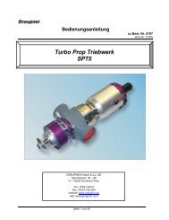
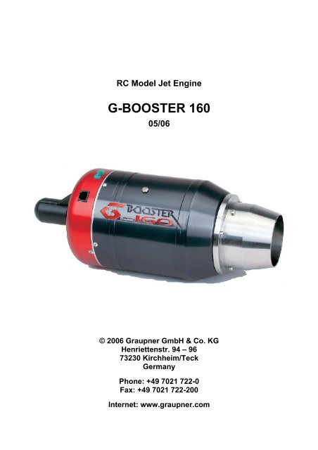
RC Model Jet Engine<br />
G-BOOSTER 160<br />
05/06<br />
© 2006 <strong>Graupner</strong> GmbH & Co. KG<br />
Henriettenstr. 94 – 96<br />
73230 Kirchheim/Teck<br />
Germany<br />
Phone: +49 7021 722-0<br />
Fax: +49 7021 722-200<br />
Internet: www.graupner.com
Inhaltsverzeichnis<br />
GRAUPNER G-BOOSTER 160 – Manual 1.91<br />
Introduction ....................................................................................................................... 3<br />
Warnings and Safety Notes .............................................................................................. 4<br />
Warranty Conditions.......................................................................................................... 7<br />
Technical Specifications.................................................................................................... 8<br />
Installation Plan.................................................................................................................. 9<br />
Checklist for the First Operation..................................................................................... 10<br />
Checklist for Turning the Engine Off.............................................................................. 10<br />
EDT Status Display (Engine Data Terminal)................................................................... 11<br />
JETRONIC-Vx – Firmware Setup..................................................................................... 13<br />
1:INFO Menu .................................................................................................................... 14<br />
2:STATISTICS Menu ........................................................................................................ 18<br />
3:LIMITS Menu ................................................................................................................. 20<br />
4:AUTOSTART Menu ....................................................................................................... 22<br />
5:R/C-SETTINGS Menu .................................................................................................... 24<br />
6:TEST-DEVICES Menu ................................................................................................... 27<br />
Airspeed Sensor............................................................................................................... 30<br />
2
Introduction<br />
GRAUPNER G-BOOSTER 160 – Manual 1.91<br />
The model jet engine GRAUPNER G-BOOSTER 160 has the same functional principle as a "big"<br />
jet engine. A single-stage radial compressor compresses ingested air, which is then heated by a<br />
fuel flame in the combustion chamber. The heat causes the air to expand rapidly, enabling it to<br />
drive an axial turbine rotor, which in turn drives the aforementioned compressor via a shaft<br />
(bootstrap cycle).<br />
At the exhaust cone, the hot air leaves the engine at a speed of more than 1000 km/h (620 mph),<br />
generating the required thrust for the jet aircraft model. An electric starter motor and an electric<br />
kerosene ignition system allow fully automated engine control from the R/C transmitter, controlled<br />
and monitored by the JETRONIC control unit, which regulates all operating parameters to their<br />
optimal values. This new generation of model jet engines does not require auxiliary gases like<br />
propane or butane any more. Power is supplied to the engine by a separate rechargeable battery,<br />
which is used to power all system components, such as fuel pump, kerosene ignition, valves etc.<br />
The jet engine GRAUPNER G-BOOSTER 160 has almost the same weight and dimensions as its<br />
predecessors, yet delivers a significantly higher thrust (about 160 N).<br />
State-of-the art precision CNC and laser cutting technology allow a previously impossible<br />
production accuracy, ensuring both high performance and durability. The included display and<br />
programming unit (EDT = Engine Data Terminal) is equipped with an illuminated alphanumeric<br />
display and can be connected to (and disconnected from) the running system at any time to check<br />
the current operating data or to change parameters. Besides the current operating parameters,<br />
such as exhaust gas temperature (EGT), turbine revolutions per minute (rpm) and thrust (throttle),<br />
additional information like total hours of operation, rpm and temperature statistics, number of<br />
engine starts, battery voltage etc. can be displayed as well.<br />
All parameters and user entries are displayed in plain text in a menu-based interface. The turbine<br />
is started fully automatically via the throttle stick on the R/C transmitter. The pilot then adjusts the<br />
desired thrust by moving the stick proptionally. The JETRONIC control unit is connected to the R/C<br />
receiver via R/C-1, R/C-2 can be connected optionally for switching functions.<br />
3
GRAUPNER G-BOOSTER 160 – Manual 1.91<br />
IMPORTANT NOTE:<br />
Operating a jet aircraft model requires greatest care and special knowledge. When<br />
installing and operating your jet engine, always observe the safety rules in this manual!<br />
Warnings and Safety Notes<br />
Welcome to the era of model jet aircraft! Please never forget: Operating a jet engine like the<br />
G-BOOSTER 160 can be dangerous. An aircraft model equipped with the G-BOOSTER 160 can<br />
reach speeds of more than 400 km/h (250 mph) and temperatures up to 500 °C (930 °F) at the<br />
engine housing and up to 750 °C (1380 °F) at the exhaust jet. Since it is a genuine jet engine, it<br />
requires know-how, discipline and regular service and maintenance – for your own protection and<br />
that of other people. If you want to install and operate this jet engine in your model aircraft, you<br />
mus be trained in its handling. The model with the jet engine should only be operated under supervision<br />
of an experienced person, who can support you in order to avoid mistakes. If there is a local<br />
R/C club in your area offering training and support, we recommend that you become a member.<br />
Mistakes made during the assembly or operation of a jet-powered model aircraft can lead to<br />
serious injuries or even death.<br />
Always observe the law<br />
Before operating a model aircraft with this jet engine, you should be informed about the legal<br />
regulations regarding such aircraft. From a legal point of view, a model aircraft is considered an<br />
aircraft like any other in most countries and is subject to the corresponding laws, which must be<br />
observed by all means. Please check the applicable air traffic laws of your country carefully before<br />
flying your model. Your local R/C club will likely be able to provide you with the required information<br />
and documents. In many countries, jet-powered model aircraft require a special licence<br />
and/or a special insurance. Furthermore, regulations regarding the protection against interference<br />
between R/C transmitters and radio networks must be observed. Please make sure to comply with<br />
all applicable laws and regulations in your country.<br />
CAUTION – keep a safe distance!<br />
It is your responsibility to protect others against injuries. The operating distance of your aircraft<br />
from residential areas must be at least 1.5 km (1 mile) in order to ensure the safety of people,<br />
animals and buildings. Keep a safe distance from power lines. Never fly your model in bad weather<br />
with low clouds or fog. Never fly directly against the sunlight – otherwise you might lose visual<br />
contact with your model. To avoid collisions with manned or unmanned aircraft, land your model<br />
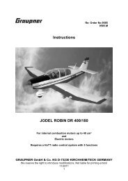
immediately if an aircraft is approaching. Persons and animals must keep the following minimum<br />
distance to the jet engine (see also the figure on page 6):<br />
In front of the engine: 1 m (3 ft)<br />
At the sides of the engine: 12 m (36 ft)<br />
Behind the engine: 10 m (30 ft)<br />
4
WARNING!<br />
GRAUPNER G-BOOSTER 160 – Manual 1.91<br />
Operating the model and/or the jet engine under the influence of alcohol, drugs etc. is strictly<br />
forbidden. The jet engine may only be handled by persons with an excellent physical and mental<br />
condition and concentration. This applies to the operator as well as any assistants.<br />
This jet engine was designed solely for use in model aircraft and is niot suitable for any other<br />
purpose. Never use it for persons, objects or vehicles other than suitably constructed model<br />
aircraft, as any other use can lead to personal injury or death.<br />
Any deviation from the specifications in this manual, the use of non-approved parts or materials or<br />
modifications to the system construction or setup can have a negative effect on the functionality<br />
and safety of the jet engine and must be avoided by all means.<br />
WARNING!<br />
The jet engine may only be operated in exact compliance with the instructions in this manual.<br />
Furthermore, the specifications of the aircraft model regarding the centre of gravity and rudder<br />
manipulations must be adhered to. The configuration recommended by the model manufacturer<br />
must be observed. Before taking off with a model equipped with this jet engine, all functions and all<br />
rudders as well as the range of the R/C transmitter must be tested with the transmiter turned on<br />
and the antenna retracted. This range test must be repeated with the jet engine running while<br />
another person is holding the model in place. Furthermore, the instructions by the R/C system<br />
manufacturer must be followed closely.<br />
Disclaimer<br />
<strong>Graupner</strong> cannot supervise the adherence to the assembly and operating instructions for the<br />
aircraft model and the jet engine, nor the installation, operation, use and maintenance of the model<br />
components. Therefore, <strong>Graupner</strong> does not assume any liability for losses, damage or costs<br />
caused by improper operation or improper behaviour or related in any other way to the<br />
aforementioned. Unless demanded by law, any liability of <strong>Graupner</strong> to pay compensation for<br />
damages for whatever reason (including personal injury, death, damage to buildings as well as<br />
loss of sales and profits, business interruption or other indirect or direct consequential loss caused<br />
by the operation of the model or the jet engine) is excluded. Under all circumstances and in any<br />
case, the joint liability is limited to the amount you actually paid for the model aircraft or jet engine.<br />
The operation of the aircraft model and the jet engine takes place solely at the operator's<br />
own risk!<br />
By operating the jet engine, you confirm to be aware of the fact that <strong>Graupner</strong> cannot supervise or<br />
control the compliance with the instructions in this manual regarding assembly, operation and use<br />
of the aircraft model, jet engine and remote control unit. From <strong>Graupner</strong>'s side, no promises,<br />
contractual agreements, guarantees or other agreements with persons or companies regarding the<br />
functionality and operation of the model and the jet engine have been made. When buying this<br />
aircraft model or jet engine, you as the operator were relying on your own expertise and<br />
judgement.<br />
5
Safety Notes<br />
GRAUPNER G-BOOSTER 160 – Manual 1.91<br />
✔ Always have a fully functional CO2 fire extinguisher with at least 2 kg (4.4 lb) of filling<br />
weight at hand.<br />
✔ Only test the jet engine at suitable places outdoor and observe the applicable laws<br />
and regulations.<br />
✔ Always keep the following safety distances from the running jet engine<br />
(1 m = 3 ft, 10 m = 30 ft, 12 m = 36 ft):<br />
✔ Never look directly into the exhaust jet and never touch it with your hands.<br />
✔ Whenever possible, wear hearing protection.<br />
✔ Keep away from the engine intake (electric starter). The air stream has an enormous<br />
suction power, which can lead to severe injuries.<br />
✔ After the first installation, and afterwards in regular intervals, test the transmission<br />
range of your R/C system with the jet engine running.<br />
✔ Before operating the engine, remove all loose objects near the engine intake, such<br />
as cleaning cloths, screws, nuts, cables or other material. Before operating your<br />
model for the first time, make sure that there are no loose objects in the engine<br />
intake, such as clippings, screws or swarf from building the model. Such objects can<br />
damage the turbine. When installing the engine in your aircraft model, cover the<br />
engine intake and exhaust opening, for example with adhesive tape, to keep<br />
clippings/swarf and other objects from entering the engine.<br />
✔ Make sure that about 5 % of turbine oil is added to the fuel. Only use special aircraft<br />
turbine oil.<br />
6
Warning:<br />
GRAUPNER G-BOOSTER 160 – Manual 1.91<br />
Compared to an ducted fan model aircraft, the model with a jet engine reaches much higher<br />
airspeeds due to the considerably higher exhaust speed at the same static thrust. The achievable<br />
airspeeds of more than 300 km/h (190 mph) normally exceed the speed range an aircraft model is<br />
approved for (risk of rudder flutter, sudden nose dives and overload of the fuselage and the<br />
servos).<br />
Therefore always take care of the following: After taking off and accelerating to normal airspeed,<br />
always pull the throttle back. For horizontal flight, 50 % of thrust is sufficient to achieve the same<br />
flight performance as with an ducted fan !<br />
Only use the full thrust of the jet engine for takeoff and for vertical climbing in aerobatics!<br />
For limiting the airspeed, we highly recommend using the optionally available airspeed sensor (part<br />
no. 6813.15)!<br />
Warranty Conditions<br />
The warranty covers the free repair or replacement of parts that exhibit proven defects of<br />
fabrication or material defects within the warranty period of 24 months from the date of<br />
purchase. Any further claims are excluded. Costs for packaging and shipping are paid by the<br />
buyer. No liability is assumed for loss during transport. When sending the defective article to<br />
<strong>Graupner</strong> or to the service contractor in charge for the respective country, a detailed description<br />
of the fault and the invoice stating the date of purchase must be included. The warranty is void if<br />
the defect of the part or the model is caused by an accident, improper handling or improper use.<br />
Removing or damaging the safety seal on the cover of the jet engine voids the warranty.<br />
7
Technical Specifications<br />
<strong>Graupner</strong> G-Booster 160<br />
GRAUPNER G-BOOSTER 160 – Manual 1.91<br />
Max. thrust: 160 N (36lb) at 15 °C (60 °F) and 1013 hPa<br />
Diameter: 112 mm (4.4")<br />
Length incl. starter: 288 mm (11.3")<br />
Weight: 1450 g (3.2 lb)<br />
Rotor speed: 30,000 – 123,000 rpm<br />
Turbine rotor: Inconel 70 mm (2.8")<br />
Mass flow: approx. 0.39 kg/s (0.86 lb/s)<br />
Jet speed: max. 1650 km/h (1025 mph)<br />
Fuel consumption: approx. 410 ml/min. (14 fl.oz/min.)<br />
Fuel type: Jet A1 / kerosene, approved fuel<br />
with 5 % turbine oil, e.g. AEROSHELL 500<br />
Maintenance interval: 50 hours or 300 million revolutions<br />
See also 24:JET-ENGINE (page 19)<br />
Status: May 2006<br />
8
Installation Plan<br />
GRAUPNER G-BOOSTER 160 – Manual 1.91<br />
9
GRAUPNER G-BOOSTER 160 – Manual 1.91<br />
Checklist for the First Operation<br />
✔ Install and connect the components according to the installation plan (see page 9). Pay<br />
special attention to the correct connection of the FUELvalve (red ring) and the STARTvalve<br />
and to a proper laying of the tubes without crimping them. An arrow on the fuel pump<br />
indicates the flow direction to the engine.<br />
✔ The QS quick connectors (blue) should snap in when you plug in the tube. The tube can<br />
only be released by pressing on the blue ring while pulling the tube out. Only use approved<br />
PUN tubes with a diameter of 3 mm (0.12") or 4 mm (0.16"), respectively.<br />
✔ Adjust the temperature sensor to the environment temperature via the parameter<br />
AUTOSTART 47:EGT/AMBIENT (see page 23).<br />
✔ Teach-in the remote control: OFF, IDLE, 100 %, via the R/C-SETTINGS parameters 51, 52,<br />
53 (see page 25).<br />
✔ Charge all batteries, paying special attention to the correct charging program for the lithium<br />
battery, i.e. a maximum charging voltage of 12.60 V (4.20 V per cell).<br />
✔ Open the fuel tank ventilation, then fill the fuel tank(s) with fuel containing approx. 5 % of<br />
oil, i.e. one can of turbine oil in 20 litres (5.3 US gallons) of kerosene.<br />
✔ Have a CO2 fire extinguisher at hand!<br />
✔ Turn on the R/C transmitter, then turn on the receiver.<br />
✔ Place your aircraft model with the nose against the wind.<br />
✔ Start the jet engine (keep a safe distance, see page 6!):<br />
1. Trimming down + throttle down => remove LOCK<br />
2. Trimming up => RUN – cleared<br />
3. Throttle up and down again => AUTOSTART activated, see EDT display (page 11).<br />
Checklist for Turning the Engine Off<br />
✔ Place the aircraft model with the nose against the wind.<br />
✔ Turn the jet engine off: trimming down + throttle down => -OFF<br />
✔ Wait until the automatic cool-down procedure of the engine is finished.<br />
✔ Check the INFO data about the operating states (see page 14 ff).<br />
✔ After finishing the flight activities, remove all fuel from the tank(s) and close the fuel tank<br />
ventilation.<br />
10
GRAUPNER G-BOOSTER 160 – Manual 1.91<br />
EDT Status Display (Engine Data Terminal)<br />
TH: = Throttle is a combined function display and error display for the engine operation.<br />
Function display – example for a standard start-up procedure:<br />
TH:lock → Remote control locked – to unlock it, pull the throttle and the trimming<br />
all the way back. See also 51:RC1-TRIM.OFF (page 25).<br />
TH:stop →<br />
TH:run- →<br />
TH:rel- →<br />
TH:fire →<br />
TH:spin →<br />
TH:heat →<br />
TH:acce →<br />
TH:cal. →<br />
Remote control unlocked – engine off – to turn it on, push the trimming<br />
up. See also 52:RC1-IDLE (page 25).<br />
Engine on – for a further check, push the throttle forward.<br />
See also 53:RC1-100% (page 25).<br />
Check complete – to start the turbine, pull the throttle back to the IDLE<br />
position within 10 seconds.<br />
The electric starter confirms the starting procedure by turning briefly.<br />
Preheating of the kerosene igniter, this takes about 5 to 15 seconds.<br />
Spin-up via the electric starter and fuel ignition.<br />
See also 40:SPINUP/FIRE (page 23).<br />
Heat-up phase of the kerosene igniter and the combustion chamber.<br />
See also 44:HEAT-UP (page 23).<br />
Acceleration of the turbine to normal operation.<br />
See also 43:ACCE-RAMP (page 23).<br />
Calibration of the fuel pump and the fuel supply system.<br />
TH:idle100% Thrust available to the pilot. Ready for takeoff!<br />
11
TH:-off →<br />
TH:cool →<br />
GRAUPNER G-BOOSTER 160 – Manual 1.91<br />
To turn off the engine, pull the throttle and the trimming all the way back.<br />
The engine enters a controlled cool-down phase to ensure a long life of the<br />
high-performance bearings.<br />
The error codes are explained under Firmware Setup 19:LAST-OFF on page 16/17.<br />
12
GRAUPNER G-BOOSTER 160 – Manual 1.91<br />
JETRONIC-Vx – Firmware Setup<br />
SETUP Menu<br />
To enter the SETUP menu for configuring the firmware parameters, first press the SET key and<br />
then use the Up/Down keys to switch between the available parameter sections.<br />
To quit the SETUP menu and to return to the operating status display, press the SET key for<br />
more than 2 seconds (ESC). In the following, the individual submenus of the SETUP menu are<br />
described.<br />
13
1:INFO Menu<br />
GRAUPNER G-BOOSTER 160 – Manual 1.91<br />
To enter the 1:INFO menu, first press the SET key and then use the Up/Down keys to switch<br />
between the available parameters.<br />
To quit the 1:INFO menu and to return to the SETUP menu, press the SET key for more than 2<br />
seconds (ESC).<br />
The operating status display appears automatically after 20 seconds, or press the SET key for<br />
more than 2 seconds (>>> changes to
1:INFO – Operating Status Information<br />
GRAUPNER G-BOOSTER 160 – Manual 1.91<br />
10:R/C-FAILS<br />
indicates the number of R/C failsafes (failures of the remote control connection) that lasted longer<br />
than one second during the last engine run. Normally this parameter should be #0, i.e. no failsafes.<br />
If the number is frequently greater than #0, you should check your remote control system.<br />
Do a transmission range test!<br />
11:EGT-AVERAGE<br />
shows the average exhaust gas temperature during the last engine run. Typical values after a flight<br />
should be between 450 and 550 °C. Higher values might be caused by an unsuitable exhaust duct<br />
or insufficient ventilation to the turbine.<br />
12:EGT-PEAK<br />
shows the maximum exhaust gas temperature that occurred during the last engine run. This value<br />
is normally reached only briefly during the acceleration of the turbine until the higher revolution<br />
speed is reached. Typical values can be up to 750 °C.<br />
13:FUELPMP-PEAK<br />
shows the maximum fuel pump voltage during the last engine run. A ! after the "Volt" means<br />
that the maximum allowed pump voltage specified under LIMITS 33:FUELPMP-MAX has been<br />
reached. The maximum pump voltage is a good indicator for the quality (flow resistance) of the<br />
entire fuel supply system. An continuously increasing pump voltage after the flights may be caused<br />
by a plugged filter or fuel clunk.<br />
14:RPM-PEAK<br />
shows the maximum revolution speed of the turbine during the last engine run. Normally, this<br />
value should match the full thrust rpm value specified under LIMITS 31:ENGINE-100%. A ! after<br />
the "rpm" means that the 100 % thrust rpm value has not been reached. The reason may be a<br />
cramped fuel tube or a plugged filter or fuel clunk. It is also possible that the maximum fuel pump<br />
voltage specified under LIMITS 33:FUELPMP-MAX is too low.<br />
15:AIRSPEED-PEAK<br />
shows the maximum airspeed during the last flight. This requires an airspeed sensor to be installed<br />
and the parameter 58:AUX-MODE to be set to AIRSPEED.<br />
16:AIR-DISTANCE<br />
shows the distance covered during the last flight. This requires an airspeed sensor to be installed<br />
and the parameter 58:AUX-MODE to be set to AIRSPEED.<br />
17:ENGINE-TEMP<br />
shows the current temperature under the turbine cover in °Celsius.<br />
18:ECU-TEMP<br />
shows the current temperature in the JETRONIC unit in °Celsius.<br />
15
GRAUPNER G-BOOSTER 160 – Manual 1.91<br />
19:LAST-OFF<br />
shows the reason or error causing the most recent engine shutdown:<br />
-off Regular shutdown of the engine via the R/C transmitter or via the SET key in the case of a<br />
manual test run without remote control.<br />
noID The engine was not detected or is not connected.<br />
Solution: Turn the JETRONIC off and on again and/or check the cables and plugs.<br />
badG The glow plug is defective or too cold. This error can also be caused by a weak or empty<br />
turbine battery.<br />
Solution: Charge the turbine battery and/or check the cables and plugs.<br />
main Internal hardware error, overheating or bad contacts<br />
Solution: Let the JETRONIC unit cool down and/or check the cables and plugs.<br />
strR The starter motor does not deliver suffucient power to continue the starting procedure.<br />
Solution: Charge the turbine battery and/or check the cables and plugs.<br />
It is also possible that the clutch rubber of the starter is oily or worn out. Carefully clean it<br />
with a cotton bud and glass cleaning agent.<br />
minR The revolution speed falls below the required value during the startup procedure. This<br />
is usually caused by air bubbles in the fuel supply system leading to a flameout in the<br />
combustion chamber.<br />
Solution: Make sure that the fuel supply is sufficient and uninterrupted.<br />
minT The exhaust gas temperature falls below the value specified under LIMITS 34:EGT-MIN.<br />
This is usually caused by air bubbles in the fuel supply system leading to a flameout in the<br />
combustion chamber. Accompanied by considerable smoke emissions.<br />
Solution: Use a better fuel tank system with a membrane fuel clunk or an AirTrap tank.<br />
maxT The exhaust gas temperature exceeds the value specified under LIMITS 36:EGT-OFF.<br />
Reasons may be:<br />
● Large air bubbles in the fuel supply system<br />
● A fuel puddle in the turbine<br />
Solution: Hold a cloth against the engine intake and tilt the engine or the aircraft model<br />
upright with the intake facing down, so the fuel flows out of the engine into the cloth.<br />
Caution: Take care not to pollute the starter motor and/or the clutch!<br />
● The clutch rubber of the starter motor is oily or worn out.<br />
Solution: Carefully clean it with a cotton bud and glass cleaning agent.<br />
time The time limit for the startup procedure is exceeded.<br />
Probably a fuel tube is cramped or plugged.<br />
Solution: Check the laying of the fuel tubes and the fuel tank.<br />
ovrR The revolution speed exceeds the value specified under LIMITS 31:ENGINE-100%. This is<br />
usually caused by air bubbles in the fuel supply system.<br />
Solution: Use a better fuel tank system with a membrane fuel clunk or an AirTrap tank.<br />
16
GRAUPNER G-BOOSTER 160 – Manual 1.91<br />
runR The revolution speed falls below the value specified under LIMITS 33:ENGINE-MIN. This<br />
is usually caused by air bubbles in the fuel supply system leading to a flameout in the<br />
combustion chamber. Accompanied by considerable smoke emissions.<br />
Solution: Use a better fuel tank system with a membrane fuel clunk or an AirTrap tank.<br />
lowB The minimum voltage of the turbine battery has been reached and the safety limitation has<br />
been activated (throttle only up to 50 %, lowB, -off). If the minimum system voltage is<br />
reached, a safety shutoff takes place (lowB, lowB).<br />
Solution: Charge the turbine battery and/or check the cables and plugs.<br />
R/C? The RC1 remote control signal was not detected for a longer time than specified under<br />
R/C-SETTINGS 56:FAILS-TIME, or the RC2 remote control signal was not detected for<br />
more than one second.<br />
Solution: Check the remote control system and do a transmission range test!<br />
tolF The sensors of the engine deliver invalid measurement signals. This means that the engine<br />
can no longer be controlled and must be shut down (safety shutoff).<br />
Solution: Charge the turbine battery and/or check the cables and plugs.<br />
17
2:STATISTICS Menu<br />
GRAUPNER G-BOOSTER 160 – Manual 1.91<br />
To enter the 2:STATISTICS menu, first press the SET key and then use the Up/Down keys to<br />
switch between the available parameters.<br />
To quit the 2:STATISTICS menu and to return to the SETUP menu, press the SET key for more<br />
than 2 seconds (ESC).<br />
The operating status display appears automatically after 20 seconds, or press the SET key for<br />
more than 2 seconds (>>> changes to
GRAUPNER G-BOOSTER 160 – Manual 1.91<br />
2:STATISTICS – Display of Operating Statistics<br />
20:RUNS-TOTAL<br />
shows the total number of engine runs or engine starts so far.<br />
Unit: #<br />
21:START-ABORT<br />
shows the total number of aborted engine starts.<br />
Unit: #<br />
22:RUNS-ABORT<br />
shows the total number of aborted engine runs.<br />
Unit: #<br />
23:HOUR-METER<br />
shows the total operating time of the jet engine resp. the fuel pump.<br />
Unit: HH:MM'SS<br />
24:JET-ENGINE<br />
shows the identification, serial number and odometer of the connected jet engine.<br />
Unit: ID SERIAL ODO<br />
The odometer value indicates the total number of turbine revolutions in millions.<br />
A ! after the serial number means "stored value", i.e. the currently connected jet engine could not<br />
be identified.<br />
25:RECORDER<br />
shows the memory amount of the recorder.<br />
Unit: record-kb (total-kb)<br />
26:FIRMWARE<br />
shows the info string of the current firmware with the version number.<br />
19
3:LIMITS Menu<br />
GRAUPNER G-BOOSTER 160 – Manual 1.91<br />
To enter the 3:LIMITS menu, first press the SET key and then use the Up/Down keys to switch<br />
between the available parameters.<br />
To change a setting, first press the SET key and then use the Up/Down keys to switch between the<br />
available values. A ? indicates the value to be set. To finish the setting and store the new value,<br />
press the SET key again.<br />
To quit the 3:LIMITS menu and to return to the SETUP menu, press the SET key for more than 2<br />
seconds (ESC).<br />
The operating status display appears automatically after 20 seconds, or press the SET key for<br />
more than 2 seconds (>>> changes to
GRAUPNER G-BOOSTER 160 – Manual 1.91<br />
3:LIMITS – Adjusting the Operating Limits for the Jet Engine<br />
CAUTION: Do not change any settings in the LIMITS menu unless you know exactly<br />
what effect the respective change will have! Wrong settings can lead to serious<br />
problems during the operation of your jet engine.<br />
30:ENGINE-IDLE<br />
This parameter specifies the idle revolution speed when the throttle is in the idle position.<br />
Standard value: 33.000 rpm<br />
31:ENGINE-100%<br />
This parameter specifies the full thrust revolution speed (100 %) when the throttle is in the full<br />
thrust position.<br />
Standard value: 120.000 rpm<br />
If this setting is changed, the INFO parameters 13:EGT-PEAK, 14:FUELPMP-PEAK and<br />
15:RPM-PEAK are reset.<br />
32:FUELPMP-MAX<br />
This parameter specifies the maximum allowed voltage [V] for the fuel pump.<br />
Standard value: 9.90 V<br />
If this setting is changed, the INFO parameters 14:FUELPMP-PEAK and 15:RPM-PEAK are reset.<br />
33:ENGINE-MIN<br />
This parameter specifies the minimum revolution speed, below which a safety shutoff takes place,<br />
e.g. in the case of a flameout in the combustion chamber.<br />
Standard value: 25.000 rpm<br />
34:EGT-MIN<br />
This parameter specifies the minimum exhaust gas temperature, below which a safety shutoff<br />
takes place, e.g. in the case of a flameout in the combustion chamber.<br />
Standard value: 250 °C (482 °F)<br />
35:EGT-MAX<br />
This parameter specifies the maximum exhaust gas temperature for the engine control.<br />
Standard value: 790 °C (1454 °F)<br />
36:EGT-OFF<br />
This parameter specifies the exhaust gas temperature above which a safety shutoff takes place.<br />
Standard value: 900 °C (1652 °F)<br />
37:AIRSPEED-MAX<br />
This parameter specifies the maximum allowed airspeed, above which the thrust range of the<br />
throttle is automatically limited. To use this function, set 58:AUX-MODE to AIRSPEED.<br />
Standard value: 250 km/h (155 mph)<br />
This function requires an airspeed sensor (part no. 6813.15) to be installed.<br />
21
4:AUTOSTART Menu<br />
GRAUPNER G-BOOSTER 160 – Manual 1.91<br />
To enter the 4:AUTOSTART menu, first press the SET key and then use the Up/Down keys to<br />
switch between the available parameters.<br />
To change a setting, first press the SET key and then use the Up/Down keys to switch between the<br />
available values. A ? indicates the value to be set. To finish the setting and store the new value,<br />
press the SET key again.<br />
To quit the 4:AUTOSTART menu and to return to the SETUP menu, press the SET key for more<br />
than 2 seconds (ESC).<br />
The operating status display appears automatically after 20 seconds, or press the SET key for<br />
more than 2 seconds (>>> changes to
4:AUTOSTART – General Startup Settings<br />
GRAUPNER G-BOOSTER 160 – Manual 1.91<br />
CAUTION: Do not change any settings in the AUTOSTART menu unless you know<br />
exactly what effect the respective change will have! Wrong settings can lead to serious<br />
problems during the operation of your jet engine.<br />
40:SPINUP/FIRE<br />
This parameter specifies the revolution speed at which the ignition takes place during the spin-up<br />
of the turbine.<br />
Standard value: 2.600 rpm<br />
41:BURNER-MAX<br />
This parameter specifies the revolution speed at which the start burner is switched off.<br />
Standard value: 11.000 rpm<br />
42:STARTER-MAX<br />
This parameter specifies the maximum revolution speed for the electric starter.<br />
Standard value: 26.000 rpm<br />
43:ACCE-RAMP<br />
This parameter specifies the time for the acceleration ramp.<br />
Standard value: 25 seconds<br />
44:HEAT-UP<br />
This parameter specifies the time for the combustion chamber heating phase.<br />
Standard value: 4 seconds<br />
45:GLOWPLUG<br />
This parameter specifies the voltage [V] for the glow plug.<br />
Standard value: 11.0 V<br />
46:BATTERY<br />
This parameter specifies the type of supply battery (battery low detection).<br />
Ni = NiCd or NiMh, Li = lithium-ion<br />
Standard value: Li3s (11.1 V) or Ni10 (12 V)<br />
Only use approved turbine batteries with 11-12 V and a sufficient capacity and current, such as the<br />
lithium-ion battery 3/2200 (part no. 7627.3PS).<br />
47:EGT/AMBIENT<br />
Use this parameter to adapt the temperature sensor (EGT zero point) to the current ambient<br />
temperature<br />
Standard value: e.g. 21 °C (70 °F)<br />
After a reinstallation, this setting should be checked and corrected if necessary!<br />
48:START-UP<br />
This parameter specifies the ignition and starting method for the jet engine.<br />
Standard value: always KEROSENE!<br />
23
5:R/C-SETTINGS Menu<br />
GRAUPNER G-BOOSTER 160 – Manual 1.91<br />
To enter the 5:R/C-SETTINGS menu, first press the SET key and then use the Up/Down keys to<br />
switch between the available parameters.<br />
To change a setting, first press the SET key and then use the Up/Down keys to switch between the<br />
available values. A ? indicates the value to be set. To finish the setting and store the new value,<br />
press the SET key again.<br />
To quit the 5:R/C-SETTINGS menu and to return to the SETUP menu, press the SET key for more<br />
than 2 seconds (ESC).<br />
The operating status display appears automatically after 20 seconds, or press the SET key for<br />
more than 2 seconds (>>> changes to
GRAUPNER G-BOOSTER 160 – Manual 1.91<br />
5:R/C-SETTINGS – Adapting the JETRONIC Unit to your R/C System<br />
CAUTION: Do not change any settings in the R/C-SETTINGS menu unless you know<br />
exactly what effect the respective change will have! Wrong settings can lead to serious<br />
problems during the operation of your jet engine.<br />
In the standard setup, RC1 is used for the throttle and the trimming is used as an ON/OFF<br />
switching function. You can also use RC2 as an additional ON/OFF safety switch. The remote<br />
control signals RC1 and RC2 must have a positive servo travel way, i.e. short pulses (-100 %) for<br />
OFF or IDLE and long pulses (+100 %) for ON or 100 % / full thrust. This complies with the<br />
JR/<strong>Graupner</strong> standard setting. For Futaba or Multiplex transmitters, you may have to use the<br />
servo reverse switch.<br />
The parameters printed in blue (51, 52, 53) are necessary settings to be made before the<br />
first operation of the jet engine!<br />
50:R/C-MONITOR<br />
shows the current signals at the RC1 and RC2 inputs. For RC1 (throttle), the current throttle/thrust<br />
setting is displayed:<br />
NO = no signal<br />
LOCK = throttle and trimming OFF = 51:RC1-TRIM.OFF<br />
0-100% = throttle/thrust in % between 52:RC1-IDLE and 53:RC1-100%<br />
In addition to the trimming signal, the RC2 input can be used as a safety switch. To do so, set the<br />
parameter 54:RC2-MODE to SAFETY.<br />
NO = no signal<br />
OFF = OFF signal (-100 %)<br />
ON = ON signal (+100 %) = unlocked<br />
51:RC1-TRIM.OFF<br />
Teach-in the RC1 signal for the position "engine = OFF" (shortest pulse). Activate the teach mode<br />
with the SET key and move the trimm and the throttle to the OFF position (trimm and throttle all the<br />
way back). The pulse length is shown on the display. To finish the adjustment and store the new<br />
value, press the SET key again.<br />
Standard value: 1.00 ms<br />
52:RC1-IDLE<br />
Teach-in the RC1 signal for the position "engine = IDLE" (trimm forward, throttle all the way back).<br />
The pulse length is shown on the display. To finish the adjustment and store the new value, press<br />
the SET key again.<br />
Standard value: 1.25 ms<br />
53:RC1-100%<br />
Teach-in the RC1 signal for the position "engine = 100 % / full thrust" (longest pulse). Activate the<br />
teach mode with the SET key and move the throttle to the 100 % / full thrust position (trimm and<br />
throttle all the way forward). The pulse length is shown on the display. To finish the adjustment and<br />
store the new value, press the SET key again.<br />
Standard value: 2.00 ms<br />
25
GRAUPNER G-BOOSTER 160 – Manual 1.91<br />
54:RC2-MODE<br />
Selecting the RC2 signal function<br />
Standard value: OFF<br />
OFF = control only via RC1 (throttle)<br />
SAFETY = additional safety switching function via RC2<br />
SMOKE = switching function for a smoker valve<br />
SPEED = speed control via RC2 and RC3 (flaps)<br />
PITCH = temperature control via RC2 and RC3 (pitch)<br />
55:RC2-HOME<br />
Adjusting the neutral RC2 signal position for the RC3 output<br />
For some RC2 modes, you can define a neutral position for the servo here.<br />
Standard value: 1.50 ms<br />
56:FAILS-TIME<br />
Adjusting the hold time for the RC1 signal in the case of a remote control failure (failsafe).<br />
If the RC1 signal is out the range between the values defined at 51:RC1-TRIM.OFF and 53:RC1-<br />
100%, a remote control failure (failsafe) is detected. During the time specified here, the JETRONIC<br />
will automatically set the throttle to the value defined at 57:FAILS-THROTTL.<br />
If the failsafe state persists after this time has elapsed, the jet engine is switched off automatically.<br />
Standard value: 5 seconds<br />
57:FAILS-THROTTL<br />
Adjusting the thrust level in the case of an RC1 signal failure (failsafe)<br />
Standard value: 20 %<br />
58:AUX-MODE<br />
Selecting the AUXiliary function / connection to the JETRONIC - AUX<br />
OFF = no function<br />
AIRSPEED = airspeed sensor connected, 37:AIRSPEED-MAX active!<br />
WARN-LED = Low rpm / overheating indicator with external LED<br />
26
6:TEST-DEVICES Menu<br />
GRAUPNER G-BOOSTER 160 – Manual 1.91<br />
To enter the 6:TEST-DEVICES menu, first press the SET key and then use the Up/Down keys to<br />
switch between the available test functions.<br />
To activate a test function, first press the SET key and then use the Up/Down keys to test the<br />
individual system components (devices). A ? indicates the value to be set. To finish the test, press<br />
the SET key again.<br />
To quit the 6:TEST-DEVICES menu and to return to the SETUP menu, press the SET key for more<br />
than 2 seconds (ESC).<br />
The operating status display appears automatically after 20 seconds, or press the SET key for<br />
more than 2 seconds (>>> changes to
GRAUPNER G-BOOSTER 160 – Manual 1.91<br />
6:TEST-DEVICES – Überprüfung der Systemkomponenten<br />
The parameters printed in blue are important tests that should be done before the first<br />
operation of the jet engine!<br />
60:E-STARTER<br />
Manual operation of the electric starter with the Up/Down keys<br />
The starter motor should accelerate the turbine to 2000 rpm for at least 3 seconds.<br />
Standard value: OFF<br />
61:FUELPUMP<br />
Manual operation of the fuel pump with the Up/Down keys<br />
The STARTvalve and the FUELvalve remain closed for this test.<br />
Standard value: OFF<br />
62:FUELVALVE<br />
Manual opening of the FUELvalve with the Up/Down keys<br />
Check the valve with your finger to identify the correct one (two QS-4 connectors). Check the red<br />
ring on the plug of the valve! It must be connected to the left jack at the JETRONIC (FUELvalve).<br />
Standard value: CLOSED<br />
63:STARTVALVE<br />
Manual opening (pulsing) of the STARTfuel valve with the Up/Down keys<br />
Check the valve with your finger to identify the correct one (one QS-4 and one QS-3 connector).<br />
Standard value: CLOSED<br />
64:DRAIN-FUEL<br />
Use this function to pump the fuel back from the engine into the fuel cells. For this purpose, the fuel<br />
pump is running backwards and both fuel valves are activated. This function is useful if you want to<br />
store your model for a longer period or make modifications to it.<br />
Standard value: OFF<br />
65:ENGINE-RUN<br />
Starting and testing the jet engine without the remote control<br />
Activate the test run with the Up key (ON) and press the SET key to switch to the operating status<br />
display:<br />
The throttle/thrust display now shows -rel (release) and waits for your clearance with the Down<br />
key: The fully automatic starting prodecure is activated.<br />
Operation: You can stop the test run at any time with the SET key (like an emergency switch).<br />
With the Up/Down keys, you can adjust the thrust between IDLE and 100 % (similar<br />
to the R/C throttle).<br />
CAUTION: Please keep in mind that a stationary test run of the jet engine can lead to<br />
very high temperaures in the aircraft model (exhaust duct) due to the reduced airflow.<br />
28
GRAUPNER G-BOOSTER 160 – Manual 1.91<br />
66:JETRONIC-OFF<br />
Manual switching of the JETRONIC to energy saving mode (sleep mode)<br />
Press the Up key to activate the sleep mode (YES) and turn off directly with the SET key.<br />
Standard value: NO<br />
The JETRONIC is automatically switched to sleep mode if the following is true for a period of at<br />
least 4 minutes:<br />
✗ No RC1 signal is present,<br />
✗ cooling down is finished and<br />
✗ no keys are pressed.<br />
By switching the R/C transmitter on (RC1 signal), the JETRONIC is activated again.<br />
29
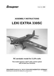
Airspeed Sensor<br />
GRAUPNER G-BOOSTER 160 – Manual 1.91<br />
The JETRONIC-Vx allows the connection of an optional airspeed sensor to the AUXiliary connector.<br />
For the measurement, a pitot tube (Prandtl type) and an electronic pressure sensor are<br />
used. The tube is mounted on the outside of the model in flight direction and the sensor is mounted<br />
inside the model. The two components are connected via the two included pieces of tubing.<br />
The measurement of the airspeed in flight allows several useful functions:<br />
● Determining the (maximum) airspeed [km/h] (see INFO:15 AIRSPEED-PEAK)<br />
● Determining the covered total distance [km] (see INFO:16 AIR-DISTANCE)<br />
● Limiting the airspeed to a value allowed for the aircraft model<br />
(see LIMITS:37 AIRSPEED-MAX)<br />
Connection<br />
In order to achieve a precise airspeed measurement, the pitot tube should measure the stagnation<br />
pressure only on parts that are parallel to the incoming airflow.<br />
● Do not mount the tube on conical areas.<br />
● Keep a minimum distance of 2.5 cm (1") to a parallel surface.<br />
For a more precise measurement, you can also mount two airspeed sensors, for example on the<br />
wing tips, which are connected in parallel using a V-cable.<br />
30
Notes<br />
GRAUPNER G-BOOSTER 160 – Manual 1.91<br />
31