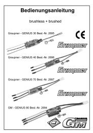
Operating instructions - Graupner
Operating instructions - Graupner
Operating instructions - Graupner

Create successful ePaper yourself
Turn your PDF publications into a flip-book with our unique Google optimized e-Paper software.
PIEZO NT-312 G gyro system<br />
Order No. 5951<br />
<strong>Operating</strong> <strong>instructions</strong><br />
For your own safety<br />
please read the following notes carefully:<br />
WARNING: handling this gyro incorrectly may result in serious personal injury or<br />
damage to property!<br />
On no account short-circuit the connector contacts with any metallic object. You run<br />
the risk of fire and explosion, not to mention damage to the gyro.<br />
On no account dismantle or modify the unit in any way, otherwise you run the risk of<br />
fire or damage to the unit.<br />
On no account use the system in conjunction with any equipment other than the<br />
stated servos and other radio control system components, or you run the risk of fire,<br />
injury and system failure.<br />
Be certain to check the direction of operation of the gyro system. If you set the gyro to<br />
counteract fluctuations in the wrong direction, the model will almost certainly be<br />
uncontrollable in the air.<br />
On no account use the system for any purpose other than for model aircraft - fixedwing<br />
and helicopters - as employed for hobby purposes, otherwise you run the risk of<br />
malfunction and system failure.<br />
Be certain to ensure that the airborne power sources (batteries) are adequately<br />
charged before flying; if a battery becomes flat in flight, you will inevitably lose control<br />
of the model.<br />
On no account operate the system in weather conditions in which the gyro could<br />
become damp or wet, otherwise you run the risk of malfunction or system failure.<br />
Be certain to check that the surface in the model to which the gyro system is attached<br />
is dry, completely clean and free of grease. Fix the unit in place carefully using the<br />
double-sided foam tape supplied, and check from time to time that it is still secure.<br />
If the gyro system comes loose, you will lose control of the model!<br />
Be certain to mount the gyro system in the location recommended by the helicopter<br />
manufacturer, or in a location where vibration is at a minimum. Powerful vibration can<br />
easily reduce the gyro’s performance, and may even lead to system malfunction or<br />
failure.<br />
On no account subject the gyro system to extremely high or low temperatures, water,<br />
severe vibration or high humidity, otherwise you run the risk of malfunction, damage,<br />
reduced performance and system failure.<br />
GRAUPNER GmbH & Co. KG D-73230 KIRCHHEIM/TECK GERMANY<br />
Modifications reserved; errors and printing errors excepted ID# 52634 11/04
PIEZO NT-312 G gyro system<br />
Order No. 5951<br />
General summary<br />
The PIEZO NT-312 G gyro system is mounted in the model in a particular orientation in order to<br />
stabilise the model’s movements around one of the three primary axes.<br />
The gyro system is generally used in model helicopters, where it is looped in between the<br />
receiver and the tail rotor servo in order to control the model’s movements around the vertical<br />
(yaw) axis. Its purpose is to counteract unwanted movements caused by outside influences,<br />
variations in main rotor torque and gusts of wind, and it also provides a speed of rotation around<br />
the vertical axis proportional to the stick movement.<br />
If used in a fixed-wing model aircraft, the gyro system can stabilise any individual axis in the<br />
same way, i.e. the longitudinal axis (roll - ailerons), the lateral axis (pitch - elevator) or the<br />
vertical axis (yaw - rudder).<br />
It is also possible to stabilise the other two major axes in a model helicopter, in addition to the<br />
yaw axis, by installing additional gyro systems. Please refer to the diagrams below which<br />
indicate the correct orientation for the gyro system in the model.<br />
2
PIEZO NT-312 G gyro system<br />
Order No. 5951<br />
Gyro characteristics<br />
All gyro systems compensate for unforeseen outside influences, but this gyro goes one step<br />
further: when the pilot gives a tail rotor command, the gyro maintains a constant rotational<br />
speed which is directly proportional to the position of the stick. If the pilot moves the tail rotor<br />
stick in order to yaw the helicopter, the gyro system automatically monitors the machine’s<br />
rotational speed for any fluctuations, and increases or decreases the tail rotor servo movement<br />
in order to maintain the rotational speed at a constant rate.<br />
A rotary adjustor is located on the case of the PIEZO NT-312 G; this is used to adjust the<br />
maximum effectiveness (gain) of the gyro; a separate channel (gain control) is used to match<br />
the gyro gain, the model, and your personal preferences.<br />
Connecting the gyro to the receiving system<br />
The PIEZO NT-312 G gyro system features two connecting leads which are permanently<br />
attached to the case: the three wire cord should be connected to the tail rotor servo output<br />
socket on the receiver, the one wire cord connects to the gain control channel. Locate the<br />
connector attached to the tail rotor servo lead and plug it into the socket on the gyro unit. Note<br />
that the signal wire (<strong>Graupner</strong>/JR servos: orange) must be at the bottom.<br />
The system in use<br />
Installing the gyro system<br />
Install the sensor unit in the appropriate orientation relative to the axis of the model which you<br />
wish to stabilise, as shown in the sketch. It is important to minimise vibration transfer to the<br />
gyro. Ensure that the case is exactly perpendicular to the desired axis in the model. We<br />
recommend that you mount it using the double-sided foam tape supplied. Press the tape firmly<br />
onto the rear or bottom face of the gyro case, then press it onto the intended surface in the<br />
model. The mounting surface must be clean and grease-free.<br />
Using the gyro system in a helicopter<br />
1. The first step is to complete all the electrical connections between the gyro and the receiving<br />
system. The second is to set the servo travel for the tail rotor to 100% on both sides of<br />
neutral. This is done at the transmitter.<br />
2. Set the servo travel centre offset to zero.<br />
3. Set the tail rotor trim lever to centre; if you have an mc-24 erase the tail rotor trim memory.<br />
4. Temporarily switch off the static torque compensation mixer to ensure that the servo is at<br />
true centre. If your transmitter features a dynamic torque compensation mixer, it must be<br />
3
PIEZO NT-312 G gyro system<br />
Order No. 5951<br />
disabled (switched off) permanently.<br />
5. Be sure to disable the mixer which suppresses the effect of the gyro system in response to<br />
a tail rotor control command (“gyro control”, “gyro suppression”).<br />
6. Switch on the transmitter first, then the receiving system. The LED starts flashing to indicate<br />
that the gyro system is carrying out its self-calibration procedure. Don’t disturb the model<br />
until the LED is glowing constantly.<br />
7. Operate the tail rotor stick on the transmitter and check that the tail rotor responds in the<br />
correct direction.<br />
8. Check that the tail rotor servo output arm is exactly at right-angles (90°) to the tail rotor<br />
control pushrod. You may have to unscrew the servo output arm, rotate it on the splines and<br />
secure it again.<br />
9. The next step is to check the direction in which the gyro system’s corrective action occurs.<br />
This is done by rotating the helicopter slightly around its vertical axis, and observing the<br />
response of the tail rotor servo produced by the gyro. The tail rotor travel must be in the<br />
direction which counteracts the model’s rotation. If the direction of the gyro’s corrective<br />
action is incorrect, reverse it by inverting the gyro system (turn it upside-down).<br />
10. Set your preferred tail rotor control characteristics (Dual Rates, Exponential).<br />
Starting point for the set up:<br />
Normal DR 60% EXP 40% Hover<br />
Aerobatics 1 DR100% EXP 60% 540° stall turn<br />
Aerobatics 2 DR 60% EXP 60% Rolls, other manoeuvres<br />
Note: if you find the tail rotor control uncomfortably powerful, you can "soften" its response to<br />
any extent you like by increasing the exponential value.<br />
In-flight adjustments<br />
Adjusting gyro gain<br />
The regulatory speed of the PIEZO NT-312 G gyro system is so high - even when gyro gain is<br />
set to a high level - that in normal circumstances the model never reaches the onset of<br />
oscillation (tail swinging to and fro), although this does vary according to the model and the tail<br />
rotor servo you are using. For this reason you will need to adjust gyro gain primarily to match<br />
the different rotational speeds used in the flight phases: low rotor speeds for hovering require a<br />
higher gyro gain setting; at higher speeds for aerobatic flying gyro gain should be reduced to<br />
avoid the tail swinging.<br />
Specification – PIEZO NT-312 G gyro system<br />
Power supply: 4,8...6 V (receiver power supply)<br />
Current drain: 10 mA<br />
Dimensions / weight: 19,5 x 11,3 x 20,0 mm, 7 g<br />
<strong>Operating</strong> temperature range: -5°C...+60°C<br />
4