Download - Graupner
Download - Graupner
Download - Graupner

You also want an ePaper? Increase the reach of your titles
YUMPU automatically turns print PDFs into web optimized ePapers that Google loves.
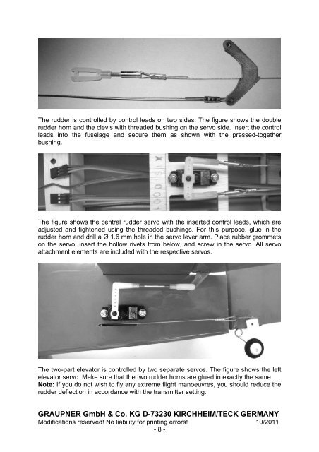
The rudder is controlled by control leads on two sides. The figure shows the double<br />
rudder horn and the clevis with threaded bushing on the servo side. Insert the control<br />
leads into the fuselage and secure them as shown with the pressed-together<br />
bushing.<br />
The figure shows the central rudder servo with the inserted control leads, which are<br />
adjusted and tightened using the threaded bushings. For this purpose, glue in the<br />
rudder horn and drill a Ø 1.6 mm hole in the servo lever arm. Place rubber grommets<br />
on the servo, insert the hollow rivets from below, and screw in the servo. All servo<br />
attachment elements are included with the respective servos.<br />
The two-part elevator is controlled by two separate servos. The figure shows the left<br />
elevator servo. Make sure that the two rudder horns are glued in exactly the same.<br />
Note: If you do not wish to fly any extreme flight manoeuvres, you should reduce the<br />
rudder deflection in accordance with the transmitter setting.<br />
GRAUPNER GmbH & Co. KG D-73230 KIRCHHEIM/TECK GERMANY<br />
Modifications reserved! No liability for printing errors! 10/2011<br />
- 8 -