design and characteristics of a split hopkinson pressure bar apparatus
design and characteristics of a split hopkinson pressure bar apparatus
design and characteristics of a split hopkinson pressure bar apparatus

Create successful ePaper yourself
Turn your PDF publications into a flip-book with our unique Google optimized e-Paper software.
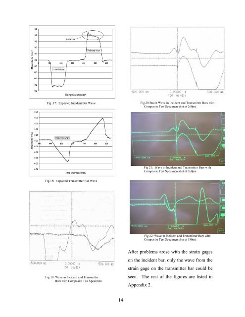
Fig .17: Expected Incident Bar Wave<br />
Fig.18: Expected Transmitter Bar Wave<br />
Fig 19: Wave in Incident <strong>and</strong> Transmitter<br />
Bars with Composite Test Specimen<br />
14<br />
Fig.20 Strain Wave in Incident <strong>and</strong> Transmitter Bars with<br />
Composite Test Specimen shot at 260psi<br />
Fig 21: Wave in Incident <strong>and</strong> Transmitter Bars with<br />
Composite Test Specimen shot at 260psi<br />
Fig 22: Wave in Incident <strong>and</strong> Transmitter Bars with<br />
Composite Test Specimen shot at 180psi<br />
After problems arose with the strain gages<br />
on the incident <strong>bar</strong>, only the wave from the<br />
strain gage on the transmitter <strong>bar</strong> could be<br />
seen. The rest <strong>of</strong> the figures are listed in<br />
Appendix 2.