

WSJT-X_Users_Guide
WSJT-X_Users_Guide
WSJT-X_Users_Guide

Create successful ePaper yourself
Turn your PDF publications into a flip-book with our unique Google optimized e-Paper software.
<strong>WSJT</strong>-X User’s <strong>Guide</strong><br />
April 9, 2013<br />
<strong>WSJT</strong>-X is an experimental version of <strong>WSJT</strong> implementing JT9, a new mode designed<br />
especially for use on the MF and LF bands. JT9 shares many characteristics with the<br />
popular modes JT65 and JT4. All three are designed for making QSOs under extreme<br />
weak-signal conditions. They use nearly identical message structure and source<br />
encoding. JT65 is used for EME on the VHF/UHF bands, and for worldwide QRP<br />
communication at HF. JT4 is used mainly on the microwave bands. In contrast, JT9 is<br />
optimized for the 1.8 MHz, 472 kHz, and 137 kHz bands. It has been found to be useful<br />
also at HF, and even for EME at VHF, while using less than 10% of the bandwidth of<br />
JT65.<br />
JT9 offers five choices for the duration of timed T/R sequences: submodes JT9-1, JT9-<br />
2, JT9-5, JT9-10, and JT9-30 use 1, 2, 5, 10, and 30 minutes, respectively. Sub-modes<br />
with longer transmissions trade reduced throughput for smaller bandwidth and<br />
increased sensitivity. The slowest sub-mode, JT9-30, has total bandwidth 0.4 Hz and<br />
operates at signal-to-noise ratios as low as -40 dB measured in the standard 2.5 kHz<br />
reference bandwidth. JT9-1 is the recommended submode unless you really need the<br />
additional sensitivity of a slower mode.<br />
This document assumes that you are already familiar with <strong>WSJT</strong>. If not, please read<br />
the <strong>WSJT</strong> User’s <strong>Guide</strong> first. It is available online at<br />
http://physics.princeton.edu/pulsar/K1JT/<strong>WSJT</strong>_User_600.pdf.<br />
Installation and Setup<br />
1. <strong>WSJT</strong>-X can be downloaded from the <strong>WSJT</strong> Home Page at<br />
http://www.physics.princeton.edu/pulsar/K1JT/. Click on the <strong>WSJT</strong> link at the left<br />
margin and then on the appropriate download link for <strong>WSJT</strong>-X.<br />
2. Under Windows, execute the downloaded file and follow the installation<br />
instructions. Install <strong>WSJT</strong>-X into its own directory (the suggested default is<br />
C:\<strong>WSJT</strong>X) rather than the conventional C:\Program Files\<strong>WSJT</strong>X.<br />
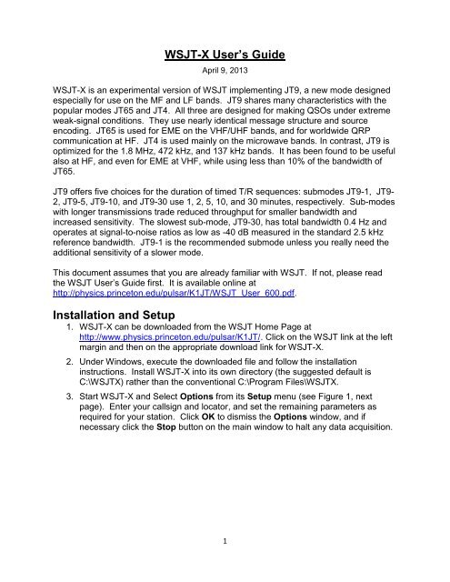
3. Start <strong>WSJT</strong>-X and Select Options from its Setup menu (see Figure 1, next<br />
page). Enter your callsign and locator, and set the remaining parameters as<br />
required for your station. Click OK to dismiss the Options window, and if<br />
necessary click the Stop button on the main window to halt any data acquisition.<br />
1
Fig. 1 — Station tab on the Setup screen.<br />
4. Select submode JT9-1 from the Mode menu and Normal from the Decode<br />
menu. On the Wide Graph window select JT9 Sync (rather than Current or<br />
Cumulative) for data display. Select tab 2 (just below the Erase button) to<br />
choose the alternative set of controls for generating and selecting messages to<br />
be transmitted. Then select File | Open, navigate to directory …\Save\Samples<br />
under your <strong>WSJT</strong>-X installation directory, and open the example file<br />
130228_2158.wav. You should see something like the screen shots in Figure 2,<br />
next page. Note that two JT9 signals have been decoded: KF7JGF is calling CQ,<br />
and G4HSK is responding to a CQ from K1JT. These signals are visible on the<br />
waterfall near audio frequencies 1140 and 1238 Hz, respectively. At SNR = -25<br />
dB, the signal from G4HSK is close to the minimum for reliable decoding. The<br />
strong, wide signal between about 1400 and 1800 Hz is some other data mode;<br />
the JT9 decoder will spend some time trying to make sense of it, and then will<br />
eventually ignore it. The KF7JGF signal is highlighted in green because he is<br />
calling CQ. The signal from G4HSK is highlighted in red because it is directed to<br />
“MyCall”, in this case K1JT.<br />
2
Fig. 2 — Wide Graph (upper) and Main window (lower) after opening the test file<br />
130228_2158.wav.<br />
5. Notice on the waterfall frequency scale that the narrow-band Rx frequency is<br />
marked in green and the Tx frequency in red. The wideband decoding range is<br />
marked by blue arrows. The normal wideband range is 1000 – 2000 Hz, but you<br />
can move the limits using the fMin and fMax spinner controls.<br />
3
6. To get some feeling for controls you will use frequently when making QSOs, try<br />
clicking with the mouse on the decoded text lines and on the waterfall spectrum<br />
display. You should be able to confirm the following behavior:<br />
a. Double-click on decode line highlighted in green — copy callsign and<br />
locator of station calling CQ to “DX Call” and “DX grid”; generate suitable<br />
messages for minimal QSO with this station; moce Rx (green) and Tx<br />
(red) frequency markers on waterfall scale to match frequency of station<br />
calling CQ.<br />
b. Double-click on decode line highlighted in red — similar to (a) except Tx<br />
frequency is not moved.<br />
c. Click on waterfall — move Rx frequency (green marker) to selected<br />
frequency.<br />
d. CTRL-click on waterfall — move Rx and Tx frequencies.<br />
e. Double-click on waterfall — move Rx frequency and decode there. Notice<br />
that the decoded text now appears in the “QSO” window.<br />
f. CTRL-double-click — move Rx and Tx frequencies and decode there.<br />
7. Examine the user options presented on the Setup menu. You may want to<br />
select some of these for your normal operation.<br />
8. Click the Monitor button to return to normal receive operation and set the<br />
background noise level to around 30 dB on the thermometer scale at lower left of<br />
the main screen. With the slider at mid-scale, the dB scale is calibrated relative<br />
to the least significant bit of a 16-bit A/D converter in the soundcard. This setting<br />
is not critical.<br />
9. You should now be ready to make QSOs with the JT9 modes in <strong>WSJT</strong>-X.<br />
4
Hints for New <strong>Users</strong><br />
1. AGC off (or turn RF gain down until AGC action is minimal).<br />
2. Set background noise level to about 30 dB on the <strong>WSJT</strong>-X meter. For best<br />
dynamic range, the slider to the right of the green-bar indicator should be near<br />
mid-scale when this is true.<br />
3. The waterfall frequency range always starts at 1000 Hz, which means that your<br />
on-the-air frequency range starts exactly 1 kHz above your dial frequency. The<br />
upper frequency limit depends on JT9 sub-mode, the setting of FFT bins/pixel,<br />
and the width of the waterfall graph. In normal use the recommended audio<br />
frequency range is 1000–2000 Hz for sub-modes JT9-1 and JT9-2, 1000–1300<br />
Hz for JT9-5, 1000–1150 Hz for JT9-10, and 1000–1050 Hz for JT9-30.<br />
4. For best waterfall sensitivity, set N Avg ≥ 3.<br />
5. Double-click on a decoded message to copy the callsign and locator into DX Call<br />
and DX Grid. This will also generate appropriate standard messages, including<br />
signal report.<br />
6. You have three options for the 2D plot under the waterfall. Check Current to see<br />
the spectrum averaged over the most recent N Avg FFTs. Check Cumulative to<br />
see the spectrum averaged since start of the Rx interval. Check JT9 Sync to<br />
see the program’s first attempt at identifying a valid JT9 sync signal in the<br />
selected submode.<br />
7. <strong>WSJT</strong>-X requires that computer time information at transmitter and receiver<br />
should be accurate to within about ± 2 seconds. The recommended software for<br />
synchronization by internet is Meinberg NTP. See<br />
http://www.satsignal.eu/ntp/setup.html for installation instructions.<br />
Bug Reports and Feature Requests<br />
<strong>WSJT</strong>-X is still in an early stage of development, and user feedback is welcome. Send<br />
reports to k1jt@arrl.net.<br />
5
The JT9 Protocol<br />
JT9 is a mode designed for making QSOs at MF and LF. The mode uses essentially<br />
the same 72-bit structured messages as JT65. Error control coding (ECC) uses a<br />
strong convolutional code with constraint length K=32, rate r=1/2, and a zero tail,<br />
leading to an encoded message length of (72+31) × 2 = 206 information-carrying bits.<br />
Modulation is 9-FSK: 8 tones are used for data, one for synchronization. Sixteen<br />
symbol intervals are used for synchronization, so a transmission requires a total of 206<br />
/ 3 + 16 = 85 (rounded up) channel symbols. Symbol durations are approximately<br />
(TRperiod - 8) / 85, where TRperiod is the T/R sequence length in seconds. Exact<br />
symbol lengths are chosen so that nsps, the number of samples per symbol (at 12000<br />
samples per second) is a number with no prime factor greater than 7. This choice<br />
makes for efficient FFTs. Tone spacing of the 9-FSK modulation is df = 1 / tsym =<br />
12000 / nsps, equal to the keying rate. The total occupied bandwidth is 9 × df. The<br />
generated signal has continuous phase and constant amplitude, and there are no key<br />
clicks.<br />
Parameters of five JT9 sub-modes are summarized in the following table, along with<br />
approximate S/N thresholds measured by simulation on an AWGN channel. Numbers<br />
following “JT9-” in the sub-mode names specify TRperiod in minutes.<br />
Submode nsps Symbol<br />
Duration<br />
(s)<br />
Tone<br />
Spacing<br />
(Hz)<br />
Signal<br />
Bandwidth<br />
6<br />
(Hz)<br />
S/N<br />
Threshold *<br />
(dB)<br />
QSO<br />
Time<br />
(minutes)<br />
JT9-1 6912 0.58 1.736 15.6 -27 6<br />
JT9-2 15360 1.28 0.781 7.0 -30 12<br />
JT9-5 40960 3.41 0.293 2.6 -34 30<br />
JT9-10 82944 6.91 0.145 1.3 -37 60<br />
JT9-30 252000 21.00 0.048 0.4 -42 180<br />
* Noise power measured in 2500 Hz bandwidth.