
Create successful ePaper yourself
Turn your PDF publications into a flip-book with our unique Google optimized e-Paper software.
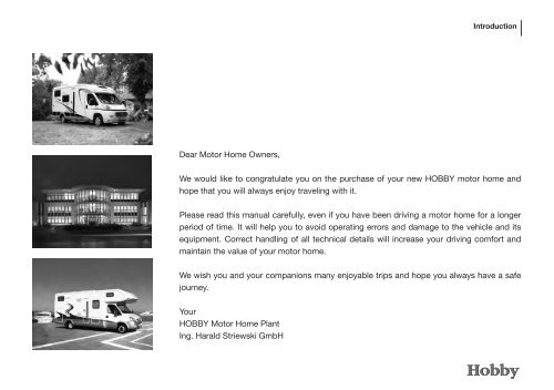
Dear Motor Home Owners,<br />
Introduction<br />
We would like to congratulate you on the purchase of your new HOBBY motor home and<br />
hope that you will always enjoy traveling with it.<br />
Please read this manual carefully, even if you have been driving a motor home for a longer<br />
period of time. It will help you to avoid operating errors and damage to the vehicle and its<br />
equipment. Correct handling of all technical details will increase your driving comfort and<br />
maintain the value of your motor home.<br />
We wish you and your companions many enjoyable trips and hope you always have a safe<br />
journey.<br />
Your<br />
HOBBY Motor Home Plant<br />
Ing. Harald Striewski GmbH
00-1<br />
Introduction<br />
<strong>Chapter</strong> 1: Introduction<br />
1.1 General information ................................................ 01-1<br />
1.2 Before taking your .rst drive .................................. 01-1<br />
1.3 Designations in the operating instructions ............. 01-2<br />
<strong>Chapter</strong> 2: Safety<br />
2.1 General information ................................................ 02-1<br />
2.2 Fire protection ........................................................ 02-1<br />
2.3 Road safety ............................................................ 02-2<br />
2.4 What to observe before taking your first drive ....... 02-2<br />
2.5 Before and while driving......................................... 02-3<br />
2.6 Notes for your journey ........................................... 02-5<br />
2.7 Vehicle tool kit ........................................................ 02-8<br />
2.8 Emergency equipment ........................................... 02-9<br />
2.9 When you stop driving ......................................... 02-10<br />
<strong>Chapter</strong> 3: Chassis<br />
3.1 Chassis .................................................................. 03-1<br />
3.2 Loading .................................................................. 03-1<br />
3.3 Leveling supports ................................................... 03-4<br />
3.4 Entrance step ......................................................... 03-5<br />
3.5 Vehicle identification number (VIN) ........................ 03-6<br />
3.6 Additional pneumatic springs ................................ 03-6<br />
3.7 Towing fixture ......................................................... 03-7<br />
3.8 Externally mounted fixtures ................................... 03-8<br />
3.9 Automatic transmission ......................................... 03-8<br />
<strong>Chapter</strong> 4: Wheels, tyres, brakes<br />
4.1 Wheels ................................................................... 04-1<br />
4.2 Tyres ....................................................................... 04-1<br />
4.3 Tyre pressure .......................................................... 04-2<br />
4.4 Tread depth ............................................................ 04-2<br />
4.5 Wheel rims ............................................................. 04-3<br />
4.6 Spare tire ................................................................ 04-3<br />
4.7 Tyre repair kit .......................................................... 04-4<br />
4.8 Brakes .................................................................... 04-8<br />
<strong>Chapter</strong> 5: Exterior Structure<br />
5.1 Overview of tank and service flaps ........................ 05-1<br />
5.2 Ventilation ............................................................... 05-5<br />
5.3 Opening and closing doors and flaps .................... 05-7<br />
5.4 Roof rail ................................................................ 05-12<br />
5.5 Bicycle carrier ...................................................... 05-13<br />
5.6 Load carrier .......................................................... 05-14<br />
5.7 Sun awning .......................................................... 05-15<br />
<strong>Chapter</strong> 6: Interior Structure<br />
6.1 Opening closing doors and flaps ........................... 06-1<br />
6.2 Mount for flat screen TV ......................................... 06-5<br />
6.3 Tables ..................................................................... 06-5<br />
6.4 Bed conversion ...................................................... 06-8<br />
6.5 Cushion arrangements ........................................... 06-9<br />
6.6 Elevated berths .................................................... 06-15
6.7 Windows .............................................................. 06-16<br />
6.8 Dimming system for driver's cabin ...................... 06-18<br />
6.9 Skylight ................................................................ 06-19<br />
6.10 Pivoting seats in the driver's cab ......................... 06-21<br />
6.11 Construction of the seats ..................................... 06-22<br />
6.12 Seatbelts in the caravan....................................... 06-24<br />
6.13 Overview of the seating arrangements ................ 06-25<br />
6.14 Overview of day and night positions .................... 06-29<br />
<strong>Chapter</strong> 7: Electrical Installations<br />
7.1 Safety instructions ................................................. 07-1<br />
7.2 Elements of the electrical system .......................... 07-1<br />
7.3 Electric power supply ............................................. 07-9<br />
7.4 Functioning of the electrical supply unit .............. 07-10<br />
7.5 <strong>Caravan</strong> battery .................................................... 07-13<br />
7.6 Fuse protection for the electric system................ 07-14<br />
7.7 Mobile navigation ................................................. 07-15<br />
7.8 Subsequently installed devices ............................ 07-16<br />
<strong>Chapter</strong> 8: Water<br />
8.1 Water supply .......................................................... 08-1<br />
8.2 Hot water supply ................................................... 08-4<br />
8.3 Flushing toilet ......................................................... 08-5<br />
<strong>Chapter</strong> 9: Gas<br />
9.1 General safety rules when using LPG fittings ........ 09-1<br />
Introduction<br />
9.2 Gas supply ............................................................. 09-3<br />
9.3 Hot-air heating ....................................................... 09-5<br />
9.4 Hot-water heating ................................................ 09-10<br />
9.5 Refrigerator .......................................................... 09-14<br />
9.6 Gas cooker ........................................................... 09-16<br />
9.7 Oven ..................................................................... 09-18<br />
<strong>Chapter</strong> 10: Maintenance and Care<br />
10.1 Maintenance .......................................................... 10-1<br />
10.2 Airing ...................................................................... 10-1<br />
10.3 Care ........................................................................ 10-2<br />
10.4 Winter operation ..................................................... 10-5<br />
<strong>Chapter</strong> 11: Sanitation and Environmental Protection<br />
11.1 The environment and traveling ............................... 11-1<br />
11.2 Returning the vehicle ............................................. 11-4<br />
<strong>Chapter</strong> 12: Technical Data<br />
12.1 Weights according to 92/21/EWG ......................... 12-1<br />
12.2 Inflation pressures ................................................. 12-2<br />
12.3 Technical data........................................................ 12-3<br />
12.4 Tires and rims for basic mobile homes ................. 12-7<br />
12.5 Accessory weights ................................................ 12-9<br />
Index ................................................................................ Ix-1<br />
Appendix ............................................................................A-1<br />
00-2
01-1<br />
Introduction<br />
<strong>Chapter</strong> 1: Introduction<br />
Our motor homes are continuously being further developed<br />
and for this reason we must reserve the right to make<br />
changes to the equipment, shape and technology. Certain<br />
kinds of accessories are also described in this user manual<br />
that are not part of the standard scope of delivery. For this<br />
reason, no claims may be asserted against HOBBY based<br />
on the contents of this user manual. Those accessories that<br />
are available at the time of going to print are described here.<br />
They have been applied on a par for all floor plans. Please<br />
note that it was not possible to describe all of the individual<br />
variations here. If you have any special questions concerning<br />
accessories or the technology of the vehicle, your dealer will<br />
be happy to answer them.<br />
1.1 General information<br />
Your HOBBY motor home has been built in accordance<br />
with the latest technology and approved safety regulations.<br />
Despite all precautionary measures, however, it is possible<br />
that passengers may be hurt or the motor home damaged if<br />
the safety instructions in this user manual and the warning<br />
stickers placed throughout the motor home are not observed.<br />
Please use the motor home only when it is technically in top<br />
condition.Any defects that affect the safety of passengers or<br />
the motor home should be remedied immediately by trained<br />
personnel.<br />
The brake system and the gas system should only be checked<br />
and repaired by an authorised workshop.<br />
Please ensure that all of the deadlines for checking equipment<br />
and inspections are met.<br />
1.2 Before taking your .rst drive<br />
Please do not consider this manual to be just a means of reference,<br />
but familiarize yourself thoroughly with it before taking<br />
your first drive.<br />
Fill out the guarantee cards in the different manuals for the installed<br />
equipment and fittings and send them to the manufacturers.<br />
This will ensure guarantee claims for any of the equipment.<br />
In accordance with guarantee conditions, HOBBY's dealer<br />
will give you a 5-year guarantee on the consistency of the<br />
motor home. Your dealer will give you a guarantee booklet,<br />
“5 Years‘ Guarantee on Consistency“ when you pick up<br />
your vehicle.<br />
Note: If a consistency test has not been carried out, you will<br />
forfeit any claims for a 5-year guarantee on consistency.
Please note the following before operating the vehicle:<br />
• Check the tyre pressure.<br />
Please refer to the section on tyre pressure<br />
• Load the vehicle correctly. Keep to the technically permis-<br />
sible overall mass.<br />
Please refer to the section on loading.<br />
• Charge up the batteries fully before each journey<br />
Please refer to the section on the starter battery.<br />
• If the temperature outside is below 0° C, heat the vehicle<br />
before filling up the water system.<br />
Please refer to the section on water supply/filling the fresh<br />
water tank.<br />
• Tighten the wheel nuts after having driven the first 50 km.<br />
• Switch off all fitted devices that operate on gas before<br />
filling the petrol tank.<br />
• Tightly strap gas bottles in the gas bottle box during trans-<br />
portation.<br />
• When camping in winter, heat the vehicle at night if there is<br />
danger of frost.<br />
Please refer to the section on operating in winter/heating.<br />
• Keep compulsory ventilation clear.<br />
Please refer to the section on windows/roof fan/airing.<br />
• When the vehicle is not in use, empty the entire water<br />
system and leave the water faucets open in a neutral<br />
position. This prevents the water system from being<br />
damaged by frost.<br />
Please refer to the section on emptying the water system.<br />
Introduction 01-2<br />
1.3 Designations in the operating instructions<br />
This manual explains the motor home in the following<br />
manner:<br />
Texts and illustrations<br />
Texts that refer to illustrations are found directly below the<br />
illustrations.<br />
Details in illustrations (here: entrance) have been given item<br />
numbers j .<br />
Lists<br />
Lists are given in the form of key words and shown as bullet<br />
points using “-“.<br />
1
01-3<br />
Introduction<br />
Handling instructions<br />
Handling instructions are also given in the form of key words<br />
beginning with the symbol “•“.<br />
Notes<br />
Warnings<br />
Notes point out important details that ensure your motor<br />
home and its fittings will function perfectly. Please remember<br />
that there may be some differences in description to the<br />
various kinds of equipment that can be supplied.<br />
Warnings make you aware of dangers that may lead to<br />
material being damaged or even people being hurt if they<br />
are not observed.<br />
Environmental Tips<br />
Environmental tips give you possibilities for lessening the<br />
impact on the environment.
Introduction
02-1<br />
Safety<br />
<strong>Chapter</strong> 2: Safety<br />
2.1 General information<br />
• Ensure that there is sufficient ventilation. Never cover builtin<br />
compulsory ventilation (skylights with compulsory ventilation<br />
or roof fan). Keep compulsory ventilation free of snow<br />
and leaves - danger of suffocation!<br />
• Operating and user instructions for built-in equipment (refrigerator,<br />
heating, cooker, etc.) as well as for the basic vehicle<br />
must be observed at all times.<br />
• If accessories or optional equipment is to be installed, this<br />
may change the measurements, weight and road performance<br />
of the engine home. Some accessories must be registred<br />
and entered in the vehicle's papers.<br />
• Use only tyres and rims that have been approved for your<br />
engine home. Please refer to the vehicle's registration papers<br />
for information on tyre and rim sizes.<br />
2.2 Fire protection<br />
Precautions against .r e<br />
• Never leave children alone in the vehicle.<br />
• Keep in.ammable materials away from all heating and cooking<br />
devices.<br />
• Any changes to the electric system, accelerator system or<br />
built-in devices may only be carried out by an authorised<br />
workshop.<br />
• Install a fire extinguisher next to the main entrance.<br />
• Store a fire blanket near the cooker.<br />
• Do not block any escape routes.<br />
• Familiarise yourself with all safety measures set up on the<br />
property.<br />
Fighting fire<br />
• Immediately evacuate all passengers.<br />
• Close the main stop valve on the accelerator cylinder and<br />
the accelerator stop valves for the consumer loads.<br />
• Turn off the electric supply.<br />
• Sound the alarm and call the fire department.<br />
• Only fight the fire yourself if you can do so without risk.
2.3 Road safety<br />
• Before driving, check that the signal and light equipment,<br />
steering and brakes all function properly.<br />
• If the vehicle has been standing for a longer period of time<br />
(approx. 10 months) have an authorised workshop check<br />
the brake system and the accelerator system.<br />
• Completely open and fasten the dimming system on the<br />
front and side windows.<br />
• While moving all passengers must be secured with seat<br />
belts and may not move around in the vehicle.<br />
• In winter, the roof must be cleared of snow and ice before<br />
driving.<br />
• Regularly check the tyre pressure before driving. False tyre<br />
pressure can cause excessive wear, damage to the tyres or<br />
even lead to a burst tyre.<br />
• Child seats may only be mounted on seats that have a<br />
three-point seat belt installed by the factory.<br />
• Turn the reversible seats in the direction of travel and lock<br />
them. The seats may not be turned while driving.<br />
2.4 What to observe before taking your first<br />
drive<br />
Safety 02-2<br />
Vehicle registration<br />
Every vehicle that drives on public roads must be registered. This<br />
also applies to your new engine home. Apply for registration at<br />
your local Driver and Vehicle Licensing Agency.<br />
You must show the following when applying for<br />
registration:<br />
- registration document, Part II<br />
- insurance coverage<br />
- proof of personal identity or confirmation of registration by a<br />
local authority<br />
- if applicable, power of attorney to register the vehicle<br />
- If applicable, the direct debit authorisation for motor vehicle<br />
tax<br />
General inspection<br />
In common with passenger cars new engine homes with a permissible<br />
total weight up to 3.5 tonnes do not have to undergo<br />
a general inspection for the first three years after initial registration.<br />
After this they must undergo a general inspection every<br />
two years. Engine homes weighing between 3.5 and 7.5 tonnes<br />
must undergo a general inspection every two years during the<br />
first six years following initial registration. After this a general<br />
inspection must be carried out every year.
02-3<br />
Safety<br />
The general inspection can be carried out by the German<br />
Technical Surveyance Association (TÜV), the German Engine<br />
Vehicle Surveyance Association (DEKRA) or an officially<br />
approved expert.<br />
Any changes made to the vehicle that underlie German<br />
Road Traffic Licensing Regulations must be officially<br />
authorised!<br />
If you have any further questions or difficulties, your authorised<br />
<strong>Hobby</strong> dealer will always be available to assist you!<br />
2.5 Before and while driving<br />
As the owner / driver of the vehicle, you are responsible for the<br />
state of the vehicle. Please observe the following points:<br />
Preparing the vehicle<br />
Check the exterior of the vehicle and carry out the following<br />
preparations before driving:<br />
Preparing the vehicle<br />
• If the levelling supports have been extended, retract them.<br />
• Close all the windows in the engine home as well as skylights<br />
in the roof.<br />
• Retract the entrance step.
• Close the tap for the waste water tank.<br />
• Close all taps and quick-action stop valves for accelerator<br />
devices. The only exception is for the heating if this should<br />
be used while driving.<br />
• If necessary remove the 230 V electric cable from the exterior<br />
socket.<br />
• If necessary, retract the satellite dish.<br />
• If necessary retract the TV aerial as far as possible or fold<br />
down the satellite dish.<br />
• If necessary secure any loads on the roof ensuring that<br />
they cannot slide.<br />
• If necessary secure bicycles; ensure that they cannot slide<br />
and check that the existing lighting systems are not<br />
covered.<br />
• If necessary turn off the light in the tent in front of the<br />
engine home.<br />
Interior<br />
Some preparations must also be carried out inside the mobile<br />
home.<br />
Preparing the interior<br />
• Sort loose objects and stow them in the compartments.<br />
• Place heavy objects in the lower compartments.<br />
• If necessary switch the refrigerator to 12 V operation.<br />
Safety 02-4<br />
• Ensure that no liquids, including those in the refrigerator,<br />
will leak.<br />
• Secure accelerator cylinders.<br />
• Fold down and secure the table.<br />
• Turn off interior lights.<br />
• Secure the table and, if possible, lower it.<br />
• Close doors (including refrigerator door), drawers and<br />
flaps firmly.<br />
• Heavy and/or voluminous objects (e.g. TV, radio) must be<br />
secured before driving.<br />
• Brace the safety device for the table.<br />
• Completely open and secure the optional cockpit dimming<br />
system.<br />
Do not overload the vehicle! It is imperative that you not the<br />
permissible axle loads, the technically permissible overall<br />
mass as well as the permissible height, width and length<br />
of the mobile home.<br />
Place a not with all important measures and weights in a<br />
visible place in both the caravan and the driver‘s cabin.
02-5<br />
Safety<br />
Driver‘s cabin<br />
Do not forget the following:<br />
• Adjust the interior and exterior mirrors as well as your<br />
seat.<br />
• Check the lights.<br />
In addition:<br />
• Check your tyre pressure.<br />
• Check all liquids, such as oil, cooling water, brake fluid and<br />
windscreen cleaning liquid, and fill them up if necessary.<br />
• Turn off all accelerator devices (heating, refrigerator, etc.)<br />
before putting petrol in the tank.<br />
Before driving off<br />
Before you drive off you should be able to answer the following<br />
questions with “yes“:<br />
• Is there a first-aid kit; a warning triangle and a warning<br />
jacket on board?<br />
• Are all the lights working (headlights, dipped headlights,<br />
brake lights and indicators)?<br />
2.6 Notes for your journey<br />
Your mobile home is not an automobile!<br />
In many situations, it reacts very differently to a “normal“ automobile.<br />
Therefore, you should be prepared for the following<br />
differences:<br />
Loading<br />
The following applies for loading:<br />
• Load evenly. Heavy or bulky objects should be placed in the<br />
lower compartments!<br />
• In the interior, store luggage in cupboards and compartments.<br />
• Secure all doors and flaps.
• After you have finished loading, check the overall weight on<br />
a public scales.<br />
Roof load (50 kg maximum)<br />
The height of the mobile home may vary from one journey to<br />
the next due to different roof loads.<br />
The following applies for roof loads:<br />
• Add the measurement of the roof load to the height of the<br />
mobile home.<br />
• Place a not visibly in the driver's cab giving the overall height.<br />
This saves having to calculate the height when driving under<br />
bridges and through tunnels.<br />
Rear garage<br />
When loading the rear garage adhere to the permissible axle<br />
loads and the technically permissible total mass. Distribute<br />
payload evenly. Excess point loads will damage the floor covering.<br />
• The maximum permissible load for the rear external<br />
storage locker is 200 kg (Fiat) or 350 kg (Iveco).<br />
• On no account should the permissible rear axle load be<br />
exceeded.<br />
• Due to load removal on the front axle, it is considerably<br />
more difficult to handle the vehicle when the rear garage<br />
is fully loaded.<br />
Safety 02-6<br />
Passenger safety<br />
The following applies while driving:<br />
• Only those seats equipped with safety belts may be used<br />
by passengers.<br />
• While driving, passengers may not stay in the alcove or the<br />
beds.<br />
• Passengers must remain in their seats with their seat belt<br />
on!<br />
• Do not open the door latch!<br />
• No extra passengers may remain in the vehicle!<br />
Braking<br />
The following applies for braking:<br />
• Not the longer braking distance, especially on wet roads.<br />
• When driving downhill, select a gear that is not higher than<br />
when driving uphill.<br />
Reversing/Manoeuvring<br />
Your engine home is far larger than a car.<br />
The following applies to reversing/manoeuvring<br />
• Even if the wing mirrors are correctly adjusted there is a<br />
significant blind spot.<br />
• When reversing or parking in places with poor visibility get<br />
help to guide you in.
02-7<br />
Safety<br />
Driving<br />
Take a trial drive before leaving on your first large journey in<br />
order to familiarize yourself with the mobile home. Remember<br />
to practise reversing. The base vehicle is a commercial vehicle;<br />
adjust your driving style accordingly.<br />
The following applies for driving:<br />
• Do not underestimate the length of the engine home. Due<br />
to the relatively long rear overhang larger vehicles can<br />
veer to one side and, in unfavourable conditions, the rear<br />
can hit the ground.<br />
• Be careful when driving into inner courtyards and through<br />
entrance gates.<br />
• The mobile home may start to swing from side to side in<br />
cross-winds, on wet or icy roads.<br />
• Adjust your speed to road and traffic conditions.<br />
• Long descents with a slight gradient can become dangerous.<br />
Adjust your speed from the very beginning to allow you to<br />
speed up if necessary without endangering other automobiles.<br />
• As a general rule, never drive faster downhill than uphill.<br />
• The mobile home may be caught up in a slipstream when<br />
overtaking or being overtaken by lorries with trailers or buses.<br />
This effect is counteracted by lightly counter-steering.<br />
Driving arround corners<br />
Due to its height, a mobile home begins to sway more quickly<br />
than an automobile.<br />
The following applies for driving arround corners:<br />
• Never drive too quickly into a corner!<br />
Driving economically<br />
The engine of your mobile home has not been designed to drive<br />
constantly under a full load.<br />
The following applies when driving:<br />
• Do not keep your foot down on the accelerator!<br />
• The final 20 km/h before reaching top speed require up to<br />
50 % more fuel!<br />
Getting petrol<br />
A number of devices that use an open flame have been built<br />
into your mobile home.<br />
The following applies when getting petrol:<br />
• Turn off all accelerator devices (heating, refrigerator, etc.)!<br />
• Turn off all mobile phones!<br />
• Never get anything other than diesel fuel.<br />
• Never mistakenly fill the fresh water tank with fuel.
7 6<br />
1 2 3 4<br />
2.7 Vehicle tool kit (only if the vehicle is equipped<br />
with levelling supports)<br />
Each vehicle comes with individual basic equipment including<br />
a vehicle tool kit and accessories:<br />
- screwdriver j<br />
- nut wrench k<br />
- nut wrench l (only if the vehicle is equipped with levelling<br />
supports)<br />
- ratchet wrench m<br />
- car jack n<br />
- chocks o<br />
- tool bag p<br />
5<br />
6<br />
2<br />
- tool bag q<br />
- pilot lamp r<br />
- towing eye s<br />
9<br />
8<br />
Safety 02-8<br />
5<br />
10<br />
7
02-9<br />
Safety<br />
2.8 Emergency equipment<br />
To be prepared in case of an emergency, you should always<br />
carry the three emergency devices on board and familiarize<br />
yourself with them.<br />
First-aid kit<br />
The first-aid kit should always be at hand and have a fixed<br />
position in your mobile home. Any objects removed from the<br />
first-aid kit should be replaced immediately. Expiry dates should<br />
be checked regularly.<br />
Reflective jacket (not included in scope of delivery)<br />
In acc. with EN 471, we recommend that you carry and wear<br />
a reflective jacket with white retro-reflective stripes whenever<br />
you leave the vehicle on open roads and emergency strips. The<br />
driver should wear this jacket when the vehicle<br />
• comes to a stop outside city limits on an obscure rural road<br />
because of an accident or breakdown, if the view is poor<br />
due to bad weather, in twilight or darkness, or<br />
• when it must be secured by means of a warning triangle<br />
on the emergency strip of the engineway because of an<br />
accident or breakdown.<br />
100 m<br />
Warning triangle<br />
The warning triangle should also always be at hand and have<br />
a fixed position in your mobile home, preferably together with<br />
the first-aid kit.<br />
In an emergency<br />
• Set up the warning triangle at least 100 m in front of the<br />
danger zone!
2.9 When you stop driving<br />
Selecting a parking space<br />
The following applies for selecting a parking space:<br />
• Select a parking space that is as level as possible.<br />
• If possible, pick your spot in daylight.<br />
Securing the vehicle<br />
The following applies when securing the vehicle:<br />
• Put the vehicle in gear.<br />
• Pull on the handbrake.<br />
• If necessary, extend extra vehicle supports.<br />
• If necessary, use blocks (not in scope of delivery).<br />
If the temperature is below 0°C only put the handbrake<br />
on lightly and ensure that the vehicle is in gear to prevent<br />
the handbrake from freezing up!<br />
When turning the driver‘ seat, ensure that you do not accidently<br />
disengage the handbrake.<br />
Switching electric consumption:<br />
Safety 02-10<br />
The following applies when switching electric consumption:<br />
• Switch the refrigerator from 12 V to accelerator or 230 V.<br />
Otherwise, if the engine is not on, the 12 V electrical supply<br />
will automatically turn itself off after a few minutes.<br />
• Open the main stop valve on the accelerator cylinder and<br />
the accelerator stop valve on the consumer required.<br />
Water system<br />
Empty the entire water system if the vehicle is not heated when<br />
there is danger of frost. Leave the water faucets as well as all<br />
drain valves open to prevent damage from frost.<br />
Water that has been left to stand in the fresh water tank or<br />
water pipes quickly becomes undrinkable. Therefore always<br />
flush the water pipes thoroughly with several litres of fresh<br />
water before using them.
02-11<br />
Safety<br />
Saving energy in winter<br />
It is very easy to save energy inside your mobile home. This<br />
applies especially to heating in winter.<br />
The following applies for saving energy:<br />
• Meter the exact use of ventilation in the vehicle and the<br />
heating valve.<br />
• Install winter mats on the inner sides of the driver‘s cabin<br />
and the windscreen (not included in scope of delivery).<br />
• Attach the insulating mat between the driver‘s cab and the<br />
interior of the mobile home (not included in scope of delivery)<br />
or, for the Sphinx model, completely shut the sliding<br />
door to the driver‘s cab.<br />
• Open the outside door as seldom and briefly as possible.<br />
• If you are camping in winter, attach a small outer tent. This<br />
will offer protection against the cold.
Safety
03-1<br />
Chassis<br />
<strong>Chapter</strong> 3: Chassis<br />
3.1 Chassis<br />
The chassis includes parts of the frame and the axles. No<br />
technical changes may be made, as otherwise the general type<br />
approval will expire!<br />
3.2 Loading<br />
Technical changes may only be carried out after being<br />
released by the manufacturer.<br />
For further information, please refer to the enclosed operating<br />
instructions for the basic vehicle.<br />
The maximum axle loads as well as the technically permissible<br />
overall mass entered in the vehicle‘s documents may<br />
not be exceeded.<br />
Weights of motor homes in accordance with 92/21/EWG<br />
Please refer to the de.nition of masses for motor homes!<br />
De.nition of Masses for Motor homes<br />
Throughout Europe, EU Guideline 92/21/EWG is applicable for<br />
calculating the masses (weights) and resulting loads for motor<br />
homes. The terms and basis used for calculations are<br />
explained below.<br />
1. Technically permissible overall mass<br />
The figure for the technically permissible overall mass is based<br />
on information given by the <strong>Hobby</strong> Motor home Plant in cooperation<br />
with the manufacturer of the base vehicle. This mass<br />
was determined in extensive calculations and tests and, for<br />
safety reasons, it may not be exceeded under any<br />
circumstances.<br />
2. Mass when the vehicle is ready to start<br />
The mass when the vehicle is ready to start corresponds to the<br />
mass of the empty vehicle including lubricants, tools, spare<br />
tyre (and/or repair kit), petrol (100 %), booster battery, all of the<br />
standard equipment mounted by the factory as well as 75 kg<br />
for the driver, plus basic equipment (gas, water, electric).<br />
3. Basic equipment<br />
The basic equipment includes the masses for fresh water and<br />
the gas storage containers, which have been filled to 90 % of<br />
their total capacity. The masses for the individual models are<br />
calculated in detail as follows:
a) liquid gas supply<br />
D 615 AK<br />
(3500 kg)<br />
Toskana<br />
Toskana Exclusive<br />
other<br />
models<br />
No. of 11 kg gas bottles 2 2 2<br />
Sphinx<br />
all<br />
models<br />
Weight of an 11 kg aluminium bottle 5,5 5,5 5,5<br />
Weight of an 11 kg gas filling (90 %) 9,9 9,9 9,9<br />
b) liquids<br />
Total: 31 31 31<br />
200 l fresh water tank (90 %) - - 180<br />
100 l fresh water tank (90 %) - 90 -<br />
10 l fresh water tank (90 %) 9<br />
Total basic equipment: 40 121 211<br />
Chassis 03-2
03-3<br />
Chassis<br />
4. Loading<br />
Loading corresponds to the difference between the "technically<br />
permissible overall mass" and the "mass when the vehicle is ready<br />
to start". This value must take into consideration the masses<br />
for passengers (conventional load: 75 kg x no. of seats, driver<br />
excepted), additional equipment and personal belongings.<br />
Check to ensure that the masses of all objects transported<br />
in the motor home have been taken into consideration, e.g.<br />
passengers, additional equipment, basic equipment and<br />
personal belongings such as clothes, food, pets, bicycles,<br />
surfboards, other sport equipment, etc.).<br />
Under no circumstances may the technically permissible<br />
total load be exceeded when the motor home has been<br />
loaded.<br />
The mass when the vehicle is ready to start includes an additional<br />
value for liquids and gas, etc. (see basic equipment). Part<br />
of this additional value can also be used for additional loads if,<br />
for example, you would like to travel with empty water tanks or<br />
without gas bottles.<br />
5. D 615 AK and D 690, 3500 kg<br />
Before driving, you must open the overflow valve for the<br />
fresh water tank.<br />
To reduce the weight when the vehicle is ready to start, the<br />
fresh water tank has been fitted out with an overflow valve,<br />
located to the right in the seat and marked with a warning<br />
sign. Before you begin driving, open the overflow valve. The<br />
contents of the fresh water tank will run off until, for weight<br />
reasons, only approx. 10 litres are left. When the vehicle is<br />
standing, the valve can be closed, allowing you to use the full<br />
volume of the tank.<br />
A reduced fresh water supply when the vehicle is ready to<br />
start has been entered in the vehicle's registration papers. The<br />
motor home may only be operated on public roads when the<br />
overflow valve is open. The driver is responsible for ensuring<br />
that this requirement is fulfilled as well as for observing the<br />
technically permissible total weight.
3.3 Levelling supports<br />
2<br />
The optional levelling supports are located in the rear area by<br />
the frame extension.<br />
Swinging out the levelling supports<br />
• To release the levelling supports, press the lever j and<br />
pull it backwards.<br />
• Swivel the levelling supports down.<br />
• If necessary, secure the foot k to prevent it from sinking<br />
into the ground and place it on a firm base.<br />
• Place the crank on the hexagon head l and carefully<br />
tighten the levelling support.<br />
• Use the crank to level the levelling supports until the vehicle<br />
stands level.<br />
3<br />
Chassis 03-4<br />
Retracting levelling supports<br />
• Use crank to release levelling supports.<br />
• Press the level j and push the lower part of the levelling<br />
support upwards.<br />
• Swivel the levelling support upwards until it is level.<br />
• Press the level j and push the levelling supports apart until<br />
they are secure to prevent their falling down.<br />
- Do not use the levelling supports as a car jack. Their<br />
sole purpose is to stabilise the motor home when it is<br />
parked.<br />
- Always load the levelling supports evenly.<br />
- Always retract the levelling supports and secure them<br />
before driving.<br />
- Clean the levelling supports regularly and grease them<br />
slightly.<br />
1
03-5<br />
Chassis<br />
3.4 Entrance step<br />
The mobile homes are equipped with an electrically extendable<br />
entrance step j . Vehicles based on the Fiat model have<br />
just one step (see photo) while vehicles based on the Iveco<br />
model have two steps to adjust for the extra height.<br />
Do not step on the entrance step until it has been completely<br />
extended!<br />
Mind the different heights of the steps and ensure that the<br />
ground in front of the entrance is firm and level.<br />
Always retract the entrance step before driving!<br />
1<br />
To open<br />
• Press the switch k in the entrance area down. The entrance<br />
step will be extended automatically.<br />
To close<br />
• Press the switch l in the entrance area up. The entrance<br />
step will be retracted automatically.<br />
If, due to dirt or frost, the entrance step does not function<br />
properly or at all, the hinges must be cleaned or<br />
defrosted.<br />
2<br />
3
3.5 Vehicle identification number (VIN)<br />
On Iveco models, the 17-digit vehicle ID number is located<br />
at the front on the right-hand longitudinal beam of the frame.<br />
On Fiat models, it has been applied to the inner wheel case<br />
on the passenger‘s side. To identify it more easily, the VIN<br />
on Fiat models can also be found on a label on the left-hand<br />
side of the dashboard. In addition, the VIN is also given on<br />
the type plate of the base vehicle as well as on the <strong>Hobby</strong><br />
type plate (in the motor compartment on the upper front<br />
cross member of the radiator). Always have your VIN at hand<br />
whenever you have a question or visit your dealer/contractual<br />
partner.<br />
3.6 Additional pneumatic springs<br />
1<br />
3<br />
Chassis<br />
Additional pneumatic springs on the rear axle (optional extra)<br />
provide a significant improvement to the motor home’s road<br />
handling and complement the standard suspension. The air<br />
bellows lift the vehicle’s tail as required.<br />
The compressor is activated from the driver’s cabin operating<br />
panel using the On/Off button j , thereby filling the<br />
bellows with air. The manometer l can be used to provide<br />
continuous information regarding the current pressure in the<br />
system. Should excess pressure occur the excess air can be<br />
released from the system using the ventilation button k .<br />
2<br />
03-6
03-7<br />
Chassis<br />
The optimum air pressure is achieved when the vehicle is<br />
standing horizontally. The minimum air pressure must be high<br />
enough to ensure that the air bellows cannot snap through.<br />
When the vehicle is empty this pressure is approx. 0.5 bar<br />
(please check individually); when the vehicle is loaded the value<br />
will be correspondingly higher, depending on the loading.<br />
The maximum permissible operating pressure of the<br />
system is 4.0 bar.<br />
In order to avoid damage to the air bellows during maintenance<br />
work they should be checked for any accumulation of<br />
waste or dirt and, if required, cleaned.<br />
The following cleaning agents are approved for cleaning<br />
the air bellows: soap suds, methanol, ethanol and isopropanol.<br />
3.7 Towing fixture<br />
As an optional extra your motor home can be equipped with<br />
a fixed tow bar. Please see the registration documents for information<br />
concerning the tow bar load and the rear axle load.<br />
Adhere to the permissible tow bar load and rear axle load,<br />
in particular in conjunction with loading of the rear garage.<br />
Simultaneous use of the towing fixture and the rear load<br />
carrier is not permitted.<br />
While manoeuvring to hitch and unhitch loads, ensure that<br />
no-one is standing between the motor home and the trailer.
The D 750 models have a removable tow-bar. We recommend<br />
that you remove this when it is not required.<br />
Due to stipulations by the manufacturer of the basic<br />
vehicle and the fixing of the so-called D value of the towing<br />
fixture no additional loading of the towing loads is possible.<br />
3.8 Externally mounted fixtures<br />
Registering accessories in the vehicle's documents<br />
• Have your HOBBY dealer mount your externally mounted<br />
fixtures.<br />
• Drive your motor home to the Technical Surveyance Association<br />
(TÜV).<br />
• Take the expertise and the registration documents, Parts I<br />
and II, to the Driver and Vehicle Licensing Agency. They will<br />
copy the changes into the vehicle's documents.<br />
Do not forget that towbar couplings, motorcycle carriers,<br />
levelling devices and/or additional spring blades must be<br />
registered.<br />
Please note that mounting additional equipment reduces<br />
the load your motor home can carry.<br />
3.9 Automatic transmission<br />
Chassis<br />
As an option, your mobile home can be equipped with an automatic<br />
transmission (Fiat: Comfort-Matic; Iveco: Agile) which<br />
has two methods of operation: MANUAL and AUTO(MATIC).<br />
Since the clutch is engaged and released by means of an<br />
electro-hydraulic unit that is controlled by the transmission‘s<br />
control unit, the clutch pedal is superfluous and, therefore, it<br />
has been removed. Both the selected method of operation as<br />
well as the gear you are driving in are shown on the multifunction<br />
display panel.<br />
The gearshift lever on the dashboard has three fixed positions:<br />
− the centre position for selecting the forward gear,<br />
− N for selecting the neutral position (engine is idle),<br />
− R for selecting the reverse gear.<br />
Starting from the centre position, which corresponds to the<br />
forward gear, the lever can be moved as follows:<br />
− forwards (- position) to select a lower gear (i.e. shifting<br />
down),<br />
− backwards (+ position) to select a higher gear,<br />
− to the left (A/M position) to select automatic or manual<br />
mode, alternatively.<br />
03-8
03-9<br />
Chassis<br />
These three positions are not fixed, i.e. after the lever has<br />
been moved it jumps back to the centre position.<br />
Manual operation<br />
This method of operation allows the driver to select a suitable<br />
gear according to the conditions under which the vehicle is<br />
being driven. Switch gears as follows:<br />
• Move the lever in the direction of (+) to shift up or in the<br />
direction of (-) to shift down. Do not let go of the gas pedal<br />
while you are shifting gears.<br />
The system will only allow you to shift when such an action<br />
will not prevent the motor or the transmission from functioning<br />
correctly. As soon as the motor reaches idle speed, the<br />
system will automatically shift down (e.g. when braking).<br />
Automatic operation<br />
The lever must be pressed in the direction of A/M in order<br />
to switch automatic operation on or off. The system automatically<br />
shifts gears on the basis of the vehicle‘s speed,<br />
the engine rpm and the position of the gas pedal. However,<br />
by pressing the lever you can still shift gears without having<br />
to switch off the AUTO mode of operation. If necessary, the<br />
system will shift down one or more gears when you press<br />
the gas pedal to the floorboard. This will provide you with the<br />
required performance and torque to achieve the acceleration<br />
you require.<br />
Parking the vehicle<br />
To ensure that the vehicle is safely parked, step on the brake<br />
pedal and then shift into either first gear or reverse (R). Furthermore,<br />
when parking on a slope, you must also pull the<br />
hand brake.<br />
Never leave the vehicle when the transmission is in neutral<br />
(N).<br />
If the vehicle is not moving and you have already shifted<br />
into gear, always step on the brake pedal until you have<br />
decided to start driving. Only then should you release the<br />
brake pedal and slowly step on the gas pedal.<br />
If the vehicle is not moving and the engine is running for<br />
a longer period of time, we recommend that you shift to<br />
neutral (N).
Do not use the gas pedal as a means of holding the vehicle<br />
in one spot (e.g. on a slope). Instead, use the brake<br />
pedal and step on the gas only when you start to drive.<br />
If you want to shift into first gear when in reverse gear<br />
(R) or vice versa, the gearshift lever may only be moved<br />
when the vehicle is standing completely still and you are<br />
stepping on the brake pedal.<br />
For further information, please refer to the operating instructions<br />
for the base vehicle. Please familiarise yourself<br />
sufficiently with the operation of the automatic transmission<br />
before you use your vehicle the first time.<br />
Chassis<br />
03-10
04-1<br />
Wheels, tyres, brakes<br />
<strong>Chapter</strong> 4: Wheels, tyres, brakes<br />
4.1 Wheels<br />
If you are driving a new vehicle, or after changing a tire,<br />
tighten the wheel bolts or nuts after you have driven the .rst<br />
50 km and then again after the following 100 km. For your<br />
safety, do not use any tires or fixing material other than what<br />
was originally stipulated. Wheel bolts and nuts should then<br />
be checked regularly to ensure that they fit tightly.<br />
Tightening torque for wheel nuts and bolts:<br />
Rim size Fiat Ducato Iveco Daily<br />
16'' 180 Nm 290 - 350 Nm<br />
15'' 160 Nm –<br />
4.2 Tyres<br />
Use only tyres that have been entered in the vehicle's<br />
documents. Other tyre sizes may only be used if they have been<br />
permitted by the manufacturer of the basic vehicle.<br />
Driving to protect your tyres<br />
• Avoid braking sharply and racing starts.<br />
• Avoid long drives on poor roads.<br />
• Never drive an overloaded vehicle.<br />
Tubeless tyres have been mounted on your HOBBY motor<br />
home. Under no circumstances may tubes be inserted in<br />
these tyres!
4.3 Tyre pressure<br />
1 2 3<br />
The inflation pressure of all tyres as well as the spare tyre<br />
should be checked approx. every 4 weeks and before you go<br />
on longer journeys.<br />
The following applies when checking in.ation pr essure:<br />
• Check the pressure only when the tyre is cold.<br />
• If checking or correcting the pressure of a warm tyre, the<br />
pressure must be 0.3 bar higher than for a cold tyre.<br />
The following applies for inflation pressure:<br />
- correct inflation pressure j .<br />
- inflation pressure too low k .<br />
- inflation pressure too high l .<br />
Wheels, tyres, brakes<br />
If the pressure is too low, this may cause overheating of the<br />
tyre, possibly resulting in severe damage to the tyre.<br />
For the correct inflation pressure, please refer to the table in<br />
the chapter on “Technical Data“ or the operating instructions<br />
for the basic vehicle.<br />
4.4 Tread depth<br />
Replace your tyres as soon as the tread depth is only<br />
1.6 mm.<br />
Tyres may not be exchanged crosswise, i.e. from the right side<br />
of the vehicle to the left and vice versa.<br />
Tyres age even if they are used seldom or not at all.<br />
Tyre manufacturers‘ recommendations<br />
• Irrespective of their tread depth, tyres should be changed<br />
every 6 years.<br />
• Avoid hard impacts against curbs, potholes or other<br />
obstacles.<br />
04-2
04-3<br />
Wheels, tyres, brakes<br />
4.5 Wheel rims<br />
Use only those wheel rims listed in the vehicle‘s documents.<br />
Please observe the following points, should you wish to use<br />
other wheel rims.<br />
The following applies when using other wheel rims:<br />
- Size,<br />
- construction,<br />
- injection depth and<br />
- The load bearing capacity must be sufficient for the permissible<br />
total axle weight.<br />
- The cone of the fastening screw must correspond to the<br />
construction of the wheel rim.<br />
Adaptations are only permitted if these have been released by<br />
the manufacturer.<br />
Aluminium wheel rims must be tested separately for each type<br />
of vehicle. The screws used on aluminium rims may not be<br />
used for steel rims.<br />
4.6 Spare tire<br />
Spare tire on the AL-KO chassis<br />
A spare tire is part of the scope of delivery only for tandem<br />
axle vehicles with an AL-KO chassis (D 750) and the<br />
Sphinx models.<br />
To remove the spare tire on the AL-KO chassis, use a hexagon<br />
spanner to remove the two screws on the spare tire<br />
holder. Insert the crank on the left-hand side of the spare<br />
tire holder, unhinge the tire holder, lower the spare tire to the<br />
ground and remove it.<br />
For information on the Iveco spare tire, please refer to the<br />
operating instructions for the base vehicle.
4.7 Tyre repair kit<br />
Do not use the tyre repair kit if the tyre was damaged as a<br />
result of driving without air. Small cuts, especially in the tyre<br />
tread, can be resealed using the tyre repair kit. Do not remove<br />
foreign bodies (such as screws or nails) from the tyre. The<br />
tyre repair kit can be used at outside temperatures to a minimum<br />
of approx. -30°C.<br />
Wheels, tyres, brakes 04-4<br />
A Shake the bottle. Open the fill hose j on the bottle (foil<br />
seal is thereby punctured).
04-5<br />
Wheels, tyres, brakes<br />
B Unscrew the valve cap from the tyre valve.<br />
Remove the valve insert k with the valvecore remover<br />
l . Do not lay the valve insert k down in sand or dirt.<br />
C Pull the stopper m from the fill hose j . Push the fill<br />
hose onto the tyre valve.<br />
D Hold the bottle down with the filling tube and then press<br />
them together. Press the entyre bottle contents into the<br />
tyre. Pull the fill hose off j and screw the valve insert k<br />
tightly into the tyre valve with the valve-core remover l .
E Open the air hose n on the tyre valve. Insert the plug<br />
o into the cigar lighter socket. Then pump the tyres<br />
(Fig. p ). do not operate the electric air pump longer<br />
than 8 minutes! Danger of overheating! If sufficient air<br />
pressure is unattainable, drive 10 meters (either forward<br />
or in reverse) so that the sealant can be evenly distributed<br />
within the tyre. Repeat the pumping process. Resume<br />
driving immediately, so that the sealant can be evenly<br />
distributed within the tyre.<br />
Maximum speed: 80 km/h. Especially in curves.<br />
Check tyre pressure after driving 10 minutes. If the tyre<br />
pressure has fallen under this minimum value q , you<br />
may not drive any further.<br />
Wheels, tyres, brakes 04-6<br />
If the minimum value is still indicated q correct the tyre<br />
pressure according to Table 12.2. Drive carefully to the<br />
nearest workshop and have the tyre replaced.<br />
Danger of accidents: If the required tyre pressure is still<br />
unattainable the tyre is too severely damaged. In this case<br />
the tyre repair kit can no longer provide an effective seal.<br />
Do not, therefore, drive any further. Notify a service station<br />
or the 24-hour service hotline.
04-7<br />
Wheels, tyres, brakes<br />
F Adhere the provided sticker to the combination panel<br />
within sight of the driver. Dispose of used tyre repair kit<br />
at a service station.<br />
Danger of accidents! Have the tyres replaced at the<br />
nearest service station.<br />
Warning when changing the tire<br />
The car jack may only be inserted in the appropriate<br />
mounting holes! If the car jack is attached in other places,<br />
this may cause damage to the vehicle or even accidents if<br />
the vehicle falls off the jack.<br />
The car jack is to be used only for changing tires. It may<br />
never be used when working underneath the vehicle!<br />
Danger of death!<br />
The levelling supports may not be used as a car jack!<br />
When changing a tire, please also observe the vehicle<br />
manufacturer‘s operating instructions.<br />
Changing a tire<br />
• Place a firm base, such as a piece of wood, underneath<br />
the car jack if the vehicle is on soft ground.<br />
• Insert the car jack into the appropriate mounting holes.<br />
• Turn the wheel spanner a few times to loosen the wheel<br />
mounting screws, but do not remove them.<br />
• Jack up the vehicle until the wheel is 2 -3 cm above the<br />
ground.
• Remove the wheel mounting screws and lift off the tire.<br />
• Place the spare tire on the wheel hub and align it.<br />
• Screw the bolts on and tighten them in a diagonal sequence.<br />
• Lower the car jack and remove it.<br />
• Tighten the wheel mounting screws evenly with the wheel<br />
spanner. Please refer to the operating instructions for<br />
the base vehicle for the specified value of the tightening<br />
torque of the wheel mounting screws.<br />
• Place the tire you have removed in the (possibly existing)<br />
spare tire holder and then shut the holder.<br />
4.8 Brakes<br />
Wheels, tyres, brakes<br />
The components in the brake system are part of the General<br />
Type Approval (“Allgemeinen Betriebserlaubnis“, ABE).<br />
If you change the components in the brake system, the type<br />
approval expires. Any changes are only possible if they have<br />
been released by the manufacturer.<br />
It is in your own interest to have the brakes checked<br />
regularly by your Fiat or Iveco workshop.<br />
The following applies when maintaining the brake system:<br />
• Check the level of brake fluid regularly.<br />
• Check the brake system and brake hoses regularly for leakage.<br />
Martens often gnaw at rubber hoses.<br />
• Use only brake fluids with the same qualities as those<br />
fluids already in the brake circuit.<br />
For further information, please refer to the Fiat Ducato or<br />
Iveco Daily operating instructions.<br />
04-8
05-1<br />
Exterior Structure<br />
<strong>Chapter</strong> 5: Exterior Structure<br />
5.1 Overview of tank and service .aps<br />
D 615 AK KLC Toskana<br />
D 615 AK GFLC Toskana<br />
D 600 FL Toskana D 600 GFLC Toskana<br />
Storage .ap j<br />
Toilet flap k<br />
Gas box flap l
D 650 ES Toskana<br />
D 650 FLC Toskana Exclusive<br />
D 650 GFLC Toskana Exclusive<br />
D 690 GELC Toskana Exclusive<br />
Exterior Structure 05-2<br />
Storage flap j<br />
Toilet flap k<br />
Gas box flap l
05-3<br />
Exterior Structure<br />
D 690 GQSC Toskana Exclusive<br />
D 750 GELC Toskana Exclusive<br />
D 750 ELC Toskana Exclusive<br />
D 750 FLC Toskana Exclusive<br />
Storage flap j<br />
Toilet flap k<br />
Gas box flap l
I 725 AK GFMC Sphinx<br />
I 770 AK GEMC Sphinx<br />
I 770 AK GWMC Sphinx<br />
Exterior Structure 05-4<br />
Storage flap j<br />
Toilet flap k<br />
Gas box flap l
05-5<br />
Exterior Structure<br />
5.2 Ventilation<br />
The following applies for ventilation:<br />
Ventilation is important if you want to feel comfortable in your<br />
motor home. No-draught ventilation has been integrated above<br />
the driving unit in your motor home. The roof lights ensure ventilation.<br />
Never interfere with the way in which they operate.<br />
Appropriate covers can be used to close the ventilation of the<br />
refrigerator, provided it does not run on gas.<br />
Note the information given on the covers. They may only<br />
be used when the refrigerator is operated electrically in<br />
winter. For more information, please refer to the refrigerator<br />
manufacturer‘s operating instructions.<br />
Watery vapour is produced while cooking, from wet clothes,<br />
etc. Every person transpires up to 35 g of water per hour.<br />
Therefore, depending on the relative humidity, the windows<br />
and skylight s must be opened for further ventilation (see<br />
also “Operating in Winter“).<br />
2<br />
1<br />
Refrigerator<br />
Grates supply the refrigerator with fresh air from outside to ensure<br />
sufficient refrigerating capacity. The grate for fresh air intake<br />
j is on the outside wall of the vehicle. The grate for expelling<br />
used air k is above the grate for fresh air intake.<br />
Danger! You can suffocate if the ventilation openings are<br />
blocked! Never block ventilation openings.<br />
Apply special covers when operating the motor home in<br />
winter. These covers can be purchased from your dealer.<br />
2<br />
1
We recommend that you remove the ventilation grate if<br />
the outside temperature is very high. This allows more air<br />
to permeate to the refrigerator, intensifying refrigeration.<br />
The ventilation grids must remain firmly mounted while<br />
driving or when it is raining.<br />
Removing the ventilation grate<br />
• Push the lock(s) l up as far as they will go (for Thetford:<br />
push both locks towards the centre).<br />
• Carefully lift open the ventilation grid on the left-hand side<br />
(Thetford: lift up).<br />
• Then pull the right-hand side out of the bracket (Thetford:<br />
press the lower edges down out of the bracket).<br />
Exterior Structure 05-6<br />
3 1<br />
Heating<br />
The heating system is supplied with fresh air from outside j .<br />
This ventilation flap also permits exhaust air from the system<br />
to escape.<br />
Blocked ventilation openings can lead to suffocation!<br />
Therefore, never block ventilation openings. When<br />
operating in winter ensure that the chimney outlet is not<br />
blocked.
05-7<br />
Exterior Structure<br />
5.3 Opening and closing doors and flaps<br />
Keys to the vehicle<br />
The following keys are delivered with the mobile home:<br />
- one master key<br />
- two keys to fit the following locks on the base vehicle:<br />
- driver‘s and passenger‘s doors<br />
- a code card.<br />
Note the manufacturer‘s operating instructions for the<br />
basic vehicle.<br />
- two keys that fit the following locks on the structure:<br />
- entrance door<br />
- service flaps<br />
- toilet flaps<br />
In addition, a self-adhesive aluminium plate is included<br />
in delivery, engraved with the key number of the base<br />
vehicle.<br />
Entrance door external<br />
Opening<br />
• Use key to unlock door.<br />
• Pull on door handle.<br />
• Open door.<br />
Closing<br />
• Close door.<br />
• Turn key until you hear the bolt lock into place.<br />
• Turn key back to verticle position and pull it out.
To prevent damage to locks and door frames, the inner<br />
door handle must be positioned horizontally and not<br />
slanted upwards.<br />
The entrance door is your escape route in an emergency.<br />
Never barricade the door from the outside!<br />
Entrance door internal<br />
Opening<br />
• Push the bolt down.<br />
Exterior Structure 05-8<br />
This allows a door which has been locked from the outside<br />
to be opened from the inside.
05-9<br />
Exterior Structure<br />
Closing<br />
• Pull the door shut until you hear it lock.<br />
Locking<br />
• Push the bolt up.<br />
The entrance door is your escape route in case of<br />
emergency. Never obstruct the door from the outside.<br />
Stowage flap<br />
To open<br />
• Unlatch the lock with the key.<br />
• Place your hand over the lock and press the flap firmly<br />
inwards.<br />
• Depending on which model you have, swing the flap up or<br />
to the side.<br />
To close<br />
• Swing the flap down or to the side.<br />
• Latch the lock with the key.
Garage (storage locker) flap<br />
To open<br />
• Unlatch the lock with the key.<br />
• Place your hand over the lock and press the flap firmly<br />
inwards.<br />
• Swing the flap to the side.<br />
To close<br />
• Swing the flap shut.<br />
• Latch the lock with the key.<br />
Toilet flap<br />
To open<br />
• Use key to unlock flap j .<br />
• Press both buttons (j and k ) and open flap.<br />
To close<br />
• Press flap until it locks into place.<br />
• Use key to lock flap j .<br />
Exterior Structure 05-10<br />
1<br />
2
05-11<br />
Exterior Structure<br />
Exterior gas supply<br />
3<br />
At the customer‘s request, the motor home can be fitted with<br />
an exterior gas supply l . Equipment that uses gas, such as<br />
a gas grill or a gas lamp, can be supplied from outside the<br />
motor home. The exterior gas supply is located below the gas<br />
box flap k .<br />
Opening<br />
• Pull the cover plate j of the flap towards you.<br />
Closing<br />
• Press the cover plate j of the flap shut until you hear it<br />
lock into place.<br />
2<br />
1<br />
Fresh water filler neck<br />
Opening<br />
• Use key to unlock j .<br />
• Turn lid k firmly and remove.<br />
Closing<br />
• Insert lid k and turn it closed.<br />
• Use key to lock j .<br />
2<br />
1
1<br />
Tank filler cap<br />
The tank filler cap is located behind the driver’s door in the<br />
lower section of the B-pillar behind a flap.<br />
Opening<br />
• Pull the flap open by inserting your finger into the convex<br />
opening j and pulling it outwards.<br />
Closing<br />
• Push the flap until it locks.<br />
Please refer to the separate operating instructions from Fiat<br />
or Iveco for information on how to operate the petrol cap.<br />
5.4 Roof rail<br />
Exterior Structure 05-12<br />
The following applies when loading the roof rail:<br />
• Only store light items of luggage on the roof.<br />
• Lash the roof load securely and ensure that it cannot slip<br />
or fall off.<br />
• Do not overload the roof! The heavier the roof load, the<br />
worse the vehicle’s performance.<br />
The maximum overall load is 50 kg.
05-13<br />
Exterior Structure<br />
• Observe the maximum permissible axle loads when loading.<br />
• Add the measurements of the roof load to the height of<br />
the vehicle.<br />
• Place a note with the overall height in a visible position<br />
in the driver’s cabin to avoid having to calculate it when<br />
passing under bridges or through archways.<br />
Only transport roof loads using an additional, suitable<br />
roof rack.<br />
5.5 Bicycle carrier<br />
The motor home’s handling when driving is significantly<br />
different when the bicycle carrier is in use. The driving speed<br />
should be adjusted accordingly to take this into consideration:<br />
• Even if loading is perfect the critical speed is dramatically<br />
reduced.<br />
• The driver is responsible for the secure fastening of the<br />
bicycles. Even when unloaded and folded up the carrier<br />
must be secured using the clips provided.<br />
• Ensure that the existing lighting equipment is not<br />
completely or partially obscured by any loads.
The maximum permissible loads for the bicycle carriers<br />
are 50 kg.<br />
Due to the construction method of the rear wall, the manufacturer<br />
has not planned bicycle carriers for the Sphinx<br />
models.<br />
5.6 Load carrier<br />
As an optional extra your motor home can be fitted with a<br />
load carrier equipped with an attachment kit for securing a<br />
motorcycle or a motor scooter. The driver is responsible for<br />
the safe and stable fastening of the load.<br />
• The maximum load capacity is 130 kg.<br />
• Never exceed the permissible rear axle load.<br />
• The load carrier reduces the rear ramp angle of the vehicle.<br />
When driving over uneven surfaces the carrier can<br />
touch the ground.<br />
• When the load carrier is fully loaded the rear axle is subject<br />
to an additional load and the front axle is unloaded.<br />
This can result in significant changes in the motor home’s<br />
handling, steering and braking performance.<br />
• The rear number plate must be centrally mounted between<br />
the load carrier’s number plate lights.<br />
• Please note, when the load carrier is in use it is forbidden<br />
to use any existing towing fixture which may still be accessible<br />
simultaneously.<br />
Exterior Structure 05-14<br />
The load carrier can be fitted with special kits, e.g. for bicycles,<br />
luggage boxes or similar. Only SAWIKO mounting<br />
adapters are permitted for use; if other makes are used<br />
all guarantee claims will be forfeit.
05-15<br />
Exterior Structure<br />
5.7 Sun awning<br />
As an optional extra your motor home can be fitted with a sun<br />
awning. Depending on the model the awning is either integrated<br />
into the lipping or attached to one of the side walls.<br />
• An awning offers protection from the sun, not against<br />
the elements.<br />
• Do not place people or obstacles in the extension/retraction<br />
area of the awning.<br />
• The awning winding mechanism is fitted with a mechanical<br />
block control to limit the extent to which it can be<br />
extended. Never attempt to exceed the block control by<br />
force.<br />
• Always support the awning with the integrated struts<br />
when extended.<br />
• The awning must always be completely retracted and<br />
secured before driving.<br />
Extending<br />
• Insert the hook on the crank into the grommet on the winding<br />
mechanism.<br />
• Hold the crank with one hand on the upper twist grip and<br />
the other on the lower twist grip. During the operating<br />
procedure gently pull the crank towards you and hold it as<br />
vertically in the grommet as possible.<br />
• Turn the crank clockwise until the awning has been extended<br />
to the desired position.<br />
• Remove the crank.<br />
• Unfold the telescopic rods on the inside of the drop tube<br />
and use them to support the awning.<br />
Retracting<br />
• Retract the telescopic rods, fold them up and secure them.<br />
• Insert the hook on the crank into the grommet on the winding<br />
mechanism.<br />
• Turn the crank anti-clockwise until the awning has been<br />
fully retracted and is secured.<br />
• Remove the crank and store it in the vehicle.<br />
If the canvas is slack when extended, retract the awning<br />
until the canvas is tightly stretched again.
Exterior Structure 05-16
06-1<br />
Interior Structure<br />
<strong>Chapter</strong> 6: Interior Structure<br />
6.1 Opening and closing doors and .aps<br />
Close all flaps and doors properly before driving. This<br />
avoids them opening accidentally while driving and<br />
objects falling out.<br />
1<br />
Stowage cabinets<br />
To open<br />
• Press the pushbutton j to unlock the .ap.<br />
• Pull on the handle until the flap opens.<br />
To close<br />
• Use the handle to press the flap shut until you can feel it<br />
close and lock.
Furniture doors with handle<br />
Bath room door<br />
• Push the handle to open and shut the door.<br />
Furniture doors with turning knob<br />
Wardrobes<br />
• Turn the knob to open or shut the door.<br />
Interior Structure 06-2
06-3<br />
Interior Structure<br />
Doors with snap locks<br />
Kitchen wall cupboards, shoe cupboard<br />
Opening<br />
• Briefly push the door handle until it snaps open.<br />
• Open the door.<br />
Closing<br />
• Push the door handle until the lock snaps into place.
Doors with push locks<br />
Refuse cupboard<br />
Opening<br />
• Depress the push lock until the knob pops out.<br />
• Carefully pull the knob and open the door.<br />
Closing<br />
• Push the door closed using the knob.<br />
• Depress the push lock until the knob locks into place and<br />
the door is fastened.<br />
Sliding doors<br />
Cupboard under the bed, washroom door<br />
Interior Structure 06-4<br />
Opening<br />
• Grasp sliding doors by the centre bar and push them both<br />
outwards.<br />
Closing<br />
• Grasp the doors by the centre bar and push them shut<br />
until they meet in the middle.
06-5<br />
Interior Structure<br />
6.2 Mount for flat screen TV<br />
230 V power sockets and an aerial socket for the TV and/or<br />
receiver are located directly adjacent to the holder.<br />
Lock the media unit or TV holder before driving.<br />
6.3 Tables<br />
Swivelling table<br />
Due to its swivelling mechanism, the swivelling table (Sphinx<br />
and D 650 ES models) can be used as a base frame for the<br />
bed.<br />
To lower<br />
• Push the handle j upwards.<br />
• Swivel the table top downwards in an arc until the handle<br />
locks into place.<br />
The swivelling table is not fastened to the floor. Before<br />
driving, lower the table and secure it to prevent it from<br />
shifting.<br />
1
2<br />
Pillared table<br />
When lowered, the pillared table can also be used as a base<br />
frame for the bed.<br />
To lower<br />
• Lock the swivel lock on the table top by firmly tightening<br />
the knurled wheel k .<br />
• Pull the table top off by pulling it straight up.<br />
• Pull the middle section of the pillar l off the foot m and<br />
remove it.<br />
• Place the table top on the foot m .<br />
3<br />
4<br />
Lowering the table<br />
1 2<br />
Release the<br />
table top<br />
Interior Structure 06-6<br />
Pull the table top<br />
off by pulling it up<br />
3 Pull out the pillar 4<br />
Then replace the table<br />
top on the table foot<br />
Fasten the table top
06-7<br />
Interior Structure<br />
5<br />
3<br />
4<br />
Hanging table<br />
When lowered, the hanging table (D 690 GQSC model only)<br />
can be used as a base frame for the bed.<br />
To lower<br />
• Fully retract the lower, pivotable table top j and use the<br />
locking pin k to lock it.<br />
• Raise the front end of the table top l by approx. 30°.<br />
• Pull down the lower section of the table foot m and remove<br />
it.<br />
• Pull the table top out of the upper wall bracket n .<br />
• Raise the front end of the table top by approx. 30° and hook<br />
it into the lower wall bracket o .<br />
1<br />
6<br />
• Place the shortened supporting leg p at the front edge of<br />
the table top on the floor.<br />
To swivel out<br />
• Pull the locking pin k .<br />
• Swivel the lower table top j to the desired position.<br />
2<br />
7
6.4 Bed conversion<br />
The seating arrangements can be rearranged as comfortable<br />
beds for sleeping.<br />
To rearrange<br />
• Remove all cushions.<br />
• Lower the table. (see 6.3 Tables).<br />
1<br />
Interior Structure<br />
• Pull out the extension of the bed and place additional<br />
cushions along the outer wall.<br />
• Place the cusions from the seating arrangement on top and<br />
pull them together towards the middle of the table.<br />
• Fill the empty spaces with the backrests.<br />
To do this, turn the backrests around and place them with<br />
the wider side towards the front or back wall.<br />
06-8
06-9<br />
Interior Structure<br />
1<br />
Widening the beds<br />
In all of the different models with individual beds above the<br />
rear garage (GELC, GEMC) the two beds can be widened or<br />
joined by folding out an additional plank.<br />
• Fold out the additional plank j .<br />
• Place the two additional cushions k on the surface.<br />
6.5 Cushion arrangements<br />
2<br />
Rearranging the cushions<br />
D 600 FL<br />
Toskana<br />
Rearranging the cushions<br />
D 600 GFLC<br />
Toskana
Rearranging the cushions<br />
D 615 AK GFLC<br />
Toskana<br />
Rearranging the cushions<br />
D 615 AK KLC<br />
Toskana<br />
Rearranging the cushions<br />
D 650 FLC<br />
Toskana<br />
Rearranging the cushions<br />
D 650 GLC<br />
Toskana<br />
Interior Structure 06-10
06-11<br />
Interior Structure<br />
Rearranging the cushions<br />
D 690 GELC<br />
Toskana Exclusive<br />
Rearranging the cushions<br />
D 690 GQSC<br />
Toskana Exclusive<br />
Rearranging the cushions<br />
D 750 ELC<br />
Toskana Exclusive<br />
Rearranging the cushions<br />
D 750 FLC<br />
Toskana Exclusive
Rearranging the cushions<br />
D 750 GELC<br />
Toskana Exclusive<br />
Rearranging the cushions<br />
I 725 AK GFMC<br />
Sphinx<br />
Rearranging the cushions<br />
I 725 AK GFMC<br />
Sphinx<br />
Additional belt rack<br />
Interior Structure 06-12
06-13<br />
Interior Structure<br />
Rearranging the cushions<br />
I 770 AK GEMC<br />
Sphinx<br />
Rearranging the cushions<br />
I 770 AK GEMC<br />
Sphinx<br />
Additional belt rack<br />
Rearranging the cushions<br />
I 770 AK GWMC<br />
Sphinx<br />
Rearranging the cushions<br />
I 770 AK GWMC<br />
Sphinx<br />
Additional belt rack
Interior Structure 06-14
06-15<br />
Interior Structure<br />
6.6 Elevated berths<br />
Parents are responsible for ensuring that small children do<br />
not fall out of upper berths. If there are small children in the<br />
alcove, upper children‘s bed or elevated bed at the rear end<br />
of the mobile home, the safety nets must be pulled up and<br />
fitted in the brackets as a protection against falling out.<br />
If you have put small children in the upper berths, secure<br />
them against the danger of falling out!<br />
The windows by the children’s beds are secured against<br />
unintentional opening to prevent children from falling out<br />
of them.<br />
The maximum permissible loading for the upper child’s<br />
bed is 45 kg.
6.7 Windows<br />
Knockout windows with locking hooks<br />
Opening<br />
• Press the knob of the bolts and turn them to a vertical position.<br />
• Press the window outwards until you hear a click. The window<br />
will automatically remain in this position. The width of the<br />
opening is adjustable in several stages.<br />
Closing<br />
• Raise the window slightly so that the hook unlocks.<br />
• Close the window.<br />
• Press the knob of the bolts and turn them to a horizontal<br />
position.<br />
Interior Structure 06-16<br />
Combined sunshade and insect screen<br />
The sunshade and insect screen are integrated in the window<br />
frame and can be combined. The combined shade can be<br />
adjusted in several positions.<br />
Combining shades<br />
• Pull down on the connection latch of the insect screen.<br />
• Latch the connection flap to the catch on the one-handed<br />
operation of the sunshade.<br />
Adjusting the sunshade<br />
• Push evenly up or down on the left and right outer metal<br />
rail of the sunshade.
06-17<br />
Interior Structure<br />
Opening the insect screen<br />
• Unlatch the connection flap of the insect screen from the<br />
catch and separate it from the one-handed operation.<br />
• Use the connection flap to draw the insect screen down and<br />
do not let it snap back.<br />
Skylight<br />
The skylight cannot be opened. It is fitted with an integral<br />
dimming shade which can be drawn as required by pulling it.
6.8 Dimming system for driver's cabin<br />
The dimming shades may only be drawn when the vehicle is<br />
standing and the motor has been turned off. Before starting your<br />
drive, you must fold up the entire system and lock it.<br />
Open the dimming system whenever you are not using your<br />
motor home, as otherwise it will be permanently damaged by<br />
the effects of heat and UV rays.<br />
1<br />
The dimming system may never be used as a sunshade or<br />
closed while driving.<br />
2<br />
Interior Structure 06-18<br />
Front system j<br />
• Press the clasp together in the middle. The magnetic lock<br />
will automatically lock.<br />
Side system k<br />
• Draw the clasp across to the rabbet. The magnetic lock will<br />
automatically lock.
06-19<br />
Interior Structure<br />
6.9 Skylight<br />
Safety instructions<br />
• Never open the skylight in strong winds/rain/hail, etc. or<br />
if the temperature outside is below -20°C!<br />
• Remove snow, ice or excessive dirt before opening.<br />
Ensure there is sufficient room before opening the<br />
skylight under trees, in garages, etc.<br />
• Do not use force to open the roof skylight when covered<br />
by ice or snow as this could break the hinges and opening<br />
mechanism.<br />
• Do not stand on the skylight.<br />
• Close and bolt the skylight before driving. Open the<br />
insect screen and pleated material (resting position).<br />
• If the sunlight is very strong, pull the sunshade only 3/4<br />
closed, otherwise there is a danger of heat build-up.<br />
The vents for ventilation must always remain<br />
open! Never shut or cover up these vents!<br />
Before driving, ensure that the skylight is securely bolted.<br />
Mini Heki Midi Heki<br />
Opening the skylight<br />
Before opening the skylight, check that the outside area above<br />
the skylight is clear.<br />
Mini Heki 400 x 400 mm<br />
• There are three different positions for opening the skylight<br />
by turning the crank anti-clockwise. Press the locking<br />
button and open the skylight to the desired position by<br />
turning the crank before locking it into position. The maximum<br />
opening angle is 50°.<br />
Midi Heki 700 x 500 mm<br />
• Turn the crank to its user position. By turning the crank<br />
clockwise, you can now open the skylight to the desired<br />
position. When the maximum opening angle of 60° has<br />
been reached you will feel resistance.
Closing<br />
Crank Midi Heki<br />
Mini Heki 400 x 400 mm<br />
• Release the crank from the locking position and close the<br />
skylight. The skylight is automatically locked when it has<br />
been fully closed.<br />
Midi Heki 700 x 500 mm<br />
• Turn the crank anti-clockwise until the skylight is closed<br />
and you can feel resistance. The crank can be folded<br />
back into the crank niche when the skylight is closed. To<br />
ensure safe closure the crank should be folded back into<br />
the crank niche. Check the skylight is closed by pushing<br />
against the glass with your hand.<br />
Interior Structure 06-20<br />
Dimming shade<br />
Pull the handle of the shade to any desired position or until<br />
the latch locks into the handle of the insect screen.<br />
Insect screen<br />
Push the clasp of the insect screen against the clasp of the<br />
shade until the latch locks into the clasp.
06-21<br />
Interior Structure<br />
1<br />
Round roof light<br />
To open<br />
• Pull the lower end of all three locking mechanisms j<br />
towards the middle of the window and release them.<br />
• Push the full surface of the roof bonnet up until it locks<br />
into place.<br />
To close<br />
• Close the roof bonnet.<br />
• Press the locking mechanisms j firmly until they lock<br />
into place.<br />
6.10 Pivoting seats in the driver‘s cab<br />
All of the mobile homes on the Fiat base vehicle have<br />
pivoting driver‘s and passenger‘s seats, which can be used<br />
to extend the number of seats available in the superstructure.<br />
To operate these pivoting seats, please refer to the<br />
operating instructions for the base vehicle.<br />
• Before driving turn all swivelling seats in to face in the<br />
driving direction and lock them into place.<br />
• Leave the seats locked to face in the driving direction<br />
while driving. Do not swivel them.<br />
• When the vehicle is stationary: when swivelling the<br />
driver’s seat make sure that the handbrake is not released<br />
by accident.
Swivelling seats<br />
• Put the armrests up.<br />
• Move the seat to the middle position.<br />
• Release the lever to swivel the seat. The seat will be released<br />
from the locking position.<br />
• Push the seat belt buckle down to avoid damaging it.<br />
• Swivel the seat to the desired position.<br />
All of the mobile homes on the Fiat base vehicle have<br />
pivoting driver‘s and passenger‘s seats, which can be used<br />
to extend the number of seats available in the superstructure.<br />
To operate these pivoting seats, please refer to the<br />
operating instructions for the base vehicle.<br />
6.11 Construction of the seats<br />
Cushion fastenings<br />
Interior Structure 06-22<br />
The seat and back cushions are held in place by an anti-slip<br />
mat.<br />
Ensure that the seat cushions and backrests are fastened<br />
securely and correctly.<br />
Setting the height of the head rests<br />
• Take hold of the cushion on the head rest and push it to the<br />
desired position.
06-23<br />
Interior Structure<br />
1<br />
Converting the L-shaped seating arrangement<br />
To use the outer seats in models with an L-shaped seating<br />
arrangement, it must be converted before you drive.<br />
• Remove the seat and back cushions.<br />
• Fold back the cushion cover j by 180° and place it on<br />
the crossbench.<br />
• Open the locking bolt k swing the supporting wall out by<br />
90° and then shut the locking bolt k .<br />
• Fold back the cushion cover j by 180° and place it on<br />
the crossbench.<br />
2<br />
As an option, the Sphinx models can be fitted with a socalled<br />
belt rack facing towards the rear, which increases the<br />
number of seats that can be used while driving from four to<br />
six.<br />
When using the vehicle with 6 people, ensure that the<br />
permissible axle loads as well as the technically permissible<br />
maximum weight is not exceeded.
6.12 Seatbelts in the caravan<br />
1<br />
The seats in the middle seating arrangement facing the direction<br />
of traffic have been fitted with seatbelts.<br />
Operation<br />
Locks are used to adjust the height of the seatbelts.<br />
Buckling the seatbelt<br />
Do not twist the seatbelt.<br />
• If you use a model with a retractable restraint system, you<br />
must first press on the top cover to unlock it and then<br />
extend it in the direction you are driving.<br />
Interior Structure 06-24<br />
• Grasp the tongue and insert it in the lock of the seatbelt<br />
until you hear it snap shut.<br />
• Guide the upper part of the seatbelt over your shoulder and<br />
diagonally across your chest.<br />
• The lower part of the seatbelt fits across your hips.<br />
Unbuckling the seatbelt<br />
• Press the button on the lock of the seatbelt to unlock the<br />
tongue.<br />
• Fasten seat belts before driving and keep them fastened<br />
while driving.<br />
• Do not damage or jam the seatbelts. Damaged seatbelts<br />
should be replaced by an authorised workshop.<br />
• Do not alter the seatbelt fixings; the automatic retraction<br />
system or the buckles.<br />
• Only use each seatbelt for one adult. Do not fasten objects<br />
and people using only one seatbelt.<br />
• Seatbelts alone are not suitable for persons under 150<br />
cm tall. In such cases use additional restraining equipment.<br />
• Replace seatbelts after an accident.<br />
• Do not twist the seatbelt; it should fit closely to your<br />
body.
06-25<br />
Interior Structure<br />
6.13 Overview of the seating arrangements<br />
D 600 FL Toskana<br />
D 600 GFLC Toskana<br />
D 615 AK KLC Toskana<br />
D 615 AK GFLC Toskana
D 650 ES Toskana<br />
D 650 GFLC Toskana Exclusive<br />
D 650 FLC Toskana Exclusive<br />
D 690 GQSC Toskana Exclusive<br />
Interior Structure 06-26
06-27<br />
Interior Structure<br />
D 690 GELC Toskana Exclusive<br />
D 750 GELC Toskana Exclusive<br />
D 750 ELC Toskana Exclusive<br />
D 750 FLC Toskana Exclusive
I 725 AK GFMC Sphinx<br />
*Only for the optional additional belt rack<br />
I 770 AK GEMC Sphinx<br />
*Only for the optional additional belt rack<br />
I 770 AK GWMC Sphinx<br />
*Only for the optional additional belt rack<br />
Interior Structure 06-28
06-29<br />
Interior Structure<br />
6.14 Overview of day and night positions<br />
D 600 FL Toskana D 600 GFLC Toskana<br />
Day position<br />
Night position
D 615 AK KLC Toskana D 615 AK GFLC Toskana<br />
Day position<br />
Night position<br />
Interior Structure 06-30
06-31<br />
Interior Structure<br />
D 650 ES Toskana D 650 GFLC Toskana Exclusive<br />
Day position<br />
Night position
D 650 FLC Toskana Exclusive D 690 GQSC Toskana Exclusive<br />
Day position<br />
Night position<br />
Interior Structure 06-32
06-33<br />
Interior Structure<br />
D 690 GELC Toskana Exclusive<br />
Day position<br />
Night position<br />
D 750 GELC Toskana Exclusive
D 750 ELC Toskana Exclusive<br />
Day position<br />
Night position<br />
D 750 FLC Toskana Exclusive<br />
Interior Structure<br />
06-34
06-35<br />
Interior Structure<br />
I 725 AK GFMC Sphinx<br />
Day position<br />
Night position<br />
I 770 AK GEMC Sphinx
I 770 AK GWMC Sphinx<br />
Day position<br />
Night position<br />
Interior Structure<br />
06-36
07-1<br />
Electrical Installations<br />
<strong>Chapter</strong> 7: Electrical Installations<br />
7.1 Safety instructions<br />
The following must be observed:<br />
• Do not remove the signs on electrical components giving<br />
safety instructions or danger warnings.<br />
• Do not use the installation compartments for the caravan<br />
battery, on-board control panel, battery charger and 230 V<br />
connector box as additional storage room.<br />
• Smoking and naked . ame are forbidden when checking<br />
electrical equipment.<br />
• Only authorised and experienced workshops may carry out<br />
electrical repairs.<br />
• Inexpert handling of the vehicle‘s electrical system may endanger<br />
your own life as well as that of others.<br />
• Use only weatherproof, 3-wired extension cable and shockproof<br />
plug or CEE plug and coupler when hooking up to an<br />
external 230 V network.<br />
7.2 Elements of the electrical system<br />
The electric power supply is provided via the HOBBY on-board<br />
control panel in connection with an automatic battery charger.<br />
Main elements of the electrical system<br />
• CONTROL PANEL –<br />
Controls the electrical consumers and shows their status.<br />
• 12V DISTRIBUTION MODULE -<br />
Main relay, battery parallel relay (12V – 70A), refrigerator<br />
relay, pump relay, charging facility B1, safety fuses.<br />
• BATTERY CHARGING DEVICE -<br />
Charges the battery in buffer operation<br />
• PROBE WITH RODS -<br />
Measures the contents of the fresh water tank<br />
• PROBE WITH SCREWS -<br />
LED display shows when waste water tank is full<br />
• MODULAR BATTERY - WITH CIRCUIT BREAKER<br />
Supplies all electrical devices<br />
• VEHICLE BATTERY<br />
• GENERATOR -<br />
loads both the vehicle and consumer batteries at the same<br />
time<br />
• 230V MAIN SWITCH -<br />
supplies and protects the 230V consumers<br />
• 50A FUSES VEHICLE/ and CONSUMER BATTERIES
Advice and instructions<br />
Important<br />
• Any changes to the electrical installations may only be<br />
carried out by a professional electrician.<br />
• Disconnect the battery and switch off the 230V mains<br />
before carrying out any maintenance work.<br />
Batteries<br />
• Please observe the battery manufacturer’s operating instructions.<br />
• The acid in the battery is poisonous and corrosive. Avoid<br />
contact with eyes and skin.<br />
• Avoid total discharge since this significantly reduces the<br />
performance capacity and service life of the batteries.<br />
• Check the level of the battery fluid regularly (acid batteries);<br />
gel batteries require no maintenance, but must be continuously<br />
recharged.<br />
• Unclamp the minus pole if the ancillary battery is not being<br />
used for a longer period of time (more than 1-2 months).<br />
• Should the consumer battery be removed, isolate the plus<br />
pole (to prevent short circuits when turning on the motor).<br />
Electrical Installations 07-2<br />
Battery charger<br />
• The charger’s capacity is 220 W.<br />
• The charger functions in accordance with IU0U1 charging<br />
technology.<br />
• In the case of misuse the guarantee and manufacturer’s<br />
liability will no longer apply.<br />
Tank probes<br />
• To avoid incrustations, particularly in the waste water tank,<br />
never let the water in the tanks stand for too long. Flush the<br />
tanks regularly.<br />
230V main switch<br />
• To switch off the power supply for the entire system set the<br />
main switch to “0”(OFF).<br />
• Connect and disconnect the 230 V mains connection only<br />
when the main switch has been switched off.<br />
Fuses<br />
• Only replace defective fuses after the cause of the defect<br />
has been remedied by a professional electrician.<br />
• The new fuse must have the same amperage as the old<br />
one.
07-3<br />
Electrical Installations<br />
Control panel Toskana (Exclusive)<br />
Legend<br />
j Button to display inside and outside temperature.<br />
k Button to monitor ancillary and vehicle battery currents.<br />
l Button to display fresh water level [%] and to set up programmable<br />
parameters.<br />
m Button to turn fresh water pump on/off.<br />
n Button to switch lights on and off.<br />
o Main switch (press for approx. 2 sec to turn off and on).<br />
When first switched on the display will carry out a function<br />
test and display all symbols. When it is green, the<br />
corresponding LED shows that the Control Panel is on;<br />
p<br />
when it is red, it shows that an alarm has gone off<br />
(battery, tank, etc.).<br />
Button to switch light on and off in the tent in front of the<br />
motor home (the light is automatically switched off when<br />
the motor is started).
5<br />
1<br />
6<br />
7 8 9 10<br />
2 3 4<br />
Main display<br />
j Total discharge protection<br />
k 230V mains<br />
l Parallel connection for ancillary and motor batteries<br />
m Vehicle motor<br />
n Level Fresh water tank<br />
o Voltage level of the ancillary battery<br />
p Fresh water tank test – flashing display indicates an<br />
empty tank<br />
q Ancillary battery test – flashing display indicates a flat<br />
battery<br />
r Waste water tank test – flashing display indicates a full<br />
tank<br />
s Motor battery test – flashing display indicates a flat<br />
battery<br />
11<br />
12<br />
.<br />
11<br />
12<br />
Electrical Installations 07-4<br />
Digital display of time and selected test functions<br />
Display of the various measuring and level displays<br />
Programming settings<br />
The programming menu allows the following: setting the time;<br />
correcting the voltages of the consumer and ancillary batteries,<br />
and adjusting inside and outside temperatures.<br />
− Press Button 1) for more than 2 sec to access the programming<br />
menu.<br />
− Press Button 1) to select the relevant parameter.<br />
− Press Button 2) or 3) (arrow buttons) to alter the parameters.<br />
− Press Button 1) repeatedly to save the changes and to<br />
exit the main menu.<br />
− To exit the main menu without saving any changes wait<br />
for 20 sec without pressing any of the buttons.<br />
Functions<br />
Protection against total discharge<br />
An electronic installation turns off all 12V consumers when the<br />
consumer battery reaches a minimum voltage of 10V. The consumers<br />
can be switched on again for approx. one minute by<br />
switching the main switch on again.<br />
The refrigerator, electric entrance step and those consumers<br />
directly supplied by B2 are not affected by this installation.
07-5<br />
Electrical Installations<br />
Sphinx control panel<br />
Legend<br />
A<br />
B<br />
A<br />
B<br />
C<br />
D<br />
Main switch (press for approx. 2 sec. to turn on or off).<br />
When you switch it on, the system will carry out a functional<br />
test and show all of the symbols on the display. When<br />
it is green, the corresponding LED shows that the control<br />
panel is on. If it is red, it shows that an alarm has gone off<br />
somewhere (battery, tank, etc.).<br />
Button for monitoring the battery voltage of the vehicle<br />
and the superstructure, the charge and discharge current<br />
of the modular battery, and for setting the parameters that<br />
can be programmed.<br />
E<br />
F<br />
G<br />
H<br />
C<br />
D<br />
E<br />
F<br />
G<br />
H<br />
Button to display the level of liquid in the fresh water and<br />
waste water tanks [in %] and for setting the parameters<br />
that can be programmed.<br />
„PROG“ button for programming the system.<br />
Button for switching the AUX electrical devices on and off.<br />
Button for switching the outer tent light on and off (the outer<br />
tent light is automatically switched off when the motor<br />
is turned on).<br />
Button for switching the fresh water pump on and off.<br />
Button for switching the lighting system on and off.
Main display<br />
j<br />
Inside temperature display<br />
k Outside temperature display<br />
l Digital clock<br />
m<br />
11<br />
Date<br />
n Charge state of the modular battery<br />
o Modular battery test: if the display blinks, the battery is<br />
flat<br />
p Vehicle battery test: if the display blinks, the battery is<br />
flat<br />
q Parallel connection of superstructure and vehicle battery<br />
r 230 V mains<br />
s free<br />
free<br />
12<br />
13<br />
14<br />
15<br />
16<br />
Electrical Installations 07-6<br />
Waste water tank test: if the display blinks, the tank is full<br />
Waste water tank test: if the display blinks, the tank is full<br />
Fresh water filling level indicator<br />
Alarm clock symbol (appears when the alarm clock has<br />
been activated)<br />
Fault indicator<br />
Programming settings<br />
The time, alarm clock, menu language and warning tones can<br />
be set in the programming menu.<br />
- Press button (D) for longer than 2 sec. in order to switch<br />
to the programming menu.<br />
- Press button (B) or (C) (arrow keys) to display the different<br />
parameters of the menu.<br />
- To select the desired function, press the „PROG“ button<br />
(D).<br />
- To return to the previous menu, select „Menu“.<br />
- To exit from the main menu and store the selected function,<br />
select „EXIT“.<br />
- To abort, wait for 30 sec. without pressing any of the buttons.<br />
The menu will automatically be shut down.
07-7<br />
Electrical Installations<br />
Distribution module Toskana / Toskana Exclusive<br />
Fuses<br />
j<br />
k<br />
1 2<br />
A<br />
B<br />
17<br />
16<br />
1 2 3 4<br />
13<br />
1<br />
4<br />
10<br />
2 4 6 8 10<br />
10 20 20 3<br />
AUX<br />
B<br />
10<br />
A<br />
20 30 25 3<br />
1 3 5 7 9<br />
8<br />
16<br />
7<br />
10<br />
2<br />
5<br />
8<br />
1<br />
3<br />
6<br />
9<br />
12<br />
1<br />
4<br />
7<br />
2<br />
5<br />
3<br />
6<br />
18<br />
20<br />
-B2 +B2 +B1<br />
10A fuse for supply of the front tent light<br />
10A fuse for supply of the water pump<br />
14<br />
1<br />
9<br />
8<br />
9<br />
21<br />
19A<br />
1<br />
2<br />
11<br />
22<br />
19B<br />
15<br />
1<br />
4<br />
2<br />
5<br />
3<br />
6<br />
23<br />
12<br />
l<br />
m<br />
n<br />
o<br />
p<br />
q<br />
r<br />
s<br />
10A fuse for supply of the heating/boiler<br />
20A fuse for the lights<br />
20A fuse for the lights<br />
30A fuse for supply of the 12V AES absorber refrigerator<br />
20A fuse for the aux supply (solar charger controller)<br />
25A fuses for supply of the electric step<br />
3A fuse<br />
3A fuse<br />
11 Bridge circuit<br />
12 Simulated D+ alternator output for electric step and refrigerator<br />
13<br />
Change-over switch must be in Position “A”<br />
14 Electrical device connection A<br />
15 Electrical device connection B<br />
16 Electrical device connection<br />
17 Fresh water tank sensor connection<br />
18 Fresh water tank sensor connection<br />
19 A Signal input ignition - variation A<br />
19 B Signal input ignition - variation B<br />
20 Ground connection for electrical devices<br />
21 Connection for negative pole for modular battery<br />
22 Connection for positive pole for modular battery<br />
23 Connection for positive pole for modular battery
Distribution module Sphinx<br />
j<br />
k<br />
l<br />
m<br />
n<br />
o<br />
p<br />
1 3 5 7 9 10 12 14 16 18<br />
10 15 5 20<br />
DIR1<br />
A<br />
10 3 20 30<br />
AUX AUX2 B<br />
RH2 RH1<br />
3<br />
2<br />
15<br />
4<br />
7.5<br />
6<br />
15<br />
8<br />
20 5 15 20<br />
11 13<br />
3<br />
15<br />
25<br />
17<br />
3A fuse for supply of Control Panel<br />
10A fuse for supply of heating / boiler; dependent on<br />
main switch<br />
15A fuse for supply of aux output „AUX“; dependent on<br />
AUX switch (optional)<br />
15A fuse for supply of aux out „DIR1“; directly connected<br />
to service battery (B2)<br />
7.5A fuse for supply of gas valve; directly connected to<br />
service battery (B2)<br />
5A fuse for supply of lights switched on; dependent on<br />
main switch<br />
15A fuse for supply of aux output „AUX2“; dependent on<br />
main switch (optional)<br />
DIR2<br />
q<br />
Electrical Installations 07-8<br />
20A fuse for supply of lighting group „A“; dependent on<br />
light switch<br />
r 20A fuse for supply of lighting group „B“; dependent on<br />
light switch<br />
s 5A fuse for supply of outer tent light; dependent on outer<br />
tent light switch; automatically switched off when the<br />
motor is turned on<br />
11 10A fuse for supply of water pump; dependent on water<br />
pump switch<br />
12<br />
15A fuse for supply of aux output „RH2“; dependent on<br />
main switch<br />
13 3A fuse for protection of output „simulated D+“<br />
14 20A fuse for supply of aux output „RH1“; dependent on<br />
main switch<br />
15 20A fuse for supply of aux out „DIR2“; directly connected<br />
to service battery (B2)<br />
16 3A fuse for gas supply (kitchen, boiler valve, etc.); directly<br />
dependent on B2<br />
17 30A fuse for supply of 12V AES and absorption refrigerator;<br />
automatically switched off when the motor is turned<br />
on<br />
18 25A fuse for supply of electrical entrance step; directly<br />
dependent on B2
07-9<br />
Electrical Installations<br />
7.3 Electric power supply<br />
Your motor home has the following connections for electric<br />
power supply:<br />
- electric mains (a.c. voltage 230 V)<br />
- caravan battery (d.c. voltage 12 V)<br />
Supply via mains connection<br />
The 230V system is safeguarded by a 2-pole circuit breaker<br />
with a residual current operated device and 2 x 13 A.<br />
The residual current operated device is located either in the<br />
seating arrangement behind the driver‘s seat or in the clothes<br />
cupboard (depending on the model). Should there be a power<br />
failure, the automatic person protection circuit interrupts the<br />
entire 230 V electric circuit. In most cases, such a power failure<br />
is caused by a defect electrical device or a defect cord.<br />
• Repair the defect before you switch the circuit breaker on<br />
again.<br />
• If you cannot repair the defect, consult an electrician.<br />
Rules for the mains connection:<br />
• Use only a 3 x 2.5 mm² cable with a maximum length of 25<br />
m, a CEE plug and connector to connect the mobile home<br />
to an external 230 V mains.<br />
If you are using a cable drum without protection against<br />
overheating, the electric cable must be completely unwound<br />
from the cable drum.<br />
• Use only plugs and cables that meet CEE standards.<br />
• First, make the connection to the main socket (1) of the<br />
vehicle.<br />
• Then insert the other plug in the live socket.<br />
• Follow this sequence in reverse when you pull out the<br />
plug.
Exterior socket<br />
Opening<br />
• Take hold of the bottom of the cover flap j and pull it<br />
upwards.<br />
Closing<br />
• Remove CEE plug k .<br />
• Push cover flap j down until you hear it lock into place.<br />
1<br />
2<br />
Electrical Installations 07-10<br />
7.4 Functioning of the electrical supply unit<br />
Place of installation of the battery charger<br />
The battery charger is located under the passenger‘s seat<br />
(Toskana / Toskana Exclusive) or in the side seating bench<br />
behind the passenger‘s seat (Sphinx).<br />
Operating the 230 V mains connection<br />
After the mains connection has been plugged in, both the<br />
modular and the vehicle battery will automatically be charged<br />
by the battery charger in the mobile home (even if the Control<br />
Panel has not been switched on).
07-11<br />
Electrical Installations<br />
After the mains connection has been plugged in, both the<br />
modular and the vehicle battery will automatically be charged<br />
by the battery charger in the mobile home (even if the Control<br />
Panel has not been switched on).<br />
Charging procedure<br />
The charger represents the current status of technology and<br />
charges in three phases in accordance with the so-called<br />
IU 0 U 1 curve. The charging period should be at least 12 hours.<br />
Batteries do not respond well to cold temperatures; in<br />
such cases they do not supply electricity to the on-board<br />
circuit or absorb power from the charger. Therefore, when<br />
travelling in winter, the heating should be turned on before<br />
charging the batteries.<br />
The battery voltage of both the motor battery and the<br />
ancillary battery can be checked continuously on the<br />
control panel.<br />
The battery charger only works if the batteries have been<br />
inserted with their poles in the right direction.<br />
The minimum charging period of 12 hours must be extended<br />
accordingly if equipment using 12V is switched on<br />
during charging.<br />
Total discharge protection<br />
If the battery voltage of the ancillary battery sinks below<br />
10.5 V a relay shuts down all equipment using power.<br />
If the total discharge protection is activated turn off the<br />
12V main switch to avoid an additional discharge of the<br />
ancillary battery.<br />
Function of the battery charger<br />
Protecting the device<br />
If the battery charger should become hot because of high environmental<br />
temperatures or high charging currents, a built-in<br />
thermal switch turns off the battery charger until the temperature<br />
in the battery charger has dropped again.<br />
Check list<br />
• Turn off the motor.<br />
• Connect the battery charger to the mains supply.<br />
• Switch on the 12V main switch.<br />
• Turn off all equipment (also refrigerator) using 12V power.<br />
The voltage of the caravan battery must rise to a maximum<br />
voltage of 14.4 V.
If this does not happen after using the built-in battery charger<br />
to charge the battery, check the following:<br />
• Is the charger attached correctly to the power supply?<br />
• Is the charger’s mains fuse working properly?<br />
• Is the charger’s battery voltage over 3 volts?<br />
• Are the ancillary battery’s poles attached correctly?<br />
Operation when the motor is running<br />
As soon as the motor is running, a relay connects the starter<br />
battery and the caravan battery in parallel. The D+ signal sits<br />
close to the dynamo. Therefore, the dynamo charges both<br />
batteries. If the D+ signal no longer sits close to the dynamo,<br />
the two batteries will be separated from each other again. In<br />
this way, the starter battery cannot be discharged by equipment<br />
in the caravan.<br />
The 12 V supply for the refrigerator only functions when you<br />
are driving. If the motor has stopped, the 12 V operation of the<br />
refrigerator is automatically turned off again.<br />
To charge a discharged caravan battery optimally while<br />
driving, disconnect the 12 V operation of the refrigerator and<br />
turn off as much equipment as possible that uses 12 V.<br />
Checklist<br />
• Turn off the motor.<br />
• Switch on the 12 V master switch.<br />
• Turn off all equipment that uses 12 V.<br />
• Start the motor.<br />
The voltage of the caravan battery must rise if<br />
- the engine speed is above the idling speed,<br />
- the vehicle‘s battery is not completely discharged.<br />
Electrical Installations 07-12<br />
The control panel shows whether or not the generator has<br />
been charged. If this is not the case, please check the following:<br />
• Is the 50A fuse in the supply line to the ancillary battery<br />
near the motor battery functioning properly?<br />
• Is the fuse distribution panel displaying the “Motor running”<br />
signal?<br />
Operation by means of a 12 V caravan battery<br />
All of the equipment is automatically supplied from the caravan<br />
battery if the motor home is standing still without a 230<br />
V mains supply and with its engine turned off. The 12 V main<br />
switch must be switched on and the battery‘s circuit breaker<br />
must be closed.<br />
The caravan battery should only be allowed to discharge to<br />
a voltage of 11 V. At this point, you should ensure that it is<br />
recharged from the dynamo or from public supply.
07-13<br />
Electrical Installations<br />
7.5 <strong>Caravan</strong> battery<br />
Place of installation<br />
- Toskana/Toskana Exclusive: under the passenger‘s seat<br />
- Sphinx: in the side seating arrangement behind the<br />
passenger‘s seat<br />
Features<br />
- The battery does not require maintenance. It does not need<br />
to be refilled with water.<br />
- The battery is closed off and cannot leak.<br />
- The battery is cycle-proof, making it especially suitable<br />
for the supply of the board network. Several discharging/<br />
charging operations are possible.<br />
Use only the same kind of batteries when exchanging the<br />
battery (same capacity and voltage, cycle-proof, maintenance-free<br />
and leakproof).<br />
Changing the battery<br />
• Please do not smoke when changing the battery.<br />
• Disconnect the connection to the 230 V network.<br />
• Before you connect or disconnect the battery, all of the<br />
12 V electrical devices must be switched off and the battery‘s<br />
circuit breaker must be opened.<br />
• First, disconnect the negative (-) terminal.<br />
• Then disconnect the positive (+) terminal.<br />
• Remove the battery.<br />
• Insert the new battery.<br />
• Use the reverse sequence to connect the new battery.
Circuit breaker<br />
To protect the modular battery from being exhaustively<br />
discharged when the mobile home is not being used, a circuit<br />
breaker j has been installed. When this is opened, the modular<br />
battery is completed disconnected from the 12 V mains.<br />
To charge the modular battery, the battery‘s circuit breaker<br />
must be closed.<br />
When the circuit breaker is open, the electrical input<br />
stage will not engage automatically.<br />
1<br />
1<br />
Electrical Installations 07-14<br />
7.6 Fuse protection of the electric system<br />
Ancillary battery<br />
The main fuse protection is carried out by means of a 50 A<br />
safety fuse j . The fuse is located directly next to the battery.<br />
12V circuits<br />
Fuse protection is carried out by means of fuses on the 12V<br />
distribution module.<br />
The following applies if one of the devices breaks down<br />
• Check the fuse on the corresponding electric circuit.<br />
• Replace the fuse.<br />
• If the fuse blows again please contact your authorized<br />
<strong>Hobby</strong> dealer.
07-15<br />
Electrical Installations<br />
2<br />
Charger with distribution module<br />
3<br />
The charger l and distribution module k with integrated<br />
fuses are located in front of the modular battery under the<br />
front passenger seat.<br />
1<br />
7.7 Mobile navigation<br />
As an optional feature, your mobile home can be equipped<br />
with a mobile navigation system and integrated rear view<br />
camera, which can be clipped into a special holder on the<br />
dashboard. It then functions immediately.<br />
• Press the pushbutton j lightly forward.<br />
• The holder k jumps up into a vertical position.<br />
• First clip the bottom of the navigation device l into the<br />
holder and press down carefully until it locks into place.<br />
2<br />
3
• This holder is suitable only for a Blaupunkt TravelPilot<br />
500 navigation system.<br />
• Remove the device from the holder when you park<br />
your mobile home, as otherwise it will continue to use<br />
electricity and the starter battery might be discharged.<br />
• Read the device manufacturer‘s operating instructions<br />
carefully before initial operation.<br />
• Do not allow yourself to be distracted by this device as<br />
this may cause accidents.<br />
• Never operate the device while driving.<br />
• Check the display panel only when the traffic situation<br />
is safe for doing so.<br />
7.8 Subsequently installed devices<br />
Electrical Installations 07-16<br />
Subsequently installed electronic devices that can be used while<br />
driving (e.g. mobile phones, wireless equipment, radios, cameras<br />
for driving in reverse, navigation equipment, or others) must<br />
meet all of the requirements for electromagnetic compatibility.<br />
Such equipment must have been approved in accordance with<br />
EU Guideline 72/245/EWG as it appears in version 95/54/EG,<br />
because otherwise it may cause interference with the electronic<br />
systems already installed in the motor home.<br />
A CE mark is mandatory for devices that have been subsequently<br />
installed and which cannot be used while driving.
08-1<br />
Water<br />
<strong>Chapter</strong> 8: Water<br />
8.1 Water supply<br />
The entire water system in your mobile home corresponds<br />
to the state of the art as of 10/2007 [Directive 2002/72/EC].<br />
The motor home is equipped with a .xed fr esh water tank. An<br />
electric water pump pumps the water to the individual water<br />
outlets. When a tap is turned on the pump is automatically<br />
activated and pumps water to the relevant outlet. The waste<br />
water tank collects the dirty waste water. The water levels in<br />
the fresh water and waste water tanks can be checked on the<br />
control panel display.<br />
The fresh water tank is filled using the filler neck on the side<br />
wall. The fresh water filler neck has a blue cap (1) and a tap<br />
symbol on the bottom edge of the frame. The filler cap (1) can<br />
be opened or closed using the ancillary key.<br />
Filling the system<br />
• Close all outlets and valves.<br />
• Open the protective cover k of the filler neck by pulling<br />
it.<br />
• Unlock and open the filler cap j .<br />
• Fill the tank with drinking water.<br />
• Switch on the 12V main switch.<br />
• If applicable turn on the water pump at the control panel.<br />
• Turn all taps to “warm”; let the water run and wait until the<br />
water runs without bubbles. This is the only way to ensure<br />
that the warm water boiler is also filled with water.<br />
2<br />
1
Always ensure that the fresh water tank is filled before<br />
switching on the pump. The pump can be destroyed if<br />
allowed to run dry!<br />
Never introduce anti-freeze or other chemicals into the<br />
water system. This can be poisonous! When operating<br />
during winter ensure that the fresh water tank is sufficiently<br />
heated.<br />
The fresh water tanks in the following models:<br />
D 615 AK GFLC,<br />
D 615 AK KLC, D 690 GELC and<br />
D 690 GQSC<br />
with a technically permissible maximum weight of 3500<br />
kg have been equipped with an overflow valve that limits<br />
the volume of fresh water to 10 l. Before driving, the<br />
overflow valve must be opened.<br />
Emptying the fresh water tank<br />
• The outlet valve j is located next to the fresh water tank<br />
in the seating arrangement on the outside wall (Toskana /<br />
Toskana Exclusive).<br />
• In the Sphinx models, the outlet valve can be accessed<br />
above the rear external storage locker (rear left service<br />
flap).<br />
Always empty the fresh water tank completely if the heating<br />
has not been switched on and the mobile home is not<br />
in use, and especially if there is frost.<br />
1<br />
Water 08-2
08-3<br />
Water<br />
Waste water tank<br />
In the Toskana and Toskana Exclusive models, the waste water<br />
tank is insulated by a Styrofoam casing that hot air flows<br />
through (only when the hot-air heating has been turned on).<br />
This prevents the waste water from freezing in a light frost.<br />
In the Sphinx models, the waste water tank has been installed<br />
in the heated false ceiling, which efficiently prevents<br />
the waste water from freezing.<br />
Ad a small quantity of antifreeze agent (e.g. table salt) to<br />
the waste water tank if temperatures are significantly below<br />
freezing to prevent the waste water from freezing.<br />
If the vehicle is not in use and the 12 V power supply is not<br />
in operation the waste water tank is insufficiently protected<br />
from freezing. Therefore, if there is any danger of sub-zero<br />
temperatures empty the waste water tank completely.<br />
Never pour boiling water down the sink. This can cause<br />
distortions and leaks in the waste water system.<br />
2<br />
Emptying the waste water tank<br />
• The waste water opening is located on the left side underneath<br />
the vehicle.<br />
• The valve k for opening the waste water opening in the<br />
Toskana and Toskana Exclusive models is located either<br />
directly by the opening or in a protected position in the<br />
bottle container, depending on the model. Sphinx models<br />
have a ball valve which can be accessed above the<br />
foremost service flap on the left side of the vehicle, directly<br />
behind the driver‘s door.<br />
• Unscrew the lid j , open the valve or the ball valve k<br />
and allow the waste water to run off.<br />
• When the waste water has drained out completely push<br />
the slide valve back in and screw the cap back on.<br />
1<br />
2
Tyhjennä jätevesisäiliö ainoastaan erikseen tarkoitukseen<br />
varatuissa tyhjennyspaikoissa, älä koskaan luonnossa!<br />
Tyhjennyspisteitä on tavallisesti moottoriteiden levähdyspaikoilla,<br />
leirintäalueilla ja huoltoasemilla.<br />
Draining the water system<br />
Ensure that the motor home is in a horizontal position. Turn<br />
off the 12 V power supply at the control panel. Turn on all<br />
drain cocks. If possible open the filler cap of the fresh water<br />
tank. Turn the water taps to the middle position and let them<br />
run.<br />
Attach hand showers to the shower fitting. Check that water<br />
is draining out. Clean the tanks and rinse them thoroughly.<br />
Allow the water system to dry for as long as possible. Do not<br />
forget to empty the toilet cassette.<br />
If the vehicle is not being used and there is a danger of<br />
sub-zero temperatures be sure to drain the entire water<br />
system. Leave taps turn on in the middle position. Leave all<br />
drain valves open.<br />
8.2 Hot water supply<br />
Your motor home is equipped with a heating system with<br />
integrated boiler. The boiler holds 10 litres of water. During<br />
summer use the water can be heated independently of the<br />
heating system. Please see <strong>Chapter</strong> 9.3 Heating for instructions<br />
on operating the boiler.<br />
The non-electric safety or drain valve will automatically<br />
open at temperatures under approx. 3°C and drain the<br />
boiler contents via a drain nozzle.<br />
If the cold water system is operated without the boiler the<br />
boiler tank will still fill with water. In order to avoid frost<br />
damage the boiler must be drained via the drain valve,<br />
even when not in use.<br />
Water 08-4
08-5<br />
Water<br />
8.3 Flushing toilet<br />
Preparing the toilet<br />
• Open the Thetford door (see 5.1) and pull the holding bar<br />
up to remove the waste tank.<br />
The waste tank can only be removed when the drain<br />
valve is closed.<br />
• Pull out the tank as far as possible, keeping it level.<br />
• Slightly tip the waste tank and then pull it out<br />
completely.<br />
• Place it in an upright vertical position.<br />
• Turn the drain nozzle to an upward position.<br />
Use toilet fluids very sparingly. An overdose is no guarantee<br />
of preventing possible odours!<br />
• Fill the waste tank with the correct amount of toilet fluids.<br />
• Then add enough water to completely cover the bottom of<br />
the waste tank.<br />
• Return the drain nozzle to its original position.
Never fill toilet fluids directly into the toilet bowl.<br />
• Push the waste tank back into position.<br />
• Ensure that the holding bar secures the waste tank.<br />
• Close the service flap.<br />
Water 08-6<br />
Using the toilet<br />
• Turn the toilet bowl to a comfortable position.<br />
• Fill the toilet bowl with a small amount of water by pressing<br />
the flush button or by opening the drain valve by<br />
pulling the valve handle under the toilet bowl towards you.<br />
• Use the toilet.<br />
• After use open the drain valve (if still closed) and flush.<br />
Close the drain valve after flushing.
08-7<br />
Water<br />
Emptying the waste tank<br />
The waste tank must be emptied at the latest when the LED<br />
lights up. It is recommended that the tank is emptied before<br />
this. The LED lights up when the tank contains more than 15<br />
litres. From this point in time the tank has a residual capacity<br />
of 2 litres, representing approx. 5 flushes.<br />
• Open the toilet flap and pull the holding bar up to remove<br />
the waste tank.<br />
The waste tank can only be removed when the drain<br />
valve is closed.<br />
Only empty the waste tank at specially designated disposal<br />
points and never in open spaces!<br />
• Take the waste tank to a designated disposal site,<br />
making sure to hold the drain nozzle in an upright position.<br />
• Remove the cap on the drain nozzle.<br />
• Tilt the waste tank so that the drain nozzle is pointing<br />
downwards.<br />
• Press the vent button with your thumb and hold it down.<br />
The waste tank will drain itself.<br />
• Return the waste tank to its storage position, ensuring<br />
that it is pushed in until the holding bar locks into place.<br />
• Lock the service flap.
Water connection for external shower<br />
(special request)<br />
Opening<br />
• Push the cover j up to gain access to the water<br />
connection.<br />
Closing<br />
• Remove the external shower’s hose from the connection<br />
point k and attach the protective cover.<br />
• Push the cover down.<br />
1<br />
2<br />
Water<br />
08-8
09-1<br />
Gas<br />
<strong>Chapter</strong> 9: Gas<br />
9.1 General safety rules when using<br />
LPG .ttings<br />
Checking the gas fittings<br />
• Before initial operation have the LPG fittings checked by<br />
an expert.<br />
• The gas fittings must be checked every 2 years by an LPG<br />
expert. This must be confirmed on the certificate (in accordance<br />
with Form G 607 from the German Association<br />
of Gas and Water Experts (DVGW) and EN 1949).<br />
• The regulator and waste gas pipes must also be checked.<br />
• We recommend that you replace the safety regulator at<br />
least every 6 years.<br />
• The connecting hose should also be checked regularly for<br />
damage. Replace it immediately if you find tears, porous<br />
spots or similar damage.<br />
• The operator is responsible for having checks carried out.<br />
If you suspect that gas is leaking, take the following<br />
measures immediately:<br />
• Close the stop valve on the gas cylinder.<br />
• Ignition sources such as open flames or smoking are<br />
strictly forbidden.<br />
• Air the rooms.<br />
• Clear the danger zone.<br />
• Inform your immediate surroundings (groundsman)<br />
and, if necessary, the fire brigade.<br />
The gas fittings may only be taken into operation again<br />
after they have been checked by an expert.<br />
Fixtures and changes<br />
• Fixtures and changes to the gas system may only be carried<br />
out by an expert.<br />
• Only devices with a uniform connection pressure of 30<br />
mbar may be operated.<br />
• Any changes to the gas system make it necessary to have<br />
a recognised expert check the gas system again and con-<br />
.rm his .ndings in writing.
Regulators and valves<br />
• Pressure governors must have a fixed pressure of 30<br />
mbar. The regulations of EN 12864, Appendix D apply accordingly.<br />
The pressure governors must have a minimum<br />
flow rate of 1.2 hx/h.<br />
• Attach the high-pressure hose on the bottle carefully by<br />
hand (note: left-handed thread). Do not use spanners,<br />
pliers or similar tools.<br />
• If the temperature is below 5°C use the de-frosting facility<br />
(ice-ex) for regulators.<br />
The operating pressure for gas is 30 mbar.<br />
Before initial operation<br />
• The waste gas pipe must be tightly connected to the heating<br />
and chimney without any leaks. It may not be damaged.<br />
• Keep vents clear.<br />
• Remove any snow from the chimney.<br />
• Clear aspirating openings for combustion air in the side<br />
all from dirt and/or snow. Otherwise, the exhaust fumes<br />
could have a CO content higher than allowed.<br />
• Do not close the safety vents.<br />
• Never use portable cookers or heating devices, except<br />
electric heating devices, however not radiant heaters,<br />
since they can cause fires or suffocation.<br />
Read the manufacturer’s operating manuals carefully!<br />
Gas 09-2
09-3<br />
Gas<br />
9.2 Gas supply<br />
The motor home is equipped with a propane gas system (gas<br />
bottle not included in scope of delivery). This system is used<br />
to run the following equipment:<br />
- cooker<br />
- refrigerator<br />
- heating<br />
- hot-water boiler<br />
- oven<br />
- possibly special accessories<br />
Gas bottle cabinet<br />
Depending on your model, the gas bottle container can be<br />
accessed either in the rear external storage locker or separately<br />
in the side wall.<br />
The gas bottle cabinet holds 2 x 11 kg propane gas cylinders.<br />
These are connected to the gas pressure governor mounted<br />
on the wall by means of high-pressure hoses with integrated<br />
protection against breakage. The governor is equipped with a<br />
gas flow monitor and an integrated test connection. Therefore,<br />
operation of the heating system while driving is explicitly<br />
permitted. The cylinders are secured using two independent<br />
straps.
The following applies to the gas bottle cabinet:<br />
• Always check the gas cylinder mountings before driving.<br />
Stand the gas cylinders upright and close the valves (unless<br />
the heating is being used while driving).<br />
• Pull any loose straps tight.<br />
• The high-pressure hose to the cylinders must be checked<br />
for leaks using the leak detector every time a cylinder is<br />
changed.<br />
• The gas bottle cabinet is not suitable for storing additional<br />
items.<br />
• The stop valves on the gas cylinders must always be easily<br />
accessible.<br />
• Do not close the gas bottle cabinet’s air vents.<br />
• Ensure that third parties cannot gain access to the gas<br />
bottle cabinet.<br />
Changing gas cylinders<br />
Do not smoke or ignite open flames while changing the gas<br />
cylinders.<br />
• Open the door of the gas bottle cabinet.<br />
• Close the main stop valve on the gas cylinder. Pay attention<br />
to the direction of the arrow.<br />
• Hold the hose breakage protector; unscrew the knurled nut<br />
(left-handed thread) and remove the breakage protection<br />
and the high-pressure hose from the gas cylinder.<br />
• Loosen the fixing strap and remove the gas cylinder.<br />
• Replace the full gas cylinder in the gas bottle cabinet and<br />
carefully fasten it using the fixing straps.<br />
• Put the hose breakage protector and the high-pressure<br />
hose back on the cylinder and screw up the knurled nut<br />
(left-handed thread) tightly by hand.<br />
• Open the main stop valve; press the green button on<br />
the hose breakage protector and the silver button on the<br />
SecuMotion (gas governor).<br />
• Check that gas is not escaping from the connection point<br />
using leak detector spray.<br />
• Close the gas bottle cabinet door.<br />
Gas stop valves<br />
Every gas device is fitted with a corresponding gas stop<br />
valve. The gas stop valves are located either in the kitchen<br />
drawer above the cutlery tray or, in vehicles with an L-shaped<br />
kitchen and 150 l refrigerator, directly beneath the sink in the<br />
kitchen floor cupboard. They are marked with the corresponding<br />
symbols.<br />
Gas 09-4
09-5<br />
Gas<br />
Heating Oven Gas cooker Refrigerator<br />
The following applies to stop valves and valves:<br />
• All the valves on gas devices must be closed while driving.<br />
The only exception is for the valves for heating devices<br />
being used while driving.<br />
Over the years, vibrations can cause slight leakages to<br />
occur. If you suspect that there are leakages, have your<br />
dealer or an authorised workshop for gas facilities check<br />
your system.<br />
Never carry out leak tests near an open flame.<br />
9.3 Hot-air heating<br />
The LPG heating system in your motor home has been designed<br />
to allow operation while driving. The requirements<br />
of EU Guideline 2001/56/EC for heating devices have been<br />
fulfilled so that LPG cannot escape involuntarily if there is<br />
an accident.<br />
The combined LPG heating consists of a warm air heater with<br />
an integrated hot water boiler (capacity: 10 l).<br />
The heating system is fully operational with or without the hot<br />
water system.<br />
Initial operation<br />
• Set the air vents in the motor home so that the warm air<br />
is blown out where required.<br />
• Check that the chimney is clear. Remove any covers.<br />
• Open the gas cylinder and the gas stop valve.<br />
Operating panel<br />
a) Rotary switch for room temperature (1-5)<br />
b) green LED lights up: “ON”<br />
green LED flashes: “COAST DOWN” to reduce the<br />
heater’s temperature.
a<br />
g, h<br />
b<br />
9<br />
7<br />
4<br />
3<br />
5<br />
Combi<br />
5<br />
2<br />
c) Summer operation<br />
(Water temperature 40°C or 60°C)<br />
d) Winter operation<br />
(Heating without regulated water temperature or with<br />
drained water system)<br />
e) Winter operation<br />
(Heating with regulated water temperature)<br />
f) Rotary switch “OFF”<br />
g) Yellow LED lights up: “BOILER HEAT-UP PHASE”<br />
h) Red LED shines, red LED blinks „Error“: take a brush and<br />
carefully clean the fan wheel<br />
3<br />
1<br />
1<br />
60 °<br />
40 °<br />
60 °<br />
c<br />
f<br />
d<br />
e<br />
n<br />
FrostControl<br />
m<br />
FrostControl is a non-electric safety or drain valve. If there<br />
is a risk of sub-zero temperatures it automatically drains the<br />
content of the boiler via a drain outlet.<br />
If the system is under excess pressure intermittent pressure<br />
equalisation will automatically take place via the safety valve.<br />
k) Rotary switch position “ON”<br />
m) Push button position “CLOSED”<br />
n) Push button position “DRAIN”<br />
o) Drain outlet (to the outside through the vehicle floor)<br />
k<br />
o<br />
Gas 09-6
09-7<br />
Gas<br />
The drain valve can only be closed manually using<br />
the push button (Position m) and the boiler filled if the<br />
valve temperature is above approx. 7°C.<br />
If the temperature of the safety/drain valve is lower<br />
than approx. 3°C, the push button will be ejected (Position<br />
n) and the contents of the boiler will be drained<br />
off via the drain outlet (o).<br />
a<br />
g, h<br />
b<br />
Summer operation<br />
9<br />
7<br />
4<br />
3<br />
5<br />
Combi<br />
5<br />
2<br />
3<br />
1<br />
1<br />
60 °<br />
40 °<br />
60 °<br />
c<br />
f<br />
d<br />
e<br />
• Turn the rotary switch on the operating panel to Position c<br />
(summer operation 40°C or 60°C).<br />
The green (b) and yellow (g) LEDs will light up. When the<br />
water temperature selected (40°C or 60°C) has been<br />
reached, the burner will turn off and the yellow LED (g) will<br />
go out.
a<br />
g, h<br />
b<br />
Winter operation<br />
9<br />
7<br />
4<br />
3<br />
5<br />
Combi<br />
5<br />
2<br />
3<br />
1<br />
1<br />
60 °<br />
40 °<br />
60 °<br />
c<br />
f<br />
d<br />
e<br />
Heating with regulated water temperature<br />
• Set the rotary switch to operating position (e).<br />
• Turn the rotary button (a) to the desired thermostat setting<br />
(1-5).<br />
The green LED (b) for operation lights up and simultane<br />
ously displays the setting for the room temperature<br />
selected.<br />
The yellow LED (g) indicates the warming up phase for<br />
the water. The device will automatically select the performance<br />
level required. When the room temperature set<br />
on the operating panel has been reached the burner will<br />
revert back to the lowest setting and heat the water in the<br />
boiler to 60° C. The yellow LED (g) will go out when the<br />
water temperature has been reached.<br />
Heating without regulated water temperature<br />
• Set the rotary switch to operating position (d).<br />
• Turn the rotary button (a) to the desired thermostat setting<br />
(1-5).<br />
Gas 09-8<br />
The green LED (b) for operation lights up and simultaneously<br />
displays the setting for the room temperature<br />
selected. The yellow LED (g – warming-up phase for the<br />
water) only lights up at water temperatures below 5°C.<br />
The device will automatically select the performance level<br />
required.<br />
When the room temperature set on the operating panel<br />
has been reached the burner will turn off. The warm air<br />
blower will continue to run at a low rotation speed as long<br />
as the air emission temperature (of the device) is above<br />
40°C. If the boiler is full the water will automatically also<br />
be heated. The water temperature will depend on the heat<br />
produced and the duration of heating required to reach the<br />
room temperature selected.
09-9<br />
Gas<br />
Heating with drained water system<br />
• Set the rotary switch to operating position (d).<br />
• Turn the rotary button (a) to the desired thermostat setting<br />
(1-5).<br />
The green LED (b) for operation lights up and simultaneously<br />
displays the setting for the room temperature selected.<br />
The yellow LED (g) only lights up if the temperature<br />
of the device is below 5°C. The device will automatically<br />
select the performance level required.<br />
When the room temperature set on the operating panel<br />
has been reached the burner will turn off.<br />
Turning off<br />
• Turn the heater off using the rotary switch (position f). The<br />
green LED (b) will go out.<br />
If the green LED (b) flashes after the device has been<br />
turned off, a coast-down phase to reduce the device’s<br />
temperature is being carried out. This will finish after a<br />
few minutes and the green LED (b) will go out.<br />
In the case of malfunction, the red LED (h) will light<br />
up. Please check the manufacturer`s instructions to<br />
determine possibble causes of malfunction.<br />
Filling up the boiler<br />
• Close the drain valve by pushing the button until it locks<br />
into place.<br />
• Turn on the 12V power supply by turning on the main<br />
switch on the control panel.<br />
• Turn on all taps and set them to “warm”. Leave them on<br />
until the boiler fills up due to the air displacement.<br />
At temperatures below approx. 7°C turn on the heating<br />
first in order to warm up the installation area and the<br />
FrostControl on the drain valve. After a few minutes, when<br />
the temperature on the FrostControl is above 7°C, the<br />
drain valve can be closed.<br />
Draining the boiler<br />
• Turn off the 12V power supply at the control panel.<br />
• Turn on the hot water taps.<br />
• Turn the rotary switch on the drain valve 180° until it locks<br />
into place (the push button will be ejected), the drain valve<br />
will open and the boiler contents will drain off to outside.
9.4 Hot-water heating (special accessory)<br />
The LPG heating system Compact 3010 is a hot-water heating<br />
system with a separate hot-water heater (contents: 8.5 l).<br />
The heating system can heat up even if the hot-water heater<br />
has not been filled with fresh water.<br />
Place of installation<br />
- in the clothes cupboard<br />
Frischwasser aus<br />
Elektrische<br />
Heizpatrone 2 kW<br />
Elektrische<br />
Heizpatrone 1 kW<br />
Glykolflüssigkeit Ausgang zu den Heizkörpern<br />
Frischwasser ein<br />
Magnetventil<br />
Glykolflüssigkeit Eingang Rücklauf<br />
Steuerkarte<br />
Brennerlüfter<br />
Luftzufuhr<br />
Abgasauslass<br />
Please note the following<br />
• Please read the separate operating instructions carefully<br />
before initial use of the heating system.<br />
• Always switch the main switch for the heating system off<br />
whenever the vehicle is not in use.<br />
• If there is danger of frost, always empty the fresh water out<br />
of the hot-water heater.<br />
• The heating system may not be started if it has not been<br />
filled with glycol.<br />
• To make the best possible use of the convection principle,<br />
nothing must prevent the air from circulating in the mobile<br />
home, such as behind the back cushions, winter ventilation,<br />
in the bed frames and behind the stowage cabinets.<br />
Gas 09-10
09-11<br />
Gas<br />
Operating methods<br />
- LPG operation<br />
- heating cartridge operation (230 V)<br />
- combined LPG and heating cartridge operation<br />
Functionality<br />
- hot-water heater<br />
- heating system and hot-water heater<br />
- heating system<br />
Operating unit<br />
While on standby, you can see which functions have been<br />
activated for the heating system; the backlight is switched<br />
off. After two minutes, the operating unit switches from the<br />
setting position to standby if no key is pressed or if the arrow<br />
keys have been used to set it to standby.<br />
Begin your entry by pressing any key. The backlight goes on<br />
and those functions that can be set start to blink. Use the<br />
arrow keys to select a function that can be set. Settings are<br />
stored automatically.<br />
Einstellung der gewünschten<br />
Temperatur im Fahrzeug<br />
Kann eingestellt werden zwischen +5°C<br />
und +30°C in Stufen von 0,5°C.<br />
Hauptschalter<br />
On / Off für die<br />
gesamte Heizung.<br />
Temperaturanzeige<br />
Zeigt die Innenoder<br />
die gewünschte<br />
Temperatur.<br />
Einblenden<br />
Symbolzeile<br />
Symbol, um die<br />
untere Symbolzeile<br />
einzublenden.<br />
17<br />
Uhr<br />
Einstellung von<br />
Zeit und Datum.<br />
16<br />
20<br />
1<br />
19<br />
18<br />
Externer Start<br />
(Fernkupplung)<br />
Um die Heizung von<br />
außen zu starten.<br />
Gesteigerter Bedarf<br />
an Warmwasser<br />
Erhöht die Wassertemperatur von<br />
50°C auf 65°C in 30 Minuten.<br />
15<br />
2<br />
Nachttemperatur<br />
Für die Einstellung der<br />
gewünschten Nachttemperaturabsenkung.<br />
Manuell<br />
oder automatisch.<br />
Heizung mit Gas<br />
Die Heizung arbeitet mit dem Gasbrenner.<br />
Die Heizleistung des Brenners wird je nach<br />
Wärmebedarf geregelt.<br />
3<br />
Automatischer Start<br />
Die Heizung 14 startet nach<br />
Voreinstellung von Zeit<br />
und Tag und läuft dann<br />
24 Stunden.<br />
Elektrische Heizung<br />
Drei Leistungsstufen wählbar<br />
bei 230 Volt Heizpatronen. 4<br />
1, 2 oder 3 kW.<br />
13<br />
Umwälzpumpe<br />
Wird angezeigt, wenn die<br />
Umwälzpumpe in Betrieb ist<br />
(12 oder 230 V).<br />
Stromanschluss 230 V<br />
Wird angezeigt, wenn das<br />
Fahrzeug an einer Stromversorgung<br />
mit 230 V angeschlossen ist.<br />
+/On<br />
Erhöht oder aktiviert<br />
eine Funktion.<br />
Store/Reset<br />
Sicherung von<br />
eingestellter Zeit<br />
und Datum sowie<br />
Rückstellung des<br />
Systems.<br />
Rechtspfeil<br />
Weiter im<br />
Menü.<br />
-/Off<br />
Verringert oder<br />
deaktiviert eine<br />
Funktion.<br />
Linkspfeil<br />
Zurück im<br />
Menü.<br />
Menü<br />
Außentemperatur<br />
Unter dieser Funktion können zahlreiche Zeigt die Außen-<br />
Einstellungen vorgenommen werden wie: temperatur, wenn<br />
• Temperatureinstellung am Tableau. ein Temperaturfühler<br />
• Tastenton<br />
montiert ist.<br />
• Auswahl von nur 12 V Umwälzpumpe<br />
oder automatische Umschaltung auf<br />
230 V Pumpe.<br />
• Dauerbetrieb der Umwälzpumpe.<br />
• Servicefunktionen für den Servicemitarbeiter.<br />
5<br />
6<br />
12<br />
7<br />
8<br />
9<br />
10<br />
11
j<br />
k<br />
l<br />
m<br />
n<br />
Setting the desired temperature in the vehicle.<br />
Can be set between +5°C and +30°C in steps of 0.5°C.<br />
Heating with gas.<br />
The heating system uses the gas burner. The heating<br />
power of the burner is regulated according to the amount<br />
of heat required.<br />
Circulation pump.<br />
Displayed when the circulation pump is in operation (12<br />
or 230 V).<br />
Increased need for hot water.<br />
Increases the water temperature from 50°C to 65°C in 30<br />
minutes.<br />
Electric heating.<br />
Three power settings can be selected for 230 Volt heating<br />
cartridge. 1, 2 or 3 kW.<br />
o Power supply 230 V.<br />
Displayed when the vehicle is connected to a 230 V electrical<br />
supply.<br />
p +/On.<br />
Increases or activates a function.<br />
q Store/Reset.<br />
Saves set time and date as well as resets the system.<br />
r<br />
Right arrow.<br />
Continue in the menu.<br />
s -/Off.<br />
Decreases or deactivates a function.<br />
11 Left arrow.<br />
Back in the menu<br />
12<br />
Outside temperature.<br />
Shows the outside temperature if a temperature sensor<br />
has been mounted.<br />
13 Menu.<br />
This function can be used to carry out numerous settings<br />
such as:<br />
• setting the temperature on the panel<br />
• key tone<br />
• selecting only the 12 V circulation pump or automatically<br />
switching to the 230 V pump<br />
• continuous operation of the circulation pump<br />
• service functions for the technician<br />
14 Automatic start.<br />
Predefine the time and day at which the heating system<br />
will begin to operate. It then runs for 24 hours.<br />
15 Night-time temperature.<br />
To set the desired reduction in temperature at night. Manual<br />
or automatic.<br />
16 External start (remote link).<br />
To start the heating system from outside the vehicle.<br />
Gas 09-12
09-13<br />
Gas<br />
17<br />
18<br />
19<br />
20<br />
Clock.<br />
To set the time and date.<br />
Show symbol line.<br />
Symbol for showing the lower symbol line.<br />
Temperature display.<br />
Shows the interior or desired temperature.<br />
Main switch.<br />
On / Off for the entire heating system.<br />
1<br />
Wash room<br />
Since the convector heater in the wash room must be mounted<br />
behind the external panel and, therefore, there is no guarantee<br />
that the air can circulate sufficiently, a fan has been<br />
provided to circulate the hot air in the room. This fan can be<br />
activated in two stages using the switch j .<br />
Please refer to the separate operating instructions for the<br />
„Alde Compact 3010“ for more detailed information on the<br />
operation, use and upkeep of the hot-water heater.
9.5 Refrigerator<br />
Modes of operation<br />
Three modes of operation are possible for the refrigerator.<br />
- 12 V operation: electricity is supplied by the motor home’s<br />
battery.<br />
- 230 V operation: electricity is supplied from an external<br />
source.<br />
- LPG: supply is from the motor home’s gas bottles<br />
Refrigerators manufactured by Dometic or Thetford can be<br />
used.<br />
Before initial operation, please refer to the manufacturer’s<br />
operating instructions.<br />
12 V operation<br />
12 V operation can only be used while driving, when the motor<br />
is running. When resting or if you have stopped for a longer<br />
period of time, turn off the 12 V operation and, if required,<br />
select another mode of operation.<br />
• Turn the energy selector switch to battery operation.<br />
• 12V operation will only function if the vehicle’s motor is<br />
running.<br />
• The refrigerator runs without a thermostatic control (continuous<br />
operation). 12 V operation should, therefore, only<br />
serve to maintain a temperature which has already been<br />
achieved.<br />
• To turn the refrigerator off turn the energy selector switch<br />
to the O position.<br />
230 V operation<br />
• Turn the energy selector switch to mains.<br />
• Set the temperature using the thermostat.<br />
• To turn the refrigerator off turn the energy selector switch<br />
to the O position.<br />
Gas operation<br />
• Turn the energy selector switch to gas operation.<br />
• Open the main stop valve on the gas cylinder and the<br />
“Refrigerator” gas stop valve.<br />
• Turn the thermostat to the highest setting and keep it<br />
pressed down. The refrigerator will either automatically<br />
ignite or by pressing the button for manual ignition (depending<br />
on the model).<br />
• When the pilot light has ignited, let go of the thermostat.<br />
Repeat the previous step if there has not been ignition.<br />
• Set the cooling temperature using the thermostat.<br />
Gas 09-14
09-15<br />
Gas<br />
Lock on the Dometic model Lock on the Thetford model<br />
Refrigerator door lock<br />
The refrigerator door must always be kept closed and<br />
locked while driving.<br />
There is an automatic lock on the door of the refrigerator.<br />
When you shut the refrigerator door and press it firmly, it will<br />
lock itself automatically. The Thetford models have an additional<br />
fuse underneath the refrigerator. Dometic refrigerators<br />
can be additionally secured by means of a door lock.<br />
To prevent the build-up of mould and unpleasant odours,<br />
always lock the refrigerator door in the ventilation position<br />
whenever the refrigerator has been switched off.
2<br />
1<br />
Freezer compartment<br />
If the outside temperature and the rate of humidity are very<br />
high, drops of water may form on the metal frame of the<br />
separate freezer compartment. For this reason, it has been<br />
fitted with a frame heater (Dometic only). If the outside temperature<br />
and the rate of humidity are very high, switch the frame<br />
heater on by pressing j . This helps to avoid corrosion.<br />
When the frame heater is on, the control light k will shine.<br />
9.6 Gas cooker<br />
The kitchen in the motor home is equipped with a gas cooker<br />
with three burners.<br />
Before initial operation<br />
• Open the bottle valve and the quick-action stop valve in<br />
the gas pipe.<br />
• Open the skylight or the kitchen window<br />
• Ignition points which must be pressed for ignition when<br />
turning on the gas device should spring back to their<br />
original position after being pressed.<br />
Gas 09-16
09-17<br />
Gas<br />
Never use the cooker or other devices extracting combustion<br />
air from the interior of the vehicle to heat the vehicle.<br />
If this is ignored there is an acute risk to life due to a lack<br />
of oxygen and the odourless carbon monoxide which<br />
could be generated.<br />
Do not operate the cooker when the glass covering is<br />
closed.<br />
2<br />
Operation<br />
• Open the tinted glass covering j .<br />
• Turn the rotary switch k of the burner you wish to use to<br />
the ignition position (large flame) and press.<br />
• Ignite the burner with a gas lighter or a match or cigarette<br />
lighter.<br />
• Continue to press the rotary switch for a further 5-10<br />
seconds to ensure that the automatic flame guard takes<br />
effect.<br />
• Release the rotary switch k and turn to the desired setting<br />
(large or small flame).<br />
• If ignition was unsuccessful, repeat the procedure.<br />
1
• To turn off the gas flame, turn the rotary switch back to<br />
the “0” position<br />
• Close the main gas stop valve on the gas cooker.<br />
9.7 Oven<br />
Use oven gloves or potholders when handling hot pots,<br />
pans or similar objects. You may be burned!<br />
After cooking, leave the glass covering open until the<br />
burner no longer emits heat. Otherwise, the glass plate<br />
could explode.<br />
Never store easily flammable objects such as dishtowels,<br />
serviettes, etc. near the cooker. Danger of fire!<br />
• Do not close the air vents on the oven.<br />
• Only use the oven after making a 230 V or 12 V mains<br />
connection (automatic ignition).<br />
• A skylight or window must be open when the oven is in<br />
operation.<br />
• The oven door must remain open during the ignition<br />
process.<br />
• If there is no ignition repeat the procedure from the<br />
beginning.<br />
• In the event the pilot light is extinguished by mistake<br />
set the rotary switch to the “0” position and leave the<br />
pilot light out for at least one minute before reigniting it.<br />
• Never operate the oven when it is empty (no food inside).<br />
• Never use the grill (special accessory) for longer than<br />
25 minutes.<br />
• Never use the oven to heat the motor home.<br />
Gas 09-18
09-19<br />
Gas<br />
Switching on<br />
• Turn on the 12 V power supply at the main switch of the<br />
control panel.<br />
• Open the main stop valve on the gas cylinder and the gas<br />
stop valve “Oven”.<br />
• Open the oven door as far as it will go.<br />
• Position the oven rack or baking tray in such a way that<br />
there is no direct contact with the flame.<br />
• Gently press the rotary switch and set it to the desired<br />
ignition position (oven or grill).<br />
• Press the rotary switch. Gas will be released to the burner<br />
and the flame will ignite automatically.<br />
• Depress the rotary switch for a few seconds until the ignition<br />
safety valve keeps the gas supply open.<br />
• Release the rotary switch and set it to the desired level of<br />
performance (oven only).<br />
• Close the oven door carefully so that the flame is not extinguished.<br />
Switching off<br />
• Turn the rotary switch to the “0” position. The flame will be<br />
extinguished.<br />
• Close the main stop valve on the gas cylinder and the gas<br />
stop valve “Oven”.
Gas
10-1<br />
Maintenance and Care<br />
<strong>Chapter</strong> 10: Maintenance and<br />
Care<br />
10.1 Maintenance<br />
Maintenance intervals<br />
There are stipulated maintenance intervals for the motor home<br />
and its equipment.<br />
Also note the maintenance intervals for the basic Ford<br />
vehicle.<br />
The following applies for maintenance intervals:<br />
• Have the first maintenance carried out by a HOBBY dealer<br />
12 months after the vehicle was first registered.<br />
• All further maintenance should be carried out once a year<br />
by a HOBBY dealer.<br />
• The maintenance of the basic vehicle as well as all built-in<br />
equipment should be carried out at the intervals given in<br />
each operating manual.<br />
The gas fittings must be checked every 2 years by an<br />
expert for LPG and confirmed on the certificate in accordance<br />
with DVGW G 607 and EN 1949.<br />
10.2 Airing<br />
The operator of the vehicle is responsible for having maintenance<br />
carried out on schedule.<br />
Replace the safety regulator for gas at least every 6<br />
years!<br />
For safety reasons, spare parts for equipment must conform<br />
with the manufacturer‘s instructions and must be installed<br />
by him or a duly authorised representative.<br />
For a comfortable climate inside the caravan, there must be<br />
suf.cient ventilation. This also avoids corrosive damage due<br />
to condensation.<br />
Condensation is caused by<br />
- insufficient volume inside the caravan<br />
- breathing and perspiration of the passengers<br />
- bringing in damp clothing<br />
- operating a gas cooker<br />
Ensure that there is a sufficient exchange of air to avoid<br />
damages due to the build-up of condensation!
10.3 Care<br />
Cleaning the exterior<br />
The vehicle should not be washed more often than necessary.<br />
Wash the vehicle only in places provided for this purpose.<br />
Using cleaning materials sparingly. Aggressive cleansers,<br />
such as wheel rim cleaners, damage the environment.<br />
Only wash the vehicle at sites designated for this purpose.<br />
Avoid direct exposure to sunlight and adhere to<br />
environmental protection measures.<br />
Do not use cleaning agents containing solvents.<br />
The following applies when cleaning the exterior:<br />
• Rinse the vehicle with a weak jet of water.<br />
• Wash the vehicle with a soft sponge and a commercial<br />
shampoo solution. Rinse the sponge often.<br />
• Then rinse with a generous amount of water.<br />
• Dry the vehicle with a suede cloth.<br />
• After washing the vehicle, leave it standing outside to dry<br />
off completely.<br />
Maintenance and Care 10-2<br />
Dry the headlights and sockets thoroughly, as water collects<br />
there easily.<br />
Washing with a high pressure cleaner<br />
Do not spray stickers and external decors directly with the<br />
high pressure cleaner as they could peel away as a result.<br />
Before washing the motor home with a high pressure cleaner,<br />
study its operating manual carefully. During washing maintain<br />
a minimum distance of 700 mm between the motor home<br />
and the high pressure cleaner. Please note that the water jet<br />
is under pressure when it comes out of the cleaning nozzle.<br />
Incorrect handling of the high pressure cleaner can result in<br />
damage to the motor home. The water temperature should<br />
not exceed 60°C. Keep the water jet moving while washing.<br />
The jet should not be pointed directly at gaps around doors;<br />
gaps around windows; acrylic windows; electric attachments;<br />
the exhaust chimney; refrigerator grille; connectors; seals;<br />
service flaps or skylights as this could damage the vehicle or<br />
result in water penetrating inside the vehicle.
10-3<br />
Maintenance and Care<br />
The following applies when waxing the surfaces:<br />
• The varnished surfaces should be treated occasionally<br />
with wax. Follow the application instructions given by the<br />
wax manufacturers.<br />
The following applies when polishing the surfaces:<br />
• In exceptional cases, use polish to refinish weathered<br />
varnished surfaces. We recommend solvent-free polishing<br />
paste.<br />
Use polish only in special cases and as seldom as possible,<br />
because polish removes the top layer of varnish. Frequent<br />
polishing causes extreme wear.<br />
The following applies for tar and resin stains:<br />
• Tar and resin stains as well as other organic stains can be<br />
removed with petroleum ether or spirits.<br />
Do not use aggressive solutions such as products containing<br />
ester or ketone.<br />
The following applies for damages:<br />
• Repair damages immediately to avoid further damages due<br />
to corrosion. Ask your HOBBY dealer for assistance.<br />
Skylights, windows and doors<br />
Window panes require particularly careful treatment.<br />
The following applies for their care:<br />
• Rub the rubber seals around doors and windows lightly<br />
with talcum powder.<br />
• Clean acrylic glass panes only with a clean, wet sponge<br />
and a soft cloth. Cleaning with a dry cloth may scratch the<br />
panes.<br />
Do not use strong and aggressive solutions that contain<br />
softeners or solvents!<br />
You will find talcum powder in auto accessory shops.<br />
Cleaning the interior<br />
The following applies for cushions, upholstery and<br />
curtains:<br />
• Clean cushions with a soft brush or hoover.
• Have cushion covers, bedspreads and curtains drycleaned<br />
when they are badly soiled. Do not wash them<br />
yourself!<br />
• If necessary, wash them carefully using the foam from mildaction<br />
detergent.<br />
The following applies for carpeted .oors:<br />
• Clean with a hoover or brush.<br />
• If necessary, treat with carpet shampoo or a shampooing<br />
machine.<br />
The following applies for the PVC flooring:<br />
Sand and dust can damage the surface of PVC flooring<br />
that is walked on regularly. When in use, clean the floor<br />
daily with a Hoover or a broom.<br />
• Use cleansing agents for PVC floors and clean water when<br />
washing the floor. Do not place fitted carpets on a wet<br />
PVC floor, as the fitted carpet and the PVC flooring could<br />
become glued together.<br />
• Never use chemical cleansing agents or steel wool, because<br />
this will damage the PVC flooring.<br />
Maintenance and Care<br />
The following applies for furniture surfaces:<br />
• Clean the surface of wooden furniture with a damp cloth or<br />
sponge.<br />
• Rub dry with a dust-free cloth.<br />
• Use mild furniture polish.<br />
Never use strong cleansers or intensive furniture polish,<br />
because this could scratch the surface!<br />
The following applies for the toilet:<br />
• Clean with a neutral liquid cleanser and a cloth that does<br />
not scratch.<br />
Never use strong cleansers in the toilet!<br />
Do not use diluted acetic acid to clean the toilet and the<br />
water system or for descaling the water system. Diluted<br />
acetic acid can damage the seals or parts of the system.<br />
Do not pour any corrosive substances down the drains.<br />
Do not pour boiling water down the drains. Corrosive<br />
substances and boiling water damage drain pipes and<br />
syphons.<br />
The following applies for the sink and the cooker:<br />
• Clean stainless steel parts with normal household cleaners<br />
or special stainless steel cleansing agents.<br />
10-4
10-5<br />
Maintenance and Care<br />
Accessories<br />
The following applies for their care:<br />
• Clean plastic parts (e.g. fenders, skirts) with water of up to<br />
60° C and mild household cleansers.<br />
• Clean greasy or oily surfaces with spirits.<br />
• If necessary, lubricate door hinges and leveling supports.<br />
• Clean fresh water pipes, the fresh water and waste water<br />
tanks once a year.<br />
Do not use strong cleansers, because these could scratch<br />
the surface!<br />
Remove all spray cans containing cleansing and care solutions<br />
from the vehicle after you have finished! Otherwise<br />
they may explode if the temperature exceeds 50° C!<br />
10.4 Winter operation<br />
Preparations<br />
Thanks to the overall vehicle design your motor home is suitable<br />
for winter operation to a limited extent. For real winter<br />
use we recommend making improvements to your motor<br />
home in accordance with your personal taste. Your dealer will<br />
be happy to advise you.<br />
The following applies for preparations:<br />
• Check the vehicle for damage to varnish or rust. If necessary,<br />
repair damage.<br />
• Ensure that water cannot penetrate into the ventilation<br />
systems or the heating system.<br />
• Protect the metal parts of the underbody against rust with<br />
a wax preservative.<br />
• Use a suitable material to preserve the exterior varnished<br />
surfaces.<br />
• Fill the fuel tank with low temperature diesel; add antifreeze<br />
to the windscreen wash water and check the cooling fluid.
Winterizing your vehicle<br />
In general:<br />
• Only leave your motor home in a closed space if it is dry and<br />
easy to air. Otherwise, it is better to leave your motor home<br />
in the open.<br />
The following applies for the interior fittings:<br />
• Empty the refrigerator and clean it. Leave the refrigerator<br />
door open.<br />
• Leave storage compartments and cupboards open to air.<br />
• Place cushions and mattresses in such a way that they will<br />
not come into contact with condensation.<br />
• If necessary, heat the motor home to avoid mildew due to<br />
condensation.<br />
• Set up a dehumidifier and dry or change the granulate<br />
regularly.<br />
• Open the battery‘s circuit breaker. Ideally, remove the battery<br />
and/or check the charge level approx. once a month;<br />
if necessary, recharge it.<br />
• Turn off the 12 V master switch.<br />
The following applies for the exterior of the caravan and<br />
the basic vehicle:<br />
• Use a suitable material to preserve exterior varnished surfaces.<br />
Maintenance and Care 10-6<br />
• Protect the metal parts of the underbody against rust with<br />
a wax preservative.<br />
• To care for the wheels, jack up the vehicle or move it from<br />
one spot to another every two months.<br />
• Use a tarpaulin, leaving space between it and the vehicle to<br />
ensure sufficient airing.<br />
• Leave the compulsory ventilation open.<br />
• Air your motor home thoroughly every three to four weeks.<br />
• Check the antifreezer in the cooling circuit, refilling if necessary.<br />
The following applies for containers:<br />
• Empty the fresh water tank with a pump or waste valve and<br />
clean it.<br />
• Empty and clean the waste water tank.<br />
• Empty and clean the WC tank.<br />
• Completely empty the water heater by switching the fresh<br />
water pump on the on-board control centre to “off“ and<br />
opening all faucets.<br />
• Close the main stop valve on the gas cylinder and all separate<br />
gas stop valves. Always remove the gas cylinders<br />
from the gas bottle cabinet, even if they are empty.<br />
Also note the information and operating instructions given<br />
by the manufacturers of the built-in equipment.
10-7<br />
Maintenance and Care<br />
Operating in winter<br />
During operation in winter, condensation is caused when using<br />
the vehicle in low temperatures. Sufficient ventilation is extremely<br />
important to ensure that the quality of the air inside the<br />
vehicle is good and to avoid damages to the vehicle caused<br />
by condensation.<br />
The following applies for ventilation:<br />
• When heating the vehicle, turn up the heating to the<br />
highest position and open the cupboards in the ceiling,<br />
curtains and blinds. This ensures optimum ventilation.<br />
• Air all cushions in the morning; air the storage compartments<br />
and dry damp spots.<br />
If, despite this, condensation should build up somewhere,<br />
simply wipe it away.<br />
Frost protection<br />
If the interior is sufficiently heated, the fresh water tank, water<br />
pipes and water heater should not freeze.<br />
The following applies for the waste water tank:<br />
• Switch the heating on if the temperature drops in order to<br />
warm up the waste water tank. If necessary, add an antifreezing<br />
compound or table salt to the waste water.<br />
• Store waste water outside of the vehicle.<br />
• Keep the spout of the waste water tank open to protect it<br />
from freezing.<br />
Talvikauden päättyessä<br />
At the end of the winter season<br />
The following applies for the care of the vehicle:<br />
• Thoroughly wash the underbody and the motor. This removes<br />
corrosive thawing agents (salts, alkali).<br />
• Clean the exterior and use normal car wax to preserve metal<br />
parts.<br />
• Do not forget to remove flue extensions, cover panels on<br />
refrigerators, etc.<br />
Wash the vehicle only in places provided for this purpose.<br />
Using cleaning materials sparingly. Aggressive cleansers,<br />
such as wheel rim cleaners, damage the environment.
The following applies for the external structure:<br />
• Extend the levelling supports to relieve the burden on<br />
wheels and axles to some extent.<br />
• Use a protective agent to protect the metal parts of the<br />
undercarriage against rust.<br />
• Leave space between tarpaulins and the mobile home so<br />
as not to hamper ventilation.<br />
• Leave the forced ventilation open.<br />
• Air the mobile home thoroughly every three to four weeks.<br />
The following applies for containers:<br />
• Empty and clean the fresh water tank.<br />
• Empty and clean the waste water tank.<br />
• Completely empty the boiler and the water pipes.<br />
Please also refer to the information and operating instructions<br />
given by the manufacturers of built-in devices.<br />
Maintenance and Care 10-8
11-1<br />
Sanitation and Environmental Protection<br />
<strong>Chapter</strong> 11: Sanitation and<br />
Environmental<br />
Protection<br />
11.1 The environment and traveling<br />
Environmentally fair use<br />
It is only natural that owners of motor homes and caravans have<br />
a special responsibility for the environment. Always use your<br />
vehicle in an environmentally friendly way.<br />
The following applies for environmentally fair use:<br />
• When spending longer periods in towns and cities ask<br />
about specially designated campsites for motor homes<br />
and use them.<br />
• Do not spoil the peace and cleanliness of nature.<br />
• Dispose of wast water and rubbish in the proper way.<br />
• Set an example so that motor home and caravan drivers are<br />
not generally held to be pollutionists.
The following applies for waste water:<br />
• Collect waste water on board only in built-in waste water<br />
tanks or, if necessary, in suitable containers!<br />
• Never empty waste water in open spaces or down man-<br />
holes! Generally, the public waste water system does not<br />
run through clari.cation plants.<br />
• Empty your waste water tank as often as possible, even if it is<br />
not completely full (hygiene). If possible, rinse out the waste<br />
water tank with fresh water after emptying.<br />
Only empty your waste water tank in special places for<br />
waste water disposal, but never in open spaces! Generally,<br />
waste water stations are found in motorway service areas,<br />
campsites or petrol stations.<br />
Sanitation and Environmental Protection 11-2<br />
The following applies for wastes:<br />
• Only use approved sanitary cleansing products in the waste<br />
tank.<br />
You may be able to avoid the use of sanitary liquids by<br />
installing an activated carbon filter system (sold as an<br />
accessory)!<br />
Use sanitary liquids very sparingly. An overdose is no guarantee<br />
of preventing odours!
11-3<br />
Sanitation and Environmental Protection<br />
Sanitation<br />
• Never allow the waste tank to become too full. Empty the<br />
tank immediately as soon as the level indicator lights up.<br />
• Never empty wastes down manholes! Generally, the public<br />
waste water system does not run through clarification<br />
plants.<br />
Empty the waste tank in special places for sanitary disposal,<br />
but never in open spaces!<br />
The following applies for waste:<br />
• Separate your waste and put appropriate materials in the<br />
recycling bins.<br />
• Empty waste bins as often as possible in the appropriate<br />
bins or containers. This avoids unpleasant and problematic<br />
waste from building up on board.<br />
The following applies for picnic spots:<br />
• Always leave picnic spots clean and tidy, even if you dispose<br />
of someone else‘s waste.<br />
Careful use of the environment is not only in the interest<br />
of nature, but also of motor home and caravan drivers<br />
everywhere!
11.2 Returning the vehicle<br />
If you should ever have to give up your motor home and have<br />
it recycled, the manufacturer of the basic vehicle is responsible<br />
for taking it back (status at the time of printing).<br />
This means that your HOBBY motor home will be taken back<br />
free of charge by any Ford dealer and expertly recycled.<br />
Sanitation and Environmental Protection 11-4
12-1<br />
Technical Data<br />
<strong>Chapter</strong> 12: Technical Data<br />
12.1 Weights according to 92/21/EWG<br />
Model Series<br />
Weight of<br />
basic<br />
vehicle<br />
Driver Diesel<br />
(kg)<br />
Basic<br />
equipment<br />
Mass when<br />
vehicle is<br />
ready to start<br />
Techn. perm.<br />
overall<br />
weight<br />
Overload<br />
weight<br />
No. of<br />
seats<br />
Conven-<br />
tioal<br />
loading<br />
Overload<br />
weight<br />
Length of<br />
vehicle<br />
Personal<br />
equipment<br />
D 600 FL Toskana (F) 2725 75 77 121 2998 3500 502 4 225 277 6,5 105 172<br />
D 600 GFLC Toskana (F) 2761 75 77 121 3034 3500 466 4 225 241 6,5 105 136<br />
D 650 ES Toskana (F) 2825 75 77 121 3098 3500 402 4 225 177 7,0 110 67<br />
D 650 FLC Toskana Exclusive (G) 2804 75 77 121 3077 3500 423 4 225 198 7,0 110 88<br />
D 650 GFLC Toskana Exclusive (G) 2815 75 77 121 3088 3500 412 4 225 187 7,0 110 77<br />
D 690 GELC Toskana Exclusive (G) 3007 75 77 121 3280 4000 720 4 225 495 7,5 115 380<br />
D 690 GQSC Toskana Exclusive (G) 2995 75 77 121 3268 4000 732 4 225 507 7,5 115 392<br />
D 750 FLC Toskana Exclusive (G) 3425 75 77 121 3698 4500 802 4 225 577 8,1 121 457<br />
D 750 ELC Toskana Exclusive (G) 3471 75 77 121 3744 4500 756 4 225 531 8,1 121 411<br />
D 750 GELC Toskana Exclusive (G) 3481 75 77 121 3754 4500 746 4 225 521 8,1 121 401<br />
D 615 AK GFLC Toskana (E) 2855 75 77 40 3047 3500 453 4 225 228 6,5 105 123<br />
D 615 AK KLC Toskana (E) 2878 75 77 40 3070 3500 430 4 225 205 6,5 105 100<br />
I 725 AK GFMC Sphinx (N) 3719 75 85 211 4090 5200 1110 4 225 885 7,7 117 768<br />
I 770 AK GEMC Sphinx (N) 3805 75 85 211 4176 5200 1024 4 225 799 8,0 120 679<br />
I 770 AK GWMC Sphinx (N) 3795 75 85 211 4166 5200 1034 4 225 809 8,0 120 689<br />
Remaining<br />
overload<br />
weight
12.2 In.ation pr essures<br />
Mobile homes<br />
Tyres Tyre pressure (bar) Basis<br />
Michelin XC Camping<br />
215/70 R 15 C front: 5,0 rear: 5,5 FIAT<br />
225/75 R 16 C front: 5,5 rear: 5,5 FIAT<br />
other tyre manufacturers*<br />
195/75 R 16 C front: 4,75 rear: 4,75 IVECO<br />
215/70 R 15 C front: 4,1 rear: 4,5 FIAT<br />
225/75 R 16 C front: 4,5 rear: 5,0 FIAT<br />
* These tire pressures are only valid for standard tires made by alternative<br />
manufacturers (e.g. Continental, Pirelli, etc.).<br />
Models with dual wheels (Iveco base vehicle) have an extension to<br />
make it easier to pump up the rear inner tires.<br />
Technical Data 12-2
12-3<br />
Technical Data<br />
12.3 Technical data<br />
<strong>Hobby</strong> Model Type Base Motorisation 5)<br />
Chassis Tow- Belt Seats Techn. perm. gross<br />
Model vehicle Standard Alternative(s) bar system veh. weight [kg]<br />
D 600 FL Toskana (F) F3 FIAT Ducato 35 Light 130 Multijet 160 Multijet Power Serien-Tiefrahmen + Rahmenverl. 2646-A VP 230 4 3500<br />
D 600 GFLC Toskana (F) F3 FIAT Ducato 35 Light 130 Multijet 160 Multijet Power Serien-Tiefrahmen + Absenkung 2645-A VP 230 4 3500<br />
D 650 ES Toskana (F) F3 FIAT Ducato 35 Light 130 Multijet 160 Multijet Power Serien-Tiefrahmen + Rahmenverl. 2646-A VP 230 4 3500<br />
D 650 FLC Toskana Exclusive (G) F3 FIAT Ducato 35 Light 130 Multijet 160 Multijet Power Serien-Tiefrahmen + Rahmenverl. 2646-A MP 230 4 3500<br />
D 650 GFLC Toskana Exclusive (G) F3 FIAT Ducato 35 Light 130 Multijet 160 Multijet Power Serien-Tiefrahmen + Absenkung 2645-A VP 230 4 3500<br />
D 690 GELC Toskana Exclusive (G) F3 FIAT Ducato 40 Heavy 130 Multijet 160 Multijet Power Serien-Tiefrahmen + Absenkung 2645-A MP 230 4 4000<br />
D 690 GQSC Toskana Exclusive (G) F3 FIAT Ducato 40 Heavy 130 Multijet 160 Multijet Power Serien-Tiefrahmen + Absenkung 2645-A MP 230 4 4000<br />
D 750 FLC Toskana Exclusive (G) F4 FIAT Ducato 40 Heavy 130 Multijet 160 Multijet Power AL-KO AMC 45HT AMC58G-A MP 240 4 4500<br />
D 750 ELC Toskana Exclusive (G) F4 FIAT Ducato 40 Heavy 130 Multijet 160 Multijet Power AL-KO AMC 45HT AMC58G-A MP 240 4 4500<br />
D 750 GELC Toskana Exclusive (G) F4 FIAT Ducato 40 Heavy 130 Multijet 160 Multijet Power AL-KO AMC 45HT AMC58G-A MP 240 4 4500<br />
D 615 AK GFLC Toskana (E) F3 FIAT Ducato 35 Light 130 Multijet 160 Multijet Power Serien-Tiefrahmen + Absenkung 2645-A VP 230 4 3500<br />
D 615 AK KLC Toskana (E) F3 FIAT Ducato 35 Light 130 Multijet 160 Multijet Power Serien-Tiefrahmen + Absenkung 2645-A MP 231 4 3500<br />
I 725 AK GFMC Sphinx (N) J1 Iveco Daily 50 C 15 3.0 HPI (107 kW) 3.0 HPT (130 kW) Leiterrahmen + Absenkung 7605-G UX 150 4 5200<br />
I 770 AK GEMC Sphinx (N) J1 Iveco Daily 50 C 15 3.0 HPI (107 kW) 3.0 HPT (130 kW) Leiterrahmen + Absenkung 7605-G UX 150 4 5200<br />
I 770 AK GWMC Sphinx (N) J1 Iveco Daily 50 C 15 3.0 HPI (107 kW) 3.0 HPT (130 kW) Leiterrahmen + Absenkung 7605-G UX 150 4 5200<br />
All measurements in [mm] all weights in [kg]<br />
1) incl. roof rail<br />
2) without wing mirror, without side blinker<br />
3) tow coupling is a special accessory<br />
4) rear edge of traction unit to rear edge of back wall<br />
5) FIAT 130 Multijet: 95.5 kW (130 PS); 160 Multijet Power: 115.5 kW (157 PS) - IVECO 3.0 HPI 107 kW (146 PS); 3.0 HPT 130 kW (176 PS)
Technical Data 12-4<br />
<strong>Hobby</strong> Permissible front Permissible rear Unbraked Braked Maximum Length of Total Height Width Front tread Rear tread Wheel Front Rear<br />
Model axle load axle load trailer load 3) trailer load 3) towing weight superstructure 4) 1)<br />
length<br />
1) 2)<br />
width width base projection projection 1)<br />
D 600 FL 1850 2000 750 1300 4800 4029 6470 2870 2330 1810 1980 3800 948 1722<br />
D 600 GFLC 1850 2000 750 1000 4500 4029 6470 2870 2330 1810 1980 3800 948 1722<br />
D 650 ES 1850 2000 750 1000 4500 4527 6968 2870 2330 1810 1980 3800 948 2220<br />
D 650 FLC 1850 2000 750 1000 4500 4527 6968 2870 2310 1810 1790 3800 948 2220<br />
D 650 GFLC 1850 2000 750 1000 4500 4527 6968 2870 2310 1810 1790 3800 948 2220<br />
D 690 GELC 2100 2400 750 1000 5000 5028 7469 2900 2310 1810 1790 4035 948 2486<br />
D 690 GQSC 2100 2400 750 1000 5000 5028 7469 2900 2310 1810 1790 4035 948 2486<br />
D 750 FLC 2100 2x1500 750 1550 6000 5606 8047 2910 2310 1810 1860 4316 948 1983<br />
D 750 ELC 2100 2x1500 750 1550 6000 5606 8047 2910 2310 1810 1860 4316 948 1983<br />
D 750 GELC 2100 2x1500 750 1550 6000 5606 8047 2910 2310 1810 1860 4316 948 1983<br />
D 615 AK GFLC 1850 2000 750 1100 4600 4015 6456 2990 2330 1810 1980 3450 948 2058<br />
D 615 AK KLC 1850 2000 750 1100 5100 4015 6456 2990 2330 1810 1980 3450 948 2058<br />
I 725 AK GFMC 1900 3700 750 3000 8200 5148 7661 3290 2300 1696 1541 4750 998 1913<br />
I 770 AK GEMC 1900 3700 750 3000 8200 5515 8028 3290 2300 1696 1541 4750 998 2280<br />
I 770 AK GWMC 1900 3700 750 3000 8200 5515 8028 3290 2300 1696 1541 4750 998 2280
12-5<br />
Technical Data<br />
Increase and reduction of load capacity for mobile homes<br />
<strong>Hobby</strong><br />
Model<br />
Model Type Base<br />
vehicle<br />
Motorisation 5)<br />
Standard Alternative(s)<br />
Chassis Towbar<br />
All measurements in [mm] All weights in [kg] A - increased load due to Ducato Maxi chassis B - increased load due to Goldschmitt additional pneumatic spring<br />
C - no increased load possible at the factory D - increased load due to AL-KO chassis<br />
1) incl. roof rail 2) without wing mirror, without side blinker<br />
3) tow coupling is a special accessory 4) rear edge of traction unit to rear edge of back wall<br />
5) FIAT 130 Multijet: 95.5 kW (130 PS); 160 Multijet Power: 115.5 kW (157 PS) - IVECO 3.0 HPI 107 kW (146 PS); 3.0 HPT 130 kW (176 PS)<br />
Belt<br />
system<br />
Seats Techn. perm. gross<br />
veh. weight [kg]<br />
D 600 FL Toskana (F) F3 FIAT Ducato 40 Heavy 130 Multijet 160 Multijet Power Serien-Tiefrahmen + Rahmenverl. 2646-A VP 230 4 4000<br />
D 600 FL Toskana (F) F3 FIAT Ducato 35 Light 130 Multijet 160 Multijet Power Serien-Tiefrahmen + Rahmenverl. 2646-A VP 230 4 3850<br />
D 600 GFLC Toskana (F) F3 FIAT Ducato 40 Heavy 130 Multijet 160 Multijet Power Serien-Tiefrahmen + Absenkung 2645-A VP 230 4 4000<br />
D 600 GFLC Toskana (F) F3 FIAT Ducato 35 Light 130 Multijet 160 Multijet Power Serien-Tiefrahmen + Absenkung 2645-A VP 230 4 3850<br />
D 650 ES Toskana (F) F3 FIAT Ducato 40 Heavy 130 Multijet 160 Multijet Power Serien-Tiefrahmen + Rahmenverl. 2646-A VP 230 4 4000<br />
D 650 ES Toskana (F) F3 FIAT Ducato 35 Light 130 Multijet 160 Multijet Power Serien-Tiefrahmen + Rahmenverl. 2646-A VP 230 4 3850<br />
D 650 FLC Toskana Exclusive (G) F3 FIAT Ducato 40 Heavy 130 Multijet 160 Multijet Power Serien-Tiefrahmen + Rahmenverl. 2646-A MP 230 4 4000<br />
D 650 FLC Toskana Exclusive (G) F3 FIAT Ducato 35 Light 130 Multijet 160 Multijet Power Serien-Tiefrahmen + Rahmenverl. 2646-A MP 230 4 3850<br />
D 650 GFLC Toskana Exclusive (G) F3 FIAT Ducato 40 Heavy 130 Multijet 160 Multijet Power Serien-Tiefrahmen + Absenkung 2645-A VP 230 4 4000<br />
D 650 GFLC Toskana Exclusive (G) F3 FIAT Ducato 35 Light 130 Multijet 160 Multijet Power Serien-Tiefrahmen + Absenkung 2645-A VP 230 4 3850<br />
D 690 GELC Toskana Exclusive (G) F3 --- --- --- --- --- --- --- ---<br />
D 690 GQSC Toskana Exclusive (G) F3 --- --- --- --- --- --- --- ---<br />
D 750 FLC Toskana Exclusive (G) F4 FIAT Ducato 40 Heavy 130 Multijet 160 Multijet Power AL-KO AMC 50HT AMC58G-A MP 240 4 5000<br />
D 750 ELC Toskana Exclusive (G) F4 FIAT Ducato 40 Heavy 130 Multijet 160 Multijet Power AL-KO AMC 50HT AMC58G-A MP 240 4 5000<br />
D 750 GELC Toskana Exclusive (G) F4 FIAT Ducato 40 Heavy 130 Multijet 160 Multijet Power AL-KO AMC 50HT AMC58G-A MP 240 4 5000<br />
D 615 AK GFLC Toskana (E) F3 FIAT Ducato 40 Heavy 130 Multijet 160 Multijet Power Serien-Tiefrahmen + Absenkung 2645-A VP 230 4 4000<br />
D 615 AK GFLC Toskana (E) F3 FIAT Ducato 35 Light 130 Multijet 160 Multijet Power Serien-Tiefrahmen + Absenkung 2645-A VP 230 4 3850<br />
D 615 AK KLC Toskana (E) F3 FIAT Ducato 40 Heavy 130 Multijet 160 Multijet Power Serien-Tiefrahmen + Absenkung 2645-A MP 231 4 4000<br />
D 615 AK KLC Toskana (E) F3 FIAT Ducato 35 Light 130 Multijet 160 Multijet Power Serien-Tiefrahmen + Absenkung 2645-A MP 231 4 3850<br />
I 725 AK GFMC Sphinx (N) J1 --- --- --- --- --- --- --- ---<br />
I 770 AK GEMC Sphinx (N) J1 --- --- --- --- --- --- --- ---<br />
I 770 AK GWMC Sphinx (N) J1 --- --- --- --- --- --- --- ---
<strong>Hobby</strong><br />
Model<br />
Permissible<br />
front<br />
axle load<br />
Permissible<br />
rear<br />
axle load<br />
Unbraked<br />
trailer<br />
load 3)<br />
Braked<br />
trailer<br />
load 3)<br />
Maximum<br />
towing<br />
weight<br />
Lenght of<br />
superstructure<br />
4)<br />
Total<br />
lenght 1)<br />
Height<br />
1)<br />
Widht<br />
2)<br />
Front<br />
tread<br />
width<br />
Rear<br />
tread<br />
width<br />
Wheel<br />
base<br />
Front Rear<br />
projection projection 1)<br />
D 600 FL 2100 2400 750 1300 5300 4029 6470 2897 2330 1810 1980 3800 948 1722<br />
D 600 FL 2000 2000 750 1300 4800 4029 6470 2870 2330 1810 1980 3800 948 1722<br />
D 600 GFLC 2100 2400 750 1000 5000 4029 6470 2897 2330 1810 1980 3800 948 1722<br />
D 600 GFLC 2000 2000 750 1000 4500 4029 6470 2870 2330 1810 1980 3800 948 1722<br />
D 650 ES 2100 2400 750 1000 5000 4527 6968 2897 2330 1810 1980 3800 948 2220<br />
D 650 ES 2000 2000 750 1000 4500 4527 6968 2870 2330 1810 1980 3800 948 2220<br />
D 650 FLC 2100 2400 750 1000 5000 4527 6968 2897 2310 1810 1790 3800 948 2220<br />
D 650 FLC 2000 2000 750 1000 4500 4527 6968 2870 2310 1810 1790 3800 948 2220<br />
D 650 GFLC 2100 2400 750 1000 5000 4527 6968 2897 2310 1810 1790 3800 948 2220<br />
D 650 GFLC 2000 2000 750 1000 4500 4527 6968 2870 2310 1810 1790 3800 948 2220<br />
D 690 GELC --- --- --- --- --- --- --- --- --- --- --- --- --- ---<br />
D 690 GQSC --- --- --- --- --- --- --- --- --- --- --- --- --- ---<br />
D 750 FLC 2100 2x1500 750 1550 6000 5606 8047 2910 2310 1810 1860 4316 948 1983<br />
D 750 ELC 2100 2x1500 750 1550 6000 5606 8047 2910 2310 1810 1860 4316 948 1983<br />
D 750 GELC 2100 2x1500 750 1550 6000 5606 8047 2910 2310 1810 1860 4316 948 1983<br />
D 615 AK GFLC 2100 2400 750 1100 5100 4015 6456 3017 2330 1810 1980 3450 948 2058<br />
D 615 AK GFLC 2000 2000 750 1100 4600 4015 6456 2990 2330 1810 1980 3450 948 2058<br />
D 615 AK KLC 2100 2400 750 1100 5100 4015 6456 3017 2330 1810 1980 3450 948 2058<br />
D 615 AK KLC 2000 2000 750 1100 4600 4015 6456 2990 2330 1810 1980 3450 948 2058<br />
I 725 AK GFMC - - - - - - - - - - - - - -<br />
I 770 AK GEMC – – – – – – – – – – – – – –<br />
I 770 AK GWMC – – – – – – – – – – – – – –<br />
Technical Data 12-6
12-7<br />
Technical Data<br />
12.4 Tires and rims for basic mobile homes<br />
<strong>Hobby</strong><br />
Model<br />
Model<br />
T. p. g. Max. towing<br />
v. w. weight<br />
(kg) front rear<br />
Tires and rims for basic mobile homes Basic version with aluminium rims (special request)<br />
Tire<br />
size<br />
Wheel<br />
mounting*<br />
Metal<br />
wheel rims<br />
* No. of wheel bolts / hub centring / bolt circle<br />
The aluminium rims with the identi.cation nos. 1352242080 and 1352243080 ar e original FIAT rims.<br />
As an alternative to the 15 „ rim, ID no. 1352242080, the Borbet aluminium rim CG 60568 with identical measurements has been homologated.<br />
As an alternative to the 16 „ rim, ID no. 1352243080, the Borbet aluminium rim CG 65650 with the measurements 6½ J x 16, ET 65 has been homologated.<br />
Tire<br />
size<br />
Wheel<br />
mounting*<br />
Aluminium<br />
rims<br />
Rim<br />
identification no.<br />
D 600 FL Toskana (F) 3500 1850 2000 215/70 R 15 C 5 / 71 / 118 6 J x 15, ET 68 215/70 R 15 C 5 / 71 / 118 6 J x 15, ET 68 1352242080 B821<br />
D 600 GFLC Toskana (F) 3500 1850 2000 215/70 R 15 C 5 / 71 / 118 6 J x 15, ET 68 215/70 R 15 C 5 / 71 / 118 6 J x 15, ET 68 1352242080 B821<br />
D 650 ES Toskana (F) 3500 1850 2000 215/70 R 15 C 5 / 71 / 118 6 J x 15, ET 68 215/70 R 15 C 5 / 71 / 118 6 J x 15, ET 68 1352242080 B821<br />
D 650 FLC Toskana Exclusive (G) 3500 1850 2000 215/70 R 15 C 5 / 71 / 118 6 J x 15, ET 68 215/70 R 15 C 5 / 71 / 118 6 J x 15, ET 68 1352242080 B821<br />
D 650 GFLC Toskana Exclusive (G) 3500 1850 2000 215/70 R 15 C 5 / 71 / 118 6 J x 15, ET 68 215/70 R 15 C 5 / 71 / 118 6 J x 15, ET 68 1352242080 B821<br />
D 690 GELC Toskana Exclusive (G) 4000 2100 2400 225/75 R 16 C 5 / 78 / 130 6 J x 16, ET 68 225/75 R 16 C 5 / 78 / 130 6 J x 16, ET 68 1352243080 B821<br />
D 690 GQSC Toskana Exclusive (G) 4000 2100 2400 225/75 R 16 C 5 / 78 / 130 6 J x 16, ET 68 225/75 R 16 C 5 / 78 / 130 6 J x 16, ET 68 1352243080 B821<br />
D 750 FLC Toskana Exclusive (G) 4500 2100 2x1500 225/75 R 16 C 5 / 78 / 130 6 J x 16, ET 68 225/75 R 16 C 5 / 78 / 130 6 J x 16, ET 68 1352243080 B821<br />
D 750 ELC Toskana Exclusive (G) 4500 2100 2x1500 225/75 R 16 C 5 / 78 / 130 6 J x 16, ET 68 225/75 R 16 C 5 / 78 / 130 6 J x 16, ET 68 1352243080 B821<br />
D 750 GELC Toskana Exclusive (G) 4500 2100 2x1500 225/75 R 16 C 5 / 78 / 130 6 J x 16, ET 68 225/75 R 16 C 5 / 78 / 130 6 J x 16, ET 68 1352243080 B821<br />
D 615 AK GFLC Toskana (E) 3500 1850 2000 215/70 R 15 C 5 / 71 / 118 6 J x 15, ET 68 215/70 R 15 C 5 / 71 / 118 6 J x 15, ET 68 1352242080 B821<br />
D 615 AK KLC Toskana (E) 3500 1850 2000 215/70 R 15 C 5 / 71 / 118 6 J x 15, ET 68 215/70 R 15 C 5 / 71 / 118 6 J x 15, ET 68 1352242080 B821<br />
I 725 AK GFMC Sphinx (N) 5200 1900 3700 195/75 R 16 C 6 / 130 / 170 5JK x 16H, ET 108 --- --- --- ---<br />
I 770 AK GEMC Sphinx (N) 5200 1900 3700 195/75 R 16 C 6 / 130 / 170 5JK x 16H, ET 108 --- --- --- ---<br />
I 770 AK GWMC Sphinx (N) 5200 1900 3700 195/75 R 16 C 6 / 130 / 170 5JK x 16H, ET 108 --- --- --- ---
Tires and rims for mobile homes with an uprated gross vehicle weight<br />
<strong>Hobby</strong><br />
Model<br />
Model<br />
T. p. g. Max. towing<br />
v. w. weight<br />
(kg) front rear<br />
Basic version with metal wheel rims Basic version with aluminium rims (special request)<br />
Tire<br />
size<br />
Wheel<br />
mounting*<br />
Metal<br />
wheel rims<br />
* No. of wheel bolts / hub centring / bolt circle<br />
The aluminium rims with the identification nos. 1352242080 and 1352243080 are original FIAT rims.<br />
As an alternative to the 15 „ rim, ID no. 1352242080, the Borbet aluminium rim CG 60568 with identical measurements has been homologated.<br />
As an alternative to the 16 „ rim, ID no. 1352243080, the Borbet aluminium rim CG 65650 with the measurements 6½ J x 16, ET 65 has been homologated.<br />
Tire<br />
size<br />
Wheel<br />
mounting*<br />
Aluminium<br />
rims<br />
Technical Data<br />
Rim<br />
identification no.<br />
D 600 FL Toskana (F) 4000 2100 2400 225/75 R 16 C 5 / 78 / 130 6 J x 16, ET 68 225/75 R 16 C 5 / 78 / 130 6 J x 16, ET 68 1352243080 B821<br />
D 600 FL Toskana (F) 3850 2000 2000 215/70 R 15 C 5 / 71 / 118 6 J x 15, ET 68 215/70 R 15 C 5 / 71 / 118 6 J x 15, ET 68 1352242080 B821<br />
D 600 GFLC Toskana (F) 4000 2100 2400 225/75 R 16 C 5 / 78 / 130 6 J x 16, ET 68 225/75 R 16 C 5 / 78 / 130 6 J x 16, ET 68 1352243080 B821<br />
D 600 GFLC Toskana (F) 3850 2000 2000 215/70 R 15 C 5 / 71 / 118 6 J x 15, ET 68 215/70 R 15 C 5 / 71 / 118 6 J x 15, ET 68 1352242080 B821<br />
D 650 ES Toskana (F) 4000 2100 2400 225/75 R 16 C 5 / 78 / 130 6 J x 16, ET 68 225/75 R 16 C 5 / 78 / 130 6 J x 16, ET 68 1352243080 B821<br />
D 650 ES Toskana (F) 3850 2000 2000 215/70 R 15 C 5 / 71 / 118 6 J x 15, ET 68 215/70 R 15 C 5 / 71 / 118 6 J x 15, ET 68 1352242080 B821<br />
D 650 FLC Toskana Exclusive (G) 4000 2100 2400 225/75 R 16 C 5 / 78 / 130 6 J x 16, ET 68 225/75 R 16 C 5 / 78 / 130 6 J x 16, ET 68 1352243080 B821<br />
D 650 FLC Toskana Exclusive (G) 3850 2000 2000 215/70 R 15 C 5 / 71 / 118 6 J x 15, ET 68 215/70 R 15 C 5 / 71 / 118 6 J x 15, ET 68 1352242080 B821<br />
D 650 GFLC Toskana Exclusive (G) 4000 2100 2400 225/75 R 16 C 5 / 78 / 130 6 J x 16, ET 68 225/75 R 16 C 5 / 78 / 130 6 J x 16, ET 68 1352243080 B821<br />
D 650 GFLC Toskana Exclusive (G) 3850 2000 2000 215/70 R 15 C 5 / 71 / 118 6 J x 15, ET 68 215/70 R 15 C 5 / 71 / 118 6 J x 15, ET 68 1352242080 B821<br />
D 690 GELC Toskana Exclusive (G) --- --- --- --- --- --- --- --- --- ---<br />
D 690 GQSC Toskana Exclusive (G) --- --- --- --- --- --- --- --- --- ---<br />
D 750 FLC Toskana Exclusive (G) 5000 2100 2x1500 225/75 R 16 C 5 / 78 / 130 6 J x 16, ET 68 225/75 R 16 C 5 / 78 / 130 6 J x 16, ET 68 1352243080 B821<br />
D 750 ELC Toskana Exclusive (G) 5000 2100 2x1500 225/75 R 16 C 5 / 78 / 130 6 J x 16, ET 68 225/75 R 16 C 5 / 78 / 130 6 J x 16, ET 68 1352243080 B821<br />
D 750 GELC Toskana Exclusive (G) 5000 2100 2x1500 225/75 R 16 C 5 / 78 / 130 6 J x 16, ET 68 225/75 R 16 C 5 / 78 / 130 6 J x 16, ET 68 1352243080 B821<br />
D 615 AK GFLC Toskana (E) 4000 2100 2400 225/75 R 16 C 5 / 78 / 130 6 J x 16, ET 68 225/75 R 16 C 5 / 78 / 130 6 J x 16, ET 68 1352243080 B821<br />
D 615 AK GFLC Toskana (E) 3850 2000 2000 215/70 R 15 C 5 / 71 / 118 6 J x 15, ET 68 215/70 R 15 C 5 / 71 / 118 6 J x 15, ET 68 1352242080 B821<br />
D 615 AK KLC Toskana (E) 4000 2100 2400 225/75 R 16 C 5 / 78 / 130 6 J x 16, ET 68 225/75 R 16 C 5 / 78 / 130 6 J x 16, ET 68 1352243080 B821<br />
D 615 AK KLC Toskana (E) 3850 2000 2000 215/70 R 15 C 5 / 71 / 118 6 J x 15, ET 68 215/70 R 15 C 5 / 71 / 118 6 J x 15, ET 68 1352242080 B821<br />
I 725 AK GFMC Sphinx (N) --- --- --- --- --- --- --- --- --- ---<br />
I 770 AK GEMC Sphinx (N) --- --- --- --- --- --- --- --- --- ---<br />
I 770 AK GWMC Sphinx (N) --- --- --- --- --- --- --- --- --- ---<br />
12-8
12-9<br />
Technical Data<br />
12.5 Accessory weights<br />
Object Weight (kg) Object Weight (kg)<br />
40 Heavy chassis 40.0<br />
Additional external stowage flap 1.0<br />
Additional loud speakers in superstructure 2.0<br />
Additional socket 12 V 0.5<br />
Additional socket 230 V 0.5<br />
Air-conditioning Dometic B2200 34.0<br />
AL-KO Attachment kit motor scooter for LST 150 4.0<br />
AL-KO Carrier LST 150 53.0<br />
AL-KO Electrical levelling supports (rear) 22.0<br />
AL-KO Pneumatic suspension (single axle) incl.<br />
automatic levelling 39.0<br />
AL-KO Pneumatic suspension (tandem axle) incl.<br />
automatic levelling 65.0<br />
AL-KO Tow coupling AMC 58 A, removable 32.0<br />
Aluminium design for dashboard 1.0<br />
Antenna mast SF 50 3.5<br />
Antenna Yachting 5 (without mast) 1.1<br />
Bicycle carrier for 2 bicycles, Aluline 7.0<br />
Bicycle carrier for 3 bicycles, Aluline 9.0<br />
Bicycle carrier for rear external storage locker and 2 bicycles 8.0<br />
Bicycle carrier for rear external storage locker and 3 bicycles 9.0<br />
Bicycle carrier, electric, for 3 bicycles 15.5<br />
Blaupunkt mobile navigation 2.0<br />
Carpet 6.0 - 11.0<br />
CD/radio 2.0<br />
City water connection 0.5<br />
Dashboard made of precious root timber 0.5<br />
DVB T-receiver 1.5<br />
DVD navigation reverse drive video system 3.0<br />
Fiat option: automatic air conditioning 22.0<br />
Fiat option: Comfort-Matik (automatic transmission) 17.0<br />
Fiat option: fog lights 3.0<br />
Fiat option: height-adjustable passenger seat 7.0<br />
Fiat option: particle filter for 2.3 l motor 10.0<br />
Fiat option: manual air conditioning 18.0<br />
Froli comfortable bed system 2.7<br />
Fume hood, Dometic 3.0<br />
Gas level indicator Gim Plus 1.0<br />
Gas socket, external 1.0<br />
Gel battery, additional 110 Ah 41.0<br />
Gel battery, additional 80 Ah 28.0<br />
Goldschmitt additional pneumatic spring 12.0<br />
<strong>Hobby</strong> all-inclusive package 28 - 70<br />
Hot-water heater 0.0<br />
Indirect lighting, ceiling 1.0<br />
Indirect lighting, wall (MSG) 1.0<br />
Insect screen for entrance door 3.5<br />
Iveco air-conditioner (special request) 18.0<br />
Iveco automatic transmission Agile (special request) 10.0<br />
Iveco differential lock (special request) 10.0<br />
Iveco digital odometer (special request) 0.5<br />
Iveco luxury driver‘s seat instead of regular seat (special request) 15.0
Iveco luxury passenger seat instead of regular seat<br />
(special request) 13.0<br />
Iveco particle filter (special request) 12.0<br />
Iveco pneumatic suspension on rear axle (special request) 18.0<br />
LCD TV extendable shelf 3.0<br />
Leather sofa set 12.0<br />
Motorcycle slide for rear external storage locker 7.5<br />
Motorisation 160 Multijet Power instead of 130 Multijet 50.0<br />
Motorisation 3.0 HPT (129 kW) instead of 3.0 HPI (146 PS) 2.0<br />
Mud flaps, front or rear 2.0<br />
Mushroom vent 12 V in the shower 1.5<br />
Outside shower 0.5<br />
Oven 16.0<br />
Pilot seats 4.7<br />
Radio, preparation for (antenna, cable, loudspeakers) 2.5<br />
Remifront cockpit shade (plissé) 3.5<br />
Reverse drive video system with flat screen 2.0<br />
Satellite receiver, analog or digital 2.0<br />
Sawiko motorcycle carrier Ligero Alu 29.0<br />
Slipcovers for driver‘s and passenger‘s seats 2.3<br />
Smart Parking System 2.0<br />
Solar system with 2 modules, each 55 W 7.0<br />
Sun awning Omnistor, 300 x 250 cm 23.0<br />
Sun awning Omnistor, 350 x 250 cm 27.0<br />
Sun awning Omnistor, 400 x 250 cm 31.0<br />
Sun awning Omnistor, 450 x 275 cm 42.0<br />
Technical Data<br />
Object Weight (kg) Object Weight (kg)<br />
Sun awning Omnistor, 500 x 275 cm 47.0<br />
Sun awning, fully integrated, 300 x 250 39.0<br />
Sun awning, fully integrated, 350 x 250 43.0<br />
Sun awning, fully integrated, 400 x 250 45.0<br />
TELECO satellite system Magicsat 65 cm 16.0<br />
TELECO satellite system Magicsat 85 cm 18.0<br />
Telescopic ladder incl. holder 12.0<br />
Tow-bar, FIAT 21.0<br />
Tow-bar, IVECO 38.0<br />
Truma heating 6E instead of Combi 6 1.1<br />
Truma heating Combi 6E instead of Combi 4 1.1<br />
Winter cover for refrigerator grid 0.5<br />
12-10
Ix-1<br />
Index<br />
Index<br />
A<br />
Accessories<br />
upkeep 10-4<br />
Additional loads 03-3<br />
Additional pneumatic spring 03-6<br />
Airing 10-1<br />
Alcoves 06-15<br />
Automatic transmission 03-8<br />
Awning 05-16<br />
B<br />
Basic equipment 03-1<br />
Battery charger<br />
place of installation 07-13<br />
Battery circuit breaker 07-14<br />
Bed conversion 06-8<br />
hanging table 06-7<br />
pillared table model 06-6<br />
swivelling table 06-5<br />
widening the beds 06-9<br />
Berths 06-15<br />
Bicycle carrier 05-14<br />
Boot lid 05-10<br />
Brakes 02-6/04-8<br />
Breakdown of devices 07-17<br />
Bunk beds 06-8<br />
C<br />
Car jack 04-7<br />
Carrier 05-14<br />
Changing the tire 04-7<br />
Charging process 07-14<br />
deep discharge protection 07-14<br />
protecting devices 07-14<br />
when engine is running 07-15<br />
Chassis 03-1<br />
Checking the gas system 09-1<br />
Children‘s bed 06-15<br />
Chocks 02-8<br />
Choosing a parking space 02-10<br />
Condensation 10-1<br />
Control panel 07-4<br />
Sphinx 07-6<br />
Toskana 07-4<br />
Converting the L-shaped seating<br />
arrangement 06-23<br />
Cushion arrangements 06-9<br />
D<br />
Darkening system 06-18<br />
Day and night positions<br />
overview 06-29<br />
Deep discharge protection 07-14<br />
Distribution module 07-7<br />
Doors and .aps<br />
interior 06-1<br />
Doors<br />
opening and closing 05-8<br />
Driving 02-7<br />
backwards 02-6<br />
in curves 02-7<br />
sparing the tires 04-1<br />
Driving economically 02-7<br />
Driving in curves 02-7<br />
Driving in reverse 02-6<br />
E<br />
Electrical supply 07-12<br />
Electrical supply unit 07-13<br />
Electrical system<br />
fuse protection 07-17<br />
Emergency equipment 02-9<br />
first-aid kit 02-9<br />
high-visibility vest 02-9<br />
warning triangle 02-9<br />
Entrance door 05-8<br />
Entrance step 03-5<br />
Environment 11-1<br />
disposal 11-3<br />
excrements 11-2<br />
picnic spots 11-3<br />
rubbish 11-3<br />
waste water 11-2<br />
Environmental protection 11-1<br />
Exhaust fumes 09-2<br />
External cleaning 10-2<br />
high pressure cleaner 10-2<br />
polishing 10-3<br />
waxing 11-3<br />
External gas connection 05-12<br />
External socket 07-13<br />
F<br />
Fire protection 02-1<br />
First-aid kit 02-9<br />
Fittings 03-8<br />
Flaps<br />
opening and closing 05-10<br />
Flush toilet 08-5<br />
Forced ventilation 05-6<br />
Fresh water tank 08-1<br />
dispensing water 08-1<br />
emptying 08-2<br />
filling up the water 08-1<br />
FrostControl 09-6<br />
Fuel filler flap 05-1<br />
Furniture doors 06-2<br />
Furniture surfaces<br />
upkeep 10-4<br />
Fuse protection of electrical system<br />
12V circuits 07-17<br />
G<br />
Gas 09-1<br />
Gas bottle container 09-3<br />
Gas cooker 09-15<br />
initial operation 09-15<br />
operation 09-16<br />
Gas supply 09-3<br />
Gas system 09-1<br />
exhaust fumes 09-2<br />
fixtures<br />
and changes 09-1<br />
inspection 09-1<br />
place of installation 09-5<br />
regulator knobs and valves 09-2<br />
shutoff valves<br />
and valves 09-5<br />
General inspection 02-2<br />
H<br />
Hanging table 06-7<br />
Head rests<br />
setting the height 06-22<br />
Heating 09-5<br />
hot-air heating 09-5<br />
control panel 09-5<br />
operation 09-5<br />
to switch off 09-9<br />
hot-water heating system 09-10<br />
Hinged windows 06-9<br />
Hot water supply 08-4<br />
Hot-air heating 09-5
Hot-water boiler 08-4<br />
emptying 09-9<br />
filling 09-9<br />
operation in summer 09-7<br />
operation in winter 09-8<br />
Hot-water heating system 09-10<br />
I<br />
Insect screen 06-16<br />
Installation of electrical devices<br />
safety tips 07-1<br />
K<br />
Keys to the vehicle 05-8<br />
L<br />
Levelling supports 03-4<br />
Loading 02-5/03-1<br />
M<br />
Mains connection 07-12<br />
Maintenance intervals 11-1<br />
Maintenance<br />
brake system 04-8<br />
Mobile navigation 07-15<br />
Modular battery 07-16<br />
changing the battery 07-16<br />
features 07-16<br />
place of installation 07-16<br />
Motorcycle carrier 03-8<br />
N<br />
Navigation 07-16<br />
O<br />
Operating the cooker 09-16<br />
Outside shower 08-8<br />
water supply 08-8<br />
Oven 09-17<br />
Overflow valve fresh water tank<br />
08-2<br />
P<br />
Petrol cap 05-12<br />
Pillared table 06-6<br />
Power saving 02-11<br />
Preparing the vehicle 02-3<br />
Profile depth 04-2<br />
PVC flooring 10-4<br />
R<br />
Rear external storage locker 02-6<br />
Rear view camera 07-15<br />
Redirecting electrical devices 02-10<br />
Reduction of load capacity 03-3<br />
Refrigerator 09-14<br />
12V operation 09-14<br />
air supply 05-6<br />
door lock 09-15<br />
operation 09-14<br />
types of operation 9-14<br />
Refuelling 02-7<br />
Registration 02-2<br />
Regulator knobs 09-2<br />
Resin stains 10-3<br />
Rims 04-3<br />
Roof bonnets 06-19<br />
Roof load 02-6<br />
Roof rail 05-12<br />
S<br />
Safety belts<br />
in the superstructure 06-24<br />
Seats<br />
in the superstructure 06-22<br />
overview 06-25<br />
Securing the vehicle 02-10<br />
Service flaps 05-1<br />
Shunting 02-6<br />
Spare tire 04-3<br />
Sunshade 06-16<br />
combining sunshades and<br />
insect screens 06-16<br />
to shift 06-16<br />
Swivelling table 06-5<br />
T<br />
Tables 06-5<br />
Taking back end-of-life vehicles 11-4<br />
Tar stains 10-3<br />
Technical data 12-1<br />
Technically permissible maximum<br />
weight 03-1<br />
Tire pressure 04-2<br />
Tire pressure values 12-2<br />
Tire repair kit 04-4<br />
Tires 04-1<br />
Toilet flap 05-11<br />
Toilet room<br />
upkeep 10-4<br />
Toilet<br />
emptying the cassette 08-7<br />
using 08-5<br />
Tow-bar 03-7<br />
TV mount 06-5<br />
U<br />
Upkeep 10-2<br />
accessories 10-4<br />
chair and cushion covers,<br />
curtains 10-3<br />
fitted carpet 10-4<br />
furniture surfaces 10-4<br />
roof bonnets,<br />
windows and doors 10-3<br />
toilet 10-4<br />
V<br />
Valve for waste water tank 08-3<br />
Valves 09-2<br />
Vehicle identification number<br />
VIN 03-6<br />
Vehicle tool kit 02-8<br />
Ventilation grids 05-6<br />
W<br />
Warning triangle 02-9<br />
Wash room 09-13<br />
Waste water tank 08-3<br />
emptying 08-3<br />
Water filler necks 05-12<br />
Water supply, outside shower 08-8<br />
Water system 02-10<br />
Weights for accessories 12-9<br />
Windows 06-16<br />
Wing mirror 05-13<br />
Winter operation<br />
airing 10-6<br />
anti-freeze measures 10-6<br />
preparations 10-5<br />
waste water tank 10-6<br />
Winterising 10-5<br />
containers 10-6<br />
external superstructure and<br />
base vehicle 10-5<br />
interior 10-5<br />
Index Ix-2
A-1<br />
Appendix<br />
Calculating masses for HOBBY mobile homes<br />
The following table enables you to calculate the mass of your own mobile home on the basis of the mass data given in this manual.<br />
This calculation must always result in a positive remaining load in order to ful.l curr ent legal requirements.<br />
To determine your remaining load, simply subtract the "mass when the vehicle is ready to start", the "conventional load", all "additional<br />
equipment" as well as your "personal luggage" from the "technically permissible overall mass". Simply enter the date for your personal<br />
mobile home in the table on the next page. If you have any questions or if anything is unclear, your HOBBY dealer will be pleased<br />
to assist you.<br />
Your<br />
HOBBY Motor Home Plant<br />
Ing. Harald Striewski GmbH
Model:<br />
Technically permissible overall mass:<br />
Mass when the vehicle is ready to start (incl. gas, water, electricity, driver and fuel): -<br />
Conventional load (no. of seats [excl. driver] x 75 kg:<br />
Additional equipment:<br />
-<br />
1.) -<br />
2.) -<br />
3.) -<br />
4.) -<br />
5.) -<br />
6.) -<br />
7.) -<br />
8.) -<br />
9.) -<br />
10.) -<br />
11.) -<br />
12.) -<br />
13.) -<br />
14.) -<br />
15.) -<br />
Personal luggage = (10 x N) + (10 x L):<br />
N - Total number of seats (incl. driver)<br />
L - Length of vehicle in meters<br />
Remaining load:<br />
-<br />
Under no circumstances may the technically permissible overall mass of<br />
the mobile home be exceeded!<br />
Appendix A-2