GIGAVAC GX12 EPIC High Power DC Contactor
GIGAVAC GX12 EPIC High Power DC Contactor
GIGAVAC GX12 EPIC High Power DC Contactor

Create successful ePaper yourself
Turn your PDF publications into a flip-book with our unique Google optimized e-Paper software.
FEATURES<br />
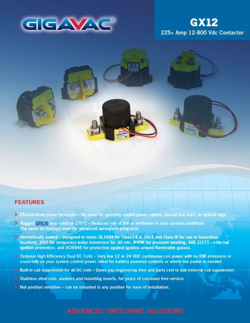
G X12<br />
225+ Amp 12-800 Vdc <strong>Contactor</strong><br />
Chassis level power terminals – No need for specially routed power cables, special bus bars, or special lugs.<br />
Rugged <strong>EPIC</strong>® seal rated to 175°C – Reduced risk of fire or meltdown in over current conditions.<br />
The same technology used for advanced aerospace programs.<br />
Hermetically sealed – Designed to meet: UL1604 for Class I & II, Div 2 and Class III for use in hazardous<br />
locations, IP67 for temporary water immersion for 30 min, IP69K for pressure washing, SAE J1171 - external<br />
ignition protection, and ISO8846 for protection against ignition around flammable gasses.<br />
Optional <strong>High</strong> Efficiency Dual <strong>DC</strong> Coils – Very low 12 or 24 V<strong>DC</strong> continuous coil power with no EMI emissions or<br />
cross-talk on your system control power. Ideal for battery powered systems or where low power is needed.<br />
Built-in coil suppression for all <strong>DC</strong> coils – Saves you engineering time and parts cost to add external coil suppression.<br />
Stainless steel nuts, washers and mounting inserts, for years of corrosion free service.<br />
Not position sensitive – can be mounted in any position for ease of installation.<br />
ADVANCED SWITCHING SOLUTIONS
PRODUCT SPECIFICATIONS<br />
Specifications<br />
Contact Arrangement<br />
Units Data<br />
Main Form X SPST-NO<br />
Auxilary (2A, 24V<strong>DC</strong>) 1 Form A or B SPST-NO or<br />
SPST-NC<br />
Mechanical Life<br />
Contact Resistance<br />
Cycles 1,000,000<br />
2<br />
Max mohms 0.4<br />
Typical mohms 0.15 to 0.3<br />
Insulation Resistance4 Mohms 100<br />
Dielectric At Sea Level (Leakage < 1mA) VRMS 2,200<br />
Shock, 1/2 Sine, 11ms G peak 20<br />
Vibration, Sinusoidal (500-2000 Hz Peak)<br />
Ambient Temp Range<br />
G 15<br />
Operating5 ˚C -55 to +85<br />
Storage ˚C -70 to +150<br />
Weight, Typical Kg (Lb) 0.5 (1.1)<br />
Environmental Seal Exceeds IP67 & IP69K<br />
Salt Fog MIL-STD-810<br />
COIL RATINGS at 25˚C<br />
225+ Amp 12-800 Vdc<br />
<strong>EPIC</strong>® Hermetic Sealed <strong>DC</strong> and AC <strong>Contactor</strong><br />
POWER SWITCHING AND<br />
CURRENT CARRY RATINGS<br />
1,000,000<br />
Coil P/N Designation B C F H J K L S T<br />
Coil Voltage, Nominal (V<strong>DC</strong>)<br />
12 24 48 72 120<br />
120<br />
VAC<br />
240<br />
VAC<br />
CYCLES<br />
100,000<br />
12 24<br />
Coil Voltage, Max (V) 16 32 64 96 140 140 280 16 32<br />
10,000<br />
Pick-Up Voltage, Max (V) 7 7.5 15 28 46 72 80 144 96, 8 6, 8 15<br />
Drop-Out Voltage, Max (V) 7 3 7 10 14 18 30 56 4.5 7<br />
Drop-Out Voltage, Min (V) 7 0.5 0.5 1.8 2.7 4.5 4.5 9 1 1.5<br />
Pick-Up Current, Max (A)<br />
(75 ms) 7 N/A N/A N/A N/A N/A N/A N/A 1.7 0.76<br />
Coil Current (A) 7 0.68 0.28 0.16 0.095 0.06 0.06 0.04 0.084 0.032<br />
Coil <strong>Power</strong> (W) 7 8 6.8 7.6 6.8 7.2 7.2 9.6 1 0.768<br />
Operate Time, Max (ms) 3 20 20 30 30 20 30 30 20 20<br />
Release Time, Max (ms) 12 12 12 12 12 50 55 12 12<br />
Internal Coil Suppression<br />
CONTROL CIRCUIT<br />
Coil Back EMF (V) 55 55 80 115 175 N/A N/A 55 55<br />
Transients, Max (V) (13 ms) N/A N/A N/A N/A N/A N/A N/A ±50 ±50<br />
Reverse Polarity (V) N/A N/A N/A N/A N/A N/A N/A 16 32<br />
1,000<br />
100<br />
<strong>DC</strong> POWER SWITCHING CYCLES 9<br />
G X12<br />
0 25 50 75 100 125 150 175 200 225<br />
TIME (sec)<br />
CURRENT (A)<br />
24V 300V 450V 600V<br />
10,000<br />
1,000<br />
100<br />
10<br />
CURRENT CARRY vs TIME<br />
with 85ºC terminal temperature rise<br />
375A max<br />
4/0 conductor<br />
350A max<br />
2/0 conductor<br />
0 500 1,000 1,500 2,000<br />
CURRENT (A)<br />
4/0 2/0<br />
<strong>GIGAVAC</strong>® - P.O. Box 4428 - Santa Barbara, CA 93140-4428 - ph +(805) 684-8401 - fax +(805) 684-8402<br />
info@gigavac.com - www.gigavac.com - ©Copyright 2003-2013 <strong>GIGAVAC</strong>, LLC.
DIMENSIONS<br />
Mounting<br />
M5 Bolts<br />
Case Material<br />
DuPont Zytel FR50<br />
(25% Glass Filled Nylon)<br />
<strong>Power</strong> Connection<br />
Zinc Plated, Grade 8, M10x1.5 Bolt<br />
Stainless M10x1.5 Nut<br />
Stainless Lock Washer<br />
Stainless Flat Washer<br />
Torque 14-20Nm [125-175in-lb]<br />
Coil Wire<br />
Silicone, 20 AWG, UL: VW-1<br />
2.35<br />
59.8<br />
1.15<br />
29.2<br />
.40<br />
10.2<br />
.98<br />
25<br />
.21<br />
5.3<br />
.95<br />
24.2<br />
MOUNTING<br />
225+ Amp 12-800 Vdc<br />
<strong>EPIC</strong>® Hermetic Sealed <strong>DC</strong> and AC <strong>Contactor</strong><br />
2.20<br />
55.9<br />
1.75<br />
44.5<br />
MOUNTING<br />
3.33<br />
84.6<br />
4.52<br />
114.8<br />
<strong>Power</strong> Contacts<br />
A2(+)<br />
A1(-)<br />
X2(-)<br />
X1(+)<br />
.87<br />
22<br />
1.75<br />
44.5<br />
MOUNTING<br />
2.25<br />
57.3<br />
Auxiliary contacts<br />
(optional)<br />
NO:<br />
NC:<br />
T1<br />
T2<br />
T1<br />
T2<br />
G X12<br />
<strong>GIGAVAC</strong>® - P.O. Box 4428 - Santa Barbara, CA 93140-4428 - ph +(805) 684-8401 - fax +(805) 684-8402<br />
info@gigavac.com - www.gigavac.com - ©Copyright 2003-2013 <strong>GIGAVAC</strong>, LLC.
PART NUMBER SYSTEM<br />
<strong>GX12</strong> B A B<br />
Coil Voltage B = 12 Vdc, Internal Coil<br />
Suppression<br />
Coil<br />
Termination<br />
Auxiliary<br />
Contact<br />
C = 24 Vdc, Internal Coil<br />
Suppression<br />
F = 48 Vdc, Internal Coil<br />
Suppression<br />
H = 72 Vdc, Internal Coil<br />
Suppression<br />
J = 120 Vdc, Internal<br />
Coil Suppression<br />
K = 120 Vac, Internal<br />
Coil Suppression<br />
L = 240 Vac, Internal<br />
Coil Suppression<br />
S = 12 Vdc, Low <strong>Power</strong>,<br />
Internal Coil Suppression<br />
T = 24 Vdc, Low <strong>Power</strong>,<br />
Internal Coil Suppression<br />
APPLICATION NOTES<br />
A = Flying leads<br />
38 cm (15 in)<br />
B = Flying leads<br />
61 cm (24 in)<br />
C = Flying leads<br />
122 cm (48 in)<br />
• <strong>Contactor</strong>s feature internal transorb for coil suppression. No external<br />
diodes should be added across the coil. The use of additional external<br />
coil suppression can slow the release time and invalidate the life cycle<br />
ratings, or can cause the contactor not to be able to interrupt the<br />
maximum current specified. If lower coil back EMF is required, please<br />
contact <strong>GIGAVAC</strong> for assistance.<br />
• <strong>Contactor</strong>s should be installed so that current flows from A2(+) to A1(-).<br />
<strong>Contactor</strong>s should not be switched bi-directionally.<br />
• Applications with capacitors will require a pre-charge circuit.<br />
Blank = None<br />
B = SPST,<br />
Normally Open<br />
C = SPST,<br />
Normally Closed<br />
• Electrical life rating is based on resistive load with 27µH maximum<br />
inductance in circuit. Because your application may be different, we<br />
suggest you test the contactor in your circuit to verify life is as required.<br />
• End of life is defined as when the dielectric, insulation resistance or<br />
contact resistance fails the specifications listed.<br />
225+ Amp 12-800 Vdc<br />
<strong>EPIC</strong>® Hermetic Sealed <strong>DC</strong> and AC <strong>Contactor</strong><br />
Notes & Definitions:<br />
1 Auxillary contact rating is 2A, 24Vdc Resistive load, 100,000<br />
cycles. Minimum current is 0.1mA, 5V. The auxiliary contact is<br />
mechanically linked to the main power contacts.<br />
2 Contact resisitance measured at currents higher than 100A.<br />
3 Operation time is measured at 25°C and includes maximum<br />
7ms bounce.<br />
4 Insulation resistance is 50 Mohms after life.<br />
5 <strong>Contactor</strong> can operate up to 125°C in special cases - contact<br />
<strong>GIGAVAC</strong> for details.<br />
6 <strong>Contactor</strong> has two coils. Both are used for pick-up, and<br />
then in approximately 75 milliseconds, one coil is electronically<br />
removed from the coil drive circuit. The remaining coil supplies<br />
low continuous hold power sufficient for the contactor to meet<br />
all of its specified performance specifications. This provides low<br />
coil power without PWM electronics that can cause EMI emissions<br />
and/or cross-talk on control power.<br />
7 <strong>Contactor</strong> is operated by a coil that changes resistance<br />
with temperature. Since pick-up current, coil current and coil<br />
power are specified at nominal voltage, they will be lower than<br />
indicated at temperatures above 25°C and higher than indicated<br />
at temperatures below 25°C. Similarly, pick-up and drop-out<br />
voltages will be higher than indicated at temperatures above<br />
25°C and lower than indicated at temperatures below 25°C.<br />
8 For pick-up testing of contactors with dual coils, the voltage<br />
can not be ramped up slowly, but must be applied instantly to at<br />
least the maximum pick-up voltage. Otherwise, the contactor will<br />
not pick-up.<br />
9 Limit make current to 500A to avoid contact welding. For AC<br />
power switching cycles, contact factory.<br />
G X12<br />
<strong>GIGAVAC</strong>® - P.O. Box 4428 - Santa Barbara, CA 93140-4428 - ph +(805) 684-8401 - fax +(805) 684-8402<br />
info@gigavac.com - www.gigavac.com - ©Copyright 2003-2013 <strong>GIGAVAC</strong>, LLC.