Low Voltage Controls & Distribution - Siemens Answers - Siemens ...
Low Voltage Controls & Distribution - Siemens Answers - Siemens ...
Low Voltage Controls & Distribution - Siemens Answers - Siemens ...

Create successful ePaper yourself
Turn your PDF publications into a flip-book with our unique Google optimized e-Paper software.
<strong>Low</strong> <strong>Voltage</strong> <strong>Controls</strong> & <strong>Distribution</strong><br />
<strong>Answers</strong> for industry.<br />
SIRIUS<br />
Datasheet 2009<br />
s
Pressing, equipping, transporting. These functions run in<br />
many automated production environments. You’ll find<br />
everything that you need to switch, protect and start motors<br />
with the extensive portfolio of the modular SIRIUS system.<br />
Everything. Easy. SIRIUS<br />
For more than 110 years now we have been developing and<br />
manufacturing industrial control products. We have always<br />
followed the philosophy to make it easier to use-whether in<br />
the electrical cabinet, in the field or directly at the machine.<br />
Today we have combined our complete range of industrial<br />
controls under one star: SIRIUS<br />
An important element of our SIRIUS industrial controls is the<br />
extensive range of products that we can offer associated with<br />
protecting, controlling , switching motor loads and systems.<br />
From well-proven and reliable contactors through relays that<br />
are easy to use to our innovative SIRIUS SC solid-state<br />
switching devices for use in the toughest of the conditions.<br />
With SIRIUS you always switch simply, safely and reliably. With<br />
SIRIUS industrial controls, you can look to the future with<br />
confidence.<br />
2
S I R I U S I n d u s t r i a l C o n t r o l s<br />
1 Introduction<br />
<strong>Siemens</strong> Automation and Drives. Welcome.<br />
Sharpen your competitive edge. Totally Integrated<br />
Automation. Integrated energy distribution from a single<br />
source. Totally Integrated Power.<br />
<strong>Low</strong>-<strong>Voltage</strong> <strong>Controls</strong> and <strong>Distribution</strong> - The basis for<br />
progressive solutions.<br />
SIRIUS Industrial <strong>Controls</strong><br />
<strong>Low</strong>-<strong>Voltage</strong> Power <strong>Distribution</strong><br />
2<br />
2a<br />
3<br />
3a<br />
4<br />
4a<br />
5<br />
5a<br />
<strong>Controls</strong> -<br />
Contactors and Contactor Assemblies<br />
3RT Air break contactors for switching motors<br />
3RT and 3TF vacuum contactors for switching motors<br />
3RA13, 3RA14, Contactor Assemblies<br />
3RT, 3RH, 3TC, 3TK Contactors for Special Applications<br />
3RH Contactor Relays and Latched Contactor Relays<br />
<strong>Controls</strong> - (Technical Information)<br />
Contactors and Contactor Assemblies<br />
3RT Air break contactors for switching motors<br />
3RT and 3TF vacuum contactors for switching motors<br />
3RA13, 3RA14, Contactor Assemblies<br />
3RT, 3RH, 3TC, 3TK Contactors for Special Applications<br />
3RH Contactor Relays and Latched Contactor Relays<br />
Protection Equipment<br />
3RV Motor Protection Circuit Breaker<br />
3RB2 Microprocessor based Overload Relays<br />
3RU1 Thermal Overload Relays<br />
Protection Equipment<br />
(Technical Information)<br />
3RV Motor Protection Circuit Breaker<br />
3RB2 Microprocessor based Overload Relays<br />
3RU1 Thermal Overload Relays<br />
Soft Starters and Motor Starters<br />
3RW Soft Starters<br />
3RE Encapsulated Starters<br />
Soft Starters and Motor Starters<br />
(Technical Information)<br />
3RW Soft Starters<br />
3RE Encapsulated Starters<br />
Monitoring and Control Devices<br />
SIMOCODE 3UF Motor Management and Control Devices<br />
3UG Monitoring Relays for Electrical and Additional Measurements<br />
3RN1 Thermistor Motor Protection<br />
3TK28 Safety Relays<br />
Monitoring and Control Devices<br />
(Technical Information)<br />
SIMOCODE 3UF Motor Management and Control Devices<br />
3UG Monitoring Relays for Electrical and Additional Measurements<br />
3RN1 Thermistor Motor Protection<br />
3TK28 Safety Relays<br />
3
Explanations<br />
General information<br />
Dimensions<br />
ATEX explosion protection<br />
4<br />
All dimensions in mm.<br />
In many industries the production, processing, transport and<br />
storage of combustible substances are accompanied by<br />
escaping gases, vapor or spray which find their way into the<br />
environment. Other processes result in combustible dust.<br />
Together with the oxygen in the air, the result can be an<br />
explosive atmosphere which will explode if ignited.<br />
Serious injury to persons and damage to property can result<br />
particularly in the chemical and petrochemical industry,<br />
mineral oil and natural gas production, mining, mills (e.g.<br />
grain, solid materials) and many other sectors.<br />
To guarantee the maximum possible safety in these areas, the<br />
legislators of most countries have drawn up requirements in<br />
the form of laws, regulations and standards. In the course of<br />
globalization, great progress has been made with regard to<br />
uniform directives for explosion protection.<br />
With Directive 94/9/EC, the European Union laid the<br />
foundations for complete harmonization by requiring that all<br />
new devices as from 1st July 2003 have to be approved in<br />
accordance with this directive.<br />
Devices approved according to UL standards<br />
UL standards are applied in North America and a number of<br />
other countries. This is important in particular for European<br />
exports of electrical switchgear and machine-integrated<br />
equipment, above all to the USA. Acceptance and delivery are<br />
possible only if the relevant UL standards are satisfied.<br />
UL 508A describes the design of control cabinets and the use<br />
of builtin components, sometimes with reference to other UL<br />
standards. As such, this standard represents the basis for all<br />
electrical systems used in North America.<br />
Numerous SIRIUS, SENTRON, SIVACON, ALPHA and BETA<br />
devices comply with UL standards and can thus be used worldwide<br />
in IEC/EN as well as UL applications within the scope of<br />
the defined application.<br />
With our products for low-voltage control and low-voltage<br />
circuit protection it is easy to build control cabinets according<br />
to UL standard.<br />
The range of low-voltage control products according to UL<br />
standard includes our SENTRON circuit breakers and SIRIUS<br />
controls - everything from motor-protective circuit breakers and<br />
starters to contactors, overload relays, and not forgetting our<br />
SIRIUS transformers and filters.<br />
In this catalog, special attention is drawn to devices which<br />
comply with the ATEX Directive. However, it does not replace<br />
intensive study of the relevant fundamentals and directives<br />
when planning and installing electrical systems.<br />
Also in our product range are SENTRON switch disconnectors<br />
and various SIRIUS detecting devices and command devices.<br />
<strong>Distribution</strong> functions can be performed with our busbar<br />
systems and terminal blocks.<br />
And of course our offering also includes miniature circuit<br />
breakers and fuses.
Introduction<br />
1<br />
1/2 Automation and Drives. Welcome<br />
1/4 Sharpen your competitive edge. Totally<br />
Integrated Automation<br />
1/6 Integrated energy distribution from a<br />
single source. Totally Integrated Power<br />
1/8 <strong>Low</strong>-<strong>Voltage</strong> <strong>Controls</strong> and <strong>Distribution</strong>.<br />
The basis for progressive solutions.<br />
1/10 SIRIUS Industrial <strong>Controls</strong>.<br />
1/11 <strong>Low</strong>-<strong>Voltage</strong> Power <strong>Distribution</strong>.
1<br />
1/2<br />
<strong>Siemens</strong> Automation and Drives.<br />
Welcome<br />
More than 70,000 people aiming for the same goal:<br />
increasing your competitiveness. That’s <strong>Siemens</strong><br />
Automation and Drives.<br />
We offer you a comprehensive portfolio for sustained<br />
success in your sector, whether you’re talking<br />
automation engineering, drives or electrical<br />
installation systems. Totally Integrated Automation<br />
(TIA) and Totally Integrated Power (TIP) form the core<br />
of our offering. TIA and TIP are the basis of our<br />
integrated range of products and systems for the<br />
manufacturing and process industries as well as<br />
building automation. This portfolio is rounded off by<br />
innovative services over the entire life cycle of your<br />
plants.<br />
Learn for yourself the potential our products and<br />
systems offer. And discover how you can permanently<br />
increase your productivity with us.<br />
Your regional <strong>Siemens</strong> contact can provide more<br />
information. He or she will be glad to help.
1/3<br />
1
1<br />
Management Level<br />
Operations Level<br />
Control Level<br />
Field Level<br />
Totally<br />
Integrated<br />
Automation<br />
1/4<br />
Sharpen your competitive edge.<br />
Totally Integrated Automation<br />
With Totally Integrated Automation (TIA), <strong>Siemens</strong> is the only<br />
manufacturer to offer an integrated range of products and<br />
systems for automation in all sectors - from incoming goods to<br />
outgoing goods, from the field level through the production<br />
control level to connection with the corporate management<br />
level.<br />
On the basis of TIA, we implement solutions that are perfectly<br />
tailored to your specific requirements and are characterized by<br />
a unique level of integration. This integration not only ensures<br />
significant reductions in interface costs but also guarantees the<br />
highest level of transparency across all levels.<br />
ERP – Enterprise Resource Planning<br />
Ethernet<br />
MES – Manufacturing Execution Systems<br />
Ethernet<br />
SIMATIC PCS 7<br />
Process Control (DCS)<br />
Industrial Ethernet<br />
PROFIBUS PA<br />
HART<br />
Industrial Software for<br />
• Design and Engineering<br />
• Installation and Commissioning<br />
• Operation<br />
SINUMERIK<br />
Computer Numeric Control<br />
Process Instrumentation<br />
• Maintenance<br />
• Modernization<br />
and Upgrade<br />
SIMOTION<br />
Motion Control System<br />
SIMATIC Sensors<br />
AS-Interface
SIMATIC IT<br />
SIMATIC NET<br />
Industrial<br />
Communication<br />
SIMATIC Controllers<br />
Modular/Embedded/PC-based<br />
SIMATIC Distributed I/O<br />
It goes without saying that you profit from Totally Integrated<br />
Automation during the entire life cycle of your plants - from the<br />
first planning steps, through operation, right up to<br />
modernization. Consistent integration in the further<br />
development of our products and systems guarantees a high<br />
degree of investment security here.<br />
Totally Integrated Automation makes a crucial contribution<br />
towards optimizing everything that happens in the plant and<br />
thus creates the conditions for a significant increase in<br />
productivity.<br />
SIMATIC WinCC<br />
SCADA System<br />
SIMATIC HMI<br />
Human Machine Interface<br />
SINAMICS Drive Systems<br />
Safety Integrated<br />
SIRIUS Industrial <strong>Controls</strong><br />
SENTRON Switching Devices<br />
SIMOCODE pro<br />
Motor Management System<br />
PROFINET<br />
Industrial Ethernet<br />
PROFIBUS<br />
AS-Interface<br />
Totally<br />
Integrated<br />
Power<br />
KNX/EIB<br />
GAMMA instabus<br />
1/5<br />
1
1<br />
1/6<br />
Integrated energy distribution from a single source.<br />
Totally Integrated Power<br />
Totally Integrated Power (TIP) brings together all the<br />
components of electrical energy distribution into an integrated<br />
whole. Thus TIP provides the answer to growing market<br />
demands in the planning, construction and use of utility<br />
buildings and industrial buildings.<br />
On the basis of TIP, we offer integrated solutions for energy<br />
dis-tribution, from medium voltage to the power outlet. Totally<br />
Inte-grated Power is based here on integration in planning and<br />
configuring as well as on perfectly matched products and<br />
systems.<br />
Communication<br />
Process/production<br />
automation<br />
Products and systems<br />
Planning<br />
and configuration<br />
HMI Load Load<br />
Graphs Graphs Prognoses<br />
management<br />
PROCESS FIELD BUS<br />
U<br />
UI<br />
I cos o<br />
cos P o<br />
PW<br />
W<br />
£ 110 kV
Maintenance<br />
Substation Substation<br />
<strong>Distribution</strong><br />
Maintenance<br />
Maintenance<br />
task<br />
Hall Hall 1 Air Air conditioning system<br />
checkup<br />
<strong>Distribution</strong> 3 Replacing circuit<br />
breaker contacts contacts<br />
Infeed II II Replacing meters<br />
Message/ Message/<br />
error<br />
management<br />
Totally Integrated Power offers communication<br />
and software modules for connecting the energy<br />
distribution systems to industrial automation and<br />
building automation. This enables the<br />
implemen-tation of significant savings potential.<br />
Selective<br />
protection<br />
Protocols Power<br />
quality<br />
DATE:<br />
EMPLOYEE<br />
COST CENTER<br />
PAY PERIOD BEGINNING<br />
PAY PERIOD ENDING<br />
DATE<br />
SUN MON TUE WED THUR FRI SAT SUN TOTAL<br />
IN<br />
OUT<br />
IN<br />
OUT<br />
OVERTIME<br />
TOTAL HOURS<br />
DATE<br />
SUN MON TUE WED THUR FRI SAT SUN TOTAL<br />
IN<br />
OUT<br />
IN<br />
OUT<br />
OVERTIME<br />
TOTAL HOURS<br />
DATE<br />
SUN MON TUE WED THUR FRI SAT SUN TOTAL<br />
IN<br />
OUT<br />
IN<br />
OUT<br />
OVERTIME<br />
TOTAL HOURS<br />
CODES<br />
V=VACATION<br />
H=HOLIDAY<br />
S=SICK<br />
REGULAR HOLIDAY OTHER<br />
OVER THE HOURS<br />
SICK VACATION<br />
TIME & ONE-HALF<br />
Cost center center<br />
instabus EIB<br />
Building<br />
automation<br />
1/7<br />
1
1<br />
<strong>Low</strong>-<strong>Voltage</strong> <strong>Controls</strong> and <strong>Distribution</strong>.<br />
The basis for progressive solutions.<br />
Extremely high demands are made on modern low-<br />
voltage controls and distribution: users want cost-<br />
effective solutions that are easy to integrate in control<br />
cabinets, distribution boards and distributed systems<br />
and can communicate perfectly with each other.<br />
<strong>Siemens</strong> has the answer: SIRIUS industrial controls<br />
and low-voltage power distribution with SIVACON,<br />
SENTRON and SIMARIS.<br />
SIRIUS industrial controls<br />
The SIRIUS range has everything you need for switching,<br />
protecting and starting loads. Products for monitoring, control,<br />
detection, commanding, signaling and power supply round off<br />
the spectrum of in-dustrial controls. Combined with Totally<br />
Integrated Automation, Safety Integrated and ECOFAST, our<br />
product portfolio can be bundled to create optimized systems.<br />
All in all, <strong>Siemens</strong>provides innovative controls with modern<br />
features, such as integrated communication and safety<br />
technology that work to your advantage:<br />
The basis for ground-breaking integrated solutions.<br />
1/8<br />
SIRIUS modular system<br />
SIRIUS Safety Integrated<br />
product range
SIVACON 8PS busbar trunking systems<br />
SENTRON switching devices<br />
Software for power distribution<br />
<strong>Low</strong>-voltage power distribution with<br />
SIVACON, SENTRON and SIMARIS<br />
Non-residental buildings and industrial plants have one thing in<br />
common: without electricity, everything comes to a halt. The<br />
availability, safety and cost effectiveness of the power<br />
distribution system is of utmost importance – from the<br />
medium voltage supply point through to the socket outlet. And<br />
only integrated solutions can ensure maximum efficiency for<br />
planning, configuration and operation.<br />
The concept is called Totally Integrated Power from <strong>Siemens</strong>.<br />
Total integration in planning and configuration creates<br />
synergies and saves costs. Perfectly matched products and<br />
systems provide efficient engineering and reliable operation. In<br />
the field of low-voltage power distribution, the following<br />
product ranges are available:<br />
SIVACON: From flexible busbar trunking systems through to<br />
safe power distribution boards and motor control centers.<br />
SENTRON: From well-proven switch disconnectors through to<br />
intelligent circuit breakers.<br />
Software for power distribution: Everything for<br />
dimensioning, configuring, visualizing and controlling your<br />
power distribution.<br />
1/9<br />
1
1<br />
SIRIUS Industrial <strong>Controls</strong>.<br />
1/10<br />
From tried and tested and reliable contactors, over<br />
easy-to-use relays, through to our innovative solidstate<br />
switching devices for the harshest of<br />
environments - SIRIUS ensures safe and reliable<br />
switching.<br />
SIRIUS protection equipment stands for high system<br />
availability and effective motor and installation<br />
protection. SIRIUS overload relays ensure consistent<br />
motor protection, suitable for all requirements and<br />
all budgets. SIRIUS motor starter protectors offer<br />
reliable protection against short-circuits and<br />
overload. Protect all running equipment.<br />
Finally a truly comprehensive and perfectly matched<br />
range of switching and protection devices from the<br />
SIRIUS modular system: from fully mounted directon-line<br />
starters and reversing starters through to<br />
soft starters. And for distributed solutions with AS-<br />
Interface or PROFIBUS, please refer to the<br />
communication-capable SIRIUS motor starters.<br />
Whether you’re using our comprehensive SIRIUS<br />
monitoring relays, our intelligent and<br />
communication-capable motor management system<br />
SIMOCODE pro, or our wide range of safety relays -<br />
our easy-to-use devices enable extremely reliable<br />
monitoring and control of your motors and<br />
installations.<br />
ON or OFF – you decide – 24/7.<br />
Switching with SIRIUS.<br />
See Chapter 2<br />
Everything’s in safe hands.<br />
Protection with SIRIUS.<br />
See Chapter 3<br />
Everything’s up and running.<br />
Starting with SIRIUS.<br />
See Chapter 4<br />
Everything’s in sight.<br />
Monitoring and control with SIRIUS.<br />
See Chapter 5
Ultimate modularity for your control cabinet:<br />
the SIRIUS modular system<br />
Modular standard components, which are<br />
optimally coordinated, can be combined with<br />
ease and use the same accessories and<br />
maximize synergies. All this is provided by our<br />
tried and tested SIRIUS modular system for the<br />
simple design and setup of load feeders. Our<br />
system provides everything you need for<br />
switching, protection and starting of motors and<br />
installations. Only seven sizes are needed, for a<br />
performance range up to 250 kW/415 V.<br />
Systematically simple. SIRIUS and more.<br />
The fact that we are continually expanding and<br />
improving our SIRIUS modular system means<br />
that it is able to provide individual and costeffective<br />
solutions for those everyday problems<br />
faced in the field. Key features of all single<br />
components are their small footprint and high<br />
flexibility. Configuring, installing, wiring and<br />
servicing are extremely easy and timesaving to<br />
perform. Regardless of whether you want to<br />
design load feeders with motor starter<br />
protectors or overload relays, contactors or soft<br />
starters, the SIRIUS modular system range has<br />
the right product for every application.<br />
The SIRIUS modular<br />
system has everything<br />
you need for switching,<br />
protection and starting<br />
of motors<br />
1/11<br />
1
1<br />
SIRIUS Safety Integrated is safety-oriented control and distribution<br />
- consistent and innovative<br />
Communication-capable ECOFAST motor starters in IP65/76<br />
AS-Interface<br />
As a cost-effective and robust bus system at field level, AS-<br />
Interface connects actuators and sensors – from<br />
temperature sensor to motor starter – to the higher control<br />
level.<br />
For our complete AS-Interface product range for standard<br />
or safety applications we can provide you with a consistent<br />
and easy connection to PROFIBUS or PROFINET. AS-<br />
Interface: easy, safe, consistent!<br />
1/12<br />
SIRIUS Safety Integrated<br />
As part of our uniform safety systems - Safety<br />
Integrated, SIRIUS Safety Integrated covers safetyoriented<br />
controls and distribution in the field of<br />
industrial automation. For performing safety tasks<br />
at cell level - be they failsafe detecting,<br />
commanding and signaling, monitoring and<br />
evaluating or the startup and reliable shutdown of<br />
installations. Combined with standard fieldbus<br />
systems, such as AS-Interface and PROFIBUS, SIRIUS<br />
Safety Integrated can even solve networked safety<br />
tasks of considerable complexity.<br />
ECOFAST<br />
Modern field and power bus technologies open up a<br />
whole new world of options and up to now<br />
unknown saving potential. ECOFAST (Energy and<br />
Communication Field Installation System) is the<br />
distributed system solution with a standardized<br />
connection method for all components on the basis<br />
of distributed installation, and is equipped<br />
throughout for PROFIBUS DP and AS-Interface.<br />
System overview - AS-Interface
2<br />
<strong>Controls</strong> –<br />
Contactors and<br />
Contactor Assemblies<br />
2/2 Introduction<br />
3RT, 3TF Contactors<br />
for Switching Motors<br />
2/4 General data<br />
2/9 3RT10 contactors, 3-pole, 3 ... 250 kW<br />
2/16 3RT12 vacuum contactors, 3-pole, 110 ...<br />
250 kW<br />
2/17 3TF6 vacuum contactors, 3-pole, 335 ...<br />
450 kW<br />
3RA13, 3RA14 Contactor Assemblies<br />
3RA13 Reversing Contactor Assemblies<br />
2/18 3RA13 complete units, 3 ... 45 kW<br />
2/23 Components for customer assembly<br />
3RA14 Contactor Assemblies for Wye-<br />
Delta Starting<br />
2/26 3RA14 complete units, 3 ...75 kW<br />
2/33 Components for customer assembly<br />
3RT, 3RH, 3TC, 3TH, 3TK Contactors for<br />
Special Applications<br />
3RT14 Contactors for Switching Resistive<br />
Loads (AC-1)<br />
2/34 3-pole, 140 ... 690 A<br />
3RT13 Contactors for Switching Resistive<br />
Loads (AC-1)<br />
2/35 4-pole, 4 NO, 18 ... 140 A<br />
3TK1 Contactors for Switching Resistive<br />
Loads (AC-1)<br />
2/36 4-pole, 4 NO, 200 ... 1000 A<br />
3RT15 Contactors<br />
2/37 4-pole, 2 NO + 2 NC, 4 ... 18.5 kW<br />
3RT16 Capacitor Contactors<br />
2/38 12.5 ... 50 kvar<br />
3TC Contactors for Switching DC <strong>Voltage</strong><br />
2/39 1- and 2-pole, 32 ... 400 A<br />
2/41<br />
3RH, 3TH Contactor Relays<br />
3RH1 contactor relays, 4- and 8-pole<br />
2/42 3RH11 contactor relays<br />
2/43 3RH14 latched contactor relays, 4-pole<br />
2/44 3RH11 coupling relays for switching<br />
auxiliary circuits, 4-pole<br />
3RT Coupling Relays<br />
2/45 3RT10 coupling relays (interface), for<br />
switching motors, 3-pole, 3 ... 11 kW<br />
Accessories and Spare Parts<br />
For 3RT, 3RH Contactors and Contactor<br />
Relays<br />
2/46 Accessories for 3RT, 3RH contactors and<br />
contactor relays<br />
2/55 Spare parts for 3RT, 3RH contactors and<br />
contactor relays<br />
For 3T Contactors and Contactor Relays<br />
2/56 Spare parts for 3TC, 3TF, 3TK contactors
2<br />
<strong>Controls</strong> – Contactors and Contactor Assemblies<br />
Introduction<br />
Overview<br />
Size S00 S0 S2<br />
Type 3RT10 1 3RT10 2 3RT10 3<br />
3RT10 contactors · 3RT12 and 3TF68/69 vacuum contactors<br />
Type 3RT10 15 3RT10 16 3RT10 17 3RT10 23 3RT10 24 3RT10 25 3RT10 26 3RT10 34 3RT10 35 3RT10 36<br />
AC, DC operation (p. 2/12) (p. 2/13) (p. 2/13)<br />
Type — — —<br />
AC-3<br />
I e/AC-3/415 V A 7 9 12 9 12 17 25 32 40 50<br />
415 V kW 3 4 5.5 4 5.5 7.5 11 15 18.5 22<br />
230 V kW 2.2 3 3 3 3 4 5.5 7.5 11 15<br />
500 V kW 3.5 4.5 5.5 4.5 7.5 10 11 18.5 22 30<br />
690 V 3RT10/12 kW 4 5.5 5.5 5.5 7.5 11 11 18.5 22 22<br />
1 000 V 3RT10/12 kW — — — — — — — — — —<br />
AC-4 (for I a = 6 x I e)<br />
415 V kW 3 4 4 4 5.5 7.5 7.5 15 18.5 22<br />
415 V 3RT10/12 kW 1.15 2 2 2 2.6 3.5 4.4 8.2 9.5 12.6<br />
(200 000 operating cycles)<br />
AC-1 ( ≤ 690 V)<br />
I e 3RT10/12 A 18 22 22 40 40 40 40 50 60 60<br />
3RT14 AC-1 contactors<br />
Type — — —<br />
I e/AC-1/≤ 690 V A — — —<br />
Accessories for contactors<br />
Auxiliary switch blocks front 3RH19 11 (p. 2/47) 3RH19 21 (p. 2/47)<br />
lateral — 3RH19 21 (p. 2/47)<br />
Terminal covers — — 3RT19 36-4EA2 (p. 2/53)<br />
Box terminal blocks — — —<br />
Surge suppressors 3RT19 16 (p. 2/51) 3RT19 26 (p. 2/51) 3RT19 26/36 (p. 2/51)<br />
3RU1 and 3RB2 overload relays (protection equipment: overload relays)<br />
3RU11, thermal, CLASS 10 3RU11 16 0.1 ... 12 A (Chap. 3) 3RU11 26 1.8 ... 25 A (Chap. 3) 3RU11 36 5.5 ... 50 A (Chap. 3)<br />
3RB20/21, solid-state, 3RB20 16 0.1 ... 12 A (Chap. 3) 3RB20 26 3 ... 25 A (Chap. 3) 3RB20 36<br />
CLASS 5, 10, 20 and 30 3RB21 16 3RB21 26 3RB21 36 6 ... 50 A (Chap. 3)<br />
3RB22/23, solid-state, 3RB2. 83 + 3RB29 06 3RB2. 83 + 3RB29 06<br />
CLASS 5, 10, 20 and 30 0.3 ... 25 A (Chap. 3) 10 ... 100 A(Chap. 3)<br />
3RV10 motor starter protectors (protection equipment: motor starter protectors)<br />
Type 3RV10 11 0.18 ... 12 A (Chap. 3) 3RV10 21 9 ... 25 A (Chap. 3) 3RV10 31 22 ... 50 A (Chap. 3)<br />
Link modules 3RA19 11 (Chap. 3) 3RA19 21 (Chap. 3) 3RA19 31 (Chap. 3)<br />
3RA13 reversing contactor assemblies<br />
Complete units Type 3RA13 15 3RA13 16 3RA13 17 3RA13 24 3RA13 25 3RA13 26 3RA13 34 3RA13 35 3RA13 36<br />
(p. 2/19) (p. 2/20) (p. 2/21)<br />
400 V kW 3 4 5.5 5.5 7.5 11 15 18.5 22<br />
Installation kits/wiring modules 3RA19 13-2A (p. 2/24) 3RA19 23-2A (p. 2/24) 3RA19 33-2A (p. 2/24)<br />
Mechanical interlocks 3RA19 12-2H (p. 2/25) 3RA19 24-1A/-2B (p. 2/23)<br />
3RA14 contactor assemblies for wye-delta starting<br />
Complete units Type 3RA14 15 3RA14 16 3RA14 23 3RA14 25 3RA14 34 3RA14 35 3RA14 36<br />
(p. 2/28) (p. 2/29) (p. 2/30, 2/31)<br />
400 V kW 5.5 7.5 11 15/18.5 22/30 37 45<br />
Installation kits/wiring modules 3RA19 13-2B (p. 2/33) 3RA19 23-2B (p. 2/33) 3RA19 33-2B/-2C (p. 2/33)<br />
2/2
<strong>Controls</strong> – Contactors and Contactor Assemblies<br />
S3 S6 S10 S12 14<br />
3RT1. 4 3RT1. 5 3RT1. 6 3RT1. 7 3TF6<br />
3RT10 44 3RT10 45 3RT10 46 3RT10 54 3RT10 55 3RT10 56 3RT10 64 3RT10 65 3RT10 66 3RT10 75 3RT10 76 —<br />
(p. 2/13) (p. 2/14) (p. 2/14) (p. 2/14)<br />
Introduction<br />
— — 3RT12 64 3RT12 65 3RT12 66 3RT12 75 3RT12 76 3TF68 3TF69<br />
(p. 2/16) (p. 2/16) (p. 2/17)<br />
65 80 95 115 150 185 225 265 300 400 500 630 820<br />
30 37 45 55 75 90 110 132 160 200 250 335 450<br />
18.5 22 22 37 45 55 55 75 90 132 160 200 260<br />
37 45 55 75 90 110 160 160 200 250 355 434 600<br />
45 55 55 110 132 160 200 250 250 400 400/500 600 800<br />
30 37 37 75 90 90 90/315 132/355 132/400 250/560 250/710 600 800<br />
30 37 45 55 75 90 110 132 160 200 250 355 400<br />
15.1 17.9 22 29 38 45 54/78 66/93 71/112 84/140 98/161 168 191<br />
100 120 120 160 185 215 275/330 330 330 430/610 610 700 910<br />
3RT14 46 (p. 2/34) 3RT14 56 (p. 2/34) 3RT14 66 (p. 2/34) 3RT14 76 (p. 2/34) —<br />
140 275 400 690 —<br />
—<br />
3TY7 561 (p. 2/59)<br />
3RT19 46-4EA1/2 (p. 2/53) 3RT19 56-4EA1/2/3 (p. 2/53) 3RT19 66-4EA1/2/3 (p. 2/53) 3TX7 686/696 (p. 2/57)<br />
— 3RT19 55/56-4G (p. 2/53) 3RT19 66-4G (p. 2/53) —<br />
3RT19 56-1C (RC element) (p. 3/108) — (p. 2/56)<br />
3RU11 46 18 ... 100 A (Chap. 3) — — — —<br />
3RB20 46 12.5 ... 100 A (Chap. 3) 3RB20 56 50 ... 200 A(Chap. 3) 3RB20 66 55 ... 630 A (Chap. 3) 3RB20 66 160 ... 630 A 3RB20 66 160 ... 630 A<br />
3RB21 46 3RB21 56 3RB21 66 3RB21 66 (Chap. 3) 3RB21 66 (Chap. 3)<br />
3RB2. 83 + 3RB29 56 3RB2. 83 + 3RB29 66<br />
20 ... 200 A(Chap. 3) 63 ... 630 A (Chap. 3)<br />
3RV10 41 45 ... 100 A (Chap. 3) — — — —<br />
3RA19 41 (Chap. 3) — — — —<br />
3RA13 44<br />
(p. 2/22)<br />
3RA13 45 3RA13 46 — — — —<br />
30 37 45 55 75 90 110 132 160 200 250 335<br />
3RA19 43-2A (p. 2/24) 3RA19 53-2A (p. 2/24) 3RA19 63-2A (p. 2/24) 3RA19 73-2A (p. 2/24) 3TX7 680-1A<br />
3RA19 54-2A (p. 2/23) 3TX7 686-1A<br />
3RA14 44<br />
(p. 2/32)<br />
3RA14 45 — — — —<br />
55 75 — — — 630<br />
3RA19 43-2B/-2C (p. 2/33) 3RA19 53-2B (p. 2/33) 3RA19 63-2B (p. 2/33) 3RA19 73-2B (p. 2/33) 3TX7 680-1B<br />
2/3<br />
2
2<br />
3RT Contactors for Switching Motors<br />
General data<br />
Overview<br />
3RT1 contactors and coupling relays<br />
Size S00 with mountable accessories<br />
The SIRIUS generation of<br />
controls is a complete,<br />
modular system family, 3<br />
logically designed right<br />
down to the last detail,<br />
from the basic units<br />
to the accessories.<br />
1 Contactor (page 2/12)<br />
2 Coupling relay (page 2/45)<br />
3 Solid-state time-delay block, ON-delay (page 2/50)<br />
4 Solid-state time-delay block, OFF-delay (page 2/50)<br />
5 Auxiliary switch block with solid-state time delay (page 2/48)<br />
(ON or OFF-delay or wye-delta function)<br />
6 1-pole auxiliary switch block, cable entry from above (page 2/47)<br />
7 4-pole auxiliary switch block (terminal designations according to<br />
EN 50005) (page 2/47)<br />
8 2-pole auxiliary switch block, standard version or solid-state time-delay<br />
version (pages 2/48) (terminal designations according to EN 50005)<br />
9 Surge suppressor with LED (page 2/51)<br />
For contactor assemblies see pages 2/18 to 2/33. For<br />
installation kit for reversing contactor assemblies (mech.<br />
interlocking, wiring modules) see pages 2/24, 2/25. For<br />
mountable overload relays see Protection Equipment: Overload<br />
Relays.<br />
2/4<br />
5<br />
6<br />
7<br />
4<br />
8<br />
10<br />
1<br />
11<br />
12<br />
10 3-phase feeder terminal (page 2/33)<br />
11 Link for paralleling (star jumper), 3-pole, without terminal (page 2/33)<br />
12 Link for paralleling, 3-pole, with terminal (page 2/52)<br />
13 Link for paralleling, 4-pole, with terminal (page 2/52)<br />
13<br />
For contactors<br />
For contactors and coupling relays (interface)<br />
9<br />
2<br />
NSB0_00448a
3RT1 contactors<br />
Sizes S0 to S3 with mountable accessories<br />
4<br />
19<br />
6<br />
7<br />
12<br />
5<br />
8<br />
11<br />
17<br />
1 Contactor, size S0, see page 2/13<br />
2 Contactor, size S2, see page 2/13<br />
3 Contactor, size S3, see page 2/13<br />
14<br />
For sizes S0 to S3:<br />
4 Solid-state time-delay block, ON-delay (page 2/50)<br />
5 Solid-state time-delay block, OFF-delay (page 2/50)<br />
6 Auxiliary switch block with solid-state time delay (page 2/49)<br />
(ON or OFF-delay or wye-delta function)<br />
7 2-pole auxiliary switch block, cable entry from above (page 2/47)<br />
8 4-pole auxiliary switch block (page 2/47)(terminal designations<br />
according to EN 50012 or EN 50005)<br />
9 Link for paralleling (star jumper), 3-pole, without connection terminal<br />
(page 2/33)<br />
10 Link for paralleling, 3-pole, with terminal (page 2/52)<br />
11 2-pole auxiliary switch block, laterally mountable left or right (page<br />
2/48) (terminal designations according to EN 50012 or EN 50005)<br />
12 Single-pole auxiliary switch block (up to 4 can be snapped on) (page 2/47)<br />
13 Mechanical interlock, laterally mountable (page 2/23)<br />
14 Mechanical interlock, mountable on the front (page 2/23)<br />
20<br />
1<br />
16<br />
18<br />
15<br />
16<br />
13<br />
9<br />
3RT Contactors for Switching Motors<br />
10<br />
1<br />
21<br />
22<br />
21<br />
3<br />
2<br />
General data<br />
15 Wiring modules on the top and bottom (reversing duty) (page 2/24)<br />
16 Surge suppressor (page 2/51) (varistor, RC element, diode assembly),<br />
can be mounted on the top or bottom (different for S0 and S2/S3)<br />
17 Coupling link for mounting directly onto contactor coil (page 2/52)<br />
18 LED module for indicating contactor operation (page 2/52)<br />
Only for size S0:<br />
19 Pneumatic delay block (page 2/50)<br />
Only for sizes S0 and S2:<br />
20 Mechanical latching (page 2/50)<br />
Only for sizes S2 and S3:<br />
21 Terminal cover for box terminals (page 2/53)<br />
Only for size S3:<br />
22 Terminal cover for cable lugs and busbar connections (page 2/53)<br />
Accessories identical for sizes S0 to S3<br />
Accessories differ according to size<br />
NSB0_00449b<br />
2/5<br />
2
2<br />
3RT Contactors for Switching Motors<br />
General data<br />
3RT1 contactors<br />
Sizes S6 to S12 with accessories<br />
(illustration for basic unit)<br />
2<br />
4<br />
5<br />
2/6<br />
3<br />
6<br />
1 3RT10 and 3RT14 air-break contactor, sizes S6, S10 and S12<br />
(page 2/14)<br />
1<br />
2 Auxiliary switch block with solid-state time delay (page 2/49)<br />
(ON or OFF-delay or wye-delta function)<br />
3 4-pole auxiliary switch block (page 2/47)<br />
(terminal designations according to EN 50012 or EN 50005)<br />
4 2-pole auxiliary switch block, cable entry from above (page 2/47)<br />
5 Single-pole auxiliary switch block (up to 4 can be snapped on)<br />
(page 2/47)<br />
6 2-pole auxiliary switch block, laterally mountable left or right (page<br />
2/48) (terminal designations according to EN 50012 or EN 50005)<br />
(identical for S0 to S12)<br />
7 Surge suppressor (RC element) (page 2/51), for plugging into top of<br />
withdrawable coil<br />
For mountable overload relays see Protection Equipment:<br />
Overload Relays.<br />
7<br />
8<br />
9<br />
10<br />
NSB0_01157c<br />
8 Terminal cover for cable lug and busbar connection (page 2/53),<br />
different for sizes S6 and S10/S12<br />
9 Terminal cover for box terminal, (page 2/53), different for sizes S6 and<br />
S10/S12<br />
10 Box terminal block (page 2/53), different for sizes S6 and S10/S12<br />
Accessories identical for sizes S0 to S12<br />
Accessories identical for sizes S6 to S12<br />
Accessories differ according to size
3RA1 contactor assemblies, 3RT1 contactors<br />
Sizes S6, S10 and S12 with accessories<br />
1<br />
3<br />
3<br />
1 3RT10 and 3RT14 air-break contactor, sizes S6, S10 and S12 (page 2/14<br />
and 2/34) or 3RT12 vacuum contactor, sizes S10 and S12 (page 2/16)<br />
2 Mechanical interlock, laterally mountable (page 2/23)<br />
3 3RA19 wiring modules on the top and bottom (page 2/24)<br />
4 3RT19 56-4BA31 link for paralleling (star jumper), 3-pole, with through<br />
hole (page 2/52)<br />
5 Terminal cover for box terminal, (page 2/53), different for sizes S6 and<br />
S10/S12<br />
6 Terminal cover for cable lug and busbar connection (page 2/53),<br />
different for sizes S6 and S10/S12<br />
For mountable overload relays see Protection Equipment:<br />
Overload Relays.<br />
2<br />
1<br />
4<br />
3RT Contactors for Switching Motors<br />
5<br />
6<br />
NSB0_01669<br />
Accessories identical for sizes S6 to S12<br />
Accessories differ according to size<br />
General data<br />
2/7<br />
2
2<br />
3RT Contactors for Switching Motors<br />
General data<br />
3RT1 contactors<br />
Sizes S6 to S12 with accessories<br />
1 Air-break contactor, sizes S6, S10 and S12 (page 2/15)<br />
2 Vacuum contactor, sizes S10 and S12 (page 2/16)<br />
3 Withdrawable coils for 3RT1. ..-.A.. contactors with conventional<br />
operating mechanism (Size S10: differentiation between 3RT10/3RT14<br />
air-break contactors and 3RT12 vacuum contactors)<br />
(Size S12: the same for air-break and vacuum contactors)<br />
4 Withdrawable coils for 3RT1. ..-.N.. contactors with solid-state<br />
operating mech-anism (Size S10: differentiation between 3RT10/3RT14<br />
air-break contactors and 3RT12 vacuum contactors)<br />
(Size S12: the same for air-break and vacuum contactors)<br />
5 Withdrawable coils and laterally mountable module (plug-on) for 3RT1.<br />
..-.P.. and 3RT1. ..-.Q.. air-break contactors with solid-state operating<br />
mechanism and remaining lifetime indicator<br />
6 Surge suppressor (RC element) (page 2/51),<br />
plug-mountable on withdrawable coils<br />
• 3RT1...-.A.. with conventional operating mechanism<br />
• 3RT1...-.N.. with solid-state operating mechanism<br />
Identical for sizes S6 to S12<br />
Different according to size<br />
For mountable overload relays see Protection Equipment:<br />
Overload Relays.<br />
2/8
Overview<br />
3RT10 contactors, 3-pole, sizes S00 to S3, up to 45 kW<br />
AC and DC operation<br />
IEC 60947, EN 60947 (VDE 0660)<br />
The 3RT1 contactors are climate-proof. They are finger-safe<br />
according to EN 50274.<br />
Size S00 contactors have an auxiliary contact integrated in the<br />
basic unit. The basic units of sizes S0 to S3 contain only the<br />
main current paths.<br />
All basic units can be extended with auxiliary switch blocks.<br />
For size S0 and higher, complete units with 2 NO + 2 NC are<br />
available (connection designation according to EN 50012). The<br />
auxiliary switch block can be removed.<br />
Contact reliability<br />
If voltages ≤ 110 V and current ≤ 100 mA are to be switched,<br />
the auxiliary contacts of the 3RT1 contactor or 3RH11 contactor<br />
relay should be used as they guarantee a high level of contact<br />
reliability.<br />
These auxiliary contacts are suitable for solid-state circuits with<br />
currents ≥ 1 mA at a voltage of 17 V.<br />
Short-circuit protection of the contactors<br />
For more information about short-circuit protection of<br />
contactors without overload relay, see Technical specifications.<br />
For short-circuit protection of the contactors with overload<br />
relay, see “Overload Relays”. To assemble fuseless motor<br />
feeders you must select combinations of motor starter protector<br />
and contactor as explained in “Fuseless Load Feeders”.<br />
Motor protection<br />
3RU11 thermal overload relays or 3RB20 solid-state overload<br />
relays can be fitted to the 3RT1 contactors for protection<br />
against overload. The overload relays must be ordered<br />
separately.<br />
Ratings of induction motors<br />
The quoted rating (in kW) refers to the output power on the<br />
motor shaft (according to the nameplate).<br />
Surge suppression<br />
3RT1 contactors can be retrofitted with RC elements, varistors,<br />
diodes or diode assemblies (assembly of diode and Zener diode<br />
for short break times) for damping opening surges in the coil.<br />
The surge suppressors are plugged onto the front of size S00<br />
contactors. Space is provided for them next to a snap-on<br />
auxiliary switch block.<br />
For size S0 to S3 contactors, varistors and RC elements can be<br />
snapped on either on the top or directly below the coil<br />
terminals. Diode assemblies are available in 2 different versions<br />
on account of their polarity. Depending on the application they<br />
can be connected either only at the bottom (assembly with<br />
motor starter protector) or only at the top (assembly with<br />
overload relay).<br />
The plug-in direction of the diodes and diode assemblies is<br />
specified by coding.<br />
3RT Contactors for Switching Motors<br />
3RT10 contactors, 3-pole, 3 ... 250 kW<br />
Exceptions:<br />
3RT19 26-1T . 00 and<br />
3RT19 36-1T . 00, in this case the plug-in direction is marked<br />
with “+” and “-”.<br />
Coupling relays are supplied either without surge suppression<br />
or with a varistor or diode connected as standard, according to<br />
the version.<br />
Note:<br />
The OFF-delay times of the NO contacts and the ON-delay<br />
times of the NC contacts increase if the contactor coils are<br />
damped against voltage peaks (noise suppression diode 6 to<br />
10 times; diode assemblies 2 to 6 times, varistor +2 to 5 ms).<br />
3RT10 contactors, 3-pole, sizes S6 to S12,<br />
> 45 to 250 kW<br />
• 3RT10, contactors for switching motors,<br />
• 3RT12, vacuum contactors for switching motors,<br />
• 3RT14, contactors for AC-1 applications.<br />
Operating mechanism types<br />
Two types of solenoid operation are available:<br />
• Conventional operating mechanism<br />
• Solid-state operating mechanism (with 3 performance levels)<br />
UC operation<br />
The contactors can be operated with AC (40 to 60 Hz) as well<br />
as with DC.<br />
Withdrawable coils<br />
For simple coil replacement, e.g. if the application is replaced,<br />
the magnetic coil can be pulled out upwards after the release<br />
mechanism has been actuated and can be replaced by any<br />
other coil of the same size.<br />
Auxiliary contact complement<br />
The contactors can be fitted with up to 8 auxiliary contacts<br />
(identical auxiliary switch blocks from S0 to S12). Of these, no<br />
more than 4 are permitted to be NC contacts.<br />
3RT10 and 3RT14 contactors:<br />
auxiliary contacts mounted laterally and on front<br />
3RT12 vacuum contactors:<br />
auxiliary contacts mounted laterally<br />
Contactors with conventional operating mechanism<br />
3RT1 . . . - . A version:<br />
The magnetic coil is switched directly on and off with the<br />
control supply voltage Us by way of terminals A1/A2.<br />
Multi-voltage range for the control supply voltage Us: Several closely adjacent control supply voltages, available<br />
around the world, are covered by just one coil,<br />
for example 110-115-120-127 V UC or 220-230-240 V UC.<br />
In addition, allowance is also made for a coil operating range of<br />
0.8 times the lower (Us min) and 1.1 times the upper (Us max)<br />
rated control supply voltage within which the contactor<br />
switches reliably and no thermal overloading occurs.<br />
2/9<br />
2
2<br />
3RT Contactors for Switching Motors<br />
3RT10 contactors, 3-pole, 3 ... 250 kW<br />
Contactors with solid-state operating mechanism<br />
The magnetic coil is supplied selectively with the power<br />
required for reliable switching and holding by upstream control<br />
electronics.<br />
• Wide voltage range for the control supply voltage Us: Compared with the conventional operating mechanism, the<br />
solid-state operating mechanism covers an even broader<br />
range of control supply voltages used worldwide within one<br />
coil variant.<br />
For example, the coil for 200 to 277 V UC (Us min to Us max)<br />
covers the voltages 200-208-220-230-240-254-277 V used<br />
worldwide.<br />
• Extended operating range 0.7 to 1.25 x U s:<br />
The wide range for the rated control supply voltage and the<br />
additionally allowed coil operating range of 0.8 x U s min to<br />
1.1 x U s max results in an extended coil operating range of at<br />
least 0.7 to 1.25 x U s, within which the contactors will<br />
operate reliably, for the most common control supply<br />
voltages of 24, 110 and 230 V.<br />
• Bridging temporary voltage dips:<br />
Control voltage failures dipping to 0 V (at A1/A2) are bridged<br />
for up to approx. 25 ms to avoid unintentional tripping.<br />
• Defined ON and OFF thresholds:<br />
For voltages of ≥ 0.8 x U s min and higher the electronics will<br />
reliably switch the contactor ON, and as of ≤ 0.5 x U s min it is<br />
reliably switched OFF. The hysteresis in the switching<br />
thresholds prevents the main contacts from chattering as well<br />
as increased wear or welding when operated in weak,<br />
unstable networks. This also prevents thermal overloading of<br />
the contactor coil if the voltage applied is too low (contactor<br />
does not close properly and is continuously operated with<br />
overexcitation).<br />
• <strong>Low</strong> control power consumption when closing and in the<br />
closed state.<br />
Electromagnetic compatibility (EMC)<br />
The contactors with solid-state operating mechanism comply<br />
with the requirements for operation in industrial plants.<br />
• Interference immunity<br />
- burst (IEC 61000-4-4): 4 kV<br />
- surge (IEC 61000-4-5): 4 kV<br />
- electrostatic discharge, ESD (IEC 61000-4-2): 8/15 kV<br />
- electromagnetic field (IEC 61000-4-3): 10 V/m<br />
• Emitted interference<br />
- limit value class A according to EN 55011<br />
Note:<br />
In connection with converters, the control cables should be<br />
installed separately from the load cables of the converter.<br />
Indication of remaining lifetime (RLT)<br />
Main contactor contacts are working parts which must be<br />
replaced in good time when the end of their service life has<br />
been reached. The degree of contact erosion and thus the<br />
electrical endurance (= number of operating cycles) depends on<br />
the loading, utilization category, operating mode, etc. Routine<br />
checks/visual inspections by the maintenance personnel are<br />
needed in order to monitor the state of the main contacts. The<br />
remaining lifetime indication function takes over this task. It<br />
does not count the number of operating cycles – which does<br />
not provide information about contact erosion – but instead<br />
electronically identifies, evaluates and stores the actual<br />
progress of erosion of each one of the three main contacts, and<br />
2/10<br />
outputs a warning when specified limits are reached. The stored<br />
data are not lost even if the control supply voltage for A1/A2<br />
fails. After replacement of the main contacts, measurement<br />
the remaining lifetime must be reset using the “RESET” button<br />
(hold down RESET button for about 2 seconds using a pen or<br />
similar tool).<br />
Advantages:<br />
• Signaling through relay contact or AS-i when remaining<br />
lifetime is 20 %, i.e. contact material wear is 80 %<br />
• Additional visual indication of various levels of erosion by<br />
means of LEDs on the laterally mounted solid-state module<br />
when remaining lifetime is 60 % (green), 40 % (orange) and<br />
20 % (red)<br />
- , A M<br />
, E I F = O I<br />
C H A A <br />
C H A A <br />
H = C A "<br />
H A @<br />
4 6<br />
$<br />
4 A I A J<br />
4 6<br />
$<br />
"<br />
$<br />
4 A I A J<br />
• Early warning to replace contacts<br />
4 6<br />
$<br />
"<br />
"<br />
4 A I A J<br />
• Optimum utilization of contact material<br />
4 6<br />
$<br />
"<br />
4 A I A J<br />
5 * # =<br />
• Visual inspection of the condition of contacts no longer<br />
necessary<br />
• Reduction of ongoing operating costs<br />
• Optimum planning of maintenance measures<br />
• Avoidance of unforeseen plant downtimes<br />
3RT1 . . . - . N version: for 24 V DC PLC output<br />
2 control options:<br />
• Control without a coupling link directly through a 24 V DC/<br />
≥ 30 mA PLC output (EN 61131-2). Connection by means of<br />
2-pole plug-in connection. The screwless spring-type<br />
connection is part of the scope of supply. The control supply<br />
voltage which supplies the solenoid operating mechanism<br />
must be connected to A1/A2.<br />
Note:<br />
Before start-up, the slide switch for PLC operation must be<br />
moved to the “PLC ON” position (setting ex works: “PLC OFF”).<br />
2<br />
1<br />
L1/L+<br />
N/L-<br />
PLC output<br />
DC 24 V/30 mA<br />
PLC<br />
OFF ON<br />
DC 24 V<br />
A1 A2<br />
NSB0_01143c<br />
Slide switch must be in<br />
“PLC ON” position<br />
Plug-in connection, 2-pole<br />
• Conventional control by applying the control supply voltage<br />
at A1/A2 through a switching contact.
Note:<br />
The slide switch must be in the “PLC OFF” position<br />
(= setting ex works)<br />
<br />
<br />
2 +<br />
. . <br />
) )<br />
, + " 8<br />
5 * " " ?<br />
Slide switch must be in<br />
“PLC OFF” position<br />
3RT1 . . . - . P version: for 24 V DC PLC output or PLC relay<br />
output, with remaining lifetime indicator (RLT).<br />
A1<br />
-.PP3.<br />
200-277 V<br />
50-60 Hz<br />
DC<br />
A2<br />
H1<br />
H2<br />
R1<br />
R2<br />
IN<br />
IN<br />
ON<br />
RLT<br />
60%<br />
40%<br />
20%<br />
Reset<br />
3RT105/3RT145<br />
300 V<br />
AC/DC<br />
RLT<br />
24 V<br />
DC<br />
Displays for RLT:<br />
LED green<br />
LED green<br />
LED orange<br />
LED red<br />
RLT Reset<br />
Plug-in<br />
connection<br />
7-pole<br />
NSB0_01145b Contactor ON<br />
To supply the solenoid and the remaining lifetime indicator<br />
with power, the control supply voltage U s must be connected to<br />
terminals A1/A2 of the laterally mounted solid-state module.<br />
The control inputs of the contactor are connected to a 7-pole<br />
plug-in connection; the screwless spring-operated connector is<br />
part of the scope of supply.<br />
• The “Remaining Lifetime RLT” status signal is available at<br />
terminals R1/R2 through a floating relay contact (hard goldplated,<br />
enclosed) and can be input to SIMOCODE, PLC or<br />
other devices for processing, for example.<br />
Permissible current-carrying capacity of the R1/R2 relay<br />
output:<br />
- I e/AC-15/24 to 230 V: 3 A<br />
- I e/DC-13/24 V: 1 A<br />
• LED indications<br />
The following states are indicated by means of LEDs on the<br />
laterally mounted solid-state module:<br />
- contactor ON (energized state): green LED (“ON”)<br />
- indication of remaining lifetime<br />
3RT Contactors for Switching Motors<br />
2 control options:<br />
• Contactor control without a coupling link directly through a 24 V<br />
DC/ ≥ 30 mA PLC output (EN 61131-2) by way of terminals<br />
IN+/IN-.<br />
A1 A2<br />
H1<br />
H2<br />
R1<br />
R2<br />
IN<br />
IN<br />
NSB0_01146d<br />
S2<br />
S1<br />
S1<br />
1 2<br />
L1/L+<br />
N/L-<br />
Indication<br />
of remaining<br />
lifetime 20%<br />
PLC output<br />
DC 24 V/30 mA<br />
Solid-state module of<br />
3RT1. ..-.P contactor<br />
Plug-in connection, 7-pole<br />
S1 Selector switch for switching<br />
from automatic control through<br />
PLC semiconductor output to<br />
local control<br />
S2 Local control option<br />
Possibility of switching from automatic control to local control<br />
by way of terminals H1/H2, i.e. automatic control through PLC<br />
or SIMOCODE/PROFIBUS DP can be deactivated e.g. at start-up<br />
or in the event of a fault and the contactor can be controlled<br />
manually.<br />
• Contactor control through relay outputs, e.g. by<br />
- PLC<br />
- SIMOCODE<br />
by way of terminals H1/H2. Contact loading: U s/approx. 5 mA.<br />
When operated through SIMOCODE, a communication link to<br />
PROFIBUS DP is also provided.<br />
A1 A2<br />
H1<br />
H2<br />
R1<br />
R2<br />
IN<br />
IN<br />
NSB0_01147c<br />
S1<br />
S2<br />
1 2<br />
3RT10 contactors, 3-pole, 3 ... 250 kW<br />
L1/L+<br />
N/L-<br />
PROFIBUS DP<br />
e.g.<br />
SIMOCODE<br />
PLC<br />
other<br />
Indication<br />
of remaining<br />
lifetime 20%<br />
Solid-state module of<br />
3RT1. ..-.P contactor<br />
Plug-in connection, 7-pole<br />
S1 Selector switch for switching<br />
from automatic control, for<br />
example, through SIMOCODE or<br />
PLC relay output to local control<br />
S2 Local control option<br />
2/11<br />
2
2<br />
3RT Contactors for Switching Motors<br />
3RT10 contactors, 3-pole, 3 ... 250 kW<br />
Selection and ordering data<br />
3RT10 1 . -1A . . . 3RT10 1 . -1B . . .<br />
AC Operation DC Operation<br />
Rated data Auxiliary Rated control Screw terminals Weight Rated Screw terminals Weight<br />
AC-2 and AC-3, contacts supply per Piece control per Piece<br />
T u: up to 60 °C AC-1, voltage U s approx. supply approx.<br />
T u: 40 °C at 50/60 Hz 2) voltage U s<br />
Operational Ratings of Operational Ident. Version Order No. Order No.<br />
current Ie induction up to No.<br />
up to motors at 690 V<br />
415 V 50 Hz and<br />
415 V<br />
A kW A NO NC V AC kg V DC kg<br />
For screw and snap-on mounting onto 35 mm standard mounting rail<br />
Size S001) Terminal designations according to EN 50012<br />
7 3 18 10 E 1 — 24 3RT10 15-1AB01 0.200 24 3RT10 15-1BB41 0.260<br />
110 3RT10 15-1AF01 0.200 110 3RT10 15-1BF41 0.260<br />
230 3RT10 15-1AP01 0.200 220 3RT10 15-1BM41 0.260<br />
4002) 3RT10 15-1AV01 0.200<br />
01 — 1 24 3RT10 15-1AB02 0.200 24 3RT10 15-1BB42 0.260<br />
110 3RT10 15-1AF02 0.200 110 3RT10 15-1BF42 0.260<br />
230 3RT10 15-1AP02 0.200 220 3RT10 15-1BM42 0.260<br />
4002) 3RT10 15-1AV02 0.200<br />
9 4 22 10 E 1 — 24 3RT10 16-1AB01 0.200 24 3RT10 16-1BB41 0.260<br />
110 3RT10 16-1AF01 0.200 110 3RT10 16-1BF41 0.260<br />
230 3RT10 16-1AP01 0.200 220 3RT10 16-1BM41 0.260<br />
4002) 3RT10 16-1AV01 0.200<br />
01 — 1 24 3RT10 16-1AB02 0.200 24 3RT10 16-1BB42 0.260<br />
110 3RT10 16-1AF02 0.200 110 3RT10 16-1BF42 0.260<br />
230 3RT10 16-1AP02 0.200 220 3RT10 16-1BM41 0.260<br />
4002) 3RT10 16-1AV02 0.200<br />
12 5.5 22 10 E 1 — 24 3RT10 17-1AB01 0.200 24 3RT10 17-1BB41 0.260<br />
110 3RT10 17-1AF01 0.200 110 3RT10 17-1BF41 0.260<br />
230 3RT10 17-1AP01 0.200 220 3RT10 17-1BM41 0.260<br />
4002) 3RT10 17-1AV01 0.200<br />
01 — 1 24 3RT10 17-1AB02 0.200 24 3RT10 17-1BB42 0.260<br />
110 3RT10 17-1AF02 0.200 110 3RT10 17-1BF42 0.260<br />
230 3RT10 17-1AP02 0.200 220 3RT10 17-1BM42 0.200<br />
4002) 3RT10 17-1AV02 0.200<br />
For accessories, see page 3/45<br />
1) For size S00: coil operating range<br />
at 50 Hz: 0.8 ... 1.1 x Us, at 60 Hz: 0.85 ... 1.1 x Us. 2) Coil operating frequency 50 Hz for 400V control supply voltage<br />
2/12
3RT10 2 . -1A .00. 3RT10 1 . -1B . . .<br />
AC Operation DC Operation<br />
Rated data Auxiliary Rated control Screw terminals Weight Rated Screw terminals Weight<br />
AC-2 and AC-3, contacts supply per Piece control per Piece<br />
T u: up to 60 °C AC-1, voltage U s approx. supply approx.<br />
T u: 40 °C at 50/60 Hz 2) voltage U s<br />
Operational Ratings of Operational Version Order No. Order No.<br />
current Ie induction up to<br />
up to motors at 690 V<br />
415 V 50 Hz and<br />
415 V<br />
A kW A NO NC V AC kg V DC kg<br />
For screw and snap-on mounting onto 35 mm standard mounting rail<br />
Size S0<br />
9 4 401) — — 24 3RT10 23-1AC20 0.350 24 3RT10 23-1BB40 0.580<br />
110 3RT10 23-1AG20 0.350 110 3RT10 23-1BF40 0.508<br />
230 3RT10 23-1AL20 0.350 220 3RT10 23-1BM40 0.508<br />
400 3RT10 23-1AV00 0.350<br />
12 5.5 401) — — 24 3RT10 24-1AC20 0.350 24 3RT10 24-1BB40 0.508<br />
110 3RT10 24-1AG20 0.350 110 3RT10 24-1BF40 0.508<br />
230 3RT10 24-1AL20 0.350 220 3RT10 24-1BM40 0.508<br />
400 3RT10 24-1AV00 0.350<br />
17 7.5 401) — — 24 3RT10 25-1AC20 0.350 24 3RT10 25-1BB40 0.508<br />
110 3RT10 25-1AG20 0.350 110 3RT10 25-1BF40 0.508<br />
230 3RT10 25-1AL20 0.350 220 3RT10 25-1BM40 0.508<br />
400 3RT10 25-1AV00 0.350<br />
25 11 401) — — 24 3RT10 26-1AC20 0.350 24 3RT10 26-1BB40 0.508<br />
110 3RT10 26-1AG20 0.350 110 3RT10 26-1BF40 0.508<br />
230 3RT10 26-1AL20 0.350 220 3RT10 26-1BM40 0.508<br />
Size S2<br />
400 3RT10 26-1AV00 0.350<br />
32 15 50 — — 24 3RT10 34-1AC20 0.850 24 3RT10 34-1BB40 1.450<br />
110 3RT10 34-1AG20 0.850 110 3RT10 34-1BF40 1.450<br />
230 3RT10 34-1AL20 0.850 220 3RT10 34-1BM40 1.450<br />
400 3RT10 34-1AV00 0.850<br />
40 18.5 60 — — 24 3RT10 35-1AC20 0.850 24 3RT10 35-1BB40 1.450<br />
110 3RT10 35-1AG20 0.850 110 3RT10 35-1BF40 1.450<br />
230 3RT10 35-1AL20 0.850 220 3RT10 35-1BM40 1.450<br />
400 3RT10 35-1AV00 0.850<br />
50 22 60 — — 24 3RT10 36-1AC20 0.850 24 3RT10 36-1BB40 1.450<br />
110 3RT10 36-1AG20 0.850 220 3RT10 36-1BF40 1.450<br />
230 3RT10 36-1AL20 0.850 220 3RT10 36-1BM40 1.450<br />
Size S3<br />
400 3RT10 36-1AV00 0.850<br />
65 30 100 — — 24 3RT10 44-1AC20 1.800 24 3RT10 44-1BB40 1.800<br />
110 3RT10 44-1AG20 1.800 110 3RT10 44-1BF40 1.800<br />
230 3RT10 44-1AL20 1.800 220 3RT10 44-1BM40 1.800<br />
400 3RT10 44-1AV00 1.800<br />
80 37 120 — — 24 3RT10 45-1AC20 1.800 24 3RT10 45-1BB40 1.800<br />
110 3RT10 45-1AG20 1.800 110 3RT10 45-1BF40 1.800<br />
230 3RT10 45-1AL20 1.800 220 3RT10 45-1BM40 1.800<br />
400 3RT10 45-1AV00 1.800<br />
95 45 120 — — 24 3RT10 46-1AC20 1.800 24 3RT10 46-1BB40 1.800<br />
110 3RT10 46-1AG20 1.800 110 3RT10 46-1BF40 1.800<br />
230 3RT10 46-1AL20 1.800 220 3RT10 46-1BM40 1.800<br />
400 3RT10 46-1AV00 1.800<br />
For accessories, see page 2/46<br />
For spare parts, see page 2/55<br />
3RT Contactors for Switching Motors<br />
3RT10 contactors, 3-pole, 3 ... 250 kW<br />
1) Minimum conductor cross-section 10mm2 2) For size 2 and size 3 operating current Ie upto 500V<br />
3) Operating frequency at 50Hz for 400V control supply voltage<br />
2/13<br />
2
2<br />
3RT Contactors for Switching Motors<br />
3RT10 contactors, 3-pole, 3 ... 250 kW<br />
Contactors without coils<br />
AC/DC operation (40 Hz to 60 Hz, DC)<br />
Conventional operating mechanism / Solid-state operating mechanism for 24 V DC PLC output<br />
3RT1 . 5 . 3RT1 . 6 . 3RT1 . 7 .<br />
Size Rated data Auxiliary Screw terminals<br />
AC-2 and AC-3, AC-1, contacts,<br />
Tu: up to 60 °C Tu: 40 °C lateral<br />
Operational Ratings of induction Operational Version Order No.<br />
current motors at 50 Hz and current Ie Ie up to up to<br />
500 V 230 V 400 V 500 V 690 V 690 V<br />
A kW kW kW kW A NO NC V AC/DC<br />
Conventional operating mechanism<br />
S6 115 37 55 75 110 160 2 2 3RT10 54-6LA06<br />
150 45 75 90 132 185 2 2 3RT10 55-6LA06<br />
185 55 90 110 160 215 2 2 3RT10 56-6LA06<br />
S10 225 55 110 160 200 275 2 2 3RT10 64-6LA06<br />
265 75 132 160 250 330 2 2 3RT10 65-6LA06<br />
300 90 160 200 250 330 2 2 3RT10 66-6LA06<br />
S12 400 132 200 250 400 430 2 2 3RT10 75-6LA06<br />
500 160 250 355 400 610 2 2 3RT10 76-6LA06<br />
Solid-state operating mechanism · for 24 V DC PLC output<br />
For coils see page 2/54<br />
For other accessories see page 2/46<br />
For spare parts see page 2/55<br />
2/14
AC/DC operation (40 Hz to 60 Hz, DC)<br />
Auxiliary and control conductors: screw terminals<br />
Withdrawable coils<br />
Integrated coil circuit (Varistor)<br />
Main conductors: busbar connections, for 3RT10 54 (55 kW) box terminals 1)<br />
Remaining lifetime indicator (RLT)<br />
3RT10 56-6P . .<br />
Size Rated data Auxiliary Rated control Screw terminals Weight per<br />
AC-2 and AC-3, AC-1, contacts, supply PU approx.<br />
Tu: up to 60 °C Tu: 40 °C lateral voltage Us Operational Ratings of induction Operational Version Order No.<br />
current motors at 50 Hz and current Ie Ie up to up to<br />
500 V 230 V 415 V 500 V 690 V 690 V<br />
A kW kW kW kW A NO NC V AC/DC kg<br />
Solid-state operating mechanism for 24 V DC PLC output/PLC relay output,<br />
with remaining lifetime indicator (RLT)<br />
S6 115 37 55 75 110 160 1 1 96 … 127 3RT10 54-6PF35 4.000<br />
200 … 277 3RT10 54-6PP35 4.000<br />
150 45 75 90 132 185 1 1 96 … 127 3RT10 55-6PF35 4.000<br />
200 … 277 3RT10 55-6PP35 4.000<br />
185 55 90 110 160 215 1 1 96 … 127 3RT10 56-6PF35 4.000<br />
200 … 277 3RT10 56-6PP35 4.000<br />
S10 225 55 110 160 200 275 1 1 96 … 127 3RT10 64-6PF35 7.000<br />
200 … 277 3RT10 64-6PP35 7.000<br />
265 75 132 160 250 330 1 1 96 … 127 3RT10 65-6PF35 7.000<br />
200 … 277 3RT10 65-6PP35 7.000<br />
300 90 160 200 250 330 1 1 96 … 127 3RT10 66-6PF35 7.000<br />
200 … 277 3RT10 66-6PP35 7.000<br />
S12 400 132 200 250 400 430 1 1 96 … 127 3RT10 75-6PF35 10.500<br />
200 … 277 3RT10 75-6PP35 10.500<br />
500 160 250 355 400 610 1 1 96 … 127 3RT10 76-6PF35 10.500<br />
200 … 277 3RT10 76-6PP35 10.500<br />
For accessories see page 2/46.<br />
For spare parts see page 2/55.<br />
3RT Contactors for Switching Motors<br />
3RT10 contactors, 3-pole, 3 ... 250 kW<br />
2/15<br />
2
2<br />
3RT Contactors for Switching Motors<br />
3RT12 vacuum contactors, 3-pole, 110 ... 250 kW<br />
Overview<br />
• 3RT12 vacuum contactors for switching motors<br />
UC operation<br />
The contactors can be operated with AC (40 to 60 Hz) as well<br />
as with DC.<br />
Withdrawable coils<br />
For simple coil replacement, e.g. if the application is replaced,<br />
the magnetic coil can be pulled out upwards after the release<br />
mechanism has been actuated and can be replaced by any<br />
other coil of the same size.<br />
Auxiliary contact complement<br />
The contactors can be fitted with up to 8 lateral auxiliary<br />
contacts (identical auxiliary switch blocks from S0 to S12). Of<br />
these, no more than 4 are permitted to be NC contacts.<br />
2/16<br />
Selection and ordering data<br />
AC/DC operation (40 Hz to 60 Hz, DC)<br />
Auxiliary and control conductors: screw terminals<br />
Withdrawable coils<br />
Integrated coil circuit (Varistor)<br />
Main conductors: busbar connections<br />
3RT12 7 . 3RT12 7 .<br />
Size Rated data Auxiliary Rated control Screw terminals Weight<br />
AC-2 and AC-3, AC-1, contacts, supply per piece<br />
Tu: up to 60 °C Tu: 40 °C lateral voltage Us approx.<br />
Operational Ratings of induction Operational Version Order No.<br />
current Ie up to motors at 50 Hz and current Ie up to<br />
1000 V 230 V 415 V 500 V 690 V 1000 V<br />
A kW kW kW kW A NO NC V AC/DC kg<br />
Conventional operating mechanism<br />
S10 225 55 110 160 200 330 2 2 23 … 26 3RT12 64-6AB36 7.3<br />
110 … 127 3RT12 64-6AF36 7.3<br />
220 … 240 3RT12 64-6AP36 7.3<br />
380 … 420 3RT12 64-6AV36 7.3<br />
265 75 132 160 250 330 2 2 23 … 26 3RT12 65-6AB36 7.3<br />
110 … 127 3RT12 65-6AF36 7.3<br />
220 … 240 3RT12 65-6AP36 7.3<br />
380 … 420 3RT12 65-6AV36 7.3<br />
300 90 160 200 250 330 2 2 23 … 26 3RT12 66-6AB36 7.3<br />
110 … 127 3RT12 66-6AF36 7.3<br />
220 … 240 3RT12 66-6AP36 7.3<br />
380 … 420 3RT12 66-6AV36 7.3<br />
S12 400 132 200 250 400 610 2 2 23 … 26 3RT12 75-6AB36 10.5<br />
110 … 127 3RT12 75-6AF36 10.5<br />
220 … 240 3RT12 75-6AP36 10.5<br />
380 … 420 3RT12 75-6AV36 10.5<br />
500 160 250 355 500 610 2 2 23 … 26 3RT12 75-6AB36 10.5<br />
110 … 127 3RT12 76-6AF36 10.5<br />
220 … 240 3RT12 76-6AP36 10.5<br />
380 … 420 3RT12 75-6AV36 10.5<br />
For accessories, see page 2/46<br />
For spare parts, see page 2/55<br />
1) Built-in surge suppression: varistor circuit.<br />
2) For EMC please refer technical details or please contact Sales Office.
Selection and ordering data<br />
Auxiliary and control conductors: screw terminals<br />
Main conductors: busbar connections<br />
Size 14<br />
IEC 60947-4-1, EN 60947-4-1 (VDE 0660 Part 102)<br />
The 3TF68/69 contactors are climate-proof.<br />
They are finger-safe according to EN 50274.<br />
Terminal covers may have to be fitted onto the connecting bars, depending on the<br />
configuration with other devices (see Accessories and Spare Parts on page 2/56). 3TF68<br />
Rated data Auxiliary Rated control Screw terminals Weight per<br />
AC-2 and AC-3, (up to 55 °C) AC-1, contacts, piece approx.<br />
Operational Ratings of induction Operational Version Order No.<br />
current<br />
Ie up to<br />
motors at 50 Hz and current Ie (at 40°C)<br />
690V 230 V 415 V 500 V 690 V 1000 V<br />
A kW kW kW kW kW A NO NC V kg<br />
AC operation1) 2) · 50/60 Hz<br />
630 200 335 434 600 — 700 4 4 110 … 132 AC 3TF68 44-0CF7 20.0<br />
200 … 240 AC 3TF68 44-0CM7 20.0<br />
380 … 460 AC 3TF68 44-0CQ7 20.0<br />
820 260 450 600 800 — 910 4 4 110 … 132 AC 3TF69 44-0CF7 22.2<br />
200 … 240 AC 3TF69 44-0CM7 22.2<br />
380 … 460 AC 3TF69 44-0CQ7 22.2<br />
DC operation · DC economy circuit<br />
630 200 335 434 600 — 700 3 3 24 DC 3TF68 33-1DB4 19.5<br />
110 DC 3TF68 33-1DF4 19.5<br />
220 DC 3TF68 33-1DM4 19.5<br />
820 260 450 600 800 — 910 3 3 24 DC 3TF69 33-1DB4 22.5<br />
110 DC 3TF69 33-1DF4 22.5<br />
220 DC 3TF69 33-1DM4 22.5<br />
AC operation · 50/60 Hz ·<br />
Version for AC controls which are subject to strong interference<br />
630 200 335 434 600 — 700 3 3 110 ... 120 AC 3TF68 33-1QG7 21.000<br />
220 ... 240 AC 3TF68 33-1QL7 21.000<br />
380 ... 420 AC 3TF68 33-1QV7 21.000<br />
820 260 450 600 800 — 910 3 3 110 ... 120 AC 3TF69 33-1QG7 23.000<br />
220 ... 240 AC 3TF69 33-1QL7 23.000<br />
380 ... 420 AC 3TF69 33-1QV7 23.000<br />
For accessories, see page 2/46<br />
For spare parts, see page 2/56<br />
3TF68/69 for 1000V application is available on request.<br />
3RT Contactors for Switching Motors<br />
3TF6 vacuum contactors, 3-pole, 335 ... 450 kW<br />
1) Built-in surge suppression: varistor circuit.<br />
2) For EMC please refer technical details or please contact Sales Office.<br />
2/17<br />
2
2<br />
3RA13 Reversing Contactor Assemblies<br />
3RA13 complete units, 3 ... 45 kW<br />
Overview<br />
The 3RA13 reversing contactor assemblies can be ordered as<br />
follows:<br />
Sizes S00 to S3<br />
• Fully wired and tested, with mechanical and electrical<br />
interlock. For assemblies with AC operation and 50/60 Hz, a<br />
dead interval of 50 ms must be provided when used with<br />
voltages ≥ 500 V; a dead interval of 30 ms is recommend for<br />
use with voltages ≥ 415 V. These dead times do not apply to<br />
assemblies with DC operation.<br />
Sizes S00 to S12<br />
• As individual parts for customer assembly.<br />
There is also a range of accessories (auxiliary switch blocks,<br />
surge suppressors, etc.) that must be ordered separately.<br />
For overload relays for motor protection, see “Protection<br />
Equipment: Overload Relays”.<br />
The 3RA13 contactor assemblies have screw terminals and are<br />
suitable for screwing or snapping onto 35 mm standard<br />
mounting rails.<br />
2/18<br />
Complete units<br />
The fully wired reversing contactor assemblies are suitable for<br />
use in any climate. They are finger-safe according to EN 50274.<br />
The contactor assemblies consist of 2 contactors with the same<br />
power, with one NC contact in the basic unit. The contactors<br />
are mechanically and electrically interlocked (NC contact<br />
interlock).<br />
For motor protection, either 3RU11 or 3RB2 . overload relays<br />
for direct mounting or stand-alone installation or thermistor<br />
motor protection tripping units must be ordered separately.<br />
Components for customer assembly<br />
Installation kits for all sizes are available for customer assembly<br />
of reversing contactor assemblies.<br />
Contactors, overload relays, the mechanical interlock (as of size<br />
S0) and – for momentary-contact operation – auxiliary switch<br />
blocks for latching must be ordered separately.<br />
Rated data AC-2 and AC-3<br />
for AC 50 Hz 415 V<br />
Size Order No.<br />
Rating Operational Contactor Mechanical Mechanical Mechanical Installation kit Fully wired and<br />
current Ie interlock1) interlock2) interlock3) tested contactor<br />
kW A assemblies<br />
3 7 S00 3RT10 15 — 4) — — 3RA19 13-2A5) 3RA13 15-8XB30-1 . .<br />
4 9 3RT10 16 3RA13 16-8XB30-1 . .<br />
5.5 12 3RT10 17 3RA13 17-8XB30-1 . .<br />
5.5 12 S0 3RT10 24 3RA19 24-1A 3RA19 24-2B — 3RA19 23-2A6) 3RA13 24-8XB30-1 . .<br />
7.5 17 3RT10 25 3RA13 25-8XB30-1 . .<br />
11 25 3RT10 26 3RA13 26-8XB30-1 . .<br />
15 32 S2 3RT10 34 3RA19 24-1A 3RA19 24-2B — 3RA19 33-2A7) 3RA13 34-8XB30-1 . .<br />
18.5 40 3RT10 35 3RA13 35-8XB30-1 . .<br />
22 50 3RT10 36 3RA13 36-8XB30-1 . .<br />
30 65 S3 3RT10 44 3RA19 24-1A 3RA19 24-2B — 3RA19 43-2A7) 3RA13 44-8XB30-1 . .<br />
37 80 3RT10 45 3RA13 45-8XB30-1 . .<br />
45 95 3RT10 46 3RA13 46-8XB30-1 . .<br />
55 115 S6 3RT10 54 — — 3RA19 54-2A 3RA19 53-2M8) —<br />
75 150 3RT10 55<br />
90 185 3RT10 56<br />
110 225 S10 3RT10 64 — — 3RA19 54-2A 3RA19 63-2A8) —<br />
132 265 3RT10 65<br />
160 300 3RT10 66<br />
200 400 S12 3RT10 75 — — 3RA19 54-2A 3RA19 73-2A8) —<br />
250 500 3RT10 76<br />
1) Can be mounted onto the front.<br />
2) Laterally mountable with one auxiliary contact.<br />
3) Laterally mountable without auxiliary contact.<br />
4) Interlock can only be ordered with installation kit.<br />
5) Installation kit contains: mechanical interlock; connecting clips for 2<br />
contactors; wiring modules on the top and bottom.<br />
6) Installation kit contains: wiring modules on the top and bottom.<br />
7) Installation kit contains: 2 connecting clips for contactors; wiring<br />
modules on the top and bottom.<br />
8) Installation kit contains: wiring module on the top and bottom.
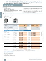
Selection and ordering data<br />
Fully wired and tested contactor assemblies 2) · Size S00 · up to 5.5 kW<br />
AC operation, 50/60 Hz<br />
3RA13 1 . -8XB30-1 . . .<br />
DC operation<br />
1) Coil operating range<br />
at 50 Hz: 0.8 ... 1.1 x U s;<br />
at 60 Hz: 0.85 ... 1.1 x U s.<br />
3RA13 complete units, 3 ... 45 kW<br />
Rated data AC-2 and AC-3 Rated control Screw terminals Weight per<br />
supply voltage U s 1) PU approx.<br />
Operational Ratings of induction Order No.<br />
current I e up to motors at 50 Hz and<br />
415 V 230 V 415 V 500 V 690 V<br />
A kW kW kW kW V kg<br />
7 2-2 3 3.5 4 110 AC 3RA13 15-8XB30-1AF0 0.430<br />
230 AC 3RA13 15-8XB30-1AP0 0.430<br />
9 3 4 4.5 5.5 110 AC 3RA13 16-8XB30-1AF0 0.430<br />
230 AC 3RA13 16-8XB30-1AP0 0.430<br />
12 3 5.5 5.5 5.5 110 AC 3RA13 17-8XB30-1AF0 0.430<br />
230 AC 3RA13 17-8XB30-1AP0 0.430<br />
7 2-2 3 3.5 4 24 DC 3RA13 15-8XB30-1BB4 0.550<br />
9 3 4 4.5 5.5 24 DC 3RA13 16-8XB30-1BB4 0.550<br />
2) The contactors integrated in the contactor assemblies have no<br />
unassigned auxiliary contacts.<br />
Accessories Order No. Page Individual parts Order No. Page<br />
K1 K2<br />
14 Auxiliary switch block, 1 2 Contactors, 3 kW 3RT10 15 3RT10 15 2/12<br />
front<br />
(auxiliary switch block<br />
according to EN 50005<br />
3RH19 11-1.... 2/47 1<br />
1<br />
2<br />
2<br />
Contactors, 4 kW<br />
Contactors, 5.5 kW<br />
3RT10 16<br />
3RT10 17<br />
3RT10 16<br />
3RT10 17<br />
2/12<br />
2/12<br />
must be used)<br />
4 5 6 Installation kit 3RA19 13-2A 2/24<br />
16 Surge suppressors 3RT19 16-1.... 2/51 The installation kit contains:<br />
1) 3RT10 1. contactors with one NC contact in the basic unit are required<br />
for the electrical interlock.<br />
3RA13 Reversing Contactor Assemblies<br />
Mountable accessories (to be ordered separately): The fully wired and tested contactor assembly includes the following<br />
components:<br />
4 Mechanical interlock<br />
5 2 connecting clips for 2 contactors<br />
6 Wiring modules on the top and bottom for connecting<br />
the main current paths, electrical interlock included1) ,<br />
interruptible (NC contact interlock)<br />
2/19<br />
2
2<br />
3RA13 Reversing Contactor Assemblies<br />
3RA13 complete units, 3 ... 45 kW<br />
Fully wired and tested contactor assemblies · Size S0 · up to 11 kW<br />
3RA13 1 . -8XB30-1 . . .<br />
2/20<br />
14<br />
14<br />
15<br />
Rated data AC-2 and AC-3 Rated control Screw terminals Weight per<br />
supply voltage U s 1) PU approx.<br />
Operational Ratings of induction Order No.<br />
current I e up to motors at 50 Hz and<br />
415 V 230 V 415 V 500 V 690 V<br />
A kW kW kW kW V kg<br />
AC operation, 50/60 Hz<br />
12 3 5.5 7.5 7.5 110 AC 3RA13 24-8XB30-1AG2 0.770<br />
230 AC 3RA13 24-8XB30-1AL2 0.770<br />
17 4 7.5 10 11 110 AC 3RA13 25-8XB30-1AG2 0.770<br />
230 AC 3RA13 25-8XB30-1AL2 0.770<br />
25 5.5 11 11 11 110 AC 3RA13 26-8XB30-1AG2 0.770<br />
230 AC 3RA13 26-8XB30-1AL2 0.770<br />
DC operation<br />
1) Coil operating range<br />
at 50 Hz: 0.8 ... 1.1 x U s; at 60 Hz: 0.85 ... 1.1 x U s.<br />
12 3 5.5 7.5 7.5 24 DC 3RA13 24-8XB30-1BB4 1-230<br />
17 4 7.5 10 11 24 DC 3RA13 25-8XB30-1BB4 1-230<br />
25 5.5 11 11 11 24 DC 3RA13 26-8XB30-1BB4 1-230<br />
Mountable accessories (to be ordered separately): The fully wired and tested contactor assembly includes the following<br />
components:<br />
12<br />
16<br />
Accessories Order No. Page Individual parts Order No. Page<br />
4<br />
6<br />
6<br />
1<br />
K1 K2<br />
12 Mechanical interlock, front 3RA19 24-1A 2/23 1 2 Contactors, 5.5 kW 3RT10 24 3RT10 24 2/13<br />
14 Auxiliary switch block, front 3RH19 21-1CA . . 2/47 1 2 Contactors, 7.5 kW 3RT10 25 3RT10 25 2/13<br />
15 Auxiliary switch block, lateral 3RH19 21-1EA . . 2/48 1 2 Contactors, 11 kW 3RT10 26 3RT10 26 2/13<br />
16 Surge suppressors 3RT19 26-1 . . . . 2/51 4 Mechanical interlock,<br />
lateral<br />
3RA19 24-2B 2/23<br />
6 Installation kit 3RA19 23-2A 2/24<br />
The installation kit contains wiring modules on the top and<br />
bottom(they also form the mechanical connection between<br />
the contactors).<br />
2<br />
NSB00460<br />
The connecting<br />
cables are not<br />
shown.
Fully wired and tested contactor assemblies · Size S2 · up to 22 kW<br />
3RA13 3 . -8XB30-1 . . .<br />
14<br />
14<br />
15<br />
12<br />
16<br />
1<br />
4<br />
3RA13 complete units, 3 ... 45 kW<br />
Rated data AC-2 and AC-3 Rated control Screw terminals Weight per<br />
supply voltage U s 1) PU approx.<br />
Operational Ratings of induction Order No.<br />
current I e up to motors at 50 Hz and<br />
500 V 230 V 415 V 500 V 690 V<br />
A kW kW kW kW V kg<br />
AC operation, 50/60 Hz<br />
32 7.5 15 18.5 18.5 110 AC 3RA13 34-8XB30-1AG2 2.300<br />
230 AC 3RA13 34-8XB30-1AL2 2.300<br />
40 11 18.5 22 22 110 AC 3RA13 35-8XB30-1AG2 2.300<br />
230 AC 3RA13 35-8XB30-1AL2 2.300<br />
50 15 22 30 22 110 AC 3RA13 36-8XB30-1AG2 2.300<br />
230 AC 3RA13 36-8XB30-1AL2 2.300<br />
DC operation<br />
1) Coil operating range<br />
at 50 Hz: 0.8 ... 1.1 x U s; at 60 Hz: 0.85 ... 1.1 x U s.<br />
3RA13 Reversing Contactor Assemblies<br />
32 7.5 15 18.5 18.5 24 DC 3RA13 34-8XB30-1BB4 3.450<br />
40 11 18.5 22 22 24 DC 3RA13 35-8XB30-1BB4 3.450<br />
50 15 22 30 22 24 DC 3RA13 36-8XB30-1BB4 3.450<br />
Mountable accessories (to be ordered separately): The fully wired and tested contactor assembly includes the following<br />
components:<br />
5<br />
6<br />
6<br />
NSB00461<br />
2<br />
The connecting<br />
cables are not<br />
shown.<br />
Accessories Order No. Page Individual parts Order No. Page<br />
K1 K2<br />
12 Mechanical interlock, front 3RA19 24-1A 2/23 1 2 Contactors, 15 kW 3RT10 34 3RT10 34 2/13<br />
14 Auxiliary switch block, front 3RH19 21-1CA . . 2/47 1 2 Contactors, 18.5 kW 3RT10 35 3RT10 35 2/13<br />
15 Auxiliary switch block, lateral 3RH19 21-1EA . . 2/47 1 2 Contactors, 22 kW 3RT10 36 3RT10 36 2/13<br />
16 Surge suppressors 3RT19 26-1 . . . . 2/51 4 Mechanical interlock, 3RA19 24-2B 2/23<br />
3RT19 36-1 . . . . lateral<br />
5 6 Installation kit 3RA19 33-2A<br />
The installation kit contains: 2/24<br />
5 2 connecting clips for 2 contactors with a clearance<br />
of 10 mm<br />
6 Wiring modules on the top and bottom for connecting<br />
the main current paths<br />
2/21<br />
2
2<br />
3RA13 Reversing Contactor Assemblies<br />
3RA13 complete units, 3 ... 45 kW<br />
Fully wired and tested contactor assemblies · Size S3 · up to 45 kW<br />
3RA13 4 . -8XB30-1 . . .<br />
1) Coil operating range<br />
at 50 Hz: 0.8 ... 1.1 x U s; at 60 Hz: 0.85 ... 1.1 x U s.<br />
Mountable accessories (to be ordered separately): The fully wired and tested contactor assembly includes the following<br />
components:<br />
2/22<br />
14<br />
14<br />
15<br />
Rated data AC-2 and AC-3 Rated control Screw terminals Weight per<br />
1) supply voltage Us PU approx.<br />
Operational Ratings of induction Order No.<br />
current Ie up to motors at 50 Hz and<br />
500 V 230 V 415 V 500 V 690 V<br />
A kW kW kW kW V kg<br />
AC operation, 50/60 Hz<br />
65 18.5 30 37 45 110 AC 3RA13 44-8XB30-1AG2 4.500<br />
230 AC 3RA13 44-8XB30-1AL2 4.500<br />
80 22 37 45 55 110 AC 3RA13 45-8XB30-1AG2 4.500<br />
230 AC 3RA13 45-8XB30-1AL2 4.500<br />
95 22 45 55 55 110 AC 3RA13 46-8XB30-1AG2 4.500<br />
230 AC 3RA13 46-8XB30-1AL2 4.500<br />
DC operation<br />
65 18.5 30 37 45 24 DC 3RA13 44-8XB30-1BB4 6.500<br />
80 22 37 45 55 24 DC 3RA13 45-8XB30-1BB4 6.500<br />
95 22 45 55 55 24 DC 3RA13 46-8XB30-1BB4 6.500<br />
12<br />
16<br />
1<br />
4<br />
5<br />
6<br />
6<br />
NSB00462<br />
2<br />
The connecting<br />
cables are not<br />
shown.<br />
Accessories Order No. Page Individual parts Order No. Page<br />
K1 K2<br />
12 Mechanical interlock, front 3RA19 24-1A 2/23 1 2 Contactors, 30 kW 3RT10 44 3RT10 44 2/13<br />
14 Auxiliary switch block, front 3RH19 21-1CA . . 2/47 1 2 Contactors, 37 kW 3RT10 45 3RT10 45 2/13<br />
15 Auxiliary switch block, lateral 3RH19 21-1EA . . 2/47 1 2 Contactors, 45 kW 3RT10 46 3RT10 46 2/13<br />
16 Surge suppressors 3RT19 26-1 . . . . 2/51 4 Mechanical interlock, 3RA19 24-2B 2/23<br />
3RT19 36-1 . . . . lateral<br />
5 6 Installation kit 3RA19 43-2A 2/24<br />
The installation kit contains:<br />
5 2 connecting clips for 2 contactors with a clearance<br />
of 10 mm<br />
6 Wiring modules on the top and bottom for connecting<br />
the main current paths
Selection and ordering data<br />
Mechanical interlocks<br />
3RA19 24-1A mounted<br />
onto 2 contactors<br />
3RA19 54-2A<br />
3RA19 54-2C<br />
Base plates<br />
Components for customer assembly<br />
For Size Version Order No. Weight per<br />
contactors PU approx.<br />
Type kg<br />
3RT10 2 S0 For lateral mounting1) 3RA19 24-2B 0.060<br />
3RT10 3 S2 Each with one auxiliary contact (1 NC contact)<br />
3RT10 4 S3 per contactor (can only be used to connect<br />
3RT13 2 contactors which are not more than 1 size<br />
3RT13 3 larger or smaller. The mounting depth of the<br />
3RT13 4<br />
3RT15 2<br />
3RT15 3<br />
smaller contactor has to be adapted.)<br />
3RT10 2 S0 For mounting to the front2) 3RA19 24-1A 0.050<br />
3RT10 3 S2 Onto contactors with sizes S0 to S3<br />
3RT10 4 S3 (for contactors of the same size)<br />
3RT13 2 S0 Note:<br />
3RT15 2 Size S0: Wiring modules must be mounted first<br />
Sizes S2 and S3: Use 3RA19 32-2C<br />
mechanical connectors<br />
1) Can also be used for 4-pole contactors with sizes S2 and S3.<br />
2) Can also be used for size S0 4-pole contactors.<br />
3RA13 Reversing Contactor Assemblies<br />
3RT1 . 5 S6 For lateral mounting 3RA19 54-2A 0.050<br />
to S10 Without auxiliary contacts; size S6, S10 and<br />
3RT1 . 7 S12 S12 contactors can be interlocked with each other<br />
as required; no adaptation of mounting depth<br />
is necessary. Contactor clearance 10 mm.<br />
3RT10 4 . -A S3 Adapters, laterally mountable 3RA19 54-2C 0.050<br />
with with For mechanical interlocking of contactor S3<br />
3RT10 5 S6 (only for AC operation) with contactor S6 using<br />
3RA19 54-2A locking device (must be ordered<br />
separately) incl. connecting clips.<br />
3RT10 5 S6 For customer assembly of reversing 3RA19 52-2A 1.300<br />
3RT1 . 6 S10 contactor assemblies 3RA19 62-2A 2.100<br />
3RT1 . 7 S12 3RA19 72-2A 2.300<br />
2/23<br />
2
2<br />
3RA13 Reversing Contactor Assemblies<br />
Components for customer assembly<br />
2/24<br />
For Size Version Order No. Weight per<br />
contactors PU approx.<br />
Type kg<br />
Installation kits for making 3-pole contactor assemblies<br />
3RA19 13-2A<br />
3RA19 23-2A<br />
3RA19 33-2A<br />
3RA19 43-2A<br />
3RT10 1 S00 The installation kit contains: 3RA19 13-2A 0.040<br />
mechanical interlock;<br />
2 connecting clips for 2 contactors;<br />
wiring modules on the top and bottom<br />
3RT10 2 S0 The installation kit contains: 3RA19 23-2A 0.060<br />
wiring modules on the top and bottom<br />
3RT10 3 S2 The installation kit contains: 3RA19 33-2A 0.120<br />
2 connecting clips for 2 contactors;<br />
wiring modules on the top and bottom<br />
3RT10 4 S3 The installation kit contains: 3RA19 43-2A 0.300<br />
2 connecting clips for 2 contactors;<br />
wiring modules on the top and bottom<br />
3RT10 5 S6 The installation kit contains: 3RA19 53-2A 1.300<br />
wiring modules on the top and bottom<br />
(for connection with box terminal)<br />
3RT10 5 S6 The installation kit contains: 3RA19 53-2M 0.900<br />
3RT1. 6 S10 wiring modules on the top and bottom 3RA19 63-2A 2.400<br />
3RT1. 7 S12 (for connection without box terminal) 3RA19 73-2A 3.000
Wiring modules, single<br />
3RA19 53-3D<br />
3RA19 53-3P<br />
For Size Contactor Version Order No. Weight per<br />
contactors clearance PU approx.<br />
Type mm kg<br />
3RT10 1 S00-S00 0 top (in-phase) 3RA19 13-3D 0.015<br />
bottom (with phase reversal) 3RA19 13-3E 0.015<br />
3RT10 2 S0-S0 0 and10 top (in-phase) 3RA19 23-3D 0.020<br />
and bottom (with phase reversal) 3RA19 23-3E 0.020<br />
S0-S0<br />
3RT10 3 S2-S2 10 top (in-phase) 3RA19 33-3D 0.065<br />
bottom (with phase reversal) 3RA19 33-3E 0.065<br />
3RT10 4 S3-S3 10 top (in-phase) 3RA19 43-3D 0.160<br />
bottom (with phase reversal) 3RA19 43-3E 0.160<br />
3RT10 5 S6-S6 10 top (in-phase, for connection 3RA19 53-3D 0.620<br />
with box terminal)<br />
top (with phase reversal, for 3RA19 53-3P 0.440<br />
connection without box terminal)<br />
For Size Contactor Interlocking Version Order No. Weight per<br />
contactors clearance PU approx.<br />
Type mm kg<br />
Mechanical connectors 1 pack = 10 sets for 10 assemblies<br />
3RA19 12-2H<br />
3RA19 22-2C<br />
3RA19 32-2C<br />
3RA19 32-2D<br />
3RA19 32-2G<br />
3RA19 42-2G<br />
3RT1. 1 1) S00-S00 0 laterally for 3- and 4-pole 3RA19 12-2H 0.010<br />
mountable contactors<br />
3RT1. 2 S0-S0 0 mountable for 3- and 4-pole 3RA19 22-2C 0.025<br />
10 2) on front contactors<br />
laterally 3RT19 22-2D 0.110<br />
mountable<br />
3RT1. 3 S2-S2 0 mountable for 3-pole 3RA19 32-2C 0.010<br />
3RT1. 4 S3-S3 on front contactors<br />
3RT1. 3 S2-S2 10 laterally for 3-pole 3RA19 32-2D 0.010<br />
3RT1. 4 S3-S3 mountable contactors<br />
3RT1. 5 S6-S6<br />
3RT1. 3 S2-S2 10 laterally for 4-pole 3RA19 32-2G 0.010<br />
mountable contactors<br />
3RT1. 4 S3-S3 10 laterally for 4-pole 3RA19 42-2G 0.010<br />
mountable contactors<br />
1) This pack contains 10 additional interlocks.<br />
2) The connector function can be fulfilled with the wiring modules for size<br />
S0, a contactor clearance of 10 mm and a lateral interlock.<br />
3RA13 Reversing Contactor Assemblies<br />
Components for customer assembly<br />
2/25<br />
2
2<br />
3RA14 Contactor Assemblies for Wye-Delta Starting<br />
3RA14 complete units, 3 ... 75 kW<br />
Overview<br />
These 3RA14 contactor assemblies for wye-delta starting are<br />
designed for standard applications.<br />
Note:<br />
Contactor assemblies for wye-delta starting in special<br />
applications such as very heavy starting or wye-delta starting of<br />
special motors must be customized. Help with designing such<br />
special applications is available from Technical Assistance.<br />
The 3RA14 contactor assemblies for wye-delta starting can be<br />
ordered as follows:<br />
Sizes S00 to S3:<br />
• Fully wired and tested, with electrical interlock, dead interval<br />
of up to 10 s on reversing (size S00 with electrical and<br />
mechanical interlocks)<br />
Sizes S00 to S12:<br />
• As individual parts for customer assembly.<br />
2/26<br />
A dead interval of 50 ms on reversing is already integrated in<br />
the time relay function.<br />
There is also a range of accessories (auxiliary switch blocks,<br />
surge suppressors, etc.) that must be ordered separately.<br />
For overload relays for motor protection, see “Protection<br />
Equipment: Overload Relays -> 3RB2 Solid-State Overload<br />
Relays”.<br />
The 3RA14 contactor assemblies have screw terminals and are<br />
suitable for screwing or snapping onto 35 mm standard<br />
mounting rails.<br />
Fully wired and tested 3RA14 contactor assemblies have one<br />
unassigned NO contact which is mounted onto the front of the<br />
delta contactor.<br />
A solid-state time-delay auxiliary switch block is snapped onto<br />
the front of the complete contactor assemblies, size S00 up to<br />
7.5 kW, while a timing relay is mounted onto the side of<br />
sizes S0 to S3, 11 kW to 75 kW.<br />
Rated data Size Accessories for<br />
at AC 50 Hz 415 V customer assembly<br />
Rating Operational Motor Line/delta Star Order No. Timing relay Installation kit A,<br />
current Ie current contactor contactor complete for double infeed<br />
kW A A<br />
5.5 12 9.5 ... 13.8 S00-S00-S00 3RT10 15 3RT10 15 3RA14 15-8XB31-1 . . . 3RT19 16-2G . 51 —<br />
7.5 17 12.1 ... 17 3RT10 17 3RA14 16-8XB31-1 . . . 3RP15 74-1N . 30<br />
11 25 19 ... 25 S0-S0-S0 3RT10 24 3RT10 24 3RA14 23-8XC21-1 . . . 3RP15 74-1N . 30 —<br />
15 32 24.1 ... 34 3RT10 26 3RA14 25-8XC21-1 . . .<br />
18.5 40 34.5 ... 40<br />
22 50 31 ... 43 S2-S2-S0 3RT10 34 3RT10 26 3RA14 34-8XC21-1 . . . 3RP15 74-1N . 30 3RA19 33-2C 3)<br />
30 50 48.3 ... 65 3RT10 35 —<br />
37 80 62.1 ... 77.8 S2-S2-S2 3RT10 34 3RA14 35-8XC21-1 . . . 3RA19 33-2B 3)<br />
45 86 69 ... 86 3RT10 36 3RA14 36-8XC21-1 . . .<br />
55 115 77.6 ... 108.6 S3-S3-S2 3RT10 44 3RT10 35 3RA14 44-8XC21-1 . . . 3RP15 74-1N . 30 3RA19 43-2C 3)<br />
75 150 120.7... 150 3RT10 45 3RT10 36 3RA14 45-8XC21-1 . . .<br />
90 160 86 ... 160 S6-S6-S3 3RT10 54 3RT10 44 — 3RP15 74-1N . 30 —<br />
110 195 86 ... 195<br />
132 230 86 ... 230 3RT10 55 3RT10 45<br />
160 280 86 ... 280 3RT10 56 3RT10 46<br />
200 350 95 ... 350 S10-S10-S6 3RT10 64 3RT10 54 — 3RP15 74-1N . 30 —<br />
250 430 95 ... 430 3RT10 65 3RT10 55<br />
315 540 277 ... 540 S12-S12-S10 3RT10 75 3RT10 64 — 3RP15 74-1N . 30 —<br />
355 610 277 ... 610<br />
400 690 277 ... 690 3RT10 65<br />
500 850 277 ... 850 3RT10 76 3RT10 66<br />
1) Installation kit contains mechanical interlock, 3 connecting clips; wiring<br />
modules on the top (connection between line and delta contactor) and<br />
on the bottom (connection between delta and star contactor); star<br />
jumper.<br />
2) The installation kit contains 5 connecting clips; wiring modules on the<br />
top (connection between line and delta contactor) and on the bottom<br />
(connection between delta and star contactor); star jumper.<br />
3) Installation kit contains wiring module on the bottom (connection<br />
between delta and star contactor) and star jumper.<br />
4) Wiring module on top from reversing contactor assembly (note conductor<br />
cross-sections).
Components for customer assembly<br />
Installation kits with wiring modules and, if necessary,<br />
mechanical connectors are available for contactor assemblies<br />
for wye-delta starting. Contactors, overload relays, wye-delta<br />
timing relays, auxiliary switches for electrical interlock – if<br />
required also feeder terminals, mechanical interlocks<br />
(exception: In the case of the installation kit for size S00<br />
contactor assemblies the mechanical interlock between the<br />
delta contactor and the star contactor is included in the kit) and<br />
base plates – must be ordered separately.<br />
The wiring kits for sizes S00 and S0 contain the top and bottom<br />
main conducting path connections between the line and delta<br />
contactors (top) and between the delta and star contactors<br />
(bottom).<br />
3RA14 Contactor Assemblies for Wye-Delta Starting<br />
3RA14 complete units, 3 ... 75 kW<br />
In the case of sizes S2 to S12 only the bottom main conducting<br />
path connection between the delta and star contactors is<br />
included in the wiring module, owing to the larger conductor<br />
cross-section at the infeed.<br />
Motor protection<br />
Overload relays or thermistor motor protection tripping units<br />
can be used for overload protection.<br />
The overload relay can be either mounted onto the line<br />
contactor or separately fitted. It must be set to 0.58 times the<br />
rated motor current.<br />
Overload relay, thermal Overload relay, solid-state<br />
(trip class CLASS 10) (trip class CLASS 10)<br />
Installation kit B,<br />
for single infeed<br />
Star jumper Base plates Setting range Order No. Setting range Order No.<br />
A A<br />
3RA19 13-2B 1) 3RT19 16-4BA31 — 5.5 ... 8 3RU11 16-1HB0 3 ... 12 3RB20 16-1SB0<br />
7 ... 10 3RU11 16-1JB0<br />
3RA19 23-2B2) 3RT19 26-4BA31 — 11 ... 16 3RU11 26-4AB0 6 ... 25 3RB20 26-1QB0<br />
14 .. 20 3RU11 26-4BB0<br />
20 ... 25 3RU11 26-4DB0<br />
3RV19 35-1A 3RT19 26-4BA31 3RA19 32-2E 18 ... 25 3RU11 36-4DB0 12.5 ... 50 3RB20 36-1UB0<br />
28 ... 40 3RU11 36-4FB0<br />
3RT19 36-4BA31 3RA19 32-2F 36 ... 45 3RU11 36-4GB0<br />
40 ... 50 3RU11 36-4HB0<br />
— 3RT19 36-4BA31 3RA19 42-2E 45 ... 63 3RU11 46-4JB0 25 ...100 3RB20 46-1EB0<br />
70 ... 90 3RU11 46-4LB0<br />
3RA19 53-3D 4) 3RT19 46-4BA31 3RA19 52-2E — — 50 ...200 3RB20 56-1FC2<br />
— 3RT19 56-4BA31 3RA19 62-2E — — 55 ...250 3RB20 66-1GC2<br />
— 3RT19 66-4BA31 3RA19 72-2E — — 160 ...630 3RB20 66-1MC2<br />
2/27<br />
2
2<br />
3RA14 Contactor Assemblies for Wye-Delta Starting<br />
3RA14 complete units, 3 ... 75 kW<br />
Selection and ordering data<br />
Fully wired and tested contactor assemblies · Size S00-S00-S00 · up to 7.5 kW<br />
3RA14 1 . -8XB31-1 . . .<br />
2/28<br />
14<br />
14 14<br />
14<br />
Rated data AC-3 Rated control Screw terminals Weight per<br />
supply voltage U s 1) PU approx.<br />
Operational Ratings of induction Order No.<br />
current I e up to motors at 50 Hz and<br />
415 V 230 V 415 V 500 V 690 V<br />
A kW kW kW kW V kg<br />
AC operation, 50/60 Hz<br />
12 3.3 5.5 7-2 9-2 230 AC 3RA14 15-8XB31-1AP0 0.950<br />
17 4.7 7.5 10.3 9-2 230 AC 3RA14 16-8XB31-1AP0 0.990<br />
DC operation<br />
1)Coil operating range<br />
at 50 Hz: 0.8 ... 1.1 x U s; at 60 Hz: 0.85 ... 1.1 x U s.<br />
12 3.3 5.5 7-2 9-2 24 DC 3RA14 15-8XB31-1BB4 1.120<br />
17 4.7 7.5 10.3 9-2 24 DC 3RA14 16-8XB31-1BB4 1.120<br />
Mountable accessories (to be ordered separately): The fully wired and tested contactor assembly includes the following<br />
components:<br />
16<br />
17<br />
7<br />
Accessories Order No. Page Individual parts Order No. Page<br />
9<br />
4<br />
1<br />
6<br />
5<br />
2<br />
6<br />
6<br />
3<br />
NSB00463<br />
K1 1) K3 2) K2 2)<br />
14 Auxiliary switch block, front 3RH19 11-1 . . . . 2/47 1 2 3 Contactors, 5.5 kW 3RT10 15 3RT10 15 3RT10 15 2/12<br />
16 Surge suppressors 3RT19 16-1 . . . . 2/51 1 2 3 Contactors, 7.5 kW 3RT10 17 3RT10 17 3RT10 15 2/12<br />
17 3-phase feeder terminals 3RA19 13-3K 2/33 7 Solid-state time-delay<br />
auxiliary switch block,<br />
front 3RT19 16-2G . 51 2/49<br />
9 Auxiliary switch block<br />
with 1 unassigned<br />
NO contact 3RH19 11-1BA10 2/47<br />
4 5 6 Installation kit 3RA19 13-2B 2/33<br />
The installation kit contains:<br />
4 Mechanical interlock<br />
5 3 connecting clips<br />
6 Wiring modules on the top and bottom for connecting the main<br />
and control conducting paths<br />
1) Use version with 1 NO.<br />
2) Use version with 1 NC.<br />
The connecting<br />
cables are not<br />
shown.
Fully wired and tested contactor assemblies · Size S0-S0-S0 · up to 18.5 kW<br />
3RA14 2 . -8XC21-1 . . .<br />
1) Coil operating range at 50 Hz:<br />
0.8 ... 1.1 x U s ; at 60 Hz: 0.85 ... 1.1 x U s.<br />
Mountable accessories (to be ordered separately): The fully wired and tested contactor assembly includes the following<br />
components:<br />
17<br />
12<br />
18<br />
4<br />
16<br />
15<br />
7<br />
10<br />
9<br />
1<br />
10<br />
10<br />
3RA14 complete units, 3 ... 75 kW<br />
Rated data AC-3 Rated control Screw terminals Weight per<br />
1) supply voltage Us PU approx.<br />
Operational Ratings of induction Order No.<br />
current Ie up to motors at 50 Hz and<br />
415 V 230 V 415 V 500 V 690 V<br />
A kW kW kW kW V kg<br />
AC operation, 50/60 Hz<br />
25 7.1 11 15.6 19 230 AC 3RA14 23-8XC21-1AL2 1.800<br />
32 / 40<br />
DC operation<br />
11.4 15 / 18.5 19 19 230 AC 3RA14 25-8XC21-1AL2 1.800<br />
25 7.1 11 15.6 19 24 DC 3RA14 23-8XC21-1BB4 2.450<br />
32 / 40 11.4 15 / 18.5 19 19 24 DC 3RA14 25-8XC21-1BB4 2.450<br />
1) Generally possible. If a solid-state time-delay auxiliary switch block is<br />
mounted onto the front of K3, a standard auxiliary switch block can only<br />
be mounted onto the side.<br />
2) 17 and 18 can only be mounted with contactors with screw terminal<br />
(coil).<br />
3RA14 Contactor Assemblies for Wye-Delta Starting<br />
6<br />
2<br />
6<br />
6<br />
8<br />
5<br />
3<br />
NSB0_00464a<br />
19<br />
19<br />
The connecting<br />
cables are not<br />
shown.<br />
Accessories Order No. Page Individual parts Order No. Page<br />
K1 K3 K2<br />
1 Mechanical interlock, lateral 3RA19 24-2B 2/23 1 2 3 Contactors, 11 kW 3RT10 24 3RT10 24 3RT10 24 2/13<br />
7 Solid-state time-delay 1 2 3 Contactors, 15/18.5 kW 3RT10 26 3RT10 26 3RT10 24 2/13<br />
auxiliary switch block, front1) 3RT19 26-2G . . . 2/49<br />
12 Mechanical interlock, front 3RA19 24-1A 2/23 8 Timing relay, lateral 3RP15 74-1N . 30 4)<br />
15 Auxiliary switch block, lateral 3RH19 21-1EA . . 2/48 9 Auxiliary switch block with<br />
1 unassigned NO contact 3RH19 21-1CA10 2/47<br />
16 Surge suppressors 3RT19 26-1 . . . . 2/51 10 Auxiliary switch block<br />
for local control<br />
17 3-phase feeder terminal2) 3RV19 15-5A 2/33<br />
2 units 3RH19 21-1CA01<br />
18 3-phase busbar2) 3 units 3RH19 21-1CA10<br />
3RT19 26-4CC20 2/33<br />
2/47<br />
19 Push-in lug3) for timing relay 5 6 Installation kit 3RA19 23-2B 2/33<br />
screw mounting 3RP19 03 4)<br />
The installation kit contains:<br />
5 Connecting clips<br />
6 Wiring modules on the top and bottom for connecting the main<br />
and control conducting paths<br />
3) Not part of the scope of supply of the preassembled contactor<br />
assemblies; can be ordered as an accessory.<br />
4) See Monitoring and Control Devices: 3RP, 7PV timing relays -> 3RP15<br />
timing relays in 22.5 mm industrial enclosure.<br />
2/29<br />
2
2<br />
3RA14 Contactor Assemblies for Wye-Delta Starting<br />
3RA14 complete units, 3 ... 75 kW<br />
Fully wired and tested contactor assemblies · Size S2-S2-S0 · up to 30 kW<br />
3RA14 34-8XC21-1 . . .<br />
Mountable accessories (to be ordered separately): The fully wired and tested contactor assembly includes the following<br />
components:<br />
2/30<br />
17<br />
4<br />
18<br />
Rated data AC-3 Rated control Screw terminals Weight per<br />
1) supply voltage Us PU approx.<br />
Operational Ratings of induction Order No.<br />
current Ie up to motors at 50 Hz and<br />
415 V 230 V 415 V 500 V 690 V<br />
A kW kW kW kW V kg<br />
AC operation, 50/60 Hz<br />
50 / 65 19.6 22 / 30 35 34 230 AC 3RA14 34-8XC21-1AL2 3.100<br />
DC operation<br />
50 / 65 19.6 22 / 30 35 34 24 DC 3RA14 34-8XC21-1BB4 4.500<br />
1) Coil operating range at 50 Hz: 0.8 ... 1.1 x U s ; at 60 Hz: 0.85 ... 1.1 x U s .<br />
Accessories Order No. Page<br />
4 Mechanical interlock, lateral<br />
Depth compensation required<br />
K3: 1.5 mm; K2: 0 mm1) 3RA19 24-2B 2/23<br />
7 Solid-state time-delay<br />
auxiliary switch block, front2) 3RT19 26-2G . . . 2/49<br />
15 Auxiliary switch block, lateral 3RH19 21-1EA . . 2/48<br />
16 Surge suppressors 3RT19 26-1 . . . .<br />
3RT19 36-1 . . . .<br />
2/51<br />
17 3-phase feeder terminal 3RV19 35-5A 2/33<br />
18 3-phase busbars 3RV19 35-1A 2/33<br />
19 Push-in lug3) for timing relay<br />
screw mounting 3RP19 03 4)<br />
1) Use the 3RA19 32-2B base plate for this configuration.<br />
2) Generally possible. If a solid-state time-delay auxiliary switch block is<br />
mounted onto the front of K3, a standard auxiliary switch block can only<br />
be mounted onto the side.<br />
16<br />
15<br />
7<br />
10<br />
9<br />
10<br />
1<br />
10<br />
6<br />
2<br />
6<br />
8<br />
3<br />
NSB0_00465b<br />
11<br />
19<br />
The connecting<br />
cables are not<br />
shown.<br />
Individual parts Order No. Page<br />
K1 K3 K2<br />
1 2 3 Contactors, 22/30 kW 3RT10 34 3RT10 34 3RT10 26 2/13<br />
8 Timing relay, lateral 3RP15 74-1N . 30 4)<br />
9 Auxiliary switch block with 3RH19 21-1CA10<br />
1 unassigned NO contact<br />
2/47<br />
10 Auxiliary switch block for<br />
local control<br />
2 units 3RH19 21-1CA01 2/47<br />
3 units 3RH19 21-1CA10<br />
11 Base plate 3RA19 32-2E 2/33<br />
6 Installation kit 3RA19 33-2C 2/33<br />
The installation kit contains the star jumper on the top and the wiring<br />
module on the bottom for connecting the main current paths.<br />
3) Not part of the scope of supply of the preassembled contactor<br />
assemblies; can be ordered as an accessory.<br />
4) See Monitoring and Control Devices: 3RP, 7PV timing relays -> 3RP15<br />
timing relays in 22.5 mm industrial enclosure.
Fully wired and tested contactor assemblies · Size S2-S2-S2 · up to 45 kW<br />
3RA14 3 . -8XC21-1 . . .<br />
Mountable accessories (to be ordered separately): The fully wired and tested contactor assembly includes the following<br />
components:<br />
1<br />
2<br />
6<br />
17<br />
16<br />
3<br />
12<br />
18<br />
4<br />
Rated data AC-3 Rated control Screw terminals Weight per<br />
1) supply voltage Us PU approx.<br />
Operational Ratings of induction Order No.<br />
current Ie up to motors at 50 Hz and<br />
415 V 230 V 415 V 500 V 690 V<br />
A kW kW kW kW V kg<br />
AC operation, 50/60 Hz<br />
80 25 37 51 63 230 AC 3RA14 35-8XC21-1AL2 3.700<br />
86<br />
DC operation<br />
27 45 55 63 230 AC 3RA14 36-8XC21-1AL2 3.700<br />
80 25 37 51 63 24 DC 3RA14 35-8XC21-1BB4 5.500<br />
86 27 45 55 63 24 DC 3RA14 36-8XC21-1BB4 5.500<br />
1) Coil operating range at 50 Hz: 0.8 ... 1.1 x U s; at 60 Hz: 0.85 ... 1.1 x U s.<br />
Accessories Order No. Page<br />
4 Mechanical interlock, lateral 3RA19 24-2B 2/23<br />
7 Solid-state time-delay<br />
auxiliary switch block, front1) 3RT19 26-2G . . . 2/49<br />
12 Mechanical interlock, front 3RA19 24-1A 2/23<br />
15 Auxiliary switch block, lateral 3RH19 21-1EA . . 2/48<br />
16 Surge suppressors 3RT19 26-1 . . . .<br />
3RT19 36-1 . . . .<br />
2/51<br />
17 3-phase feeder terminals 3RV19 35-5A 2/33<br />
18 3-phase busbars 3RV19 35-1A 2/33<br />
19 Push-in lug2) for timing relay<br />
screw mounting 3RP19 03 3)<br />
1) Generally possible. If a solid-state time-delay auxiliary switch block is<br />
mounted onto the front of K3, a standard auxiliary switch block can only<br />
be mounted onto the side.<br />
3RA14 Contactor Assemblies for Wye-Delta Starting<br />
15<br />
7<br />
10<br />
9<br />
10<br />
10<br />
3RA14 complete units, 3 ... 75 kW<br />
6<br />
8<br />
NSB0_00466a<br />
11<br />
19<br />
The connecting<br />
cables are not<br />
shown.<br />
Individual parts Order No. Page<br />
K1 K3 K2<br />
1 2 3 Contactors, 37 kW 3RT10 35 3RT10 35 3RT10 34 2/13<br />
1 2 3 Contactors, 45 kW 3RT10 36 3RT10 36 3RT10 34 2/13<br />
8 Timing relay, lateral 3RP15 74-1N . 30 3)<br />
9 Auxiliary switch block with<br />
1 unassigned NO contact 3RH19 21-1CA10 2/47<br />
10 Auxiliary switch block for<br />
local control<br />
2 units 3RH19 21-1CA01<br />
3 units 3RH19 21-1CA10 2/47<br />
11 Base plate 3RA19 32-2F 2/33<br />
6 Installation kit 3RA19 33-2B 2/33<br />
The installation kit contains the star jumper on the top and the wiring<br />
module on the bottom for connecting the main current paths.<br />
2) Not part of the scope of supply of the preassembled contactor<br />
assemblies; can be ordered as an accessory.<br />
3) See Monitoring and Control Devices: 3RP, 7PV timing relays -> 3RP15<br />
timing relays in 22.5 mm industrial enclosure.<br />
2/31<br />
2
2<br />
3RA14 Contactor Assemblies for Wye-Delta Starting<br />
3RA14 complete units, 3 ... 75 kW<br />
Fully wired and tested contactor assemblies · Size S2-S3-S2 · up to 75 kW<br />
Mountable accessories (to be ordered separately): The fully wired and tested contactor assembly includes the following<br />
components:<br />
1<br />
2<br />
6<br />
2/32<br />
4<br />
16<br />
15<br />
7<br />
Rated data AC-3 Rated control Screw terminals Weight per<br />
1) supply voltage Us PU approx.<br />
Operational Ratings of induction Order No.<br />
current Ie up to motors at 50 Hz and<br />
415 V 230 V 415 V 500 V 690 V<br />
A kW kW kW kW V kg<br />
AC operation, 50/60 Hz<br />
115 37 55 81 93 230 AC 3RA14 44-8XC21-1AL2 6.000<br />
150<br />
DC operation<br />
47 75 103 110 230 AC 3RA14 45-8XC21-1AL2 6.000<br />
115 37 55 81 93 24 DC 3RA14 44-8XC21-1BB4 8.600<br />
150 47 75 103 110 24 DC 3RA14 45-8XC21-1BB4 8.600<br />
3RA14 4 . -8XC21-1 . . .<br />
1) Coil operating range at 50 Hz: 0.8 ... 1.1 x Us; at 60 Hz: 0.85 ... 1.1 x Us. Accessories Order No. Page<br />
4 Mechanical interlock, lateral<br />
Depth compensation required<br />
K3: 0 mm; K2: 27.5 mm<br />
3RA19 24-2B 2/23<br />
1)<br />
7 Solid-state time-delay<br />
auxiliary switch block, front2) 3RT19 26-2G . . . 2/49<br />
15 Auxiliary switch block, lateral 3RH19 21-1EA . . 2/48<br />
16 Surge suppressors 3RT19 . 6-1 . . . . 2/51<br />
19 Push-in lug3) for timing relay<br />
screw mounting 3RP19 03 4)<br />
20 1-phase feeder terminal 3RA19 43-3L 2/33<br />
1) Use the 3RA19 42-2B base plate for this configuration.<br />
2) Generally possible. If a solid-state time-delay auxiliary switch block is<br />
mounted onto the front of K3, a standard auxiliary switch block can only<br />
be mounted onto the side.<br />
20<br />
10<br />
9<br />
10 10<br />
6<br />
3<br />
8<br />
NSB0_00467d<br />
11<br />
19<br />
The connecting<br />
cables are not<br />
shown.<br />
Individual parts Order No. Page<br />
K1 K3 K2<br />
1 2 3 Contactors, 55 kW 3RT10 44 3RT10 44 3RT10 35 2/13<br />
1 2 3 Contactors, 75 kW 3RT10 45 3RT10 45 3RT10 36 2/13<br />
8 Timing relay, lateral 3RP15 74-1N . 30 4)<br />
9 Auxiliary switch block with<br />
1 unassigned NO contact 3RH19 21-1CA10 2/47<br />
10 Auxiliary switch block for<br />
local control<br />
2 units 3RH19 21-1CA01<br />
3 units 3RH19 21-1CA10 2/47<br />
11 Base plate 3RA19 42-2E 2/33<br />
6 Installation kit 3RA19 43-2C 2/33<br />
The installation kit contains the star jumper on the top and the wiring<br />
module on the bottom for connecting the main current paths.<br />
3) Not part of the scope of supply of the preassembled contactor<br />
assemblies; can be ordered as an accessory.<br />
4) See Monitoring and Control Devices: 3RP, 7PV timing relays -> 3RP15<br />
timing relays in 22.5 mm industrial enclosure.
Selection and ordering data<br />
Installation kits<br />
3RA19 53-2B<br />
3RA19 53-2N,<br />
3RA19 63-2B,<br />
3RA19 73-2B<br />
Components for customer assembly<br />
Version Size Order No. Weight per<br />
PU approx.<br />
Type kg<br />
The installation kit contains:<br />
mechanical interlock;<br />
3 connecting clips<br />
star jumper,<br />
wiring modules on the top and bottom<br />
S00-S00-S00 3RA19 13-2B 0.050<br />
The installation kit contains:<br />
5 connecting clips star jumper,<br />
wiring modules on the top and bottom<br />
S0-S0-S0 3RA19 23-2B 0.060<br />
The installation kit contains: S2-S2-S0 3RA19 33-2C 0.060<br />
star jumper, S2-S2-S2 3RA19 33-2B 0.070<br />
wiring module on the bottom S3-S3-S2 3RA19 43-2C 0.140<br />
(Wiring module on the top is not included S3-S3-S3 3RA19 43-2B 0.160<br />
in the scope of supply. A double infeed<br />
between the line contactor and the<br />
delta contactor is recommended.)<br />
S6-S6-S6 3RA19 53-2B 0.850<br />
S6-S6-S6 3RA19 53-2N 0.600<br />
S10-S10-S10 3RA19 63-2B 1.800<br />
S12-S12-S12 3RA19 73-2B 2-200<br />
1-phase feeder terminals<br />
Conductor cross-section: 95 mm2 3-phase feeder terminals<br />
Feeder terminal block for the line contactor<br />
for large conductor cross-sections<br />
S3 3RA19 43-3L 0-280<br />
Conductor cross-section: 6 mm2 S00 3RA19 13-3K 0.020<br />
Conductor cross-section: 25 mm2 S0 3RV19 15-5A 0.040<br />
Conductor cross-section: 50 mm2 3-phase busbars<br />
Bridging phase-by-phase of all input terminals of<br />
S2 3RV19 35-5A 0.110<br />
The line contactor (K1) and S0 3RT19 26-4CC20 0.030<br />
The delta contactor (K3)<br />
Links for paralleling, 3-pole (star jumpers)<br />
S2 3RV19 35-1A 0.150<br />
Without connection terminal S00 3RT19 16-4BA31 0.010<br />
(the links for paralleling can be S0 3RT19 26-4BA31 0.010<br />
reduced by one pole) S2 3RT19 36-4BA31 0.020<br />
S3 3RT19 46-4BA31 0.030<br />
S61) 3RT19 56-4BA31 0.160<br />
S10, S121) 3RT19 26-4BA31<br />
Base plates<br />
For customer assembly of contactor assemblies<br />
for wye-delta starting with a laterally mounted<br />
timing relay<br />
3RT19 66-4BA31 0.500<br />
Side-by-side mounting S2, S2, S0 3RA19 32-2E 0.450<br />
10 mm distance between K3 and K2 S2, S2, S2 3RA19 32-2F 0.480<br />
Side-by-side mounting S3, S3, S2 3RA19 42-2E 0.870<br />
10 mm distance between K1, K3 and K2 S6, S6, S6 3RA19 52-2F 1.950<br />
S10, S10, S10 3RA19 62-2F 3.400<br />
S12, S12, S12 3RA19 72-2F 3.700<br />
For customer assembly of contactor assemblies S2, S2, S0 3RA19 32-2B 0.450<br />
for wye-delta starting with a front-mounted S2, S2, S2 3RA19 32-2B 0.450<br />
timing relay, 10 mm distance between<br />
K1, K3 and K2<br />
S3, S3, S2 3RA19 42-2B 0.700<br />
1) The 3RT19 56-4EA1 (S6) or 3RT19 66-4EA1 (S10, S12) cover can be used<br />
for touch protection.<br />
3RA14 Contactor Assemblies for Wye-Delta Starting<br />
2/33<br />
2
2<br />
3RT14 Contactors for Switching Resistive Loads (AC-1)<br />
3-pole, 140 ... 690 A<br />
Overview<br />
AC and DC operation (size S3)<br />
UC operation (AC/DC) (sizes S6 to S12)<br />
IEC 60947, EN 60947 (VDE 0660)<br />
The contactors are suitable for use in any climate. They are<br />
finger-safe according to EN 50274.<br />
3RT14 contactors are used for switching resistive loads (AC-1) or<br />
as contactors, for example, for variable-speed operating<br />
mechanisms that normally only have to carry the current.<br />
Selection and ordering data<br />
2/34<br />
The accessories for the 3RT10 contactors can also be used here.<br />
For more detailed descriptions about the sizes S3 to S12,<br />
see 3RT10 Contactors, 3-pole, 3 to 250 kW.<br />
Size Rated data AC-1, Tu: 40 °C Rated control Screw terminals Weight per<br />
supply voltage PU approx.<br />
Operational Ratings of AC loads Us Order No.<br />
current Ie up to (p.f. = 0.95) at<br />
690 V 230 V 400 V 500 V 690 V<br />
A kW kW kW kW V kg<br />
For screw and snap-on mounting onto 35 mm and 75 mm standard mounting rail<br />
AC operation<br />
S3 140 53 92 115 159 24 AC, 50/60 Hz 3RT14 46-1AC20 1.850<br />
110 AC, 50/60 Hz 3RT14 46-1AG00 1.850<br />
230 AC, 50/60 Hz 3RT14 46-1AL00 1.850<br />
400 AC, 50 Hz 3RT14 46-1AV00 1.850<br />
DC operation · DC solenoid system<br />
S3 140 53 92 115 159 24 DC 3RT14 46-1BB40 2.800<br />
110 DC 3RT14 46-1BF40 2.800<br />
220 DC 3RT14 46-1BM40 2.800<br />
3RT14 46-1A..0<br />
AC/DC operation (40 Hz to 60 Hz, DC)<br />
Auxiliary and control conductors: screw terminals<br />
Withdrawable coils<br />
Integrated coil circuit (Varistor)<br />
Main conductors: busbar connections<br />
Size Rated data AC-1, Tu: 40 °C Auxiliary<br />
contacts<br />
Rated control<br />
supply voltage<br />
Screw terminals Weight per<br />
PU approx.<br />
Operational<br />
current Ie up to<br />
690 V<br />
Ratings of AC loads<br />
(p.f. = 0.95) at<br />
230 V 400 V 500 V 690 V<br />
Version<br />
NO NC<br />
Us Order No.<br />
A<br />
Conventional operating mechanisms<br />
kW kW kW kW V kg<br />
3RT14 6.<br />
For accessories, see page 2/46.<br />
For spare parts, see page 2/55.<br />
S6 275 105 180 225 310 2 2 23 ... 26 3RT14 56-6AB36 3.360<br />
2 2 110 … 127 3RT14 56-6AF36 3.360<br />
2 2 220 … 240 3RT14 56-6AP36 3.360<br />
S10 400 151 263 329 454 2 2 23 … 26 3RT14 66-6AB36 6.600<br />
2 2 110 … 127 3RT14 66-6AF36 6.600<br />
2 2 220 … 240 3RT14 66-6AP36 6.600<br />
S12 690 261 454 568 783 2 2 23 … 26 3RT14 76-6AB36 10.500<br />
2 2 110 … 127 3RT14 76-6AF36 10.500<br />
2 2 220 … 240 3RT14 76-6AP36 10.500
Overview<br />
AC and DC operation<br />
EN 60947-4-1 (VDE 0660, Part 102).<br />
The contactors are suitable for use in any climate. They are<br />
finger-safe according to EN 50274.<br />
3RT13 1. -1A.00 3RT13 2.-1A.00<br />
AC Operation DC Operation<br />
Rated data Rated control Screw terminals Weight Rated control Screw terminals Weight<br />
AC-2 and AC-3, supply voltage per Piece supply voltage per Piece<br />
U s at 50/60 Hz 2) approx. U s approx.<br />
Operational Ratings of AC Order No. Order No.<br />
current Ie loads (p.f.=0.95)<br />
at 50 Hz and<br />
415 V<br />
A kW V AC kg V DC kg<br />
For screw and snap-on mounting onto 35 mm standard mounting rail<br />
Size S001) 18 12 24, 50/60 Hz 3RT13 16-1AB00 0.200 24 3RT13 16-1BB40 0.250<br />
110, 50/60 Hz 3RT13 16-1AF00 0.200 110 3RT13 16-1BF40 0.250<br />
230, 50/60 Hz 3RT13 16-1AP00 0.200 220 3RT13 16-1BM40 0.250<br />
400, 50/60 Hz 3RT13 16-1AV00 0.200<br />
22 14.5 24, 50/60 Hz 3RT13 17-1AB00 0.200 24 3RT13 17-1BB40 0.250<br />
110, 50/60 Hz 3RT13 17-1AF00 0.200 110 3RT13 17-1BF40 0.250<br />
230, 50/60 Hz 3RT13 17-1AP00 0.200 220 3RT13 17-1BM40 0.250<br />
Size S0<br />
400, 50/60 Hz 3RT13 17-1AV00 0.200<br />
352) 22 24, 50 Hz 3RT13 25-1AB00 0.400 24 3RT13 25-1BB40 0.630<br />
110, 50 Hz 3RT13 25-1AF00 0.400 110 3RT13 25-1BF40 0.630<br />
230, 50 Hz 3RT13 25-1AP00 0.400 220 3RT13 25-1BM40 0.630<br />
400, 50 Hz 3RT13 25-1AV00 0.400<br />
402) 26 24, 50 Hz 3RT13 26-1AB00 0.400 24 3RT13 26-1BB40 0.630<br />
110, 50 Hz 3RT13 26-1AF00 0.400 110 3RT13 26-1BF40 0.630<br />
230, 50 Hz 3RT13 26-1AP00 0.400 220 3RT13 26-1BM40 0.630<br />
Size S2<br />
400, 50 Hz 3RT13 26-1AV00 0.400<br />
60 39 24, 50 Hz 3RT13 36-1AB00 0.990 24 3RT13 36-1BB40 1.600<br />
110, 50 Hz 3RT13 36-1AF00 0.990 110 3RT13 36-1BF40 1.600<br />
230, 50 Hz 3RT13 36-1AP00 0.990 220 3RT13 36-1BM40 1.600<br />
Size S3<br />
400, 50 Hz 3RT13 36-1AV00 0.990<br />
110 72 24, 50 Hz 3RT13 44-1AB00 2.200 24 3RT13 44-1BB40 3.200<br />
110, 50 Hz 3RT13 44-1AF00 2.200 110 3RT13 44-1BF40 3.200<br />
230, 50 Hz 3RT13 44-1AP00 2.200 220 3RT13 44-1BM40 3.200<br />
400, 50 Hz 3RT13 44-1AV00 2.200<br />
140 92 24, 50 Hz 3RT13 46-1AB00 2.200 24 3RT13 46-1BB40 3.200<br />
110, 50 Hz 3RT13 46-1AF00 2.200 110 3RT13 46-1BF40 3.200<br />
230, 50 Hz 3RT13 46-1AP00 2.200 220 3RT13 46-1BM40 3.200<br />
400, 50 Hz 3RT13 46-1AV00 2.200<br />
Size S00: Snap-on auxiliary switch blocks according to EN 50005.<br />
Sizes S0 to S3: Snap-on auxiliary switch blocks according to EN 50012 and EN 50005<br />
(for S0 max. 2 auxiliary contacts, please refer to technical information).<br />
For accessories, see page 2/46<br />
For spare parts, see page 2/55<br />
3RT13 Contactors for Switching Resistive Loads (AC-1)<br />
1) For size S00: coil operating range<br />
at 50 Hz: 0.8 ... 1.1 x Us, at 60 Hz: 0.85 ... 1.1 x Us 2) Minimum conductor cross-section 100 mm2 4-pole, 4 NO, 18 ... 140 A<br />
The accessories for the 3-pole SIRIUS contactors can also be<br />
used for the 4-pole versions.<br />
3RT13 36-1...0 3RT13 4.-1...0<br />
2/35<br />
2
2<br />
3TK1 Contactors for Switching Resistive Loads (AC-1)<br />
4-pole, 4 NO, 200 ... 1000 A<br />
Overview<br />
EN 60947-4-1 (VDE 0660 Part 102)<br />
The contactors also comply with the requirements of<br />
NFC 63-110 and NFC 20–040.<br />
The contactors are suitable for use in any climate. They are fingersafe<br />
according to EN 50274. Terminal covers may have to be<br />
fitted onto the connecting bars, depending on the configuration<br />
with other devices.<br />
Selection and ordering data<br />
Screw terminals<br />
Screw mounting<br />
3TK13<br />
2/36<br />
Magnetic coils for 3TK10 to 3TK13 contactors: as withdrawable<br />
coils.<br />
Surge suppression<br />
Control circuit<br />
Magnetic coils for 3TK1 contactors: can be retrofitted with<br />
RC elements.<br />
Rated data AC-1 Auxiliary Rated control Screw terminals Weight per<br />
contacts supply voltage Us piece approx.<br />
Operational Ratings of AC loads Version Order No.<br />
current Ie up to 690V<br />
(p f. = 0.95) at<br />
230 V 415 V 690 V 1000 V<br />
A<br />
AC operation<br />
kW kW kW kW NO NC V AC kg<br />
200 75 130 225 205 2 2 230 ... 240, 50 Hz 3TK10 42-0AU0 4.400<br />
110/120 V, 50/60 Hz 3TK10 42-0AF0 4.400<br />
24, 50 Hz 3TK10 42-0AB0 4.400<br />
250 90 165 280 200 2 2 230 ... 240, 50 Hz 3TK11 42-0AU0 4.700<br />
110/120 V, 50/60 Hz 3TK11 42-0AF0 4.700<br />
24, 50 Hz 3TK11 42-0AB0 4.700<br />
300 110 195 340 325 2 2 230 ... 240, 50 Hz 3TK12 42-0AU0 7.200<br />
110/120 V, 50/60 Hz 3TK12 42-0AF0 7.200<br />
24, 50 Hz 3TK12 42-0AB0 7.200<br />
350 130 230 395 370 2 2 230 ... 240, 50 Hz 3TK13 42-0AU0 7.200<br />
110/120 V, 50/60 Hz 3TK13 42-0AF0 7.200<br />
24, 50 Hz 3TK13 42-0AB0 7.200<br />
550 205 360 620 510 2 2 230 ... 240, 50 Hz 3TK14 42-0AU0 19.000<br />
110/120, 50/60 Hz 3TK14 42-0AF0 19.000<br />
800 300 525 905 575 2 2 230 ... 240, 50 Hz 3TK15 42-0AU0 19.000<br />
110/120, 50/60 Hz 3TK15 42-0AF0 19.000<br />
1000 375 655 1135 — 2 2 230 ... 240, 50 Hz 3TK17 42-0AU0 20.100<br />
110/120 50/60 Hz 3TK17 42-0AF0 20.100<br />
For accessories, see page 2/60<br />
For spare parts, see page 2/60
Overview<br />
AC and DC operation<br />
EN 60947-4-1 (VDE 0660, Part 102).<br />
Selection and ordering data<br />
AC and DC operation, 2 NO contacts + 2 NC contacts1) 3RT15 1 . -1 . . . . 3RT15 26-1 . . . .<br />
4-pole, 2 NO + 2 NC, 4 ... 18.5 kW<br />
The contactors are suitable for use in any climate. They are<br />
finger- safe according to EN 50274.<br />
The accessories for the 3-pole SIRIUS contactors can also be<br />
used for the 4-pole versions.<br />
Rated data Rated control Screw terminals Weight per<br />
AC-2/AC-3, Tu: up to 60 °C AC-1, Tu: 40 °C supply voltage Us piece approx.<br />
Operational Ratings of induction Operational Order No.<br />
current Ie motors at 50 Hz and current Ie at 415 V 415 V<br />
A kW A V kg<br />
For screw and snap-on mounting onto 35 mm standard mounting rail<br />
AC operation<br />
Size S002) 9 4 18 24, 50/60 Hz 3RT15 16-1AB00 0.200<br />
110, 50/60 Hz 3RT15 16-1AF00 0.200<br />
230, 50/60 Hz 3RT15 16-1AP00 0.200<br />
400, 50/60 Hz 3RT15 16-1AV00 0.200<br />
12 5.5 22 24, 50/60 Hz 3RT15 17-1AB00 0.200<br />
110, 50/60 Hz 3RT15 17-1AF00 0.200<br />
230, 50/60 Hz 3RT15 17-1AP00 0.200<br />
Size S0<br />
400, 50/60 Hz 3RT15 17-1AV00 0.200<br />
25 11 40 24, 50 Hz 3RT15 26-1AB00 0.400<br />
110, 50 Hz 3RT15 26-1AF00 0.400<br />
230, 50 Hz 3RT15 26-1AP00 0.400<br />
Size S2<br />
400, 50 Hz 3RT15 26-1AV00 0.400<br />
40 18.5 55 24, 50 Hz 3RT15 35-1AB00 1.000<br />
110, 50 Hz 3RT15 35-1AF00 1.000<br />
230, 50 Hz 3RT15 35-1AP00 1.000<br />
400, 50 Hz 3RT15 35-1AV00 1.000<br />
DC operation · DC solenoid system<br />
Size S00<br />
9 4 18 24 DC 3RT15 16-1BB40 0.260<br />
110 DC 3RT15 16-1BF40 0.260<br />
220 DC 3RT15 16-1BM40 0.260<br />
12 5.5 22 24 DC 3RT15 17-1BB40 0.260<br />
110 DC 3RT15 17-1BF40 0.260<br />
Size S0<br />
220 DC 3RT15 17-1BM40 0.260<br />
20 11 40 24 DC 3RT15 26-1BB40 0.630<br />
110 DC 3RT15 26-1BF40 0.630<br />
Size S2<br />
220 DC 3RT15 26-1BM40 0.630<br />
40 18.5 55 24 DC 3RT15 35-1BB40 1.590<br />
110 DC 3RT15 35-1BF40 1.590<br />
220 DC 3RT15 35-1BM40 1.590<br />
Size S00: snap-on auxiliary switch blocks according to EN 50005.<br />
Sizes S0 to S3: snap-on auxiliary switch blocks according to EN 50012 and EN 50005<br />
(for S0 max. 2 auxiliary contacts, please note information in the Technical Information).<br />
For accessories, see page 2/46<br />
For spare parts, see page 2/55<br />
3RT15 Contactors<br />
1) Single device for pole reversal; not suitable for reversing duty.<br />
2) For size S00: coil operating range<br />
at 50 Hz: 0.8 ... 1.1 x Us at 60 Hz: 0.85 ... 1.1 x Us. 2/37<br />
2
2<br />
3RT16 Capacitor Contactors<br />
12.5 ... 50 kvar<br />
Overview<br />
AC operation<br />
IEC 60947, EN 60947 (VDE 0660).<br />
The contactors are suitable for use in any climate.<br />
They are finger- safe according to EN 50274.<br />
The 3RT16 capacitor contactors are special versions of the size<br />
S00 to S3 SIRIUS contactors. The capacitors are precharged by<br />
means of the mounted leading NO contacts and resistors; only<br />
then do the main contacts close.<br />
This prevents disturbances in the network and welding of the<br />
contactors.<br />
Selection and ordering data<br />
AC operation<br />
Screw terminals<br />
3RT16 17-1A . 03 3RT16 27-1A . 01 3RT16 47-1A . 01<br />
2/38<br />
Only discharged capacitors are permitted to be switched on<br />
with capacitor contactors.<br />
The auxiliary switch block which is snapped onto the capacitor<br />
contactor contains the three leading NO contacts and in the<br />
case of S00 one standard NC contact and in the case of S0 and<br />
S3 one standard NO contact, which is unassigned. Size S00<br />
also contains another unassigned NO contact in the basic unit.<br />
In addition, a 2-pole auxiliary switch block can be mounted<br />
laterally on the 3RT16 47 capacitor contactors (2 NO, 2 NC or<br />
1 NO + 1 NC versions); type 3RH19 21-1EA . . . The fitting of<br />
auxiliary switches for 3RT16 17 and 3RT16 27 is not<br />
expandable.<br />
Utilization category AC-6b Auxiliary contacts, Rated control Screw terminals Weight per<br />
Switching of AC capacitors for an<br />
ambient temperature of 60 °C<br />
unassigned 2) supply voltage Us PU approx.<br />
1)<br />
Capacitor rating atoperational voltage 50/60 Hz Version Order No.<br />
at 230 V at 415 V at 525 V at 690 V<br />
kvar kvar kvar kvar NO NC V AC Hz kg<br />
For screw and snap-on mounting onto 35 mm standard mounting rail<br />
Size S00<br />
3 … 7.5 5 … 12.5 7.5 … 15 10 … 21 1 1 24 50 / 60 3RT16 17-1AB03 0.280<br />
110 3RT16 17-1AF03 0.280<br />
Size S0<br />
230 3RT16 17-1AP03 0.280<br />
3)<br />
3.5 … 15 6 … 25 7.8 … 30 10 … 42 1 — 24 50 3RT16 27-1AB01 0.440<br />
110 3RT16 27-1AF01 0.440<br />
Size S3<br />
230 3RT16 27-1AP01 0.440<br />
3.5 … 30 5 … 50 7.5 … 60 10 … 84 1 — 24 50 3RT16 47-1AB01 2.040<br />
110 3RT16 47-1AF01 2.040<br />
230 3RT16 47-1AP01 2.040<br />
For accessories see page 2/47<br />
1) For size S3: 55 °C.<br />
2) Operating range: 0.85 ... 1.1 x Us. 3) For conductor cross-sections > 6 mm2 use 3RV19 25-5AB terminals (2 units).
Overview<br />
3TC4 and 3TC5<br />
EN 60947-4-1 (VDE 0660 Part 102).<br />
The contactors are finger-safe according to EN 50274.<br />
Terminal covers may have to be fitted onto the connecting<br />
bars, depending on the configuration with other devices.<br />
The DC motor ratings given in the tables are applicable to the<br />
DC-3 and DC-5 utilization categories with two-pole switching<br />
of the load or with the two conducting paths of the contactor<br />
connected in series.<br />
One contactor conducting path can switch full power up to<br />
220 V. The ratings for higher voltages are available on request.<br />
3TC Contactors for Switching DC <strong>Voltage</strong><br />
1- and 2-pole, 32 ... 400 A<br />
Application<br />
The contactors are suitable for switching and controlling DC<br />
motors as well as all other DC circuits.<br />
A version with an especially large actuating voltage is available<br />
for operation in electrically driven vehicles and in switchgear<br />
with significant fluctuations in the operational voltage.<br />
2/39<br />
2
2<br />
3TC Contactors for Switching DC <strong>Voltage</strong><br />
1- and 2-pole, 32 ... 400 A<br />
Selection and ordering data<br />
3TC44 3TC48<br />
Size Rated data DC-3 and DC-5 Auxiliary Rated control Screw terminals Weight per<br />
contacts 1) supply voltage U s PU approx.<br />
2/40<br />
Operational Ratings of Version Order No.<br />
current I e 2) DC motors at<br />
110 V 220 V 440 V 600 V 750<br />
A kW kW kW kW kW NO NC V kg<br />
3TC44 to 3TC56 two-pole contactors<br />
DC operation<br />
Screw and snap-on mounting onto 35 mm standard mounting rail<br />
2 32 2.5 5 9 9 4 2 2 24 DC 3TC44 17-0AB4 1.100<br />
110 DC 3TC44 17-0AF4 1.100<br />
220 DC 3TC44 17-0AM4 1.100<br />
Screw mounting<br />
4 75 6.5 13 27 38 45 2 2 24 DC 3TC48 17-0AB4 4.700<br />
110 DC 3TC48 17-0AF4 4.700<br />
220 DC 3TC48 17-0AM4 4.700<br />
8 2203) 20 41 82 110 110 2 2 24 DC 3TC52 17-0AB4 10.800<br />
110 DC 3TC52 17-0AF4 10.800<br />
220 DC 3TC52 17-0AM4 10.800<br />
12 400 35 70 140 200 250 2 2 24 DC 3TC56 17-0AB4 19.500<br />
110 DC 3TC56 17-0AF4 19.500<br />
220 DC 3TC56 17-0AM4 19.500<br />
AC operation, 50 Hz<br />
Screw and snap-on mounting onto 35 mm standard mounting rail<br />
2 32 2.5 5 9 9 4 2 2 220 / 230 AC4) 3TC44 17-0BP0 0.700<br />
110 / 110 AC 3TC44 17-0BF0 0.700<br />
Screw mounting<br />
4 75 6.5 13 27 38 45 2 2 220 / 230 AC4) 3TC48 17-0BP0 3.500<br />
110 AC 3TC48 17-0BF0 3.500<br />
8 2203) 20 41 82 110 110 2 2 220 / 230 AC4) 3TC52 17-0BP0 7.200<br />
110 AC 3TC52 17-0BF0 7.200<br />
12 400 35 70 140 200 250 2 2 220 / 230 AC4) 3TC56 17-0BP0 14.500<br />
110 AC 3TC56 17-0BF0 14.500<br />
1) The fitting of auxiliary switches cannot be altered on DC-operated<br />
contactors.<br />
2) The following rated operational currents are permitted for reversing duty<br />
with 3TC44 to 3TC56 contactors:<br />
Contactor Rated operational voltage<br />
Type 110 V, 220 V 440 V<br />
3TC44 32 A 7 A<br />
3TC48 75 A 75 A<br />
3TC52 170 A 170 A<br />
3TC56 400 A 400 A<br />
3) At > 600 V: Ie = 170 A.<br />
4) Operating range at 220 V: 0.85 to 1.15 x Us.
Overview<br />
The SIRIUS generation of controls is a complete, modular system<br />
family, logically designed right down to the last detail, from the<br />
basic units to the accessories.<br />
Contactor relays and coupling relays<br />
Size S00 with accessories<br />
1 Contactor relay, see page 2/42<br />
2 Coupling relay for auxiliary circuits, see page 2/44<br />
3 Solid-state time-delay block, ON-delay, see page 2/49<br />
4 Solid-state time-delay block, OFF-delay, see page 2/49<br />
5 Auxiliary switch block with solid-state time delay, see page 2/48<br />
(versions: ON or OFF-delay)<br />
6 1-pole auxiliary switch block, cable entry from above, see page 2/47<br />
7 2-pole auxiliary switch block, cable entry from above, see page 2/47<br />
8 1-pole auxiliary switch block, cable entry from below, see page 2/47<br />
9 2-pole auxiliary switch block, cable entry from below, see page 2/47<br />
10 4-pole auxiliary switch block, see page 2/47<br />
(terminal designations according to EN 50011 or EN 50005)<br />
11 2-pole auxiliary switch block, standard version or solid-state time-delay<br />
version, see page 2/47<br />
(terminal designations according to EN 50005)<br />
12 Surge suppressor with LED, see page 2/51<br />
AC and DC operation<br />
3RH, 3TH Contactor Relays<br />
3RH1 contactor relays, 4- and 8-pole<br />
IEC 60947, EN 60947 (VDE 0660)<br />
The 3RH1 contactor relays are suitable for use in any climate.<br />
They are finger-safe according to EN 50274.<br />
The 3RH1 contactor relays have screw or Cage Clamp terminals.<br />
Four contacts are available in the basic unit.<br />
2/41<br />
2
2<br />
3RH, 3TH Contactor Relays<br />
3RH1 contactor relays, 4- and 8-pole<br />
Selection and ordering data<br />
AC and DC operation<br />
Screw terminals<br />
3RH11 . . -1 . . .<br />
AC Operation DC Operation<br />
Rated data Contacts Rated control Screw terminals Weight Rated control Screw terminals Weight<br />
Operational supply voltage per Piece supply voltage per Piece<br />
current Ie/ Us at 50/60 Hz2) AC-15/AC-14<br />
at 230 V<br />
approx. Us approx.<br />
Ident No. Version Order No. Order No.<br />
A NO NC V AC kg V DC kg<br />
For screw and snap-on mounting onto 35 mm standard mounting rail<br />
Size S00<br />
6 40 E 4 — 24 3RH11 40-1AB00 0.200 24 3RH11 40-1BB40 0.260<br />
110 3RH11 40-1AF00 0.200 110 3RH11 40-1BF40 0.260<br />
230 3RH11 40-1AP00 0.200 220 3RH11 40-1BM40 0.260<br />
4002) 3RH11 40-1AV00 0.200<br />
For accessories, see page 2/46<br />
1) Coil operating range<br />
at 50 Hz: 0.8 ... 1.1 x U s,<br />
at 60 Hz: 0.85 ... 1.1 x U s<br />
2) Coil operating range at 50 Hz<br />
2/42<br />
31 E 3 1 24 3RH11 31-1AB00 0.200 24 3RH11 31-1BB31 0.260<br />
110 3RH11 31-1AF00 0.200 110 3RH11 31-1BF31 0.260<br />
230 3RH11 31-1AP00 0.200 220 3RH11 31-1BM31 0.260<br />
400 2) 3RH11 31-1AV00 0.200<br />
22 E 2 2 24 3RH11 22-1AB00 0.200 24 3RH11 22-1BB22 0.260<br />
110 3RH11 22-1AF00 0.200 110 3RH11 22-1BF22 0.260<br />
230 3RH11 22-1AP00 0.200 220 3RH11 22-1BM22 0.260<br />
400 2) 3RH11 22-1AV00 0.200
Overview<br />
AC and DC operation<br />
IEC 60947, EN 60947 (VDE 0660).<br />
The terminal designations comply with EN 50011.<br />
The contactor coil and the coil of the release solenoid are both<br />
designed for continuous duty.<br />
The number of auxiliary contacts can be extended by means of<br />
auxiliary switch blocks (up to 4 poles).<br />
Selection and ordering data<br />
3RH14 . -1 . . . .<br />
3RH14 latched contactor relays, 4-pole<br />
RC elements, varistors diodes or diode assemblies can be fitted<br />
to both coils from the front for damping opening surges in the<br />
coil.<br />
The contactor relay can also be switched on and released<br />
manually. (For minimum actuating times, see Technical<br />
specifications).<br />
Rated operational Contacts Rated control Screw terminals Weight per<br />
Ie/AC-15/AC-14 supply voltage Us PU approx.<br />
at 230 V Ident. No.<br />
acc. to EN 50011<br />
Version Order No.<br />
A NO NC V kg<br />
With screw terminals · for screw and snap-on mounting<br />
onto 35 mm standard mounting rail<br />
AC operation<br />
AC 50/60 Hz1) 6 40 E 4 — 24 3RH14 40-1AB00 0.380<br />
110 3RH14 40-1AF00 0.380<br />
230 3RH14 40-1AP00 0.380<br />
31 E 3 1 24 3RH14 31-1AB00 0.380<br />
110 3RH14 31-1AF00 0.380<br />
230 3RH14 31-1AP00 0.380<br />
22 E 2 2 24 3RH14 22-1AB00 0.380<br />
110 3RH14 22-1AF00 0.380<br />
230 3RH14 22-1AP00 0.380<br />
DC operation · DC solenoid system<br />
6 40 E 4 —<br />
DC<br />
24 3RH14 40-1BB40 0.500<br />
110 3RH14 40-1BF40 0.500<br />
220 3RH14 40-1BM40 0.500<br />
31 E 3 1 24 3RH14 31-1BB40 0.500<br />
110 3RH14 31-1BF40 0.500<br />
220 3RH14 31-1BM40 0.500<br />
22 E 2 2 24 3RH14 22-1BB40 0.500<br />
110 3RH14 22-1BF40 0.500<br />
220 3RH14 22-1BM40 0.500<br />
For accessories, see page 2/46<br />
1) Coil operating range<br />
at 50 Hz: 0.8 to 1.1 x U s<br />
at 60 Hz: 0.85 to 1.1 x U s.<br />
3RH, 3TH Contactor Relays<br />
2/43<br />
2
2<br />
3RH Contactor Relays<br />
3RH11 coupling relays for switching<br />
auxiliary circuits, 4-pole<br />
Overview<br />
DC operation<br />
IEC 60947 and EN 60947 (VDE 0660).<br />
Selection and ordering data<br />
DC operation<br />
<strong>Low</strong> power consumption<br />
Extended operating range of the magnetic coils<br />
Integrated coil circuit<br />
3RH11 . .-1.B40<br />
2/44<br />
The 3RH11 coupling relays for switching auxiliary circuits are<br />
tailored to the special requirements of working with electronic<br />
controls.<br />
The 3RH11 coupling relays cannot be extended with auxiliary<br />
switch blocks.<br />
Surge suppressors Rated operational current Auxiliary contacts Screw terminals Weight per<br />
Ie/AC-15/AC-14 PU approx.<br />
at 230 V Ident. No.<br />
acc. to EN<br />
50011<br />
Version Order No.<br />
A NO NC kg<br />
For screw and snap-on mounting onto 35 mm standard mounting rail<br />
Size S00<br />
Terminal designations according to EN 50011<br />
Rated control supply voltage Us = 24 V DC, operating range 0.7 to 1.25 x Us Power consumption of the magnetic coils 2.3 W at 24 V (no auxiliary switch blocks can be mounted)<br />
Built-in varistor 6 40 E 4 — 3RH11 40-1KB40 0.260<br />
31 E 3 1 3RH11 31-1KB40 0.260<br />
22 E 2 2 3RH11 22-1KB40 0.260
3RT10 1 .-1.B4. 3RT10 2 .-1KB40<br />
Surge suppressors Rated data Auxiliary contacts Screw terminals Weight per<br />
Ac-3 and AC-3, PU approx.<br />
T u : upto 60°C<br />
Operational Ratings of Ident. No. Version Order No.<br />
current Ie up to induction motor<br />
415 V at 50 Hz and<br />
415V<br />
A kW NO NC kg<br />
For screw and snap-on mounting onto 35 mm standard mounting rail<br />
Size S00<br />
Terminal designations according to EN 50011<br />
Rated control supply voltage Us = 24 V DC, operating range 0.7 to 1.25 x Us Power consumption of the magnetic coils 2.3 W at 24 V (no auxiliary switch blocks can be mounted)<br />
Built-in varistor 7 3 10 1 — 3RT10 15-1JB41 0.260<br />
1 — 1 3RT10 15-1KB42 0.260<br />
9 4 10 1 — 3RT10 16-1KB41 0.260<br />
1 — 1 3RT10 16-1KB42 0.260<br />
12 5.5 10 1 — 3RT10 17-1KB41 0.260<br />
1 — 1 3RT10 17-1KB42 0.260<br />
For screw and snap-on mounting onto 35 mm standard mounting rail<br />
Size S0 1)<br />
Varistor 12 5.5 — — — 3RT10 24-1KB40 0.600<br />
mounted 17 7.5 — — — 3RT10 25-1KB40 0.600<br />
25 11 — — — 3RT10 26-1KB40 0.600<br />
1) Power consumption of the magnetic coils 1.4 W at 24 V<br />
(no auxiliary switch blocks can be mounted)<br />
3RT Contactor Relays<br />
3RT10 coupling relays for switching<br />
auxiliary circuits, 4-pole<br />
2/45<br />
2
2<br />
Accessories and Spare Parts<br />
Accessories for 3RT, 3RH<br />
contactors and contactor relays<br />
Overview<br />
Snap-on auxiliary switch blocks<br />
The auxiliary switch blocks and the maximum number of blocks<br />
that can be mounted are described in the sections “Motor<br />
Contactors” and “Contactor relays”.<br />
Solid-state time-delay auxiliary switch blocks<br />
The timer module, which is available in the “ON-DELAY” and<br />
“OFF-DELAY” versions, allows time-delayed functions up to<br />
100 s (3 distinct delay ranges).<br />
It contains a relay with one NO contact and one NC contact;<br />
depending on the version, the relay is switched either after an<br />
ON-delay or after an OFF-delay.<br />
The timer module with “WYE-DELTA FUNCTION” is equipped<br />
with one delayed and one instantaneous NO contact, with a<br />
dead time of 50 ms between the two. The delay time of the NO<br />
contact can be adjusted between 1.5 s and 30 s.<br />
Wye-delta function:<br />
2/46<br />
<br />
<br />
<br />
<br />
<br />
The contactor on which the solid-state, time-delay auxiliary<br />
switch block is mounted operates without a delay.<br />
Size S00<br />
The solid-state, time-delay auxiliary switch block is fitted onto<br />
the front side of the contactor. The timer module is supplied with<br />
power directly by plug-in contacts through the coil terminals of the<br />
contactor, in parallel with A1/A2. The timing function is activated<br />
by closing the contactor on which the auxiliary switch block is<br />
mounted. The OFF-delay variant operates without an auxiliary<br />
voltage; minimum ON period: 200 ms.<br />
A varistor is integrated in the timer module in order to damp<br />
opening surges in the contactor coil.<br />
The solid-state, time-delay auxiliary switch block cannot be<br />
mounted on size S00 coupling relays.<br />
Sizes S0 to S12<br />
The solid-state, time-delay auxiliary switch block is fitted onto<br />
the front side of the contactor.<br />
The timer module is supplied with power through two<br />
terminals (A1/A2); the time delay of the auxiliary switch block<br />
can be activated either by a parallel link to any contactor coil or<br />
by any power source.<br />
The OFF-delay variant operates without an auxiliary voltage;<br />
minimum ON period: 200 ms.<br />
A single-pole auxiliary switch block can be snapped onto the<br />
front of the contactor in addition to the timer module.<br />
The timer module has no integrated components for<br />
overvoltage damping.<br />
OFF-delay devices for size S00 to S3 contactors<br />
AC and DC operation<br />
IEC 60947, EN 60947.<br />
For screw and snap-on mounting onto 35 mm standard<br />
mounting rail. The OFF-delay devices have screw terminals.<br />
<br />
The OFF-delay device prevents a contactor from dropping out<br />
unintentionally when there is a short-time voltage dip or<br />
voltage failure. It supplies a downstream, DC-operated<br />
contactor with the necessary energy during a voltage dip,<br />
ensuring that the contactor does not trip. The 3RT19 16 OFFdelay<br />
devices are specifically designed for operation with the<br />
3RT contactors and 3RH contactor relays of the SIRIUS series.<br />
The OFF-delay device operates without external voltage on a<br />
capacitive basis, and can be energized with either AC or DC (24<br />
V version only for DC operation). <strong>Voltage</strong> matching, which is only<br />
necessary with AC operation, is performed using a rectifier bridge.<br />
A contactor opens after a delay when the capacitors of the<br />
magnetic coil, built into the OFF-delay device, are switched in<br />
parallel. In the event of voltage failures, the capacitors are<br />
discharged via the magnetic coil and thereby delay the opening<br />
of the contactor.<br />
If the command devices are upstream of the OFF-delay device in<br />
the circuit, the OFF-delay takes effect with every opening<br />
operation. If the opening operation is downstream of the OFFdelay<br />
device, an OFF-delay only applies in the event of failure of<br />
the mains voltage.<br />
Operation<br />
In the case of the versions for rated control supply voltages of<br />
110 V and 230 V, either AC voltage or DC voltage can be applied<br />
on the line side, whereas the variant for 24 V is designed for<br />
DC operation only.<br />
A DC-operated contactor is connected to the output in<br />
accordance with the input voltage that is applied.<br />
The mean value of the OFF-delay is approximately 1.5 times<br />
the specified minimum time.<br />
Surge suppressors<br />
• Without LED size S0, S2, S3, S6 to S12<br />
• With LED size S00<br />
All 3RT1 contactors and 3RH1 contactor relays can be<br />
retrofitted with RC elements or varistors for damping opening<br />
surges in the coil. Diodes or diode assemblies (comprising noise<br />
suppression diodes and Zener diodes for rapid switch-off) can<br />
be used.<br />
The surge suppressors are plugged onto the front of size S00<br />
contactors. Space is provided for them next to a snap-on<br />
auxiliary switch block.<br />
With all size S0 to S3 contactors, varistors, RC elements and<br />
diode assemblies can be plugged on directly at the coil<br />
terminals, either on the top or underneath.<br />
The plug-in direction of the diodes and diode assemblies is<br />
determined by a coding device.<br />
Coupling relays are supplied either without surge suppression<br />
or with a varistor or diode connected as standard, according to<br />
the version.<br />
Note:<br />
The OFF-delay times of the NO contacts and the ON-delay<br />
times of the NC contacts increase if the contactor coils are<br />
damped against voltage peaks (noise suppression diode 6 to 10<br />
times; diode assemblies 2 to 6 times, varistor +2 to 5 ms).
Coupling links for mounting on contactors of sizes S0 to S3<br />
DC operation<br />
IEC 60947 and EN 60947.<br />
The coupling link is suitable for use in any climate. It is fingersafe<br />
according to EN 50274. The terminal designations comply<br />
with EN 50005.<br />
System-compatible operation with 24 DC V, operating range 17<br />
to 30 V.<br />
<strong>Low</strong> power consumption in conformity with the technical<br />
specifications of the solid-state systems. A LED indicates the<br />
switching state.<br />
Surge suppression<br />
The 3RH19 24-1GP11 coupling link has an integrated surge<br />
suppressor (varistor) for the contactor coil being switched.<br />
Selection and ordering data<br />
Accessories and Spare Parts<br />
Accessories for 3RT, 3RH<br />
contactors and contactor relays<br />
Mounting<br />
The 3RH19 24-1GP11 coupling link is mounted directly on the<br />
contactor coil.<br />
Optionally the adapters can be rotated through 90° before<br />
mounting.<br />
Sealable covers for sizes S00 to S12<br />
When contactors and contactor relays are used in safety-oriented<br />
applications, it must be ensured that it is impossible to operate<br />
the contactors manually.<br />
For SIRIUS contactors there are sealable covers available for this<br />
purpose as accessories; these prevent accidental manual<br />
operation. These are transparent molded-plastic caps with a<br />
bracket that enables the contactor to be sealed.<br />
3RH19 11-1FA . . 3RH19 11-1AA . . 3RH19 11-1LA . . 3RH19 21-1C . .<br />
For contactors Auxiliary contacts Screw terminals Weight per<br />
PU approx.<br />
Ident. No. Version Order No.<br />
Type NO NC NO NC kg<br />
Auxiliary switch blocks for snapping onto the front according to EN 50005<br />
Size S00<br />
2- or 4-pole auxiliary switch blocks for assembling contactors with 3 and 5 auxiliary contacts<br />
3RT1 . 1, 20 2 — — — 3RH19 11-1FA20 0.050<br />
3RH11, 11 1 1 — — 3RH19 11-1FA11 0.050<br />
3RH14 02 — 2 — — 3RH19 11-1FA02 0.050<br />
40 4 — — — 3RH19 11-1FA40 0.060<br />
31 3 1 — — 3RH19 11-1FA31 0.060<br />
22 2 2 — — 3RH19 11-1FA22 0.060<br />
22 U — — 2 2 3RH19 11-1FC22 0.060<br />
11, 11 U 1 1 1 1 3RH19 11-1FB22 0.060<br />
1- and 2-pole auxiliary switch blocks. Cable entry from one side<br />
• Cable entry from above<br />
3RT1 . 1, — 1 — — — 3RH19 11-1AA10 0.015<br />
3RH11,<br />
3RH14<br />
Sizes S0 to S12<br />
— — 1 — — 3RH19 11-1AA01 0.015<br />
1)<br />
1-pole auxiliary switch blocks to EN 50005 and EN 50012<br />
3RT1. 2 ... — 1 — — — 3RH19 21-1CA10 0.020<br />
3RT1 . 7 — — 1 — — 3RH19 21-1CA01 0.020<br />
— — — 1 — 3RH19 21-1CD10 0.020<br />
— — — — 1 3RH19 21-1CD01 0.020<br />
1) Exception: 3RT12, 3RT16.<br />
2) With identification numbers 5, 6, 7, 8.<br />
2/47<br />
2
2<br />
Accessories and Spare Parts<br />
Accessories for 3RT, 3RH<br />
contactors and contactor relays<br />
3RH19 21-1EA . .<br />
3RH19 21-1KA . .<br />
For contactors Auxiliary contacts Screw terminals Weight per<br />
PU approx.<br />
Version Order No.<br />
Type NO NC kg<br />
Laterally mountable auxiliary switch blocks according to EN 50005<br />
Sizes S0 ... S12<br />
First laterally mountable auxiliary switch blocks (right or left), 2-pole<br />
3RT1 . 2 ... 3RT1 . 7 2 — 3RH19 21-1EA20 0.050<br />
1 1 3RH19 21-1EA11 0.050<br />
Sizes S3 ... S12<br />
— 2 3RH19 21-1EA02 0.050<br />
Second laterally mountable auxiliary switch blocks (right or left), 2-pole<br />
3RT1 . 4 ... 3RT1 . 7 2 — 3RH19 21-1KA20 0.050<br />
1 1 3RH19 21-1KA11 0.050<br />
— 2 3RH19 21-1KA02 0.050<br />
3RH19 11-1NF . . 3RH19 21-1FE22<br />
For contactors Version Contacts Screw terminals Weight per<br />
PU approx.<br />
Version Order No.<br />
Type NO NO1) NC1) NC kg<br />
Solid-state time-delay auxiliary switch blocks for snapping onto the front,<br />
according to EN 50005<br />
Size S00<br />
3RT1 . 1, For operation in dusty atmosphere 1 — — 1 3RH19 11-1NF11 0.045<br />
3RH11, and solid-state circuits with rated 2 — — — 3RH19 11-1NF20 0.045<br />
3RH14<br />
Sizes S0 ... S12<br />
operational currents Ie/AC-14 and<br />
DC-13 from 1 mA to 300 mA at 3 V<br />
to 60 V.Hard gold-plated contacts.<br />
No mirror contacts.<br />
— — — 2 3RH19 11-1NF02 0.045<br />
3RT1 . 2 ... For operation in dusty atmosphere 1 1 1 1 3RH19 21-1FE22 0.070<br />
3RT1 . 7 and solid-state circuits with rated<br />
operational currents Ie/AC-14 and<br />
DC-13 from 1 mA to 300 mA at 3 V<br />
to 60 V.Hard gold-plated contacts.<br />
Mirror contacts according to<br />
EN 60947-4-1, Appendix F<br />
1) 1 NO + 1 NC standard auxiliary switches:<br />
2/48
Accessories and Spare Parts<br />
Accessories for 3RT, 3RH<br />
contactors and contactor relays<br />
For Auxiliary Rated control Time setting Order No. Weight per<br />
contactors contacts supply voltage U s 1) range t PU approx.<br />
Type V s kg<br />
Solid-state time-delay auxiliary switch blocks for snapping onto the front,<br />
terminal designations according to DIN 46199-5<br />
Size S00<br />
ON-delay (varistor integrated)<br />
3RT1 . 1, 1 NO + 1 NC 24 AC/DC 3) 0.05 ... 1 3RT19 16-2EJ11 0.090<br />
3RH11 2) 0.5 ... 10 3RT19 16-2EJ21 0.090<br />
3RH14 5 ... 100 3RT19 16-2EJ31 0.090<br />
3RT19 16-2 . . . . OFF-delay without auxiliary voltage (varistor integrated) 4)<br />
100 ... 127 AC 3) 0.05 ... 1 3RT19 16-2EC11 0.090<br />
0.5 ... 10 3RT19 16-2EC21 0.090<br />
5 ... 100 3RT19 16-2EC31 0.090<br />
200 ... 240 AC 3) 0.05 ... 1 3RT19 16-2ED11 0.090<br />
0.5 ... 10 3RT19 16-2ED21 0.090<br />
5 ... 100 3RT19 16-2ED31 0.090<br />
3RT1 . 1, 1 NO + 1 NC 24 AC/DC 3) 0.05 ... 1 3RT19 16-2FJ11 0.090<br />
3RH11 2) 0.5 ... 10 3RT19 16-2FJ21 0.090<br />
3RH14 5 ... 100 3RT19 16-2FJ31 0.090<br />
OFF-delay with auxiliary voltage<br />
100 ... 127 AC/DC 3) 0.05 ... 1 3RT19 16-2FK11 0.090<br />
0.5 ... 10 3RT19 16-2FK21 0.090<br />
5 ... 100 3RT19 16-2FK31 0.090<br />
200 ... 240 AC/DC 3) 0.05 ... 1 3RT19 16-2FL11 0.090<br />
0.5 ... 10 3RT19 16-2FL21 0.090<br />
5 ... 100 3RT19 16-2FL31 0.090<br />
3RT10 1 1 CO 24 AC/DC 0.5 ... 10 3RT19 16-2LJ21 0.090<br />
3RH11 100 ... 127 AC 0.5 ... 10 3RT19 16-2LC21 0.090<br />
200 ... 240 AC 0.5 ... 10 3RT19 16-2LD21 0.090<br />
Wye-delta function (varistor integrated)<br />
3RT10 1 2) 1 NO, delayed + 24 AC/DC 3) 1.5 ... 30 3RT19 16-2GJ51 0.090<br />
1 NO, 100 ... 127 AC 3) 1.5 ... 30 3RT19 16-2GC51 0.090<br />
instantaneous, 200 ... 240 AC 3) 1.5 ... 30 3RT19 16-2GD51 0.090<br />
dead time 50 ms<br />
Sizes S0 ... S12<br />
ON-delay<br />
3RT10, 1 NO + 1 NC 24 AC/DC 5) 0.05 ... 1 3RT19 26-2EJ11 0.090<br />
3RT13, 0.5 ... 10 3RT19 26-2EJ21 0.090<br />
3RT14, 5 ... 100 3RT19 26-2EJ31 0.090<br />
3RT15<br />
100 ... 127 AC 5) 0.05 ... 1 3RT19 26-2EC11 0.090<br />
0.5 ... 10 3RT19 26-2EC21 0.090<br />
5 ... 100 3RT19 26-2EC31 0.090<br />
200 ... 240 AC 5) 0.05 ... 1 3RT19 26-2ED11 0.090<br />
0.5 ... 10 3RT19 26-2ED21 0.090<br />
3RT19 26-2 . . . . 5 ... 100 3RT19 26-2ED31 0.090<br />
OFF-delay without auxiliary voltage 4)<br />
3RT10, 1 NO + 1 NC 24 AC/DC 5) 0.05 ... 1 3RT19 26-2FJ11 0.090<br />
3RT13, 0.5 ... 10 3RT19 26-2FJ21 0.090<br />
3RT14, 5 ... 100 3RT19 26-2FJ31 0.090<br />
3RT15<br />
100 ... 127 AC/DC 5) 0.05 ... 1 3RT19 26-2FK11 0.090<br />
0.5 ... 10 3RT19 26-2FK21 0.090<br />
5 ... 100 3RT19 26-2FK31 0.090<br />
Wye-delta function<br />
200 ... 240 AC/DC 5) 0.05 ... 1 3RT19 26-2FL11 0.090<br />
0.5 ... 10 3RT19 26-2FL21 0.090<br />
5 ... 100 3RT19 26-2FL31 0.090<br />
3RT10, 1 NO, delayed + 24 AC/DC5) 1.5 ... 30 3RT19 26-2GJ51 0.090<br />
3RT13, 1 NO,<br />
100 ... 127 AC5) 3RT14, instantaneous,<br />
200 ... 240 AC<br />
1.5 ... 30 3RT19 26-2GC51 0.090<br />
5) 3RT15 dead time 50 ms<br />
1.5 ... 30 3RT19 26-2GD51 0.090<br />
1) The AC voltages are valid for 50 Hz and 60 Hz.<br />
2) Cannot be fitted onto coupling relays.<br />
3) The terminals for the control supply voltage are connected to the<br />
contactor by the integrated spring contacts of the solid-state time-delay<br />
auxiliary switch above it when this switch is mounted<br />
4) Setting of output contacts in as-supplied state not defined (bistable<br />
relay). Application of the control supply voltage once results in contact<br />
changeover to the correct setting.<br />
5) Terminals A1 and A2 for the control supply voltage of the solid-state<br />
time-delay auxiliary switch must be connected to the associated<br />
contactor by means of connecting cables.<br />
2/49<br />
2
2<br />
Accessories and Spare Parts<br />
Accessories for 3RT, 3RH<br />
contactors and contactor relays<br />
2/50<br />
For Rated control Time setting Order No. Weight per<br />
contactors supply voltage U s range t PU approx.<br />
Type V s kg<br />
Solid-state time-delay blocks with semiconductor output<br />
Size S00<br />
For mounting onto the front side of contactors<br />
• ON-delay (varistor integrated)<br />
3RT1. 1, 24 ... 66 AC/DC 0.05 ... 1 3RT19 16-2CG11 0.050<br />
3RH111) 0.5 ... 10 3RT19 16-2CG21 0.050<br />
3RH14 5 ... 100 3RT19 16-2CG31 0.050<br />
90 ... 240 AC/DC 0.05 ... 1 3RT19 16-2CH11 0.050<br />
0.5 ... 10 3RT19 16-2CH21 0.050<br />
3RT19 16-2C. . . 5 ... 100 3RT19 16-2CH31 0.050<br />
• OFF-delay with auxiliary voltage (varistor integrated)<br />
3RT1. 1, 24 ... 66 AC/DC 0.05 ... 1 3RT19 16-2DG11 0.060<br />
3RH111) 0.5 ... 10 3RT19 16-2DG21 0.060<br />
3RH14 5 ... 100 3RT19 16-2DG31 0.060<br />
90 ... 240 AC/DC 0.05 ... 1 3RT19 16-2DH11 0.060<br />
0.5 ... 10 3RT19 16-2DH21 0.060<br />
3RT19 16-2D. . . 5 ... 100 3RT19 16-2DH31 0.060<br />
Sizes S0 ... S3<br />
For mounting onto coil terminals on top of the contactors<br />
• ON-delay (varistor integrated)<br />
3RT10 2, 3RT10 3, 24 ... 66 AC/DC 0.05 ... 1 3RT19 26-2CG11 0.050<br />
3RT10 4, 3RT131) 0.5 ... 10 3RT19 26-2CG21 0.050<br />
3RT15 5 ... 100 3RT19 26-2CG31 0.050<br />
90 ... 240 AC/DC 0.05 ... 1 3RT19 26-2CH11 0.050<br />
0.5 ... 10 3RT19 26-2CH21 0.050<br />
3RT19 26-2C... 5 ... 100 3RT19 26-2CH31 0.050<br />
• OFF-delay with auxiliary voltage (varistor integrated)<br />
3RT10 2, 3RT10 3, 24 ... 66 AC/DC 0.05 ... 1 3RT19 26-2DG11 0.050<br />
3RT10 4, 3RT131) 0.5 ... 10 3RT19 26-2DG21 0.050<br />
3RT15 5 ... 100 3RT19 26-2DG31 0.050<br />
90 ... 240 AC/DC 0.05 ... 1 3RT19 26-2DH11 0.050<br />
0.5 ... 10 3RT19 26-2DH21 0.050<br />
3RT19 26-2D...<br />
OFF-delay devices<br />
5 ... 100 3RT19 26-2DH31 0.050<br />
3RT1. 1, 3RT1. 2,<br />
3RH1. ..-1BF40<br />
110 AC/DC 3RT19 16-2BK01 0.150<br />
3RT1. 1, 3RT1. 2,<br />
3RH1. ..-1BM40<br />
220/230 AC/DC 3RT19 16-2BL01 0.150<br />
3RT1. 1 ... 3RT1. 4,<br />
3RH1. ..-1BB40<br />
24 DC 3RT19 16-2BE01 0.150<br />
3RT19 16-2B.01<br />
Pneumatic delay blocks, terminal designation according to EN 50005<br />
3RT1. 2 For mounting onto the front side of size S0 contactors2)3) Auxiliary contacts 1 NO and 1 NC<br />
• ON-delay<br />
0.1 ... 30 3RT19 26-2PA01 0.080<br />
1 ... 60 3RT19 26-2PA11 0.080<br />
3RT19 26-2P... • OFF-delay<br />
0.1 ... 30 3RT19 26-2PR01 0.080<br />
1 ... 60 3RT19 26-2PR11 0.080<br />
Mechanical latching blocks<br />
Sizes S0 and S2<br />
For mounting on 1 contactor,<br />
contactor remains in the energized state even after a voltage failure<br />
3RT1. 2, 24 AC/DC 3RT19 26-3AB31 0.130<br />
3RT1. 3 110 AC/DC 3RT19 26-3AF31 0.130<br />
230 AC/DC 3RT19 26-3AP31 0.130<br />
3RT19 26-3A.31<br />
1) Not to be used for 3RT10 4. and 3RT13 4. contactors with Us ≤ 42 V.<br />
2) In addition to these, no other auxiliary contacts are permitted.<br />
3) Versions according to DIN VDE 0116 on request.
Surge suppressors with LED<br />
3RT19 16-1..00<br />
Accessories and Spare Parts<br />
Accessories for 3RT, 3RH<br />
contactors and contactor relays<br />
For Version Rated control Power Order No. Weight per<br />
contactors supply voltage U s 1) consumption PU approx.<br />
of LED at U s<br />
AC operation DC operation<br />
Type V AC V DC kg<br />
Size S00<br />
For plugging onto the front side of the contactors with and without auxiliary switch blocks<br />
3RT1, Varistors 24 ... 48 12 ... 24 10 ... 120 3RT19 16-1JJ00 0.010<br />
3RH1. 48 ... 127 24 ... 70 20 ... 470 3RT19 16-1JK00 0.010<br />
127 ... 240 70 ... 150 50 ... 700 3RT19 16-1JL00 0.010<br />
— 150 ... 250 160 ... 950 3RT19 16-1JP00 0.010<br />
1) Can be used for AC operation for 50/60 Hz. Please inquire about further<br />
voltages.<br />
Surge suppressors without LED<br />
For Version Rated control Order No. Weight per<br />
contactors supply voltage U s 1) PU approx.<br />
AC operation DC operation<br />
Type V AC V DC kg<br />
Size S0<br />
For fitting onto the coil terminals at top or bottom<br />
3RT1. 2 Varistors 24 ... 48 24 ... 70 3RT19 26-1BB00 0.025<br />
48 ... 127 70 ... 150 3RT19 26-1BC00 0.025<br />
127 ... 240 150 ... 250 3RT19 26-1BD00 0.025<br />
240 ... 400 — 3RT19 26-1BE00 0.025<br />
400 ... 600 — 3RT19 26-1BF00 0.025<br />
3RT1. 2 RC elements 24 ... 48 24 ... 70 3RT19 26-1CB00 0.025<br />
48 ... 127 70 ... 150 3RT19 26-1CC00 0.025<br />
127 ... 240 150 ... 250 3RT19 26-1CD00 0.025<br />
240 ... 400 — 3RT19 26-1CE00 0.025<br />
3RT19 26-1B.00 400 ... 600 — 3RT19 26-1CF00 0.025<br />
3RT1. 2 Diode assemblies<br />
For DC operation<br />
• Connectable at the top — 24 3RT19 26-1ER00 0.025<br />
(e.g. for contactor with<br />
overload relay)<br />
— 30 ... 250 3RT19 26-1ES00 0.025<br />
• Connectable at the bottom — 24 3RT19 26-1TR00 0.025<br />
(e.g. for fuseless load feeders) —<br />
Sizes S2 and S3<br />
30 ... 250 3RT19 26-1TS00 0.025<br />
For fitting onto the coil terminals at top or bottom<br />
3RT1. 3, Varistors 24 ... 48 24 ... 70 3RT19 26-1BB00 0.025<br />
3RT1. 4 48 ... 127 70 ... 150 3RT19 26-1BC00 0.025<br />
127 ... 240 150 ... 250 3RT19 26-1BD00 0.025<br />
3RT19 26-1B.00 240 ... 400 — 3RT19 26-1BE00 0.025<br />
400 ... 600 3RT19 26-1BF00 0.025<br />
3RT1. 33) , RC elements 24 ... 48 24 ... 70 3RT19 36-1CB00 0.040<br />
48 ... 127 70 ... 150 3RT19 36-1CC00 0.040<br />
3RT1. 4 127 ... 240 150 ... 250 3RT19 36-1CD00 0.040<br />
240 ... 400 — 3RT19 36-1CE00 0.040<br />
3RT19 36-1C.00 400 ... 600 — 3RT19 36-1CF00 0.040<br />
3RT1. 3, Diode assemblies<br />
3RT1. 4 For DC operation<br />
• Connectable at the top 24 3RT19 36-1ER00 0.025<br />
(e.g. for contactor with overload relay) 30 ... 250 3RT19 36-1ES00 0.025<br />
• Connectable at the bottom 24 3RT19 36-1TR00 0.025<br />
(e.g. for fuseless load feeders)<br />
Sizes S6 ... S12<br />
30 ... 250 3RT19 36-1TS00 0.025<br />
For connecting to withdrawable coil with screw terminals with contactors with<br />
• 3RT1 ..-.A... conventional operating mechanism<br />
• 3RT1 ..-.N... solid-state operating mechanism<br />
3RT1. 5, RC elements 24 ... 48 24 ... 70 3RT19 56-1CB00 0.035<br />
3RT19 56-1C.00 3RT1. 6, 48 ... 127 70 ... 150 3RT19 56-1CC00 0.035<br />
3RT1. 7 127 ... 240 150 ... 250 3RT19 56-1CD00 0.035<br />
240 ... 400 — 3RT19 56-1CE00 0.035<br />
400 ... 600 3RT19 56-1CF00 0.035<br />
1) Can be used for AC operation for 50/60 Hz. Please inquire about further<br />
voltages.<br />
3) Mountable only at the top for 3RT1. 3/AC operating mechanism.<br />
2/51<br />
2
2<br />
Accessories and Spare Parts<br />
Accessories for 3RT, 3RH<br />
contactors and contactor relays<br />
For Version Order No. Weight per<br />
contactors PU approx.<br />
Type<br />
Coupling links for control by PLC<br />
Sizes S0 ... S3<br />
For mounting onto the coil terminals of the contactors<br />
kg<br />
3RT1. 2, Operating range 17 to 30 V DC 3RH19 24-1GP11 0.060<br />
3RT1. 3, Power consumption: 0.5 W at 24 V DC<br />
3RT1. 4 Permissible residual current of the electronics<br />
(for 0 signal): 2.5 mA<br />
Rated operational current Ie:<br />
AC-15/AC-14 at 230 V: 3 A,<br />
3RH19 24-1GP11 DC-13 at 230 V: 0.1 A<br />
With LED for indicating switching state.<br />
With integrated varistor for damping opening surges.<br />
LED modules for indicating the contactor function<br />
(also for Cage Clamp terminals)<br />
Sizes S0 ... S121) 3RT19 26-1QT00<br />
mounted to contactor<br />
3RT19 16-4BB31 3RT19 16-4BB41 3RT19 36-4BB31 3RT19 56-4BA31<br />
Size For contactors Max. conductor cross-sections Order No. Weight per<br />
PU approx.<br />
Links for paralleling<br />
2/52<br />
3RT1. 2, For snapping into the location hole of an inscription 3RT19 26-1QT00 0.010<br />
3RT1. 3, label on the front of a contactor either directly on the<br />
3RT1. 4 contactor or on the front auxiliary switch.<br />
The LED module is connected to coil terminals A1 and A2<br />
of the contactor and indicates its energized state. Yellow LED.<br />
Rated voltage: 24 to 240 V AC/DC, polarized.<br />
(1 pack = 5 units)<br />
Type mm 2 kg<br />
3-pole, with connection terminal 1)2)<br />
S00 3RT10 1 25 3RT19 16-4BB31 0.015<br />
S0 3RT10 2 35, stranded 3RT19 26-4BB31 0.020<br />
S2 3RT10 3 95 3RT19 36-4BB31 0.100<br />
3-pole, with through hole (star jumpers) 1)2)<br />
S3 3RT10 4 185 3RT19 46-4BB31 0.200<br />
3RT14 4<br />
S6 3RT1 . 5 — 3RT19 56-4BA31 0.160<br />
S10/S12 3RT1 . 6, — 3RT19 66-4BA31 0.500<br />
3RT1 . 7<br />
4-pole, with connection terminal 1)2)<br />
S00 3RT1 . 1 25 3RT19 16-4BB41 0.015<br />
1) The links for paralleling can be reduced by one pole.<br />
2) Sizes S00 to S2: The links for paralleling are insulated.<br />
Size S3: A cover plate is included for touch protection.<br />
(Can only be used when the box terminal is removed.)<br />
Sizes S6 to S12: The 3RT19 56-4EA1 (for S6) or 3RT19 66-4EA1<br />
(for S10 and S12) cover can be used for touch protection.
Accessories and Spare Parts<br />
Accessories for 3RT, 3RH<br />
contactors and contactor relays<br />
For contactors Version Order No. Weight per<br />
PU approx.<br />
Size Type kg<br />
Box terminal blocks<br />
For round and ribbon cables1) S6 3RT1 . 5 (3RB20 5) Up to 70 mm² 2) 3RT19 55-4G 0.230<br />
Up to 120 mm² 3RT19 56-4G 0.260<br />
Auxiliary conductor connection<br />
for box terminals<br />
3TX7 500-0A 0.010<br />
S10/S12 3RT1 . 6, Up to 240 mm² With auxiliary 3RT19 66-4G 0.676<br />
3RT1 . 7<br />
(3RB20 6, 3RB21 6)<br />
conductorconnection<br />
3RT19 5 . -4G<br />
Covers<br />
S2 3RT10 3<br />
Terminal covers for box terminals<br />
Additional touch protection to be fitted 3RT19 36-4EA2 0.020<br />
3RT13 3, at the box terminals<br />
3RT15 3 (2 units required per contactor) 3RT19 36-4EA4 0.020<br />
S3 3RT10 4, 3RT14 4 3RT19 46-4EA2 0.025<br />
3RT13 3 3RT19 46-4EA4 0.025<br />
3RT19 36-4EA2 S6 3RT1 . 5 Length: 25 mm 3RT19 56-4EA2 0.030<br />
S10/S12 3RT1 . 6, 3RT1 . 7 Length: 30 mm 3RT19 66-4EA2 0.040<br />
Terminal covers for cable lugs and busbar connection3) S3 3RT10 4, 3RT14 4 For complying with the voltage clearances<br />
and as touch protection if box terminal is<br />
removed<br />
3RT19 46-4EA1 0.040<br />
4)<br />
(2 units required per contactor)<br />
S6 3RT1 . 5 Length: 100 mm 3RT19 56-4EA1 0.070<br />
3RT19 46-4EA1 S10/S12 3RT1 . 6, 3RT1 . 7 Length: 120 mm 3RT19 66-4EA1 0.130<br />
Sealable covers<br />
NSB0_01471<br />
3RT19 . 6-4MA10<br />
S6 3RT1 . 5<br />
For busbar cover between contactor and<br />
3RB2 . overload relay or wiring module<br />
for contactor assemblies<br />
Length: 27 mm 3RT19 56-4EA3 0.020<br />
S10/S12 5) 3RT1 . 6, 3RT1 . 7 Length: 42 mm<br />
For busbar cover of the flat line connectors<br />
for reversing and wye-delta assemblies<br />
3RT19 66-4EA3 0.060<br />
S6 3RT1 . 5 Length: 38 mm 3RT19 56-4EA4 0.030<br />
S00 3RT1 . 1, 3RH1 . 6) Sealable cover for preventing<br />
manual operation<br />
3RT19 16-4MA10 0.010<br />
S0 ... S12 3RT1 . 2 ...<br />
3RT1 . 7<br />
1 unit required per contactor 3RT19 26-4MA10 0.010<br />
6)<br />
1) For connectable cross-sections of the contactors see Technical<br />
Information<br />
2) As standard for 3RT10 54-1 contactor (55 kW).<br />
3) Also fits on contactors S6 ... S12 with box terminals.<br />
4) Observe the note in Technical Information, “Technical specifications”,<br />
“Conductor Cross-Sections”.<br />
5) The 3RT19 66-4EA3 cover is required in addition for use in contactor<br />
assemblies (reversing/wye-delta).<br />
6) Exception: contactors and contactor relays auxiliary switch block<br />
mounted onto the front.<br />
2/53<br />
2
2<br />
Accessories and Spare Parts<br />
Accessories for 3RT, 3RH<br />
contactors and contactor relays<br />
3RT19 24-5A.01 3RT19 34-5A.01 3RT19 44-5A.01 3RT19 45-5A.01 3RT19 45-5A.02 3RT19 55-5A. 3RT19 55.5N..<br />
For contactors Rated control Screw terminals Weight per Rated control Screw terminals Weight per<br />
supply voltage Us PU approx. supply voltage Us PU approx.<br />
Size Type Order No. kg Type Order No. kg<br />
Magnetic Coils - AC operation Magnetic Coils - DC operation<br />
S0 3RT10 2.. 24V 50/60 Hz 3RT19 24-5AC21 0.100<br />
3RT13 2.. 110V 50/60 Hz 3RT19 24-5AG21 0.100<br />
3RT15 2.. 230V 50/60 Hz 3RT19 24-5AL21 0.100<br />
400V 50 Hz 3RT19 24-5AV21 0.100<br />
S2 3RT10 34 24V 50/60 Hz 3RT19 34-5AC21 0.120 3RT10 3 24V DC 3RT19 34-5BB41 0.650<br />
110V 50/60 Hz 3RT19 34-5AG21 0.120 3RT13 3 110V DC 3RT19 34-5BF41 0.650<br />
230V 50/60 Hz 3RT19 34-5AL21 0.120 3RT15 3 220V DC 3RT19 34-5BM41 0.650<br />
400V 50 Hz 3RT19 34-5AV21 0.120<br />
3RT10 35 24V 50/60 Hz 3RT19 35-5AC21 0.120<br />
3RT10 36 110V 50/60 Hz 3RT19 35-5AG21 0.120<br />
3RT13 3. 230V 50/60 Hz 3RT19 35-5AL21 0.120<br />
3RT15 3. 400V 50 Hz 3RT19 35-5AV21 0.120<br />
S3 3RT10 44 24V 50/60 Hz 3RT19 44-5AC21 0.190 3RT10 4 24V DC 3RT19 44-5BB41 1.000<br />
110V 50/60 Hz 3RT19 44-5AG21 0.190 3RT13 4 110V DC 3RT19 44-5BF41 1.000<br />
230V 50/60 Hz 3RT19 44-5AL21 0.190 3RT15 4 220V DC 3RT19 44-5BM41 1.000<br />
400V 50 Hz 3RT19 44-5AV21 0.190 3RT15 4<br />
3RT10 45 24V 50/60 Hz 3RT19 45-5AC21 0.190<br />
3RT10 46 110V 50/60 Hz 3RT19 45-5AG21 0.190<br />
3RT13 4. 230V 50/60 Hz 3RT19 45-5AL21 0.190<br />
3RT14 46<br />
3RT15 4.<br />
400V 50 Hz 3RT19 45-5AV21 0.190<br />
Withdrawable coils<br />
Conventional operating mechanism Solid-state operating mechanism For 24V DC PLC output<br />
S6 3RT19 55-5AB31<br />
3RT10 5 110...127V AC/DC 3RT19 55-5AF31 0.650 3RT10 5 96...127V AC/DC 3RT19 55-5NF31 0.650<br />
3RT14 5 220...240V AC/DC 3RT19 55-5AP31 0.650 3RT14 5 200...277V AC/DC 3RT19 55-5NP41 0.650<br />
S10 3RT19 65-5AB31<br />
3RT10 6 110...127V AC/DC 3RT19 65-5AF31 0.850 3RT10 6 96...127V AC/DC 3RT19 55-5NF31 0.900<br />
3RT14 6 220...240V AC/DC 3RT19 65-5AP31 0.850 3RT14 6 200...277V AC/DC 3RT19 55-5NP31 0.900<br />
3RT19 66-5AB31<br />
3RT12 6 110...127V AC/DC 3RT19 66-5AF31 1.000 3RT12 6 96...127V AC/DC 3RT19 66-5NF31 0.650<br />
vacuum 220...240V AC/DC 3RT19 66-5AP31 1.000 vacuum 200...277V AC/DC 3RT19 66-5NP31 0.650<br />
contactors contactors<br />
S12 3RT19 75-5AB31<br />
3RT10 7 110...127V AC/DC 3RT19 75-5AF31 1.300 3RT14 7 96...127V AC/DC 3RT19 75-5NF31 0.650<br />
3RT14 7 220...240V AC/DC 3RT19 75-5AP31 1.300 3RT12 7 200...277V AC/DC 3RT19 75-5NP31 0.650<br />
3RT12 7 vacuum<br />
vacuum<br />
contactors<br />
contactors<br />
For 24 V DC PLC output/PLC relay output, with remaining lifetime indicator (RLT)<br />
(Withdrawable coil with lateral solid-state module)<br />
S6 3RT10 5 96...127V AC/DC 3RT19 55-5PF31 0.650<br />
3RT14 5 200...277V AC/DC 3RT19 55-5PP31 0.650<br />
S6 3RT10 6 96...127V AC/DC 3RT19 65-5PF31 1.300<br />
3RT14 6 200...277V AC/DC 3RT19 65-5PP31 1.300<br />
S612 3RT10 7 96...127V AC/DC 3RT19 75-5PF31 1.300<br />
3RT14 7 200...277V AC/DC 3RT19 75-5PP31 1.300<br />
2/54
Accessories and Spare Parts<br />
Spare parts for 3RT, 3RH<br />
contactors and contactor relays<br />
For contactor Version Order No. Weight per<br />
PU approx.<br />
Size Type kg<br />
Arc chutes<br />
S2 3RT10 3 . Arc chutes, 3-pole 3RT19 36-7A 0.110<br />
S3 3RT10 4 . , 3RT19 46-7A 0.300<br />
3RT14 46<br />
S6 3RT10 54 3RT19 54-7A 0.760<br />
3RT10 55 3RT19 55-7A 0.760<br />
3RT10 56 3RT19 56-7A 0.760<br />
S10 3RT10 64 3RT19 64-7A 1.350<br />
3RT10 65 3RT19 65-7A 1.350<br />
3RT10 66 3RT19 66-7A 1.350<br />
S12 3RT10 75 3RT19 75-7A 1.650<br />
3RT10 76 3RT19 76-7A 1.650<br />
S6 3RT14 56 3RT19 56-7B 0.720<br />
S10 3RT14 66 3RT19 66-7B 1.350<br />
S12 3RT14 76 3RT19 76-7B 1.400<br />
Contacts with fixing parts<br />
For contactors with 3 main contacts<br />
S2 3RT10 34 Main contacts (3 NO contacts) for utilization category AC-3 3RT19 34-6A 0.050<br />
3RT10 35 (1 set = 3 movable and 6 fixed switching elements 3RT19 35-6A 0.050<br />
3RT10 36 with fixing parts) 3RT19 36-6A 0.050<br />
S3 3RT10 44 3RT19 44-6A 0.110<br />
3RT10 45 3RT19 45-6A 0.110<br />
3RT10 46 3RT19 46-6A 0.110<br />
S6 3RT10 54 3RT19 54-6A 0.280<br />
3RT10 55 3RT19 55-6A 0.280<br />
3RT10 56 3RT19 56-6A 0.280<br />
S10 3RT10 64 3RT19 64-6A 0.550<br />
3RT10 65 3RT19 65-6A 0.550<br />
3RT10 66 3RT19 66-6A 0.550<br />
S12 3RT10 75 3RT19 75-6A 0.900<br />
3RT10 76 3RT19 76-6A 0.100<br />
S3 3RT14 46 Main contacts (3 NO contacts)for utilization category AC-1 3RT19 46-6D 0.900<br />
S6 3RT14 56<br />
(1 set = 3 movable and 6 fixed switching elements<br />
with fixing parts)<br />
3RT19 56-6D 0.280<br />
S10 3RT14 66<br />
3RT19 66-6D 0.550<br />
S12 3RT14 76 3RT19 76-6D 0.900<br />
For 3RT12 vacuum contactors<br />
S10 3RT12 64 3 vacuum interrupters with fixing parts 3RT19 64-6V 1.530<br />
3RT12 65 3RT19 65-6V 1.530<br />
3RT12 66 3RT19 66-6V 1.530<br />
S12 3RT12 75 3RT19 75-6V 1.780<br />
3RT12 76 3RT19 76-6V 1.780<br />
For contactors with 4 main contacts<br />
S2 3RT13 26 Main contacts (4 NO contacts) for utilization category AC-1 3RT19 36-6E 0.060<br />
S3 3RT13 44<br />
3RT13 46<br />
(1 set = 4 movable and 8 fixed switching elements<br />
with fixing parts)<br />
3RT19 44-6E<br />
3RT19 46-6E<br />
0.150<br />
0.150<br />
2/55<br />
2
2<br />
Accessories and Spare Parts<br />
Spare parts for 3TC, 3TF, 3TK contactors<br />
Selection and ordering data<br />
Surge suppressors 1) · Varistors<br />
2/56<br />
For Version Rated control Order No. Weight per<br />
contactors supply voltage U s PU approx.<br />
Size Type V AC V DC kg<br />
2 3TC44 2) Varistors 3) 24 ... 48 24 ... 70 3TX7 402-3G 0.015<br />
With line spacer, 48 ... 127 70 ... 150 3TX7 402-3H 0.015<br />
for mounting onto 127 ... 240 150 ... 250 3TX7 402-3J 0.015<br />
the coil terminal 240 ... 400 — 3TX7 402-3K 0.025<br />
400 ... 600 — 3TX7 402-3L 0.025<br />
4 and 6 3TC56 Varistors 3) 24 ... 48 24 ... 70 3TX7 462-3G 0.020<br />
3TX7 402-3 . For sticking onto the 48 ... 127 70 ... 150 3TX7 462-3H 0.020<br />
contactor base or for 127 ... 240 150 ... 250 3TX7 462-3J 0.020<br />
mounting separately 240 ... 400 — 3TX7 462-3K 0.020<br />
400 ... 600 — 3TX7 462-3L 0.020<br />
8 and 12 3TC52 Varistors 24 ... 48 — 3TX7 462-3G 0.020<br />
and For sticking onto the 48 ... 127 — 3TX7 462-3H 0.020<br />
3TC56 contactor base or for 127 ... 240 — 3TX7 462-3J 0.020<br />
mounting separately 240 ... 400 — 3TX7 462-3K 0.020<br />
3TX7 462-3 . 400 ... 600 — 3TX7 462-3L 0.020<br />
8 ... 12 3TC52 Varistors 3) — 24 ... 70 3TX7 522-3G 0.080<br />
and For separate screw — 70 ... 150 3TX7 522-3H 0.080<br />
3TC56 connection or snapping — 150 ... 250 3TX7 522-3J 0.080<br />
onto 35 mm standard<br />
mounting rail<br />
14 3TF68 Varistors 3) — 24 ... 48 3TX7 572-3G 0.080<br />
and For DC economy circuit; — 48 ... 127 3TX7 572-3H 0.080<br />
3TF69 for snapping onto the — 127 ... 240 3TX7 572-3J 0.080<br />
3TX7 522-3 ., side of auxiliary switches<br />
3TX7 572-3 .<br />
Surge suppressors · RC elements<br />
4 3TC48 RC elements 24 ... 48 — 3TX7 462-3R 0.090<br />
For lateral snapping onto — 24 ... 70 3TX7 522-3R 0.090<br />
auxiliary switch or 35 mm 48 ... 127 — 3TX7 462-3S 0.090<br />
standard mounting rail — 70 ... 150 3TX7 522-3S 0.090<br />
127 ... 240 — 3TX7 462-3T 0.090<br />
— 150 ... 250 3TX7 522-3T 0.090<br />
240 ... 400 — 3TX7 462-3U 0.090<br />
400 ... 600 — 3TX7 462-3V 0.090<br />
6 ... 12 3TC52 RC elements 24 ... 48 — 3TX7 522-3R 0.090<br />
3TX7 462-3 . , and For lateral snapping onto 48 ... 127 — 3TX7 522-3S 0.090<br />
3TX7 522-3 . 3TC56 auxiliary switch or 35 mm 127 ... 240 — 3TX7 522-3T 0.090<br />
standard mounting rail 240 ... 400 — 3TX7 522-3U 0.090<br />
400 ... 600 — 3TX7 522-3V 0.090<br />
Surge suppressors 4) · Diodes<br />
3TX7 462-3 .<br />
6 ... 12 3TC48 ... Diode assemblies — 24 ... 250 3TX7 462-3D 0.015<br />
3TC56 (diode and Zener diode)<br />
For DC solenoid system,<br />
for sticking onto the<br />
contactor base or for<br />
mounting separately<br />
1) The surge suppressor is included in the scope of supply of the following<br />
contactors: 3TF68 and 3TF69 (AC operation): varistor circuit.<br />
2) The connection piece for mounting the surge suppressor must be bent<br />
slightly.<br />
3) Includes the peak value of the alternating voltage on the DC side.<br />
4) Not for DC economy circuit.
Accessories and Spare Parts<br />
Spare parts for 3TC, 3TF, 3TK contactors<br />
For contactor Version Order No. Weight per<br />
PU approx.<br />
Size Type kg<br />
Solid-state time-delay auxiliary switch blocks with screw terminals<br />
14 3TF68 For mounting onto the side of contactors. 3TY7 561-1UA00 0.060<br />
2 and 4 and For use in dusty atmosphere and solid-state<br />
3TF69 circuits with rated operational currents Ie AC-14<br />
3TC44 ... and DC-13 from 1 mA to 300 mA at 3 V to 60 V.<br />
3TC48 With 1 changeover contact.2nd auxiliary<br />
switch block, left or right<br />
5TY7 561-1 .<br />
Coupling links for control by PLC<br />
(replacement for 3TY6 561-1U, 3TY6 561-1V)<br />
14 3TF68 Operating range: 17 to 30 V DC. 3TX7 090-0D 0.080<br />
and Power consumption: 0.5 W at 24 V DC.<br />
3TF69 Fitted with varistor. For technical specifications<br />
see Technical Information For snapping<br />
onto the side of auxiliary switch,<br />
with surge suppression<br />
Terminal covers for protection against inadvertent contact<br />
with exposed busbar connections<br />
14 3TF68 For screwing onto free screw end on middle 3TX7 686-0A 0.410<br />
3TF69 connecting bar. 2 units required per contactor.<br />
(1 set = 2 units)<br />
3TX7 696-0A 0.410<br />
3TX7 6 . 6-0A<br />
6 3TC48 Can be screwed on free screw end.<br />
Covers one busbar connection<br />
(1 set = 6 units).<br />
M6 3TX6 506-3B 0.100<br />
8 and<br />
SIRIUS S6<br />
3RT1 . 5 M8 3TX6 526-3B 0.140<br />
10 and 3TC52, M10 3TX6 546-3B 0.260<br />
14 and 3TC56<br />
3TX6 526-3B SIRIUS 3RT1 . 6<br />
S10, S12 3RT1 . 7<br />
Links for paralleling (star jumpers) · 3-pole,<br />
without connection terminal1) 14 3TF68 3TX7 680-0D 0.250<br />
Cover plates for links for paralleling<br />
14 3TF68 A cover plate must be used in order to protect<br />
against inadvertent contact with exposed<br />
busbar connections(EN 50274).<br />
3TX7 680-0E 0.080<br />
Box terminals for laminated copper bars<br />
Without auxiliary conductor connection (1 set = 3 units)<br />
14 3TF68 With single covers for protection against<br />
inadvertent contact (EN 50274)<br />
3TX7 570-1E 0.780<br />
With auxiliary conductor connection (1 set = 3 units)<br />
14 3TF68 With single covers for protection against<br />
inadvertent contact (EN 50274)<br />
3TX7 570-1F 0.700<br />
14 3TF69 Conductor cross-sections for auxiliary<br />
conductors:<br />
Solid wire 2 x (0.75 ... 2.5) mm<br />
3TX7 690-1F 2.000<br />
2<br />
Finely stranded with end sleeve<br />
2 x (0.5 ... 2.5) mm2 Solid or stranded<br />
2 x (18 ... 12) AWGTightening torque<br />
0.8 ... 1.4 Nm (7 ... 12 lb.in)<br />
1) The link for paralleling can be reduced by one pole.<br />
For contactor Remarks Rated control Order No. Weight per<br />
supply voltage Us PU approx.<br />
Size Type V DC kg<br />
Arc chutes<br />
2 3TC44 17-0L . . With cutout for mounting resistor 3TY2 442-0B 0.160<br />
Magnetic coils<br />
2 3TC44 With series resistorWithout varistor 24 3TY6 443-0LB4 0.400<br />
110 3TY6 443-0LF4 0.400<br />
4 3TC48 24 3TY6 483-0LB4 1.100<br />
110 3TY6 483-0LF4 1.100<br />
2/57<br />
2
2<br />
Accessories and Spare Parts<br />
Spare parts for 3TC, 3TF, 3TK contactors<br />
Auxiliary switch blocks<br />
2/58<br />
For Version of Version Order No. Weight per<br />
contactors auxiliary PU approx.<br />
contacts<br />
Size Type NO NC kg<br />
2 and 4 3TC44, 1 1 Auxiliary switch block, 3TY6 501-1AA00 0.055<br />
3TC48 left or right (replacement for<br />
3TY6 501-1A/-1B)<br />
4 3TC48 1 1 2nd auxiliary switch block, left 1) 3TY6 501-1K 0.055<br />
2nd auxiliary switch block, right 1) 3TY6 501-1L 0.055<br />
8 and 12 3TC52, 1 1 Auxiliary switch block, left 3TY6 561-1A 0.075<br />
3TC56 Auxiliary switch block, right 3TY6 561-1B 0.075<br />
2nd auxiliary switch block, left1) 3TY6 561-1K 0.075<br />
2nd auxiliary switch block, right1) 3TY6 561-1L 0.075<br />
3TY6 561-1A<br />
Contacts with fixing parts<br />
In order to ensure reliable operation of the contactors, only<br />
original replacement contacts from <strong>Siemens</strong> should be used.<br />
2 3TC44 (1 set = 2 moving and 2 fixed contacts) 3TY2 440-0A 0.070<br />
4 3TC48 3TY2 480-0A 0.100<br />
8 3TC52 3TY2 520-0A 0.250<br />
12 3TC56 3TY2 560-0A 0.450<br />
3TY2 520-0A<br />
For rated control supply voltages for magnetic coils, see page 3/131.<br />
Arc chutes<br />
2 3TC44 1 arc chute, 2-pole 3TY2 442-0A 0.170<br />
4 3TC48 3TY2 482-0A 0.500<br />
8 3TC52 3TY2 522-0A 1.200<br />
12 3TC56 3TY2 562-0A 2.130<br />
3TC2 48<br />
Magnetic coils<br />
1) Can only be mounted on AC-operated contactors.<br />
DC operation<br />
2 3TC44 3TY6 443-0B . . 0.300<br />
4 3TC48 3TY6 483-0B . . 1.000<br />
8 3TC52 3TY6 523-0B . . 2.300<br />
12 3TC56 3TY6 563-0B . . 4.800<br />
AC operation<br />
2 3TC44 3TY7 403-0A . . 0.100<br />
4 3TC48 3TY6 483-0A . . 0.200<br />
8 3TC52 3TY6 523-0A . . 0.350<br />
12 3TC56 3TY6 566-0A . . 0.650<br />
AC 50/60 Hz: 3TC44, 3TF68/69<br />
Coil <strong>Voltage</strong> (V) 24 110 230 110 V...132 V AC 200V...240V AC 380...460V AC<br />
Code C2 G2 L2 F7 M7 P7<br />
AC Coil codes: 50 Hz for 3TC48, 3TC5<br />
Coil <strong>Voltage</strong> (V) 24 110 230/220<br />
Code B0 F0 P0<br />
DC Coil codes: 3TC44, 3TC5, 3TK10/11/12/13<br />
Coil <strong>Voltage</strong> (V) 24 110 220<br />
Code B4 F4 M4
Auxiliary switch blocks<br />
For Contacts Version Order No. Weight per<br />
contactors Version PU approx.<br />
Size Type NO NC NC kg<br />
With screw terminals<br />
14 3TF68 1 1 — 1st auxiliary switch block, 3TY7 561-1AA00 0.050<br />
and left or right Replacement for:<br />
3TF69 3TY7 561-1A/ -1B.<br />
1 — 1 Auxiliary switch block,<br />
left or right<br />
3TY7 561-1EA00 0.050<br />
1 1 — 2nd auxiliary switch block, 3TY7 561-1KA00 0.050<br />
3TY7 561-1 . A00 left or right Replacement for:<br />
3TY7 561-1K/ -1L.<br />
Magnetic coils<br />
Accessories and Spare Parts<br />
Spare parts for 3TC, 3TF, 3TK contactors<br />
For coil reconnection with DC economy circuit, with screw terminals<br />
14 3TF68<br />
and<br />
3TF69<br />
— — 1 Auxiliary switch block 3TY7 681-1G 0.050<br />
For Version Order No. Weight per<br />
contactors PU approx.<br />
Size Type kg<br />
AC operation<br />
14 3TF68 The magnetic coils are fitted as standard with 3TY7 683-0C . . 1.350<br />
3TF69 varistors against overvoltage. The coil is supplied<br />
with switch-on electronics.<br />
3TY7 693-0C . . 1.700<br />
DC operation · DC economy circuit<br />
14 3TF68 Reversing contactors are required for 3TY7 683-0D . . 0.560<br />
3TF69 size 14 contactors:<br />
Contactor type 3TF68 and 3TF69<br />
Reversing contactor 3TC44 (70 mm wide, 85 mm high)<br />
The magnetic coils are supplied without<br />
3TY7 693-0D . . 0.560<br />
3TY7 6 . 3-0 . . .<br />
Vacuum interrupters<br />
reversing contactor.<br />
In order to ensure reliable operation of the contactors, only<br />
original replacement interrupters from <strong>Siemens</strong> should be used.<br />
14 3TF68 3 vacuum interrupters with components 3TY7 680-0B 3.490<br />
3TF69 3TY7 690-0B 3.640<br />
2/59<br />
2
2<br />
Accessories and Spare Parts<br />
Spare parts for 3TC, 3TF, 3TK contactors<br />
For contactor Version Rated control Order No. Weight per<br />
supply voltage Us PU approx.<br />
Type V AC kg<br />
Surge suppressors · RC elements<br />
3TK10 to 3TK13 24 ... 48 3TK19 30-0A 0.050<br />
110 ... 415 3TK19 30-0B 0.050<br />
3TK14 to 3TK17 48 ... 110 3TK19 34-0C 0.050<br />
220 ... 600 3TK19 34-0D 0.050<br />
Terminal covers<br />
3TK10, 3TK11 For mounting onto contactors 3TK19 40-0A 0.150<br />
3TK12, 3TK13 3TK19 42-0A 0.150<br />
3TK14, 3TK15 3TK19 44-0A 0.200<br />
3TK17 3TK19 46-0A 0.200<br />
Auxiliary switch blocks<br />
3TK1 1st auxiliary switch block, left or right 1 NO + 1 NC 3TK19 10-3A 0.050<br />
2nd auxiliary switch block,left or right 1 NO + 1 NC 3TK19 10-3B 0.050<br />
Locking devices<br />
3TK10, 3TK11 For mechanical interlocking of 2 identical 3TK19 20-0A 0.140<br />
3TK12, 3TK13 contactors, auxiliary contacts 2 NC 3TK19 22-0A 0.140<br />
3TK14, 3TK15, 3TK17 Mechanical interlock,including mounting plate 3TK19 24-0A 6.750<br />
Arc chutes<br />
3TK10 1 arc chute, 4-pole 3TK19 50-0A 0.650<br />
3TK11 3TK19 51-0A 0.650<br />
3TK12 3TK19 52-0A 1.250<br />
3TK13 3TK19 53-0A 1.250<br />
3TK14 3TK19 54-0A 3.700<br />
3TK15 3TK19 55-0A 3.700<br />
3TK17 3TK19 57-0A 3.700<br />
Magnetic coils<br />
3TK10, 3TK11 3TK19 70-0A . . 0.400<br />
3TK12, 3TK13 3TK19 72-0A . . 0.500<br />
3TK14, 3TK15, 3TK17 3TK19 74-0A . . 1.050<br />
Contacts with fixing parts<br />
3TK10 4 moving and 8 fixed contacts 3TK19 60-0A 0.270<br />
3TK11 3TK19 61-0A 0.270<br />
3TK12 3TK19 62-0A 0.580<br />
3TK13 3TK19 63-0A 0.580<br />
3TK14 3TK19 64-0A 2.400<br />
3TK15 3TK19 65-0A 2.400<br />
3TK17 3TK19 67-0A 2.400<br />
2/60
<strong>Controls</strong> –<br />
Contactors and<br />
Contactor Assemblies<br />
2a/2 Introduction<br />
3RT, 3TF Contactors for Switching<br />
Motors<br />
2a/2 General data<br />
2a/3 3RT10 contactors, 3-pole, 3 ... 250 kW<br />
2a/36 3RT12 vacuum contactors, 3-pole, 110 ...<br />
250 kW<br />
2a/44 3TF6 vacuum contactors, 3-pole, 335 ...<br />
450 kW<br />
3RA13, 3RA14 Contactor Assemblies<br />
3RA13 Reversing Contactor Assemblies<br />
2a/49 3RA13 complete units, 3 ... 45 kW<br />
3RA14 Contactor Assemblies for Wye-<br />
Delta Starting<br />
2a/50 3RA14 complete units, 3 ...75 kW<br />
3RT, 3RH, 3TC, 3TH, 3TK Contactors for<br />
Special Applications<br />
3RT14 Contactors for Switching Resistive<br />
Loads (AC-1)<br />
2a/52 3-pole, 140 ... 690 A<br />
3RT13 Contactors for Switching Resistive<br />
Loads (AC-1)<br />
2a/58 4-pole, 4 NO, 18 ... 140 A<br />
2a<br />
3TK1 Contactors for Switching Resistive<br />
Loads (AC-1)<br />
2a/62 4-pole, 4 NO, 200 ... 1000 A<br />
3RT15 Contactors<br />
2a/64 4-pole, 2 NO + 2 NC, 4 ... 18.5 kW<br />
3RT16 Capacitor Contactors<br />
2a/66 12.5 ... 50 kvar<br />
3TC Contactors for Switching DC <strong>Voltage</strong><br />
2a/68 1- and 2-pole, 32 ... 400 A<br />
2a/1<br />
2a<br />
3RH, 3TH Contactor Relays<br />
2a/71 3RH1 contactor relays, 4- and 8-pole<br />
2a/74 3RH14 latched contactor relays, 4-pole<br />
2a/75 3RH11 coupling relays for switching<br />
auxiliary circuits, 4-pole<br />
3RT Coupling Relays<br />
2a/76 3RT10 coupling relays (interface), 3-pole,<br />
3 ... 11 kW<br />
Accessories and Spare Parts<br />
For 3RT, 3RH Contactors and Contactor<br />
Relays<br />
2a/77 Accessories for 3RT, 3RH contactors and<br />
contactor relays
2a<br />
3RT, 3TF Contactors for Switching Motors<br />
3RT10 contactors, 3-pole, 3 ... 250 kW<br />
Integration<br />
Auxiliary switch blocks<br />
Various auxiliary switch blocks can be added to the 3RT1 basic<br />
units depending on the application:<br />
Size S00<br />
3RT10 1 . contactors<br />
Size S00 contactors have an auxiliary contact integrated in the<br />
basic unit.<br />
All contactors of size S00 with one auxiliary contact<br />
(identification numbers 10E or 01) and the contactors with 4<br />
main contacts can be expanded into contactors with 3 or 5<br />
auxiliary contacts using auxiliary switch blocks with the<br />
identification numbers 40 to 02 (in the case of contactors with<br />
4 main contacts: 2 or 4 auxiliary contacts) according<br />
to EN 50005.<br />
The electronically-optimized 3RH19 11-1NF . . auxiliary switch<br />
blocks for contactors of size S00 include 2 enclosed contacts.<br />
They are suitable in particular for switching small voltages and<br />
currents (hard gold-plated contacts) and for operation in dusty<br />
atmospheres. The NC auxiliary contacts are not mirror<br />
contacts.<br />
All the auxiliary switch variants can be snap-fitted onto the<br />
front of the contactor. The auxiliary switch block has a centrally<br />
positioned release lever for disassembly.<br />
2a/2<br />
Sizes S0 to S3<br />
3RT10 2 . to 3RT10 4 . contactors,<br />
1-pole auxiliary switch blocks,<br />
terminal designations according to EN 50005 or EN 50012.<br />
The auxiliary switch variants are uniform for the contactors<br />
of size S0 to S12.<br />
One 4-pole or up to four single-pole auxiliary switch blocks can<br />
be snapped on. When the contactors are switched on, the NC<br />
contacts are opened first and then the NO contacts are closed.<br />
The terminal designations of the single-pole auxiliary switch<br />
locks are comprised of identification numbers (location<br />
identifiers) on the basic unit and of function numbers on the<br />
auxiliary switch blocks.<br />
If the installation space is limited in depth, 2-pole auxiliary<br />
switch blocks can be attached laterally for use on the left or on<br />
the right.<br />
The auxiliary switch blocks attached to the front can be<br />
disassembled with the help of a centrally arranged release<br />
lever; the laterally attached auxiliary switch blocks are easy to<br />
remove by pressing on the checkered surfaces.<br />
Sizes S0 and S2<br />
A maximum of 4 auxiliary contacts can be attached; the<br />
auxiliary switch blocks used can be of any version. For reasons<br />
of symmetry, when two 2-pole laterally mountable auxiliary<br />
switch blocks are used, one block must be attached on the<br />
right and one on the left.<br />
More auxiliary contacts are permissible with size S2 under<br />
certain conditions (please ask).<br />
For 4-pole contactors see 3RT13 and 3RT15.<br />
Size S3 to S12<br />
A maximum of 8 auxiliary contacts can be attached; please<br />
note the following:<br />
• Of these 8 auxiliary contacts, there must be no more than 4<br />
NC contacts<br />
• Ensure the symmetry of laterally mounted auxiliary switch<br />
blocks<br />
For 4-pole contactors see 3RT13 and 3RT15.
Technical specifications<br />
SIRIUS controls are climate-proof and are suitable and tested<br />
for use worldwide.<br />
If the devices are used in ambient conditions which deviate from<br />
common industrial conditions (EN 60721-3-3 “Stationary Use,<br />
Contactor Type 3RT1<br />
Size S00 ... S12<br />
Rated data of the auxiliary contacts<br />
Acc. to IEC 60947-5-1/EN 60947-5-1 (VDE 0660 Part 200)<br />
The data apply to integrated auxiliary contacts and contacts in the<br />
auxiliary switch blocks for contactor sizes S00 to S121) Rated insulation voltage U i (degree of pollution 3) V 690<br />
For 3RH19 21-. laterally mountable auxiliary switch blocks V Max. 500<br />
Continuous thermal current I th = A 10<br />
Rated operational current I e /AC-12<br />
AC load<br />
Rated operational current I /AC-15/AC-14<br />
e<br />
for rated operational voltage Ue 24 V A 6<br />
110 V A 6<br />
125 V A 6<br />
220 V A 6<br />
230 V A 6<br />
380 V A 3<br />
415 V A 3<br />
500 V A 2<br />
660 V2) A 1<br />
690 V2) A 1<br />
DC load<br />
Rated operational current I /DC-12<br />
e<br />
for rated operational voltage Ue 24 V A 10<br />
60 V A 6<br />
110 V A 3<br />
125 V A 2<br />
220 V A 1<br />
440 V A 0.3<br />
600 V2) A 0.15<br />
3RT, 3TF Contactors for Switching Motors<br />
E E F A H = J E C ? $ O ? A I<br />
#<br />
<br />
#<br />
<br />
, + !<br />
8<br />
3RT10 contactors, 3-pole, 3 ... 250 kW<br />
Weather-Protected”), the manufacturer must be consulted about<br />
possible restrictions with regard to the reliability and endurance<br />
of the device and possible protective measures.<br />
Rated operational current I /DC-13<br />
e<br />
for rated operational voltage Ue 24 V A 10<br />
!<br />
* = I E ? K E J<br />
5 * " %<br />
#<br />
"<br />
!<br />
* = I E ? K E J<br />
M E J D = K N <br />
> ? <br />
I = F F A @ <br />
1)<br />
60 V A 2<br />
110 V A 1<br />
125 V A 0.9<br />
220 V A 0.3<br />
440 V A 0,14<br />
600 V2) A 0,1<br />
• Contact reliability at 17 V, 1 mA Frequency of contact faults < 10-8 i.e.
2a<br />
3RT, 3TF Contactors for Switching Motors<br />
3RT10 contactors, 3-pole, 3 ... 250 kW<br />
Endurance of the main contacts<br />
The characteristic curves show the contact endurance of the<br />
contactors when switching resistive and inductive AC loads<br />
(AC-1/AC-3) depending on the breaking current and rated<br />
operational voltage. It is assumed that the operating<br />
mechanisms are switched randomly, i.e. not synchronized with<br />
the phase angle of the supply system.<br />
The rated operational current I complies with utilization<br />
e<br />
category AC-4 (breaking six times the rated operational<br />
current) and is intended for a contact endurance of at least<br />
200 000 operating cycles.<br />
If a shorter endurance is sufficient, the rated operational<br />
current I e /AC-4 can be increased.<br />
If the contacts are used for mixed operation, i.e. normal<br />
switching (breaking the rated operational current according to<br />
utilization category AC-3) in combination with intermittent<br />
inching (breaking several times the rated operational current<br />
according to utilization category AC-4), the contact endurance<br />
can be calculated approximately from the following equation:<br />
Characters in the equation:<br />
X Contact endurance for mixed operation in operating cycles<br />
A Contact endurance for normal operation (I = I ) in operating<br />
a e<br />
cycles<br />
B Contact endurance for inching (I = multiple of I ) in<br />
a e<br />
operating cycles<br />
C Inching operations as a percentage of total switching<br />
operations<br />
Diagram legend:<br />
PN= Rated power for squirrel-cage motors at 415 V<br />
Ia= Breaking current<br />
Ie= Rated operational current<br />
2a/4<br />
Size S00<br />
Size S0
Endurance of the main contacts<br />
Size S2<br />
Sizes S6 to S12<br />
3RT12 vacuum contactors<br />
Sizes S10 and S12<br />
3RT, 3TF Contactors for Switching Motors<br />
Size S3<br />
3RT10 contactors, 3-pole, 3 ... 250 kW<br />
Diagram legend:<br />
PN= Rated power for squirrel-cage motors at 415 V<br />
Ia= Breaking current<br />
Ie= Rated operational current<br />
2a/5<br />
2a
2a<br />
3RT, 3TF Contactors for Switching Motors<br />
3RT10 contactors, 3-pole, 3 ... 250 kW<br />
Contactor Type 3RT10 1 .<br />
Size S00<br />
General data<br />
Permissible mounting position AC and DC operation<br />
The contactors are designed for<br />
operation on a vertical mounting<br />
surface.<br />
2a/6<br />
! $ <br />
Mechanical endurance Basic unit<br />
Basic unit with snap-on<br />
Operating<br />
cycles<br />
30 million<br />
auxiliary switch block 10 million<br />
Electrical endurance 1)<br />
Rated insulation voltage U i (degree of pollution 3) V 690<br />
Rated impulse withstand voltage U imp kV 6<br />
# # <br />
Safe isolation between the coil and the main contacts<br />
acc. to EN 60947-1, Appendix N<br />
Mirror contacts<br />
V 400/415<br />
• A mirror contact is an auxiliary 3RT10 1 ., 3RT13 1 . Yes, this applies to both the basic unit as well as to between the basic unit<br />
NC contact that cannot be (removable auxiliary and the mounted auxiliary switch block acc. to EN 60947-4-1,<br />
closed simultaneously with a<br />
NO main contact.<br />
switch block) Appendix F.<br />
Ambient temperature During operation °C -25 ... +60<br />
During storage °C -55 ... +80<br />
Degree of protection acc. to EN 60947-1, Appendix C IP20, coil assembly IP40<br />
Touch protection acc. to EN 50274 Finger-safe<br />
Shock resistance AC operation g/ms 7/5 and 4.2/10<br />
rectangular pulse DC operation g/ms 7/5 and 4.2/10<br />
Shock resistance sine pulse AC operation g/ms 9.8/5 and 5.9/10<br />
DC operation g/ms 9.8/5 and 5.9/10<br />
Conductor cross-sections 2)<br />
Short-circuit protection for contactors without overload relays<br />
For short-circuit protection for contactors with overload relays see<br />
Protection Equipment: Overload Relays<br />
For short-circuit protection for fuseless load feeders see Load Feeders,<br />
Motor Starters and Soft Starters: -> 3RA Fuseless Load Feeders.<br />
Main circuit<br />
• Fuse links gL/gG LV HRC 3NA, DIAZED 5SB, NEOZED 5SE<br />
- Acc. to IEC 60947-4-1/ Type of coordination “1” A 35<br />
EN 60947-4-1 Type of coordination “2” A 20<br />
Weld-free3) A 10<br />
• Miniature circuit breakers (up to 230 V) with C characteristic<br />
Short-circuit current 1 kA, type of coordination “1”<br />
A 10<br />
Auxiliary circuit<br />
• Fuse links gL/gG<br />
DIAZED 5SB, NEOZED 5SE (weld-free protection I ≥ 1 kA) k A 10<br />
• Miniature circuit breakers up to 230 V with C characteristic<br />
Short-circuit current I < 400 A<br />
k<br />
Control<br />
Magnetic coil operating range<br />
A 6<br />
• AC operation 50 Hz<br />
60 Hz<br />
0.8 ... 1.1 x Us 0.85 ... 1.1 x Us • DC operation up to 50 °C<br />
up to 60 °C<br />
0.8 ... 1.1 x Us 0.85 ... 1.1 x Us Power consumption of the magnetic coils (when coil is cold and 1.0 x U ) s<br />
AC operation, 50/60 Hz<br />
Standard version • Closing VA 27/24.3<br />
• P.f. 0.8/0.75<br />
• Closed VA 4.4/3.4<br />
• P.f. 0.27/0.27<br />
DC operation Closing = Closed W 3.3<br />
1) For endurance of the main contacts see page 2a/4.<br />
2) For conductor cross-sections see page 2a/9.<br />
3) Test conditions according to IEC 60947-4-1.<br />
5 * " % & =
Contactor Type 3RT10 1 .<br />
Control<br />
Operating times<br />
Size S00<br />
1)<br />
Total break time = Opening delay + Arcing time<br />
• AC operation Closing delay ms 8 ... 35<br />
at 0.8 ... 1.1 x Us Opening delay ms 4 ... 30<br />
• DC operation Closing delay ms 25 ... 100<br />
at 0.85 ... 1.1 x Us Opening delay ms 7 ... 10<br />
• Arcing time ms 10 ... 15<br />
1)<br />
Operating times for 1.0 x Us • AC operation Closing delay ms 10 ... 25<br />
Opening delay ms 5 ... 30<br />
• DC operation Closing delay ms 30 ... 50<br />
Opening delay ms 7 ... 9<br />
1) The OFF-delay of the NO contact and the ON-delay of the NC contact are<br />
increased if the contactor coils are attenuated against voltage peaks<br />
(noise suppression diode 6 to 10 times; diode assemblies 2 to 6 times,<br />
varistor +2 to 5 ms).<br />
1) Industrial furnaces and electric heaters with resistance heating, etc.<br />
(increased power consumption on heating up has been taken into<br />
account).<br />
2) According to IEC 60947-4-1. For rated values for various start-up<br />
conditions see Protection Equipment: Overload Relays.<br />
3) The data only apply to 3RT15 16 and 3RT15 17 (2NO + 2NC) upto a rated<br />
operational voltage of 400/415V<br />
3RT, 3TF Contactors for Switching Motors<br />
3RT10 contactors, 3-pole, 3 ... 250 kW<br />
Contactor Type 3RT10 15 3RT10 16 3RT10 17<br />
Main circuit<br />
AC capacity<br />
Utilization category AC-1<br />
Switching resistive loads<br />
Size S00 S00 S00<br />
Rated operational current Ie at 40 °C up to 690 V A 18 22 22<br />
at 60 °C up to 690 V A 16 20 20<br />
Rated power for AC loads1) P.f.= 0.95 (at 60 °C)<br />
400/415 V kW 11 13 13<br />
Minimum conductor cross-section at 40/60 °C mm2 for loads with Ie Utilization categories AC-2 and AC-3<br />
2.5 2.5 2.5<br />
Rated operational currents Ie up to 415 V A 7 9 12<br />
500 V A 5 6.5 9<br />
690 V A 4 5.2 6.3<br />
Rated power for slipring or squirrel-cage at 230 V kW 2.2 3 3<br />
motors at 50 and 60 Hz 415 V kW 3 4 5.5<br />
500 V kW 3.5 4.5 5.5<br />
690 V kW 4 5.5 5.5<br />
Thermal load capacity 10 s current2) A 56 72 96<br />
Power loss per conducting path<br />
Utilization category AC-4 (for I = 6 x I ) a e<br />
at I /AC-3 e W 0.42 0.7 1.24<br />
3)<br />
Rated operational current Ie up to 415 V A 6.5 8.5 8.5<br />
Rated power for squirrel-cage motors<br />
with 50 Hz and 60 Hz<br />
up to 415 V kW 3 4 4<br />
• The following applies to a contact endurance of<br />
about 200000 operating cycles:<br />
- rated operational currents Ie up to 415 V A 2.6 4.1 4.1<br />
690 V A 1.8 3.3 3.3<br />
- rated power for squirrel-cage motors at 230 V kW 0.67 1.1 1.1<br />
with 50 Hz and 60 Hz 415 V kW 1.15 2 2<br />
500 V kW 1.45 2 2<br />
690 V kW 1.15 2.5 2.5<br />
2a/7<br />
2a
2a<br />
3RT, 3TF Contactors for Switching Motors<br />
3RT10 contactors, 3-pole, 3 ... 250 kW<br />
Contactor Type 3RT10 15 3RT10 16 3RT10 17<br />
Size S00 S00 S00<br />
Main circuit<br />
AC capacity<br />
Utilization category AC-5a<br />
Switching gas discharge lamps, inductive ballast<br />
Per main current path at 230 V<br />
• Uncorrected,<br />
rated power per lamp/rated operational current per lamp<br />
L 18 W/0.37 A Units 54 59 59<br />
L 36 W/0.43 A Units 46 51 51<br />
L 58 W/0.67 A Units 29 32 32<br />
L 80 W/0.79 A<br />
• DUO switching (two-lamp)<br />
Units 25 27 27<br />
L 18 W/0.22 A Units 90 ( 2 x 90 lamps) 100 ( 2 x 100 lamps) 100 ( 2 x 100 lamps)<br />
L 36 W/0.42 A Units 47 ( 2 x 47 lamps) 52 ( 2 x 52 lamps) 52 ( 2 x 52 lamps)<br />
L 58 W/0.63 A Units 31 ( 2 x 31 lamps) 34 ( 2 x 34 lamps) 34 ( 2 x 34 lamps)<br />
L 80 W/0.87 A Units 22 ( 2 x 22 lamps) 25 ( 2 x 25 lamps) 25 ( 2 x 25 lamps)<br />
Switching gas discharge lamps with correction<br />
Per main current path at 230 V<br />
• Shunt compensation with inductive ballast,<br />
rated power per lamp/capacitance/<br />
rated operational current per lamp<br />
L 18 W/4.5 μF/0.11 A Units 17 22 22<br />
L 36 W/4.5 μF/0.21 A Units 16 22 22<br />
L 58 W/7.0 μF/0.32 A Units 10 14 14<br />
L 80 W/7.0 μF/0.49 A<br />
• With solid-state ballast<br />
Units 6 9 9<br />
1) single lamp<br />
L 18 W/6.8 μF/0.10 A Units 49 63 63<br />
L 36 W/6.8 μF/0.18 A Units 27 35 35<br />
L 58 W/10 μF/0.29 A Units 16 23 23<br />
L 80 W/10 μF/0.43 A<br />
• With solid-state ballast<br />
Units 11 14 14<br />
1) two-lamp<br />
L 18 W/10 μF/0.18 A Units 27 ( 2 x 27 lamps) 35 ( 2 x 35 lamps) 35 ( 2 x 35 lamps)<br />
L 36 W/10 μF/0.35 A Units 14 ( 2 x 14 lamps) 18 ( 2 x 18 lamps) 18 ( 2 x 18 lamps)<br />
L 58 W/22 μF/0.52 A Units 9 ( 2 x 9 lamps) 12 ( 2 x 12 lamps) 12 ( 2 x 12 lamps)<br />
L 80 W/22 μF/0.86 A Units 5 ( 2 x 5 lamps) 7 ( 2 x 7 lamps) 7 ( 2 x 7 lamps)<br />
Utilization category AC-5b, switching incandescent lamps<br />
Per main current path at 230/220 V<br />
Utilization category AC-6a<br />
switching AC transformers<br />
Rated operational current Ie kW 1.3 1.7 1.7<br />
• For inrush current n = 20 up to 415 V A 3.6 5.1 7.2<br />
• For inrush current n = 30<br />
Rated power P<br />
up to 415 V A 2.4 3.3 5.1<br />
• For inrush current n = 20 at 400/415 V kVA 2.5 3.5 5<br />
• For inrush current n = 30<br />
For deviating inrush current factors x, the power must<br />
be recalculated as follows:<br />
P = P · 30/x<br />
x n 30<br />
DC capacity<br />
Utilization category DC-1<br />
Switching resistive loads (L/R £ 1ms)<br />
Rated operational current I (at 60 °C)<br />
e<br />
at 400/415 V kVA 1.6 2.3 3.5<br />
• 1 conducting path up to 24 V A 15 20<br />
110 V A 1.5 2.1<br />
220 V A 0.6 0.8<br />
440 V A 0.42 0.6<br />
• 2 conducting paths in series up to 24 V A 15 20<br />
110 V A 8.4 12<br />
220 V A 1.2 1.6<br />
440 V A 1.6 0.8<br />
• 3 conducting paths in series up to 24 V A 15 20<br />
110 V A 15 20<br />
220 V A 15 20<br />
440 V A 0.9 1.3<br />
1) Depending on the electronic ballast used, higher lamp numbers are also<br />
possible.<br />
2a/8
3RT, 3TF Contactors for Switching Motors<br />
3RT10 contactors, 3-pole, 3 ... 250 kW<br />
Contactor Type 3RT10 15 3RT10 16 3RT10 17<br />
Size S00 S00 S00<br />
Main circuit<br />
DC capacity<br />
Utilization category DC-3 and DC-5<br />
Shunt-wound and series-wound motors (L/R ≤ 15 ms)<br />
Rated operational current I (at 60 °C)<br />
e<br />
• 1 conducting path up to 24 V A 15 20<br />
110 V A 0.1 0.15<br />
220 V A — —<br />
440 V A — —<br />
• 2 conducting paths in series up to 24 V A 15 20<br />
110 V A 0.25 0.35<br />
220 V A — —<br />
440 V A — —<br />
• 3 conducting paths in series up to 24 V A 15 20<br />
110 V A 15 20<br />
220 V A 1.2 1.5<br />
Switching frequency<br />
Switching frequency z in operating cycles/hour<br />
440 V A 0.14 0.2<br />
• Contactors without overload relay No-load switching frequency AC h-1 10000<br />
No-load switching frequency DC h-1 10000<br />
Dependence of the switching Rated operation<br />
frequency z’ on the operational AC-1 (AC/DC) h-1 1000<br />
current I’ and operational voltage U’: AC-2 (AC/DC) h-1 750<br />
z’ = z ·(I /I’) ·(400 V/U’) e 1.5 ·1/h AC-3 (AC/DC) h-1 750<br />
AC-4 (AC/DC) h-1 250<br />
• Contactors with overload relays (mean value) h-1 Conductor cross-sections<br />
15<br />
• Screw terminals Main and auxiliary conductors: Screw terminals<br />
(1 or 2 conductors can be • Solid mm2 2 x (0.5 ... 1.5) 1) ; 2 x (0.75 ... 2.5) 1) acc. to IEC 60947; max. 2 x (1 ... 4)<br />
connected) • Finely stranded with end sleeve mm2 2 x (0.5 ... 1.5) 1) ; 2 x (0.75 ... 2.5) 1)<br />
For standard screwdriver • Solid or stranded, AWG 2 x (20 ... 16) 1) ; 2 x (18 ... 14) 1) ; 1 x 12<br />
size 2 and Pozidriv 2 AWG cables<br />
• Terminal screw M3<br />
- tightening torque Nm 0.8 ... 1.2 (7 ... 10.3 lb.in)<br />
1) If two different conductor cross-sections are connected to one clamping<br />
point, both cross-sections must lie in the range specified.<br />
If identical cross-sections are used, this restriction does not apply.<br />
2a/9<br />
2a
2a<br />
3RT, 3TF Contactors for Switching Motors<br />
3RT10 contactors, 3-pole, 3 ... 250 kW<br />
Contactor Type 3RT10 23 3RT10 24 3RT10 25 3RT10 26<br />
Size S0 S0 S0 S0<br />
General data<br />
Permissible mounting position<br />
The contactors are designed for<br />
operation on a vertical mounting<br />
surface.<br />
AC and DC operation<br />
! $ <br />
Mechanical endurance Basic unit Operating<br />
cycles<br />
10 million<br />
Basic unit with snap-on<br />
auxiliary switch block<br />
10 million<br />
Electrical endurance 1)<br />
Rated insulation voltage U i (degree of pollution 3) V 690<br />
Rated impulse withstand voltage U imp kV 6<br />
2a/10<br />
# # <br />
Safe isolation between the coil and the main contacts<br />
(acc. to EN 60947-1, Appendix N)<br />
Mirror contacts<br />
V 400<br />
• A mirror contact is an auxiliary 3RT10 2 . , 3RT13 2 . Yes, acc. to EN 60947-4-1, Appendix F<br />
NC contact that cannot be<br />
closed simultaneously with a<br />
NO main contact.<br />
(removable auxiliary switch block)<br />
Permissible ambient temperature During operation °C -25 ... +60<br />
During storage °C -55 ... +80<br />
Degree of protection acc. to EN 60947-1, Appendix C IP20, coil assembly IP20<br />
Touch protection acc. to EN 50274 Finger-safe<br />
Shock resistance rectangular pulse AC operation g/ms 8.2/5 and 4.9/10<br />
DC operation g/ms 10/5 and 7.5/10<br />
Shock resistance sine pulse AC operation g/ms 12.5/5 and 7.8/10<br />
DC operation g/ms 15/5 and 10/10<br />
Conductor cross-sections 2)<br />
Short-circuit protection for contactors without overload relays<br />
Main circuit For short-circuit protection for contactors with overload relays see<br />
Protection Equipment: Overload Relays<br />
• Fuse links gL/gG For short-circuit protection for fuseless load feeders see Load Feeders,<br />
LV HRC 3NA, DIAZED 5SB, NEOZED 5SE Motor Starters and Soft Starters: -> 3RA Fuseless Load Feeders.<br />
- acc. to IEC 60947-4-1/ Type of coordination “1” A 63 100<br />
EN 60947-4-1 Type of coordination “2” A 25 35<br />
Weld-free3) A 10 16<br />
• Miniature circuit breakers with C characteristic<br />
(short-circuit current 3 kA, type of coordination “1”)<br />
A 25 32<br />
Auxiliary circuit<br />
• Fuse links gL/gG<br />
DIAZED 5SB, NEOZED 5SE<br />
(weld-free protection at I ≥ 1 kA)<br />
k<br />
A 10<br />
• Miniature circuit breaker with C characteristic<br />
(short-circuit current I < 400 A)<br />
k<br />
A 10<br />
1) For endurance of the main contacts see page 2a/4.<br />
2) For conductor cross-sections see page 2a/13.<br />
3) Test conditions according to IEC 60947-4-1.<br />
Contactor Type 3RT10 2 .<br />
Control<br />
Size S0<br />
Magnetic coil operating range AC/DC 0.8 ... 1.1 x Us Power consumption of the magnetic coils (when coil is cold and 1.0 x U ) s<br />
AC operation, 50 Hz, • Closing VA 61<br />
standard version • P.f. 0.82<br />
• Closed VA 7.8<br />
• P.f. 0.24<br />
AC operation, 50/60 Hz, • Closing VA 64/63<br />
standard version • P.f. 0.72/0.74<br />
• Closed VA 8.4/6.8<br />
• P.f. 0.24/0.28<br />
DC operation Closing = Closed W 5.4<br />
5 * " % & =
Contactor Type 3RT10 2 .<br />
Size S0<br />
Control<br />
1)<br />
Operating times for 0.8 ... 1.1 x Us Total break time = Opening delay + Arcing time<br />
• AC operation Closing delay ms 8 ... 44<br />
Opening delay ms 4 ... 20<br />
• DC operation Closing delay ms 50 ... 170<br />
Opening delay ms 13.5 ... 15.5<br />
• Arcing time<br />
1)<br />
Operating times for 1.0 x Us ms 10<br />
• AC operation Closing delay ms 10 ... 17<br />
Opening delay ms 4 ... 20<br />
• DC operation Closing delay ms 55 ... 85<br />
Opening delay ms 14 ... 15.5<br />
1) The OFF-delay of the NO contact and the ON-delay of the NC contact are<br />
increased if the contactor coils are attenuated against voltage peaks<br />
(varistor +2 ms to 5 ms, diode assembly: 2 to 6 times).<br />
3RT, 3TF Contactors for Switching Motors<br />
3RT10 contactors, 3-pole, 3 ... 250 kW<br />
Contactor Type 3RT10 23 3RT10 24 3RT10 25 3RT10 26<br />
Main circuit<br />
AC capacity<br />
Utilization category AC-1<br />
Switching resistive loads<br />
Size S0 S0 S0 S0<br />
Rated operational current Ie at 40 °C up to 690 V A 40<br />
at 60 °C up to 690 V A 35<br />
Rated power for AC loads1) P.f. = 0.95 (at 60 °C)<br />
415 V kW 23<br />
Minimum conductor cross-section for at 40/60 °C mm2 loads with Ie Utilization category AC-2 and AC-3<br />
10<br />
Rated operational currents Ie up to 415 V<br />
440 V<br />
A<br />
A<br />
9<br />
9<br />
12<br />
12<br />
17<br />
17<br />
25<br />
22<br />
500 V A 6.5 12 17 18<br />
690 V A 5.2 9 13 13<br />
Rated power for slipring or squirrel- at 110 V kW 1.1 1.5 2.2 3<br />
cage motors at 50 Hz and 60 Hz 230 V kW 3 3 4 5.5<br />
415 V kW 4 5.5 7.5 11<br />
500 V kW 4.5 7.5 10 11<br />
660 V / 690 V kW 5.5 7.5 11 11<br />
Thermal load capacity 10 s current2) A 80 110 150 200<br />
Power loss per conducting path<br />
Utilization category AC-4 (for I = 6 x I )<br />
a e<br />
at I /AC-3 e W 0.4 0.5 0.9 1.6<br />
Rated operational current Ie up to 415 V A 8.5 12.5 15.5 15.5<br />
Rated power for squirrel-cage motors with<br />
50 Hz and 60 Hz<br />
at 415 V kW 4 5.5 7.5 7.5<br />
• The following applies to a contact endurance of about<br />
200000 operating cycles:<br />
Rated operational currents Ie up to 415 V A 4.1 5.5 7.7 9<br />
690 V A 3.3 5.5 7.7 9<br />
Rated power for squirrel-cage motors with at 110 V kW 0.5 0.73 1 1.2<br />
50 Hz and 60 Hz 230 V kW 1.1 1.5 2 2.5<br />
415 V kW 2 2.6 3.5 4.4<br />
500 V kW 2 3.3 4.6 5.6<br />
690 V kW 2.5 4.6 6 7.7<br />
1) Industrial furnaces and electric heaters with resistance heating, etc.<br />
(increased power consumption on heating up has been taken into<br />
account).<br />
2) According to IEC 60947-4-1.<br />
For rated values for various start-up conditions<br />
see Protection Equipment: Overload Relays.<br />
2a/11<br />
2a
2a<br />
3RT, 3TF Contactors for Switching Motors<br />
3RT10 contactors, 3-pole, 3 ... 250 kW<br />
Contactor Type 3RT10 23 3RT10 24 3RT10 25 3RT10 26<br />
Size S0 S0 S0 S0<br />
Main circuit<br />
AC capacity<br />
Utilization category AC-5a<br />
Switching gas discharge lamps, inductive ballast<br />
Per main current path at 230 V1) Rated power per lamp/rated operational current per lamp<br />
Uncorrected L 18 W/0.37 A Units 108<br />
L 36 W/0.43 A Units 93<br />
L 58 W/0.67 A Units 59<br />
L 80 W/0.79 A Units 50<br />
DUO switching (two-lamp) L 18 W/0.22 A Units 181 ( 2 x 181 lamps)<br />
L 36 W/0.42 A Units 95 ( 2 x 95 lamps)<br />
L 58 W/0.63 A Units 63 ( 2 x 63 lamps)<br />
L 80 W/0.87 A Units 45 ( 2 x 45 lamps)<br />
Switching gas discharge lamps with correction<br />
Per main current path at 230 V<br />
Rated power per lamp/capacitance/rated operational current per lamp<br />
• Shunt compensation with inductive L 18 W/4.5 μF/0.11 A Units 37 41 61<br />
ballast L 36 W/4.5 μF/0.21 A Units 30 30 51<br />
L 58 W/7.0 μF/0.32 A Units 20 20 33<br />
L 80 W/7.0 μF/0.49 A Units 13 13 22<br />
• With solid-state ballast2) single lamp L 18 W/6.8 μF/0.10 A Units 105 119 175<br />
L 36 W/6.8 μF/0.18 A Units 58 66 97<br />
L 58 W/10 μF/0.29 A Units 36 41 60<br />
L 80 W/10 μF/0.43 A Units 24 27 40<br />
• With solid-state ballast2) two-lamp L 18 W/10 μF/0.18 A Units 58 ( 2 x 58 lamps) 66 ( 2 x 66 l.) 97 ( 2 x 97 l.)<br />
L 36 W/10 μF/0.35 A Units 30 ( 2 x 30 lamps) 34 ( 2 x 34 l.) 50 ( 2 x 50 l.)<br />
L 58 W/22 μF/0.52 A Units 20 ( 2 x 20 lamps) 22 ( 2 x 22 l.) 33 ( 2 x 33 l.)<br />
L 80 W/22 μF/0.86 A Units 12 ( 2 x 12 lamps) 13 ( 2 x 13 l.) 20 ( 2 x 20 l.)<br />
Utilization category AC-5b, switching incandescent lamps<br />
Per main current path at 230/220 V<br />
Utilization category AC-6a<br />
switching AC transformers<br />
Rated operational current Ie kW 2.8 3.2 4.7<br />
• For inrush current n = 20 up to 415 V A 11.4 20.2<br />
• For inrush current n = 30<br />
Rating P<br />
up to 415 V A 7.6 13.5<br />
• For inrush current n = 20 415 V kVA 7.9 13.9<br />
• For inrush current n = 30 415 V kVA 5.2 9.3<br />
For deviating inrush current factors x, the power must be recalculated as follows:<br />
P = P · 30/x<br />
x n30<br />
Utilization category AC-6b,<br />
switching low-inductance (low-loss, metallized dielectric) AC capacitors<br />
Rated operational currents Ie up to 415 V A 5.8 10.8<br />
Rated power for single capacitors or at 230 V kvar 2.5 4<br />
banks of capacitors (minimum inductance 400 V kvar 4 7.5<br />
of 6 μH between capacitors connected 500 V kvar 4 7.5<br />
in parallel) at 50 Hz, 60 Hz and<br />
DC capacity<br />
690 V kvar 4 7.5<br />
Utilization category DC-1Switching resistive loads (L/R ≤ 1ms)<br />
Rated operational current I e (at 60 °C)<br />
• 1 conducting path up to 24 V A 35<br />
110 V A 4.5<br />
220 V A 1<br />
440 V A 0.4<br />
• 2 conducting paths in series up to 24 V A 35<br />
110 V A 35<br />
220 V A 5<br />
440 V A 1<br />
• 3 conducting paths in series up to 24 V A 35<br />
110 V A 35<br />
220 V A 35<br />
440 V A 2.9<br />
1) For I /AC-1 = 35 A (60 °C) and the corresponding minimum conductor<br />
e<br />
cross-section 10 mm2 .<br />
2) Depending on the electronic ballast used, higher lamp numbers are also<br />
possible.<br />
2a/12
3RT, 3TF Contactors for Switching Motors<br />
3RT10 contactors, 3-pole, 3 ... 250 kW<br />
Contactor Type 3RT10 23 3RT10 24 3RT10 25 3RT10 26<br />
Size S0 S0 S0 S0<br />
Main circuit<br />
Utilization category DC-3 and DC-5<br />
Shunt-wound and series-wound motors (L/R ≤ 15 ms)<br />
Rated operational current I e (at 60 °C)<br />
• 1 conducting path up to 24 V A 20<br />
110 V A 2.5<br />
220 V A 1<br />
440 V A 0.09<br />
• 2 conducting paths in series up to 24 V A 35<br />
110 V A 15<br />
220 V A 3<br />
440 V A 0.27<br />
• 3 conducting paths in series up to 24 V A 35<br />
110 V A 35<br />
220 V A 10<br />
Switching frequency<br />
Switching frequency z in operating cycles/hour<br />
440 V A 0.6<br />
• Contactors without overload relays No-load switching h-1 frequency AC<br />
5000<br />
Dependence of the switching frequency z’ No-load switching h-1 1500<br />
on the operational current I’ and operational<br />
voltage U’:<br />
frequency DC<br />
z’ = z ·(I /I’) ·(400 V/U’) e 1.5 ·1/h AC-1 (AC/DC) h-1 1000<br />
AC-2 (AC/DC) h-1 1000 750<br />
AC-3 (AC/DC) h-1 1000 750<br />
AC-4 (AC/DC) h-1 300 250<br />
• Contactors with overload relays (mean value) h-1 Conductor cross-sections<br />
15<br />
Screw terminals Main conductors Screw terminals<br />
(1 or 2 conductors can be Conductor cross-section<br />
connected) • Solid mm² 2 x (1 ... 2.5) 1) ; 2 x (2.5 ... 6) 1) acc. to IEC 60947; max. 1 x 10<br />
• Finely stranded with end sleeve mm² 2 x (1 ... 2.5) 1) ; 2 x (2.5 ... 6) 1)<br />
• AWG cables, solid AWG 2 x (16 ... 12)<br />
• AWG cables,<br />
solid or stranded<br />
AWG 2 x (14 ... 10)<br />
• AWG cables, stranded AWG 1 x 8<br />
• Terminal screws M4 (Pozidriv size 2)<br />
- tightening torque<br />
Auxiliary conductors<br />
Conductor cross-section<br />
Nm 2 ... 2.5 (18 ... 22 lb.in)<br />
• Solid mm2 2 x (0.5 ... 1.5) 1) ; 2 x (0.75 ... 2.5) 1) 0.75) acc. to IEC 60947;<br />
max. 2 x (0.75 ... 4)<br />
• Finely stranded with end sleeve mm2 2 x (0.5 ... 1.5) 1) ; 2 x (0.75 ... 2.5) 1)<br />
• Solid or stranded AWG (2 x) AWG 2 x (20 ... 16) 1) ; 2 x (18 ... 14) 1) ; 1 x 12<br />
• Terminal screws M3<br />
- tightening torque Nm 0.8 ... 1.2 (7 ... 10.3 lb.in)<br />
2a/13<br />
2a
2a<br />
3RT, 3TF Contactors for Switching Motors<br />
3RT10 contactors, 3-pole, 3 ... 250 kW<br />
Contactor Type 3RT10 34 3RT10 35 3RT10 36<br />
Size S2 S2 S2<br />
General data<br />
Permissible mounting position<br />
The contactors are designed for<br />
operation on a vertical mounting<br />
surface.<br />
AC and DC operation<br />
! $ # # <br />
Mechanical endurance Basic units Operating<br />
cycles<br />
For DC operation and 22.5 ° inclination towards the front,<br />
operating range 0.85 ... 1.1 x Us 10 million<br />
Basic unit with snap-on auxiliary<br />
switch block<br />
10 million<br />
Electrical endurance 1)<br />
Rated insulation voltage Ui (degree of pollution 3) V 690<br />
Rated impulse withstand voltage Uimp kV 6<br />
Safe isolation between the coil and the main contacts<br />
acc. to EN 60947-1, Appendix N<br />
Mirror contacts<br />
V 415<br />
A mirror contact is an auxiliary 3RT10 3 . , 3RT13 3 . Yes, acc. to EN 60947-4-1, Appendix F<br />
NC contact that cannot be<br />
closed simultaneously with a<br />
NO main contact.<br />
(removable auxiliary switch block)<br />
Permissible ambient temperature During operation °C -25 ... +60<br />
During storage °C -55 ... +80<br />
Degree of protection acc. to EN 60947-1, Appendix C IP20 (terminal compartment IP00),<br />
AC coil assembly IP40,<br />
DC coil assembly IP30<br />
Touch protection acc. to EN 50274<br />
Shock resistance<br />
finger-safe<br />
• Rectangular pulse AC and DC operation g/ms 10/5 and 5/10<br />
• Sine pulse AC and DC operation g/ms 15/5 and 8/10<br />
Conductor cross-sections 2)<br />
Short-circuit protection for contactors without overload relays<br />
For short-circuit protection for contactors with overload relays see<br />
Protection Equipment: Overload Relays<br />
For short-circuit protection for fuseless load feeders see Load Feeders,<br />
Motor Starters and Soft Starters: -> 3RA Fuseless Load Feeders.<br />
Main circuit<br />
Fuse links, gL/gG<br />
LV HRC 3NA, DIAZED 5SB, NEOZED 5SE<br />
Acc. to IEC 60947-4-1/ Type of coordination “1” A 125 125 160<br />
EN 60947-4-1 Type of coordination “2” A 63 63 80<br />
Weld-free3) Auxiliary circuit<br />
A 16 16 50<br />
• Fuse links gL/gG A 10<br />
DIAZED 5SB, NEOZED 5SE (weld-free protection at Ik ≥ 1 kA)<br />
• Miniature circuit breakers with C characteristic<br />
(short-circuit current Ik ≤ 400 A)<br />
Control<br />
A 10<br />
Magnetic coil operating range AC/DC 0.8 ... 1.1 x Us Power consumption of the magnetic coils (when coil is cold and 1.0 x Us) AC operation, 50 Hz, • Closing VA 104 145<br />
standard version • P.f. 0.78 0.79<br />
• Closed VA 9.7 12.5<br />
• P.f. 0.42 0.36<br />
AC operation, 50/60 Hz, • Closing VA 127/113 170/155<br />
standard version • P.f. 0.73/0.69 0.76/0.72<br />
• Closed VA 11.3/9.5 15/11.8<br />
• P.f. 0.41/0.42 0.35/0.38<br />
DC operation Closing = Closed W 13.3 13.3<br />
4)<br />
Operating times for 0.8 ... 1.1 x Us (Total break time = Opening delay + Arcing time)<br />
AC operation • Closing delay ms 11 ... 30 10 ... 24<br />
• Opening delay ms 7 ... 10 7 ... 10<br />
DC operation • Closing delay ms 50 ... 95 60 ... 100<br />
• Opening delay ms 20 ... 30 20 ... 25<br />
Arcing time<br />
4)<br />
Operating times for 1.0 x Us ms 10 10<br />
AC operation • Closing delay ms 13 ... 22 12 ... 20<br />
• Opening delay ms 7 ... 10 7 ... 10<br />
DC operation • Closing delay ms 60 ... 75 70 ... 85<br />
• Opening delay ms 20 ... 30 20 ... 25<br />
1) For endurance of the main contacts see page 2a/5.<br />
2) For conductor cross-sections see page 2a/17.<br />
3) Test conditions according to IEC 60947-4-1.<br />
2a/14<br />
5 * " % & =<br />
4) The OFF-delay of the NO contact and the ON-delay of the NC contact are<br />
increased if the contactor coils are attenuated against voltage peaks<br />
(varistor +2 ms to 5 ms, diode assembly: 2 to 6 times).
3RT, 3TF Contactors for Switching Motors<br />
3RT10 contactors, 3-pole, 3 ... 250 kW<br />
Contactor Type 3RT10 34 3RT10 35 3RT10 36<br />
Size S2 S2 S2<br />
Main circuit<br />
AC capacity<br />
Utilization category AC-1<br />
Switching resistive loads<br />
Rated operational currents Ie at 40 °C up to 690 V A 50 60 60<br />
at 60 °C up to 690 V A 45 55 55<br />
Rated power for AC loads1) P.f. = 0.95 (at 60 °C)<br />
415 V kW 31 38 38<br />
Minimum conductor cross-section for at 40 °C mm2 16 16 16<br />
loads with Ie at 60 °C mm2 Utilization category AC-2 and AC-3<br />
10 16 16<br />
Rated operational currents Ie up to 500 V A 32 40 50<br />
690 V A 20 24 24<br />
Rated power for slipring 230 V kW 7.5 11 15<br />
or squirrel-cage motors 415 V kW 15 18.5 22<br />
at 50 and 60 Hz 500 V kW 18.5 22 30<br />
690 V kW 18.5 22 22<br />
Thermal load capacity 10 s current2) A 320 400 400<br />
Power loss per conducting path<br />
Utilization category AC-4 (for Ia = 6 x Ie) at Ie/AC-3 W 1.8 2.6 5<br />
Rated operational current Ie up to 415 V A 29 35 41<br />
Rated power for squirrel-cage motors<br />
with 50 Hz and 60 Hz<br />
at 415 V kW 15 18.5 22<br />
• The following applies to a contact endurance of about<br />
200000 operating cycles:<br />
Rated operational currents Ie up to 415 V A 15.6 18.5 24<br />
690 V A 15.6 18.5 24<br />
Rated power for squirrel-cage motors 230 V kW 4.7 5.4 7.3<br />
with 50 Hz and 60 Hz 415 V kW 8.2 9.5 12.6<br />
500 V kW 9.8 11.8 15.8<br />
Utilization category AC-5a<br />
Switching gas discharge lamps, inductive ballast<br />
Per main current path at 230 V<br />
• Uncorrected,<br />
690 V kW 13 15.5 21.8<br />
rated power per lamp/rated operational current per lamp<br />
L 18 W/0.37 A Units 135 162 162<br />
L 36 W/0.43 A Units 116 139 139<br />
L 58 W/0.67 A Units 74 89 89<br />
L 80 W/0.79 A<br />
• DUO switching (two-lamp)<br />
Units 63 75 75<br />
L 18 W/0.22 A Units 227 ( 2 x 227 lamps) 272 ( 2 x 272 lamps) 272 ( 2 x 272 lamps)<br />
L 36 W/0.42 A Units 119 ( 2 x 119 lamps) 142 ( 2 x 142 lamps) 142 ( 2 x 142 lamps)<br />
L 58 W/0.63 A Units 79 ( 2 x 79 lamps) 95 ( 2 x 95 lamps) 95 ( 2 x 95 lamps)<br />
L 80 W/0.87 A Units 57 ( 2 x 57 lamps) 68 ( 2 x 68 lamps) 68 ( 2 x 68 lamps)<br />
Switching gas discharge lamps with correction<br />
Per main current path at 230 V<br />
• Shunt compensation with inductive ballast,<br />
rated power per lamp/capacitance/rated operational current per lamp<br />
L 18 W/4.5 μF/0.11 A Units 78 98 123<br />
L 36 W/4.5 μF/0.21 A Units 78 98 123<br />
L 58 W/7 μF/0.32 A Units 50 63 79<br />
L 80 W/7 μF/0.49 A<br />
• With solid-state ballast<br />
Units 50 63 73<br />
3) single lamp<br />
L 18 W/6.8 μF/0.10 A Units 224 280 350<br />
L 36 W/6.8 μF/0.18 A Units 124 155 194<br />
L 58 W/10 μF/0.29 A Units 77 96 120<br />
L 80 W/10 μF/0.43 A<br />
• With solid-state ballast<br />
Units 52 65 81<br />
3) two-lamp<br />
L 18 W/10 μF/0.18 A Units 124 ( 2 x 124 lamps) 155 ( 2 x 155 lamps) 194 ( 2 x 194 lamps)<br />
L 36 W/10 μF/0.35 A Units 64 ( 2 x 64 lamps) 80 ( 2 x 80 lamps) 100 ( 2 x 100 lamps)<br />
L 58 W/22 μF/0.52 A Units 43 ( 2 x 43 lamps) 54 ( 2 x 54 lamps) 67 ( 2 x 67 lamps)<br />
L 80 W/22 μF/0.86 A<br />
1) Industrial furnaces and electric heaters with resistance heating, etc.<br />
(increased power consumption on heating up has been taken into<br />
account).<br />
2) According to IEC 60947-4-1.<br />
Units 26 ( 2 x 26 lamps) 32 ( 2 x 32 lamps) 40 ( 2 x 40 lamps)<br />
For rated values for various start-up conditions see Protection Equipment:<br />
Overload Relays.<br />
3) Depending on the electronic ballast used, higher lamp numbers are also<br />
possible.<br />
2a/15<br />
2a
2a<br />
3RT, 3TF Contactors for Switching Motors<br />
3RT10 contactors, 3-pole, 3 ... 250 kW<br />
Contactor Type 3RT10 34 3RT10 35 3RT10 36<br />
Size S2 S2 S2<br />
Main circuit<br />
AC capacity<br />
Utilization category AC-5b<br />
Switching incandescent lamps<br />
Per main current path at 230/220 V<br />
Utilization category AC-6a<br />
switching AC transformers<br />
Rated operational current Ie kW 6.0 7.6 9.5<br />
• For inrush current n = 20 up to 415 V A 31 36.5 43.2<br />
• For inrush current n = 30<br />
Rating P<br />
up to 400 V A 20.7 24.3 28.8<br />
For inrush current n = 20 at 415 V kVA 21.5 25.3 29.9<br />
For inrush current n = 30 415 V kVA 14.3 16.8 20<br />
For deviating inrush current factors x, the power must be recalculated as follows.<br />
Px = Pn30 · 30/x<br />
Utilization category AC-6b<br />
Switching low-inductance (low-loss, metallized dielectric) AC capacitors<br />
Ambient temperature 40 °C<br />
Rated operational currents Ie up to 415 V A 29 36 36<br />
Rated power for single capacitors or at 230 V kvar 12 15 15<br />
banks of capacitors (minimum inductance 415 V kvar 20 25 25<br />
of 20 μH between capacitors connected 525 V kvar 25 33 33<br />
in parallel) at 50 Hz, 60 Hz and<br />
DC capacity<br />
Utilization category DC-1<br />
Switching resistive loads (L/R < 1ms)<br />
Rated operational current Ie (at 60 °C)<br />
690 V kvar 20 25 25<br />
• 1 conducting path up to 24 V A 45 55 55<br />
110 V A 4.5 4.5 4.5<br />
220 V A 1 1 1<br />
440 V A 0.4 0.4 0.4<br />
• 2 conducting paths in series up to 24 V A 45 55 55<br />
110 V A 25 25 25<br />
220 V A 5 5 5<br />
440 V A 1 1 1<br />
• 3 conducting paths in series up to 24 V A 45 55 55<br />
110 V A 45 55 55<br />
220 V A 45 45 45<br />
440 V A 2.9 2.9 2.9<br />
Utilization category DC-3 and DC-5<br />
Shunt-wound and series-wound motors (L/R ≤ 15ms)<br />
Rated operational current Ie (at 60 °C)<br />
• 1 conducting path up to 24 V A 35 35 35<br />
110 V A 2.5 2.5 2.5<br />
220 V A 1 1 1<br />
440 V A 0.1 0.1 0.1<br />
• 2 conducting paths in series up to 24 V A 45 55 55<br />
110 V A 25 25 25<br />
220 V A 5 5 5<br />
440 V A 0.27 0.27 0.27<br />
• 3 conducting paths in series up to 24 V A 45 55 55<br />
110 V A 45 55 55<br />
220 V A 25 25 25<br />
440 V A 0.6 0.6 0.6<br />
2a/16
3RT, 3TF Contactors for Switching Motors<br />
3RT10 contactors, 3-pole, 3 ... 250 kW<br />
Contactor Type 3RT10 34 3RT10 35 3RT10 36<br />
Size S2 S2 S2<br />
Switching frequency<br />
Switching frequency z in operating cycles/hour<br />
• Contactors without overload relays No-load switching frequency AC h -1 5000 5000 5000<br />
No-load switching frequency DC h -1 1500 1500 1500<br />
Dependence of the switching AC-1 (AC/DC) h -1 1200 1200 1000<br />
frequency z’ on the operational AC-2 (AC/DC) h -1 750 600 400<br />
current I’ and operational voltage U’: AC-3 (AC/DC) h -1 1000 1000 800<br />
z’ = z ·(I e /I’) ·(400 V/U’) 1.5 ·1/h AC-4 (AC/DC) h -1 250 300 300<br />
• Contactors with overload relays (mean value) h -1 15 15 15<br />
Contactor Type 3RT10 3 .<br />
Size S2<br />
Conductor cross-sections<br />
Screw terminals Main conductors: Screw terminals<br />
(1 or 2 conductors<br />
can be connected)<br />
with box terminal<br />
Front clamping point • Finely stranded with end sleeve mm² 0.75 ... 25<br />
connected • Finely stranded without end sleeve mm² 0.75 ... 25<br />
• Stranded mm² 0.75 ... 35<br />
• Solid mm² 0.75 ... 16<br />
• Ribbon cable conductors<br />
(number x width x thickness)<br />
mm 6 x 9 x 0.8<br />
• AWG cables,<br />
solid or stranded<br />
AWG 18 ... 2<br />
Rear clamping point • Finely stranded with end sleeve mm² 0.75 ... 25<br />
connected • Finely stranded without end sleeve mm² 0.75 ... 25<br />
• Stranded mm² 0.75 ... 35<br />
• Solid mm² 0.75 ... 16<br />
• Ribbon cable conductors<br />
(number x width x thickness)<br />
mm 6 x 9 x 0.8<br />
• AWG cables,<br />
solid or stranded<br />
AWG 18 ... 2<br />
Both clamping points • Finely stranded with end sleeve mm² 2 x (0.75 ... 16)<br />
connected • Finely stranded without end sleeve mm² 2 x (0.75 ... 16)<br />
• Stranded mm² 2 x (0.75 ... 25)<br />
• Solid mm² 2 x (0.75 ... 16)<br />
• Ribbon cable conductors<br />
(number x width x thickness)<br />
mm 2 x (6 x 9 x 0.8)<br />
• AWG cables,<br />
solid or stranded<br />
AWG 2 x (18 ... 2)<br />
• Terminal screw M6 (Pozidriv size 2)<br />
- tightening torque<br />
Auxiliary conductors:<br />
Nm 3 ... 4.5 (27 ... 40 lb.in)<br />
• Solid mm² 2 x (0.5 ... 1.5) 1) ; 2 x (0.75 ... 2.5) 1) acc. to IEC 60947;<br />
max. 2 x (0.75 ... 4)<br />
• Finely stranded with end sleeve mm² 2 x (0.5 ... 1.5) 1) ; 2 x (0.75 ... 2.5) 1)<br />
• AWG cables, solid or stranded AWG 2 x (20 ... 16) 1) ; 2 x (18 ... 14) 1) ; 1 x 12<br />
• Terminal screw M3<br />
- tightening torque Nm 0.8 ... 1.2 (7 ... 10.3 lb.in)<br />
1) If two different conductor cross-sections are connected to one clamping<br />
point, both cross-sections must lie in the range specified. If identical<br />
cross-sections are used, this restriction does not apply.<br />
2a/17<br />
2a
2a<br />
3RT, 3TF Contactors for Switching Motors<br />
3RT10 contactors, 3-pole, 3 ... 250 kW<br />
Contactor Type 3RT10 44 3RT10 45 3RT10 46<br />
Size S3 S3 S3<br />
General data<br />
Permissible mounting position<br />
The contactors are designed<br />
for operation on a vertical<br />
mounting surface.<br />
AC and DC operation<br />
! $ # # <br />
Mechanical endurance Basic units Operating<br />
cycles<br />
For DC operation and 22.5° inclination towards the front,<br />
operating range 0.85 ... 1.1 x Us 10 million<br />
Basic unit with snap-on<br />
auxiliary switch block<br />
10 million<br />
Electrical endurance 1)<br />
Rated insulation voltage U (degree of pollution 3) i V 1000<br />
Rated impulse withstand voltage Uimp kV 6<br />
Safe isolation between the coil and the main contacts<br />
acc. to EN 60947-1, Appendix N<br />
Mirror contacts<br />
V 690<br />
A mirror contact is an auxiliary 3RT10 4 . , 3RT13 4 . , 3RT14 4 . Yes, acc. to EN 60947-4-1, Appendix F<br />
NC contact that cannot be<br />
closed simultaneously with a<br />
NO main contact.<br />
(removable auxiliary switch block)<br />
Permissible ambient temperature During operation °C -25 ... +60<br />
During storage °C -55 ... +80<br />
Degree of protection acc. to EN 60947-1, Appendix C IP20 (terminal compartment IP00),<br />
AC coil assembly IP40,<br />
DC coil assembly IP30<br />
Touch protection acc. to EN 50274<br />
Shock resistance<br />
finger-safe<br />
• Rectangular pulse AC and DC operation g/ms 6.8/5 and 4/10<br />
• Sine pulse AC and DC operation g/ms 10.6/5 and 6.2/10<br />
Conductor cross-sections 2)<br />
Short-circuit protection for contactors without overload relays<br />
Main circuit For short-circuit protection for contactors with overload relays see<br />
Protection Equipment: Overload Relays<br />
• Fuse links gL/gG For short-circuit protection for fuseless load feeders see Load Feeders,<br />
LV HRC 3NA, DIAZED 5SB, NEOZED 5SE Motor Starters and Soft Starters: -> 3RA Fuseless Load Feeders.<br />
- acc. to IEC 60947-4-1/ Type of coordination “1” A 250 250<br />
EN 60947-4-1 Type of coordination “2” A 125 160<br />
Weld-free3) Auxiliary circuit<br />
A 63 100<br />
• Fuse links gL/gG A 10<br />
DIAZED 5SB, NEOZED 5SE (weld-free protection at I ≥ 1 kA)<br />
k<br />
• Miniature circuit breakers with C characteristic<br />
(short-circuit current I < 400 A)<br />
k<br />
Control<br />
A 10<br />
Magnetic coil operating range AC/DC 0.8 ... 1.1 x Us Power consumption of the magnetic coils (when coil is cold and 1.0 x U ) s<br />
AC operation, 50 Hz, • Closing VA 218 270<br />
standard version • P.f. 0.61 0.68<br />
• Closed VA 21 22<br />
• P.f. 0.26 0.27<br />
AC operation, 50/60 Hz, • Closing VA 247/211 298/274<br />
standard version • P.f. 0.62/0.57 0.7/0.62<br />
• Closed VA 25/18 27/20<br />
• P.f. 0.27/0.3 0.29/0.31<br />
DC operation Closing = Closed W 15 15<br />
Permissible residual current of the electronics (with 0 signal)<br />
• AC operation<br />
• DC operation<br />
1)<br />
Operating times for 0.8 ... 1.1 x Us Total break time = Opening delay + Arcing time<br />
< 25 mA x (230 V/U ) s<br />
< 43 mA x (24 V/U ) s<br />
• AC operation Closing delay ms 16 ... 57 17 ... 90<br />
Opening delay ms 10 ... 19 10 ... 25<br />
• DC operation Closing delay ms 90 ... 230 90 ... 230<br />
Opening delay ms 14 ... 20 14 ... 20<br />
• Arcing time ms 10 ... 15 10 ... 15<br />
1) For endurance of the main contacts see page 2a/5.<br />
2) For conductor cross-sections see page 2a/21.<br />
2a/18<br />
5 * " % & =<br />
3) Test conditions according to IEC 60947-4-1.
3RT, 3TF Contactors for Switching Motors<br />
3RT10 contactors, 3-pole, 3 ... 250 kW<br />
Contactor Type 3RT10 44 3RT10 45 3RT10 46<br />
Size S3 S3 S3<br />
Control<br />
1)<br />
Operating times for 1.0 x Us • AC operation Closing delay ms 18 ... 34 18 ... 30<br />
Opening delay ms 11 ... 18 11 ... 23<br />
• DC operation Closing delay ms 100 ... 120 100 ... 120<br />
Opening delay ms 16 ... 20 16 ... 20<br />
Main circuit<br />
AC capacity<br />
Utilization category AC-1<br />
Switching resistive loads<br />
Rated operational currents Ie at 40 °C up to 690 V A 100 120 120<br />
1000 V A 50 60 70<br />
at 60 °C up to 690 V A 90 100 100<br />
1000 V A 40 50 60<br />
Rated output of AC loads2) P.f. = 0.95 (at 60 °C)<br />
at 415 V kW 59 66 66<br />
Minimum conductor cross-section for At 40 °C mm2 35 50 50<br />
loads with Ie At 60 °C mm2 Utilization categories AC-2 and AC-3<br />
35 35 35<br />
Rated operational currents Ie up to 500 V A 65 80 95<br />
690 V A 47 58 58<br />
1000 V A 25 30 30<br />
Rated power for slipring at 230 V kW 18.5 22 22<br />
or squirrel-cage motors 415 V kW 30 37 45<br />
at 50 and 60 Hz 500 V kW 37 45 55<br />
690 V kW 45 55 55<br />
1000 V kW 30 37 37<br />
Thermal load capacity 10 s current3) A 600 760 760<br />
Power loss per conducting path<br />
Utilization category AC-4 (for I = 6 x I )<br />
a e<br />
at I /AC-3 e W 4.6 7.7 10.8<br />
Rated operational current Ie up to 415 V A 55 66 80<br />
Rated power for squirrel-cage motors<br />
with 50 Hz and 60 Hz<br />
at 415 V kW 30 37 45<br />
• The following applies to a contact endurance of about 200000<br />
operating cycles:<br />
- rated operational currents Ie up to 415 V A 28 34 42<br />
690 V A 28 34 42<br />
1000 V A 20 23 23<br />
- rated power for squirrel-cage at 230 V kW 8.7 10.4 12<br />
motors with 50 Hz and 60 Hz 415 V kW 15.1 17.9 22<br />
500 V kW 18.4 22.4 27<br />
690 V kW 25.4 30.9 38<br />
Utilization category AC-5a<br />
Switching gas discharge lamps, inductive ballast<br />
Per main current path at 230 V<br />
• Uncorrected,<br />
1000 V A 22 30 30<br />
rated power per lamp/rated operational current per lamp<br />
L 18 W/0.37 A Units 270 324<br />
L 36 W/0.43 A Units 232 279<br />
L 58 W/0.67 A Units 149 179<br />
L 80 W/0.79 A<br />
• DUO switching (two-lamp)<br />
Units 126 151<br />
L 18 W/0.21 A Units 454 ( 2 x 454 lamps) 545 ( 2 x 545 lamps)<br />
L 36 W/0.42 A Units 238 ( 2 x 238 lamps) 285 ( 2 x 285 lamps)<br />
L 58 W/0.63 A Units 158 ( 2 x 158 lamps) 190 ( 2 x 190 lamps)<br />
L 80 W/0.87 A Units 114 ( 2 x 114 lamps) 137 ( 2 x 137 lamps)<br />
1) The OFF-delay of the NO contact and the ON-delay of the NC contact are<br />
increased if the contactor coils are attenuated against voltage peaks<br />
(varistor +2 ms to 5 ms, diode assembly: 2 to 6 times).<br />
2) Industrial furnaces and electric heaters with resistance heating, etc.<br />
(increased power consumption on heating up has been taken into<br />
account).<br />
3) According to IEC 60947-4-1.<br />
For rated values for various start-up conditions see Protection Equipment:<br />
Overload Relays.<br />
2a/19<br />
2a
2a<br />
3RT, 3TF Contactors for Switching Motors<br />
3RT10 contactors, 3-pole, 3 ... 250 kW<br />
Contactor Type 3RT10 44 3RT10 45 3RT10 46<br />
Size S3 S3 S3<br />
Main circuit<br />
AC capacity<br />
Switching gas discharge lamps with correction<br />
Per main current path at 230 V<br />
• Shunt compensation with inductive ballast,<br />
rated power per lamp/capacitance/rated operational current per lamp<br />
L 18 W/4.5 μF/0.11 A Units 160 197 234<br />
L 36 W/4.5 μF/0.21 A Units 160 197 234<br />
L 58 W/7 μF/0.32 A Units 103 127 150<br />
L 80 W/7 μF/0.49 A<br />
• With solid-state ballast<br />
Units 103 126 146<br />
1) single lamp<br />
L 18 W/6.8 μF/0.10 A Units 455 560 665<br />
L 36 W/6.8 μF/0.18 A Units 253 311 369<br />
L 58 W/10 μF/0.29 A Units 156 193 229<br />
L 80 W/10 μF/0.43 A<br />
• With solid-state ballast<br />
Units 105 130 154<br />
1) two-lamp<br />
L 18 W/10 μF/0.18 A Units 253 ( 2 x 253 lamps) 311 ( 2 x 311 lamps) 369 ( 2 x 369 lamps)<br />
L 36 W/10 μF/0.35 A Units 130 ( 2 x 130 lamps) 160 ( 2 x 160 lamps) 190 ( 2 x 190 lamps)<br />
L 58 W/22 μF/0.52 A Units 88 ( 2 x 88 lamps) 108 ( 2 x 10⁸ lamps) 128 ( 2 x 128 lamps)<br />
L 80 W/22 μF/0.86 A Units 52 ( 2 x 52 lamps) 65 ( 2 x 65 lamps) 77 ( 2 x 77 lamps)<br />
Utilization category AC-5b<br />
Switching incandescent lamps<br />
Per main current path at 230/220 V<br />
Utilization category AC-6a<br />
switching AC transformers<br />
Rated operational current I (60 °C)<br />
e<br />
kW 12.3 15.2 18.1<br />
• For inrush current n = 20 up to 415 V A 63.5 80 84.4<br />
up to 690 V A 47 58 58<br />
• For inrush current n = 30 up to 400 V A 42.3 56.3 56.3<br />
Rating P<br />
up to 690 V A 42.3 56.3 56.3<br />
• For inrush current n = 20 415 V kVA 43.9 55.4 58<br />
• For inrush current n = 30 415 V kVA 29.3 39 39<br />
For deviating inrush current factors x, the power must be recalculated as follows.<br />
P = P · 30/x<br />
x n30<br />
Utilization category AC-6b<br />
Switching low-inductance (low-loss, metallized dielectric) AC capacitors<br />
Rated operational currents I (60 °C) e up to 415 V A 57 72<br />
Rated power for single capacitors or at 230 V kvar 24 29<br />
banks of capacitors (minimum inductance 415 V kvar 40 50<br />
of 6 μH between capacitors connected 525 V kvar 50 65<br />
in parallel) at 50 Hz, 60 Hz and<br />
DC capacity<br />
Utilization category DC-1<br />
Switching resistive load (L/R £ 1 ms)<br />
Rated operational current I (60 °C)<br />
e<br />
690 V kvar 40 50<br />
• 1 conducting path up to 24 V A 90 100 100<br />
110 V A 4.5 9 9<br />
220 V A 1 2 2<br />
440 V A 0.4 0.6 0.6<br />
• 2 conducting paths in series up to 24 V A 90 100 100<br />
110 V A 90 100 100<br />
220 V A 5 10 10<br />
440 V A 1 1.8 1.8<br />
• 3 conducting paths in series up to 24 V A 90 100 100<br />
110 V A 90 100 100<br />
220 V A 70 80 80<br />
440 V A 2.9 1.8 4.5<br />
1) Depending on the electronic ballast used, higher lamp numbers are also<br />
possible.<br />
2a/20
3RT, 3TF Contactors for Switching Motors<br />
3RT10 contactors, 3-pole, 3 ... 250 kW<br />
Contactor Type 3RT10 44 3RT10 45 3RT10 46<br />
Size S3 S3 S3<br />
Main circuit<br />
DC capacity<br />
Utilization category DC-3 and DC-5<br />
Shunt-wound and series-wound motors (L/R ≤ 15 ms)<br />
Rated operational current I (60 °C)<br />
e<br />
• 1 conducting path up to 24 V A 40 40 40<br />
110 V A 2.5 2.5 2.5<br />
220 V A 1 1 1<br />
440 V A 0.15 0.15 0.15<br />
• 2 conducting paths in series up to 24 V A 90 100 100<br />
110 V A 90 100 100<br />
220 V A 7 7 7<br />
440 V A 0.42 0.42 0.42<br />
• 3 conducting paths in series up to 24 V A 90 100 100<br />
110 V A 90 100 100<br />
220 V A 35 35 35<br />
Switching frequency<br />
Switching frequency z in operating cycles/hour<br />
440 V A 0.8 0.8 0.8<br />
• Contactors without overload relays No-load switching frequency AC h-1 5000 5000 5000<br />
No-load switching frequency DC h-1 1000 1000 1000<br />
Dependence of the switching AC-1 (AC/DC) h-1 1000 900 900<br />
frequency z’ on the operational AC-2 (AC/DC) h-1 400 400 350<br />
current I’ and operational voltage U’: AC-3 (AC/DC) h-1 1000 1000 850<br />
z’ = z ·(I /I’) ·(400 V/U’) e 1.5 ·1/h AC-4 (AC/DC) h-1 300 300 250<br />
• Contactors with overload relays (mean value) h-1 15 15 15<br />
Contactor Type 3RT10 4 .<br />
Conductor cross-sections<br />
Size S3<br />
Screw terminals Main conductors: Screw terminals<br />
(1 or 2 conductors can be connected) with box terminal<br />
Front clamping point • Finely stranded with end sleeve mm² 2.5 ... 35<br />
connected • Finely stranded without end sleeve mm² 4 ... 50<br />
• Solid mm² 2.5 ... 16<br />
• Stranded mm² 4 ... 70<br />
• Ribbon cable conductors<br />
(number x width x thickness)<br />
mm 6 x 9 x 0.8<br />
• AWG cables, solid or stranded AWG 10 ... 2/0<br />
Rear clamping point • Finely stranded with end sleeve mm² 2.5 ... 50<br />
connected • Finely stranded without end sleeve mm² 10 ... 50<br />
• Solid mm² 2.5 ... 16<br />
• Stranded mm² 10 ... 70<br />
• Ribbon cable conductors<br />
(number x width x thickness)<br />
mm 6 x 9 x 0.8<br />
• AWG cables, solid or stranded AWG 10 ... 2/0<br />
Both clamping points • Finely stranded with end sleeve mm² 2 x (2.5 ... 35)<br />
connected • Finely stranded without end sleeve mm² 2 x (4 ... 35)<br />
• Solid mm² 2 x (2.5 ... 16)<br />
• Stranded mm² 2 x (4 ... 50)<br />
• Ribbon cable conductors<br />
(number x width x thickness)<br />
mm 2 x (6 x 9 x 0.8)<br />
• AWG cables, solid or stranded AWG 2 x (10 ... 1/0)<br />
• Terminal screw M6 (hex. socket, A/F 4)<br />
- tightening torque Nm 4 ... 6 (36 ... 53 lb.in)<br />
Connection for drilled copper bars1) Max. width mm 10<br />
Without box terminal with • Finely stranded with cable lug mm² 10 ... 503) cable lugs2) • Stranded with cable lug mm² 10 ... 703) (1 or 2 conductors can be connected) • AWG cables, solid or stranded<br />
Auxiliary conductors:<br />
AWG 7 ... 1/0<br />
• Solid mm² 2 x (0.5 ... 1.5) 4) ; 2 x (0.75 ... 2.5) 4) 0.75) acc. to IEC 60947;<br />
max. 2 x (0.75 ... 4)<br />
• Finely stranded with end sleeve mm² 2 x (0.5 ... 1.5) 4) ; 2 x (0.75 ... 2.5) 4)<br />
• AWG cables, solid or stranded AWG 2 x (20 ... 16) 4) ; 2 x (18 ... 14) 4) ; 1 x 12<br />
• Terminal screw M3<br />
- tightening torque Nm 0.8 ... 1.2 (7 ... 10.3 lb.in)<br />
1) If bars larger than 12 x 10 mm are connected, a 3RT19 46-4EA1 terminal<br />
cover is needed to comply with the phase clearance.<br />
2) If conductors larger than 25 mm2 are connected, a 3RT19 46-4EA1<br />
terminal cover is needed to comply with the phase clearance.<br />
3) Only with crimped cable lugs according to DIN 46234. Cable lug<br />
max. 20 mm wide.<br />
4) If two different conductor cross-sections are connected to one clamping<br />
point, both cross-sections must lie in the range specified. If identical<br />
cross-sections are used, this restriction does not apply.<br />
2a/21<br />
2a
2a<br />
3RT, 3TF Contactors for Switching Motors<br />
3RT10 contactors, 3-pole, 3 ... 250 kW<br />
Contactor Type 3RT10 54 3RT10 55 3RT10 56<br />
Size S6 S6 S6<br />
General data<br />
Permissible mounting position<br />
The contactors are designed for operation on a vertical mounting surface.<br />
Mechanical endurance Operating<br />
cycles<br />
10 million<br />
Electrical endurance 1)<br />
Rated insulation voltage Ui (degree of pollution 3) V 1000<br />
Rated impulse withstand voltage Uimp kV 8<br />
Safe isolation between the coil and the main contacts<br />
acc. to EN 60947-1, Appendix N<br />
V 690<br />
Mirror contacts<br />
A mirror contact is an auxiliary NC contact that cannot be closed<br />
simultaneously with a NO main contact.<br />
Yes, acc. to EN 60947-4-1, Appendix F<br />
Permissible ambient temperature During operation °C -25 ... +60/+55 with AS-Interface<br />
During storage °C -55 ... +80<br />
Degree of protection acc. to EN 60947-1, Appendix C IP00/open, coil assembly IP20<br />
Touch protection acc. to EN 50274 Finger-safe with cover<br />
Shock resistance Rectangular pulse g/ms 8.5/5 and 4.2/10<br />
Sine pulse g/ms 13.4/5 and 6.5/10<br />
Conductor cross-sections 2)<br />
Electromagnetic compatibility (EMC)<br />
Short-circuit protection<br />
3)<br />
Main circuit For short-circuit protection for contactors with overload relays see<br />
Fuse links, gL/gG<br />
LV HRC 3NA, DIAZED 5SB, NEOZED 5SE<br />
Protection Equipment: Overload Relays<br />
- acc. to IEC 60947-4-1/ • Type of coordination “1” A 355 355<br />
EN 60947-4-1 • Type of coordination “2” A 315 315<br />
• Weld-free4) Auxiliary circuit<br />
A 80 160<br />
• Fuse links gL/gG<br />
DIAZED 5SB, NEOZED 5SE<br />
(weld-free protection at Ik ≥ 1 kA)<br />
A 10<br />
• Or miniature circuit breakers with C characteristic (Ik < 400 A)<br />
Contactor Type 3RT10 5 .<br />
Control<br />
Size S6<br />
Operating range of the solenoid AC/DC (UC)<br />
Power consumption of the solenoid<br />
(when coil is cool and rated range Us min ... Us max)<br />
• Conventional operating mechanism<br />
0.8 x Us min ... 1.1 x Us max<br />
- AC operation Closing at Us min<br />
Closing at Us max<br />
Closed at Us min<br />
Closed at Us max<br />
VA/p.f.<br />
VA/p.f.<br />
VA/p.f.<br />
VA/p.f.<br />
250/0.9<br />
300/0.9<br />
4.8/0.8<br />
5.8/0.8<br />
- DC operation Closing at Us min<br />
Closing at Us max<br />
Closed at Us min<br />
Closed at Us max<br />
W<br />
W<br />
W<br />
W<br />
300<br />
360<br />
4.3<br />
5.2<br />
• Solid-state operating mechanism<br />
- AC operation Closing at Us min<br />
Closing at Us max<br />
Closed at Us min<br />
Closed at Us max<br />
VA/p.f.<br />
VA/p.f.<br />
VA/p.f.<br />
VA/p.f.<br />
190/0.8<br />
280/0.8<br />
3.5/0.5<br />
4.4/0.4<br />
- DC operation Closing at Us min<br />
Closing at Us max<br />
Closed at Us min<br />
Closed at Us max<br />
W<br />
W<br />
W<br />
W<br />
250<br />
320<br />
2.3<br />
2.8<br />
PLC control input (EN 61131-2/type 2) 24 V DC/≤ 30 mA power consumption,<br />
(operating range 17 ... 30 V DC)<br />
1) For endurance of the main contacts see page 2a/5.<br />
2) For conductor cross-sections see page 2a/25.<br />
2a/22<br />
' <br />
' <br />
# <br />
# <br />
5 * $ " '<br />
3) For electromagnetic compatibility (EMC) see page 2/10.<br />
4) Test conditions according to IEC 60947-4-1.
Contactor Type 3RT10 5 .<br />
Size S6<br />
Control<br />
Operating times (Total break time = Opening delay + Arcing time)<br />
• Conventional operating mechanism<br />
- with 0.8 x U s min ... 1.1 x U s max Closing delay ms 20 ... 95<br />
Opening delay ms 40 ... 60<br />
- with U s min ... U s max Closing delay ms 25 ... 50<br />
Opening delay ms 40 ... 60<br />
• Solid-state operating mechanism, actuated via PLC input<br />
- with 0.8 x U s min ... 1.1 x U s max Closing delay ms 35 ... 75<br />
Opening delay ms 80 ... 90<br />
- with U s min ... U s max Closing delay ms 40 ... 60<br />
Opening delay ms 80 ... 90<br />
• Solid-state operating mechanism, actuated via A1/A2<br />
- with 0.8 x U s min ... 1.1 x U s max Closing delay ms 95 ... 135<br />
Opening delay ms 80 ... 90<br />
- with U s min ... U s max Closing delay ms 100 ... 120<br />
Opening delay ms 80 ... 90<br />
Arcing time ms 10 ... 15<br />
3RT, 3TF Contactors for Switching Motors<br />
3RT10 contactors, 3-pole, 3 ... 250 kW<br />
Contactor Type 3RT10 54 3RT10 55 3RT10 56<br />
Size S6 S6 S6<br />
Main circuit<br />
AC capacity<br />
Utilization category AC-1<br />
Switching resistive loads<br />
Rated operational currents Ie at 40 °C up to 690 V A 160 185 215<br />
at 60 °C up to 690 V A 140 160 185<br />
at 60 °C up to 1000 V A 80 90 100<br />
Rated power for AC loads1) P.f. = 0.95 (at 60 °C)<br />
at 415 V kW 92 105 121<br />
Minimum conductor cross-section for loads with Ie At 40 °C mm2 70 95 95<br />
At 60 °C mm2 Utilization category AC-2 and AC-3<br />
50 70 95<br />
Rated operational currents Ie up to 500 V A 115 150 185<br />
690 V A 115 150 170<br />
1000 V A 53 65 65<br />
Rated power of slipring at 215 V kW 37 50 61<br />
or squirrel-cage motors at 50 and 60 Hz 415 V kW 64 84 104<br />
500 V kW 81 105 132<br />
690 V kW 113 146 167<br />
1000 V kW 75 90 90<br />
Thermal load capacity 10 s current2) A 1100 1300 1480<br />
Power loss per main current path<br />
Utilization category AC-4 (for Ia = 6 x Ie) at Ie/AC-3/500 V W 7 9 13<br />
Rated operational current Ie up to 415 V A 97 132 160<br />
Rated power for squirrel-cage<br />
motors with 50 Hz and 60 Hz<br />
at 415 V kW 55 75 90<br />
• The following applies to a contact endurance of about 200000 operating cycles:<br />
- rated operational currents Ie up to 500 V A 54 68 81<br />
690 V A 48 57 65<br />
1000 V A 34 38 42<br />
- rated power for squirrel-cage motors at 230 V kW 16 20 25<br />
with 50 Hz and 60 Hz 415 V kW 29 38 45<br />
500 V kW 37 47 57<br />
690 V kW 48 55 65<br />
1000 V kW 49 55 60<br />
1) Industrial furnaces and electric heaters with resistance heating, etc.<br />
(increased power consumption on heating up has been taken into<br />
account).<br />
2) According to IEC 60947-4-1.<br />
For rated values for various start-up conditions see Protection Equipment:<br />
Overload Relays.<br />
2a/23<br />
2a
2a<br />
3RT, 3TF Contactors for Switching Motors<br />
3RT10 contactors, 3-pole, 3 ... 250 kW<br />
Contactor Type 3RT10 54 3RT10 55 3RT10 56<br />
Size S6 S6 S6<br />
Main circuit<br />
AC capacity<br />
Utilization category AC-6a<br />
switching AC transformers<br />
Rated operational current Ie • For inrush current n = 20 up to 690 V A 115 148 148<br />
• For inrush current n = 30<br />
Rating P<br />
up to 690 V A 90 99 99<br />
• For inrush current n = 20 at 415 V kVA 79 102 102<br />
• For inrush current n = 30 at 415 V kVA 62 68 68<br />
For deviating inrush current factors x, the power must be recalculated as follows:<br />
Px = Pn 30 · 30/x<br />
Utilization category AC-6b<br />
Switching low-inductance (low-loss, metallized dielectric) AC capacitors<br />
Ambient temperature 40 °C<br />
Rated operational currents Ie up to 500 V A 105 125 145<br />
Rated power for single capacitors or at 230 V kvar 42 50 58<br />
banks of capacitors (minimum inductance 415 V kvar 72 86 100<br />
of 6 mH between capacitors connected 500 V kvar 90 108 125<br />
in parallel) at 50 Hz, 60 Hz<br />
DC capacity<br />
Utilization category DC-1<br />
Switching resistive load (L/R ≤ 1 ms)<br />
Rated operational current Ie (at 60 °C)<br />
690 V kvar 72 86 100<br />
• 1 conducting path up to 24 V A 160<br />
110 V A 18<br />
220 V A 3.4<br />
440 V A 0.8<br />
• 2 conducting paths in series up to 24 V A 160<br />
110 V A 160<br />
220 V A 20<br />
440 V A 3.2<br />
• 3 conducting paths in series up to 24 V A 160<br />
110 V A 160<br />
220 V A 160<br />
Utilization category DC-3 and DC-5<br />
Shunt-wound and series-wound motors (L/R ≤ 15 ms)<br />
Rated operational current Ie (at 60 °C)<br />
440 V A 11.5<br />
• 1 conducting path up to 24 V A 160<br />
110 V A 2.5<br />
220 V A 0.6<br />
440 V A 0.17<br />
• 2 conducting paths in series up to 24 V A 160<br />
110 V A 160<br />
220 V A 2.5<br />
440 V A 0.65<br />
• 3 conducting paths in series up to 24 V A 160<br />
110 V A 160<br />
220 V A 160<br />
Switching frequency<br />
Switching frequency z in operating cycles/hour<br />
440 V A 1.4<br />
• Contactors without overload relays No-load switching frequency h-1 2000 2000<br />
Dependence of the switching AC-1 h-1 800 800<br />
frequency z’ on the operational AC-2 h-1 400 300<br />
current I’ and operational voltage U’: AC-3 h-1 1000 750<br />
z’ = z ·(Ie/I’) ·(400 V/U’) 1.5 ·1/h AC-4 h-1 130 130<br />
• Contactors with overload relays (mean value) h-1 60 60<br />
2a/24
Contactor Type 3RT10 5 .<br />
Size S6<br />
Conductor cross-sections of main conductors with box terminal<br />
Screw terminals Main conductors: Screw terminals<br />
(1 or 2 conductors can be connected) with 3RT19 55-4G box terminal (55 kW)<br />
<br />
<br />
<br />
<br />
<br />
<br />
3RT, 3TF Contactors for Switching Motors<br />
Front or rear clamping point • Finely stranded with end sleeve mm² 16 ... 70<br />
connected • Finely stranded without end sleeve mm² 16 ... 70<br />
• Stranded mm² 16 ... 70<br />
• Ribbon cable conductors<br />
(number x width x thickness)<br />
mm Min. 3 x 9 x 0.8, max. 6 x 15.5 x 0.8<br />
• AWG cables,<br />
solid or stranded<br />
AWG 6 ... 2/0<br />
Both clamping points • Finely stranded with end sleeve mm² Max. 1 x 50, 1 x 70<br />
connected • Finely stranded without end sleeve mm² Max. 1 x 50, 1 x 70<br />
• Stranded mm² Max. 2 x 70<br />
• Ribbon cable conductors<br />
(number x width x thickness)<br />
mm Max. 2 x (6 x 15.5 x 0.8)<br />
• AWG cables,<br />
solid or stranded<br />
AWG Max. 2 x 1/0<br />
Screw terminals Main conductor:<br />
(1 or 2 conductors can be connected) With 3RT19 56-4G box terminal<br />
• Terminal screw M10 (hexagon socket, A/F 4)<br />
- tightening torque Nm 10 ... 12 (90 ... 110 lb.in)<br />
Front or rear clamping point • Finely stranded with end sleeve mm² 16 ... 120<br />
connected • Finely stranded without end sleeve mm² 16 ... 120<br />
• Stranded mm² 16 ... 120<br />
• Ribbon cable conductors<br />
(number x width x thickness)<br />
mm Min. 3 x 9 x 0.8, max. 10 x 15.5 x 0.8<br />
• AWG cables,<br />
solid or stranded<br />
AWG 6 ... 250 kcmil<br />
Both clamping points • Finely stranded with end sleeve mm² Max. 1 x 95, 1 x 120<br />
connected • Finely stranded without end sleeve mm² Max. 1 x 95, 1 x 120<br />
• Stranded mm² Max. 2 x 120<br />
• Ribbon cable conductors<br />
(number x width x thickness)<br />
mm Max. 2 x (10 x 15.5 x 0.8)<br />
• AWG cables,<br />
solid or stranded<br />
AWG Max. 2 x 3/0<br />
• Terminal screw M10 (hexagon socket, A/F 4)<br />
- tightening torque Nm 10 ... 12 (90 ... 110 lb.in)<br />
Screw terminals Main conductors:<br />
without box terminal/busbar connection<br />
3RT10 contactors, 3-pole, 3 ... 250 kW<br />
• Finely stranded with cable lug1) mm2 16 ... 95<br />
• Stranded with cable lug1) mm2 25 ... 120<br />
• AWG cables,<br />
solid or stranded<br />
AWG 4 ... 250 kcmil<br />
• Connecting bar (max. width) mm 17<br />
• Terminal screw M8 x 25 (A/F 13)<br />
- Tightening torque<br />
Auxiliary conductors:<br />
Nm 10 ... 14 (89 ... 124 lb.in)<br />
• Solid mm2 2 x (0.5 ... 1.5) 2) ; 2 x (0.75 ... 2.5) 2) 0.75) acc. to IEC 60947;<br />
max. 2 x (0.75 ... 4)<br />
• Finely stranded with end sleeve mm2 2 x (0.5 ... 1.5) 2) ; 2 x (0.75 ... 2.5) 2)<br />
• AWG cables,<br />
solid or stranded<br />
AWG 2 x (18 ... 14)<br />
• Terminal screw M3 (PZ 2)<br />
- tightening torque Nm 0.8 ... 1.2 (7 ... 10.3 lb.in)<br />
1) When connecting cable lugs to DIN 46235, use 3RT19 56-4EA1 terminal<br />
cover for conductor cross-sections from 95 mm² to ensure phase spacing.<br />
2) If two different conductor cross-sections are connected to one clamping<br />
point, both cross-sections must lie in the range specified. If identical<br />
cross-sections are used, this restriction does not apply.<br />
2a/25<br />
2a
2a<br />
3RT, 3TF Contactors for Switching Motors<br />
3RT10 contactors, 3-pole, 3 ... 250 kW<br />
Contactor Type 3RT10 64 3RT10 65 3RT10 66<br />
Size S10 S10 S10<br />
General data<br />
Permissible mounting position<br />
The contactors are designed for<br />
operation on a vertical mounting<br />
surface.<br />
Mechanical endurance Operating<br />
cycles<br />
10 million<br />
Electrical endurance 1)<br />
Rated insulation voltage Ui (degree of pollution 3) V 1000<br />
Rated impulse withstand voltage Uimp kV 8<br />
Safe isolation between the coil and the main contacts<br />
acc. to EN 60947-1, Appendix N<br />
V 690<br />
Mirror contacts<br />
A mirror contact is an auxiliary NC contact that cannot be closed<br />
simultaneously with a NO main contact.<br />
Yes, acc. to EN 60947-4-1, Appendix F<br />
Permissible ambient temperature During operation °C -25 ... +60/+55 with AS-Interface<br />
During storage °C -55 ... +80<br />
Degree of protection acc. to EN 60947-1, Appendix C IP00/open, coil assembly IP20<br />
Touch protection acc. to EN 50274 Finger-safe with cover<br />
Shock resistance Rectangular pulse g/ms 8.5/5 and 4.2/10<br />
Sine pulse g/ms 13.4/5 and 6.5/10<br />
Conductor cross-sections 2)<br />
Electromagnetic compatibility (EMC)<br />
Short-circuit protection<br />
Main circuit<br />
Fuse links, gL/gG<br />
LV HRC 3NA, DIAZED 5SB, NEOZED 5SE<br />
3)<br />
- acc. to IEC 60947-4-1/ • Type of coordination “1” A 500<br />
EN 60947-4-1 • Type of coordination “2” A 400<br />
• Weld-free4) Auxiliary circuit<br />
A 250<br />
• Fuse links gL/gG<br />
DIAZED 5SB, NEOZED 5SE<br />
(weld-free protection at Ik ≥ 1 kA)<br />
A 10<br />
Or miniature circuit breakers with C characteristic<br />
(short-circuit current Ik < 400 A)<br />
Control<br />
Operating range of the solenoid AC/DC (UC)<br />
Power consumption of the solenoid<br />
(when coil is cool and rated range Us min ... Us max)<br />
• Conventional operating mechanism<br />
0.8 x Us min ... 1.1 x Us max<br />
- AC operation Closing at Us min<br />
Closing at Us max<br />
Closed at Us min<br />
Closed at Us max<br />
VA/p.f.<br />
VA/p.f.<br />
VA/p.f.<br />
VA/p.f.<br />
490/0.9<br />
590/0.9<br />
5.6/0.9<br />
6.7/0.9<br />
- DC operation Closing at Us min<br />
Closing at Us max<br />
Closed at Us min<br />
Closed at Us max<br />
W<br />
W<br />
W<br />
W<br />
540<br />
650<br />
6.1<br />
7.4<br />
• Solid-state operating mechanism<br />
- AC operation Closing at Us min VA/p.f. 400/0.8<br />
Closing at Us max VA/p.f. 530/0.8<br />
Closed at Us min VA/p.f. 4/0.5<br />
Closed at Us max VA/p.f. 5/0.4<br />
- DC operation Closing at Us min<br />
Closing at Us max<br />
Closed at Us min<br />
Closed at Us max<br />
W<br />
W<br />
W<br />
W<br />
440<br />
580<br />
3.2<br />
3.8<br />
PLC control input (EN 61131-2/type 2) 24 V DC/≤ 30 mA power consumption, (operating range 17 ... 30 V DC)<br />
1) For endurance of the main contacts see page 2a/5.<br />
2) For conductor cross-sections see page 2a/29.<br />
3) For electromagnetic compatibility (EMC) see page 2/10.<br />
4) Test conditions according to IEC 60947-4-1.<br />
2a/26<br />
' <br />
' <br />
# <br />
# <br />
5 * $ " '
3RT, 3TF Contactors for Switching Motors<br />
3RT10 contactors, 3-pole, 3 ... 250 kW<br />
Contactor Type 3RT10 64 3RT10 65 3RT10 66<br />
Size S10 S10 S10<br />
Control<br />
Operating times (Total break time = Opening delay + Arcing time)<br />
• Conventional operating mechanism<br />
- with 0.8 x U s min ... 1.1 x U s max Closing delay ms 30 ... 95<br />
Opening delay ms 40 ... 80<br />
- for U s min ... U s max Closing delay ms 35 ... 50<br />
Opening delay ms 50 ... 80<br />
• Solid-state operating mechanism, actuated via A1/A2<br />
- with 0.8 x U s min ... 1.1 x U s max Closing delay ms 105 ... 145<br />
Opening delay ms 80 ... 100<br />
- for U s min ... U s max Closing delay ms 110 ... 130<br />
Opening delay ms 80 ... 100<br />
• Solid-state operating mechanism, actuated via PLC input<br />
- with 0.8 x U s min ... 1.1 x U s max Closing delay ms 45 ... 80<br />
Opening delay ms 80 ... 100<br />
- for U s min ... U s max Closing delay ms 50 ... 65<br />
Opening delay ms 80 ... 100<br />
• Arcing time ms 10 ... 15<br />
Main circuit<br />
AC capacity<br />
Utilization category AC-1<br />
Switching resistive loads<br />
Rated operational currents Ie at 40 °C up to 690 V A 275 330<br />
at 60 °C up to 690 V A 250 300<br />
at 60 °C up to 1000 V A 100 150<br />
Rated power for AC loads1) P.f. = 0.95 (at 60 °C)<br />
at 415 V kW 164 197<br />
Minimum conductor cross-section for at 40 °C mm2 150 185<br />
loads with Ie at 60 °C mm2 Utilization category AC-2 and AC-3<br />
120 185<br />
Rated operational currents Ie up to 500 V A 225 265 300<br />
690 V A 225 265 280<br />
1000 V A 68 95 95<br />
Rated power of slipring at 230 V kW 73 85 97<br />
or squirrel-cage motors at 50 and 60 Hz 415 V kW 128 151 171<br />
500 V kW 160 189 215<br />
690 V kW 223 265 280<br />
1000 V kW 90 132 132<br />
Thermal load capacity 10 s current2) A 1800 2400 2400<br />
Power loss per main current path<br />
Utilization category AC-4 (for Ia = 6 x Ie) at Ie/AC-3/500 V W 17 18 22<br />
Rated operational current Ie up to 415 V A 195 230 280<br />
Rated power for squirrel-cage motors with<br />
50 Hz and 60 Hz<br />
at 415 V kW 110 132 160<br />
• The following applies to a contact endurance of about 200000 operating cycles:<br />
- rated operational currents Ie up to 500 V A 96 117 125<br />
690 V A 85 105 115<br />
1000 V A 42 57 57<br />
- rated power for squirrel-cage motors at 230 V kW 30 37 40<br />
with 50 Hz and 60 Hz 415 V kW 54 66 71<br />
500 V kW 67 82 87<br />
690 V kW 82 102 112<br />
Utilization category AC-6a<br />
switching AC transformers<br />
Rated operational current Ie 1000 V kW 59 80 80<br />
• For inrush current n = 20 up to 690 V A 227 265 273<br />
• For inrush current n = 30<br />
Rated power P<br />
up to 690 V A 151 182 182<br />
• For inrush current n = 20 at 415 V kVA 157 183 189<br />
• For inrush current n = 30 at 415 V kVA 105 126 126<br />
For deviating inrush current factors x, the power must be recalculated as follows:<br />
Px = Pn 30 · 30/x<br />
1) Industrial furnaces and electric heaters with resistance heating, etc.<br />
(increased power consumption on heating up has been taken into<br />
account).<br />
2) According to IEC 60947-4-1.<br />
For rated values for various start-up conditions see Protection Equipment:<br />
Overload Relays.<br />
2a/27<br />
2a
2a<br />
3RT, 3TF Contactors for Switching Motors<br />
3RT10 contactors, 3-pole, 3 ... 250 kW<br />
Contactor Type 3RT10 64 3RT10 65 3RT10 66<br />
Size S10 S10 S10<br />
Main circuit<br />
AC capacity<br />
Utilization category AC-6b<br />
Switching low-inductance (low-loss, metallized dielectric) AC capacitors<br />
Ambient temperature 40 °C<br />
Rated operational currents Ie up to 500 V A 183 220<br />
Rated power for single capacitors or at 230 V kvar 73 88<br />
banks of capacitors (minimum inductance 415 V kvar 127 152<br />
of 6 μH between capacitors connected in 500 V kvar 159 191<br />
parallel) at 50 Hz, 60 Hz and<br />
DC capacity<br />
Utilization category DC-1<br />
Switching resistive load (L/R ≤ 1 ms)<br />
Rated operational current Ie (at 60 °C)<br />
690 V kvar 127 152<br />
• 1 conducting path up to 24 V A 200 300<br />
110 V A 18 33<br />
220 V A 3.4 3.8<br />
440 V A 0.8 0.9<br />
• 2 conducting paths in series up to 24 V A 200 300<br />
110 V A 200 300<br />
220 V A 20 300<br />
440 V A 3.2 4<br />
• 3 conducting paths in series up to 24 V A 200 300<br />
110 V A 200 300<br />
220 V A 200 300<br />
Utilization category DC-3 and DC-5<br />
Shunt-wound and series-wound motors (L/R ≤ 15 ms)<br />
Rated operational current Ie (at 60 °C)<br />
440 V A 11.5 11<br />
• 1 conducting path up to 24 V A 200 300<br />
110 V A 2.5 3<br />
220 V A 0.6 0.6<br />
440 V A 0.17 0.18<br />
• 2 conducting paths in series up to 24 V A 200 300<br />
110 V A 200 300<br />
220 V A 2.5 2.5<br />
440 V A 0.65 0.65<br />
• 3 conducting paths in series up to 24 V A 200 300<br />
110 V A 200 300<br />
220 V A 200 300<br />
Switching frequency<br />
Switching frequency z in operating cycles/hour<br />
440 V A 1.4 1.4<br />
• Contactors without overload relays No-load switching frequency h-1 2000 2000 2000<br />
Dependence of the switching AC-1 h-1 750 800 750<br />
frequency z’ on the operational AC-2 h-1 250 300 250<br />
current I’ and operational voltage U’: AC-3 h-1 500 700 500<br />
z’ = z ·(Ie/I’) ·(400 V/U’) 1.5 ·1/h AC-4 h-1 130 130 130<br />
• Contactors with overload relays (mean value) h-1 60 60 60<br />
2a/28
Contactor Type 3RT10 6 .<br />
Size S10<br />
Conductor cross-sections<br />
Screw terminals Main conductors: Screw terminals<br />
With 3RT19 66-4G box terminal<br />
<br />
<br />
<br />
3RT, 3TF Contactors for Switching Motors<br />
3RT10 contactors, 3-pole, 3 ... 250 kW<br />
Front clamping point • Finely stranded with end sleeve mm² 70 ... 240<br />
connected • Finely stranded without end sleeve mm² 70 ... 240<br />
• Stranded mm² 95 ... 300<br />
• AWG cables,<br />
solid or stranded<br />
AWG 3/0 ... 600 kcmil<br />
• Ribbon cable conductors<br />
(number x width x thickness)<br />
mm Min. 6 x 9 x 0.8, max. 20 x 24 x 0.5<br />
Rear clamping point • Finely stranded with end sleeve mm² 120 ... 185<br />
connected • Finely stranded without end sleeve mm² 120 ... 185<br />
• Stranded mm² 120 ... 240<br />
• AWG cables,<br />
solid or stranded<br />
AWG 250 ... 500 kcmil<br />
• Ribbon cable conductors<br />
(number x width x thickness)<br />
mm Min. 6 x 9 x 0.8, max. 20 x 24 x 0.5<br />
Both clamping points • Finely stranded with end sleeve mm² Min. 2 x 50, max. 2 x 185<br />
connected • Finely stranded without end sleeve mm² Min. 2 x 50, max. 2 x 185<br />
• Stranded mm² Min. 2 x 70, max. 2 x 240<br />
• AWG cables,<br />
solid or stranded<br />
AWG Min. 2 x 2/0, max. 2 x 500 kcmil<br />
• Ribbon cable conductors<br />
(number x width x thickness)<br />
mm Max. 2 x (20 x 24 x 0.5)<br />
• Terminal screws M12 (hexagon socket, A/F 5)<br />
- tightening torque Nm 20 ... 22 (180 ... 195 lb.in)<br />
Screw terminals Main conductors:<br />
without box terminal/busbar connection<br />
• Finely stranded with cable lug1) mm² 50 ... 240<br />
• Stranded with cable lug1) mm² 70 ... 240<br />
• AWG cables,<br />
solid or stranded<br />
AWG 2/0 ... 500 kcmil<br />
• Connecting bar (max. width) mm 25<br />
• Terminal screws M10 x 30 (A/F 17)<br />
- tightening torque<br />
Auxiliary conductors:<br />
Nm 14 ... 24 (124 ... 210 lb.in)<br />
• Solid mm2 2 x (0.5 ... 1.5) 2) ; 2 x (0.75 ... 2.5) 2) 0.75) acc. to IEC 60947;<br />
max. 2 x (0.75 ... 4)<br />
• Finely stranded with end sleeve mm2 2 x (0.5 ... 1.5) 2) ; 2 x (0.75 ... 2.5) 2)<br />
• AWG cables,<br />
solid or stranded<br />
AWG 2 x (18 ... 14)<br />
• Terminal screws M3 (PZ 2)<br />
- tightening torque Nm 0.8 ... 1.2 (7 ... 10.3 lb.in)<br />
1) When connecting cable lugs to DIN 46234, the 3RT19 66-4EA1 terminal<br />
cover must be used for conductor cross-sections of 240 mm² and more as<br />
well as DIN 46235 for conductor cross-sections of 185 mm² and more to<br />
keep the phase clearance.<br />
2) If two different conductor cross-sections are connected to one clamping<br />
point, both cross-sections must lie in the range specified. If identical<br />
cross-sections are used, this restriction does not apply.<br />
2a/29<br />
2a
2a<br />
3RT, 3TF Contactors for Switching Motors<br />
3RT10 contactors, 3-pole, 3 ... 250 kW<br />
Contactor Type 3RT10 75 3RT10 76<br />
Size S12 S12<br />
General data<br />
Permissible mounting position<br />
The contactors are designed for operation on a vertical mounting surface.<br />
Mechanical endurance Operating<br />
cycles<br />
10 million<br />
Electrical endurance 1)<br />
Rated insulation voltage Ui (degree of pollution 3) V 1000<br />
Rated impulse withstand voltage Uimp kV 8<br />
Safe isolation between the coil and the main contacts<br />
acc. to EN 60947-1, Appendix N<br />
V 690<br />
Mirror contacts<br />
A mirror contact is an auxiliary NC contact that cannot be closed<br />
simultaneously with a NO main contact.<br />
Yes, acc. to EN 60947-4-1, Appendix F<br />
Permissible ambient temperature During operation °C -25 ... +60/+55 with AS-Interface<br />
During storage °C -55 ... +80<br />
Degree of protection acc. to EN 60947-1, Appendix C IP00/open, coil assembly IP20<br />
Touch protection acc. to EN 50274 Finger-safe with cover<br />
Shock resistance Rectangular pulse g/ms 8.5/5 and 4.2/10<br />
Sine pulse g/ms 13.4/5 and 6.5/10<br />
Conductor cross-sections 2)<br />
Electromagnetic compatibility (EMC)<br />
Short-circuit protection<br />
Main circuit<br />
Fuse links, gL/gG LV HRC 3NA, DIAZED 5SB, NEOZED 5SE<br />
3)<br />
- acc. to IEC 60947-4-1/ • Type of coordination “1” A 630 630<br />
EN 60947-4-1 • Type of coordination “2” A 500 500<br />
• Weld-free4) Auxiliary circuit<br />
A 250 315<br />
• Fuse links gL/gG<br />
DIAZED 5SB, NEOZED 5SE<br />
A 10<br />
(weld-free protection for Ik ≥ 1 kA)<br />
or miniature circuit breakers with C characteristic<br />
(short-circuit current Ik < 400 A)<br />
Control<br />
Operating range of the solenoid AC/DC (UC)<br />
Power consumption of the solenoid<br />
(when coil is cool and rated range Us min ... Us max)<br />
• Conventional operating mechanism<br />
0.8 x Us min ... 1.1 x Us max<br />
- AC operation Closing at Us min<br />
Closing at Us max<br />
Closed at Us min<br />
Closed at Us max<br />
VA/p.f.<br />
VA/p.f.<br />
VA/p.f.<br />
VA/p.f.<br />
700/0.9<br />
830/0.9<br />
7.6/0.9<br />
9.2/0.9<br />
- DC operation Closing at Us min<br />
Closing at Us max<br />
Closed at Us min<br />
Closed at Us max<br />
W<br />
W<br />
W<br />
W<br />
770<br />
920<br />
8.5<br />
10<br />
• Solid-state operating mechanism<br />
- AC operation Closing at Us min VA/p.f. 560/0.8<br />
Closing at Us max VA/p.f. 750/0.8<br />
Closed at Us min VA/p.f. 5.4/0.8<br />
Closed at Us max VA/p.f. 7/0.8<br />
- DC operation Closing at Us min<br />
Closing at Us max<br />
Closed at Us min<br />
Closed at Us max<br />
W<br />
W<br />
W<br />
W<br />
600<br />
800<br />
4<br />
5<br />
PLC control input (EN 61131-2/type 2) 24 V DC/≤ 30 mA power consumption, (operating range 17 ... 30 V DC)<br />
1) For endurance of the main contacts see page 2a/5.<br />
2) For conductor cross-sections see page 2a/33.<br />
3) For electromagnetic compatibility (EMC) see page 2/10.<br />
4) Test conditions according to IEC 60947-4-1.<br />
2a/30<br />
' <br />
' <br />
# <br />
# <br />
5 * $ " '
3RT, 3TF Contactors for Switching Motors<br />
Contactor Type 3RT10 75 3RT10 76<br />
Size S12 S12<br />
Control<br />
Operating times<br />
(Total break time = Opening delay + Arcing time)<br />
• Conventional operating mechanism<br />
- with 0.8 x Us min ... 1.1 x Us max Closing delay ms 45 ... 100<br />
Opening delay ms 60 ... 100<br />
- for Us min ... Us max Closing delay ms 50 ... 70<br />
Opening delay ms 70 ... 100<br />
• Solid-state operating mechanism, actuated via A1/A2<br />
- with 0.8 x Us min ... 1.1 x Us max Closing delay ms 120 ... 150<br />
Opening delay ms 80 ... 100<br />
- for Us min ... Us max Closing delay ms 125 ... 150<br />
Opening delay ms 80 ... 100<br />
• Solid-state operating mechanism, actuated via PLC input<br />
- with 0.8 x Us min ... 1.1 x Us max Closing delay ms 60 ... 90<br />
Opening delay ms 80 ... 100<br />
- for Us min ... Us max Closing delay ms 65 ... 80<br />
Opening delay ms 80 ... 100<br />
• Arcing time<br />
Main circuit<br />
AC capacity<br />
Utilization category AC-1<br />
Switching resistive loads<br />
ms 10 ... 15<br />
Rated operational currents Ie at 40 °C up to 690 V A 430 610<br />
at 60 °C up to 690 V A 400 550<br />
at 60 °C up to 1000 V A 200 200<br />
Rated power for AC loads1) P.f. = 0.95 (at 60 °C)<br />
at 415 V kW 263 362<br />
Minimum conductor cross-section for at 40 °C mm2 2 x 150 2 x 185<br />
loads with Ie at 60 °C mm2 Utilization category AC-2 and AC-3<br />
240 2 x 185<br />
Rated operational currents Ie up to 500 V A 400 500<br />
690 V A 400 450<br />
1000 V A 180 180<br />
Rated power of slipring at 230 V kW 132 164<br />
or squirrel-cage motors at 50 and 60 Hz 415 V kW 231 291<br />
500 V kW 291 363<br />
690 V kW 400 453<br />
1000 V kW 250 250<br />
Thermal load capacity 10 s current2) A 3200 4000<br />
Power loss per main current path<br />
Utilization category AC-4 (for Ia = 6 x Ie) at Ie/AC-3/500 V W 35 55<br />
Rated operational current Ie up to 400 V A 350 430<br />
Rated power for squirrel-cage<br />
motors with 50 Hz and 60 Hz<br />
at 415 V kW 200 250<br />
• The following applies to a contact endurance of about 200000 operating cycles:<br />
- rated operational current Ie up to 500 V A 150 175<br />
690 V A 135 150<br />
1000 V A 80 80<br />
- rated power for squirrel-cage motors at 230 V kW 48 56<br />
with 50 Hz and 60 Hz 415 V kW 85 98<br />
500 V kW 105 123<br />
690 V kW 133 148<br />
Utilization category AC-6a<br />
switching AC transformers<br />
Rated operational current Ie 1000 V kW 113 113<br />
• For inrush current n = 20 up to 690 V A 377 404<br />
• For inrush current n = 30<br />
Rating P<br />
up to 690 V A 251 270<br />
• For inrush current n = 20 at 415 V kVA 261 280<br />
• For inrush current n = 30 at 415 V kVA 173 187<br />
For deviating inrush current factors x, the power must be recalculated as follows:<br />
Px = Pn 30 · 30/x<br />
1) Industrial furnaces and electric heaters with resistance heating, etc.<br />
increased power consumption on heating up taken into account).<br />
2) According to IEC 60947-4-1.<br />
3RT10 contactors, 3-pole, 3 ... 250 kW<br />
For rated values for various start-up conditions see Protection Equipment:<br />
Overload Relays.<br />
2a/31<br />
2a
2a<br />
3RT, 3TF Contactors for Switching Motors<br />
3RT10 contactors, 3-pole, 3 ... 250 kW<br />
Contactor Type 3RT10 75 3RT10 76<br />
Size S12 S12<br />
Main circuit<br />
AC capacity<br />
Utilization category AC-6b<br />
Switching low-inductance (low-loss, metallized dielectric) AC capacitors<br />
Ambient temperature 40 °C<br />
Rated operational currents Ie up to 500 V A 287 407<br />
Rated power for single capacitors or at 230 V kvar 114 162<br />
banks of capacitors (minimum inductance 415 V kvar 199 282<br />
of 6 mH between capacitors connected 500 V kvar 248 352<br />
in parallel) at 50 Hz, 60 Hz and<br />
DC capacity<br />
Utilization category DC-1<br />
Switching resistive load (L/R ≤ 1 ms)<br />
Rated operational current Ie (at 60 °C)<br />
690 V kvar 199 282<br />
• 1 conducting path up to 24 V A 400<br />
110 V A 33<br />
220 V A 3.8<br />
440 V A 0.9<br />
• 2 conducting paths in series up to 24 V A 400<br />
110 V A 400<br />
220 V A 400<br />
440 V A 4<br />
• 3 conducting paths in series up to 24 V A 400<br />
110 V A 400<br />
220 V A 400<br />
Utilization category DC-3 and DC-5 S<br />
hunt-wound and series-wound motors (L/R ≤ 15 ms)<br />
Rated operational current Ie (at 60 °C)<br />
440 V A 11<br />
• 1 conducting path up to 24 V A 400<br />
110 V A 3<br />
220 V A 0.6<br />
440 V A 0.18<br />
• 2 conducting paths in series up to 24 V A 400<br />
110 V A 400<br />
220 V A 2.5<br />
440 V A 0.65<br />
• 3 conducting paths in series up to 24 V A 400<br />
110 V A 400<br />
220 V A 400<br />
Switching frequency<br />
Switching frequency z in operating cycles/hour<br />
440 V A 1.4<br />
• Contactors without overload relays No-load switching frequency h-1 2000 2000<br />
Dependence of the switching AC-1 h-1 700 500<br />
frequency z’ on the operational AC-2 h-1 200 170<br />
current I’ and operational voltage U’: AC-3 h-1 500 420<br />
z’ = z ·(Ie/I’) ·(400 V/U’) 1.5 ·1/h AC-4 h-1 130 130<br />
• Contactors with overload relays (mean value) h-1 60 60<br />
2a/32
Contactor Type 3RT10 7 .<br />
Size S12<br />
Conductor cross-sections<br />
Screw terminals Main conductors: Screw terminals<br />
With 3RT19 66-4G box terminal<br />
<br />
<br />
<br />
3RT, 3TF Contactors for Switching Motors<br />
Front clamping point • Finely stranded with end sleeve mm² 70 ... 240<br />
connected • Finely stranded without end sleeve mm² 70 ... 240<br />
• Stranded mm² 95 ... 300<br />
• AWG cables,<br />
solid or stranded<br />
AWG 3/0 ... 600 kcmil<br />
• Ribbon cable conductors<br />
(number x width x thickness)<br />
mm² Min. 6 x 9 x 0.8, max. 20 x 24 x 0.5<br />
Rear clamping point • Finely stranded with end sleeve mm² 120 ... 185<br />
connected • Finely stranded without end sleeve mm² 120 ... 185<br />
• Stranded mm² 120 ... 240<br />
• AWG cables,<br />
solid or stranded<br />
AWG 250 ... 500 kcmil<br />
• Ribbon cable conductors<br />
(number x width x thickness)<br />
mm² Min. 6 x 9 x 0.8, max. 20 x 24 x 0.5<br />
Both clamping points • Finely stranded with end sleeve mm² Min. 2 x 50, max. 2 x 185<br />
connected • Finely stranded without end sleeve mm² Min. 2 x 50, max. 2 x 185<br />
• Stranded mm² Min. 2 x 70, max. 2 x 240<br />
• AWG cables,<br />
solid or stranded<br />
AWG Min. 2 x 2/0, max. 2 x 500 kcmil<br />
• Ribbon cable conductors<br />
(number x width x thickness)<br />
mm² Max. 2 x (20 x 24 x 0.5)<br />
• Terminal screws M12 (hexagon socket, A/F 5)<br />
- tightening torque Nm 20 ... 22 (180 ... 195 lb.in)<br />
Screw terminals Main conductors:<br />
without box terminal/busbar connection<br />
• Finely stranded with cable lug 1) mm² 50 ... 240<br />
• Stranded with cable lug 1) mm² 70 ... 240<br />
• AWG cables, AWG 2/0 ... 500 kcmil<br />
solid or stranded<br />
• Connecting bar (max. width) mm 25<br />
• Terminal screws M10 x 30 (A/F 17)<br />
- tightening torque Nm 14 ... 24 (124 ... 210 lb.in)<br />
Auxiliary conductors:<br />
3RT10 contactors, 3-pole, 3 ... 250 kW<br />
• Solid mm² 2 x (0.5 ... 1.5) 2) ; 2 x (0.75 ... 2.5) 2) acc. to IEC 60947;<br />
max. 2 x (0.75 ... 4)<br />
• Finely stranded with end sleeve mm² 2 x (0.5 ... 1.5) 2) ; 2 x (0.75 ... 2.5) 2)<br />
• AWG cables, AWG 2 x (18 ... 14)<br />
solid or stranded<br />
• Terminal screws M3 (PZ 2)<br />
- tightening torque Nm 0.8 ... 1.2 (7 ... 10.3 lb.in)<br />
1) When connecting cable lugs according to DIN 46234 for conductor crosssections<br />
of 185 mm² and more and according to DIN 46235 for conductor<br />
cross-sections of 240 mm² and more, the 3RT19 66-4EA1 terminal cover<br />
must be used to keep the phase clearance.<br />
2) If two different conductor cross-sections are connected to one clamping<br />
point, both cross-sections must lie in the range specified. If identical<br />
cross-sections are used, this restriction does not apply.<br />
2a/33<br />
2a
2a<br />
3RT, 3TF Contactors for Switching Motors<br />
3RT10 contactors, 3-pole, 3 ... 250 kW<br />
Contactor Type 3RT10 15 3RT10 16 3RT10 17 3RT10 23 3RT10 24 3RT10 25 3RT10 26<br />
Size S00 S00 S00 S0 S0 S0 S0<br />
CSA and UL rated data<br />
Rated insulation voltage V AC 600 600<br />
Uninterrupted current, at 40 °C Open and enclosed A 20 35<br />
Maximum horsepower ratings<br />
(CSA and UL approved values)<br />
Rated power for induction motors at 60 Hz at 200 V hp 1.5 2 3 2 3 5 7.5<br />
230 V hp 2 3 3 3 3 5 7.5<br />
460 V hp 3 5 7.5 5 7.5 10 15<br />
575 V hp 5 7.5 10 7.5 10 15 20<br />
Short-circuit protection at 600 V kA 5 5 5 5 5 5 5<br />
(contactor or overload relay) CLASS RK5 fuse A 60 60 60 70 70 70 100<br />
Circuit breakers with overload<br />
protection acc. to UL 489<br />
A 50 50 50 70 70 70 100<br />
Combination motor controllers type E acc. to UL 508<br />
At 480 V Type — — — 3RV10 2<br />
A — — — 8 10 16 22<br />
kA — — — 65 65 65 65<br />
At 600 V Type — — — 3RV10 2<br />
A — — — 8 10 12.5 12.5<br />
kA — — — 25 25 25 25<br />
NEMA/EEMAC ratings<br />
NEMA/EEMAC size hp — 0 — 1<br />
Uninterrupted current Open A — 18 — 27<br />
Enclosed A — 18 — 27<br />
Rated power for induction motors at 60 Hz at 200 V hp — 3 — 7.5<br />
230 V hp — 3 — 7.5<br />
460 V hp — 5 — 10<br />
575 V hp — 5 — 10<br />
Overload relays Type 3RU11 16 3RU11 2<br />
Setting range A 0.11 ... 12 1.8 ... 25<br />
Contactor Type 3RT10 34 3RT10 35 3RT10 36 3RT10 44 3RT10 45 3RT10 46<br />
CSA and UL rated data<br />
Size S2 S2 S2 S3 S3 S3<br />
Rated insulation voltage V AC 600 600<br />
Uninterrupted current, at 40 °C<br />
Maximum horsepower ratings<br />
(CSA and UL approved values)<br />
Open and enclosed A 45 55 50 90 105 105<br />
Rated power for induction motors at 200 V hp 10 10 15 20 25 30<br />
at 60 Hz 230 V hp 10 15 15 25 30 30<br />
460 V hp 25 30 40 50 60 75<br />
575 V hp 30 40 50 60 75 100<br />
Short-circuit protection at 600 V kA 5 5 5 10 10 10<br />
(contactor or overload relay) CLASS RK5 fuse A 125 150 200 250 300 350<br />
Circuit breakers with overload<br />
protection acc. to UL 489<br />
A 125 150 200 250 300 400<br />
Combination motor controllers type E acc. to UL 508<br />
At 480 V Type 3RV10 3 3RV10 4<br />
A 32 40 50 63 75 100<br />
kA 65 65 65 65 65 65<br />
At 600 V Type 3RV10 4 3RV10 4<br />
A 32 40 50 63 75 75<br />
kA 25 25 25 30 30 30<br />
NEMA/EEMAC ratings<br />
NEMA/EEMAC size hp — 2 — 3<br />
Uninterrupted current Open A — 45 — 90<br />
Enclosed A — 45 — 90<br />
Rated power at 200 V hp — 10 — 25<br />
for induction motors with 60 Hz 230 V hp — 15 — 30<br />
460 V hp — 25 — 50<br />
575 V hp — 25 — 50<br />
Overload relays Type 3RU11 3 3RU11 4<br />
Setting range A 5.5 ... 50 18 ... 100<br />
2a/34
3RT, 3TF Contactors for Switching Motors<br />
3RT10 contactors, 3-pole, 3 ... 250 kW<br />
Contactor Size S00 S0 ... S12<br />
Screw terminals Screw terminals Screw terminals<br />
Integrated or 1- and 4-pole Laterally<br />
snap-on snap-on mountable<br />
auxiliary switch block auxiliary switch block auxiliary switch block<br />
CSA and UL rated data for the auxiliary contacts<br />
Rated voltage V AC 600 600 600<br />
Switching capacity A 600, Q 600 A 600, Q 600 A 300, Q 30<br />
Uninterrupted current<br />
at 240 V AC<br />
A 10 10 10<br />
Contactor Type 3RT10 54 3RT10 55 3RT10 56 3RT10 64 3RT10 65 3RT10 66<br />
CSA and UL rated data<br />
Size S6 S6 S6 S10 S10 S10<br />
Rated insulation voltage V AC 600 600<br />
Uninterrupted current, at 40 °C<br />
Maximum horsepower ratings<br />
(CSA and UL approved values)<br />
Open and enclosed A 140 195 195 250 330 330<br />
Rated power for induction motors at 200 V hp 40 50 60 60 75 100<br />
at 60 Hz 230 V hp 50 60 75 75 100 125<br />
460 V hp 100 125 150 150 200 250<br />
575 V hp 125 150 200 200 250 300<br />
Short-circuit protection at 600 V kA 10 10 10 10 18 18<br />
CLASS RK5/L fuse A 450 500 500 700 800 800<br />
Circuit breakers with overload<br />
protection acc. to UL 489<br />
A 350 450 500 500 700 800<br />
NEMA/EEMAC ratings<br />
NEMA/EEMAC size hp — 4 — — — 5<br />
Uninterrupted current Open A — 150 — — — 300<br />
Enclosed A — 135 — — — 270<br />
Rated power at 200 V hp — 40 — — — 75<br />
for induction motors 230 V hp — 50 — — — 100<br />
with 60 Hz 460 V hp — 100 — — — 200<br />
575 V hp — 100 — — — 200<br />
Overload relays Type 3RB20 56 3RB20 66<br />
Contactor Type 3RT10 75 3RT10 76<br />
Size S12 S12<br />
CSA and UL rated data<br />
Rated insulation voltage V AC 600<br />
Uninterrupted current, at 40 °C<br />
Maximum horsepower ratings<br />
(CSA and UL approved values)<br />
Open and enclosed A 400 540<br />
Rated power for induction motors at 200 V hp 125 150<br />
at 60 Hz 230 V hp 150 200<br />
460 V hp 300 400<br />
575 V hp 400 500<br />
Short-circuit protection at 600 V kA 18 30<br />
CLASS L fuse A 1000 1200<br />
Circuit breakers with overload<br />
protection acc. to UL 489<br />
A 900 900<br />
NEMA/EEMAC ratings<br />
NEMA/EEMAC size hp — 6<br />
Uninterrupted current Open A — 600<br />
Enclosed A — 540<br />
Rated power for induction motors at 200 V hp — 150<br />
at 60 Hz 230 V hp — 200<br />
460 V hp — 400<br />
575 V hp — 400<br />
Overload relays Type 3RB20 66<br />
2a/35<br />
2a
2a<br />
3RT, 3TF Contactors for Switching Motors<br />
3RT12 vacuum contactors, 3-pole, 110 ... 250 kW<br />
Overview<br />
• 3RT12 vacuum contactors for switching motors<br />
UC operation<br />
The contactors can be operated with AC (40 to 60 Hz) as well<br />
as with DC.<br />
Withdrawable coils<br />
For simple coil replacement, e.g. if the application is replaced,<br />
the magnetic coil can be pulled out upwards after the release<br />
mechanism has been actuated and can be replaced by any<br />
other coil of the same size.<br />
Auxiliary contact complement<br />
The contactors can be fitted with up to 8 lateral auxiliary<br />
contacts (identical auxiliary switch blocks from S0 to S12). Of<br />
these, no more than 4 are permitted to be NC contacts.<br />
Function<br />
3RT12 vacuum contactors<br />
In contrast with the 3RT10 contactors – the main contacts<br />
operate in air under atmospheric conditions – the contact gaps<br />
of the 3RT12 vacuum contactors are contained in hermetically<br />
enclosed vacuum contact tubes. Neither arcs nor arcing gases<br />
are produced. The particular benefit of 3RT12 vacuum<br />
contactors, however, is that their electrical endurance is at<br />
least twice as long as that of 3RT10 contactors. They are<br />
therefore particularly well suited to frequent switching in<br />
jogging/mixed operation, for example in crane control systems.<br />
Advantages:<br />
• Very long electrical endurance<br />
• High short-time current-carrying capacity for heavy starting<br />
• No reduction of rated operational currents up to 1000 V<br />
• No open arcs, no arcing gases, i.e. no minimum clearances<br />
from grounded parts required either<br />
• Longer maintenance intervals<br />
• Increased plant availability<br />
Notes on operation:<br />
• Switching motors with operational voltages U > 500 V:<br />
e<br />
To damp overvoltages and protect the motor coil insulation<br />
against reignition when switching off induction motors, it is<br />
recommended to connect the 3RT19 66-1PV surge<br />
suppression module – RC varistor – to the outgoing side (2/<br />
T1, 4/T2, 6/T3) of the contactors (accessory). This additional<br />
equipment is not required for use in circuits with converters.<br />
It could be destroyed by the voltage peaks and harmonics<br />
which are generated.<br />
• Switching DC voltage:<br />
Vacuum contactors are basically unsuitable for switching DC<br />
voltage.<br />
Contactors with conventional operating mechanism<br />
3RT1 . . . - . A version:<br />
The magnetic coil is switched directly on and off with the<br />
control supply voltage U by way of terminals A1/A2.<br />
s<br />
2a/36<br />
Multi-voltage range for the control supply voltage U : s<br />
Several closely adjacent control supply voltages, available<br />
around the world, are covered by just one coil, for example<br />
110-115-120-127 V UC or 220-230-240 V UC.<br />
In addition, allowance is also made for a coil operating range of<br />
0.8 times the lower (U ) and 1.1 times the upper (U )<br />
s min s max<br />
rated control supply voltage within which the contactor<br />
switches reliably and no thermal overloading occurs.<br />
Contactors with solid-state operating mechanism<br />
The magnetic coil is supplied selectively with the power<br />
required for reliable switching and holding by upstream control<br />
electronics.<br />
• Extended voltage range for the control supply voltage U : s<br />
Compared with the conventional operating mechanism, the<br />
solid-state operating mechanism covers an even broader<br />
range of control supply voltages used worldwide within one<br />
coil variant. For example, the coil for 200 to 277 V UC (Us min<br />
to U ) covers the voltages 200-208-220-230-240-254-<br />
s max<br />
277 V used worldwide.<br />
• Extended operating range 0.7 to 1.25 × U : s<br />
The wide range of the rated control supply voltage and the<br />
additional coil operating range of 0.8 × U to 1.1 × U s min s max<br />
results in an extended coil tolerance of at least 0.7 to<br />
1.25 × U for the most common control supply voltages 24,<br />
s<br />
110 and 230 V for which the contactors operate reliably.<br />
• Bridging temporary voltage dips:<br />
Control voltage failures dipping to 0 V (at A1/A2) are bridged<br />
for up to approx. 25 ms to avoid unintentional tripping.<br />
• Defined ON and OFF thresholds:<br />
For voltages of ≥ 0.8 × U and higher, the electronics will<br />
s min<br />
reliably switch the contactors on and off ≤ 0.5 × U . The<br />
s min<br />
hysteresis in the switching thresholds prevents the main<br />
contacts from chattering as well as increased wear or<br />
welding when operated in weak, unstable networks. This<br />
also prevents thermal overloading of the contactor coil if the<br />
voltage applied is too low (contactor does not close properly<br />
and is continuously operated with overexcitation).<br />
• <strong>Low</strong> control power consumption when closing and in the<br />
closed state.<br />
Electromagnetic compatibility (EMC)<br />
The contactors with solid-state operating mechanism conform<br />
to the requirements for operation in industrial plants.<br />
• Interference immunity<br />
- burst (IEC 61000-4-4): 4 kV<br />
- surge (IEC 61000-4-5): 4 kV<br />
- electrostatic discharge, ESD (IEC 61000-4-2): 8/15 kV<br />
- electromagnetic field (IEC 61000-4-3): 10 V/m<br />
• Emitted interference<br />
- limit value class A according to EN 55011<br />
Note:<br />
In connection with converters, the control cables must be<br />
routed separately from the load cables to the converter.
Technical specifications<br />
3RT12 vacuum contactors, 3-pole, 110 ... 250 kW<br />
Contactor Type 3RT12 64 3RT12 65 3RT12 66<br />
Size S10 S10 S10<br />
General data<br />
Permissible mounting position<br />
The contactors are designed for operation on a vertical mounting surface.<br />
# # # # <br />
Mechanical endurance Operating<br />
cycles<br />
10 million<br />
Electrical endurance 1)<br />
Rated insulation voltage U (degree of pollution 3) i V 1000<br />
Rated impulse withstand voltage Uimp kV 8<br />
Safe isolation between the coil and the main contacts<br />
acc. to EN 60947-1, Appendix N<br />
V 690<br />
Mirror contacts Yes, acc. to EN 60947-4-1, Appendix F<br />
A mirror contact is an auxiliary NC contact that cannot be closed<br />
simultaneously with a NO main contact.<br />
Permissible ambient temperature During operation °C -25 ... +60/+55 with AS-Interface<br />
During storage °C -55 ... +80<br />
Degree of protection acc. to EN 60947-1, Appendix C IP00/open, coil assembly IP20<br />
Touch protection acc. to EN 50274 Finger-safe with cover<br />
Shock resistance Rectangular pulse g/ms 8.5/5 and 4.2/10<br />
Sine pulse g/ms 13.4/5 and 6.5/10<br />
Conductor cross-sections 2)<br />
Electromagnetic compatibility (EMC)<br />
Short-circuit protection<br />
Main circuit<br />
Fuse links, gL/gG<br />
LV HRC 3NA, DIAZED 5SB, NEOZED 5SE<br />
3)<br />
- Acc. to IEC 60947-4-1/ • Type of coordination “1” A 500<br />
EN 60947-4-1 • Type of coordination “2” A 500<br />
• Weld-free4) Auxiliary circuit<br />
A 400<br />
• Fuse links gL/gG<br />
DIAZED 5SB, NEOZED 5SE<br />
A 10<br />
(weld-free protection for I ≥ 1 kA)<br />
k<br />
Or miniature circuit breakers with C characteristic<br />
(short-circuit current I 400 A)<br />
k<br />
Control<br />
Operating range of the solenoid AC/DC (UC)<br />
Power consumption of the solenoid<br />
(when coil is cool and rated range U ... U )<br />
s min s max<br />
• Conventional operating mechanism<br />
0.8 x U ... 1.1 x U s min s max<br />
- AC operation Closing at Us min<br />
Closing at Us max<br />
Closed at Us min<br />
Closed at Us max<br />
VA/p.f.<br />
VA/p.f.<br />
VA/p.f.<br />
A/p.f.<br />
530/0.9<br />
630/0.9<br />
6.1/0.9<br />
7.4/0.9<br />
- DC operation Closing at Us min<br />
Closing at Us max<br />
Closed at Us min<br />
Closed at Us max<br />
W<br />
W<br />
W<br />
W<br />
580<br />
700<br />
6.8<br />
8.2<br />
Operating times (Total break time = Opening delay + Arcing time)<br />
• Conventional operating mechanism<br />
- with 0.8 x U ... 1.1 x U s min s max Closing delay ms 30 ... 95<br />
Opening delay ms 40 ... 80<br />
- for U ... U s min s max Closing delay ms 35 ... 50<br />
Opening delay ms 50 ... 80<br />
1) For endurance of the main contacts see page 2a/5.<br />
2) For conductor cross-sections see page 2a/39.<br />
3) For electromagnetic compatibility (EMC) see page 2/10.<br />
4) Test conditions according to IEC 60947-4-1.<br />
3RT, 3TF Contactors for Switching Motors<br />
5 * $ # ><br />
2a/37<br />
2a
2a<br />
3RT, 3TF Contactors for Switching Motors<br />
3RT12 vacuum contactors, 3-pole, 110 ... 250 kW<br />
Contactor Type 3RT12 64 3RT12 65 3RT12 66<br />
Size S10 S10 S10<br />
Main circuit<br />
AC capacity<br />
Utilization category AC-1<br />
Switching resistive loads<br />
Rated operational currents Ie at 40 °C up to 1000 V A 330<br />
at 60 °C up to 1000 V A 300<br />
Rated power for AC loads1) P.f. = 0.95 (at 60 °C)<br />
at 415 V kW 197<br />
Minimum conductor cross-section for at 40 °C mm2 185<br />
loads with Ie at 60 °C mm2 Utilization category AC-2 and AC-3<br />
185<br />
Rated operational currents Ie up to 1000 V A 225 265 300<br />
Rated power for slipring at 230 V kW 73 85 97<br />
or squirrel-cage motors at 50 and 60 Hz 415 V kW 128 151 171<br />
500 V kW 160 189 215<br />
690 V kW 223 265 288<br />
1000 V kW 320 378 428<br />
Thermal load capacity 10 s current2) A 1800 2120 2400<br />
Power loss per conducting path<br />
Utilization category AC-4 (for Ia = 6 x Ie) at Ie/AC-3 W 9 12 14<br />
Rated operational current Ie up to 690 V A 195 230 280<br />
Rated power for squirrel-cage motors<br />
with 50 Hz and 60 Hz<br />
at 415 V kW 110 132 160<br />
• The following applies to a contact endurance of about 200000 operating cycles:<br />
Rated operational currents Ie up to 690 V A 97 115 140<br />
1000 V A 68 81 98<br />
Rated power for squirrel-cage motors at 230 V kW 30 37 45<br />
with 50 Hz and 60 Hz 415 V kW 55 65 79<br />
500 V kW 68 81 98<br />
690 V kW 94 112 138<br />
Utilization category AC-6a<br />
Switching AC transformers<br />
Rated operational current Ie 1000 V kW 95 114 140<br />
• For inrush current n = 20 up to 690 V A 278<br />
• For inrush current n = 30<br />
Rating P<br />
up to 690 V A 185<br />
• For inrush current n = 20 at 415 V kVA 193<br />
• For inrush current n = 30<br />
For deviating inrush current factors x,<br />
the power must be recalculated as follows:<br />
Px = Pn 30 · 30/x<br />
Utilization category AC-6b<br />
at 415 V kVA 128<br />
Switching low-inductance (low-loss, metallized dielectric) AC capacitors<br />
Ambient temperature 40 °C<br />
Rated operational currents Ie up to 500 V A 220<br />
Rated power for single capacitors or at 230 V kvar 88<br />
banks of capacitors (minimum inductance 415 V kvar 152<br />
of 6 μH between capacitors connected 500 V kvar 191<br />
in parallel) at 50 Hz, 60 Hz and<br />
Switching frequency<br />
Switching frequency z in operating cycles/hour<br />
690 V kvar 152<br />
Contactors without overload relays No-load switching frequency h-1 2000 2000<br />
Dependence of the switching frequency AC-1 h-1 800 750<br />
z’ on the operational current I’ and AC-2 h-1 300 250<br />
operational voltage U’: AC-3 h-1 750 750<br />
z’ = z ·(Ie/I’) ·(400 V/U’) 1.5 ·1/h AC-4 h-1 250 250<br />
Contactors with overload relays (mean value) h-1 60 60<br />
1) Industrial furnaces and electric heaters with resistance heating, etc.<br />
increased power consumption on heating up taken into account).<br />
2) According to IEC 60947-4-1.<br />
For rated values for various start-up conditions see Protection Equipment:<br />
Overload Relays.<br />
2a/38
Contactor Type 3RT12 6 .<br />
Size S10<br />
Main conductor cross-sections<br />
Screw terminals Main conductors: Screw terminals<br />
With 3RT19 66-4G box terminal<br />
Front clamping point • Finely stranded with end sleeve mm² 70 ...240<br />
connected • Finely stranded without end sleeve mm² 70 ...240<br />
• Stranded mm² 95 ...300<br />
• AWG cables, solid or stranded AWG 3/0 ... 600 kcmil<br />
• Ribbon cable conductors<br />
(number x width x thickness)<br />
mm Min. 6 x 9 x 0.8, max. 20 x 24 x 0.5<br />
<br />
Rear clamping point • Finely stranded with end sleeve mm² 120 ...185<br />
connected • Finely stranded without end sleeve mm² 120 ...185<br />
• Stranded mm² 120 ...240<br />
• AWG cables, solid or stranded AWG 250 ...500 kcmil<br />
• Ribbon cable conductors<br />
(number x width x thickness)<br />
mm Min. 6 x 9 x 0.8, max. 20 x 24 x 0.5<br />
Both clamping points • Finely stranded with end sleeve mm² Min. 2 x 50, max. 2 x 185<br />
connected • Finely stranded without end sleeve mm² Min. 2 x 50, max. 2 x 185<br />
• Stranded mm² Min. 2 x 70, max. 2 x 240<br />
• AWG cables, solid or stranded AWG Min. 2 x 1/0, max. 2 x 500 kcmil<br />
• Ribbon cable conductors<br />
(number x width x thickness)<br />
mm Max. 2 x (20 x 24 x 0.5)<br />
• Terminal screws M12 (hexagon socket, A/F 5)<br />
- tightening torque Nm 20 ... 22 (180 ... 195 lb.in)<br />
<br />
<br />
Main conductors:<br />
without box terminal/busbar connection<br />
• Finely stranded with cable lug1) mm² 50 ...240<br />
• Stranded with cable lug1) mm² 70 ...240<br />
• AWG cables, solid or stranded AWG 2/0 ...500 kcmil<br />
• Connecting bar (max. width) mm 25<br />
• Terminal screws M12 (hexagon socket, A/F 5)<br />
- tightening torque Nm 14 ... 24 (124 ... 210 lb.in)<br />
Screw terminals Auxiliary conductors:<br />
• Solid mm² 2 x (0.5 ... 1.5) 2) ; 2 x (0.75 ... 2.5) 2) acc. to IEC 60947; max. 2 x (0.75 ... 4)<br />
• Finely stranded with end sleeve mm² 2 x (0.5 ... 1.5) 2) ; 2 x (0.75 ... 2.5) 2)<br />
• AWG cables, solid or stranded AWG 2 x (18 ... 14)<br />
• Terminal screws M3 (PZ 2)<br />
- tightening torque Nm 0.8 ... 1.2 (7 ... 10.3 lb.in)<br />
1) When connecting cable lugs according to DIN 46234 for conductor crosssections<br />
of 185 mm² and more and according to DIN 46235 for conductor<br />
cross-sections of 240 mm² and more, the 3RT19 66-4EA1 terminal cover<br />
must be used to keep the phase clearance.<br />
2) If two different conductor cross-sections are connected to one clamping<br />
point, both cross-sections must lie in the range specified. If identical<br />
cross-sections are used, this restriction does not apply.<br />
3RT, 3TF Contactors for Switching Motors<br />
3RT12 vacuum contactors, 3-pole, 110 ... 250 kW<br />
2a/39<br />
2a
2a<br />
3RT, 3TF Contactors for Switching Motors<br />
3RT12 vacuum contactors, 3-pole, 110 ... 250 kW<br />
Contactor Type 3RT12 75 3RT12 76<br />
Size S12 S12<br />
General data<br />
Permissible mounting position<br />
The contactors are designed for operation on a vertical mounting surface.<br />
Mechanical endurance Opera- 10 million<br />
ting<br />
cycles<br />
Electrical endurance 1)<br />
Rated insulation voltage Ui (degree of pollution 3) V 1000<br />
Rated impulse withstand voltage Uimp kV 8<br />
Safe isolation between the coil and the main contacts<br />
acc. to EN 60947-1, Appendix N<br />
V 690<br />
Mirror contacts<br />
A mirror contact is an auxiliary NC contact<br />
that cannot be closed simultaneously with a NO main contact.<br />
Yes, acc. to EN 60947-4-1, Appendix F<br />
Permissible ambient temperature During operation °C -25 ... +60/+55 with AS-Interface<br />
During storage °C -55 ... +80<br />
Degree of protection acc. to EN 60947-1, Appendix C IP00/open, coil assembly IP20<br />
Touch protection acc. to EN 50274 Finger-safe with cover<br />
Shock resistance Rectangular pulse g/ms 8.5/5 and 4.2/10<br />
Sine pulse g/ms 13.4/5 and 6.5/10<br />
Conductor cross-sections 2)<br />
Electromagnetic compatibility (EMC)<br />
Short-circuit protection<br />
Main circuit<br />
Fuse links, gL/gG<br />
LV HRC 3NA, DIAZED 5SB, NEOZED 5SE<br />
3)<br />
- acc. to IEC 60947-4-1/ • Type of coordination “1” A 800<br />
EN 60947-4 • Type of coordination “2” A 800<br />
• Weld-free4) A 500<br />
Auxiliary circuit<br />
• Fuse links gL/gG<br />
DIAZED 5SB, NEOZED 5SE<br />
(weld-free protection for Ik ≥ 1 kA)<br />
or miniature circuit breakers with C characteristic<br />
(short-circuit current Ik < 400 A)<br />
A 10<br />
1) See endurance of the main contacts on page 2a/5.<br />
2) See conductor cross-sections on page 2a/43.<br />
3) See Electromagnetic Compatibility (EMC) on page 2/10.<br />
4) Test conditions according to IEC 60947-4-1.<br />
2a/40<br />
# # # # <br />
5 * $ # >
1) Industrial furnaces and electric heaters with resistance heating, etc.<br />
increased power consumption on heating up taken into account).<br />
2) According to IEC 60947-4-1.<br />
For rated values for various start-up conditions see Protection Equipment:<br />
Overload Relays.<br />
3RT, 3TF Contactors for Switching Motors<br />
3RT12 vacuum contactors, 3-pole, 110 ... 250 kW<br />
Contactor Type 3RT12 75 3RT12 76<br />
Control<br />
Size S12 S12<br />
Operating range of the solenoid AC/DC (UC)<br />
Power consumption of the solenoid<br />
(when coil is cool and rated range Us min ... Us max)<br />
• Conventional operating mechanism<br />
0.8 x Us min ... 1.1 x Us max<br />
- AC operation Closing at Us min<br />
Closing at Us max<br />
Closed at Us min<br />
Closed at Us max<br />
VA/p.f.<br />
VA/p.f.<br />
VA/p.f.<br />
VA/p.f.<br />
700/0.9<br />
830/0.9<br />
7.6/0.9<br />
9.2/0.9<br />
- DC operation Closing at Us min<br />
Closing at Us max<br />
Closed at Us min<br />
Closed at Us max<br />
W<br />
W<br />
W<br />
W<br />
770<br />
920<br />
8.5<br />
10<br />
Operating times<br />
(Total break time = Opening delay + Arcing time)<br />
• Conventional operating mechanism<br />
- with 0.8 x Us min ... 1.1 x Us max Closing delay ms 45 ... 100<br />
Opening delay ms 60 ... 100<br />
- for Us min ... Us max Closing delay ms 50 ... 70<br />
Main circuit<br />
AC capacity<br />
Utilization category<br />
AC-1Switching resistive loads<br />
Opening delay ms 70 ... 100<br />
Rated operational currents Ie at 40 °C up to 1000 V A 610<br />
at 60 °C up to 1000 V A 550<br />
Rated power for AC loads1) P.f. = 0.95 (at 60 °C)<br />
at 415 V kW 362<br />
Minimum conductor cross-section for At 40 °C mm2 2 x 185<br />
loads with Ie At 60 °C mm2 Utilization category AC-2 and AC-3<br />
2 x 185<br />
Rated operational currents Ie up to 1000 V A 400 500<br />
Rated power for slipring or squirrel-cage at 230 V kW 132 164<br />
motors at 50 and 60 Hz 415 V kW 231 291<br />
500 V kW 291 363<br />
690 V kW 400 507<br />
1000 V kW 578 728<br />
Thermal load capacity 10 s current2) A 3200 4000<br />
Power loss per conducting path at Ie/AC-3 W 21 32<br />
2a/41<br />
2a
2a<br />
3RT, 3TF Contactors for Switching Motors<br />
3RT12 vacuum contactors, 3-pole, 110 ... 250 kW<br />
Contactor Type 3RT12 75 3RT12 76<br />
Size S12 S12<br />
Main circuit<br />
AC capacity<br />
Utilization category AC-4 (for I a = 6 x I e)<br />
Rated operational current I e up to 690 V A 350 430<br />
Rated power for squirrel-cage motors<br />
with 50 Hz and 60 Hz<br />
at 400 V kW 200 250<br />
• The following applies to a contact endurance of about 200000 operating cycles:<br />
Rated operational currents Ie 690 V A 175 215<br />
1000 V A 123 151<br />
Rated power for squirrel-cage motors at 230 V kW 56 70<br />
with 50 Hz and 60 Hz 415 V kW 98 122<br />
500 V kW 124 153<br />
690 V kW 172 212<br />
Utilization category AC-6a<br />
Switching AC transformers<br />
Rated operational current Ie 1000 V kW 183 217<br />
• For inrush current n = 20 up to 690 V A 419<br />
• For inrush current n = 30<br />
Rating P<br />
up to 690 V A 279<br />
• For inrush current n = 20 at 415 V kVA 290<br />
• For inrush current n = 30<br />
For deviating inrush current factors x,<br />
the power must be recalculated as follows:<br />
Px = Pn 30 · 30/x<br />
Utilization category AC-6b<br />
at 415 V kVA 193<br />
Switching low-inductance (low-loss, metallized dielectric) AC capacitors<br />
Ambient temperature 40 °C<br />
Rated operational currents Ie up to 500 V A 407<br />
Rated power for single capacitors or banks of at 230 V kvar 162<br />
capacitors (minimum inductance of 6 μH 415 V kvar 282<br />
between capacitors connected in parallel) 500 V kvar 352<br />
at 50 Hz, 60 Hz and<br />
Switching frequency<br />
Switching frequency z in operating cycles/hour<br />
690 V kvar 282<br />
Contactors without overload relays No-load switching h-1 frequency<br />
2000<br />
Dependence of the switching frequency z’ AC-1 h-1 700<br />
on the operational current I’ and AC-2 h-1 250<br />
operational voltage U’: AC-3 h-1 750<br />
z’ = z ·(Ie/I’) ·(400 V/U’) 1.5 ·1/h AC-4 h-1 250<br />
Contactors with overload relays (mean value) h-1 60<br />
2a/42
Contactor Type 3RT12 7 .<br />
Size S12<br />
Conductor cross-sections<br />
Screw terminals Main conductors: Screw terminals<br />
With 3RT19 66-4G box terminal<br />
Front clamping point • Finely stranded with end sleeve mm² 70 ... 240<br />
connected • Finely stranded without end sleeve mm² 70 ... 240<br />
• Stranded mm² 95 ... 300<br />
• AWG cables, solid or stranded AWG 3/0 ... 600 kcmil<br />
• Ribbon cable conductors<br />
(number x width x thickness)<br />
mm Min. 6 x 9 x 0.8, max. 20 x 24 x 0.5<br />
Rear clamping point • Finely stranded with end sleeve mm² 120 ... 185<br />
connected • Finely stranded without end sleeve mm² 120 ... 185<br />
• Stranded mm² 120 ... 240<br />
• AWG cables, solid or stranded AWG 250 ... 500 kcmil<br />
• Ribbon cable conductors<br />
(number x width x thickness)<br />
mm Min. 6 x 9 x 0.8, max. 20 x 24 x 0.5<br />
Both clamping points • Finely stranded with end sleeve mm² Min. 2 x 50, max. 2 x 185<br />
connected • Finely stranded without end sleeve mm² Min. 2 x 50, max. 2 x 185<br />
• Stranded mm² Min. 2 x 70, max. 2 x 240<br />
• AWG cables, solid or stranded AWG Min. 2 x 2/0, max. 2 x 500 kcmil<br />
• Ribbon cable conductors<br />
(number x width x thickness)<br />
mm Max. 2 x (20 x 24 x 0.5)<br />
• Terminal screws M12 (hexagon socket, A/F 5)<br />
- tightening torque<br />
Main conductors:<br />
Nm 20 ... 22 (180 ... 195 lb.in)<br />
without box terminal/busbar connection<br />
• Finely stranded with cable lug1) mm² 50 ... 240<br />
• Stranded with cable lug1) mm² 70 ... 240<br />
• AWG cables, solid or stranded AWG 2/0 ... 500 kcmil<br />
• Connecting bar (max. width) mm 25<br />
• Terminal screws M10 x 30 (hexagon socket, A/F 17)<br />
- tightening torque Nm 14 ... 24 (124 ... 240 lb.in)<br />
Screw terminals Auxiliary conductors:<br />
• Solid mm² 2 x (0.5 ... 1.5) 2) ; 2 x (0.75 ... 2.5) 2) acc. to IEC 60947; max. 2 x (0.75 ... 4)<br />
• Finely stranded with end sleeve mm² 2 x (0.5 ... 1.5) 2) ; 2 x (0.75 ... 2.5) 2)<br />
• AWG cables, solid or stranded AWG 2 x (18 ... 14)<br />
• Terminal screws M3 (PZ 2)<br />
- tightening torque Nm 0.8 ... 1.2 (7 ... 10.3 lb.in)<br />
<br />
<br />
<br />
1) When connecting cable lugs to DIN 46234, the 3RT19 66-4EA1 terminal<br />
cover must be used for conductor cross-sections of 240 mm² and more as<br />
well as DIN 46235 for conductor cross-sections of 185 mm² and more to<br />
keep the phase clearance.<br />
3RT, 3TF Contactors for Switching Motors<br />
3RT12 vacuum contactors, 3-pole, 110 ... 250 kW<br />
2) If two different conductor cross-sections are connected to one clamping<br />
point, both cross-sections must lie in the range specified. If identical<br />
cross-sections are used, this restriction does not apply.<br />
Contactor Type 3RT12 64 3RT12 65 3RT12 66 3RT12 75 3RT12 76<br />
CSA and UL rated data<br />
Size S10 S10 S10 S12 S12<br />
Rated insulation voltage V AC 600 600<br />
Uninterrupted current, at 40 °C<br />
Maximum horsepower ratings<br />
(CSA and UL approved values)<br />
Open and enclosed A 330 540<br />
Rated power for induction motors at 60 Hz at 200 V hp 60 75 100 125 150<br />
230 V hp 75 100 125 150 200<br />
460 V hp 150 200 250 300 400<br />
575 V hp 200 250 300 400 500<br />
Short-circuit protection kA 10 18 18 18 30<br />
CLASS L fuse A 700 800 800 1200 1200<br />
Circuit breakers acc. to UL 489 A 500 700 900 1000 1200<br />
NEMA/EEMAC ratings NEMA/EEMAC size hp — — 5 — 6<br />
Uninterrupted current Open A — — 300 — 600<br />
Enclosed A — — 270 — 540<br />
Rated power for induction motors at 200 V hp — — 75 — 150<br />
at 60 Hz 230 V hp — — 100 — 200<br />
460 V hp — — 200 — 400<br />
575 V hp — — 200 — 400<br />
Overload relays Type 3RB20 66 3RB20 66<br />
2a/43<br />
2a
2a<br />
3RT, 3TF Contactors for Switching Motors<br />
3TF6 vacuum contactors, 3-pole, 335 ... 450 kW<br />
Overview<br />
IEC 60947-4-1, EN 60947-4-1 (VDE 0660 Part 102)<br />
The 3TF68/69 contactors are climate-proof. They are fingersafe<br />
according to EN 50274. Terminal covers may have to be<br />
fitted onto the connecting bars, depending on the<br />
configuration with other devices (see Accessories and Spare<br />
Parts).<br />
Function<br />
Main contacts<br />
Contact erosion indication with 3TF68/69 vacuum contactors<br />
The contact erosion of the vacuum interrupters can be checked<br />
during operation with the help of 3 white double slides on the<br />
contactor base. If the distance indicated by one of the double<br />
slides is < 0.5 mm while the contactor is in the closed position,<br />
the vacuum interrupter must be replaced. To ensure maximum<br />
reliability, it is recommended to replace all 3 vacuum<br />
interrupters.<br />
Auxiliary contacts<br />
Contact reliability<br />
The auxiliary contacts are suitable for solid-state circuits<br />
• With currents ≥ 1 mA<br />
• And voltages from 17 V.<br />
Surge suppression<br />
Control circuit<br />
Protection of coils against overvoltages:<br />
AC operation<br />
• Fitted with varistors as standard<br />
DC operation<br />
Retrofitting options:<br />
• With varistors<br />
If TF68/TF69 is to be used for DC operation, an additional<br />
reversing contactor is required; this is included in the scope of<br />
supply in the same packaging as the vacuum contactor.<br />
Electromagnetic compatibility<br />
3TF68/69 . . - . C contactors for AC operation are fitted with an<br />
electronically controlled solenoid operating mechanism with a<br />
high interference immunity.<br />
Contactor Rated control Overvoltage Degree of Overvoltage<br />
type supply type severity strength<br />
voltage U s (IEC 60801) (IEC 60801)<br />
3TF68 44-.C.., 110 ... 132 V Burst 3 4 2 kV<br />
3TF69 44-.C.. Surge 6 kV<br />
2a/44<br />
200 ... 277 V Burst 4 4 4 kV<br />
Surge 5 kV<br />
380 ... 600 V Burst 4 4 4 kV<br />
Surge 6 kV<br />
Note:<br />
During operation in installations in which the emitted<br />
interference limits cannot be observed, e.g. when used for<br />
output contactors in converters, 3TF68/69 . . - . Q contactors<br />
without a main conductor path circuit are recommended (see<br />
description below).<br />
Application<br />
The standard 3TF68 . . - . C and 3TF69 . . - . C contactors with<br />
electronically controlled contactor mechanism, have high<br />
resistance to electromagnetic interference.<br />
The 3TF68 . . - . Q and 3TF69 . . - . Q contactors have been<br />
designed for use in installations in which the AC control supply<br />
voltage is subject to very high levels of interference.<br />
Causes for such interference can be, for example:<br />
• Frequency converters which are operated nearby can cause<br />
periodic overvoltages at the control level of the contactors.<br />
• High-energy pulses cause by switching operations and<br />
atmospheric discharges can cause interference on the<br />
control cables.<br />
To reduce interference voltages caused by frequency<br />
converters, the manufacturer recommends the use of<br />
e.g. input filters, output filters, grounding or shielding in the<br />
installation.<br />
Further measures that should be applied for overvoltage<br />
damping:<br />
• Feeding the contactors using control transformer according<br />
to EN 60204 - rather than directly from the network<br />
• Use of surge arresters, if required<br />
For operating conditions where there are high interference<br />
voltages and no measures that reduce interference voltage<br />
coupling to the control voltage level have been taken, use of<br />
3TF68 . . - . Q and 3TF69 . . - . Q contactors is highly<br />
recommended.<br />
Version<br />
The magnetic systems of the 3TF68 . . - . Q and 3TF69 . . - . Q<br />
contactors for AC operation are equipped with rectifiers for DC<br />
economy circuit.<br />
A 3TC44 reversing contactor with a mounted series resistor is<br />
used to switch to the holding excitation.<br />
The reversing contactor can be fitted separately. The reversing<br />
contactors is connected to the 3TF6 main contactor by means<br />
of a one-meter connecting cable with plug-in connectors.<br />
Connection<br />
Control circuit<br />
The rectifier bridge is connected to varistors for protection<br />
against overvoltages. The built-in rectifier bridge affords<br />
sufficient protection for the coils.<br />
Main circuit<br />
As standard 3TF6 contactors with integrated RC varistors.<br />
Protection of the main current paths<br />
An integrated RC varistor connection for the main current paths<br />
of the contactors dampens the switching overvoltage rises to<br />
safe values. This prevents multiple restriking.<br />
The operator of an installation can therefore rest assured that<br />
the motor winding cannot be damaged by switching<br />
overvoltages with steep voltage rises.<br />
Important note: The overvoltage damping circuit is not<br />
required if 3TF68/69 contactors are used in circuits with DC<br />
choppers, frequency converters or speed-variable operating<br />
mechanisms, for example. It could be damaged by the voltage<br />
peaks and harmonics which are generated. This may cause<br />
phase-to-phase short-circuits in the contactors.<br />
Solution: Order special contactor version without overvoltage<br />
damping. The Order No. must include “-Z” and the order code<br />
“A02”. Without additional charge.
Technical specifications<br />
Contactor Type 3TF68 and 3TF69<br />
Rated data of the auxiliary contacts Acc. to IEC 60947-5-1 (VDE 0660 Part 200)<br />
Rated insulation voltage Ui (degree of pollution 3)<br />
V 690<br />
Continuous thermal current<br />
Ith =Rated operational current Ie/AC-12 AC load<br />
Rated operational current Ie/AC-15/AC-14 for rated operational voltage Ue A 10<br />
24 V A 10<br />
110 V A 10<br />
125 V A 10<br />
220 V A 6<br />
230 V A 5.6<br />
380 V A 4<br />
415 V A 3.6<br />
500 V A 2.5<br />
660 V A 2.5<br />
690 V A 2.3<br />
DC load<br />
Rated operational current Ie/DC-12 for rated operational voltage Ue 24 V A 10<br />
60 V A 10<br />
110 V A 3.2<br />
125 V A 2.5<br />
220 V A 0.9<br />
440 V A 0.33<br />
600 V A 0.22<br />
Rated operational current Ie/DC-13 for rated operational voltage Ue 24 V A 10<br />
60 V A 5<br />
110 V A 1.14<br />
125 V A 0.98<br />
220 V A 0.48<br />
440 V A 0.13<br />
600 V A 0.07<br />
CSA and UL rated data for the auxiliary contacts<br />
Rated voltage V AC,<br />
max.<br />
600<br />
Switching capacity A 600, P 600<br />
Endurance of the auxiliary contacts<br />
The contact endurance for utilization category AC-12 or AC-15/<br />
AC-14 depends mainly on the breaking current. It is assumed<br />
that the operating mechanisms are switched randomly, i.e. not<br />
synchronized with the phase angle of the supply system.<br />
Contact erosion indication with 3TF68 and 3TF69 vacuum contactors<br />
The contact erosion of the vacuum interrupters can be checked<br />
during operation with the help of 3 white double slides on the<br />
contactor base.<br />
3RT, 3TF Contactors for Switching Motors<br />
3TF68 and 3TF69 contactors at 230 V AC<br />
<br />
<br />
<br />
<br />
<br />
<br />
<br />
<br />
<br />
<br />
<br />
<br />
<br />
<br />
<br />
3TF6 vacuum contactors, 3-pole, 335 ... 450 kW<br />
<br />
<br />
<br />
<br />
<br />
<br />
<br />
<br />
<br />
<br />
<br />
<br />
If the distance indicated by one of the double slides is < 0.5<br />
mm while the contactor is in the closed position, the vacuum<br />
interrupter must be replaced. To ensure maximum reliability, it<br />
is recommended to replace all 3 vacuum interrupters.<br />
2a/45<br />
2a
2a<br />
3RT, 3TF Contactors for Switching Motors<br />
3TF6 vacuum contactors, 3-pole, 335 ... 450 kW<br />
F A H = J E C ? O ? A! I = 8 J<br />
Endurance of the main contacts<br />
%<br />
&<br />
$<br />
"<br />
$<br />
&<br />
$<br />
"<br />
#<br />
&<br />
$<br />
"<br />
"<br />
&<br />
$<br />
"<br />
F A H = J E C ? O ? # A I = 8 J<br />
2a/46<br />
&<br />
$<br />
"<br />
$<br />
&<br />
$<br />
"<br />
#<br />
&<br />
$<br />
"<br />
"<br />
&<br />
$<br />
"<br />
!<br />
F A H = J E C ? O ? $ A' I = 8 J<br />
$<br />
"<br />
$<br />
&<br />
$<br />
"<br />
#<br />
&<br />
$<br />
"<br />
"<br />
&<br />
$<br />
"<br />
!<br />
F A H = J E C ? O ? " A I = 8 J<br />
+ J = ? J H 6 O F A<br />
%<br />
&<br />
$<br />
"<br />
$<br />
&<br />
$<br />
"<br />
#<br />
&<br />
$<br />
"<br />
"<br />
&<br />
$<br />
"<br />
!<br />
"<br />
! 6 . $ & ! 6 . $ '<br />
I > $ # " =<br />
$<br />
" 1 1 = ) $<br />
$ ! #<br />
& 1 A )<br />
! ! #<br />
" #<br />
2<br />
<br />
9<br />
1) To easily replace the laterally mounted auxiliary switches it is<br />
recommended to maintain a minimum distance of 30 mm between the<br />
contactors.<br />
2) If mounted at a 90° angle (conducting paths are horizontally above each<br />
other), the switching frequency is reduced by 80 % compared with the<br />
normal values.<br />
3TF68 and 3TF69 contactors<br />
Legend for the diagrams:<br />
PN = Rated power for squirrel-cage motors at 400 V<br />
Ia = Breaking current<br />
Ie = Rated operational current<br />
Contactor Type 3TF68 3TF69<br />
General data<br />
Size 14 14<br />
Permissible mounting position,<br />
1) 2)<br />
installation instructions<br />
The contactors are designed for<br />
operation on a vertical mounting<br />
surface.<br />
AC operation and DC operation<br />
' '<br />
# # <br />
<br />
Mechanical endurance Operating<br />
cycles<br />
5 million<br />
Electrical endurance Operating<br />
cycles<br />
3)<br />
Rated insulation voltage Ui (degree of pollution 3) kV 1<br />
Rated impulse withstand voltage Uimp kV 8<br />
Safe isolation between the coil and the main contacts<br />
acc. to EN 60947-1, Appendix N<br />
kV 1<br />
Mirror contacts<br />
A mirror contact is an auxiliary NC contact that cannot be closed<br />
simultaneously with a NO main contact.<br />
One NC contact each must be connected in series for the right<br />
and left auxiliary switch block respectively.<br />
Yes, acc. to EN 60947-4-1, Appendix F<br />
Permissible ambient temperature During operation °C -25 ... +55<br />
During storage °C -55 ... +80<br />
Degree of protection acc. to EN 60947-1, Appendix C IP00/open, coil assembly IP40<br />
Touch protection acc. to EN 50274<br />
Shock resistance<br />
Finger-safe with cover<br />
• Rectangular pulse AC operation g/ms 8.1/5 and 4.7/10 9.5/5 and 5.7/10<br />
DC operation g/ms 9/5 and 5.7/10 8.6/5 and 5.1/10<br />
• Sine pulse AC operation g/ms 12.8/5 and 7.4/10 13.5/5 and 7.8/10<br />
DC operation g/ms 14.4/5 and 9.1/10 13.5/5 and 7.8/10<br />
Conductor cross-sections See Conductor Cross-Sections<br />
Electromagnetic compatibility (EMC)<br />
Short-circuit protection<br />
Main circuit<br />
Fuse links, gL/gG LV HRC 3NA, DIAZED 5SB, NEOZED 5SE<br />
See Electromagnetic compatibility (EMC)<br />
- acc. to IEC 60947-4-1/ • Type of coordination “1” A 1000 1250<br />
EN 60947-4-1 • Type of coordination “2” A 500 630<br />
• Weld-free4) Auxiliary circuit<br />
A 400 500<br />
• Fuse links gL/gG LV HRC 3NA, DIAZED 5SB, NEOZED 5SE<br />
(weld-free protection at Ik ≥ 1kA)<br />
A 10<br />
• Or miniature circuit breakers with C characteristic (Ik < 400 A) A 10<br />
3) See endurance of the auxiliary contacts.<br />
4) Test conditions according to IEC 60947-4-1.<br />
5 * $ " '
Contactor Type 3TF68 3TF69<br />
Control<br />
Size 14 14<br />
Magnetic coil operating range 0.8 x Us min ... 1.1 x Us max<br />
Power consumption of the magnetic coils (when coil is cold and 1.0 x Us) • AC operation, Us max - Closing VA/p.f. 1850/1 950/0.98<br />
- Closed VA/p.f. 49/0.15 30.6/0.31<br />
• AC operation, Us min - Closing VA/p.f. 1200/1 600/0.98<br />
- Closed VA/p.f. 13.5/0.47 12.9/0.43<br />
• DC economy circuit1) - Closing at 24 V W 1010 960<br />
- Closed W 28 20.6<br />
Operating times at 0,8 ... 1.1 x Us (Total break time = Opening delay + Arcing time)<br />
(Values apply to cold and warm coil)<br />
• AC operation - Closing delay ms 70 ... 120 (22 ... 65) 2) 80 ... 120<br />
- Opening delay ms 70 ... 100 70 ... 80<br />
• DC economy circuit - Closing delay ms 76 ... 110 86 ... 280<br />
- Opening delay ms 50 19 ... 25<br />
• Arcing time ms 10 ... 15 10<br />
Operating times at 1.0 x U s (Total break time = Opening delay + Arcing time)<br />
• AC operation - Closing delay ms 80 ... 100 (30 ... 45) 2) 85 ... 100<br />
- Opening delay ms 70 ... 100 70<br />
• DC economy circuit - Closing delay ms 80 ... 90 90 ... 125<br />
- Opening delay ms 50 19 ... 25<br />
Minimum command duration Standard ms 120 120<br />
for closing Reduced make-time ms 90 —<br />
Minimum interval time between two ON commands<br />
Main circuit<br />
AC capacity<br />
Utilization category AC-1Switching resistive loads<br />
ms 100 300<br />
Rated operational currents Ie at 40 °C up to 690 V A 700 910<br />
at 55 °C up to 690 V A 630 850<br />
at 55 °C up to 1000 V A 450 800<br />
Rated power for AC loads with p.f. = 0.95 at 55°C 415 V kW 415 558<br />
Minimum conductor cross-sections for loads at 40°C mm2 2 x 240 Ie ≥ 800 A: 2 x 60 x 5 (Cu busbars)<br />
with Ie at 55°C mm2 Utilization category AC-2 and AC-3<br />
2 x 185 Ie < 800 A: 2 x 240<br />
Rated operational currents Ie up to 690 V A 630 820<br />
1000 V A 435 580<br />
Rated power for slipring or squirrel-cage at 230 V kW 200 260<br />
motors at 50 Hz and 60 Hz 415 V kW 347 450<br />
500 V kW 434 600<br />
690 V kW 600 800<br />
Utilization category AC-4 (for Ia = 6 x Ie) 1000 V kW 600 800<br />
Rated operational current Ie up to 690 V A 610 690<br />
Rated power for squirrel-cage motors with 50 Hz and 60 Hz at 415 V kW 355 400<br />
• The following applies to a contact endurance of about 200000 operating cycles:<br />
Rated operational currents Ie up to 690 V A 300 360<br />
1000 V A 210 250<br />
Rated power for squirrel-cage motors at 230 V kW 97 110<br />
with 50 Hz and 60 Hz 415 V kW 168 191<br />
500 V3) kW 210 250<br />
690 V3) kW 278 335<br />
1000 V3) Utilization category AC-6a switching AC transformers<br />
A 290 350<br />
Rated operational currents Ie up to 400 V<br />
• For inrush current n = 20 A 513 675<br />
• For inrush current n = 30<br />
Rating P<br />
A 342 450<br />
For inrush current n = 20 415 V kVA 338 445<br />
For inrush current n = 304) Utilization category AC-6b,<br />
415 V kVA 226 297<br />
switching low-inductance (low-loss, metallized dielectric) AC capacitors<br />
Rated operational currents Ie up to 415 V A 433<br />
Rated power for single capacitors at 230 V kvar 175<br />
at 50 and 60 Hz 415 V kvar 300<br />
500 V kvar 400<br />
690 V kvar 300<br />
Rated power for banks of capacitors at 230 V kvar 145<br />
(minimum inductance is 6 μH between 415 V kvar 250<br />
capacitors connected in parallel) 500 V kvar 333<br />
at 50 and 60 Hz 690 V kvar 250<br />
1) At 24 V DC; for further voltages, deviations of up to ±10 % are possible.<br />
2) Values in brackets apply to contactors with reduced operating times.<br />
3RT, 3TF Contactors for Switching Motors<br />
3TF6 vacuum contactors, 3-pole, 335 ... 450 kW<br />
3) Max. permissible rated operational current I e/AC-4 = I e/AC-3 up to 500 V,<br />
for reduced contact endurance and reduced switching frequency.<br />
4) For deviating inrush current factors x, the power must be recalculated as<br />
follows: P x = P n30 · 30/x.<br />
2a/47<br />
2a
2a<br />
3RT, 3TF Contactors for Switching Motors<br />
3TF6 vacuum contactors, 3-pole, 335 ... 450 kW<br />
Contactor Type 3TF68 3TF69<br />
Main circuit<br />
AC capacity<br />
Size 14 14<br />
Short-time current carrying capacity (5 ... 30 s)<br />
• CLASS 5 and 10 A 630 820<br />
• CLASS 15 A 630 662<br />
• CLASS 20 A 536 572<br />
• CLASS 25 A 479 531<br />
• CLASS 30 A 441 500<br />
Thermal current-carrying capacity 10-s-current1) A 5040 7000<br />
Power loss per conducting path at Ie/AC-3 /690 V<br />
Switching frequency<br />
Switching frequency z in operating cycles/hour<br />
W 45 70<br />
• Contactors without overload relays No-load switching frequency AC 1/h 2000 1000<br />
No-load switching frequency DC 1/h 1000 1000<br />
AC-1 1/h 700 700<br />
AC-2 1/h 200 200<br />
AC-3 1/h 500 500<br />
AC-4 1/h 150 150<br />
• Contactors with overload relays (mean value)<br />
Conductor cross-sections<br />
1/h 15 15<br />
• Screw terminals Main conductors:<br />
• Busbar connections<br />
Screw terminals<br />
- finely stranded with cable lug mm2 50 ... 240 50 ... 240<br />
- stranded with cable lug mm2 70 ... 240 50 ... 240<br />
- solid or stranded AWG 2/0 ... 500 MCM 2/0 ... 500 MCM<br />
- connecting bar (max. width) mm 50 60 (Ue ≤ 690 V)<br />
50 (Ue > 690 V)<br />
• Terminal screw M10 x 30 M12 x 40<br />
- tightening torque<br />
• With box terminal<br />
Nm 14 ... 24 (124 ... 210 lb.in) 20 ... 35 (177 ... 310 lb.in)<br />
2)<br />
- connectable copper bars<br />
- width mm 15 ... 25 15 ... 38<br />
- max. thickness mm 1 x 26 or 2 x 11 1 x 46 or 2 x 18<br />
- terminal screw A/F 6 (hexagon socket) A/F 8 (hexagon socket)<br />
- tightening torque<br />
Auxiliary conductors:<br />
Nm 25 ... 40 (221 ... 354 lb.in) 35 ... 50 (266 ... 443 lb.in)<br />
• Solid mm2 2 x (0.5 ... 1) 3) /2 x (1 ... 2.5) 3)<br />
• Finely stranded with end sleeve mm2 2 x (0.5 ... 1) 3) /2 x (0.75 ... 2.5) 3)<br />
• Pin-end connector to DIN 46231 mm2 2 x (1 ... 1.5)<br />
• Solid or stranded AWG 2 x (18 ... 12)<br />
• Tightening torque Nm 0.8 ... 1.4 (7 ... 12 lb.in)<br />
CSA and UL rated data<br />
Rated insulation voltage V AC 600 600<br />
Uninterrupted current<br />
Maximum horsepower ratings<br />
(CSA and UL approved values)<br />
Open and enclosed A 630 820<br />
Rated power for induction motors at 60 Hz at 200 V hp 231 290<br />
230 V hp 266 350<br />
460 V hp 530 700<br />
NEMA/EEMAC ratings<br />
575 V hp 664 860<br />
SIZE hp 6 7<br />
Uninterrupted current Open A 600 820<br />
Enclosed A 540 810<br />
Rated power for induction motors at 60 Hz at 200 V hp 150 —<br />
230 V hp 200 300<br />
460 V hp 400 600<br />
575 V hp 400 600<br />
Overload relays Type 3RB12<br />
Setting range A 200 ... 820<br />
For short-circuit protection with overload relays see Protection Equipment: Overload Relays.<br />
1) According to IEC 60947-4-1.<br />
2) See Accessories and Spare Parts.<br />
3) If two different conductor cross-sections are connected to one clamping<br />
point, both cross-sections must lie in the range specified. If identical<br />
cross-sections are used, this restriction does not apply.<br />
2a/48
Function<br />
The operating times of the individual 3RT10 contactors are<br />
rated in such a way that no overlapping of the contact making<br />
and the arcing time between two contactors can occur on<br />
reversing, providing they are interlocked by way of their<br />
auxiliary switches (NC contact interlock) and the mechanical<br />
interlock. For assemblies with AC operation and 50/60 Hz, a<br />
dead interval of 50 ms must be provided when used with<br />
voltages ≥ 500 V; a dead interval of 30 ms is recommend for<br />
use with voltages ≥ 400 V. These dead times do not apply to<br />
assemblies with DC operation.<br />
The operating times of the individual contactors are not<br />
affected by the mechanical interlock.<br />
The following points should be noted:<br />
Size S00<br />
• For maintained-contact operation:<br />
Use contactors with an NC contact in the basic unit for the<br />
electrical interlock.<br />
• For momentary-contact operation:<br />
Use contactors with an NC contact in the basic unit for the<br />
electrical interlock; in addition, an auxiliary switch block with<br />
at least one NO contact for latching is required per contactor.<br />
Sizes S0 to S3<br />
• For maintained-contact operation:<br />
The contactors have no auxiliary contact in the basic unit; NC<br />
contacts for the electrical interlock are therefore integrated<br />
in the mechanical interlock that can be mounted on the side<br />
of each contactor (one contact each for the left and righthand<br />
contactors).<br />
• For momentary-contact operation:<br />
Electrical interlock as for maintained-contact operation; for<br />
the purpose of latching an auxiliary contact with an NO<br />
contact is additionally required for each contactor. This<br />
contact can be snapped onto the top of the contactors.<br />
Alternatively, auxiliary switch blocks mounted on the side<br />
can be used; they must be fitted onto the outside of each<br />
contactor.<br />
If the front-mounted mechanical interlock is used for size S0 to<br />
S3 contactors, two location holes for single-pole auxiliary<br />
switch blocks are provided on the front of each S0 or S2<br />
contactor, while three additional, single-pole auxiliary switch<br />
blocks can be snapped onto S3 contactors. The maximum<br />
auxiliary switch fittings per contactor must not be exceeded.<br />
When size S2 and S3 contactors are combined with a frontmounted<br />
mechanical interlock, the installation kits for<br />
3RA19 33–2B and 3RA19 43–2B contactor assemblies cannot<br />
be used.<br />
3RA13, 3RA14 Contactor Assemblies<br />
Sizes S6 to S12<br />
To insert the mechanical interlock, the prestamped location<br />
holes positioned opposite on the contactor must be knocked<br />
out. The internal auxiliary contacts (up to 1 NO + 1 NC per<br />
contactor) can be used for the electrical interlock and latching.<br />
The mechanical interlock itself does not contain any auxiliary<br />
contacts. Additional auxiliary contacts can be used on the<br />
outside and front (on the front in the case of 3RT10) of the<br />
reversing contactor assembly.<br />
Surge suppression<br />
Sizes S00 to S3<br />
All contactor assemblies can be fitted with RC elements or<br />
varistors for damping opening surges in the coil.<br />
As with the individual contactors, the surge suppressors can<br />
either be plugged onto the top of the contactors (S00) or fitted<br />
onto the coil terminals on the top or bottom (S0 to S3).<br />
Sizes S6 to S12<br />
3RA13 complete units, 3 ... 45 kW<br />
The contactors are fitted with varistors as standard.<br />
Technical specifications<br />
The technical specifications are identical to those of the<br />
3RT10 .. contactors listed on Page 2/3 onwards.<br />
The CSA and UL approvals only apply to the complete contactor<br />
assemblies and not to the individual parts for customer<br />
assembly.<br />
2a/49<br />
2a
2a<br />
3RA13, 3RA14 Contactor Assemblies<br />
3RA14 complete units, 3 ... 75 kW<br />
Function<br />
Wye-delta starting can only be used either if the motor<br />
normally operates in a D connection or starts softly or if the<br />
load torque during Y starting is low and does not increase<br />
sharply. On the Y step the motors can carry approximately 50 %<br />
(class KL 16) or 30 % (class KL 10) of their rated torque; The<br />
tightening torque is approximately 1/3 of that during direct online<br />
starting. The starting current is approximately 2 to 2.7<br />
times the rated motor current.<br />
The changeover from Y to D must not be effected until the<br />
motor has run up to rated speed. Operating mechanisms which<br />
require this changeover to be performed earlier are unsuitable<br />
for wye-delta starting.<br />
The ratings given in the table are only applicable to motors<br />
with a starting current ratio I ≤ 8.4 x I and using either a<br />
A N<br />
3RT19 16-2G or 3RT19 26-2G solid-state time-delay auxiliary<br />
switch block with a wye-delta function or a 3RP15 74. wye-<br />
2a/50<br />
delta timing relay with a dead interval on reversing of<br />
approximately 50 ms.<br />
Surge suppression<br />
Sizes S00 to S3:<br />
All contactor assemblies can be fitted with RC elements,<br />
varistors or diode assemblies for damping opening surges in<br />
the coil.<br />
As with the individual contactors, the surge suppressors can<br />
either be plugged onto the top of the contactors (S00) or fitted<br />
onto the coil terminals on the top or bottom (S0 to S3).<br />
Sizes S6 to S12:<br />
The contactors are fitted with varistors as standard.<br />
Technical specifications<br />
Short-circuit protection with fuses for motor feeders with short-circuit currents up to 50 kA and 690 V.For overload relays see<br />
Protection Equipment: Overload Relays -> 3RB2 Solid-State Overload Relays .<br />
Rating Sizes Rated Overload relay Setting range Permissible back-up fuses for starters,<br />
of contactors motor comprising contactor assemblies and overload relays.<br />
K1-K3-K2 current<br />
(the overload relays Single or double infeed1) must be set to 0.58 Fuse links<br />
times the rated LV HRC Type 3NA LV HRC TYPE British<br />
motor current) 3ND<br />
DIAZED Type 5SB Operational class listed Standard<br />
NEOZED Type 5SE aM fuses Fuses<br />
gL/gG operational class CLASSRK5/L BS88<br />
Type of coordination Type of Type of<br />
coordination coordination<br />
“1” “2” “2” “1” “2”<br />
kW A Type A A A A A A A<br />
5.5 S00-S00-S00 12 3RU11 16-1HB0 5.5 ... 8 35 20 10 30 35 20<br />
7.5 S00-S00-S00 16 3RU11 16-1JB0 7 ... 10 35 20 16 40 35 20<br />
11 S0-S0-S0 22 3RU11 26-4AB0 11 ... 16 63 25 20 60 63 25<br />
15 S0-S0-S0 29 3RU11 26-4BB0 14 ... 20 100 35 20 80 100 35<br />
18.5 S0-S0-S0 35 3RU11 26-4DB0 20 ... 25 100 35 20 100 100 35<br />
22 S2-S2-S0 41 3RU11 36-4EB0 22 ... 32 125 63 35 125 125 63<br />
30 S2-S2-S0 55 3RU11 36-4FB0 28 ... 40 125 63 50 150 125 63<br />
37 S2-S2-S2 66 3RU11 36-4GB0 36 ... 45 125 63 50 175 125 63<br />
45 S2-S2-S2 80 3RU11 36-4HB0 40 ... 50 160 80 50 200 160 80<br />
55 S3-S3-S2 97 3RU11 46-4KB0 57 ... 75 250 125 63 300 250 125<br />
75 S3-S3-S2 132 3RU11 46-4LB0 70 ... 90 250 160 80 350 250 160<br />
90 S6-S6-S3 160 3RB20 56-1FC2 50 ... 200 355 315 160 450 355 250<br />
110 S6-S6-S3 195 3RB20 56-1FC2 50 ... 200 355 315 160 450 355 250<br />
132 S6-S6-S3 230 3RB20 56-1FC2 50 ... 200 355 315 160 500 355 315<br />
160 S6-S6-S3 280 3RB20 56-1FC2 50 ... 200 355 315 200 500 355 315<br />
200 S10-S10-S6 350 3RB20 66-1GC2 55 ... 250 500 400 2502) 700 500 400<br />
250 S10-S10-S6 430 3RB20 66-1MC2 160 ... 630 500 4002) 3152) 800 500 400<br />
315 S12-S12-S10 540 3RB20 66-1MC2 160 ... 630 630 5002) 4002) 1000 630 4502) 355 S12-S12-S10 610 3RB20 66-1MC2 160 ... 630 630 5002) 4002) 1000 630 4502) 400 S12-S12-S10 690 3RB20 66-1MC2 160 ... 630 6302) 5002) 4002) 1000 6302) 4502) 500 S12-S12-S10 850 3RB20 66-1MC2 160 ... 630 6302) 5002) 5002) 1200 6302) 5002) 1) The maximum rated motor current must not be exceeded.<br />
2) Only double infeed with separately fused feeder lines for line and delta<br />
contactor is possible because the maximum possible fuse value lies far<br />
below the rated motor current.
1) Short-circuit protection with overload relays, see Protection Equipment:<br />
Overload Relays -> 3RB2 Solid-State Overload Relays.<br />
2) Up to I k < 0.5 kA; ≤ 260 V.<br />
3RA13, 3RA14 Contactor Assemblies<br />
3RA14 complete units, 3 ... 75 kW<br />
Starter Sizes S..-S..-S.. 00-00-00 00-00-00 0-0-0 0-0-0 2-2-0 2-2-2 2-2-2 3-3-2 3-3-2<br />
Type 3RA . . . . 14 15 14 16 14 23 14 25 14 34 14 35 14 36 14 44 14 45<br />
All technical specifications not mentioned in the table below are identical to those of the individual 3RT contactors and<br />
3RU overload relays<br />
Mechanical endurance Operating<br />
cycles<br />
3 million<br />
Short-circuit protection without overload relay<br />
Maximum rated current of the fuse<br />
Main circuit<br />
Fuse links, gL/gG<br />
LV HRC 3NA, DIAZED 5SB, NEOZED 5SE<br />
Single or double infeed<br />
1)<br />
- acc. to IEC 60947-4-1/ Type of coordination “1” A 35 35 63 100 125 125 160 250 250<br />
EN 60947-4-1<br />
Control circuit<br />
Type of coordination “2” A 20 20 25 35 63 63 80 125 160<br />
Fuse links, gL/gG A 10<br />
DIAZED 5SB, NEOZED 5SE A 62) , if the auxiliary contact of the overload relay is connected<br />
(short-circuit current Ik ≤ 1 kA) in the contactor coil circuit<br />
Miniature circuit breaker with C characteristic A 10<br />
A 62) , if the auxiliary contact of the overload relay is connected<br />
in the contactor coil circuit<br />
Size of individual contactors K1 line contactor Type 3RT 10 15 10 17 10 24 10 26 10 34 10 35 10 36 10 44 10 45<br />
K3 delta contactor Type 3RT 10 15 10 17 10 24 10 26 10 34 10 35 10 36 10 44 10 45<br />
K2 star contactor Type 3RT 10 15 10 15 10 24 10 24 10 26 10 34 10 34 10 35 10 36<br />
Current-carrying capacity with reversing time up to 10 s<br />
Rated operational current Ie at 400 V A 12 17 25 40 65 80 86 115 150<br />
500 V A 8.7 11.3 20.8 31.2 55.4 69.3 86 112.6 138.6<br />
690 V A 6.9 9 20.8 22.5 53.7 69.3 69.3 98.7 138.6<br />
Rated power for induction motors at at 230 V kW 3.3 4.7 7.2 12 20.4 25.5 27.8 37 49<br />
50 Hz and 60 Hz and 415 V kW 5.8 8.2 12.5 21 35 44 48 65 85<br />
500 V kW 5.3 6.9 13 20.5 38 48 60 80 98<br />
690 V kW 5.8 7.5 18 20.4 51 66 67 97 136<br />
1000 V kW — — — — — — — — —<br />
Switching frequency with overload relay h-1 Current-carrying capacity with reversing time up to 15 s<br />
15 15 15 15 15 15 15 15 15<br />
Rated operational current Ie at 415 V A 12 17 25 31 44 57 67 97 106<br />
500 V A 8.7 11.3 20.8 31 44 57 67 97 106<br />
690 V A 6.9 9 20.8 22.5 44 57 67 97 106<br />
Rated power for induction motors at at 230 V kW 3.3 4.7 7.2 9.4 13.8 18.2 21.6 32 35<br />
50 Hz and 60 Hz and 415 V kW 5.8 8.2 12.5 16.3 24 31.6 38 55 60<br />
500 V kW 5.3 6.9 13 20.4 30 40 47 69 75<br />
690 V kW 5.8 7.5 18 20.4 42 55 65 95 104<br />
1000 V kW — — — — — — — — —<br />
Switching frequency with overload relay h-1 Current-carrying capacity with reversing time up to 20 s<br />
15 15 15 15 15 15 15 15 15<br />
Rated operational current Ie at 415 V A 12 17 25 28 39 51 57 85 92<br />
500 V A 8.7 11.3 20.8 28 39 51 57 85 92<br />
690 V A 6.9 9 20.8 22.5 39 51 57 85 92<br />
Rated power for induction motors at at 230 V kW 3.3 4.7 7.2 8.5 12.2 16.3 18.4 28 30<br />
50 Hz and 60 Hz and 415 V kW 5.8 8.2 12.5 14.7 21.3 28 32 48 52<br />
500 V kW 5.3 6.9 13 18.4 26.7 35 40 60 65<br />
690 V kW 5.8 7.5 18 20.4 37 49 55 83 90<br />
1000 V kW — — — — — — — — —<br />
Switching frequency with overload relay h-1 15 15 15 15 15 15 15 15 15<br />
2a/51<br />
2a
2a<br />
3RT14 Contactors for Switching Resistive Loads (AC-1)<br />
3-pole, 140 ... 690 A<br />
Overview<br />
AC and DC operation (size S3)<br />
UC operation (AC/DC) (sizes S6 to S12)<br />
IEC 60947, EN 60947 (VDE 0660)<br />
The contactors are suitable for use in any climate. They are<br />
finger-safe according to EN 50274.<br />
Technical specifications<br />
Contactor Type 3RT14 46<br />
Size S3<br />
General data<br />
Permissible mounting position<br />
The contactors are designed for<br />
operation on a vertical mounting<br />
surface.<br />
AC and DC operation<br />
! $ <br />
2a/52<br />
3RT14 contactors are used for switching resistive loads (AC-1)<br />
or as contactors, for example, for variable-speed operating<br />
mechanisms that normally only have to carry the current.<br />
The accessories for the 3RT10 contactors can also be used<br />
here.<br />
For more detailed descriptions about the sizes S6 to S12, see<br />
3RT10 Contactors, 3-pole, 3 ... 250 kW.<br />
# # <br />
Mechanical endurance Operating<br />
cycles<br />
For DC operation and 22.5 °C inclination towards the front,<br />
operating range 0.85 ... 1.1 x Us 10 million<br />
Electrical endurance in operating cycles Opera- 0.5 million<br />
Utilization category AC-1 at Ie ting<br />
cycles<br />
Rated insulation voltage Ui (degree of pollution 3) V 1000<br />
Rated impulse withstand voltage Uimp kV 6<br />
Safe isolation between the coil and the main contacts<br />
acc. to EN 60947-1, Appendix N<br />
V 690<br />
Mirror contacts<br />
A mirror contact is an auxiliary<br />
Removable auxiliary switch block Yes, acc. to EN 60947-4-1, Appendix F<br />
NC contact that cannot be Permanently fitted auxiliary Acc. to Swiss regulations (SUVA) on request<br />
closed simultaneously with a<br />
NO main contact.<br />
switch block<br />
Permissible ambient temperature During operation °C -25 ... +60<br />
During storage °C -55 ... +80<br />
Degree of protection acc. to EN 60947-1, Appendix C IP20 (terminal compartment IP00),<br />
AC coil assembly IP40,<br />
DC coil assembly IP30<br />
Touch protection acc. to EN 50274<br />
Shock resistance<br />
Finger-safe<br />
Rectangular pulse AC and DC operation g/ms 6.8/5 and 4/10<br />
Sine pulse AC and DC operation g/ms 10.6/5 and 6.2/10<br />
Conductor cross-sections<br />
1)<br />
Short-circuit protection for contactors without overload relays<br />
Main circuit<br />
Fuse links, gL/gG operational class,<br />
LV HRC, 3NA<br />
Type of coordination “1” A 250<br />
Fuse links, gR operational class,<br />
SITOR 3NE<br />
Auxiliary circuit<br />
Type of coordination “2” A 250<br />
Fuse links gL/gG (weld-free protection at Ik ≥1 kA)<br />
DIAZED 5SB, NEOZED 5SE<br />
A 10<br />
or miniature circuit breakers with C characteristic (Ik < 400 A)<br />
Control<br />
A 10<br />
Magnetic coil operating range AC/DC 0.8 ... 1.1 x Us Power consumption of the magnetic coils (when coil is cold and 1.0 x Us) Standard version, • Closing VA 270<br />
AC operation, 50 Hz • P.f. 0.68<br />
• Closed VA 22<br />
• P.f. 0.27<br />
Standard version, • Closing VA 298/274<br />
AC operation, 50/60 Hz • P.f. 0.7/0.62<br />
• Closed VA 27/20<br />
• P.f. 0.29/0.31<br />
DC operation Closing = Closed W 15<br />
1) For conductor cross-sections see page 2a/54.<br />
5 * " % & =
Contactor Type 3RT14 46<br />
Size S3<br />
Control<br />
3RT14 Contactors for Switching Resistive Loads (AC-1)<br />
Operating times for 0.8 ... 1.1 x U s 1)<br />
Total break time = Opening delay + Arcing time<br />
• AC operation Closing delay ms 17 ... 90<br />
Opening delay ms 10 ... 25<br />
• DC operation Closing delay ms 90 ... 230<br />
Opening delay ms 14 ... 20<br />
• Arcing time ms 10 ... 15<br />
Operating times for 1.0 x U s 1)<br />
• AC operation Closing delay ms 18 ... 30<br />
Opening delay ms 11 ... 23<br />
• DC operation Closing delay ms 100 ... 120<br />
Opening delay ms 16 ... 20<br />
Main circuit<br />
AC capacity<br />
Utilization category AC-1, switching resistive loads<br />
Rated operational currents I e at 40 °C up to 690 V A 140<br />
at 60 °C up to 690 V A 130<br />
at 1000 V A 60<br />
Ratings of AC loads at 415 V kW 86<br />
P.f. = 0.95 (at 60 °C)<br />
Minimum conductor cross-section for at 40 °C mm 2 50<br />
loads with I e at 60 °C mm 2 50<br />
Utilization category AC-2 and AC-3<br />
with an electrical endurance of 1.3 million operating cycles<br />
Rated operational current I e up to 690 V A 44<br />
Rated power of slipring at 230 V kW 12.7<br />
or squirrel-cage motors at 415 V kW 22<br />
50 Hz and 60 Hz(at 60 °C) 500 V kW 29.9<br />
690 V kW 38.2<br />
Power loss per conducting path at I e/AC-1 W 12.5<br />
DC capacity<br />
Utilization category DC-1, switching resistive loads (L/R ≤€1 ms)<br />
Rated operational currents I e (at 60 °C)<br />
• 1 conducting path up to 24 V A 130<br />
110 V A 12<br />
220 V A 2.5<br />
440 V A 0.8<br />
• 2 conducting paths in series up to 24 V A 130<br />
110 V A 130<br />
220 V A 13<br />
440 V A 2.4<br />
• 3 conducting paths in series up to 24 V A 130<br />
110 V A 130<br />
220 V A 130<br />
440 V A 6<br />
Utilization category DC-3/DC-5<br />
Shunt-wound and series-wound motors (L/R ≤ 15 ms)<br />
Rated operational currents I e (at 60 °C)<br />
• 1 conducting path up to 24 V A 6<br />
110 V A 1.25<br />
220 V A 0.35<br />
440 V A 0.15<br />
• 2 conducting paths in series up to 24 V A 130<br />
110 V A 130<br />
220 V A 1.75<br />
440 V A 0.42<br />
• 3 conducting paths in series up to 24 V A 130<br />
110 V A 130<br />
220 V A 4<br />
440 V A 0.8<br />
Switching frequency<br />
Switching frequency z in operating cycles/hour<br />
Contactors without overload relays No-load switching frequency AC 1/h 5000<br />
No-load switching frequency DC 1/h 1000<br />
Rated operation Acc. to AC-1 (AC/DC) 1/h 650<br />
Acc. to AC-3 (AC/DC) 1/h 1000<br />
Dependence of the switching frequency z’ on the operational current I’<br />
and operational voltage U’:z’ = z ·(I e/I’) ·(400 V/U’) 1.5 ·1/h.<br />
1) The OFF-delay of the NO contact and the ON-delay of the NC contact are<br />
increased if the contactor coils are attenuated against voltage peaks<br />
(varistor +2 ms to 5 ms, diode assembly: 2 to 6 times).<br />
3-pole, 140 ... 690 A<br />
2a/53<br />
2a
2a<br />
3RT14 Contactors for Switching Resistive Loads (AC-1)<br />
3-pole, 140 ... 690 A<br />
Contactor Type 3RT14 46<br />
Size S3<br />
Conductor cross-sections<br />
Screw terminals Main conductors: Screw terminals<br />
(1 or 2 conductors can be connected) With box terminal<br />
Front clamping point • Finely stranded with end sleeve mm² 2.5 ... 50<br />
connected • Finely stranded without end sleeve mm² 4 ... 50<br />
• Solid mm² 2.5 ... 16<br />
• Stranded mm² 4 ... 70<br />
• Ribbon cable conductors<br />
(number x width x thickness)<br />
mm 6 x 9 x 0.8<br />
• AWG cables, solid or stranded AWG 10 ... 2/0<br />
Rear clamping point • Finely stranded with end sleeve mm² 2.5 ... 50<br />
connected • Finely stranded without end sleeve mm² 10 ... 50<br />
• Solid mm² 2.5 ... 16<br />
• Stranded mm² 10 ... 70<br />
• Ribbon cable conductors<br />
(number x width x thickness)<br />
mm 6 x 9 x 0.8<br />
• AWG cables, solid or stranded AWG 10 ... 2/0<br />
Both clamping points • Finely stranded with end sleeve mm² Max. 2 x 35<br />
connected • Finely stranded without end sleeve mm² Max. 2 x 35<br />
• Solid mm² Max. 2 x 16<br />
• Stranded mm² Max. 2 x 50<br />
• Ribbon cable conductors<br />
(number x width x thickness)<br />
mm 2 x (6 x 9 x 0.8)<br />
• AWG cables, solid or stranded AWG 2 x (10 ... 1/0)<br />
• Terminal screws M6 (hex. socket, A/F 4)<br />
- tightening torque Nm 4 ... 6 (36 ... 53 lb.in)<br />
Connection for drilled copper bars Max. width1) Main conductors:<br />
Without box terminal with<br />
cable lugs<br />
mm 10<br />
2)<br />
• Finely stranded with cable lug mm² 10 ... 503) • Stranded with cable lug mm² 10 ... 703) • AWG cables, solid or stranded<br />
Auxiliary conductors:<br />
AWG 7 ... 1/0<br />
• Solid mm² 2 x (0.5 ... 1.5) 2 x (0.75 ... 2.5) acc. to IEC 60947; max. 2 x (0.75 ... 4)<br />
• Finely stranded with end sleeve mm² 2 x (0.5 ... 1.5) 2 x (0.75 ... 2.5)<br />
• AWG cables, solid or stranded AWG 2 x (20 ... 16) 2 x (18 ... 14) 1 x 12<br />
• Terminal screws M3<br />
- tightening torque Nm 0.8 ... 1.2 (7 ... 10.3 lb.in)<br />
<br />
<br />
<br />
Contactor Type 3RT14 56 3RT14 66 3RT14 76<br />
General data<br />
Size S6 S10 S12<br />
Permissible mounting position<br />
The contactors are designed for<br />
operation on a vertical mounting surface.<br />
' '<br />
# # <br />
<br />
Mechanical endurance Operating<br />
cycles<br />
10 million<br />
Electrical endurance Utilization category AC-1 at Ie Operating<br />
cycles<br />
0.5 million<br />
Rated insulation voltage Ui (degree of pollution 3) V 1000<br />
Rated impulse withstand voltage Uimp kV 8<br />
Safe isolation between the coil and the auxiliary contacts and main<br />
contacts acc. to EN 60947-1, Appendix N<br />
V 690<br />
Mirror contacts<br />
A mirror contact is an auxiliary NC contact that cannot be closed<br />
simultaneously with a NO main contact.<br />
Yes, acc. to EN 60947-4-1, Appendix F<br />
Permissible ambient temperature During operation °C -25 ... +60/+55 with AS-Interface<br />
During storage °C -55 ... +80<br />
Degree of protection acc. to EN 60947-1, Appendix C IP00/open, coil assembly IP20<br />
Touch protection acc. to EN 50274 Finger-safe with cover<br />
Shock resistance Rectangular pulse g/ms 8.5/5 and 4.2/10<br />
Sine pulse g/ms 13.4/5 and 6.5/10<br />
Conductor cross-sections<br />
4)<br />
Electromagnetic compatibility (EMC)<br />
5)<br />
1) If bars larger than 12 x 10 mm are connected, a 3RT19 46-4EA1 terminal<br />
cover is needed to comply with the phase clearance.<br />
2) When connecting rails which are larger than 25 mm², the 3RT19 46-4EA1<br />
terminal cover must be used to keep the phase clearance.<br />
2a/54<br />
5 * $ " '<br />
3) Only with crimped cable lugs according to DIN 46234. Cable lug max.<br />
20 mm wide.<br />
4) For conductor cross-sections see pages 2a/56, 2a/57.<br />
5) For electromagnetic compatibility (EMC) see page 2/10.
Contactor Type 3RT14 56 3RT14 66 3RT14 76<br />
Size S6 S10 S12<br />
Short-circuit protection<br />
3-pole, 140 ... 690 A<br />
Main circuit<br />
Fuse links gL/gGLV HRC 3NA Type of coordination “1” A 355 500 800<br />
Fuse links gR,SITOR 3NE<br />
Auxiliary circuit<br />
Type of coordination “2” A 350 500 710<br />
Fuse links gL/gG<br />
(weld-free protection at Ik ≥ 1 kA)<br />
DIAZED 5SB, NEOZED 5SE<br />
A 10<br />
or miniature circuit breakers with C characteristic<br />
(short-circuit current Ik < 400 A)<br />
Control<br />
Operating range of the solenoid AC/DC (UC)<br />
Power consumption of the solenoid<br />
(when coil is cool and rated range Us min ... Us max)<br />
• Conventional operating mechanism<br />
0.8 x Us min ... 1.1 x Us max<br />
- AC operation Closing at Us min<br />
Closing at Us max<br />
Closed at Us min<br />
Closed at Us max<br />
VA/p.f.<br />
VA/p.f.<br />
VA/p.f.<br />
VA/p.f.<br />
250/0.9<br />
300/0.9<br />
4.8/0.8<br />
5.8/0.8<br />
490/0.9<br />
590/0.9<br />
5.6/0.9<br />
6.7/0.9<br />
700/0.9<br />
830/0.9<br />
7.6/0.9<br />
9.2/0.9<br />
- DC operation Closing at Us min W 300 540 770<br />
Closing at Us max W 360 650 920<br />
Closed at Us min W 4.3 6.1 8.5<br />
Operating times<br />
Closed at Us max W 5.2 7.4 10<br />
(Total break time = Opening delay + Arcing time)<br />
• Conventional operating mechanism<br />
- with 0.8 x Us min ... 1.1 x Us max Closing delay ms 20 ... 95 30 ... 95 45 ... 100<br />
Opening delay ms 40 ... 60 40 ... 80 60 ... 100<br />
- for Us min ... Us max Closing delay ms 25 ... 50 35 ... 50 50 ... 70<br />
Main circuit<br />
AC capacity<br />
Opening delay ms 40 ... 60 50 ... 80 70 ... 100<br />
Utilization category AC-1, switching resistive loads<br />
Rated operational currents Ie at 40 °C up to 690 V A 275 400 690<br />
at 60 °C up to 690 V A 250 380 6501) at 1000 V A 100 150 250<br />
Rated power for AC loads2) P.f. = 0.95 (at 60 °C)<br />
at 415 V kW 165 250 430<br />
Minimum conductor cross-section for at 40 °C mm² 2 x 70 240 2 x 240<br />
loads with Ie at 60 °C mm² 120 240 2 x 240<br />
Power loss per conducting path at Ie/AC-1 W 20 27 55<br />
Utilization category AC-2 and AC-3<br />
for an electrical endurance of 1.3 million operating cycles<br />
Rated operational current Ie up to 690 V A 97 138 170<br />
Rated power of slipring or squirrel-cage 230 V kW 30 37 55<br />
motors at 50 Hz and 60 Hz(at 60 °C) at 415 V kW 55 75 90<br />
500 V kW 55 90 110<br />
DC capacity<br />
690 V kW 90 132 160<br />
Utilization category DC-1, switching resistive loads (L/R ≤ 1 ms)<br />
Rated operational currents Ie (at 60 °C)<br />
• 1 conducting path up to 24 V A 250 380 500<br />
110 V A 18 33 33<br />
220 V A 3.4 3.8 3.8<br />
440 V A 0.8 0.9 0.9<br />
• 2 conducting paths in series up to 24 V A 250 380 500<br />
110 V A 250 380 500<br />
220 V A 20 380 500<br />
440 V A 3.2 4 4<br />
• 3 conducting paths in series up to 24 V A 250 380 500<br />
110 V A 250 380 500<br />
220 V A 250 380 500<br />
440 V A 11.5 11 11<br />
1) 600 A for 3RT14 76-N contactor.<br />
2) Industrial furnaces and electric heaters with resistance heating, etc.<br />
(increased power consumption on heating up taken into account).<br />
3RT14 Contactors for Switching Resistive Loads (AC-1)<br />
2a/55<br />
2a
2a<br />
3RT14 Contactors for Switching Resistive Loads (AC-1)<br />
3-pole, 140 ... 690 A<br />
Contactor Type 3RT14 56 3RT14 66 3RT14 76<br />
Size S6 S10 S12<br />
Main circuit<br />
DC capacity<br />
Utilization category DC-3 and DC-5<br />
Shunt-wound and series-wound motors (L/R ≤ 15 ms)<br />
Rated operational currents Ie (at 60 °C)<br />
• 1 conducting path up to 24 V A 250 380 500<br />
110 V A 2.5 3 3<br />
220 V A 0.6 0.6 0.6<br />
440 V A 0.17 0.18 0.18<br />
• 2 conducting paths in series up to 24 V A 250 380 500<br />
110 V A 250 380 500<br />
220 V A 2.5 2.5 2.5<br />
440 V A 0.65 0.65 0.65<br />
• 3 conducting paths in series up to 24 V A 250 380 500<br />
110 V A 250 380 500<br />
220 V A 250 380 500<br />
Switching frequency<br />
Switching frequency z in operating cycles/hour<br />
440 V A 1.4 1.4 1.4<br />
Contactors without overload relays No-load switching frequency h-1 2000<br />
AC-1 h-1 600<br />
AC-3 h-1 Dependence of the switching frequency<br />
1000<br />
z’ on the operational current I’ and operational voltage U’:<br />
z’ = z ·(Ie/I’) ·(400 V/U’) 1.5 ·1/h<br />
Contactor Type 3RT14 56<br />
Conductor cross-sections<br />
Size S6<br />
Screw terminals Main conductors:<br />
With 3RT19 55-4G box terminal<br />
Screw terminals<br />
Front or rear clamping point • Finely stranded with end sleeve mm2 16 ... 70<br />
connected • Finely stranded without end sleeve mm2 16 ... 70<br />
• Stranded mm2 16 ... 70<br />
• Ribbon cable conductors<br />
(number x width x thickness)<br />
mm 3 x 9 x 0.8 ... 6 x 15.5 x 0.8<br />
• AWG cables,<br />
solid or stranded<br />
AWG 6 ... 2/0<br />
Both clamping points • Finely stranded with end sleeves, mm2 1 x 50, 1 x 70<br />
connected max.<br />
• Finely stranded without end sleeve mm2 1 x 50, 1 x 70<br />
• Stranded (max.) mm2 2 x 70<br />
• Ribbon cable conductors<br />
(number x width x thickness), max.<br />
mm 2 x (6 x 15.5 x 0.8)<br />
• AWG cables,<br />
solid or stranded, max.<br />
AWG 2 x 1/0<br />
Front or rear clamping point Main conductor<br />
connected With 3RT19 56-4G box terminal<br />
• Finely stranded with end sleeve mm2 16 ... 120<br />
• Finely stranded without end sleeve mm2 16 ... 120<br />
• Stranded mm2 16 ... 120<br />
• Ribbon cable conductors<br />
(number x width x thickness)<br />
mm 3 x 9 x 0.8 ... 10 x 15.5 x 0.8<br />
• AWG cables,<br />
solid or stranded<br />
AWG 6 ... 250 kcmil<br />
Both clamping points • Finely stranded with end sleeves, mm2 1 x 95, 1 x 120<br />
connected max.<br />
• Finely stranded without end sleeve mm2 1 x 95, 1 x 120<br />
• Stranded (max.) mm2 2 x 120<br />
• Ribbon cable conductors<br />
(number x width x thickness), max.<br />
mm 2 x (10 x 15.5 x 0.8)<br />
• AWG cables,<br />
solid or stranded, max.<br />
AWG 2 x 3/0<br />
• Terminal screws M10 (hexagon socket, A/F4)<br />
- tightening torque Nm 10 ... 12 (90 ... 110 lb.in)<br />
<br />
<br />
<br />
<br />
2a/56
Contactor Type 3RT14 56<br />
Size S6<br />
Conductor cross-sections<br />
Screw terminals Main conductors:<br />
Without box terminal/busbar connection 1)<br />
<br />
<br />
<br />
3RT14 Contactors for Switching Resistive Loads (AC-1)<br />
3-pole, 140 ... 690 A<br />
• Finely stranded with cable lug 16 ... 95<br />
• Stranded with cable lug 25 ... 120<br />
• AWG cables, solid or stranded 4 ... 250 kcmil<br />
• Connecting bar (max. width) 17<br />
• Terminal screw M8 x 25 (A/F 13)<br />
- tightening torque<br />
Auxiliary conductors:<br />
• Conductor cross-section<br />
Nm 10 ... 14 (90 ... 110) lb.in<br />
- solid 2 x (0.5 ... 1.5) 2) ; 2 x (0.75 ... 2.5) 2) acc. to IEC 60947; max. 2 x (0.75 ... 4)<br />
- finely stranded with end sleeve 2 x (0.5 ... 1.5) 2) ; 2 x (0.75 ... 2.5) 2)<br />
- solid or stranded AWG (2 x) 2 x (18 ... 14)<br />
• Terminal screw M3 (PZ 2)<br />
- tightening torque Nm 0.8 ... 1.2 (7 ... 10.3) lb.in<br />
Contactor Type 3RT14 66 3RT14 76<br />
Conductor cross-sections<br />
Size S10 S12<br />
Screw terminals Main conductors: Screw terminals<br />
(1 or 2 conductors can be<br />
connected)<br />
With 3RT19 66-4G box terminal<br />
Front clamping point • Finely stranded with end sleeve mm² 70 ... 240<br />
connected • Finely stranded without end sleeve mm² 70 ... 240<br />
• Stranded mm² 95 ... 300<br />
• AWG cables, solid or stranded AWG 3/0 ... 600 kcmil<br />
• Ribbon cable conductors<br />
(number x width x thickness)<br />
mm Min. 6 x 9 x 0.8, max. 20 x 24 x 0.5<br />
Rear clamping point • Finely stranded with end sleeve mm² 120 ... 185<br />
connected • Finely stranded without end sleeve mm² 120 ... 185<br />
• Stranded mm² 120 ... 240<br />
• AWG cables, solid or stranded AWG 250 ... 500 kcmil<br />
• Ribbon cable conductors<br />
(number x width x thickness)<br />
mm Min. 6 x 9 x 0.8, max. 20 x 24 x 0.5<br />
Both clamping points • Finely stranded with end sleeve mm² Min. 2 x 50, max. 2 x 185<br />
connected • Finely stranded without end sleeve mm² Min. 2 x 50, max. 2 x 185<br />
• Stranded mm² Min. 2 x 70, max. 2 x 240<br />
• AWG cables, solid or stranded AWG Min. 2 x 2/0, max. 2 x 500 kcmil<br />
• Ribbon cable conductors<br />
(number x width x thickness)<br />
mm Max. 2 x (20 x 24 x 0.5)<br />
• Terminal screws M12 (hexagon socket, A/F 5)<br />
- tightening torque Nm 20 ... 22 (180 ... 195 lb.in)<br />
Screw terminals Main conductors:<br />
Without box terminal/busbar connection 3)<br />
• Finely stranded with cable lug mm² 50 ... 240<br />
• Stranded with cable lug mm² 70 ... 240<br />
• AWG cables, solid or stranded AWG 2/0 ... 500 kcmil<br />
• Connecting bar (max. width) mm 25<br />
• Terminal screws M10 x 30 (A/F 17)<br />
- tightening torque<br />
Auxiliary conductors:<br />
Nm 14 ... 24 (124 ... 210 lb.in)<br />
• Solid mm² 2 x (0.5 ... 1.5) 4) , 2 x (0.75 ... 2.5) 4) acc. to IEC 60947, max. 2 x (0.75 ... 4)<br />
• Finely stranded with end sleeve mm² 2 x (0.5 ... 1.5) 4) ; 2 x (0.75 ... 2.5) 4)<br />
• AWG cables, solid or stranded AWG 2 x (18 ... 14)<br />
• Terminal screws M3 (PZ 3)<br />
- tightening torque Nm 0.8 ... 1.2 (7 ... 10.3 lb.in)<br />
1) When connecting cable lugs according to DIN 46235, use the 3RT19 56-<br />
4EA1 terminal cover for conductor cross-sections from 95 mm2 to ensure<br />
phase spacing.<br />
2) If two different conductor cross-sections are connected to one clamping<br />
point, both cross-sections must lie in the range specified. If identical<br />
cross-sections are used, this restriction does not apply.<br />
3) When connecting cable lugs to DIN 46234, the 3RT19 66-4EA1 terminal<br />
cover must be used for conductor cross-sections of 240 mm² and more as<br />
well as DIN 46235 for conductor cross-sections of 185 mm² and more to<br />
keep the phase clearance.<br />
4) If two different conductor cross-sections are connected to one clamping<br />
point, both cross-sections must lie in the range specified. If identical<br />
cross-sections are used, this restriction does not apply.<br />
2a/57<br />
2a
2a<br />
3RT13 Contactors for Switching Resistive Loads (AC-1)<br />
4-pole, 4 NO, 18 ... 140 A<br />
Overview<br />
AC and DC operation<br />
EN 60947-4-1 (VDE 0660 Part 102).<br />
The contactors are suitable for use in any climate. They are<br />
finger-safe according to EN 50274.<br />
The accessories for the 3-pole SIRIUS contactors can also be<br />
used for the 4-pole versions.<br />
Function<br />
• Switching resistive loads<br />
• Isolating systems with ungrounded or poorly grounded<br />
neutral conductors<br />
• System transfers when alternative AC power supplies are<br />
used<br />
• As contactors, e.g. for variable-speed operating mechanisms<br />
which only have to carry current and not switch<br />
Integration<br />
Mountable auxiliary contacts<br />
Size S00<br />
4 auxiliary contacts (according to EN 50005)<br />
Size S0<br />
Maximum 2 auxiliary contacts (either laterally mounted or<br />
snapped onto the top).<br />
Size S2 to S3<br />
Max. 4 auxiliary contacts (either laterally mounted or snapped<br />
onto the top)<br />
2a/58<br />
Contactor assembly with mechanical interlock<br />
The 4-pole 3RT13 contactors with 4 NO contacts as the main<br />
contacts are suitable for making contactor assemblies with a<br />
mechanical interlock, e.g. for system transfers.<br />
Size S00<br />
Contactor assemblies can be constructed from two 3RT13 1 .<br />
contactors in conjunction with mechanical interlocks and<br />
two connecting clips (Order No.: 3RA19 12-2H, pack with<br />
10 interlock elements and 20 clips for 10 assemblies).<br />
Size S0<br />
When constructing 4-pole contactor assemblies from<br />
two 3RT13 2 . contactors, the fourth pole of the left contactor<br />
must always be moved to the left side. The contactor assembly<br />
can then be made easily with the aid of the 3RA19 24-1A<br />
mechanical interlock fitted onto the front and the 3RA19 22-2C<br />
mechanical connectors. The laterally mountable 3RA19 24-2B<br />
mechanical interlock can be used if the contactor assembly is<br />
mounted on a base plate.<br />
Sizes S2 and S3<br />
Contactor assemblies can be constructed from two 3RT13 3 .<br />
or two 3RT13 4 . contactors in conjunction with the laterally<br />
mountable 3RA19 24-2B mechanical interlock and the<br />
3RA19 .2-2G mechanical connectors. The mechanical interlock<br />
for fitting onto the front cannot be used for size S2 and S3<br />
contactors.
Technical specifications<br />
1) In accordance with the corresponding 3-pole 3RT1 contactors.<br />
2) With size S00, DC operation: Operating times at 0.85 ... 1.1 x Us. 3RT13 Contactors for Switching Resistive Loads (AC-1)<br />
4-pole, 4 NO, 18 ... 140 A<br />
Contactor Type 3RT13 16 3RT13 17 3RT13 25 3RT13 26 3RT13 36 3RT13 44 3RT13 46<br />
Size S00 S0 S2 S3 S3<br />
General data<br />
Permissible mounting position1) Mechanical endurance Operating<br />
cycles<br />
30 million 10 million<br />
Electrical endurance at Ie/AC-1 Operating<br />
cycles<br />
Approx. 0.5 million<br />
Rated insulation voltage Ui (degree of pollution 3) V 690<br />
Permissible ambient During operation °C -25 ... +60<br />
temperature During storage °C -55 ... +80<br />
Degree of protection Device IP20 IP20<br />
Acc. to EN 60947-1, Appendix C Connection range IP00<br />
Touch protection acc. to EN 50274<br />
Short-circuit protection of contactors without overload relays<br />
Main circuit<br />
Finger-safe<br />
Fuse links, Type of coordination “1” 1) A 35 63 160 250 250<br />
gL/gG operational class Type of coordination “2” 1) LV HRC, 3NA, DIAZED, 5SB,<br />
NEOZED, 5SE<br />
A 20 25/35 63 125 160<br />
- acc. to IEC 60947-4-1/<br />
EN 60947-4-1<br />
Control<br />
Magnetic coil operating range<br />
Weld-free A 10 16 50 63 100<br />
AC at 50 Hz<br />
AC at 60 Hz<br />
0.8 ... 1.1 x Us 0.85 ...1.1 x Us DC at 50 °C<br />
DC at 60 °C<br />
AC/DC<br />
0.8 ... 1.1 x Us 0.85 ... 1.1 x Us 0.8 ... 1.1 x Us Power consumption of the magnetic coils (when coil is cold and 1.0 x Us) AC operation, 50 Hz • Closing VA 61 145 270<br />
• P.f. VA 0.82 0.79 0.68<br />
• Closed VA 7.8 12.5 22<br />
• P.f. VA 0.24 0.36 0.27<br />
AC operation, 50/60 Hz • Closing VA 26.5/24.3 64/63 170/155 298/274<br />
• P.f. 0.79/0.75 0.82/0.74 0.76/0.72 0.72/0.62<br />
• Closed VA 4.4/3.4 8.4/6.8 15/11.8 27/20<br />
• P.f. 0.27/0.27 0.24/0.28 0.35/0.38 0.29/0.31<br />
DC operation • Closing<br />
= Closed<br />
W 3.3 5.6 13.3 15<br />
2)<br />
Operating times for 0.8 ... 1.1 x Us Total break time = Opening delay + Arcing time<br />
• DC operation Closing delay ms 25 ... 100 30 ... 90 50 ... 110 110 ... 200<br />
Opening delay ms 7 ... 10 13 ... 40 15 ... 30 14 ... 20<br />
• AC operation Closing delay ms 8 ... 35 6 ... 30 4 ... 35 20 ... 50<br />
Opening delay ms 4 ... 30 13 ... 25 10 ... 30 10 ... 25<br />
• Arcing time<br />
Main circuit<br />
AC capacity<br />
ms 10 ... 15 10 ... 15 10 ... 15 10 ... 15<br />
Utilization category AC-1, switching resistive loads<br />
Rated operational currents Ie at 40 °C, up to 690 V A 18 22 35 40 60 110 140<br />
at 60 °C, up to 690 V A 16 20 30 35 55 100 120<br />
Rated power for AC loadsP.f. = 0.95 (at 40 °C) at 415 V kW 12 14.5 22 26 39 72 92<br />
Minimum conductor cross-section for loads with Ie Utilization category AC-2 and AC-3<br />
at 40/60 °C mm² 2.5 2.5 10 10 16 50 50<br />
Rated operational currents Ie at 60°C, up to 400 V A 9 12 17 25 26 — —<br />
Rated power of slipring or squirrel-cage at 230 V kW 3 3 4 5.5 5.5 — —<br />
motors at 50 Hz and 60 Hz 415 V kW 4 5.5 7.5 11 11 — —<br />
2a/59<br />
2a
2a<br />
3RT13 Contactors for Switching Resistive Loads (AC-1)<br />
4-pole, 4 NO, 18 ... 140 A<br />
Contactor Type 3RT13 16 3RT13 17 3RT13 25 3RT13 26<br />
Size S00 S0<br />
Main circuit<br />
DC capacity<br />
Utilization category DC-1, switching resistive loads (L/R ≤ 1ms)<br />
Rated operational currents I e (at 40 °C)<br />
• 1 conducting path up to 24 V A 18 22 35<br />
110 V A 2.1 2.1 4.5<br />
2a/60<br />
220 V A 0.8 0.8 1<br />
440 V A 0.6 0.6 0.4<br />
• 2 conducting paths in series up to 24 V A 18 22 35<br />
110 V A 12 12 35<br />
220 V A 1.6 1.6 5<br />
440 V A 0.8 0.8 1<br />
• 3 conducting paths in series up to 24 V A 18 22 35<br />
110 V A 18 22 35<br />
220 V A 18 22 35<br />
440 V A 1.3 1.3 2.9<br />
• 4 conducting paths in series up to 24 V A 18 22 35<br />
110 V A 18 22 35<br />
220 V A 18 22 35<br />
440 V A 1.3 1.3 2.9
4-pole, 4 NO, 18 ... 140 A<br />
Contactor Type 3RT13 16 3RT13 17 3RT13 25 3RT13 26<br />
Size S00 S0<br />
Main circuit<br />
DC capacity<br />
Utilization category DC-3/DC-5<br />
Shunt-wound and series-wound motors (L/R ≤ 15 ms)<br />
Rated operational currents I e (at 40 °C)<br />
• 1 conducting path up to 24 V A 18 20 20<br />
110 V A 0.15 0.15 2.5<br />
220 V A — — 1<br />
440 V A — — 0.09<br />
• 2 conducting paths in series up to 24 V A 18 20 35<br />
110 V A 0.35 0.35 15<br />
220 V A — — 3<br />
440 V A — — 0.27<br />
• 3 conducting paths in series up to 24 V A 18 20 35<br />
110 V A 18 20 35<br />
220 V A 1.5 1.5 10<br />
440 V A 0.2 0.2 0.6<br />
• 4 conducting paths in series up to 24 V A 18 20 35<br />
110 V A 18 20 35<br />
Maximum breaking current AC<br />
3RT13 Contactors for Switching Resistive Loads (AC-1)<br />
220 V A 1.5 1.5 35<br />
440 V A 0.2 0.2 0.6<br />
e.g. for isolation of load distributions<br />
• 50/60 Hz 415 V A 72 96 200<br />
Contactor Type 3RT13 36 3RT13 44 3RT13 46<br />
Main circuit<br />
DC capacity<br />
Size S2 S3 S3<br />
Utilization category DC-1, switching resistive loads (L/R ≤ 1ms)<br />
Rated operational currents Ie (at 40 °C)<br />
• 1 conducting path up to 24 V A 50 70 80<br />
110 V A 4.5 4.5 9<br />
220 V A 1 1 2<br />
440 V A 0.4 0.4 0.6<br />
• 2 conducting paths in series up to 24 V A 50 70 80<br />
110 V A 45 70 80<br />
220 V A 5 5 10<br />
440 V A 1 1 1.8<br />
• 3 conducting paths in series up to 24 V A 50 70 80<br />
110 V A 45 70 80<br />
220 V A 45 70 80<br />
440 V A 2.9 2.9 4.5<br />
• 4 conducting paths in series up to 24 V A 50 70 80<br />
110 V A 45 70 80<br />
220 V A 45 70 80<br />
Utilization category DC-3/DC-5<br />
Shunt-wound and series-wound motors (L/R ≤ 15 ms)<br />
Rated operational currents Ie (at 40 °C)<br />
440 V A 2.9 2.9 4.5<br />
• 1 conducting path up to 24 V A 20 20 20<br />
110 V A 2.5 2.5 2.5<br />
220 V A 1 1 1<br />
440 V A 0.1 0.15 0.15<br />
• 2 conducting paths in series up to 24 V A 45 70 80<br />
110 V A 25 70 80<br />
220 V A 5 7 7<br />
440 V A 0.27 0.42 0.42<br />
• 3 conducting paths in series up to 24 V A 45 70 80<br />
110 V A 45 70 80<br />
220 V A 25 35 35<br />
440 V A 0.6 0.8 0.8<br />
• 4 conducting paths in series up to 24 V A 45 70 80<br />
110 V A 45 70 80<br />
220 V A 45 70 80<br />
Maximum breaking current AC<br />
e.g. for isolation of load distributions<br />
440 V A 0.6 0.8 0.8<br />
• 50/60 Hz 415 V A 400 520 760<br />
2a/61<br />
2a
2a<br />
3TK1 Contactors for Switching Resistive Loads (AC-1)<br />
4-pole, 4 NO, 200 ... 1000 A<br />
Overview<br />
EN 60947-4-1 (VDE 0660 Part 102)<br />
The contactors also comply with the requirements of<br />
NFC 63-110 and NFC 20–040.<br />
The contactors are suitable for use in any climate. They are<br />
finger-safe according to EN 50274. Terminal covers may have<br />
to be fitted onto the connecting bars, depending on the<br />
configuration with other devices.<br />
Magnetic coils for 3TK10 to 3TK13 contactors: as withdrawable<br />
coils.<br />
Surge suppression<br />
Control circuit<br />
Magnetic coils for 3TK1 contactors: can be retrofitted with RC<br />
elements.<br />
Technical specifications<br />
2a/62<br />
Function<br />
• Isolating systems with ungrounded or poorly grounded<br />
neutral conductors<br />
• Switching resistive loads<br />
• System transfers when alternative AC power supplies are<br />
used<br />
Contactor Type 3TK1<br />
Rated data of the auxiliary contacts Acc. to IEC 60947-5-1 (VDE 0660 Part 200)<br />
Rated insulation voltage Ui (degree of pollution 3)<br />
V 690<br />
Continuous thermal current Ith =<br />
Rated operational current Ie/AC-12 AC load<br />
Rated operational current Ie/AC-15/AC-14 for rated operational voltage Ue A 10<br />
24 V A 6<br />
110 V A 6<br />
125 V A 6<br />
220 V A 6<br />
230 V A 6<br />
380 V A 4<br />
415 V A 4<br />
500 V A 1<br />
660 V A 1<br />
690 V A 1<br />
DC load<br />
Rated operational current Ie/DC-12 for rated operational voltage Ue 24 V A —<br />
60 V A —<br />
110 V A —<br />
125 V A —<br />
220 V A —<br />
440 V A —<br />
600 V<br />
Rated operational current Ie/DC-13 for rated operational voltage Ue A —<br />
24 V A 6<br />
60 V A 6<br />
110 V A 1.8<br />
125 V A —<br />
220 V A 0.6<br />
440 V A —<br />
600 V<br />
CSA and UL rated data for the auxiliary contacts<br />
A —<br />
Rated voltage V AC,<br />
max.<br />
600<br />
Switching capacity A 600, P 600
1) Dependence of the switching frequency z ’ on the operational current I ’<br />
and operational voltage U ’ : z ’ = z · (I e/I ’) · (400 V/U ’) 1.5 · 1/h.<br />
' <br />
' <br />
# <br />
# <br />
5 * $ " '<br />
4-pole, 4 NO, 200 ... 1000 A<br />
Contactor Type 3TK10 3TK11 3TK12 3TK13 3TK14 3TK15 3TK17<br />
General data<br />
Permissible mounting position<br />
Vertical mounting position also permitted.<br />
3TK1 Contactors for Switching Resistive Loads (AC-1)<br />
Mechanical endurance Operating cycles Mill. 10 5<br />
Electrical endurance<br />
for Ie/AC-1 at 55 °C<br />
Operating cycles Mill. 0.8 0.8 0.8 0.4 0.65 0.5 0.4<br />
Rated insulation voltage Ui (degree of pollution 3) V 1000<br />
Ambient temperature During operation °C -25 ... +55<br />
During storage °C -50 ... +70<br />
Degree of protection acc. to EN 60947-1, Appendix C IP00<br />
Touch protection acc. to EN 50274 Finger-safe with cover<br />
Shock resistance<br />
Short-circuit protection<br />
Main circuit<br />
Sine pulse g/ms 10/15<br />
Fuse links, gL/gG, LV HRC 3NA, DIAZED 5SB, NEOZED 5SE<br />
- acc. to IEC 60947-4-1/ Type of coordination “1” A 250 355 800 1000<br />
EN 60947-4-1<br />
Auxiliary circuit<br />
Type of coordination “2” A 250 315 630 850<br />
(short-circuit current Ik ≥ 1 kA) fuse links, gL/gG,<br />
DIAZED 5SB, NEOZED 5SE<br />
Control<br />
A 10<br />
Magnetic coil operating range 0.85 ... 1.1 x Us Power consumption of the magnetic coils (when coil is cold and 1.0 x Us) 50 Hz Closing VA 820 1100 3500<br />
P.f. 0.4 0.35 0.26<br />
Closed VA 44 52 125<br />
P.f. 0.34 0.35 0.4<br />
60 Hz Closing VA 990 1200 4000<br />
P.f. 0.35 0.31 0.22<br />
Closed VA 52 65 140<br />
Operating times at 1.0 x Us P.f. 0.35 0.34 0.43<br />
Closing delay ms 20 ... 40 30 ... 60<br />
Opening delay ms 7 ... 15 10 ... 20<br />
Arcing time<br />
Main circuit<br />
AC capacity<br />
ms 10 10<br />
Utilization category AC-1, switching resistive loads<br />
Rated operational currents Ie at 40 °C up to 690 V A 200 250 300 350 550 800 1000<br />
at 50 °C up to 690 V A 180 230 270 310 470 650 850<br />
Rated power for AC loads, p.f. = 0.95 at 230 V kW 76 95 114 132 208 303 378<br />
(at 40°C) 400 V kW 132 165 197 230 362 527 658<br />
500 V kW 165 206 247 288 452 658 828<br />
690 V kW 227 284 341 397 624 908 1135<br />
Minimum conductor cross-sections for loads with Ie Utilization category AC-2 and AC-3<br />
at 40° C mm² 95 150 185 240 185 240 300<br />
Rated operational currents I e up to 400 V A 120 145 210 210 400 550 700<br />
Rated power of squirrel-cage at 230 V kW 30 45 75 75 110 160 220<br />
or slipring motors at 50 Hz and 60 Hz 400 V kW 55 75 110 110 200 280 370<br />
Short-time current at 40° C in cold state up to 10 s A 900 1200 1600 1600 5300 5300 6400<br />
Switching frequency 1)<br />
Switching frequency z in operating cycles/hour<br />
Contactors without No-load switching frequency 1/h 3600<br />
overload relays AC-1 1/h 300<br />
Conductor cross-sections<br />
AC-3 1/h 300<br />
Main conductors: Screw terminals<br />
• Stranded with cable lug mm2 2 x 70 2 x 120 2 x 120 2 x 300<br />
• Solid or stranded AWG MCM 2 x 00 2 x 250 2 x 250 2 x 600<br />
• Connecting bar (max. width) mm 30 30 33 55<br />
• Terminal screw M6 M10 M10 M10<br />
- tightening torque Nm 5 16 16 16<br />
Auxiliary conductors:<br />
lb.in 42 135 135 135<br />
• Solid mm2 2 x (0.5 ... 2.5)<br />
• Finely stranded with end sleeve mm2 2 x (0.5 ... 2.5)<br />
• Solid or stranded AWG MCM 20 ... 14<br />
- tightening torque Nm 1.2 (10 lb.in)<br />
2a/63<br />
2a
2a<br />
3RT15 Contactors for Special Applications<br />
4-pole, 2 NO + 2 NC, 4 ... 18.5 kW<br />
Overview<br />
AC and DC operation<br />
EN 60947-4-1 (VDE 0660 Part 102).<br />
The contactors are suitable for use in any climate. They are<br />
finger-safe according to EN 50274.<br />
The accessories for the 3-pole SIRIUS contactors can also be<br />
used for the 4-pole versions.<br />
Function<br />
• Changing the polarity of hoisting gear motors<br />
• Switching two separate loads<br />
Note:<br />
3RT15 contactors are not suitable for switching a load<br />
between two current sources.<br />
Technical specifications<br />
2a/64<br />
Integration<br />
Mountable auxiliary contacts<br />
Size S00<br />
4 auxiliary contacts (auxiliary switch blocks)<br />
Size S0<br />
Maximum 2 auxiliary contacts (either laterally mounted or<br />
snapped onto the top auxiliary switch blocks).<br />
Size S2<br />
Maximum 4 auxiliary contacts (either laterally mounted or<br />
snapped onto the top auxiliary switch blocks).<br />
Contactor Type 3RT15 16 3RT15 17 3RT15 26 3RT15 35<br />
General data<br />
Permissible mounting position<br />
Size S00 S00 S0 S2<br />
1)<br />
Mechanical endurance Operating<br />
cycles<br />
30 million 10 million<br />
Electrical endurance at Ie/AC-1 Operating<br />
cycles<br />
Approx. 0.5 million<br />
Rated insulation voltage Ui (degree of pollution 3) V 690<br />
Permissible ambient temperature During operation °C -25 ... +60<br />
During storage °C -55 ... +80<br />
Degree of protection acc. to EN 60947-1, Appendix C IP20 IP20 (IP00 terminal compartment)<br />
Touch protection acc. to EN 50274 Finger-safe<br />
Short-circuit protection of contactors without overload relays<br />
Main circuit<br />
Fuse links, gL/gG Type of coordination “1” A 35 63 160<br />
LV HRC 3NA, DIAZED 5SB, Type of coordination “2” A 20 35 80<br />
NEOZED 5SE<br />
- acc. to IEC 60947-4-1/EN<br />
60947-4-1<br />
Control<br />
Magnetic coil operating range<br />
Weld-free A 10 16 50<br />
AC at 50 Hz<br />
AC at 60 Hz<br />
DC at 50 °C<br />
DC at 60 °C<br />
AC/DC<br />
0.8 ... 1.1 x Us 0.85 ... 1.1 x Us 0.8 ... 1.1 x Us 0.85 ... 1.1 x Us 0.8 ... 1.1 x Us Power consumption of the magnetic coils (when coil is cold and 1.0 x Us) AC operation, 50 Hz Closing VA 61 145<br />
P.f. VA 0.82 0.79<br />
Closed VA 7.8 12.5<br />
P.f. VA 0.24 0.36<br />
AC operation, 50/60 Hz Closing VA 26.5/24.3 64/63 170/155<br />
P.f. VA 0.79/0.75 0.82/0.74 0.76/0.72<br />
Closed VA 4.4/3.4 8.4/6.8 15/11.8<br />
P.f. VA 0.27/0.27 0.24/0.28 0.35/0.38<br />
DC operation Closing = Closed W 3.3 5.6 13.3<br />
2)<br />
Operating times for 0.8 ... 1.1 x Us Total break time = Opening delay + Arcing time<br />
AC/DC operation<br />
• DC operation Closing delay ms 25 ... 100 30 ... 90 50 ... 110<br />
Opening delay ms 7 ... 10 13 ... 40 15 ... 30<br />
• AC operation Closing delay ms 8 ... 35 6 ... 30 4 ... 35<br />
Opening delay ms 4 ... 30 13 ... 25 10 ... 30<br />
• Arcing time ms 10 ... 15<br />
1)In accordance with the corresponding 3-pole 3RT1 contactors. 2) With size S00, DC operation: Operating times at 0.85 ... 1.1 x U s.
3RT15 Contactors for Special Applications<br />
4-pole, 2 NO + 2 NC, 4 ... 18.5 kW<br />
Contactor Type 3RT15 16 3RT15 17 3RT15 26 3RT15 35<br />
Main circuit<br />
AC capacity<br />
Size S00 S00 S0 S2<br />
Utilization category AC-1, switching resistive loads<br />
Rated operational currents Ie at 40 °C up to 690 V A 18 22 40 60<br />
at 60 °C up to 690 V A 16 20 35 55<br />
Rated power for AC loads<br />
P.f. = 0.95 (at 60 °C)<br />
at 415 V kW 11 13 26 36<br />
Minimum conductor cross-section<br />
for loads with Ie Utilization category AC-2 and AC-3<br />
at 40 °C mm² 2.5 2.5 10 16<br />
Rated operational currents Ie up to 415 V A 9 12 25 1) (at 60 °C)<br />
40<br />
Rated power of slipring or at 230 V kW 3 3 5.5 9.5<br />
squirrel-cage motors at 50 and 60 Hz<br />
DC capacity<br />
415 V kW 4 5.5 11 18.5<br />
Utilization category DC-1, switching resistive load (L/R ≤ 1 ms)<br />
Rated operational currents Ie (at 60 °C)<br />
• 1 conducting path up to 24 V A 16 20 35 50<br />
110 V A 2.1 2.1 4.5 4.5<br />
220 V A 0.8 0.8 1 1<br />
440 V A 0.6 0.6 0.4 0.4<br />
• 2 conducting paths in series up to 24 V A 16 20 35 50<br />
110 V A 12 12 35 45<br />
220 V A 1.6 1.6 5 5<br />
Utilization category DC-3/DC-5<br />
440 V A 0.8 0.8 1 1<br />
2) Contactor Type 3RT15 16 3RT15 17 3RT15 26 3RT15 35<br />
Main circuit<br />
AC capacity<br />
Size S00 S00 S0 S2<br />
Utilization category AC-1, switching resistive loads<br />
Rated operational currents Ie at 40 °C up to 690 V A 18 22 40 60<br />
at 60 °C up to 690 V A 16 20 35 55<br />
Rated power for AC loads<br />
P.f. = 0.95 (at 60 °C)<br />
at 415 V kW 11 13 26 36<br />
Minimum conductor cross-section<br />
for loads with Ie Utilization category AC-2 and AC-3<br />
at 40 °C mm² 2.5 2.5 10 16<br />
Rated operational currents Ie up to 415 V A 9 12 25<br />
,<br />
shunt-wound and series-wound motors (L/R ≤ 15 ms)<br />
Rated operational currents Ie (at 60 °C)<br />
• 1 conducting path up to 24 V A 16 20 20 35<br />
110 V A 0.15 0.15 2.5 2.5<br />
220 V A 0.75 0.75 1 1<br />
440 V A — — 0.09 0.1<br />
• 2 conducting paths in series up to 24 V A 16 20 35 50<br />
110 V A 0.35 0.35 15 25<br />
220 V A — — 3 5<br />
440 V A — — 0.27 0.27<br />
1) (at 60 °C)<br />
40<br />
Rated power of slipring or at 230 V kW 3 3 5.5 9.5<br />
squirrel-cage motors at 50 and 60 Hz<br />
DC capacity<br />
415 V kW 4 5.5 11 18.5<br />
Utilization category DC-1, switching resistive load (L/R ≤ 1 ms)<br />
Rated operational currents Ie (at 60 °C)<br />
• 1 conducting path up to 24 V A 16 20 35 50<br />
110 V A 2.1 2.1 4.5 4.5<br />
220 V A 0.8 0.8 1 1<br />
440 V A 0.6 0.6 0.4 0.4<br />
• 2 conducting paths in series up to 24 V A 16 20 35 50<br />
110 V A 12 12 35 45<br />
220 V A 1.6 1.6 5 5<br />
Utilization category DC-3/DC-5<br />
440 V A 0.8 0.8 1 1<br />
2) ,<br />
shunt-wound and series-wound motors (L/R ≤ 15 ms)<br />
Rated operational currents Ie (at 60 °C)<br />
• 1 conducting path up to 24 V A 16 20 20 35<br />
110 V A 0.15 0.15 2.5 2.5<br />
220 V A 0.75 0.75 1 1<br />
440 V A — — 0.09 0.1<br />
• 2 conducting paths in series up to 24 V A 16 20 35 50<br />
110 V A 0.35 0.35 15 25<br />
220 V A — — 3 5<br />
440 V A — — 0.27 0.27<br />
1) For AC operation: 25 A<br />
DC operation: 20 A.<br />
2) For Us >24 V the rated operational currents Ie for the NC contact<br />
conducting paths are 50 % of the values for the NO contact conducting<br />
paths.<br />
2a/65<br />
2a
2a<br />
3RT16 Contactors for Special Applications<br />
12.5 ... 50 kvar<br />
Overview<br />
AC operation<br />
IEC 60947, EN 60947 (VDE 0660)<br />
The contactors are suitable for use in any climate. They are<br />
finger-safe according to EN 50274.<br />
The 3RT16 capacitor contactors are special version of the size<br />
S00 to S3 SIRIUS contactors. The capacitors are precharged by<br />
means of the mounted leading NO contacts and resistors; only<br />
then do the main contacts close.<br />
This prevents disturbances in the network and welding of the<br />
contactors.<br />
Only discharged capacitors are permitted to be switched on<br />
with capacitor contactors.<br />
2a/66<br />
The auxiliary switch block which is snapped onto the capacitor<br />
contactor contains the three leading NO contacts and in the<br />
case of S00 one standard NC contact and in the case of S0 and<br />
S3 one standard NO contact, which is unassigned. Size S00<br />
also contains another unassigned NO contact in the basic unit.<br />
In addition, a 2-pole auxiliary switch block can be mounted<br />
laterally on the 3RT16 47 capacitor contactors (2 NO, 2 NC or<br />
1 NO + 1 NC versions); type 3RH19 21-1EA . . . The fitting of<br />
auxiliary switches for 3RT16 17 and 3RT16 27 is not<br />
expandable.<br />
For the capacitor switching capacity of the basic 3RT10<br />
contactor version, see Technical specifications.<br />
Technical specifications<br />
All technical specifications not mentioned in the table below are identical to those of the 3RT10 17 contactors for size S00, to<br />
those of the 3RT10 26 contactors for size S0 and to those of the 3RT10 45 contactors for size S3.<br />
Contactor Type 3RT16 17- . A . . 3 3RT16 27- . A . . 1 3RT16 47- . A . . 1<br />
Size S00 S0 S3<br />
Capacitor rating at 230 V, 50/60 Hz kvar 3 … 7.5 3.5 … 15 3.5 … 30<br />
rated power 415 V, 50/60 Hz kvar 5 … 12.5 6 … 25 5 … 50<br />
(utilization category AC-6b) 525 V, 50/60 Hz kvar 7.5 … 15 7.8 … 30 7.5 … 60<br />
690 V, 50/60 Hz kvar 10 … 21 10 … 42 10 … 84<br />
Auxiliary contacts mounted (unassigned) 1 NO + 1 NC 1 NO<br />
Auxiliary contacts mountable (lateral), not for sizes S00 and S0 — 2 NC + 2 NO or<br />
1 NO + 1 NC<br />
Magnetic coil operating range 0.8 … 1.1 x Us Max. switching frequency h-1 180 100<br />
Electrical endurance Operating<br />
cycles<br />
> 250000 > 150000 > 100000<br />
Ambient temperature °C 60<br />
Standards IEC 60947/EN 60947 (VDE 0660)<br />
Short-circuit protection<br />
Conductor cross-sections<br />
1.6 ... 2.2 x Ie Screw terminals Main conductors Screw terminals<br />
(1 or 2 conductors can be • Solid mm² 2 x (0.5 ... 1.5); 2 x (1 ... 2.5);<br />
connected) 2 x (0.75 ... 2.5) 2 x (2.5 ... 6)<br />
Acc. to IEC 60947; Acc. to IEC 60947;<br />
Max. 2 x (1 ... 4) Max. 1 x 101) • Finely stranded with end sleeve mm² 2 x (0.5 ... 1.5); 2 x (1 ... 2.5);<br />
2 x (0.75 ... 2.5) 2 x (2.5 ... 6) 1)<br />
• AWG cables<br />
- solid AWG 2 x (20 ... 16) 2 x (16 ... 12)<br />
- solid or stranded AWG 2 x (18 ... 14) 2 x (14 ... 10)<br />
- stranded AWG 1 x 12 1 x 8<br />
• Terminal screws M3 M4 (Pozidriv size 2)<br />
- tightening torque Nm 0.8 ... 1.2 2 ... 2.5<br />
lb.in 7 ... 10.3 18 ... 22<br />
1) 3RV19 25-5AB feeder terminal for 16 mm 2 .
1) If bars larger than 12 x 10 mm are connected, a 3RT19 46-4EA1 terminal<br />
cover is needed to comply with the phase clearance.<br />
2) When connecting conductors which are larger than 25 mm 2 , the 3RT19<br />
46-4EA1 terminal cover must be used to keep the phase clearance.<br />
3) Only with crimped cable lugs according to DIN 46234.<br />
Cable lug max. 20 mm wide.<br />
4) If two different conductor cross-sections are connected to one clamping<br />
point, both cross-sections must lie in the range specified. If identical<br />
cross-sections are used, this restriction does not apply.<br />
3RT16 Contactors for Special Applications<br />
12.5 ... 50 kvar<br />
Contactor Type 3RT16 17- . A . . 3 3RT16 27- . A . . 1 3RT16 47- . A . . 1<br />
Conductor cross-sections<br />
Size S00 S0 S3<br />
Screw terminals Main conductors: Screw terminals<br />
(1 or 2 conductors can be<br />
connected)<br />
with box terminal<br />
Front clamping point • Finely stranded with end sleeve mm² 2.5 ... 35<br />
connected • Finely stranded without end sleeve mm² 4 ... 50<br />
• Solid mm² 2.5 ... 16<br />
• Stranded mm² 4 ... 70<br />
• Ribbon cable conductors<br />
(number x width x thickness)<br />
mm 6 x 9 x 0.8<br />
• AWG cables, solid or stranded AWG 10 ... 2/0<br />
Rear clamping point • Finely stranded with end sleeve mm² 2.5 ... 50<br />
connected • Finely stranded without end sleeve mm² 10 ... 50<br />
• Solid mm² 2.5 ... 16<br />
• Stranded mm² 10 ... 70<br />
• Ribbon cable conductors<br />
(number x width x thickness)<br />
mm 6 x 9 x 0.8<br />
• AWG cables, solid or stranded AWG 10 ... 2/0<br />
Both clamping points • Finely stranded with end sleeve mm² Max. 2 x 35<br />
connected • Finely stranded without end sleeve mm² Max. 2 x 35<br />
• Solid mm² Max. 2 x 16<br />
• Stranded mm² Max. 2 x 50<br />
• Ribbon cable conductors<br />
(number x width x thickness)<br />
mm 2 x (6 x 9 x 0.8)<br />
• AWG cables, solid or stranded AWG 2 x (10 ... 1/0)<br />
• Terminal screw M6 (hex. socket, A/F 4)<br />
- tightening torque Nm 4 ... 6<br />
lb.in 36 ... 53<br />
Connection for drilled copper bars1) Max. width mm 10<br />
Without box terminal with • Finely stranded with cable lug mm² 10 ... 503) cable lugs2) (1 or 2 conductors • Stranded with cable lug mm² 10 ... 703) can be connected) • AWG cables, solid or stranded<br />
Auxiliary conductors:<br />
AWG 7 ... 1/0<br />
• Solid mm² 2 x (0.5 ... 1.5) 4) ; 2 x (0.5 ... 1.5) 4) ;<br />
2 x (0.75 ... 2.5) 4) 2 x (0.75 ... 2.5) 4) 0.75) acc. to IEC 60947;<br />
acc. to IEC 60947;<br />
max. 2 x (1 ... 4)<br />
max. 2 x (0.75 ... 4)<br />
• Finely stranded with end sleeve mm² 2 x (0.5 ... 1.5) 4) ; 2 x (0.75 ... 2.5) 4)<br />
• AWG cables, solid or stranded AWG 2 x (20 ... 16) 4) ; 2 x (18 ... 14) 4) ; 1 x 12<br />
• Terminal screw M3<br />
- tightening torque Nm 0.8 ... 1.2<br />
lb.in 7 ... 10.3<br />
Cage Clamp terminals<br />
(1 or 2 conductors<br />
Auxiliary conductors:<br />
can be connected) • Solid mm2 2 x (0.25 ... 2.5)<br />
• Finely stranded with end sleeve mm2 2 x (0.25 ... 1.5<br />
• Finely stranded without end sleeve mm2 2 x (0.25 ... 2.5)<br />
• AWG cables, solid or stranded AWG 2 x (24 ... 14)<br />
2a/67<br />
2a
2a<br />
3TC Contactors for Switching DC <strong>Voltage</strong><br />
1- and 2-pole, 32 ... 400 A<br />
Overview<br />
3TC4 and 3TC5<br />
EN 60947-4-1 (VDE 0660 Part 102).<br />
The contactors are finger-safe according to EN 50274.<br />
Terminal covers may have to be fitted onto the connecting<br />
bars, depending on the configuration with other devices.<br />
Technical specifications<br />
2a/68<br />
The DC motor ratings given in the tables are applicable to the<br />
DC-3 and DC-5 utilization categories with two-pole switching of<br />
the load or with the two conducting paths of the contactor<br />
connected in series.<br />
One contactor conducting path can switch full power up to<br />
220 V. The ratings for higher voltages are available on request.<br />
Contactor Type 3TC4 3TC5<br />
Rated data of the auxiliary contacts<br />
Rated insulation voltage Ui (degree of pollution 3)<br />
V 690<br />
Continuous thermal current Ith =<br />
Rated operational current Ie/AC-12 AC load<br />
Rated operational current Ie/AC-15/AC-14 for rated operational voltage Ue 10 10<br />
24 V A 10 10<br />
110 V A 10 10<br />
125 V A 10 10<br />
220 V A 6 6<br />
230 V A 5.6 5.6<br />
380 V A 4 4<br />
415 V A 3.6 3.6<br />
500 V A 2.5 2.5<br />
660 V A 2.5 2.5<br />
690 V A — —<br />
DC load<br />
Rated operational current Ie/DC-12 for rated operational voltage Ue 24 V A 10 10<br />
60 V A 10 10<br />
110 V A 3.2 8<br />
125 V A 2.5 6<br />
220 V A 0.9 2<br />
440 V A 0.33 0.6<br />
600 V A 0.22 0.4<br />
Rated operational current Ie/DC-13 for rated operational voltage Ue 24 V A 10 10<br />
60 V A 5 5<br />
110 V A 1.14 2.4<br />
125 V A 0.98 2.1<br />
220 V A 0.48 1.1<br />
440 V A 0.13 0.32<br />
600 V A 0.07 0.21<br />
Contactor Type 3TC44 ... 3TC56<br />
CSA and UL rated data for the auxiliary contacts<br />
Rated voltage V AC,<br />
max.<br />
600<br />
Switching capacity A 600, P 600
Contactor Type 3TC44 ... 3TC56<br />
Endurance of the main contacts<br />
F A H = J E C ? O ? A I = J # 8<br />
%<br />
&<br />
$<br />
"<br />
$<br />
&<br />
$<br />
"<br />
#<br />
&<br />
$<br />
"<br />
"<br />
&<br />
$<br />
"<br />
!<br />
! 6 + " " ! 6 + " & ! 6 + # ! 6 + # $<br />
3TC44 and 3TC56 contactors<br />
Legend for the diagrams:<br />
I a = Breaking current<br />
1) See the endurance diagram above.<br />
2) For 3TC44, one NC contact each must be connected in series for the right<br />
and left auxiliary switch block respectively.<br />
) 5 * $ # #<br />
" " $ 1 = ) "<br />
3TC Contactors for Switching DC <strong>Voltage</strong><br />
1- and 2-pole, 32 ... 400 A<br />
Contactor Type 3TC44 3TC48 3TC52 3TC56<br />
General data<br />
Permissible mounting position<br />
Size 2 4 8 12<br />
The contactors are designed for operation on a vertical mounting surface.<br />
Mechanical endurance Operating cycles 10 million<br />
Electrical endurance Operating cycles 1)<br />
Rated insulation voltage Ui (degree of pollution 3) V 800 1000<br />
Safe isolation between the coil and the main contacts<br />
acc. to EN 60947-1, Appendix N<br />
V up to 300 Up to 660<br />
Mirror contacts2) A mirror contact is an auxiliary NC contact that cannot be closed<br />
simultaneously with a NO main contact.<br />
Yes, acc. to EN 60947-4-1, Appendix F<br />
Permissible ambient During operation °C -25 ... +55<br />
temperature During storage °C -50 ... +80<br />
Degree of protection acc. to EN 60947-1, Appendix C IP00/open, for AC operation, coil assembly IP40<br />
Shock resistance<br />
Short-circuit protection<br />
Main circuit<br />
Rectangular pulse g/ms 7.5/5 and 3.4/10 10/5 and 5/10 12/5 and 5.5/10 12/5 and 5.6/10<br />
Fuse links gL/gG Type of coordination “1” A 50 160 250 400<br />
LV HRC 3NA, DIAZED 5SB,<br />
NEOZED 5SE<br />
Auxiliary circuit<br />
(short-circuit current Ik ≥ 1 kA)<br />
Type of coordination “2” A 35 63 80 250<br />
• Fuse links, gL/gG<br />
DIAZED 5SB, NEOZED 5SE<br />
A 16<br />
• Miniature circuit breaker with C characteristic A 10<br />
2a/69<br />
2a
2a<br />
3TC Contactors for Switching DC <strong>Voltage</strong><br />
1- and 2-pole, 32 ... 400 A<br />
Contactor Type 3TC44 3TC48 3TC52 3TC56<br />
Control<br />
Size 2 4 8 12<br />
Magnetic coil operating range 0.8 ... 1.1 x Us Power consumption of the magnetic coils<br />
(for cold coil and 1.0 x Us) DC operation • Closing = Closed W 10 19 30 86<br />
AC operation, 50 Hz coil • Closing VA/p.f. 68/0.86 300/0.5 640/0.48 1780/0.3<br />
• Closed VA/p.f. 10/0.29 26/0.24 46/0.23 121/0.22<br />
AC operation, 60 Hz coil • Closing VA/p.f. 95/0.79 365/0.45 730/0.38 2140/0.3<br />
• Closed VA/p.f. 12/0.3 35/0.26 56/0.24 140/0.29<br />
AC operation, 50/60 Hz coil • Closing at 50 Hz/60 Hz VA/p.f. 79/73/0.83/0.78 — — —<br />
• Closed at 50 Hz/60 Hz VA/p.f. 11/9/0.28/0.27 — — —<br />
Operating times (at 0.8 ... 1.1 x Us) (The values apply up to and including 20 % undervoltage,<br />
Total break time = opening delay + Arcing time 10 % overvoltage, as well as when the coil is cold and warm)<br />
• DC operation Closing delay ms 35 ... 190 90 ... 380 120 ... 400 110 ... 400<br />
Opening delay1) ms 10 ... 25 17 ... 28 22 ... 35 40 ... 110<br />
• AC operation Closing delay ms 10 ... 40 20 ... 50 20 ... 50 20 ... 50<br />
Opening delay1) ms 5 ... 25 5 ... 30 10 ... 30 10 ... 30<br />
• Arcing time DC-1 ms 20<br />
Main circuit<br />
DC capacity<br />
DC-3/DC-5 ms 30<br />
Utilization category DC-1, switching resistive loads (L/R ≤ 1 ms)<br />
Rated operational currents Ie (at 55 °C)<br />
up to Ue 750 V A 32 75 220 400<br />
Minimum conductor cross-section mm2 6 25 95 240<br />
Rated power at Ue at 220 V kW 7 16.5 48 88<br />
440 V kW 14 33 97 176<br />
600 V kW 19.2 45 132 240<br />
Utilization category DC-3 and DC-5<br />
Shunt-wound and series-wound motors (L/R ≤ 15 ms)<br />
750 V kW 24 56 165 300<br />
Rated operational currents I e up to 220 V A 32 75 220 400<br />
(at 55 °C) 440 V A 29 75 220 400<br />
600 V A 21 75 220 400<br />
750 V A 7.5 75 170 400<br />
Rated power at U e at 110 V kW 2.5 6.5 20 35<br />
220 V kW 5 13 41 70<br />
440 V kW 9 27 82 140<br />
600 V kW 9 38 110 200<br />
750 V kW 4 45 110 250<br />
Switching frequency<br />
Switching frequency z in operating cycles/hour<br />
AC/DC operation With resistive load DC-1 h -1 1500 1000<br />
For inductive load DC-3/DC-5 h -1 750 600<br />
Conductor cross-sections<br />
Screw terminals<br />
(1 or 2 conductors can be<br />
Main conductors: Screw terminals<br />
connected) • Solid mm2 2 x (2.5 ... 10) 2 x (6 ... 16) — —<br />
• Finely stranded with end sleeve mm2 2 x (1.5 ... 4) — — —<br />
• Stranded with cable lug mm2 2 x 16 2 x 35 2 x 120 2 x 150<br />
• Pin-end connector to DIN 46231 mm2 2 x (1 ... 6) — — —<br />
• Busbars mm — 15 x 2.5 25 x 4 2 x (25 x 3)<br />
• Terminal screw<br />
Auxiliary conductors:<br />
M5 M6 M10 M10<br />
• Solid mm2 2 x (1 ... 2.5)<br />
• Finely stranded with end sleeve mm2 2 x (0.75 ... 1.5)<br />
1) The opening delay times can increase if the contactor coils are damped<br />
against voltage peaks. Only 3TC44 contactors are allowed to be fitted<br />
with diodes.<br />
2a/70
3RH1 contactor relays, 4- and 8-pole<br />
Function Integration<br />
Contact reliability<br />
Auxiliary switch blocks<br />
High contact stability at low voltages and currents, suitable for The 3RH1 contactor relays can be expanded by up to<br />
solid-state circuits with currents ³ 1 mA at a voltage of 17 V. four contacts by the addition of mountable auxiliary switch<br />
blocks.<br />
Surge suppression<br />
The auxiliary switch block can easily be snapped onto the front<br />
RC elements, varistors, diodes or diode assemblies<br />
of the contactors. The auxiliary switch block has a centrally<br />
(combination of a diode and a Zener diode) can be plugged positioned release lever for disassembly.<br />
onto all contactor relays from the front for damping opening<br />
surges in the coil. The plug-in direction is determined by a<br />
coding device.<br />
All contactor relays with 4 contacts according to EN 50011,<br />
identification numbers 40E to 22E, can be extended with<br />
auxiliary switch blocks 40 to 02 to obtain contactor relays with<br />
Note:<br />
6 or 8 contacts in accordance with EN 50005. The<br />
The OFF-delay times of the NO contacts and the ON-delay<br />
times of the NC contacts increase if the contactor coils are<br />
damped against voltage peaks (noise suppression diode 6 to 10<br />
times; diode assemblies 2 to 6 times, varistor +2 to 5 ms).<br />
identification numbers on the auxiliary switch blocks apply<br />
only to the attached auxiliary switch blocks.<br />
Technical specifications<br />
Contactor Type 3RH1<br />
Size S00<br />
Permissible mounting position<br />
The contactors are designed for<br />
operation on a vertical mounting<br />
surface.<br />
AC and DC operation<br />
! $ <br />
# # <br />
Positively-driven operation of contacts in contactor relays<br />
3RH1: Explanations:<br />
Yes, in the basic unit and the auxiliary switch block as well as between the There is positively-driven operation if it is ensured that the NC and NO<br />
basic unit and the snap-on auxiliary switch block (removable) acc. to:<br />
• ZH 1/457<br />
contacts cannot be closed at the same time.<br />
• EN 60947-5-1, Appendix L ZH1/457<br />
Note: 3RH19 11- . NF . solid-state compatible auxiliary switch blocks have no Safety rules for control units on power-operated presses in the<br />
positively-driven contacts. metal-working industry.<br />
EN 60947-5-1, Appendix L<br />
<strong>Low</strong>-voltage controlgear, control equipment, and switching elements.<br />
Special requirements for positively-driven contacts<br />
Contact reliability<br />
Contact reliability at 17 V, 1 mA acc. to EN 60947-5-4 Frequency of contact faults
2a<br />
3RH, 3TH Contactor Relays<br />
3RH1 contactor relays, 4- and 8-pole<br />
Contactor Type 3RH11, 3RH12 3RH14<br />
Size S00 S00<br />
CSA and UL rated data<br />
Basic units and auxiliary switch blocks<br />
• Rated control supply voltage V AC max. 600<br />
• Rated voltage V AC 600<br />
• Switching capacity A 600, Q 600<br />
• Uninterrupted current at 240 V AC<br />
General data<br />
A 10<br />
Mechanical endurance Basic units Operating<br />
cycles<br />
30 million 5 million<br />
Basic unit with snap-on auxiliary Opera- 10 million<br />
switch block ting<br />
cycles<br />
Solid-state compatible auxiliary Opera- 5 million<br />
switch block ting<br />
cycles<br />
Rated insulation voltage U i (degree of pollution 3) V 690<br />
Rated impulse withstand voltage U imp kV 6<br />
Safe isolation between the coil and the contacts in the basic unit<br />
acc. to EN 60947-1, Appendix N<br />
V 400<br />
Permissible ambient temperature During operation °C -25 ... +60<br />
During storage °C -55 ... +80<br />
Degree of protection acc. to EN 60947-1, Appendix C IP20, coil assembly IP40<br />
Touch protection acc. to EN 50274<br />
Shock resistance<br />
Finger-safe<br />
Rectangular pulse AC/DC operation g/ms 10/5 and 5/10<br />
Sine pulse<br />
Conductor cross-sections<br />
AC/DC operation g/ms 15/5 and 8/10<br />
Screw terminals Auxiliary conductor and coil<br />
terminals<br />
Screw terminals<br />
(1 or 2 conductors can be • Solid mm2 connected)<br />
2 x (0.5 ... 1.5) 2 x (0.75 ... 2.5) acc. to IEC 60947; max. 2 x (1 ... 4)<br />
• Finely stranded with end sleeve mm2 2 x (0.5 ... 1.5) 2 x (0.75 ... 2.5)<br />
• AWG cables,<br />
solid or stranded<br />
AWG 2 x (20 ... 16) 2 x (18 ... 14) 1 x 12<br />
• Terminal screws M3<br />
Short-circuit protection<br />
(weld-free protection at Ik ≥1 kA)<br />
• Fuse links, gL/gG operational class<br />
- tightening torque Nm 0.8 ... 1.2 (7 ... 10.3 lb.in)<br />
- DIAZED, Type 5SB A 10<br />
- NEOZED, Type 5SE A 10<br />
• Or miniature circuit breakers with C characteristic<br />
(short-circuit current Ik < 400 A)<br />
A 6<br />
Maximum external diameter of the conductor insulation: 3.6 mm<br />
2a/72
Contactor Type 3RH1 .<br />
Size S00<br />
Control<br />
Magnetic coil operating range<br />
AC operation at 50 Hz 0.8 ... 1.1 x U s<br />
at 60 Hz 0.85 ... 1.1 x U s<br />
DC operation at +50 °C 0.8 ... 1.1 x U s<br />
at +60 °C 0.85 ... 1.1 x U s<br />
Power consumption of the magnetic coils(when coil is cold and 1.0 x U s)<br />
AC operation, 50 Hz • Closing VA/p.f. 27/0.8<br />
• Closed VA/p.f. 4.6/0.27<br />
AC operation, 60 Hz • Closing VA/p.f. 24/0.75<br />
• Closed VA/p.f. 3.5/0.27<br />
DC operation Closing = Closed W 3.2<br />
Operating times 1) (Total break time = OFF-delay + Arcing time)<br />
AC operation Values apply with coil in cold state and at<br />
Closing operating temperature for operating range<br />
• ON-delay of NO contact 0.8 ... 1.1 x U s ms 8 ... 35<br />
1.0 x U s ms 10 ... 25<br />
3RH14 minimum operating time ms ≥ 35<br />
• OFF-delay of NC contact 0.8 ... 1.1 x U s ms 6 ... 20<br />
1.0 x U s ms 7 ... 20<br />
Opening<br />
• OFF-delay of NO contact 0.8 ... 1.1 x U s ms 4 ... 30<br />
1.0 x U s ms 5 ... 30<br />
3RH14 minimum operating time ms ≥ 30<br />
• ON-delay of NC contact 0.8 ... 1.1 x U s ms 5 ... 30<br />
1.0 x U s ms 7 ... 20<br />
DC operation<br />
Closing<br />
• ON-delay of NO contact 0.8 ... 1.1 x U s ms 25 ... 100<br />
1.0 x U s ms 30 ... 50<br />
3RH14 minimum operating time ms ≥ 100<br />
• OFF-delay of NC contact 0.8 ... 1.1 x U s ms 20 ... 90<br />
1.0 x U s ms 25 ... 45<br />
Opening<br />
• OFF-delay of NO contact 0.8 ... 1.1 x U s ms 7 ... 10<br />
1.0 x U s ms 7 ... 9<br />
3RH14 minimum operating time ms ≥ 30<br />
• ON-delay of NC contact 0.8 ... 1.1 x U s ms 13 ... 16<br />
1.0 x U s ms 13 ... 15<br />
Arcing time ms 10 ... 15<br />
Dependence of the switching frequency z’ on the operational current I’<br />
and operational voltage U’z’ = z · I e/I’ · (U e/U’) 1.5 · 1/h<br />
Load side<br />
Rated operational currents I e<br />
AC-12 A 10<br />
AC-15/AC-14 up to 230 V A 6<br />
for rated operational voltage U s 400 V A 3<br />
500 V A 2<br />
690 V A 1<br />
DC-12 for rated operational voltage U s<br />
• 1 conducting path 24 V A 10<br />
110 V A 3<br />
220 V A 1<br />
440 V A 0.3<br />
• 2 conducting paths in series 24 V A 10<br />
110 V A 4<br />
220 V A 2<br />
440 V A 1.3<br />
• 3 conducting paths in series 24 V A 10<br />
110 V A 10<br />
220 V A 3.6<br />
440 V A 2.5<br />
DC-13 for rated operational voltage U s<br />
• 1 conducting path 24 V A 10 2)<br />
110 V A 1<br />
220 V A 0.3<br />
440 V A 0.14<br />
• 2 conducting paths in series 24 V A 10<br />
110 V A 1.3<br />
220 V A 0.9<br />
440 V A 0.2<br />
• 3 conducting paths in series 24 V A 10<br />
110 V A 3<br />
220 V A 1.2<br />
440 V A 0.5<br />
Switching frequency z<br />
• In operating cycles/h AC-12/DC-12 h -1 1000<br />
during normal duty AC-15/AC-14 h -1 1000<br />
for utilization category DC-13 h -1 1000<br />
• No-load switching frequency h -1 10000<br />
Dependence of the switching frequency z’ on the operational current I’<br />
and operational voltage U’z’ = z · I e/I’ · (U e/U’) 1.5 · 1/h<br />
1) The OFF-delay of the NO contact and the ON-delay of the NC contact are<br />
increased if the contactor coils are attentuated against voltage peaks<br />
(noise suppression diode 6 to 10 times;<br />
3RH, 3TH Contactor Relays<br />
3RH1 contactor relays, 4- and 8-pole<br />
diode assemblies 2 to 6 times, varistor +2 to 5 ms).<br />
2) Snap-on auxiliary switch blocks: 6 A.<br />
2a/73<br />
2a
2a<br />
3RH, 3TH Contactor Relays<br />
3RH14 latched contactor relays, 4-pole<br />
Overview<br />
AC and DC operation<br />
IEC 60947, EN 60947 (VDE 0660).<br />
The terminal designations comply with EN 50011.<br />
The contactor coil and the coil of the release solenoid are both<br />
designed for continuous duty.<br />
2a/74<br />
The number of auxiliary contacts can be extended by means of<br />
auxiliary switch blocks (up to 4 poles).<br />
RC elements, varistors diodes or diode assemblies can be fitted<br />
to both coils from the front for damping opening surges in the<br />
coil.<br />
The contactor relay can also be switched on and released<br />
manually. (For minimum actuating times, see page 2a/73).
3RH11 coupling relays for switching<br />
Application<br />
DC operation<br />
IEC 60947 and EN 60947 (VDE 0660).<br />
The 3RH11 coupling relays for switching auxiliary circuits are<br />
tailored to the special requirements of working with electronic<br />
controls.<br />
The 3RH11 coupling relays cannot be extended with auxiliary<br />
switch blocks.<br />
3RH, 3TH Contactor Relays<br />
auxiliary circuits, 4-pole<br />
Function<br />
No auxiliary switch blocks can be snapped onto<br />
3RH11 coupling relays.<br />
Coupling relays have a low power consumption, an extended<br />
magnetic coil operating range and an integrated surge<br />
suppressor for damping opening surges<br />
(exceptions: 3RH11 . . - . HB40 and 3RH11 . . - . MB4 . -0KT0).<br />
Technical specifications<br />
All technical specifications not mentioned in the table below are identical to those of the 3RH11 contactor relays (see page 3/69).<br />
The size S00 coupling relays (3RH11) cannot be extended with auxiliary switch blocks.<br />
Contactor type 3RH11 . . - . HB40 3RH11 . . - . JB40 3RH11 . . - . KB40<br />
Size S00 S00 S00<br />
Magnetic coil operating range 0.7 ... 1.25 x Us Power consumption of the magnetic coil (for cold coil)<br />
Closing = closed<br />
At Us = 17 V W 1.2<br />
At Us = 24 V W 2.3<br />
At Us = 30 V W 3.6<br />
Permissible residual current<br />
of the electronics for 0 signal<br />
2a<br />
3RT Coupling Relays<br />
3RT10 coupling relays (interface),<br />
3-pole, 3 ... 11 kW<br />
Application Function<br />
DC operation<br />
Coupling relays have a low power consumption, an extended<br />
IEC 60947, EN 60947 (VDE 0660).<br />
operating range of the magnetic coil and an integrated surge<br />
suppressor for damping opening surges (exceptions:<br />
The 3RT10 coupling relays for switching motors are tailored to<br />
3RT10 1 . -1HB4 . and 3RT10 1 . - . MB4 . -0KT0).<br />
the special requirements of working with electronic controls.<br />
The 3RT10 1 coupling relays cannot be extended with auxiliary<br />
switch blocks.<br />
Two single-pole auxiliary switch blocks can be fitted to the<br />
3RT10 2 coupling relays.<br />
Technical specifications<br />
All technical specifications not mentioned in the table below are identical to those of the 3RT10 contactors for switching motors.<br />
(See Page 3/6)The 3RT10 1 . coupling relays cannot be extended with auxiliary switch blocks. Two single-pole auxiliary switch<br />
blocks can be fitted to the 3RT10 2 . coupling relays (see Accessories).<br />
Contactors Type 3RT10 1 . - . HB4 . 3RT10 1 . - . JB4 . 3RT10 1 . - . KB4 . 3RT10 2 . - . KB4 .<br />
Size S00 S00 S00 S0<br />
General data<br />
Mechanical endurance Operating<br />
cycles<br />
30 million 10 million<br />
Safe isolation between the coil and the main contacts<br />
acc. to EN 60947-1, Appendix N<br />
Control<br />
V 400<br />
Magnetic coil operating range 0.7 ... 1.25 x Us Power consumption of the magnetic coil at Us 17 V W 1.2 2.1<br />
(for cold coil) 24 V W 2.3 4.2<br />
Closing = closed 30 V W 3.6 6.6<br />
Permissible residual current of the electronics (for 0 signal) < 10 mA x (24 V/Us) < 6 mA x (24 V/Us) Overvoltage configuration of the magnetic coil No overvoltage<br />
damping<br />
With diode With varistor With varistor<br />
<br />
Operating times of the coupling relays<br />
• Closing<br />
- at 17 V ON-delay NO ms 40 ... 120 93 ... 270<br />
OFF-delay NC ms 30 ... 70 83 ... 250<br />
- at 24 V ON-delay NO ms 30 ... 60 64 ... 87<br />
OFF-delay NC ms 20 ... 40 55 ... 78<br />
- at 30 V ON-delay NO ms 20 ... 50 53 ... 64<br />
OFF-delay NC ms 15 ... 30 45 ... 56<br />
• Opening at 17... 30 V OFF-delay NO ms 7 ... 17 40 ... 60 7 ... 17 18 ... 19<br />
ON-delay NC ms 22 ... 30 60 ... 70 22 ... 30 24 ... 25<br />
All technical specifications not mentioned in the table below are identical to those of the 3RT10 contactors for switching motors.<br />
(See Page 2a/6)The 3RT10 1 . coupling relays cannot be extended with auxiliary switch blocks. Power consumption of the coils 1.4<br />
W at 24 V.<br />
2a/76
Accessories for 3RT, 3RH contactors<br />
and contactor relays<br />
Contactor Type 3RT19 . 6-2E 3RT19 . 6-2F 3RT19 . 6-2G<br />
Solid-state time-delay auxiliary switch blocks<br />
Rated insulation voltage U i V AC 250<br />
Degree of pollution 3<br />
Overvoltage category III acc. to EN 60664-1<br />
Operating range of excitation 0.85 ... 1.1 x U s,<br />
0.95 ... 1.05 times rated frequency<br />
Rated power W 2<br />
Power consumption at 230 V AC, 50 Hz VA 4<br />
Rated operational currents I e<br />
• AC-15, 230 V, 50 Hz A 3<br />
• DC-13, 24 V A 1<br />
• DC-13, 110 V A 0.2<br />
• DC-13, 230 V A 0.1<br />
DIAZED protection gL/gG operational class A 4<br />
Switching frequency for load<br />
•With I e 230 V AC h -1 2500<br />
• With 3RT10 16 contactor, 230 V AC h -1 5000<br />
Recovery time ms 150<br />
Minimum ON period ms 200 (with OFF-delay)<br />
Setting accuracy typ. % ±15<br />
with reference to upper limit of scale<br />
Repeat accuracy Max. % ±1<br />
Mechanical endurance Opera- 10 x 10 6<br />
ting<br />
cycles<br />
Permissible ambient temperature<br />
• During operation °C -25 ... +60<br />
• During storage °C -40 ... +80<br />
Degree of protection acc. to EN 60947-1, Appendix C<br />
• Cover IP40<br />
• Terminals IP20<br />
Conductor connections<br />
• Solid mm 2 2 x (0.5 ... 1.5), 2 x (0.75 ... 4)<br />
• Finely stranded with end sleeve mm 2 2 x (0.5 ... 2.5)<br />
• AWG cables, solid or stranded AWG 2 x (18 ... 14)<br />
Terminal screws M3<br />
• Tightening torque Nm 0.8 ... 1.2<br />
Permissible mounting position Any<br />
Shock resistance Half-sine acc. to IEC 60068-2-27 g/ms 15/11<br />
Vibration resistance acc. to IEC 60068-2-6 Hz/mm 10 ... 55/0.35<br />
EMC tests Basic specification IEC 61000-6-4<br />
Overvoltage protection —<br />
Function table 3RT19 16, 3RT19 26 Function chart 3RT19 16 timing relays 3RT19 26 timing relays<br />
Function<br />
1 CO contact<br />
OFF-delay with auxiliary voltage<br />
1 NO + 1 NC<br />
ON-delay (varistor integrated)<br />
OFF-delay without auxiliary voltage<br />
(varistor integrated)<br />
2 NO<br />
Wye-delta function<br />
(varistor integrated)<br />
1 NO delayed,<br />
1 NO instantaneous,<br />
dead time 50 ms<br />
Function is possible<br />
123<br />
123<br />
123<br />
Contact closed<br />
Timing relay energized 3RP19 16-2E 3RT19 16-2F 3RT19 16-2G 3RT19 16-2L<br />
Contact open<br />
A1/A2<br />
B1/A2<br />
15/18<br />
15/16<br />
A1/A2<br />
27/28<br />
35/36<br />
A1/A2<br />
27/28<br />
35/36<br />
A1/A2<br />
Y 27/28<br />
, 37/38<br />
> 35 ms<br />
t<br />
> 200 ms<br />
t<br />
t<br />
t<br />
50 ms<br />
NSB00859<br />
NSB00933<br />
NSB00934<br />
NSB00935<br />
<br />
<br />
3RT Coupling Relays<br />
<br />
<br />
2a/77<br />
2a
2a<br />
3RT Coupling Relays<br />
Accessories for 3RT, 3RH contactors<br />
and contactor relays<br />
Versions 3RT19 16-2BE01 3RT19 16-2BK01 3RT19 16-2BL01<br />
OFF-delay devices<br />
Connectable contactor sizes<br />
Caution! Only contactors and contactor relays with DC operation<br />
can be connected.<br />
• DC supply S00 ... S3 S00/S0 S00/S0<br />
• AC supply — S00/S0 S00/S0<br />
Type 3RT10 . . -1BB4 . , 3RT10 1 . -1BF4, 3RT10 1.-1BM4./1BP4.,<br />
3RH1 . . . -1BB40 3RT10 2 . -1BF4, 3RT10 2.-1BM4./1BP4. ,<br />
3RH1 . . . -1BF40 . 3RH1... -1BM40/1BP40<br />
Permissible mounting position<br />
! $ <br />
! $ <br />
Rated control supply voltage Us V 24 (DC) 110 (UC) 220/230 (UC)<br />
Operating range 0.9 ... 1.1 Us Rated frequency/ies Hz<br />
with AC supply f ±5 % — 50/ 60 50/ 60<br />
Ambient temperature permissible:<br />
• During operation<br />
- side-by-side mounting<br />
without distance<br />
Tu °C -25 ... +50<br />
- series-mounting with 5 mm<br />
distance<br />
Tu °C -25 ... +60<br />
• During storage<br />
OFF-delay<br />
Tu °C -40 ... +80<br />
1)<br />
(minimum times at Usp = 0.9 x Us, Tsp = 20 °C) Note:<br />
In practice the mean value is 1.5 times the minimum time.<br />
• S00 toff > ms 250 130 600<br />
•S0 toff > ms 150 100 400<br />
• S2 (only for DC supply) toff > ms 90 — —<br />
• S3 (only for DC supply)<br />
Installed capacity C<br />
toff > ms 70 — —<br />
3RT19 16-2B . 01 μF 2000 68 68<br />
Capacitor voltage V 35 180 350<br />
ON-delay Note:<br />
(maximum at Usp = 0.9 x Us, Tsp = 20 °C) The total ON-delay = Contactor make-time + ton • S00 ton < ms 10 60 200<br />
•S0 ton < ms 10 80 250<br />
Mechanical endurance Operating cycles 30 million<br />
Endurance, electrical approx. Operating cycles >1 million<br />
Switching frequency z max. (at Tu = 60 °C) h-1 300<br />
Power loss Pv max. approx. W 0.4 0.5 1<br />
Surge suppression with varistor, integrated<br />
Conductor cross-sections<br />
Usp = Coil voltage<br />
Tsp = Coil temperature<br />
2)<br />
1) Doubling the delay time can be achieved by doubling the capacitance.<br />
Commercially available capacitors can be used, which can be connected<br />
to terminals C+ and Z–.<br />
2) See 3RT10 1 contactors, Page 2a/8.<br />
2a/78<br />
5 * $ " =<br />
5 * $ # =
Contactor Type 3RT19 26-2P .<br />
Pneumatic delay block 1)<br />
General data<br />
Mechanical endurance Operating cycles 5 million<br />
Electrical endurance at I e Operating cycles 1 million<br />
Rated insulation voltage Ui (degree of pollution 3)<br />
Permissible ambient temperature<br />
V 690<br />
• During operation °C -25 ... +60<br />
• During storage °C -50 ... +80<br />
Rated operational currents Ie acc. to utilization categories EN 60947<br />
• AC-12 A 10<br />
• AC-15/AC-14 at Ue up to 230/220 V A 6<br />
400/380 V A 4<br />
500 V A 2.5<br />
690/660 V A 1.5<br />
• DC-13 at Ue 24 V A 4<br />
48 V A 2<br />
110 V A 0.7<br />
220 V A 0.3<br />
Conductor cross-sections<br />
440 V A 0.15<br />
• Solid, stranded: mm2 2 x 0.5 ... 2.52) or 2 x 2.5 ... 42) • Finely stranded with end sleeve mm² 2 x 0.5 ... 2.5<br />
• AWG cables AWG 2 x 22 ... 12<br />
Tightening torque of the terminal screws<br />
Time delay<br />
Nm 0.8 ... 1.1<br />
• Accuracy<br />
CSA and UL rated data<br />
±10 %<br />
• Rated voltage V AC 600<br />
• Switching capacity A 600, Q 600<br />
1) For size S0.<br />
In addition to the pneumatic delay block, no other auxiliary contacts are<br />
permitted.<br />
2) If two different conductor cross-sections are connected to one clamping<br />
point, both cross-sections must lie in the range specified. If identical<br />
cross-sections are used, this restriction does not apply.<br />
Accessories and Spare Parts<br />
Accessories for 3RT, 3RH contactors<br />
and contactor relays<br />
2a/79<br />
2a
2a<br />
Accessories and Spare Parts<br />
Accessories for 3RT, 3RH contactors<br />
and contactor relays<br />
Contactor<br />
General data<br />
Type 3RH19 24<br />
Coupling links for mounting on contactors acc. to IEC 60947/EN 60947<br />
Rated insulation voltage Ui (degree of pollution 3) V 300<br />
Safe isolation between the coil and the contacts<br />
acc. to EN 60947-1, Appendix N<br />
Degree of protection acc. to EN 60947-1, Appendix C<br />
V AC Up to 300<br />
• Connections IP20<br />
• Enclosures<br />
Permissible ambient temperature<br />
IP40<br />
• During operation °C -25 ... +60<br />
• During storage<br />
Conductor cross-section<br />
°C -40 ... +80<br />
• Solid mm2 2 x (0.5 ... 2.5)<br />
• Finely stranded with end sleeve mm² 2 x (0.5 ... 1.5)<br />
Terminal screws M3<br />
Short-circuit protection<br />
(weld-free protection at Ik ≥1 kA)<br />
Fuse links, gL/gG operational class<br />
LV HRC 3NA, DIAZED 5SB, NEOZED 5SE<br />
Control side<br />
A 6<br />
Rated control supply voltage Us V DC 24<br />
Operating range V DC 17 ... 30<br />
Power consumption at Us W 0.5<br />
Nominal current input mA 20<br />
Release voltage V ≥ 4<br />
Function display Yellow LED<br />
Protection circuit<br />
Load side<br />
Varistor<br />
Mechanical endurance in million operating cycles 20<br />
Electrical endurance at Ie in million operating cycles 0.1<br />
Switching frequency Operating cycles h-1 5000<br />
Make-time ms Approx. 7<br />
Break-time ms Approx. 4<br />
Bounce time ms Approx. 2<br />
Contact material AgSnO<br />
Switching voltage V AC/DC 24 ... 250<br />
Permissible residual current of the electronics (for 0 signal)<br />
Rated operational currents<br />
mA 2.5<br />
1)<br />
Continuous thermal current Ith Rated operational currents Ie acc. to utilization categories EN 60947<br />
A 6<br />
• AC-15 - at 24 V A 3<br />
- at 110 V A 3<br />
- at 230 V A 3<br />
• DC-13 - at 24 V A 1<br />
- at 110 V A 0.2<br />
- at 230 V A 0.1<br />
Switching current with resistive load to EN 60255 (relay standard)<br />
and EN 60947<br />
• AC-12 - at 24 V A 6<br />
- at 110 V A 6<br />
- at 230 V A 6<br />
• DC-12 - at 24 V A 6<br />
- at 110 V A 0.3<br />
- at 230 V A 0.21) 1) Capacitive loads can result in micro-weldings on the contacts.<br />
2a/80
Overview<br />
Dimensional drawings<br />
<strong>Controls</strong> – Contactors and Contactor Assemblies<br />
Project planning aids<br />
3RA13 .......................................................................................................................................................................... 2a/95 ... 2a/97<br />
3RA14 ............................................................................................................................................................................. 2a/98, 2a/99<br />
3RA19 ......................................................................................................................................................................................... 2a/94<br />
3RH11......................................................................................................................................................................................... 2a/89<br />
3RH14 ......................................................................................................................................................................................... 2a/89<br />
3RH19......................................................................................................................................................................................... 2a/93<br />
3RT10 ......................................................................................................................................................................................... 2a/82<br />
3RT12 ......................................................................................................................................................................................... 2a/86<br />
3RT13 ......................................................................................................................................................................................... 2a/87<br />
3RT14 .......................................................................................................................................................................... 2a/83 ... 2a/85<br />
3RT15 ......................................................................................................................................................................................... 2a/87<br />
3RT16 ......................................................................................................................................................................................... 2a/88<br />
3RT19 ............................................................................................................................................................... 2a/90 ... 2a/92, 2a/94<br />
3TC4 ........................................................................................................................................................................................ 2a/101<br />
3TC5 ........................................................................................................................................................................................ 2a/101<br />
3TK1 ........................................................................................................................................................................................ 2a/100<br />
2a/81<br />
2a
2a<br />
<strong>Controls</strong> – Contactors and Contactor Assemblies<br />
Project planning aids<br />
Dimensional drawings<br />
3RT10 contactors, 3-pole<br />
3RT10 1 contactors, size S00<br />
Screw terminals<br />
with surge suppressor, auxiliary switch block and mounted overload relay<br />
45<br />
5,3 8,6<br />
51<br />
15,5<br />
2a/82<br />
57,5<br />
118<br />
5<br />
NSB00752b<br />
67<br />
67<br />
99 106<br />
95<br />
3RT10 2 contactors, 3RT10 2 coupling relays, size S0<br />
Screw terminals<br />
with surge suppressor, auxiliary switch blocks and mounted overload relay<br />
<br />
<br />
<br />
<br />
<br />
<br />
<br />
<br />
<br />
<br />
5)<br />
5<br />
3)<br />
<br />
<br />
<br />
<br />
3RT10 3 contactors, size S2<br />
Screw terminals<br />
with surge suppressor, auxiliary switch blocks and mounted overload relay<br />
<br />
<br />
<br />
<br />
<br />
<br />
<br />
<br />
<br />
<br />
<br />
<br />
<br />
<br />
<br />
2)<br />
<br />
<br />
<br />
5<br />
35<br />
4)<br />
50<br />
<br />
<br />
<br />
<br />
<br />
<br />
<br />
<br />
<br />
Lateral distance to<br />
grounded components = 6 mm<br />
2) Auxiliary switch block<br />
3) Surge suppressor<br />
4) Drilling pattern<br />
5) Auxiliary switch block<br />
1-pole<br />
For size S0:<br />
a = 3 mm at < 240 V<br />
a = 7 mm at > 240 V<br />
b = DC 10 mm deeper than AC<br />
1) Auxiliary switch block, laterally mountable<br />
2) Auxiliary switch block, mountable on the front,<br />
1-, 2- and 4-pole<br />
3) Surge suppressor<br />
4) Drilling pattern<br />
<br />
For size S2:<br />
a = 0 mm with varistor < 240 V, diode assembly<br />
a = 3.5 mm with varistor > 240 V<br />
a = 17 mm with RC element<br />
b = DC 15 mm deeper than AC<br />
1) Auxiliary switch block, laterally mountable<br />
2) Auxiliary switch block, mountable on the front,<br />
(1-, 2- and 4-pole)<br />
3) Surge suppressor<br />
4) Drilling pattern
3RT10 4, 3RT14 46 contactors, size S3<br />
Screw terminals<br />
with surge suppressor, auxiliary switch blocks and mounted overload relay<br />
<br />
<br />
<br />
<br />
<br />
<br />
3RT10 coupling relays, size S00<br />
with surge suppressor<br />
<br />
<br />
<br />
<br />
<br />
<br />
<br />
<br />
<br />
<strong>Controls</strong> – Contactors and Contactor Assemblies<br />
<br />
<br />
<br />
<br />
<br />
<br />
<br />
<br />
<br />
<br />
<br />
<br />
<br />
<br />
Lateral distance to<br />
grounded components = 6 mm<br />
<br />
<br />
Project planning aids<br />
For size S3:<br />
a = 0 mm with varistor, diode assembly<br />
and < 240 V<br />
a = 3.5 mm with varistor and > 240 V<br />
a = 17 mm with RC element<br />
b = DC 13 mm deeper than AC<br />
1) Auxiliary switch block, laterally mountable<br />
2) Auxiliary switch block, mountable on the<br />
front (1-, 2- and 4-pole),<br />
3) Surge suppressor<br />
4) Drilling pattern<br />
5) For mounting on TH 35 standard mounting<br />
rail according to EN 60715 (15 mm deep)<br />
or TH 75 standard mounting rail according<br />
to EN 60715<br />
6) Allen screw 4 mm<br />
Deviating dimensions for coupling relays<br />
with Cage Clamp terminals:<br />
Height: 60 mm<br />
3) Surge suppressor<br />
4) Drilling pattern<br />
<br />
<br />
<br />
2a/83<br />
2a
2a<br />
<strong>Controls</strong> – Contactors and Contactor Assemblies<br />
Project planning aids<br />
3RT10 and 3RT14 contactors, 3-pole<br />
3RT10 5, 3RT14 5 contactors, size S6<br />
with lateral and front mounted auxiliary switch block<br />
mounted overload relay and box terminals,<br />
lateral solid-state module with remaining lifetime indicator<br />
<br />
<br />
<br />
2a/84<br />
<br />
<br />
<br />
<br />
<br />
<br />
<br />
<br />
<br />
<br />
<br />
<br />
<br />
<br />
<br />
<br />
<br />
<br />
<br />
<br />
<br />
<br />
<br />
<br />
<br />
<br />
<br />
<br />
Drilling pattern<br />
Distance from grounded parts<br />
Lateral: 10 mm<br />
Front: 20 mm<br />
<br />
For size S6:<br />
k = 120 mm (minimum clearance for removing the<br />
withdrawable coil)<br />
1) 2nd auxiliary switch block, lateral<br />
2) Auxiliary switch block, mountable on the front<br />
3) RC element<br />
4) 3RB20 overload relay, mounted<br />
5) 3RT19 55-4G box terminal block<br />
(Allen screw 4 mm)<br />
6) 3RT19 56-4G box terminal block<br />
(Allen screw 4 mm)<br />
7) PLC connection 24 V DC and changeover switch<br />
(for 3RT1 . . . - . N)<br />
8) Solid-state module with remaining lifetime indicator<br />
(auxiliary switch block not mountable on right-hand<br />
side)
3RT10 and 3RT14 contactors, 3-pole<br />
3RT10 6, 3RT14 6 contactors, size S10<br />
with lateral and front mounted auxiliary switch block<br />
mounted overload relay and box terminals,<br />
lateral solid-state module with remaining lifetime indicator<br />
<br />
<br />
<br />
<br />
<br />
<br />
<br />
<br />
<br />
<br />
<br />
<br />
<br />
<br />
<br />
<br />
<br />
<strong>Controls</strong> – Contactors and Contactor Assemblies<br />
<br />
<br />
<br />
<br />
<br />
<br />
<br />
3RT10 7, 3RT14 7 contactors, size S12<br />
with lateral and front mounted auxiliary switch block<br />
mounted overload relay and box terminals,<br />
lateral solid-state module with remaining lifetime indicator<br />
<br />
<br />
<br />
<br />
<br />
<br />
<br />
<br />
<br />
<br />
<br />
<br />
<br />
<br />
<br />
<br />
<br />
<br />
<br />
<br />
<br />
<br />
<br />
<br />
<br />
<br />
<br />
<br />
<br />
<br />
<br />
<br />
<br />
Drilling pattern<br />
<br />
<br />
For sizes S10 and S12:<br />
Distance from grounded parts<br />
Lateral: 10 mm<br />
Front: 20 mm<br />
Drilling pattern<br />
<br />
Project planning aids<br />
For sizes S10 and S12:<br />
k = 150 mm (minimum clearance for removing the<br />
withdrawable coil)<br />
1) 2nd auxiliary switch block, lateral<br />
2) Auxiliary switch block, mountable on the front<br />
3) RC element<br />
4) 3RB20 overload relay, mounted<br />
5) Box terminal block (Allen screw 6 mm)<br />
6) PLC connection 24 V DC and changeover switch<br />
(for 3RT1 . . . - . N)<br />
7) Solid-state module with remaining lifetime indicator<br />
(auxiliary switch block not mountable on right-hand<br />
side)<br />
2a/85<br />
2a
2a<br />
<strong>Controls</strong> – Contactors and Contactor Assemblies<br />
Project planning aids<br />
3RT12 vacuum contactors, 3-pole<br />
3RT12 6 vacuum contactors, size S10<br />
with lateral auxiliary switch block,<br />
mounted overload relay and box terminals<br />
<br />
2a/86<br />
<br />
<br />
<br />
<br />
<br />
<br />
<br />
<br />
<br />
<br />
<br />
<br />
<br />
<br />
3RT12 7 vacuum contactors, size S12<br />
with lateral auxiliary switch block,<br />
mounted overload relay and box terminals<br />
<br />
<br />
<br />
<br />
<br />
<br />
<br />
<br />
<br />
<br />
<br />
<br />
<br />
<br />
<br />
<br />
<br />
<br />
<br />
<br />
<br />
<br />
<br />
<br />
<br />
<br />
<br />
<br />
<br />
<br />
<br />
<br />
<br />
<br />
<br />
Drilling pattern<br />
<br />
Detail for 2)<br />
Contact erosion indication for vacuum tubes<br />
<br />
Drilling pattern<br />
<br />
For sizes S10 and S12:<br />
k = 150 mm (minimum clearance for removing the<br />
withdrawable coil)<br />
1) 2nd auxiliary switch block, lateral<br />
2) Switch position and contact erosion indication<br />
3) RC element<br />
4) 3RB20 overload relay, mounted<br />
5) Box terminal block (Allen screw 6 mm)<br />
6) PLC connection 24 V DC and changeover switch<br />
(for 3RT1 . . . - . N)
3RT13 and 3RT15 contactors, 4-pole<br />
3RT13 1 and 3RT15 1 contactors, size S00,<br />
Screw terminals with surge suppressor and auxiliary switch block<br />
5,3 8,6<br />
45<br />
NSB00757b<br />
57,5<br />
5 67<br />
99 106<br />
95<br />
3RT13 2 and 3RT15 2 contactors, size S0<br />
with surge suppressor and auxiliary switch block<br />
&<br />
><br />
!<br />
$ #<br />
& $<br />
=<br />
& #<br />
3RT13 3 and 3RT15 3 contactors, size S2<br />
with surge suppressor and auxiliary switch block<br />
&<br />
5 1 - - 5<br />
% !<br />
=<br />
3RT13 4 contactors, size S3<br />
with surge suppressor and auxiliary switch block<br />
<br />
<br />
<br />
<br />
<br />
<br />
<br />
><br />
<br />
#<br />
<br />
#<br />
!<br />
<strong>Controls</strong> – Contactors and Contactor Assemblies<br />
5)<br />
3)<br />
! #<br />
2)<br />
5 * % # & B<br />
<br />
<br />
<br />
<br />
$<br />
5 * % # ' @<br />
<br />
5<br />
35<br />
4)<br />
<br />
50<br />
<br />
$<br />
' #<br />
! #<br />
"<br />
" #<br />
"<br />
<br />
#<br />
#<br />
<br />
<br />
Project planning aids<br />
Lateral distance to<br />
grounded components = 6 mm<br />
2) Auxiliary switch block<br />
3) Surge suppressor<br />
4) Drilling pattern<br />
5) Auxiliary switch block<br />
1-pole<br />
For size S0:<br />
a = 3 mm at < 250 V and mounting of<br />
surge suppressor<br />
a = 7 mm at > 250 V and mounting of<br />
surge suppressor<br />
b = DC 10 mm deeper than AC<br />
1) Auxiliary switch block, laterally mountable<br />
(left)<br />
2) Auxiliary switch block, mountable on the<br />
front<br />
3) Surge suppressor<br />
4) Drilling pattern<br />
For sizes S2 and S3:<br />
a = 0 mm with varistor < 240 V<br />
a = 3.5 mm with varistor > 240 V<br />
a = 17 mm with RC element and diode<br />
assembly<br />
b = S2: DC 15 mm deeper than AC<br />
S3: DC 13 mm deeper than AC<br />
1) Auxiliary switch block, laterally mountable<br />
(right or left)<br />
2) Auxiliary switch block, mountable on the<br />
front,<br />
(1-, 2- and 4-pole)<br />
3) Surge suppressor<br />
4) Drilling pattern<br />
5) For mounting on TH 35 standard mounting<br />
rail according to EN 60715 (15 mm deep)<br />
or for size S3 also to<br />
TH 75 standard mounting rail according to<br />
EN 60715<br />
6) Allen screw 4 mm<br />
<br />
2a/87<br />
2a
2a<br />
<strong>Controls</strong> – Contactors and Contactor Assemblies<br />
Project planning aids<br />
3RT16 capacitor contactors<br />
3RT16 17 capacitor contactors, size S00<br />
45<br />
2a/88<br />
16<br />
36<br />
101<br />
58<br />
3RT16 27 capacitor contactors, size S0<br />
" #<br />
3RT16 47 capacitor contactors, size S3<br />
22,5<br />
70<br />
5 * % $ A<br />
22,5<br />
&<br />
" &<br />
5<br />
& #<br />
%<br />
$<br />
18<br />
38<br />
104<br />
124<br />
150<br />
NSB0_00763d<br />
#<br />
51<br />
#<br />
92<br />
105<br />
$ $<br />
" "<br />
167<br />
130<br />
5<br />
7<br />
8<br />
!<br />
NSB0_01236d<br />
51<br />
90<br />
5<br />
Drilling<br />
pattern<br />
116<br />
35<br />
170<br />
183<br />
50<br />
$<br />
! #<br />
Drilling<br />
pattern<br />
130<br />
60<br />
Drilling<br />
pattern
3RH11 and 3RH14 contactor relays<br />
3RH11 contactor relays, size S00<br />
with screw terminals,<br />
with surge suppressor and auxiliary switch block<br />
<br />
<br />
<br />
<br />
<br />
<br />
<br />
<br />
3RH14 latched contactor relays, size S00<br />
with surge suppressor and auxiliary switch block<br />
<br />
<br />
<br />
<br />
<br />
<br />
3RH11 coupling relays<br />
3RH11 coupling relays, size S00<br />
with screw terminals,<br />
with surge suppressor<br />
<br />
<br />
<br />
<br />
<br />
<br />
<br />
<br />
<strong>Controls</strong> – Contactors and Contactor Assemblies<br />
<br />
<br />
<br />
<br />
<br />
<br />
<br />
<br />
<br />
<br />
<br />
<br />
<br />
<br />
<br />
<br />
Lateral distance to<br />
grounded components = 6 mm<br />
1) Auxiliary switch block<br />
2) Surge suppressor<br />
3) Drilling pattern<br />
1) Surge suppressor<br />
2) Drilling pattern<br />
Project planning aids<br />
2a/89<br />
2a
2a<br />
<strong>Controls</strong> – Contactors and Contactor Assemblies<br />
Project planning aids<br />
Accessories for 3RT1 contactors<br />
3RT19 16-2E . . ., 3RT19 16-2F . . ., 3RT19 16-2G . . .<br />
solid-state, time-delay auxiliary switch blocks<br />
for contactors, size S00<br />
<br />
<br />
2a/90<br />
<br />
<br />
<br />
3RT19 26-2E . . ., 3RT19 26-2F . . ., 3RT19 26-2G . . .<br />
solid-state, time-delay auxiliary switch blocks<br />
for contactors, sizes S0 to S3<br />
<br />
<br />
<br />
<br />
<br />
3RT19 16-2B.01<br />
OFF-delay devices<br />
for contactors, sizes S00 to S3<br />
<br />
<br />
<br />
<br />
<br />
<br />
<br />
<br />
<br />
3RT19 26-2 . . .<br />
solid-state time-delay blocks, ON-delay<br />
Sizes S0 to S3<br />
for mounting onto the top of the contactors<br />
(the dimensions are also valid for time-delay blocks with an<br />
OFF-delay and for 3RH19 24-1GP11 coupling links)<br />
<br />
<br />
<br />
<br />
<br />
<br />
<br />
3RT19 26-2P..1<br />
pneumatic delay block<br />
for contactors, size S0<br />
for mounting onto the front of 3RT1. 2 contactors<br />
0,1<br />
30<br />
55 NC 67 NO<br />
56 NC 68 NO<br />
for 3RT1.2 NSB0_01607<br />
ON DELAY<br />
26<br />
45<br />
10<br />
33<br />
44 47<br />
3RT19 26-2 . . .<br />
solid-state time-delay blocks, ON-delay<br />
Sizes S0 to S3<br />
for mounting onto the top of the contactors<br />
(the dimensions are also valid for time-delay blocks with an OFF-delay<br />
and for 3RH19 24-1GP11 coupling links)<br />
<br />
<br />
<br />
<br />
<br />
<br />
<br />
8
Accessories for 3RT1 contactors<br />
3RT19 16-4BB31<br />
parallel connector<br />
Size S00<br />
3-pole, with terminal<br />
<br />
<br />
<br />
<br />
<br />
3RT19 26-4BB31<br />
parallel connector<br />
Size S0<br />
3-pole, with terminal<br />
<br />
<br />
<br />
<br />
<br />
<br />
<br />
3RT19 46-4BB31<br />
parallel connector<br />
Size S3<br />
3-pole, with through hole and cover for touch protection<br />
<br />
<br />
<br />
<br />
<br />
<br />
<br />
<br />
<br />
<br />
<strong>Controls</strong> – Contactors and Contactor Assemblies<br />
<br />
<br />
3RT19 16-4BB41<br />
parallel connector<br />
Size S00<br />
4-pole, with terminal<br />
<br />
<br />
<br />
<br />
<br />
3RT19 36-4BB31<br />
parallel connector<br />
Size S2<br />
3-pole, with terminal<br />
<br />
<br />
<br />
<br />
<br />
<br />
3RT19 26-3A.<br />
mechanical latching block<br />
NSB0_01431<br />
<br />
22,5 84 7<br />
48<br />
Project planning aids<br />
<br />
<br />
<br />
<br />
<br />
<br />
2a/91<br />
2a
2a<br />
<strong>Controls</strong> – Contactors and Contactor Assemblies<br />
Project planning aids<br />
Accessories for 3RT1 contactors<br />
3RT19 36-4EA2 terminal cover for<br />
box terminals<br />
for size S2<br />
3RT19 46-4EA1 terminal cover for<br />
cable lug and busbar connection<br />
for size S3<br />
2a/92<br />
<br />
<br />
<br />
<br />
<br />
<br />
<br />
<br />
<br />
<br />
<br />
<br />
3RT19 46-4EA2 terminal cover for<br />
box terminals<br />
for size S3
Accessories for 3RT1 contactors<br />
3RH19 11-1F . .<br />
auxiliary switch block according to EN 50005<br />
for size S00<br />
Screw terminals<br />
1- to 4-pole<br />
<br />
<br />
<br />
<br />
<br />
<br />
3RH19 11-. NF . .<br />
solid-state compatible auxiliary switch block according to EN 50005<br />
for size S00<br />
Screw terminals<br />
<br />
<br />
<br />
<br />
<br />
3RH19 11-1AA..<br />
auxiliary switch block, 1-pole<br />
Size S00<br />
Cable entry from one side<br />
<br />
<br />
<br />
<br />
<br />
<br />
<strong>Controls</strong> – Contactors and Contactor Assemblies<br />
3RH19 21- . F . . .<br />
auxiliary switch block according to EN 50005<br />
for sizes S0 to S12<br />
Screw terminals<br />
4-pole<br />
<br />
<br />
<br />
<br />
<br />
3RH19 21-1LA . .<br />
auxiliary switch block according to EN 50005<br />
for sizes S0 to S12<br />
Screw terminals<br />
2-pole<br />
Cable entry from above<br />
<br />
<br />
<br />
<br />
<br />
3RH19 21-1E . . ., 3RH19 21-1K . . .<br />
auxiliary switch block, laterally mountable,<br />
for sizes S0 to S12<br />
Screw terminals<br />
2-pole<br />
<br />
<br />
<br />
3RH19 21- . C . . .<br />
auxiliary switch block according to EN 50005<br />
for sizes S0 to S12<br />
Screw terminals<br />
1-pole<br />
<br />
Project planning aids<br />
<br />
<br />
2a/93<br />
2a
2a<br />
<strong>Controls</strong> – Contactors and Contactor Assemblies<br />
Project planning aids<br />
Accessories for 3RT1 contactors<br />
3RT19 .6-4EA1 terminal cover for busbar<br />
connection sizes S6 to S12<br />
for mounting onto the contactor enclosure<br />
2a/94<br />
<br />
<br />
<br />
<br />
<br />
<br />
<br />
A B C D E F<br />
S6 119 324 107 241 91 52<br />
S10 145 385 128 289 106 66<br />
S12 145 399 128 303 124 66<br />
3RT19 .6-4BA31<br />
links for paralleling<br />
sizes S6 to S12<br />
<br />
<br />
<br />
A B ØC<br />
S6 91 199 10.5<br />
S10 121 244 12.5<br />
S12 121 258 12.5<br />
Accessories for 3RA1 contactor assemblies<br />
<br />
3RA19 .2-2A base plates for reversing contactor assemblies<br />
<br />
<br />
<br />
<br />
3RT19 .6-4EA2 terminal cover for box<br />
terminals sizes S6 to S12<br />
for mounting onto box terminals<br />
A B C D E F<br />
S6 119 215 27 190 91 52<br />
S10 145 265 30 235 106 66<br />
S12 145 279 30 249 124 66<br />
<br />
<br />
<br />
<br />
<br />
<br />
<br />
A B C D E<br />
S6 190 205 250 229 9<br />
S10 240 249 300 275 11<br />
S12 280 249 330 275 11
3RA13 reversing contactor assemblies<br />
Size S00<br />
<br />
<br />
<br />
Size S0<br />
with 3RA19 24-2B mechanical<br />
interlock<br />
Laterally mountable<br />
<br />
Size S2<br />
<br />
Size S3<br />
<br />
<br />
<br />
<br />
<br />
<br />
<br />
<br />
<br />
<br />
<br />
<br />
<br />
<br />
<br />
<br />
<br />
<br />
<br />
<br />
<br />
<br />
<br />
<br />
<br />
<br />
<br />
<strong>Controls</strong> – Contactors and Contactor Assemblies<br />
<br />
<br />
<br />
<br />
<br />
<br />
<br />
<br />
<br />
<br />
<br />
<br />
<br />
<br />
<br />
<br />
<br />
<br />
<br />
With 3RA19 24-1A mechanical<br />
interlock<br />
On front<br />
<br />
<br />
<br />
<br />
<br />
Project planning aids<br />
<br />
<br />
<br />
<br />
2a/95<br />
2a
2a<br />
<strong>Controls</strong> – Contactors and Contactor Assemblies<br />
Project planning aids<br />
3RA13 reversing contactor assemblies<br />
Size S6 with 3RA19 53-2A wiring module<br />
! $<br />
#<br />
% !<br />
! &<br />
Size S6 with 3RA19 53-2M wiring module<br />
222<br />
202<br />
2a/96<br />
#<br />
'<br />
250<br />
190<br />
#<br />
'<br />
! $ "<br />
140<br />
205<br />
229<br />
333<br />
&<br />
$ %<br />
$ "<br />
'<br />
& %<br />
#<br />
!<br />
%<br />
5 * ! =<br />
NSB0_01714
3RA13 reversing contactor assemblies<br />
Size S10<br />
!<br />
'<br />
$ &<br />
Size S12<br />
!<br />
! "<br />
&<br />
! ! $<br />
"<br />
&<br />
! !<br />
<strong>Controls</strong> – Contactors and Contactor Assemblies<br />
" '<br />
% #<br />
" $ #<br />
" '<br />
% #<br />
" &<br />
5 * ! =<br />
# '<br />
' "<br />
$ $ $<br />
'<br />
$ #<br />
$<br />
5 * ! =<br />
&<br />
$ $<br />
Project planning aids<br />
2a/97<br />
2a
2a<br />
<strong>Controls</strong> – Contactors and Contactor Assemblies<br />
Project planning aids<br />
3RA14 contactor assemblies for wye-delta starting<br />
Sizes S00 – S00 – S00<br />
<br />
<br />
Sizes S0 – S0 – S0<br />
<br />
2a/98<br />
<br />
<br />
<br />
<br />
Sizes S2 – S2 – S0<br />
<br />
<br />
<br />
Sizes S2 – S2 – S2
3RA14 contactor assemblies for wye-delta starting<br />
Sizes S3 – S3 – S2<br />
<br />
<br />
<br />
<br />
<br />
3TF68 and 3TF69 vacuum contactors, 3-pole<br />
<strong>Controls</strong> – Contactors and Contactor Assemblies<br />
<br />
<br />
<br />
<br />
<br />
Project planning aids<br />
3TF68 vacuum contactors Detail<br />
A = Contact erosion indication for vacuum interrupter contacts<br />
<br />
<br />
<br />
<br />
<br />
<br />
<br />
<br />
<br />
<br />
<br />
<br />
<br />
<br />
<br />
<br />
<br />
<br />
<br />
3TF69 vacuum contactors Detail<br />
A = Contact erosion indication for vacuum interrupter contacts<br />
<br />
<br />
<br />
<br />
<br />
<br />
<br />
<br />
<br />
<br />
<br />
<br />
<br />
<br />
1) With box terminals for laminated copper bars (accessories).<br />
<br />
<br />
<br />
<br />
<br />
<br />
<br />
<br />
<br />
<br />
<br />
<br />
<br />
2a/99<br />
2a
2a<br />
<strong>Controls</strong> – Contactors and Contactor Assemblies<br />
Project planning aids<br />
3TK10 to 3TK17 contactors<br />
3TK10 to 3TK17 contactors<br />
The scope of supply includes screws and rubber buffers.<br />
for M 6<br />
2a/100<br />
=<br />
b<br />
b2 c<br />
M 4<br />
f g d<br />
k 1<br />
c1 h1 k 2<br />
h<br />
t<br />
p 1<br />
p e<br />
t1 NSB00833<br />
M10 grounding screw for 3TK14 to 3TK17<br />
Contactor a b1 b2 c c1 1) c2 2) c2 d 3) Type<br />
e min. f g h h1 k1 4) k2 p p1t t1 3TK10 186 165 136 120 140 166 187 6,6 40 41 15 156 156 7.5 134 154.5 102.3 10 4<br />
3TK11 186 165 136 120 140 168 187 11 40 42 20 156 172 10 134 154.5 102.3 10 4<br />
3TK12 225 201 176 160 140 202 226 11 15 45 20 156 198 10 134 172 106.7 10 5<br />
3TK13 225 201 176 160 140 202 226 11 15 45 20 156 198 10 134 172 106.7 10 5<br />
3TK14 266 244 244 220 200 271 293 11 40 67 25 223 272 12.5 — 225.5 139.5 23 5) 6<br />
3TK15 266 244 244 220 200 271 293 11 40 67 25 223 273 12.5 — 225.5 139.5 23 5) 6<br />
3TK17 266 244 244 220 200 271 293 11 40 67 40 223 273 12.5 — 225.5 139.5 23 5) 6<br />
1) Distance when 2 contactors, each with one auxiliary switch block opposite,<br />
are mounted.<br />
2) Distance when 2 contactors, each with two auxiliary switch blocks<br />
opposite, are mounted.<br />
c 1<br />
for<br />
M 6<br />
3) Nuts, bolts, screws and washers are supplied.<br />
4) Minimum clearance for removing the withdrawable coil.<br />
5) Damping elements are supplied.<br />
c<br />
c 2
3TC4 and TC5 contactors<br />
3TC44 contactors<br />
Size 2, AC and DC operation<br />
<br />
<br />
<br />
<br />
<br />
<br />
<br />
<br />
<br />
t = minimum clearance from insulated components: 15 mm (600 V and 750 V)<br />
from grounded components: 30 mm (600 V and 750 V)<br />
a b<br />
DC operation 109 141<br />
AC operation 68 100<br />
<strong>Controls</strong> – Contactors and Contactor Assemblies<br />
<br />
3TC48 contactors<br />
Size 4, AC and DC operation<br />
<br />
<br />
<br />
<br />
<br />
<br />
<br />
<br />
<br />
<br />
<br />
<br />
<br />
<br />
<br />
Project planning aids<br />
t = minimum clearance from insulated components: 15 mm (600 V),<br />
20 mm (750 V)<br />
from grounded components: 35 mm (600 V),<br />
55 mm (750 V)<br />
a b c<br />
DC operation 112 180 21.5<br />
AC operation 86 154 23.5<br />
<br />
<br />
2a/101<br />
2a
2a<br />
<strong>Controls</strong> – Contactors and Contactor Assemblies<br />
Project planning aids<br />
3TC4 and TC5 contactors<br />
3TC52 contactors<br />
Size 8, AC and DC operation<br />
<br />
<br />
<br />
<br />
<br />
2a/102<br />
<br />
<br />
<br />
<br />
<br />
<br />
<br />
<br />
<br />
<br />
<br />
<br />
t = minimum clearance from insulated components: 20 mm (600 V and 750 V)<br />
from grounded components: 70 mm (600 V and 750 V)<br />
a b<br />
DC operation 147 232<br />
AC operation 115 200<br />
1) DC operation only.<br />
<br />
3TC56 contactors<br />
Size 12, AC and DC operation<br />
<br />
<br />
<br />
<br />
<br />
<br />
<br />
<br />
<br />
<br />
<br />
<br />
<br />
<br />
<br />
<br />
<br />
<br />
<br />
<br />
<br />
<br />
t = minimum clearance from insulated components: 25 mm (600 V and 750 V)<br />
from grounded components: 80 mm (600 V),<br />
100 mm (750 V)<br />
a b<br />
DC operation 200 310<br />
AC operation 141 251
Protection<br />
Equipment<br />
3<br />
3/2 Introduction<br />
3RV Circuit Breakers/<br />
Motor Starter Protectors up to 100 A<br />
3/4 General data<br />
3/6 For motor protection<br />
3/8 For motor protection with overload relay<br />
function<br />
3/9 For starter combinations<br />
3/10 For transformer protection<br />
3/11 For fuse monitoring<br />
3/12 For system protection according to UL<br />
489 / CSA C22.2 No. 5-02<br />
Accessories<br />
3/13 Mountable accessories<br />
3/16 Busbar accessories<br />
3/19 Rotary operating mechanisms<br />
3/21 Mounting accessories<br />
3/22 Enclosures and front plates<br />
Overload Relays<br />
3/24 General data<br />
3RB2 Solid-State Overload Relays<br />
3/29 3RB20, 3RB21 for standard applications<br />
3/34 3RB22, 3RB23 for high-feature<br />
applications<br />
3/38 Accessories<br />
3RU1 Thermal Overload Relays<br />
3/40 3RU11 for standard applications<br />
3/42 Accessories
3<br />
Protection Equipment<br />
Introduction<br />
Overview<br />
Type 3RV10 3RV11 3RV13 3RV14 3RV16 3RV16 3RV17<br />
3RV1 circuit breakers/motor starter protectors up to 100 A<br />
Applications<br />
System protection 1) 1) — — — — <br />
Motor protection — — — — — —<br />
Motor protection with<br />
overload relay function<br />
— — — — — —<br />
Starter combinations — — — — — —<br />
Transformer protection — — — — — <br />
Fuse monitoring — — — — — —<br />
<strong>Voltage</strong> transformer<br />
circuit breakers for<br />
distance protection<br />
— — — — — —<br />
Size<br />
Rated current In S00, S0, S2, S3 S0, S2, S3 S0, S2, S3 S0, S2 S00 S00 S0, S3<br />
Size S00 A up to 12 — — — up to 0.2 up to 3 —<br />
Size S0 A up to 25 up to 25 up to 25 up to 20 — — up to 22<br />
Size S2 A up to 50 up to 50 up to 50 up to 40 — — —<br />
Size S3 A up to 100 up to 100 up to 100 — — — up to 70<br />
Rated operational V 690 AC2) 690 AC2) 690 AC2) 690 AC2) 690 AC2) voltage Ue according<br />
to IEC<br />
400 AC 690 AC<br />
Rated frequency Hz 50/60 50/60 50/60 50/60 50/60 162 / 3 ... 60 50/60<br />
Trip class CLASS 10<br />
CLASS 20<br />
CLASS 10 — CLASS 10 — — —<br />
Thermal A 0.11 ... 0.16 0.11 ... 0.16 none3) 0.11 ... 0.16 0.2 1.4 ... 3 0.16 ... 70<br />
overload release up to up to up to non-adjustable<br />
A 80 ... 100 80 ... 100 28 ... 40<br />
Electronic trip units<br />
A multiple of the rated current 13 times 13 times 13 times 20 times 6 times 4 ... 7 times 13 times<br />
Short-circuit breaking<br />
capacity Icu at 400 V AC<br />
kA 50/100 50/100 50/100 50/100 100 50 4)<br />
Accessories<br />
For sizes S00 S0 S2 S3 S0 S2 S3 S0 S2 S3 S0 S2 S00 S00 S0, S3<br />
Auxiliary switches 5) Signaling switches — — — —<br />
Undervoltage trip units <br />
Shunt trip units <br />
Isolator modules — — — — — — —<br />
Insulated three-phase<br />
busbar systems<br />
— — — — —<br />
Busbar adapters —<br />
Door-coupling rotary<br />
operating mechanisms<br />
— — — <br />
Remote motorized<br />
operating mechanisms<br />
— — — — — — — —<br />
Link modules —<br />
Enclosures for surface<br />
mounting<br />
— — — —<br />
Enclosures for flush<br />
mounting<br />
— — — — — — — —<br />
Front plates —<br />
Infeed systems — — — — — — — — — — —<br />
1) For symmetrical loading of the three phases.<br />
2) 500 V AC with molded-plastic enclosure.<br />
3) For overload protection of the motors, appropriate overload relays must<br />
be used.<br />
3/2<br />
4) According to UL 489 at AC 480 Y/277 V.: for size S0 50 kA, for size S3 65 kA.<br />
5) Only lateral auxiliary switches.<br />
Has this function or can use this accessory<br />
—Does not have this function or cannot use this accessory
Protection Equipment<br />
Type 3RU11 3RB20 3RB21 3RB22/3RB23<br />
Overload relays up to 630 A<br />
Applications<br />
System protection 1) 1) 1) 1) Motor protection <br />
Alternating current, 3-phase <br />
Alternating current, 1-phase — — <br />
DC current — — —<br />
Size of contactor<br />
Rated operational current Ie S00, S0, S2, S3 S00 ... S12 S00 ... S12 S00 ... S12<br />
Size S00<br />
Size S0<br />
A<br />
A<br />
up to 12<br />
up to 25<br />
up to 12<br />
up to 25<br />
up to 12<br />
up to 25 } up to 25<br />
Size S2<br />
Size S3<br />
A<br />
A<br />
up to 50<br />
up to 100<br />
up to 50<br />
up to 100<br />
up to 50<br />
up to 100 } up to 100<br />
Size S6 A — up to 200 up to 200 up to 200<br />
Size S10/S12,<br />
Size 14 (3TF6)<br />
A — up to 630 up to 630 up to 630<br />
Rated operational voltage Ue V 690/1000 AC2) 690/1000 AC3) 690/1000 AC3) 690/1000 AC4) Rated frequency Hz 50/60 50/60 50/60 50/60<br />
Trip class CLASS 10 CLASS 10, CLASS 5, 10, 20, 30 CLASS 5, 10, 20, 30<br />
CLASS 20 adjustable adjustable<br />
Thermal overload release AA 0.11 ... 0.16<br />
up to<br />
80 ... 100<br />
— — —<br />
Solid-state overload release A — 0.1 ... 0.4 0.1 ... 0.4 0.3 ... 3<br />
up to up to up to<br />
A 160 ... 630 160 ... 630 63 ... 630<br />
Rating for induction motor kW 0.04 0.04 ... 0.09 0.04 ... 0.09 0.09 ... 1.1<br />
at 400 V AC up to up to up to up to<br />
kW 45 90 ... 450 90 ... 450 37 ... 450<br />
Introduction<br />
Accessories<br />
For sizes S00 S0 S2 S3 S00 S0 S2 S3 S6 S10/ S00 S0 S2 S3 S6 S10/ S00 S0 S2 S3 S6 S10/<br />
S12 S12 S12<br />
Terminal brackets for<br />
stand-alone installation<br />
5) 5) 5) 5) 5) 5) 5) 5) 5) 5) 5) 5) 5) 5)<br />
Mechanical RESET — — — — — —<br />
Cable releases for RESET — — — — — —<br />
Electrical remote RESET — — — — — — Integrated in the unit Integrated in the unit<br />
Terminal covers — — — — — — — — — — — <br />
Sealable covers for setting knobs Integrated in the unit <br />
1) The units are responsible in the main circuit for overload protection of<br />
the assigned electrical loads (e.g. motors), feeder cable and other<br />
switching and protection devices in the respective load feeder.<br />
2) Size S3 up to 1000 V AC.<br />
3) Size S2 (only with straight-through transformer), S3, S6, S10, S12 up to<br />
1000 V AC.<br />
4) With reference to the 3RB29 .6 current measuring modules.<br />
5) Stand-alone installation without accessories is possible.<br />
Has this function or can use this accessory<br />
—Does not have this function or cannot use this accessory<br />
3/3<br />
3
3<br />
3RV Motor Starter Protectors up to 100 A<br />
General data<br />
Overview<br />
The following illustrations show our 3RV1 motor starter<br />
protectors with the accessories which can be mounted for the<br />
various sizes, see also “Introduction” —> “Overview”.<br />
S00 motor starter protectors with mountable accessories<br />
Motor starter protectors, sizes S0, S2 or S3, with mountable accessories<br />
Mountable accessories for all sizes S00 ... S3<br />
1 Transverse auxiliary switch (can not be used with<br />
3RV17 and 3RV18 circuit breakers)<br />
2 Lateral auxiliary switch with 2 contacts<br />
3 Lateral auxiliary switch with 4 contacts<br />
4 Shunt release<br />
5 Undervoltage release<br />
For accessories, see page 3/13.<br />
3/4<br />
2<br />
3<br />
2<br />
7<br />
3<br />
1<br />
1<br />
8<br />
4<br />
5<br />
4<br />
5<br />
Mountable accessories<br />
6.1<br />
6.2<br />
7<br />
8<br />
6.1<br />
Undervoltage release with<br />
leading auxiliary contacts<br />
Undervoltage release with<br />
leading auxiliary contacts<br />
Alarm switch<br />
Isolator module<br />
NSB0_01426a<br />
6.2<br />
for sizes<br />
S00<br />
S0 ... S3<br />
S0 ... S3<br />
S0 and S2
Size S0 motor starter protectors<br />
3RV1 motor starter protectors are compact, current limiting<br />
motor starter protectors which are optimized for load feeders.<br />
The motor starter protectors are used for switching and<br />
protecting three-phase induction motors of up to 45 kW at<br />
415 V AC and for other loads with rated currents of up to<br />
100 A.<br />
Type of construction<br />
The motor starter protectors are available in four sizes:<br />
• Size S00 - width 45 mm,<br />
max. rated current 12 A,<br />
at 415 V AC suitable for induction motors up to 5.5 kW.<br />
• Size S0 - width 45 mm,<br />
max. rated current 25 A,<br />
at 415 V AC suitable for induction motors up to 11 kW.<br />
• Size S2 - width 55 mm,<br />
max. rated current 50 A,<br />
at 415 V AC suitable for induction motors up to 22 kW.<br />
• Size S3 - width 70 mm,<br />
max. rated current 100 A,<br />
at 415 V AC suitable for induction motors up to 45 kW.<br />
“Increased safety” type of protection EEx e according to<br />
ATEX directive 94/9/EC<br />
The 3RV10 motor starter protectors for motor protection are<br />
suitable for the overload protection of explosion-proof motors<br />
with “Increased Safety” type of protection EEx e;<br />
3RV Motor Starter Protectors up to 100 A<br />
General data<br />
Application<br />
Operating conditions<br />
3RV1 motor starter protectors are suitable for use in any<br />
climate. They are intended for use in enclosed rooms in which<br />
no severe operating conditions (such as dust, caustic vapors,<br />
hazardous gases) prevail. When installed in dusty and damp<br />
areas, suitable enclosures must be provided.<br />
3RV1 motor starter protectors can optionally be fed from the<br />
top or from below.<br />
The permissible ambient temperatures, the maximum<br />
switching capacities, the tripping currents and other boundary<br />
conditions can be found in the technical specifications and<br />
tripping characteristics.<br />
3RV1 motor starter protectors are suitable for operation in IT<br />
systems (IT networks). In this case, the different short-circuit<br />
breaking capacity in the IT system must be taken into account.<br />
Since operational currents, starting currents and current peaks<br />
are different even for motors with identical power ratings due<br />
to the inrush current, the motor ratings in the selection tables<br />
are only guide values. The specific rated and start-up data of<br />
the motor to be protected is always paramount to the choice of<br />
the most suitable motor starter protector. This also applies to<br />
motor starter protectors for transformer protection.<br />
Possible uses<br />
The 3RV1 motor starter protectors can be used:<br />
• For short-circuit protection<br />
• For motor protection (also with overload relay function)<br />
• For system protection<br />
• For short-circuit protection for starter combinations<br />
• For transformer protection<br />
• As main control and EMERGENCY-STOP switches<br />
• For fuse monitoring<br />
• For use in IT systems (IT networks)<br />
• For switching of DC currents<br />
• As voltage transformer circuit breakers<br />
• In areas subject to explosion hazard (ATEX)<br />
3/5<br />
3
3<br />
3RV Motor Starter Protectors up to 100 A<br />
For motor protection<br />
Selection and ordering data<br />
CLASS 10, without auxiliary switches<br />
Size S00<br />
Size S0<br />
3/6<br />
Rated Suitable for Setting range Instantaneous Short-circuit Screw terminals Weight per<br />
current induction for thermal electronic breaking PU approx.<br />
motors 1) overload trip unit capacity at<br />
with P release 415 V AC<br />
In Icu Order No. 2) kg<br />
A kW A A kA<br />
0.16 0.04 0.11 ... 0.16 2.1 100 3RV10 11-0AA10 0.230<br />
0.2 0.06 0.14 ... 0.2 2.6 100 3RV10 11-0BA10 0.231<br />
0.25 0.06 0.18 ... 0.25 3.3 100 3RV10 11-0CA10 0.233<br />
0.32 0.09 0.22 ... 0.32 4.2 100 3RV10 11-0DA10 0.233<br />
0.4 0.09 0.28 ... 0.4 5.2 100 3RV10 11-0EA10 0.235<br />
0.5 0.12 0.35 ... 0.5 6.5 100 3RV10 11-0FA10 0.232<br />
0.63 0.18 0.45 ... 0.63 8.2 100 3RV10 11-0GA10 0.233<br />
0.8 0.18 0.55 ... 0.8 10 100 3RV10 11-0HA10 0.235<br />
1 0.25 0.7 ... 1 13 100 3RV10 11-0JA10 0.233<br />
1.25 0.37 0.9 ... 1.25 16 100 3RV10 11-0KA10 0.279<br />
1.6 0.55 1.1 ... 1.6 21 100 3RV10 11-1AA10 0.281<br />
2 0.75 1.4 ... 2 26 100 3RV10 11-1BA10 0.280<br />
2.5 0.75 1.8 ... 2.5 33 100 3RV10 11-1CA10 0.281<br />
3.2 1.1 2.2 ... 3.2 42 100 3RV10 11-1DA10 0.283<br />
4 1.5 2.8 ... 4 52 100 3RV10 11-1EA10 0.281<br />
5 1.5 3.5 ... 5 65 100 3RV10 11-1FA10 0.285<br />
6.3 2.2 4.5 ... 6.3 82 100 3RV10 11-1GA10 0.288<br />
8 3 5.5 ... 8 104 50 3RV10 11-1HA10 0.289<br />
10 4 7 ... 10 130 50 3RV10 11-1JA10 0.284<br />
12 5.5 9 ... 12 156 50 3RV10 11-1KA10 0.280<br />
0.16 0.04 0.11 ... 0.16 2.1 100 3RV10 21-0AA10 0.286<br />
0.2 0.06 0.14 ... 0.2 2.6 100 3RV10 21-0BA10 0.288<br />
0.25 0.06 0.18 ... 0.25 3.3 100 3RV10 21-0CA10 0.287<br />
0.32 0.09 0.22 ... 0.32 4.2 100 3RV10 21-0DA10 0.286<br />
0.4 0.09 0.28 ... 0.4 5.2 100 3RV10 21-0EA10 0.288<br />
0.5 0.12 0.35 ... 0.5 6.5 100 3RV10 21-0FA10 0.287<br />
0.63 0.18 0.45 ... 0.63 8.2 100 3RV10 21-0GA10 0.289<br />
0.8 0.18 0.55 ... 0.8 10 100 3RV10 21-0HA10 0.287<br />
1 0.25 0.7 ... 1 13 100 3RV10 21-0JA10 0.350<br />
1.25 0.37 0.9 ... 1.25 16 100 3RV10 21-0KA10 0.353<br />
1.6 0.55 1.1 ... 1.6 21 100 3RV10 21-1AA10 0.357<br />
2 0.75 1.4 ... 2 26 100 3RV10 21-1BA10 0.356<br />
2.5 0.75 1.8 ... 2.5 33 100 3RV10 21-1CA10 0.357<br />
3.2 1.1 2.2 ... 3.2 42 100 3RV10 21-1DA10 0.356<br />
4 1.5 2.8 ... 4 52 100 3RV10 21-1EA10 0.354<br />
5 1.5 3.5 ... 5 65 100 3RV10 21-1FA10 0.358<br />
6.3 2.2 4.5 ... 6.3 82 100 3RV10 21-1GA10 0.357<br />
8 3 5.5 ... 8 104 100 3RV10 21-1HA10 0.356<br />
10 4 7 ... 10 130 100 3RV10 21-1JA10 0.361<br />
12.5 5.5 9 ... 12.5 163 100 3RV10 21-1KA10 0.358<br />
16 7.5 11 ... 16 208 50 3RV10 21-4AA10 0.366<br />
20 7.5 14 ... 20 260 50 3RV10 21-4BA10 0.363<br />
22 11 17 ... 22 286 50 3RV10 21-4CA10 0.361<br />
25 11 20 ... 25 325 50 3RV10 21-4DA10 0.364<br />
1) Guide value for 4-pole standard motors at 50 Hz 415 V AC. The actual<br />
starting and rated data of the motor to be protected must be considered<br />
when selecting the units.<br />
2) The 12th digit (last) of the MLFB to be changed to ‘5’ for MPCB with 1NO<br />
+ 1NC block.
CLASS 10, without auxiliary switches<br />
Size S2<br />
Size S3<br />
Size S3, with increased switching capacity<br />
CLASS 20, without auxiliary switches<br />
Size S2<br />
Size S3, with increased switching capacity<br />
3RV Motor Starter Protectors up to 100 A<br />
For motor protection<br />
Rated Suitable for Setting range Instantaneous Short-circuit Screw terminals Weight per<br />
current three-phase for thermal electronic breaking PU approx.<br />
induction overload trip unit capacity at<br />
motors 1) release 415 V AC<br />
with P<br />
In Icu Order No. 2) kg<br />
A kW A A kA<br />
16 7.5 11 ... 16 208 50 3RV10 31-4AA10 1.046<br />
20 7.5 14 ... 20 260 50 3RV10 31-4BA10 1.043<br />
25 11 18 ... 25 325 50 3RV10 31-4DA10 1.031<br />
32 15 22 ... 32 416 50 3RV10 31-4EA10 1.028<br />
40 18.5 28 ... 40 520 50 3RV10 31-4FA10 1.047<br />
45 22 36 ... 45 585 50 3RV10 31-4GA10 1.039<br />
50 22 40 ... 50 650 50 3RV10 31-4HA10 1.027<br />
40 18.5 28 ... 40 520 50 3RV10 41-4FA10 2.219<br />
50 22 36 ... 50 650 50 3RV10 41-4HA10 2.240<br />
63 30 45 ... 63 819 50 3RV10 41-4JA10 2.247<br />
75 37 57 ... 75 975 50 3RV10 41-4KA10 2.253<br />
90 45 70 ... 90 1170 50 3RV10 41-4LA10 2.280<br />
100 45 80 ... 100 1235 50 3RV10 41-4MA10 2.295<br />
16 7.5 11 ... 16 208 100 3RV10 42-4AA10 2.174<br />
20 7.5 14 ... 20 260 100 3RV10 42-4BA10 2.185<br />
25 11 18 ... 25 325 100 3RV10 42-4DA10 2.211<br />
32 15 22 ... 32 416 100 3RV10 42-4EA10 2.222<br />
40 18.5 28 ... 40 520 100 3RV10 42-4FA10 2.203<br />
50 22 36 ... 50 650 100 3RV10 42-4HA10 2.230<br />
63 30 45 ... 63 819 100 3RV10 42-4JA10 2.255<br />
75 37 57 ... 75 975 100 3RV10 42-4KA10 2.266<br />
90 45 70 ... 90 1170 100 3RV10 42-4LA10 2.268<br />
100 45 80 ... 100 1235 100 3RV10 42-4MA10 2.275<br />
16 7.5 11 ... 16 208 50 3RV10 31-4AB10 1.067<br />
20 7.5 14 ... 20 260 50 3RV10 31-4BB10 1.071<br />
25 11 18 ... 25 325 50 3RV10 31-4DB10 1.054<br />
32 15 22 ... 32 416 50 3RV10 31-4EB10 1.067<br />
40 18.5 28 ... 40 520 50 3RV10 31-4FB10 1.076<br />
45 22 36 ... 45 585 50 3RV10 31-4GB10 1.073<br />
50 22 40 ... 50 650 50 3RV10 31-4HB10 1.071<br />
40 18.5 28 ... 40 520 100 3RV10 42-4FB10 2.222<br />
50 22 36 ... 50 650 100 3RV10 42-4HB10 2.265<br />
63 30 45 ... 63 819 100 3RV10 42-4JB10 2.278<br />
75 37 57 ... 75 975 100 3RV10 42-4KB10 2.268<br />
90 45 70 ... 90 1170 100 3RV10 42-4LB10 2.313<br />
100 45 80 ... 100 1235 100 3RV10 42-4MB10 2.322<br />
1) Guide value for 4-pole standard motors at 50 Hz 415 V AC. The actual<br />
starting and rated data of the motor to be protected must be considered<br />
when selecting the units.<br />
3/7<br />
3
3<br />
3RV Motor Starter Protectors up to 100 A<br />
For motor protection with overload relay function<br />
Selection and ordering data<br />
CLASS 10, with overload relay function (automatic RESET), without auxiliary switches<br />
Size S0 2)<br />
Size S2 2)<br />
3/8<br />
Rated Suitable for Setting range Instantaneous Short-circuit Screw terminals Weight per<br />
current three-phase for thermal electronic breaking PU approx.<br />
induction overload trip unit capacity at<br />
motors 1) release 415 V AC<br />
with P<br />
In Icu Order No. kg<br />
A kW A A kA<br />
0.16 0.04 0.11 ... 0.16 2.1 100 3RV11 21-0AA10 0.354<br />
0.2 0.06 0.14 ... 0.2 2.6 100 3RV11 21-0BA10 0.358<br />
0.25 0.06 0.18 ... 0.25 3.3 100 3RV11 21-0CA10 0.352<br />
0.32 0.09 0.22 ... 0.32 4.2 100 3RV11 21-0DA10 0.352<br />
0.4 0.09 0.28 ... 0.4 5.2 100 3RV11 21-0EA10 0.355<br />
0.5 0.12 0.35 ... 0.5 6.5 100 3RV11 21-0FA10 0.356<br />
0.63 0.18 0.45 ... 0.63 8.2 100 3RV11 21-0GA10 0.358<br />
0.8 0.18 0.55 ... 0.8 10 100 3RV11 21-0HA10 0.421<br />
1 0.25 0.7 ... 1 13 100 3RV11 21-0JA10 0.416<br />
1.25 0.37 0.9 ... 1.25 16 100 3RV11 21-0KA10 0.426<br />
1.6 0.55 1.1 ... 1.6 21 100 3RV11 21-1AA10 0.422<br />
2 0.75 1.4 ... 2 26 100 3RV11 21-1BA10 0.427<br />
2.5 0.75 1.8 ... 2.5 33 100 3RV11 21-1CA10 0.422<br />
3.2 1.1 2.2 ... 3.2 42 100 3RV11 21-1DA10 0.428<br />
4 1.5 2.8 ... 4 52 100 3RV11 21-1EA10 0.420<br />
5 1.5 3.5 ... 5 65 100 3RV11 21-1FA10 0.429<br />
6.3 2.2 4.5 ... 6.3 82 100 3RV11 21-1GA10 0.426<br />
8 3 5.5 ... 8 104 100 3RV11 21-1HA10 0.425<br />
10 4 7 ... 10 130 100 3RV11 21-1JA10 0.428<br />
12.5 5.5 9 ... 12.5 163 100 3RV11 21-1KA10 0.426<br />
16 7.5 11 ... 16 208 50 3RV11 21-4AA10 0.436<br />
20 7.5 14 ... 20 260 50 3RV11 21-4BA10 0.430<br />
22 11 17 ... 22 286 50 3RV11 21-4CA10 0.427<br />
25 11 20 ... 25 325 50 3RV11 21-4DA10 0.432<br />
16 7.5 11 ... 16 208 50 3RV11 31-4AA10 1.123<br />
20 7.5 14 ... 20 260 50 3RV11 31-4BA10 1.109<br />
25 11 18 ... 25 325 50 3RV11 31-4DA10 1.114<br />
32 15 22 ... 32 416 50 3RV11 31-4EA10 1.111<br />
40 18.5 28 ... 40 520 50 3RV11 31-4FA10 1.123<br />
45 22 36 ... 45 585 50 3RV11 31-4GA10 1.101<br />
50 22 40 ... 50 650 50 3RV11 31-4HA10 1.106<br />
Size S3, with increased switching capacity 2)<br />
16 7.5 11 ... 16 208 100 3RV11 42-4AA10 2.247<br />
20 7.5 14 ... 20 260 100 3RV11 42-4BA10 2.255<br />
25 11 18 ... 25 325 100 3RV11 42-4DA10 2.284<br />
32 15 22 ... 32 416 100 3RV11 42-4EA10 2.295<br />
40 18.5 28 ... 40 520 100 3RV11 42-4FA10 2.288<br />
50 22 36 ... 50 650 100 3RV11 42-4HA10 2.320<br />
63 30 45 ... 63 819 100 3RV11 42-4JA10 2.333<br />
75 37 57 ... 75 975 100 3RV11 42-4KA10 2.368<br />
90 45 70 ... 90 1170 100 3RV11 42-4LA10 2.353<br />
100 45 80 ... 100 1235 100 3RV11 42-4MA10 2.346<br />
1) Guide value for 4-pole standard motors at 50 Hz 415 V AC. The actual<br />
starting and rated data of the motor to be protected must be considered<br />
when selecting the units.<br />
2) Accessories for mounting on the right (for sizes S0 to S3) and 3RV19 15<br />
three-phase busbars (for size S0) cannot be used.
Selection and ordering data<br />
Without auxiliary switches<br />
Size S0<br />
Size S2<br />
Size S3<br />
3RV Motor Starter Protectors up to 100 A<br />
For starter combinations<br />
Rated Suitable for Thermal overload Instantaneous Short-circuit Screw terminals Weight per<br />
current three-phase release 2) electronic breaking PU approx.<br />
induction trip unit capacity at<br />
motors 1) 415 V AC<br />
with P<br />
In Icu Order No. kg<br />
A kW A A kA<br />
0.16 0.04 None 2.1 100 3RV13 21-0AC10 0.282<br />
0.2 0.06 None 2.6 100 3RV13 21-0BC10 0.284<br />
0.25 0.06 None 3.3 100 3RV13 21-0CC10 0.285<br />
0.32 0.09 None 4.2 100 3RV13 21-0DC10 0.282<br />
0.4 0.09 None 5.2 100 3RV13 21-0EC10 0.286<br />
0.5 0.12 None 6.5 100 3RV13 21-0FC10 0.283<br />
0.63 0.18 None 8.2 100 3RV13 21-0GC10 0.348<br />
0.8 0.18 None 10 100 3RV13 21-0HC10 0.283<br />
1 0.25 None 13 100 3RV13 21-0JC10 0.345<br />
1.25 0.37 None 16 100 3RV13 21-0KC10 0.351<br />
1.6 0.55 None 21 100 3RV13 21-1AC10 0.352<br />
2 0.75 None 26 100 3RV13 21-1BC10 0.352<br />
2.5 0.75 None 33 100 3RV13 21-1CC10 0.352<br />
3.2 1.1 None 42 100 3RV13 21-1DC10 0.353<br />
4 1.5 None 52 100 3RV13 21-1EC10 0.349<br />
5 1.5 None 65 100 3RV13 21-1FC10 0.354<br />
6.3 2.2 None 82 100 3RV13 21-1GC10 0.355<br />
8 3 None 104 100 3RV13 21-1HC10 0.354<br />
10 4 None 130 100 3RV13 21-1JC10 0.357<br />
12.5 5.5 None 163 100 3RV13 21-1KC10 0.354<br />
16 7.5 None 208 50 3RV13 21-4AC10 0.362<br />
20 7.5 None 260 50 3RV13 21-4BC10 0.357<br />
22 11 None 286 50 3RV13 21-4CC10 0.358<br />
25 11 None 325 50 3RV13 21-4DC10 0.359<br />
16 7.5 None 208 50 3RV13 31-4AC10 1.038<br />
20 7.5 None 260 50 3RV13 31-4BC10 1.037<br />
25 11 None 325 50 3RV13 31-4DC10 1.014<br />
32 15 None 416 50 3RV13 31-4EC10 1.018<br />
40 18.5 None 520 50 3RV13 31-4FC10 1.033<br />
45 22 None 585 50 3RV13 31-4GC10 1.040<br />
50 22 None 650 50 3RV13 31-4HC10 1.019<br />
40 18.5 None 520 50 3RV13 41-4FC10 2.197<br />
50 22 None 650 50 3RV13 41-4HC10 2.227<br />
63 30 None 819 50 3RV13 41-4JC10 2.244<br />
75 37 None 975 50 3RV13 41-4KC10 2.247<br />
90 45 None 1170 50 3RV13 41-4LC10 2.269<br />
100 45 None 1235 50 3RV13 41-4MC10 2.292<br />
Size S3, with increased switching capacity<br />
16 7.5 None 208 100 3RV13 42-4AC10 2.175<br />
20 7.5 None 260 100 3RV13 42-4BC10 2.188<br />
25 11 None 325 100 3RV13 42-4DC10 2.219<br />
32 15 None 416 100 3RV13 42-4EC10 2.208<br />
40 18.5 None 520 100 3RV13 42-4FC10 2.218<br />
50 22 None 650 100 3RV13 42-4HC10 2.218<br />
63 30 None 819 100 3RV13 42-4JC10 2.248<br />
75 37 None 975 100 3RV13 42-4KC10 2.278<br />
90 45 None 1170 100 3RV13 42-4LC10 2.266<br />
100 45 None 1235 100 3RV13 42-4MC10 2.293<br />
1) Guide value for 4-pole standard motors at 50 Hz 415 V AC. The actual<br />
starting and rated data of the motor to be protected must be considered<br />
when selecting the units.<br />
2) For overload protection of the motors, appropriate overload relays must<br />
be used.<br />
3/9<br />
3
3<br />
3RV Motor Starter Protectors up to 100 A<br />
For transformer protection<br />
Selection and ordering data<br />
CLASS 10, without auxiliary switches<br />
Motor starter protectors for the protection of transformers with high inrush current<br />
Size S0<br />
Size S2<br />
Auxiliary switches can be ordered separately<br />
(see “Mountable accessories”).<br />
3/10<br />
Rated current Setting range Instantaneous Short-circuit Screw terminals Weight per<br />
for thermal electronic breaking PU approx.<br />
overload trip unit capacity at<br />
release 415 V AC<br />
In Icu Order No. kg<br />
A A A kA<br />
0.16 0.11 ... 0.16 3.3 100 3RV14 21-0AA10 0.286<br />
0.2 0.14 ... 0.2 4.2 100 3RV14 21-0BA10 0.287<br />
0.25 0.18 ... 0.25 5.2 100 3RV14 21-0CA10 0.286<br />
0.32 0.22 ... 0.32 6.5 100 3RV14 21-0DA10 0.288<br />
0.4 0.28 ... 0.4 8.2 100 3RV14 21-0EA10 0.287<br />
0.5 0.35 ... 0.5 10 100 3RV14 21-0FA10 0.286<br />
0.63 0.45 ... 0.63 13 100 3RV14 21-0GA10 0.290<br />
0.8 0.55 ... 0.8 16 100 3RV14 21-0HA10 0.290<br />
1 0.7 ... 1 21 100 3RV14 21-0JA10 0.353<br />
1.25 0.9 ... 1.25 26 100 3RV14 21-0KA10 0.354<br />
1.6 1.1 ... 1.6 33 100 3RV14 21-1AA10 0.353<br />
2 1.4 ... 2 42 100 3RV14 21-1BA10 0.358<br />
2.5 1.8 ... 2.5 52 100 3RV14 21-1CA10 0.354<br />
3.2 2.2 ... 3.2 65 100 3RV14 21-1DA10 0.358<br />
4 2.8 ... 4 82 100 3RV14 21-1EA10 0.354<br />
5 3.5 ... 5 104 100 3RV14 21-1FA10 0.357<br />
6.3 4.5 ... 6.3 130 100 3RV14 21-1GA10 0.356<br />
8 5.5 ... 8 163 100 3RV14 21-1HA10 0.358<br />
10 7 ... 10 208 100 3RV14 21-1JA10 0.362<br />
12.5 9 ... 12.5 260 100 3RV14 21-1KA10 0.360<br />
16 11 ... 16 286 50 3RV14 21-4AA10 0.365<br />
20 14 ... 20 325 50 3RV14 21-4BA10 0.365<br />
16 11 ... 16 325 50 3RV14 31-4AA10 1.029<br />
20 14 ... 20 416 50 3RV14 31-4BA10 1.034<br />
25 18 ... 25 520 50 3RV14 31-4DA10 1.038<br />
32 22 ... 32 660 50 3RV14 31-4EA10 1.029<br />
40 28 ... 40 836 50 3RV14 31-4FA10 1.039
Selection and ordering data<br />
Without auxiliary switches<br />
Size S00<br />
3RV Motor Starter Protectors up to 100 A<br />
For fuse monitoring<br />
Rated current Thermal Instantaneous Short-circuit Screw terminals Weight per<br />
overload release electronic breaking PU approx.<br />
trip unit capacity at<br />
415 V AC<br />
In Icu Order No. kg<br />
A A A kA<br />
0.2 0.2 1.2 100 3RV16 11-0BD10 0.289<br />
Note:<br />
The auxiliary switch required for signaling must be ordered<br />
separately.<br />
Accessories<br />
Type Version Screw terminals Weight per<br />
PU approx.<br />
Order No. kg<br />
Mountable auxiliary switches (essential accessories)<br />
Transverse auxiliary switches<br />
With screw terminals,mountable on front<br />
1 NO + 1 NC 3RV19 01-1E 0.018<br />
3RV19 01-1E<br />
3RV19 01-1A<br />
Lateral auxiliary switches 1 NO + 1 NC 3RV19 01-1A 0.045<br />
With screw terminals,mountable on the left<br />
3/11<br />
3
3<br />
3RV Circuit Breakers up to 100 A<br />
For system protection<br />
according to UL 489 / CSA C22.2 No. 5-02<br />
Selection and ordering data<br />
Without auxiliary switches<br />
Circuit breakers for system protection and non-motor loads according to UL/CSA<br />
Size S0<br />
Size S3<br />
3/12<br />
Rated current Thermal Instantaneous Short-circuit Screw terminals Weight per<br />
overload electronic breaking PU approx.<br />
releases trip unit capacity at<br />
(non-adjustable) AC 480 Y/277 V 1)<br />
In Ibc Order No. kg<br />
A A A kA<br />
0.16 0.16 2.1 50 3RV17 21-0AD10 0.460<br />
0.2 0.2 2.6 50 3RV17 21-0BD10 0.460<br />
0.25 0.25 3.3 50 3RV17 21-0CD10 0.460<br />
0.32 0.32 4.2 50 3RV17 21-0DD10 0.460<br />
0.4 0.4 5.2 50 3RV17 21-0ED10 0.460<br />
0.5 0.5 6.5 50 3RV17 21-0FD10 0.460<br />
0.63 0.63 8.2 50 3RV17 21-0GD10 0.460<br />
0.8 0.8 10 50 3RV17 21-0HD10 0.530<br />
1 1 13 50 3RV17 21-0JD10 0.530<br />
1.25 1.25 16 50 3RV17 21-0KD10 0.530<br />
1.6 1.6 21 50 3RV17 21-1AD10 0.530<br />
2 2 26 50 3RV17 21-1BD10 0.530<br />
2.5 2.5 33 50 3RV17 21-1CD10 0.530<br />
3.2 3.2 42 50 3RV17 21-1DD10 0.530<br />
4 4 52 50 3RV17 21-1ED10 0.530<br />
5 5 65 50 3RV17 21-1FD10 0.530<br />
6.3 6.3 82 50 3RV17 21-1GD10 0.530<br />
8 8 104 50 3RV17 21-1HD10 0.530<br />
10 10 130 50 3RV17 21-1JD10 0.530<br />
12.5 12.5 163 50 3RV17 21-1KD10 0.530<br />
15 15 208 50 3RV17 21-4AD10 0.530<br />
20 20 260 50 3RV17 21-4BD10 0.530<br />
22 22 286 50 3RV17 21-4CD10 0.530<br />
10 10 150 65 3RV17 42-5AD10 0.460<br />
15 15 225 65 3RV17 42-5BD10 0.460<br />
20 20 260 65 3RV17 42-5CD10 0.460<br />
25 25 325 65 3RV17 42-5DD10 0.460<br />
30 30 390 65 3RV17 42-5ED10 0.460<br />
35 35 455 65 3RV17 42-5FD10 0.460<br />
40 40 520 65 3RV17 42-5GD10 0.460<br />
45 45 585 65 3RV17 42-5HD10 0.460<br />
50 50 650 65 3RV17 42-5JD10 0.460<br />
60 60 780 65 3RV17 42-5LD10 0.460<br />
70 70 910 65 3RV17 42-5QD10 0.460<br />
1) For values for AC 600 Y/347 V, see protection equipment, Chapter 3a/10.<br />
Transverse auxiliary switches must not be mounted, lateral<br />
auxiliary switches can be ordered separately
Overview<br />
Mounting location and function<br />
The 3RV1 motor starter protectors have three main contact<br />
elements. In order to achieve maximum flexibility, auxiliary<br />
switches, signaling switches, auxiliary trip units and isolator<br />
modules can be supplied separately.<br />
3RV Motor Starter Protectors up to 100 A<br />
Mountable accessories<br />
These components can be fitted as required on the motor<br />
starter protectors without using tools.<br />
Front side Transverse auxiliary switches An auxiliary switch block can be inserted transversely on the front. The overall<br />
Notes: 1 NO + 1 NC<br />
width of the motor starter protectors remains unchanged.<br />
• A maximum of 4 auxiliary or<br />
contacts with auxiliary switches 2 NO<br />
can be attached to each or<br />
motor starter protector.<br />
• Transverse auxiliary switches<br />
must not be used for the 3RV17<br />
motor starter protectors.<br />
1 CO contact<br />
Left-hand side Lateral auxiliary switches One of the three auxiliary switches can be mounted laterally for each motor starter<br />
Notes:<br />
• A maximum of 4 auxiliary<br />
(2 contacts)<br />
1 NO + 1 NC<br />
protector. The contacts of the auxiliary switch close and open together with the main<br />
contacts of the motor starter protector.<br />
contacts with auxiliary switches or The overall width of the lateral auxiliary switch with 2 contacts is 9 mm.<br />
can be attached to each motor 2 NO<br />
starter protector. or<br />
• Auxiliary switches (2 contacts)<br />
2 NC<br />
and signaling switches can be<br />
mounted separately or together.<br />
Lateral auxiliary switches<br />
(4 contacts)<br />
One auxiliary switch can be mounted laterally for each motor starter protector. The<br />
contacts of the auxiliary switch close and open together with the main contacts of<br />
2 NO + 2 NC<br />
the motor starter protector.<br />
The overall width of the lateral auxiliary switch with 4 contacts is 18 mm.<br />
Signaling switches for One signaling switch can be mounted at the side of each motor starter protector<br />
sizes S0, S2 and S3 with a rotary operating mechanism.<br />
Tripping 1 NO + 1 NC The signaling switch has two contact systems.<br />
Short-circuit 1 NO + 1 NC<br />
One contact system always signals tripping irrespective of whether this was caused<br />
by a short-circuit, an overload or an auxiliary trip unit. The other contact system only<br />
switches in the event of a short-circuit. There is no signaling as a result of<br />
switching off with the handle.<br />
In order to be able to switch on the motor starter protector again after a short-circuit,<br />
the signaling switch must be reset manually after the error cause has been<br />
eliminated.The overall width of the signaling switch is 18 mm.<br />
Right-hand side Shunt trip units For remote-controlled tripping of the motor starter protector. The release coil<br />
Notes:<br />
should only be energized for short periods (see schematics).<br />
• One auxiliary trip unit can be<br />
or<br />
mounted per motor starter Undervoltage releases Trips the motor starter protector when the voltage is interrupted and prevents the<br />
protector. motor from being restarted accidentally when the voltage is restored. Used for<br />
• Accessories cannot be mounted<br />
remote-controlled tripping of the motor starter protector.<br />
at the right-hand side of the Particularly suitable for EMERGENCY-STOP disconnection by way of the<br />
3RV11 motor starter protectors corresponding EMERGENCY-STOP pushbutton according to DIN VDE 0113.<br />
with overload relay function.<br />
or<br />
Undervoltage trip unit with Function and use as for the undervoltage trip unit without leading auxiliary contacts,<br />
leading auxiliary contacts but with the following additional function: the auxiliary contacts will open in switch<br />
(2 NO) position OFF to deenergize the coil of the undervoltage trip unit, thus interrupting<br />
energy consumption. In the “tripped” position of the breaker, these auxiliary contacts<br />
are not guaranteed to open. The leading contacts permit the motor starter protector<br />
to reclose.<br />
The overall width of the auxiliary trip unit is 18 mm.<br />
Top Isolator modules for Isolator modules can be mounted to the upper terminal end of motor starter<br />
Note:<br />
sizes S0 and S2 protectors of sizes S0 and S2.<br />
The isolator module covers the<br />
The supply cable is connected to the motor starter protector through the isolator<br />
terminal screws of the<br />
module.<br />
transverse auxiliary switch. The plug can only be unplugged when the motor starter protector is open<br />
If the isolator module is used, and isolates all 3 poles of the motor starter protector from the network. The<br />
we therefore recommend that shock-protected isolation point is clearly visible and secured with a padlock to<br />
either the lateral auxiliary<br />
switches be fitted or that the<br />
isolator module not be<br />
mounted until the auxiliary<br />
switch has been wired.<br />
prevent reinsertion of the plug.<br />
3/13<br />
3
3<br />
3RV Motor Starter Protectors up to 100 A<br />
Mountable accessories<br />
Selection and ordering data<br />
Auxiliary switches 1)<br />
3RV19 01-1E<br />
3RV19 01-0H<br />
3RV19 01-1A<br />
3RV19 01-1J<br />
Signaling switches<br />
3RV19 21-1M<br />
Isolator modules<br />
3RV19 38-1A<br />
with padlock<br />
3/14<br />
Type Version For motor starter Screw terminals Weight per<br />
protectors PU approx.<br />
Size<br />
Order No. kg<br />
Transverse auxiliary switches 1 CO S00, S0, S2, S3 3RV19 01-1D 0.015<br />
With screw terminals, 1 NO + 1 NC 3RV19 01-1E 0.018<br />
mountable on front 2 NO 2) 3RV19 01-1F 0.018<br />
Covers for transverse — S00, S0, S2, S3 3RV19 01-0H 0.006<br />
auxiliary switches<br />
Lateral auxiliary switches 1 NO + 1 NC S00, S0, S2, S3 3RV19 01-1A 0.045<br />
With screw terminals, 2 NO 3RV19 01-1B 0.045<br />
mountable on the left 2 NC 3RV19 01-1C 0.045<br />
2 NO + 2 NC 3RV19 01-1J 0.083<br />
Signaling switches Separate tripped and S0, S2, S3 3RV19 21-1M 0.094<br />
One signaling switch can be short-circuit alarms,<br />
mounted on the left per 1 NO + 1 NC each<br />
motor starter protector.<br />
Isolator modules Visible isolating distance S0 3RV19 28-1A 0.157<br />
for isolating individual<br />
motor starter protectors S2 3RV19 38-1A 0.324<br />
from the network,<br />
lockable in disconnected<br />
position.<br />
1) Each motor starter protector can be fitted with one transverse and one<br />
lateral auxiliary switch. The lateral auxiliary switch with 2 NO + 2 NC is<br />
used without a transverse auxiliary switch. Transverse auxiliary switches<br />
must not be used for the 3RV17 and 3RV18 motor starter protectors.<br />
2) Compatible with the following motor starter protectors:<br />
3RV1. 1 (size S00) as of product version E01<br />
3RV1. 2 (size S0) as of product version E04<br />
3RV1. 3 (size S2) as of product version E04<br />
3RV1. 4 (size S3) as of product version E04
Auxiliary trip units 3)<br />
3RV19 02-1DP0<br />
3RV19 12-1CP0<br />
3RV Motor Starter Protectors up to 100 A<br />
Mountable accessories<br />
Rated control supply voltage U s For motor starter Screw terminals Weight per<br />
AC AC AC AC/DC DC protectors Size PU approx.<br />
50 Hz 60 Hz 50/60 Hz 50/60 Hz, DC<br />
100% ON 5 s ON<br />
period 1) period 2)<br />
V V V V V<br />
Order No. kg<br />
Undervoltage trip units<br />
230 240 — — — S00, S0, S2, S3 3RV19 02-1AP0 0.131<br />
400 440 — — — S00, S0, S2, S3 3RV19 02-1AV0 0.127<br />
Undervoltage trip units with leading auxiliary contacts 2 NO<br />
230 240 — — — S00 3RV19 12-1CP0 0.140<br />
415 480 — — — S00 3RV19 12-1CV1 0.139<br />
230 240 — — — S0, S2, S3 3RV19 22-1CP0 0.139<br />
415 480 — — — S0, S2, S3 3RV19 22-1CV1 0.138<br />
Shunt trip units<br />
— — 20 ... 24 20 ... 70 — S00, S0, S2, S3 3RV19 02-1DB0 0.133<br />
— — 90 ... 110 70 ... 190 — S00, S0, S2, S3 3RV19 02-1DF0 0.135<br />
— — 210 ... 240 190 ... 330 — S00, S0, S2, S3 3RV19 02-1DP0 0.130<br />
1) The voltage range is valid for 100% (infinite) ON period. The response<br />
voltage is at 0.9 the lower limit of the voltage range.<br />
2) The voltage range is valid for 5 s ON period at AC 50 Hz/60 Hz and DC.<br />
The response voltage is at 0.85 the lower limit of the voltage range.<br />
3) One auxiliary trip unit can be mounted on the right per motor starter<br />
protector.<br />
3/15<br />
3
3<br />
3RV Motor Starter Protectors up to 100 A<br />
Busbar accessories<br />
Overview<br />
Insulated three-phase busbar systems<br />
Three-phase busbar systems provide an easy, time-saving and<br />
clearly arranged means of feeding 3RV1 circuit breakers/ motor<br />
starter protectors with screw terminals. Different versions are<br />
available for sizes S00, S0 and S2 and can be used for the<br />
various different types of circuit breakers/ motor starter<br />
protectors. The only exceptions are the 3RV19 15 three-phase<br />
busbar systems, which are not suitable for the 3RV11 motor<br />
starter protectors with overload relay function.<br />
The busbars are suitable for between 2 and 5 circuit breakers/<br />
motor starter protectors. However, any kind of extension is<br />
possible by clamping the tags of an additional busbar (rotated<br />
by 180°) underneath the terminals of the respective last circuit<br />
breaker/ motor starter protector.<br />
A combination of circuit breakers/ motor starter protectors of<br />
different sizes is possible only with sizes S00 and S0.<br />
Connectors are available for this purpose. The motor starter<br />
protectors are supplied by appropriate feeder terminals.<br />
3RV19 15-5A<br />
3RV19 15-5B<br />
3-phase busbar system, size S00<br />
3/16<br />
3RV19 35-6A<br />
3-phase busbar system, size S2<br />
3RV19 35-5A<br />
3RV19 25-5AB<br />
3RV19 15-1AB<br />
3RV19 15-1CB<br />
3RV19 35-1C<br />
3RV19 35-1A<br />
rotated<br />
through<br />
180°<br />
NSB0_01073c<br />
3RV19 15-6AB<br />
3-phase busbar system, with example for combining sizes S00 and S0<br />
NSB01074a<br />
3RV19 15-5DB<br />
3RV19 15-1CB<br />
NSB01075a<br />
3RV19 15-6AB<br />
The three-phase busbar systems are finger-safe. They are<br />
designed for any short-circuit stress which can occur at the<br />
output side of connected motor starter protectors.<br />
The three-phase busbar systems can also be used to construct<br />
“Type E Starters” of size S0 or S2 according to UL/CSA.<br />
Special feeder terminals must be used for this purpose,<br />
however (see “Selection and ordering data”).<br />
Busbar adapters for 40 mm and 60 mm systems<br />
The motor starter protectors are mounted directly with the aid<br />
of busbar adapters on busbar systems with 40 mm and 60 mm<br />
center-to-center clearance in order to save space and to reduce<br />
infeed times and costs.<br />
Busbar adapters for busbar systems with 40 mm center-tocenter<br />
clearance are suitable for copper busbars with a width<br />
of 12 mm to 15 mm, while those with 60 mm center-to-center<br />
clearance are suitable for copper busbars with a width of<br />
12 mm to 30 mm. The busbars can be 4 to 5 mm or 10 mm<br />
thick.<br />
The circuit breakers/ motor starter protectors are snapped onto<br />
the adapter and connected on the line side. This prepared unit<br />
is then plugged directly onto the busbar system, and is thus<br />
connected both mechanically and electrically at the same time.<br />
SIRIUS motor starter protectors and load feeders with busbar adapters<br />
snapped onto busbars<br />
SIRIUS 3RV19 infeed system with three 3RV10 11 motor starter<br />
protectors, two 3RV10 21 motor starter protectors, three 3RT10 16<br />
contactors and two 3RT10 24 contactors
Selection and ordering data<br />
3RV Motor Starter Protectors up to 100 A<br />
Busbar accessories<br />
Modular Number of motor starter protectors Rated For motor Order No. Weight per<br />
spacing that can be connected current starter PU approx.<br />
I n at 690 V protectors<br />
Without Incl.lateral With Size<br />
lateral auxiliary auxiliary<br />
accessories switch trip unit<br />
mm A kg<br />
3-phase busbar systems<br />
For feeding several motor starter protectors with screw terminals, mounted<br />
side by side on standard mounting rails, insulated, with touch protection<br />
45 2 — — 63 S00, S01) 3RV19 15-1AB 0.044<br />
3RV19 15-1AB 3 S00, S01) 3RV19 15-1BB 0.071<br />
4 S00, S01) 3RV19 15-1CB 0.099<br />
5 S00, S01) 3RV19 15-1DB 0.124<br />
55 — 2 — 63 S00, S01) 3RV19 15-2AB 0.048<br />
3RV19 15-1BB 3 S00, S01) 3RV19 15-2BB 0.079<br />
4 S00, S01) 3RV19 15-2CB 0.111<br />
5 S00, S01) 3RV19 15-2DB 0.140<br />
63 — — 2 63 S00, S01) 3RV19 15-3AB 0.052<br />
3RV19 15-1CB 4 S00, S01) 3RV19 15-3CB 0.120<br />
55 2 — — 108 S2 3RV19 35-1A 0.150<br />
3 S2 3RV19 35-1B 0.214<br />
4 S2 3RV19 35-1C 0.295<br />
3RV19 15-1DB 75 — 2 2 108 S22) 3RV19 35-3A 0.161<br />
3 3 S22) 3RV19 35-3B 0.262<br />
4 4 S22) 3RV19 35-3C 0.369<br />
1) Not suitable for 3RV11 motor starter protectors with overload relay<br />
function. Common clamping of S00 and S0 motor starter protectors is not<br />
possible, due to the different modular spacings and terminal heights. The<br />
3RV19 15-DB connector is available for connecting busbars from size S0<br />
to size S00.<br />
2) Auxiliary trip units and lateral auxiliary switches cannot be used in<br />
combination.<br />
Conductor cross-section For motor Order No. Weight per<br />
starter protectors PU approx.<br />
Solid or Finely stranded AWG cable, Size<br />
stranded with end sleeve solid or stranded<br />
mm² mm² AWG kg<br />
3-phase feeder terminals<br />
Connection from top<br />
2.5 ... 25 4 ... 16 12-4 S00 3RV19 15-5A 0.040<br />
S0 3RV19 25-5AB 0.041<br />
Connection from below1) 3RV19 25-5AB 2.5 ... 25 4 ... 16 12-4 S00, S0 3RV19 15-5B 0.110<br />
Connection from top<br />
2.5 ... 50 1.5 ... 35 14-0 S2 3RV19 35-5A 0.110<br />
3RV19 15-5B<br />
1) This terminal is connected in place of a switch, please take the space<br />
requirement into account.<br />
3/17<br />
3
3<br />
3RV Motor Starter Protectors up to 100 A<br />
Busbar accessories<br />
Busbar adapters<br />
8US10 61-5DJ07 8US12 51-5MD07<br />
For motor starter Rated Connecting Adapter Adapter Rated Order No. Weight per<br />
protectors current cable length width voltage PU approx.<br />
Size<br />
Busbar adapters for 40 mm systems<br />
3/18<br />
A AWG mm mm V kg<br />
For flat copper profiles according to DIN 46433<br />
Width: 12 mm and 15 mm<br />
Thickness: 5 mm and 10 mm<br />
S00, S0 25 12 121 45 690 8US10 51-5DJ07 0.106<br />
S00, S0 + lateral<br />
auxiliary switch<br />
25 12 121 55 690 8US10 61-5DJ07 0.119<br />
S2 56 8 139 55 690 8US10 61-5FK08 0.231<br />
S3 100 4 182 70 4001) 8US11 11-4SM00 0.541<br />
S3 100 4 182 72 415 ... 6902) 8US10 11-4TM00 0.478<br />
Busbar adapters for 60 mm systems<br />
For flat copper profiles according to DIN 46433<br />
Width: 12 mm and 30 mm<br />
Thickness: 5 mm and 10 mm<br />
also for T and double-T special profiles<br />
S00, S0 25 12 182 45 690 8US12 51-5DM07 0.183<br />
S2 56 8 55 690 8US12 61-5FM08 0.263<br />
S3 100 4 70 4001) 8US11 11-4SM00 0.541<br />
S3 100 4 72 415 ... 6902) 8US12 11-4TM00 0.498<br />
1) Up to 460 V AC with max. short-circuit breaking capacity 25 kA.<br />
2) Short-circuit breaking capacity 415/500/525 V AC:<br />
- up to In = 25 A: max. 30 kA<br />
- up to In = 90 A: max. 16 kA<br />
- up to In = 100 A: max. 6 kA;<br />
Short-circuit breaking capacity 690 V AC:<br />
- max. 12 kA.
Overview<br />
Door-coupling rotary operating mechanisms<br />
Motor starter protectors with a rotary operating mechanism<br />
can be mounted in a control cabinet and operated externally by<br />
means of a door-coupling rotary operating mechanism. When<br />
the cabinet door with motor starter protector is closed, the<br />
operating mechanism is coupled. When the motor starter<br />
protector closes, the coupling is locked which prevents the<br />
door from being opened unintentionally. This interlock can be<br />
defeated by the maintenance<br />
personnel. In the open position, the rotary operating<br />
mechanism can be secured against reclosing with up to 3<br />
padlocks. Inadvertent opening of the door is not possible in this<br />
case either.<br />
3RV19 26-1B door-coupling rotary operating mechanism for arduous<br />
conditions<br />
Remote motorized operating mechanisms<br />
3RV1 motor starter protectors are manually operated controls.<br />
They automatically trip in case of an overload or short-circuit.<br />
Intentional remote-controlled tripping is possible by means of a<br />
shunt trip unit or an undervoltage trip unit. Reclosing is only<br />
possible directly at the motor starter protector.<br />
The remote motorized operating mechanism allows the motor<br />
starter protectors to be opened and closed by electrical<br />
commands. This enables a load or an installation to be isolated<br />
from the network or reconnected to it from an operator panel.<br />
NSB01079<br />
3RV Motor Starter Protectors up to 100 A<br />
Rotary operating mechanisms<br />
If the motor starter protector is tripped as a result of overload<br />
or short-circuit, it will be in tripped position. For reclosing, the<br />
remote motorized operating mechanism must first be set<br />
manually or electrically to the 0 position (electrically by means<br />
of the Open command). Then it can be reclosed.<br />
The remote motorized operating mechanism is available for<br />
motor starter protectors of size S2 (I n max = 50 A) and S3<br />
(I n max =100 A) that are designed for control voltages of<br />
230 V AC and 24 V DC. The motor starter protector is fitted into<br />
the remote motorized operating mechanism as shown in the<br />
drawing.<br />
In the “MANUAL” position, the motor starter protector in the<br />
remote motorized operating mechanism can continue to be<br />
switched manually on site. In the “AUTOMATIC” position, the<br />
motor starter protector is switched by means of electrical<br />
commands. The switching command must be applied for a<br />
minimum of 100 ms. The remote motorized operating<br />
mechanism closes the motor starter protector after a maximum<br />
of 1 second. On voltage failure during the switching operation<br />
it is ensured that the motor starter protector remains in the<br />
OPEN or CLOSED position.<br />
RESET function<br />
The RESET button on the motorized operating mechanism<br />
serves to reset any 3RV19 21-1M signaling switch that might<br />
be installed.<br />
3RV19 .6-3A.. remote motorized operating mechanism<br />
NSB00007<br />
3/19<br />
3
3<br />
3RV Motor Starter Protectors up to 100 A<br />
Rotary operating mechanisms<br />
Selection and ordering data<br />
3/20<br />
Type Color of knob Version of For motor starter Order No. Weight per<br />
extension shaft protectors PU approx.<br />
Size<br />
Door-coupling rotary operating mechanisms, for arduous conditions<br />
3RV19 26-2C<br />
mm kg<br />
The door-coupling rotary operating mechanisms consist of a knob, a coupling driver, an extension shaft of 300 mm in length<br />
(8 mm x 8 mm), a spacer and two metal brackets, into which the motor starter protector is inserted. The door-coupling rotary<br />
operating mechanisms are designed to degree of protection IP65. The door interlocking reliably prevents opening of the control<br />
cabinet door in the ON position of the motor starter protector. The OFF position can be locked with up to 3 padlocks. Laterally<br />
mountable auxiliary trip units and two-pole auxiliary switches can be used. The door-coupling rotary operating mechanisms thus<br />
meet the requirements for isolating functions according to IEC 60947-2.<br />
Door-coupling Gray 300 S0 3RV19 26-1B 1.180<br />
rotary operating S2 3RV19 36-1B 1.570<br />
mechanisms S3 3RV19 46-1B 1.722<br />
Type Rated control For motor starter Order No. Weight per<br />
supply voltage U s protectors PU approx.<br />
Size<br />
kg<br />
Remote motorized operating mechanisms<br />
Remote motorized 50/60 Hz, 230 V AC S2 3RV19 36-3AP0 3.520<br />
operating mechanisms 24 V DC S2 3RV19 36-3AB4 3.420<br />
50/60 Hz, 230 V AC S3 3RV19 46-3AP0 3.441<br />
24 V DC S3 3RV19 46-3AB4 3.357<br />
3RV19 .6-3A..
Selection and ordering data<br />
Covers<br />
3RV Motor Starter Protectors up to 100 A<br />
Mounting accessories<br />
Version For motor starter Order No. Weight per<br />
protectors PU approx.<br />
Size<br />
Terminal covers for box terminals S2 3RT19 36-4EA2 0.020<br />
Additional touch protection to be fitted<br />
at the box terminals<br />
(2 units mountable per device)<br />
S3 3RT19 46-4EA2 0.025<br />
Terminal covers<br />
For cable lug and busbar connection For maintaining<br />
the required voltage clearance and as touch protection<br />
if box terminal is removed<br />
(2 units can be mounted per motor starter protector)<br />
S3 3RT19 46-4EA1 0.040<br />
3RV1 (size S3) with Scale covers S00, S0, 3RV19 08-0P 0.100<br />
3RT19 46-4EA1 (left) Sealable, for covering the set current scale S2, S3<br />
3RV19 08-0P (right)<br />
Fixing accessories<br />
3RB19 00-0B<br />
Type Version For motor starter Order No. Weight per<br />
protectors PU approx.<br />
Size<br />
Push-in lugs For screwing the motor starter protector S00, S0 3RB19 00-0B 0.100<br />
onto mounting plates. For each motor<br />
starter protector, 2 units are required.<br />
Version Method of Size Screw terminals Weight per<br />
operation Contactors Motor starter PU approx.<br />
protectors<br />
kg<br />
kg<br />
Order No. kg<br />
Link modules, single-unit packaging<br />
For mechanical and electrical AC/DC S00 S00 3RA19 11-1AA00 0.027<br />
connection between contactor S00 S0 3RA19 21-1DA00 0.028<br />
and motor starter protector<br />
with screw terminals<br />
AC S0<br />
S2<br />
S0<br />
S2<br />
3RA19 21-1AA00<br />
3RA19 31-1AA00<br />
0.037<br />
0.042<br />
S3 S3 3RA19 41-1AA00 0.090<br />
DC S0 S0 3RA19 21-1BA00 0.039<br />
S2 S2 3RA19 31-1BA00 0.043<br />
3RA19 11-1AA00 S3 S3 3RA19 41-1BA00 0.089<br />
3/21<br />
3
3<br />
3RV Motor Starter Protectors up to 100 A<br />
Enclosures and front plates<br />
Overview<br />
Enclosures<br />
For stand-alone installation of motor starter protectors of sizes<br />
S00 (In max = 12 A), S0 (In max = 25 A) and S2 (In max = 50 A),<br />
molded-plastic enclosures for surface mounting and moldedplastic<br />
enclosures for flush mounting are available in various<br />
dimensions.<br />
When installed in a molded-plastic enclosure the motor starter<br />
protectors have a rated operational voltage Ue of 500 V.<br />
The enclosures for surface mounting have the degree of<br />
protection IP55; the enclosures for flush mounting also comply<br />
with the degree of protection IP55 at the front (the flushmounted<br />
section complies with IP20).<br />
Enclosure for surface mounting<br />
Enclosure for flush mounting<br />
All enclosures are equipped with N- and PE- terminals. There<br />
are two knock-out cable entries for cable glands at the top and<br />
two at the bottom; also on the rear corresponding cable entries<br />
are scored. There is a knockout on the top of the enclosure for<br />
indicator lights that are available as accessories.<br />
The narrow enclosure can accommodate a motor starter<br />
protector without accessories, with transverse and lateral<br />
auxiliary switch, whereas wide enclosures and enclosures for<br />
S2 motor starter protectors also provide space for a laterally<br />
mounted auxiliary trip unit. There is no provision for installing<br />
a motor starter protector with a signaling switch.<br />
With S00 motor starter protectors, the switch rocker is operated<br />
by means of the actuator diaphragm of the enclosure. A<br />
locking device, capable of holding up to three padlocks, can be<br />
fitted onto the actuator diaphragm to prevent the motor starter<br />
protector from closing during maintenance work, for example.<br />
3/22<br />
NSB0_01081a<br />
NSB0_01080a<br />
A mushroom-shaped EMERGENCY-STOP knob can be fitted in<br />
place of the locking device. If it is actuated abruptly, the motor<br />
starter protector opens and the mushroom-shaped knob<br />
latches. The knob can be unlatched again either by turning it or<br />
by using a special key. The motor starter protector can<br />
subsequently be switched on again.<br />
The molded-plastic enclosures of S0 and S2 motor starter<br />
protectors with rotary operating mechanism are fitted with a<br />
rotary operating mechanism as well.<br />
The enclosures can be supplied with a black rotary operating<br />
mechanism or with an EMERGENCY-STOP rotary operating<br />
mechanism with a red/yellow knob.<br />
All rotary operating mechanisms can be locked in the open<br />
position with up to 3 padlocks.<br />
Front plates<br />
Motor starter protectors are frequently required to be actuated<br />
in any enclosure. Front plates equipped with an actuator<br />
diaphragm for size S00 motor starter protectors, or rotary<br />
operating mechanism for S0 to S3 motor starter protectors are<br />
available for this purpose.<br />
The front plates for size S00 have a holder into which the<br />
motor starter protectors can be snapped. A holder for size S0<br />
motor starter protectors is available for front plate sizes S0 to<br />
S3.<br />
Front plate for size S00<br />
Accessories for enclosures and front plates<br />
3RV19 13-7D<br />
3RV19 13-6B 3RV19 13-7E<br />
Accessories for size S00<br />
3RV19 13-7F<br />
NSB0_01082a<br />
NSB0_01083a
Selection and ordering data<br />
3RV Motor Starter Protectors up to 100 A<br />
Enclosures and front plates<br />
Type Degree of Integrated Installation width For motor starter Order No. Weight per<br />
protection terminals protectors PU approx.<br />
Size<br />
Molded-plastic enclosures for surface mounting<br />
Indicator lights<br />
3RV19 03-5B<br />
With IP55 N and PE 54 mm S0 3RV19 23-1FA00 0.329<br />
EMERGENCY- (for switch +<br />
STOP rotary lateral auxiliary<br />
operating switch)<br />
mechanism,<br />
Lockable in 82 mm S2 3RV19 33-1GA00 1.136<br />
0 position (for switch +<br />
lateral auxiliary<br />
switch + auxiliary<br />
trip unit)<br />
Type Version Rated control For motor starter Order No. Weight per<br />
supply voltage U s protectors PU approx.<br />
Size<br />
V kg<br />
Indicator lights With glow lamp 110 ... 120 S00, S0, S2 3RV19 03-5B 0.027<br />
For all and colored lenses 220 ... 240 3RV19 03-5C 0.026<br />
enclosures and red, green, 380 ... 415 3RV19 03-5E 0.026<br />
front plates yellow, orange 480 ... 500 3RV19 03-5G 0.027<br />
and clear<br />
kg<br />
3/23<br />
3
3<br />
Overload Relays<br />
General data<br />
Overview<br />
Features Benefits 3RU11 3RB20/3RB21 3RB22/3RB23<br />
General data<br />
Sizes • Are coordinated with the dimensions, connections<br />
and technical characteristics of the other devices<br />
in the SIRIUS modular system (contactors,<br />
soft starters, ...)<br />
• Permit the mounting of slim and compact load<br />
feeders in widths of 45 mm (S00), 45 mm (S0),<br />
55 mm (S2), 70 mm (S3), 120 mm (S6) and<br />
145 mm (S10/S12)<br />
• Simplify configuration<br />
S00 ... S3 S00 ... S12 S00 ... S12<br />
Seamless current range • Allows easy and consistent configuration with 0.11 ... 100 A 0.1 ... 630 A 0.3 ... 630 A<br />
one series of overload relays ( ... 820 A) 1)<br />
(for small to large loads)<br />
Protection functions<br />
Tripping in the event of overload • Provides optimum inverse-time delayed<br />
protection of loads against excessive<br />
temperature rises due to overload<br />
<br />
Tripping in the event of phase • Provides optimum inverse-time delayed () <br />
unbalance protection of loads against excessive<br />
temperature rises due to phase unbalance<br />
Tripping in the event of phase failure • Minimizes heating of induction motors<br />
during phase failure<br />
<br />
Protection of single-phase loads • Enables the protection of single-phase loads — <br />
Tripping in the event of overheating • Provides optimum temperature-dependent — 2) — 2) protection of loads against excessive temperature<br />
<br />
by rises, e.g. for stator-critical motors or in the event<br />
Integrated thermistor motor of insufficient coolant flow, contamination of<br />
protection function the motor surface or for long starting or<br />
braking operations<br />
• Eliminates the need for additional special<br />
equipment<br />
• Saves space in the control cabinet<br />
• Reduces wiring outlay and costs<br />
Tripping in the event of a ground • Provides optimum protection of loads against — <br />
fault high-resistance short-circuits or ground faults<br />
due to moisture, condensed water, damage to<br />
(only 3RB21)<br />
by the insulation material, etc.<br />
Internal ground fault detection<br />
(activatable)<br />
• Eliminates the need for additional special<br />
equipment.<br />
• Saves space in the control cabinet<br />
• Reduces wiring outlay and costs<br />
Features<br />
RESET function • Allows manual or automatic resetting of the relay <br />
Remote RESET function • Allows the remote resetting of the relay <br />
(by means of (only 3RB21<br />
separate module) with 24 V DC)<br />
TEST function for auxiliary contacts • Allows easy checking of the function and wiring <br />
TEST function for electronics • Allows checking of the electronics — <br />
Status displays • Displays the current operating state <br />
Large current adjustment button • Makes it easier to set the relay exactly to the<br />
correct current value<br />
<br />
Integrated auxiliary contacts • Allows the load to be switched off if necessary<br />
(1 NO + 1 NC)<br />
• Can be used for signal output <br />
(2 ·)<br />
1) Motor currents up to 820 A can be recorded and evaluated by a current<br />
measuring module, e.g. 3RB29 06-2BG1 (0.3 ... 3 A) , in combination<br />
with a 3UF18 68-3GA00 (820 A / 1 A) series transformer.<br />
3/24<br />
2) The SIRIUS 3RN thermistor motor protection devices can be used to<br />
provide additional protection temperature-dependent protection.
1) Exception: up to size S3, only stand-alone installation is possible.<br />
2) Alternatively available for screw terminals.<br />
Overload Relays<br />
General data<br />
Features<br />
Design of load feeders<br />
Benefits 3RU11 3RB20/3RB21 3RB22/3RB23<br />
Short-circuit strength up to 100 kA • Provides optimum protection of the loads and <br />
at 690 V operating personnel in the event of short-circuits<br />
(in conjunction with the corresponding due to insulation faults or faulty switching<br />
fuses or the corresponding motor<br />
starter protector)<br />
operations<br />
Electrical and mechanical matching • Simplifies configuration 1) to 3RT1 contactors • Reduces wiring outlay and costs<br />
• Enables stand-alone installation as well as<br />
space-saving direct mounting<br />
Straight-through transformers for • Reduces the contact resistance — <br />
main circuit2) (only one point of contact) (S2 ... S6) (S00 ... S6)<br />
(in this case the cables are routed<br />
through the feed-through openings of the<br />
overload relay and connected directly<br />
to the box terminals of the contactor)<br />
• Saves wiring costs<br />
(easy, no need for tools, and fast).<br />
• Saves material costs<br />
• Reduces installation costs<br />
Spring-loaded terminal connection • Enables fast connections — —<br />
system for main circuit2) • Permits vibration-resistant connections<br />
• Enables maintenance-free connections<br />
(S00)<br />
Spring-loaded terminal connection • Enables fast connections <br />
system for auxiliary circuits2) Other features<br />
• Permits vibration-resistant connections<br />
• Enables maintenance-free connections<br />
Temperature compensation • Allows the use of the relays at high<br />
temperatures without derating<br />
• Prevents premature tripping<br />
• Allows compact installation of the control cabinet<br />
without distance between the units/load feeders<br />
• Simplifies configuration<br />
• Enables space to be saved in the control cabinet<br />
<br />
Very high long-term stability • Provides safe protection for the loads even after<br />
years of use in severe operating conditions<br />
() <br />
Wide setting ranges • Reduce the number of variants<br />
• Minimize the engineering outlay and costs<br />
• Reduce storage overhead, storage costs, — <br />
tied-up capital (1:4) (1:10)<br />
Trip class CLASS 5 • Enables solutions for very fast starting motors — <br />
requiring special protection (e.g. Ex motors) (only 3RB21)<br />
Trip class > CLASS 10 • Enable heavy starting solutions — <br />
<strong>Low</strong> power loss • Reduces power consumption and energy costs<br />
(up 98% less power is used than for thermal<br />
overload relays).<br />
• Minimizes temperature rises of the contactor<br />
and control cabinet – in some cases this may<br />
eliminate the need for control cabinet cooling.<br />
• Direct mounting to contactor saves space, even<br />
for high motor currents<br />
(i.e. no heat decoupling is required)<br />
— <br />
3/25<br />
3
3<br />
Overload Relays<br />
General data<br />
Features Benefits 3RU11 3RB20/3RB21 3RB22/3RB23<br />
Other features<br />
Internal power supply • Eliminates the need for configuration and — 1) —<br />
connecting an additional control circuit<br />
Variable adjustment of the trip classes • Reduces the number of variants — <br />
(The required trip class can be adjusted<br />
by means of a rotary switch depending<br />
on the current start-up condition.)<br />
• Minimizes the configuring outlay and costs<br />
• Minimizes storage overhead, storage costs,<br />
and tied-up capital<br />
(only 3RB21)<br />
Overload warning • Indicates imminent tripping of the relay directly<br />
on the device due to overload, phase unbalance<br />
or phase failure<br />
• Allows the imminent tripping of the relay to be<br />
signaled<br />
• Allows measures to be taken in time in the<br />
event of continuous inverse-time delayed<br />
overloads<br />
• Eliminates the need for an additional device<br />
• Saves space in the control cabinet<br />
• Reduces wiring outlay and costs<br />
— — <br />
Analog output • Allows the output of an analog output signal<br />
for actuating moving-coil instruments, feeding<br />
programmable logic controllers or transfer to<br />
bus systems<br />
• Eliminates the need for an additional<br />
measuring transformer and signal converter<br />
• Saves space in the control cabinet<br />
• Reduces wiring outlay and costs<br />
— — <br />
1) The SIRIUS 3RU11 thermal overload relays use a bimetal contactor and<br />
therefore do not require a control supply voltage.<br />
3/26
Connection methods<br />
The 3RB20/3RB21 relays are available with screw terminals (box<br />
terminals) on the auxiliary current side; the same applies for<br />
the evaluation modules of the 3RB22/3RB23 relays. The 3RU11<br />
relays come with screw terminals.<br />
Overload Relays<br />
General data<br />
Overload Current Current Contactors (type, size, rating in kW)<br />
relays measurement range 3RT10 1 3RT10 2 3RT10 3 3RT10 4 3RT10 5 3RT10 6 3RT10 7 3TF68/69<br />
S00 S0 S2 S3 S6 S10 S12 Size 14<br />
Type Type A 3/4/5.5 5.5/7.5/11 15/18.5/22 30/37/45 55/75/90 110/132/160 200/250 375/450<br />
3RU11 thermal overload relays<br />
3RU11 1 Integrated 0.11 … 12 — — — — — — —<br />
3RU11 2 Integrated 1.8 … 25 — — — — — — —<br />
3RU11 3 Integrated 5.5 … 50 — — — — — — —<br />
3RU11 4 Integrated 18 … 100 — — — — — — —<br />
3RB20 solid-state overload relays<br />
3RB20 1 Integrated 0.1 … 12 — — — — — — —<br />
3RB20 2 integrated 0.1 … 25 — — — — — — —<br />
3RB20 3 Integrated 6 … 50 — — — — — — —<br />
3RB20 4 Integrated 12.5 … 100 — — — — — — —<br />
3RB20 5 Integrated 50 ... 200 — — — — — — —<br />
3RB20 6 Integrated 55 ... 630 — — — — — <br />
3RB20 1 +<br />
3UF18<br />
Integrated 630 ... 820 — — — — — — — <br />
3RB21 solid-state overload relays<br />
3RB21 1 Integrated 0.1 … 12 — — — — — — —<br />
3RB21 2 Integrated 0.1 … 25 — — — — — — —<br />
3RB21 3 Integrated 6 … 50 — — — — — — —<br />
3RB21 4 Integrated 12.5 … 100 — — — — — — —<br />
3RB21 5 Integrated 50 ... 200 — — — — — — —<br />
3RB21 6 Integrated 55 ... 630 — — — — — <br />
3RB21 1 +<br />
3UF18<br />
Integrated 630 ... 820 — — — — — — — <br />
3RB22/3RB23 solid-state overload relays<br />
3RB29 0 0.3 … 25 — — — — — —<br />
3RB29 0 10 ... 100 — — — — — —<br />
3RB22/3RB23 + 3RB29 5 20 … 200 — — — — — — —<br />
3RB29 6 63 ... 630 — — — — — <br />
3RB29 0 +<br />
3UF18<br />
630 ... 820 — — — — — — — <br />
3/27<br />
3
3<br />
Overload Relays<br />
General data<br />
Conversion aid 3RB12 ––> 3RB22/3RB23<br />
3/28<br />
Previous typesReplacement types<br />
Size Overload relays (complete units) Current measuring module Evaluation module Function expansion<br />
module<br />
3RB12 Setting range in A 3RB29 Setting range in A 3RB22/3RB23 3RB29<br />
S00/S0 3RB12 46-1P 1.25 ... 6.3<br />
3RB12 46-1Q 6.3 ... 25<br />
3RB29 06-2BG1 1) 0.3 ... 3<br />
3RB29 06-2DG1 1) 2.4 ... 25<br />
S2/S3 3RB12 46-1E 25 ... 100 3RB29 06-2JG1 1) 10 ... 100 3RB2 83-4AA1 3RB29 85-2 <br />
S6 3RB12 53-0F 50 ... 205 3RB29 56-2TG2 2) 20 ... 200<br />
3RB29 56-2TH2 2)<br />
S10/S12 3RB12 57-0K 125 ... 500 3RB29 66-2WH2 2) 63 ... 630 (820) 3)<br />
3RB12 62-0L 200 ... 820<br />
110 ... 120 V AC G <br />
220 ... 240 V AC M <br />
24 V DC B <br />
Standard version with<br />
ground-fault signaling<br />
0 0 — —<br />
Standard version with<br />
overload warning<br />
1 0 2 <br />
Version with internal<br />
ground fault detection<br />
and ground-fault<br />
signaling<br />
2 0 2 CB1<br />
Version with internal<br />
ground fault detection<br />
and overload warning<br />
3 0 2 CA1<br />
Version with analog output 4 0 2 AA0<br />
Bistable version with<br />
ground-fault signaling<br />
0 1 — —<br />
Bistable version with<br />
overload warning<br />
1 1 3 <br />
1) Use 3RB29 87-2B connecting cable.<br />
2) Use 3RB29 87-2D connecting cable.<br />
3) Motor currents up to 820 A can be recorded and evaluated by a current<br />
measuring module, e.g. 3RB29 06-2BG1 (0.3 ... 3 A), in combination with<br />
a 3UF18 68-3GA00 (820 A / 1 A) series transformer.<br />
= Included in the evaluation module (no selection)<br />
— = Not available
Overview<br />
(1) Connection for mounting onto contactors:<br />
Optimally adapted in electrical, mechanical and design terms to the<br />
contactors and soft starters, these connecting pins can be used for<br />
direct mounting of the overload relays. Stand-alone installation is<br />
possible as an alternative (in some cases in conjunction with a standalone<br />
installation module).<br />
(2) Selector switch for manual/automatic RESET and RESET button:<br />
With the slide switch you can choose between manual and<br />
automatic RESET. A device set to manual RESET can be reset locally<br />
by pressing the RESET button. On the 3RB21 a solid-state remote<br />
RESET is integrated.<br />
(3) Switch position indicator and TEST function of the wiring:<br />
Indicates a trip and enables the wiring test.<br />
(4) Solid-state test (device test):<br />
Enables a test of all important device components and functions.<br />
(5) Motor current setting:<br />
Setting the device to the rated motor current is easy with the large<br />
rotary knob.<br />
(6) Trip class setting/internal ground-fault detection (only 3RB21):<br />
Using the rotary switch you can set the required trip class and<br />
activate the internal ground-fault detection dependent on the startup<br />
conditions.<br />
(7) Connecting terminals (removable terminal block for auxiliary<br />
circuits):<br />
The generously sized terminals permit connection of two conductors<br />
with different cross-sections for the main and auxiliary circuits. The<br />
auxiliary circuit can be connected with screw connection and<br />
alternatively with spring-type connection.<br />
Overload Relays<br />
3RB20, 3RB21 for standard applications<br />
The 3RB20 and 3RB21 solid-state overload relays up to 630 A<br />
with internal power supply have been designed for inversetime<br />
delayed protection of loads with normal and heavy<br />
starting against excessive temperature rises due to overload,<br />
phase unbalance or phase failure. An overload, phase<br />
unbalance or phase failure result in an increase of the motor<br />
current beyond the set rated motor current. This current rise is<br />
detected by the current transformers integrated into the<br />
devices and evaluated by corresponding solid-state circuits<br />
which then output a pulse to the auxiliary contacts. The<br />
auxiliary contacts then switch off the load by means of a<br />
contactor. The break time depends on the ratio between the<br />
tripping current and set current Ie and is stored in the form of a<br />
long-term stable tripping characteristic.<br />
In addition to inverse-time delayed protection of loads against<br />
excessive temperature rises due to overload, phase unbalance<br />
and phase failure, the 3RB21 solid-state overload relays also<br />
allow internal ground-fault detection (not possible in<br />
conjunction with wye-delta assemblies). This provides<br />
protection of loads against high-resistance short-circuits due to<br />
damage to the insulation material, moisture, condensed water<br />
etc.<br />
The “tripped” status is signaled by means of a switch position<br />
indicator. Resetting takes place either manually or<br />
automatically after the recovery time has elapsed.<br />
The devices are manufactured in accordance with<br />
environmental guidelines and contain environmentally friendly<br />
and reusable materials. They comply with all important<br />
worldwide standards and approvals.<br />
“Increased safety” type of protection EEx e according to<br />
ATEX directive 94/9/EC<br />
The 3RB20/3RB21 solid-state overload relays are suitable for<br />
the overload protection of explosion-proof motors with<br />
“increased safety” type of protection EEx e. The relays meet the<br />
requirements of EN 60079-7 (Electrical apparatus for areas<br />
subject to explosion hazards – Increased safety “e”);<br />
EC type test certificate for Group II, Category (2) G/D exists. It<br />
has the number PTB 06 ATEX 3001.<br />
3/29<br />
3
3<br />
Overload Relays<br />
3RB20, 3RB21 for standard applications<br />
Application<br />
Industries<br />
The 3RB20/3RB21 solid-state overload relays are suitable for<br />
customers from all industries who want to guarantee optimum<br />
inverse-time delayed protection of their electrical loads (e.g.<br />
motors) under normal and heavy starting conditions (CLASS 5<br />
to CLASS 30), minimize project completion times, inventories<br />
and power consumption, and optimize plant availability and<br />
maintenance management.<br />
Application<br />
The 3RB20/3RB21 solid-state overload relays have been<br />
designed for the protection of induction motors in sinusoidal<br />
50/60 Hz voltage networks. The relays are not suitable for the<br />
protection of single-phase AC or DC loads.<br />
The 3RU11 thermal overload relay or the 3RB22/3RB23 solidstate<br />
overload relay can be used for single-phase AC loads. For<br />
DC loads we recommend the 3RU11 thermal overload relay.<br />
Ambient conditions<br />
The devices are insensitive to external influences such as<br />
shocks, corrosive environments, ageing and temperature<br />
fluctuation.<br />
For the temperature range from –25 C to +60 °C, the 3RB20/<br />
3RB21 solid-state overload relays compensate the temperature<br />
according to IEC 60947-4-1.<br />
For the 3RB20/3RB21 solid-state overload relays with the sizes<br />
S6, S10 and S12, the upper set value of the setting range must<br />
be reduced for ambient temperatures > 50 °C by a certain<br />
factor (see tables below).<br />
Type Setting range Derating factor for the upper set<br />
value for stand-alone installation<br />
at ambient temperature<br />
+50 °C +60 °C<br />
3RB20 56, 3RB21 56 50 ... 200 A 100 % 100 %<br />
3RB20 66, 3RB21 66 55 ... 250 A 100 % 100 %<br />
3RB20 66, 3RB21 66 160 ... 630 A 100 % 90 %<br />
Type Setting range Derating factor for the upper set<br />
value for mounting onto contactor<br />
at ambient temperature<br />
+50 °C +60 °C<br />
3RB20 56, 3RB21 56 50 ... 200 A 100 % 70 %<br />
3RB20 66, 3RB21 66 55 ... 250 A 100 % 70 %<br />
3RB20 66, 3RB21 66 160 ... 630 A 100 % 70 %<br />
3/30<br />
Accessories<br />
The following accessories are available for the 3RB20/3RB21<br />
solid-state overload relays:<br />
• One terminal bracket each for the overload relays size S00<br />
and S0 (sizes S2 to S12 can be installed as single units<br />
without a terminal bracket)<br />
• One mechanical remote RESET module for all sizes<br />
• One cable release for resetting devices which are difficult to<br />
access (for all sizes)<br />
• One sealable cover for all sizes<br />
• Box terminal blocks for sizes S6 and S10/S12<br />
• Terminal covers for sizes S2 to S10/S12
Overload Relays<br />
3RB20, 3RB21 for standard applications<br />
Selection and ordering data<br />
3RB20 solid-state overload relays with screw terminals on auxiliary current side for direct mounting1)2) and stand-alone<br />
installation2)3) , CLASS 10<br />
Features and technical specifications:<br />
• Overload protection, phase failure protection and unbalance<br />
protection<br />
• Internal power supply<br />
• Auxiliary contacts 1 NO + 1 NC<br />
Size S00 1)<br />
3RB20 16-1RB0<br />
Size S0 1)<br />
3RB20 26-1QB0<br />
Size S2 1)3)7)<br />
3RB20 36-1UB0<br />
Size S3 1)3)7)<br />
3RB20 46-1EB0<br />
Size S6 2)7)<br />
3RB20 56-1FW2<br />
Size S10/S12 2)<br />
3RB20 66-1MC2<br />
1) The relays with an Order No. ending with “0” are designed for direct<br />
mounting. With the matching terminal brackets (see “Accessories”, page<br />
5/38),the sizes S00 and S0 can also be installed as stand-alone units.<br />
2) The relays with an Order No. ending with “2” are designed for direct<br />
mounting and stand-alone installation. For 3TF68/3TF69 contactors,<br />
direct mounting is not possible.<br />
3) The relays with an Order No. ending with “1” are designed for standalone<br />
installation.<br />
• Manual and automatic RESET<br />
• Switch position indicator<br />
• TEST function and self-monitoring<br />
Size of Rating for Set current value Short-circuit protection Screw terminals Weight per<br />
contactor4) induction motor of the inverse-time with fuse, type of (on auxiliary current side) PU approx.<br />
Rated value5) delayed overload coordination 2, gL/gG<br />
release operational class6) Order No.<br />
kW A A kg<br />
S00 0.04 … 0.09 0.1 … 0.4 1 3RB20 16-1RB0 0.200<br />
0.12 … 0.37 0.32 … 1.25 2 3RB20 16-1NB0 0.200<br />
0.55 … 1.5 1 … 4 10 3RB20 16-1PB0 0.200<br />
1.1 … 5.5 3 … 12 20 3RB20 16-1SB0 0.200<br />
S0 0.04 … 0.09 0.1 … 0.4 1 3RB20 26-1RB0 0.220<br />
0.12 … 0.37 0.32 … 1.25 2 3RB20 26-1NB0 0.220<br />
0.55 … 1.5 1 … 4 10 3RB20 26-1PB0 0.220<br />
1.1 … 5.5 3 … 12 20 3RB20 26-1SB0 0.220<br />
3 … 11 6 … 25 35 3RB20 26-1QB0 0.220<br />
S2 3 … 11 6 … 25 63 3RB20 36-1QB0 0.360<br />
3RB20 36-1QW1 0.230<br />
7.5 … 22 12.5 … 50 80 3RB20 36-1UB0 0.360<br />
3RB20 36-1UW1 0.230<br />
S3 7.5 … 22 12.5 … 50 160 3RB20 46-1UB0 0.560<br />
11 … 45 25 … 100 315 3RB20 46-1EB0 0.560<br />
3RB20 46-1EW1 0.450<br />
S6 with<br />
busbar<br />
connection<br />
22 … 90 50 … 200 315 3RB20 56-1FC2 1.030<br />
S6<br />
with box<br />
terminals<br />
3RB20 56-1FW2 0.690<br />
S10/S12 22 … 110 55 … 250 400 3RB20 66-1GC2 1.820<br />
and<br />
size 14<br />
(3TF68/<br />
3TF69)<br />
90 … 450 160 … 630 800 3RB20 66-1MC2 1.820<br />
4) Observe maximum rated operational current of the devices.<br />
5) Guide value for 4-pole standard motors at 50 Hz 400 V AC. The actual<br />
starting and rated data of the motor to be protected must be considered<br />
when selecting the units.<br />
6) Maximum fuse for overload relay, type of coordination 2.<br />
7) The relays with an Order No. with “W” in penultimate position are<br />
equipped with a straight-through transformer.<br />
3/31<br />
3
3<br />
Overload Relays<br />
3RB20, 3RB21 for standard applications<br />
3RB20 solid-state overload relays with screw terminals on auxiliary current side for direct mounting 1)2) and stand-alone<br />
installation 2)3) , CLASS 20<br />
Features and technical specifications:<br />
• Overload protection, phase failure protection and unbalance<br />
protection<br />
• Internal power supply<br />
• Auxiliary contacts 1 NO + 1 NC<br />
Size S00 1)<br />
3RB20 16-2RB0<br />
Size S0 1)<br />
3RB20 26-2QB0<br />
Size S2 1)3)7)<br />
3RB20 36-2UB0<br />
Size S3 1)3)7)<br />
3RB20 46-2EB0<br />
Size S6 2)7)<br />
3RB20 56-2FW2<br />
Size S10/S12 2)<br />
3/32<br />
• Manual and automatic RESET<br />
• Switch position indicator<br />
• TEST function and self-monitoring<br />
Size of Rating for Set current value Short-circuit protection Screw terminals Weight per<br />
contactor4) induction motor of the inverse-time with fuse, type of (on auxiliary current side) PU approx.<br />
Rated value5) delayed overload coordination 2, gL/gG<br />
release operational class6) Order No.<br />
kW A A kg<br />
S00 0.04 … 0.09 0.1 … 0.4 1 3RB20 16-2RB0 0.200<br />
0.12 … 0.37 0.32 … 1.25 2 3RB20 16-2NB0 0.200<br />
0.55 … 1.5 1 … 4 10 3RB20 16-2PB0 0.200<br />
1.1 … 5.5 3 … 12 20 3RB20 16-2SB0 0.200<br />
S0 0.04 ... 0.09 0.1 ... 0.4 1 3RB20 26-2RB0 0.220<br />
0.12 ... 0.37 0.32 ... 1.25 2 3RB20 26-2NB0 0.220<br />
0.55 ... 1.5 1 ... 4 10 3RB20 26-2PB0 0.220<br />
1.1 … 5.5 3 … 12 20 3RB20 26-2SB0 0.220<br />
3 … 11 6 … 25 35 3RB20 26-2QB0 0.220<br />
S2 3 … 11 6 … 25 63 3RB20 36-2QB0 0.360<br />
3RB20 36-2QW1 0.230<br />
7.5 … 22 12.5 … 50 80 3RB20 36-2UB0 0.360<br />
3RB20 36-2UW1 0.230<br />
S3 7.5 … 22 12.5 … 50 160 3RB20 46-2UB0 0.560<br />
11 … 45 25 … 100 315 3RB20 46-2EB0 0.560<br />
3RB20 46-2EW1 0.450<br />
S6 with<br />
busbar<br />
connection<br />
22 … 90 50 … 200 315 3RB20 56-2FC2 1.030<br />
S6<br />
with box<br />
terminals<br />
3RB20 56-2FW2 0.690<br />
S10/S12 22 … 110 55 … 250 400 3RB20 66-2GC2 1.820<br />
and<br />
size 14<br />
(3TF68/<br />
3TF69)<br />
90 … 450 160 … 630 800 3RB20 66-2MC2 1.820<br />
3RB20 66-2MC2<br />
1) The relays with an Order No. ending with “0” are designed for direct<br />
mounting. With the matching terminal brackets (see “Accessories”, page<br />
5/38) the sizes S00 and S0 can also be installed as stand-alone units.<br />
2) The relays with an Order No. ending with “2” are designed for direct<br />
mounting and stand-alone installation. For 3TF68/3TF69 contactors,<br />
direct mounting is not possible.<br />
3) The relays with an Order No. ending with “1” are designed for standalone<br />
installation.<br />
4) Observe maximum rated operational current of the devices.<br />
5) Guide value for 4-pole standard motors at 50 Hz 400 V AC. The actual<br />
starting and rated data of the motor to be protected must be considered<br />
when selecting the units.<br />
6) Maximum fuse for overload relay, type of coordination 2.<br />
7) The relays with an Order No. with “W” in penultimate position are<br />
equipped with a straight-through transformer.
Overload Relays<br />
3RB20, 3RB21 for standard applications<br />
3RB21 solid-state overload relays with screw terminals on auxiliary current side for direct mounting 1)2) and stand-alone<br />
installation 2)3) , CLASS 5, 10, 20 and 30 adjustable<br />
Features and technical specifications:<br />
• Overload protection, phase failure protection and unbalance<br />
protection<br />
• Internal ground fault detection (activatable)<br />
• Internal power supply<br />
• Auxiliary contacts 1 NO + 1 NC<br />
Size S00 1)<br />
3RB21 13-4RB0<br />
Size S0 1)<br />
3RB21 23-4QB0<br />
Size S2 1)3)7)<br />
3RB21 33-4UB0<br />
Size S3 1)3)7)<br />
3RB21 43-4EB0<br />
Size S6 2)7)<br />
3RB21 53-4FC2<br />
Size S10/S12 2)<br />
3RB21 63-4MC2<br />
1) The relays with an Order No. ending with “0” are designed for direct<br />
mounting. With the matching terminal brackets (see “Accessories”, page<br />
5/38) the sizes S00 and S0 can also be installed as stand-alone units.<br />
2) The relays with an Order No. ending with “2” are designed for direct<br />
mounting and stand-alone installation. For 3TF68/3TF69 contactors,<br />
direct mounting is not possible.<br />
3) The relays with an Order No. ending with “1” are designed for standalone<br />
installation.<br />
• Manual and automatic RESET<br />
• Electrical remote RESET integrated<br />
• Switch position indicator<br />
• TEST function and self-monitoring<br />
Size of Rating for Set current value Short-circuit protection Screw terminals Weight per<br />
contactor4) induction motor of the inverse-time with fuse, type of (on auxiliary current side) PU approx.<br />
Rated value5) delayed overload coordination 2, gL/gG<br />
release operational class6) Order No.<br />
kW A A kg<br />
S00 0.04 … 0.09 0.1 … 0.4 1 3RB21 13-4RB0 0.200<br />
0.12 … 0.37 0.32 … 1.25 2 3RB21 13-4NB0 0.200<br />
0.55 … 1.5 1 … 4 10 3RB21 13-4PB0 0.200<br />
1.1 … 5.5 3 … 12 20 3RB21 13-4SB0 0.200<br />
S0 0.04 … 0.09 0.1 … 0.4 1 3RB21 23-4RB0 0.220<br />
0.12 … 0.37 0.32 … 1.25 2 3RB21 23-4NB0 0.220<br />
0.55 ... 1.5 1 ... 4 10 3RB21 23-4PB0 0.220<br />
1.1 … 5.5 3 … 12 20 3RB21 23-4SB0 0.220<br />
3 … 11 6 … 25 35 3RB21 23-4QB0 0.220<br />
S2 3 … 11 6 … 25 63 3RB21 33-4QB0 0.360<br />
3RB21 33-4QW1 0.230<br />
7.5 … 22 12.5 … 50 80 3RB21 33-4UB0 0.360<br />
3RB21 33-4UW1 0.230<br />
S3 7.5 … 22 12.5 … 50 160 3RB21 43-4UB0 0.560<br />
11 … 45 25 … 100 315 3RB21 43-4EB0 0.560<br />
3RB21 43-4EW1 0.450<br />
S6 with<br />
busbar<br />
connection<br />
22 … 90 50 … 200 315 3RB21 53-4FC2 1.030<br />
S6<br />
with box<br />
terminals<br />
3RB21 53-4FW2 0.690<br />
S10/S12 22 … 110 55 … 250 400 3RB21 63-4GC2 1.820<br />
and size 14 90 … 450 160 … 630 800 3RB21 63-4MC2 1.820<br />
(3TF68/<br />
3TF69)<br />
4) Observe maximum rated operational current of the devices.<br />
5) Guide value for 4-pole standard motors at 50 Hz 400 V AC. The actual<br />
starting and rated data of the motor to be protected must be considered<br />
when selecting the units.<br />
6) Maximum fuse for overload relay, type of coordination 2.<br />
7) The relays with an Order No. with “W” in penultimate position are<br />
equipped with a straight-through transformer.<br />
3/33<br />
3
3<br />
Overload Relays<br />
3RB22, 3RB23 for high-feature applications<br />
Overview<br />
3RB22/3RB23 evaluation module<br />
(1) Green “READY” LED:<br />
A continuous green light signals that the device is working correctly.<br />
(2) Red “GND FAULT” LED:<br />
A continuous red light signals a ground-fault tripping.<br />
(3) Red “THERMISTOR” LED:<br />
A continuous red light signals an active thermistor trip.<br />
(4) Red “OVERLOAD” LED:<br />
A continuous red light signals an active overload trip; a flickering red<br />
light signals an imminent trip (overload warning).<br />
(5) Motor current and trip class adjustment:<br />
Setting the device to the motor current and to the required trip class<br />
dependent on the start-up conditions is easy with the two rotary<br />
switches.<br />
(6) Selector switch for manual/automatic RESET:<br />
With this switch you can choose between manual and automatic<br />
RESET.<br />
(7) Test/RESET button:<br />
Enables testing of all important device components and functions,<br />
plus resetting of the device after a trip when manual RESET is<br />
selected.<br />
(8) Connecting terminals (removable terminal block):<br />
The generously sized terminals permit connection of two conductors<br />
with different cross-sections for the auxiliary, control and sensor<br />
circuits. Connection is possible with screw connection and<br />
alternatively with spring-type connection.<br />
(9) 3RB29 85 function expansion module:<br />
Enables more functions to be added, e.g. internal ground fault<br />
detection and/or an analog output with corresponding signals.<br />
3RB29 06 current measuring module<br />
3/34<br />
The modular, solid-state overload relays with external power<br />
supply type 3RB22 (with monostable auxiliary contacts) and<br />
type 3RB23 (with bistable auxiliary contacts) up to 630 A (up<br />
to 820 A possible with a series transformer) have been<br />
designed for inverse-time delayed protection of loads with<br />
normal and heavy starting against excessive temperature rises<br />
due to overload, phase unbalance or phase failure. An<br />
overload, phase unbalance or phase failure result in an<br />
increase of the motor current beyond the set rated motor<br />
current. This current rise is detected by means of a current<br />
measuring module and electronically evaluated by a special<br />
evaluation module which is connected to it. The evaluation<br />
electronics sends a signal to the auxiliary contacts. The<br />
auxiliary contacts then switch off the load by means of a<br />
contactor. The break time depends on the ratio between the<br />
tripping current and set current I e and is stored in the form of a<br />
long-term stable tripping characteristic. The “tripped” status is<br />
signaled by means of a continuous red “OVERLOAD” LED.<br />
The LED indicates imminent tripping of the relay due to<br />
overload, phase unbalance or phase failure by flickering when<br />
the limit current has been violated. This warning can also<br />
issued as a signal through auxiliary contacts.<br />
In addition to the described inverse-time delayed protection of<br />
loads against excessive temperature rises, the 3RB22/3RB23<br />
solid-state overload relays also allow direct temperature<br />
monitoring of the motor windings (full motor protection) by<br />
connection with broken-wire interlock of a PTC sensor circuit.<br />
With this temperature- dependent protection, the loads can be<br />
protected against overheating caused indirectly by reduced<br />
coolant flow, for example, which cannot be detected by means<br />
of the current alone. In the event of overheating, the devices<br />
switch off the contactor, and thus the load, by means of the<br />
auxiliary contacts. The “tripped” status is signaled by means of<br />
a continuously illuminated “THERMISTOR” LED.<br />
To also protect the loads against high-resistance short-circuits<br />
due to damage to the insulation, humidity, condensed water,<br />
etc., the 3RB22/3RB23 solid-state overload relays offer the<br />
possibility of internal ground fault monitoring in conjunction<br />
with a function expansion module not possible in conjunction<br />
with contactor assembly for Wye-Delta starting). In the event<br />
of a ground fault, the 3RB22/3RB23 relays trip instantaneously.<br />
The “tripped” status is signaled by means of a continuous red<br />
“Ground Fault” LED. Signaling through auxiliary contacts is also<br />
possible.<br />
After tripping due to overload, phase unbalance, phase failure,<br />
thermistor tripping or ground fault, the relay is reset manually<br />
or automatically after the recovery time has elapsed<br />
In conjunction with a function expansion module, the motor<br />
current measured by the microprocessor can be output in the<br />
form of an analog signal 4 ... 20 mA DC for operating rotary<br />
coil instruments or for feeding into analog inputs of<br />
programmable logic controllers. With an additional AS-<br />
Interface analog module, the current values can also be<br />
transferred over the AS-i bus system.<br />
The devices are manufactured in accordance with<br />
environmental guidelines and contain environmentally friendly<br />
and reusable materials.<br />
They comply with all important worldwide standards and<br />
approvals.
“Increased safety” type of protection EEx e according to<br />
ATEX directive 94/9/EC<br />
The 3RB22 (monostable) solid-state overload relays are suitable<br />
for the overload protection of explosion-proof motors with<br />
“Increased safety” type of protection EEx e. The relays meet the<br />
requirements of EN 60079-7 (Electrical apparatus for areas<br />
subject to explosion hazards – Increased safety “e”);<br />
EC type test certificate for Group II, Category (2) G/D exists. It<br />
has the number PTB 05 ATEX 3022.<br />
Overload Relays<br />
3RB22, 3RB23 for high-feature applications<br />
Application<br />
Industries<br />
The 3RB22/3RB23 solid-state overload relays are suitable for<br />
customers from all industries who want to guarantee optimum<br />
inverse-time delayed and temperature-dependent protection of<br />
their electrical loads (e.g. motors) under normal and heavy<br />
starting conditions (CLASS 5 to CLASS 30), minimize project<br />
completion times, inventories and power consumption, and<br />
optimize plant availability and maintenance management.<br />
Application<br />
The 3RB22/3RB23 solid-state overload relays have been<br />
designed for the protection of three-phase asynchronous and<br />
single-phase AC motors.<br />
If single-phase AC motors are to be protected by the 3RB22/<br />
3RB23 solid-state overload relays, the main current paths of<br />
thecurrent measuring modules must be series-connected<br />
Ambient conditions<br />
The devices are insensitive to external influences such as<br />
shocks, corrosive environments, ageing and temperature<br />
fluctuation.<br />
For the temperature range from –25 C to +60 °C, the 3RB22/<br />
3RB23 solid-state overload relays compensate the temperature<br />
according to IEC 60947-4-1.<br />
Configuration notes for use of the devices below –25 °C or<br />
above +60 °C on request.<br />
Accessories<br />
The following accessories are available for the 3RB22/3RB23<br />
solid-state overload relays:<br />
• A sealable cover for the evaluation module<br />
• Box terminal blocks for the current measuring modules size<br />
S6 and S10/S12<br />
• Terminal covers for the current measuring modules size S6<br />
and S10/S12<br />
• Push-in lugs for screw mounting the size S00 to S3 current<br />
measuring modules<br />
3/35<br />
3
3<br />
Overload Relays<br />
3RB22, 3RB23 for high-feature applications<br />
Selection and ordering data<br />
3RB22/3RB23 solid-state overload relays for full motor protection with screw terminals or spring-loaded terminals for<br />
stand-alone installation, CLASS 5, 10, 20 and 30 adjustable<br />
Features and technical specifications:<br />
• Overload protection, phase failure protection and unbalance • TEST function and self-monitoring<br />
protection<br />
• Internal ground fault detection with function expansion<br />
• External power supply 24 ... 240 V AC/DC<br />
module<br />
• Auxiliary contacts 2 NO + 2 NC<br />
• Screw terminals or spring-loaded terminals for auxiliary,<br />
• Manual and automatic RESET<br />
control and sensor circuits<br />
• Electrical remote RESET integrated<br />
• Input for PTC sensor circuit<br />
• 4 LEDs for operating and status displays<br />
• Analog output with function expansion module<br />
Evaluation modules<br />
3RB2. 83-4AA1<br />
3/36<br />
Size of Version Screw terminals Weight per<br />
contactor PU approx.<br />
Order No. kg<br />
S00 ... S12 Monostable 3RB22 83-4AA1 0.300<br />
Bistable 3RB23 83-4AA1 0.300<br />
Size of Version Order No. Weight per<br />
contactor PU approx.<br />
Function expansion modules<br />
S00 ... S12<br />
For plugging into evaluation module (1 unit)<br />
Analog Basic 11) modules Analog output DC 4 ... 20 mA, with overload warning<br />
3RB29 85-2AA0 0.030<br />
Analog Basic 1 GF1)2) modules Analog output DC 4 ... 20 mA,<br />
with internal ground fault detection and overload warning<br />
3RB29 85-2AA1 0.030<br />
Analog Basic 2 GF1)2) modules Analog output DC 4 ... 20 mA,<br />
with internal ground fault detection and ground-fault signaling<br />
3RB29 85-2AB1 0.030<br />
Basic 1 GF2) modules<br />
with internal ground fault detection and overload warning<br />
3RB29 85-2CA1 0.030<br />
Basic 2 GF2) modules<br />
with internal ground fault detection and ground-fault signaling<br />
3RB29 85-2CB1 0.030<br />
Note: Analog input modules, e.g. SM 331, must be configured<br />
for 4-wire measuring transducers. In this case the analog input<br />
module must not supply current to the analog output of the<br />
3RB22/ 3RB23 relay.<br />
1) The analog signal DC 4 ... 20 mA can be used for operating rotary coil<br />
instruments or for feeding into analog inputs of programmable logic<br />
controllers.<br />
2) The following information on ground-fault protection refers to sinusoidal<br />
residual currents at 50/60 Hz:<br />
- with a motor current of between 0.3 and 2 times the set current Ie the<br />
unit will trip at a ground-fault current equal to 30 % of the set current.<br />
- with a motor current of between 2 and 8 times the set current Ie the<br />
unit will trip at a ground-fault current equal to 15 % of the set current.<br />
- the response delay amounts to between 0.5 and 1 second.<br />
kg
Current measuring modules for direct mounting 1) and stand-alone installation 1)2)<br />
Size S00/S0 2)6)<br />
3RB29 06-2.G1<br />
Size S2/S3 2)6)<br />
3RB29 06-2JG1<br />
Size S6 1)6)<br />
3RB29 56-2TG2<br />
Size S10/S12 1)<br />
3RB29 66-2WH2<br />
Overload Relays<br />
3RB22, 3RB23 for high-feature applications<br />
Size of Rating for Set current value Short-circuit protection Order No. Weight per<br />
contactor3) induction motor of the inverse-time with fuse, type of PU approx.<br />
Rated value4) delayed overload coordination 2, gL/gG<br />
release operational class5) kW A kg<br />
S00/S0 0.09 … 1.1 0.3 … 3 20 3RB29 06-2BG1 0.100<br />
1.1 … 11 2.4 … 25 63 3RB29 06-2DG1 0.150<br />
S2/S3 5.5 … 45 10 … 100 315 3RB29 06-2JG1 0.350<br />
S6 with<br />
busbar<br />
connection<br />
11 … 90 20 … 200 315 3RB29 56-2TH2 1.000<br />
S6<br />
with box<br />
terminals<br />
3RB29 56-2TG2 0.600<br />
S10/S12 37 … 450 63 … 630 800 3RB29 66-2WH2 1.750<br />
and<br />
size 14<br />
(3TF68/<br />
3TF69)<br />
Note: The connecting cable between the current measuring<br />
module and the evaluation module is not included in the<br />
scope of supply; please order separately.<br />
1) The current measuring modules with an Order No. ending with “2” are<br />
designed for direct mounting and stand-alone installation.<br />
For 3TF68/3TF69 contactors, direct mounting is not possible.<br />
2) The current measuring modules with an Order No. ending with “1” are<br />
designed for stand-alone installation.<br />
Accessories<br />
3) Observe maximum rated operational current of the devices.<br />
4) Guide value for 4-pole standard motors at 50 Hz 400 V AC. The actual<br />
starting and rated data of the motor to be protected must be considered<br />
when selecting the units.<br />
5) Maximum protection by fuse for overload relay, type of coordination 2.<br />
6) The modules with an Order No. with “G” in penultimate position are<br />
equipped with a straight-through transformer.<br />
Size of Version Order No. Weight per<br />
contactor PU approx.<br />
kg<br />
Connecting cables (essential accessory)<br />
For connection between evaluation module and current<br />
measuring module<br />
S00 ... S3 • Length 0.1 m<br />
(only for mounting of the evaluation module directly<br />
onto the current measuring module)<br />
3RB29 87-2B 0.010<br />
S00 ... S12 • Length 0.5 m 3RB29 87-2D 0.020<br />
3RB29 87-2.<br />
For more accessories, see page 3/38.<br />
3/37<br />
3
3<br />
Overload Relays<br />
Accessories<br />
Overview<br />
Overload relays for standard applications<br />
The following optional accessories are available for the 3RB20/<br />
3RB21 solid-state overload relays:<br />
• One terminal bracket each for the overload relays size S00<br />
and S0 (sizes S2 to S12 can be installed as single units<br />
without a terminal bracket)<br />
• One mechanical remote RESET module for all sizes<br />
• One cable release for resetting devices which are difficult to<br />
access (for all sizes)<br />
• One sealable cover for all sizes<br />
• Box terminal blocks for sizes S6 and S10/S12<br />
• Terminal covers for sizes S2 to S10/S12<br />
Selection and ordering data<br />
3/38<br />
Overload relays for high-feature applications<br />
The following optional accessories are available for the 3RB22/<br />
3RB23 solid-state overload relays:<br />
• A sealable cover for the evaluation module<br />
• Box terminal blocks for the current measuring modules size<br />
S6 and S10/S12<br />
• Terminal covers for the current measuring modules size S6<br />
and S10/S12<br />
• Push-in lugs for screw mounting the size S00 to S3 current<br />
measuring modules<br />
Version Size Order No. Weight per<br />
PU approx.<br />
Terminal brackets for stand-alone installation 1)<br />
3RB29 .3-0AA1<br />
Mechanical RESET 2)<br />
3RU19 00-1A with<br />
pushbutton and<br />
extension plunger<br />
Cable releases with holder for RESET 2)<br />
3RU19 00-1.<br />
For separate mounting of the overload relays; S00 3RB29 13-0AA1 0.060<br />
screw and snap-on mounting onto TH 35<br />
standard mounting rail<br />
S0 3RB29 23-0AA1 0.080<br />
Resetting plungers, holders and formers S00 ... S10/S12 3RU19 00-1A 0.038<br />
Pushbuttons with extended stroke<br />
(12 mm), IP65, Ø 22 mm<br />
3SB30 00-0EA11 0.020<br />
Extension plungers<br />
For compensation of the distance between a pushbutton<br />
and the unlatching button of the relay<br />
3SX1 335 0.004<br />
For Ø 6.5 mm holes in the control panel;<br />
max. control panel thickness 8 mm<br />
S00 ... S10/S12<br />
• Length 400 mm 3RU19 00-1B 0.063<br />
• Length 600 mm 3RU19 00-1C 0.073<br />
1) Only for 3RB20/3RB21.<br />
2) Only for 3RB20/3RB21. The accessories are identical to those of the<br />
3RU11 thermal overload relays.<br />
kg
Sealable covers<br />
Terminal covers<br />
Overload Relays<br />
Accessories<br />
Version Size Order No. Weight per<br />
PU approx.<br />
For covering the setting knobs<br />
• For 3RB20/3RB21 S00 ... S10/S12 3RB29 84-0 0.020<br />
• For 3RB22/3RB23 – 3RB29 84-2 0.050<br />
Covers for cable lugs and busbar connections<br />
• Length 55 mm1) S3 3RT19 46-4EA1 0.040<br />
• Length 100 mm S6 3RT19 56-4EA1 0.070<br />
• Length 120 mm S10/S12 3RT19 66-4EA1 0.130<br />
3RT19 46-4EA1<br />
Covers for box terminals<br />
• Length 20.6 mm1) S2 3RT19 36-4EA2 0.020<br />
• Length 20.8 mm1) S3 3RT19 46-4EA2 0.025<br />
• Length 25 mm S6 3RT19 56-4EA2 0.030<br />
• Length 30 mm S10/S12 3RT19 66-4EA2 0.040<br />
3RT19 36-4EA2 Covers for screw terminals S6 3RT19 56-4EA3 0.020<br />
The figures show<br />
mounting on the<br />
between contactor and overload relay,<br />
without box terminals<br />
S10/S12 3RT19 66-4EA3 0.060<br />
contactor<br />
Box terminal blocks<br />
(1 unit required per combination)<br />
For round and ribbon cables<br />
• Up to 70 mm2 S62) 3RT19 55-4G 0.230<br />
• Up to 120 mm2 S6 3RT19 56-4G 0.260<br />
• Up to 240 mm2 S10/S12 3RT19 66-4G 0.676<br />
3RT19 5.-4G<br />
Push-in lugs<br />
3RP19 03<br />
For screw mounting of 3RB22/3RB23 overload relays — 3RP19 03 0.002<br />
1) Only for 3RB20/3RB21. The accessories are identical to those of the<br />
3RU11 thermal overload relays.<br />
2) In the scope of supply for 3RT10 54-1 contactors (55 kW).<br />
kg<br />
3/39<br />
3
3<br />
Overload Relays<br />
3RU11 for standard applications<br />
Overview<br />
(1) Connection for mounting onto contactors:<br />
Optimally adapted in electrical, mechanical and design terms to the<br />
contactors, these connecting pins can be used for direct mounting<br />
of the overload relays. Stand-alone installation is possible as an<br />
alternative (in some cases in conjunction with a stand-alone<br />
installation module).<br />
(2) Selector switch for manual/automatic RESET and RESET button:<br />
With this switch you can choose between manual and automatic<br />
RESET. A device set to manual RESET can be reset locally by pressing<br />
the RESET button. A remote RESET is possible using the RESET<br />
modules (accessories), which are independent of size.<br />
(3) Switch position indicator and TEST function of the wiring:<br />
Indicates a trip and enables the wiring test.<br />
(4) Motor current setting:<br />
Setting the device to the rated motor current is easy with the large<br />
rotary knob.<br />
(5) STOP button:<br />
If the STOP button is pressed, the NC contact is opened. This<br />
switches off the contactor downstream. The NC contact is closed<br />
again when the button is released.<br />
(6) Transparent, sealable cover:<br />
Secures the motor current setting, TEST function and the selector<br />
switch for manual/automatic RESET against adjustment.<br />
(7) Supply terminals:<br />
The generously sized terminals permit connection of two conductors<br />
with different cross-sections for the main and auxiliary circuits. The<br />
auxiliary circuit can be connected with screw connection and<br />
alternatively with spring-type connection.<br />
The 3RU11 thermal overload relays up to 100 A have been<br />
designed for inverse-time delayed protection of loads with<br />
normal starting against excessive temperature rises due to<br />
overload or phase failure. An overload or phase failure results<br />
in an increase of the motor current beyond the set rated motor<br />
current. Via heating elements, this current rise heats up the<br />
bimetal strips inside the device, which then bend and as a reult<br />
trigger the auxiliary contacts by means of a tripping<br />
mechanism. The auxiliary contacts then switch off the load by<br />
means of a contactor. The break time depends on the ratio<br />
between the tripping current and set current Ie and is stored in<br />
the form of a long-term stable tripping characteristic<br />
The “tripped” status is signaled by means of a switch position<br />
indicator. Resetting takes place either manually or<br />
automatically after a recovery time has elapsed.<br />
The devices are manufactured in accordance with<br />
environmental guidelines and contain environmentally friendly<br />
and reusable materials.<br />
They comply with all important worldwide standards and<br />
approvals.<br />
3/40<br />
“Increased safety” type of protection EEx e according to<br />
ATEX directive 94/9/EC<br />
The 3RU11 thermal overload relays are suitable for the<br />
overload protection of explosion-proof motors with “increased<br />
safety” type of protection EEx e. The relays meet the<br />
requirements of EN 60079-7 (Electrical apparatus for areas<br />
subject to explosion hazards – Increased safety “e”);<br />
EC type test certificate for Category (2) G/D exists. It has the<br />
number DMT 98 ATEX G 001.<br />
Benefits<br />
The most important features and benefits of the 3RU11<br />
thermal overload relays are listed in the overview table<br />
Application<br />
Industries<br />
The 3RU11 thermal overload relays are suitable for customers<br />
from all industries who want to guarantee optimum inversetime<br />
delayed protection of their electrical loads (e.g. motors)<br />
under normal starting conditions (CLASS 10).<br />
Application<br />
The 3RU11 thermal overload relays have been designed for the<br />
protection of three-phase and single-phase AC and DC motors.<br />
If single-phase AC or DC loads are to be protected by the 3RU11<br />
thermal overload relays, all three bimetal strips must be<br />
heated. For this purpose, all main current paths of the relay<br />
must be connected in series.<br />
Ambient conditions<br />
The 3RU11 thermal overload relays have temperature<br />
compensation in accordance with IEC 60947-4-1 for the<br />
temperature range of –20 to +60 °C. For temperatures from<br />
+60 to +80 °C, the upper set value of the setting range must be<br />
reduced by the factor listed in the table below.<br />
Ambient temperature in °C Derating factor for the upper<br />
set value<br />
+60 1.0<br />
+65 0.94<br />
+70 0.87<br />
+75 0.81<br />
+80 0.73
Overload Relays<br />
3RU11 for standard applications<br />
Selection and ordering data<br />
3RU11 thermal overload relays with screw terminals on the auxiliary current side for direct mounting1) , CLASS 10<br />
Features and technical specifications:<br />
• Overload and phase failure protection<br />
• Auxiliary contacts 1 NO + 1 NC<br />
• Manual and automatic RESET<br />
• Switch position indicator<br />
1) With the suitable terminal brackets (see “Accessories”, page 3/42), the<br />
3RU11 overload relays for direct mounting can also be installed as standalone<br />
units.<br />
2) Observe maximum rated operational current of the devices.<br />
• TEST function<br />
• STOP button<br />
• Integrated, sealable cover<br />
Size of Rating for Set current value Short-circuit protection Screw terminals Weight per<br />
contactor2) induction motor of the inverse-time with fuse, type of (on auxiliary current side) PU approx.<br />
Rated value3) delayed overload coordination 2, gL/gG<br />
release operational class4) kW A A Order No. kg<br />
Size S00<br />
S00 0.04 0.11 ... 0.16 0.5 3RU11 16-0AB0 0.150<br />
0.06 0.14 ... 0.2 1 3RU11 16-0BB0 0.150<br />
0.06 0.18 ... 0.25 1 3RU11 16-0CB0 0.150<br />
0.09 0.22 ... 0.32 1.6 3RU11 16-0DB0 0.150<br />
0.09 0.28 ... 0.4 2 3RU11 16-0EB0 0.150<br />
0.12 0.35 ... 0.5 2 3RU11 16-0FB0 0.150<br />
0.18 0.45 ... 0.63 2 3RU11 16-0GB0 0.150<br />
0.18 0.55 ... 0.8 4 3RU11 16-0HB0 0.150<br />
0.25 0.7 ... 1 4 3RU11 16-0JB0 0.150<br />
3RU11 16 -..B0 0.37 0.9 ... 1.25 4 3RU11 16-0KB0 0.150<br />
0.55 1.1 ... 1.6 6 3RU11 16-1AB0 0.150<br />
0.75 1.4 ... 2 6 3RU11 16-1BB0 0.150<br />
0.75 1.8 ... 2.5 10 3RU11 16-1CB0 0.150<br />
1.1 2.2 ... 3.2 10 3RU11 16-1DB0 0.150<br />
1.5 2.8 ... 4 16 3RU11 16-1EB0 0.150<br />
1.5 3.5 ... 5 20 3RU11 16-1FB0 0.150<br />
2.2 4.5 ... 6.3 20 3RU11 16-1GB0 0.150<br />
3 5.5 ... 8 25 3RU11 16-1HB0 0.150<br />
4 7 ... 10 35 3RU11 16-1JB0 0.150<br />
Size S0<br />
5.5 9 ... 12 35 3RU11 16-1KB0 0.150<br />
S0 0.75 1.8 ... 2.5 10 3RU11 26-1CB0 0.190<br />
1.1 2.2 ... 3.2 10 3RU11 26-1DB0 0.190<br />
1.5 2.8 ... 4 16 3RU11 26-1EB0 0.190<br />
1.5 3.5 ... 5 20 3RU11 26-1FB0 0.190<br />
2.2 4.5 ... 6.3 20 3RU11 26-1GB0 0.190<br />
3 5.5 ... 8 25 3RU11 26-1HB0 0.190<br />
4 7 ... 10 35 3RU11 26-1JB0 0.190<br />
5.5 9 ... 12.5 35 3RU11 26-1KB0 0.190<br />
7.5 11 ... 16 40 3RU11 26-4AB0 0.190<br />
3RU11 26 -..B0 7.5 14 ... 20 50 3RU11 26-4BB0 0.190<br />
11 17 ... 22 63 3RU11 26-4CB0 0.190<br />
Size S2<br />
11 20 ... 25 63 3RU11 26-4DB0 0.190<br />
S2 3 5.5 ... 8 25 3RU11 36-1HB0 0.320<br />
4 7 ... 10 35 3RU11 36-1JB0 0.320<br />
5.5 9 ... 12.5 35 3RU11 36-1KB0 0.320<br />
7.5 11 ... 16 40 3RU11 36-4AB0 0.320<br />
7.5 14 ... 20 50 3RU11 36-4BB0 0.320<br />
11 18 ... 25 63 3RU11 36-4DB0 0.320<br />
15 22 ... 32 80 3RU11 36-4EB0 0.320<br />
18.5 28 ... 40 80 3RU11 36-4FB0 0.320<br />
22 36 ... 45 100 3RU11 36-4GB0 0.320<br />
3RU11 36 -..B0<br />
Size S3<br />
22 40 ... 50 100 3RU11 36-4HB0 0.320<br />
S3 11 18 ... 25 63 3RU11 46-4DB0 0.550<br />
15 22 ... 32 80 3RU11 46-4EB0 0.550<br />
18.5 28 ... 40 80 3RU11 46-4FB0 0.550<br />
22 36 ... 50 125 3RU11 46-4HB0 0.550<br />
30 45 ... 63 125 3RU11 46-4JB0 0.550<br />
37 57 ... 75 160 3RU11 46-4KB0 0.550<br />
45 70 ... 90 160 3RU11 46-4LB0 0.550<br />
3RU11 46 -..B0 45 80 ... 1005) 200 3RU11 46-4MB0 0.550<br />
3) Guide value for 4-pole standard motors at 50 Hz 415 V AC. The actual<br />
starting and rated data of the motor to be protected must be considered<br />
when selecting the units.<br />
4) Maximum fuse for overload relay, type of coordination 2.<br />
5) For overload relays > 100 A, see 3RB2.<br />
3/41<br />
3
3<br />
Overload Relays<br />
Accessories<br />
Overview<br />
The following optional accessories are available for the 3RU11<br />
thermal overload relays:<br />
• For the four overload relay sizes S00 to S3 one terminal<br />
bracket each for stand-alone installation<br />
• One electrical remote RESET module in three voltage variants<br />
for all sizes<br />
Selection and ordering data<br />
3/42<br />
• One mechanical RESET module for all sizes<br />
• One cable release for resetting devices which are difficult to<br />
access (for all sizes)<br />
• Terminal covers<br />
Version Size Order No. Weight per<br />
PU approx.<br />
Terminal brackets for stand-alone installation<br />
For separate mounting of overload relays; screw and S00 3RU19 16-3AA01 0.060<br />
snap-on mounting onto TH 35 standard mounting rail;<br />
size S3 also for TH 75 standard mounting rail<br />
S0<br />
S2<br />
3RU19 26-3AA01<br />
3RU19 36-3AA01<br />
0.080<br />
0.180<br />
S3 3RU19 46-3AA01 0.280<br />
3RU19 .6-3AA01<br />
Mechanical RESET 1)<br />
3RU19 00-1A<br />
with pushbutton and<br />
extension plunger<br />
Cable releases with holder for RESET 1)<br />
Resetting plungers, holders and formers S00 ...S3 3RU19 00-1A 0.038<br />
Pushbuttons with extended stroke<br />
(12 mm), IP65, Ø 22 mm<br />
3SB30 00-0EA11 0.020<br />
Extension plungers<br />
For compensation of the distance between a pushbutton<br />
and the unlatching button of the relay<br />
3SX1 335 0.004<br />
For Ø 6.5 mm holes in the control panel;<br />
max. control panel thickness 8 mm<br />
S00 ...S3<br />
• Length 400 mm 3RU19 00-1B 0.063<br />
• Length 600 mm 3RU19 00-1C 0.073<br />
3RU19 00-1.<br />
Modules for remote RESET, electrical<br />
Operating range 24 ... 30 V AC/DC S00 ...S3 3RU19 00-2AB71 0.066<br />
0.85 ... 1.1 x Us, power consumption<br />
AC 80 VA, DC 70 W,<br />
ON period 0.2 ... 4 s,<br />
switching frequency 60/h<br />
110 ... 127 V AC/DC<br />
220 ... 250 V AC/DC<br />
3RU19 00-2AF71<br />
3RU19 00-2AM71<br />
0.067<br />
0.066<br />
3RU19 00-2A.71<br />
Terminal covers 1)<br />
Covers for cable lugs and busbar connections<br />
• Length 55 mm<br />
Covers for box terminals<br />
S3 3RT19 46-4EA1 0.040<br />
• Length 20.6 mm S2 3RT19 36-4EA2 0.020<br />
• Length 20.8 mm S3 3RT19 46-4EA2 0.025<br />
1) The accessories are identical to those of the 3RB2 solid-state overload<br />
relays.<br />
kg
Protection<br />
Equipment<br />
3a<br />
3a/2 Introduction<br />
3a/2<br />
3RV Circuit Breakers/<br />
Motor Starter Protectors up to 100 A<br />
General data<br />
- Design<br />
3a/2 - Function<br />
3a/2 - Configuration<br />
3a/5 - Technical specifications<br />
3a/12 - Characteristic curves<br />
3a/13 - Dimensional drawings<br />
3a/16 - Schematics<br />
Accessories<br />
3a/17 Mountable accessories<br />
3a/20 Rotary operating mechanisms<br />
3a/21 Project planning aids<br />
3a/25<br />
Overload Relays<br />
3RB2 Solid-State Overload Relays<br />
3RB20, 3RB21 for standard applications<br />
- Design<br />
3a/26 - Function<br />
3a/27 - Technical specifications<br />
3a/32 - Characteristic curves<br />
3a/33 - Dimensional drawings<br />
3a/34 - Schematics<br />
3RB22, 3RB23 for high-feature<br />
applica-tions<br />
3a/35 - Design<br />
3a/36 - Function<br />
3a/38 - Technical specifications<br />
3a/43 - Characteristic curves<br />
3a/44 - Dimensional drawings<br />
3a/46 - Schematics<br />
3a/48 Accessories<br />
3RU1 Thermal Overload Relays<br />
3RU11 for standard applications<br />
3a/49 - Design<br />
3a/50 - Function<br />
3a/51 - Technical specifications<br />
3a/56 - Characteristic curves<br />
3a/57 - Dimensional drawings<br />
3a/57 - Schematics<br />
3a/58 Accessories
3a<br />
3RV Circuit Breakers/Motor Starter Protectors up to 100 A<br />
General data<br />
Design<br />
Screw terminals<br />
3RV1 motor starter protectors of sizes S00 and S0 are fitted<br />
with terminals with captive screws and clamping pieces,<br />
allowing the connection of 2 conductors with different crosssections.<br />
The box terminals of the S2 and S3 motor starter protectors<br />
also enable 2 conductors with different cross-sections to be<br />
connected. With the exception of S3 motor starter protectors<br />
which are equipped with 4 mm Allen screws, all terminal<br />
screws are tightened with a Pozidriv screwdriver size 2.<br />
The box terminals of the S3 motor starter protectors can be<br />
removed in order to connect conductors with cable lugs or<br />
connecting bars. A terminal cover is available as touch<br />
protection and to ensure that the required clearances and<br />
creepage distances are maintained if the box terminals are<br />
removed.<br />
Mounting<br />
The motor starter protectors are snap-fitted on a 35 mm<br />
standard mounting rail to EN 60715.<br />
3a/2<br />
3RB19 00-0B<br />
Push-in lugs for screwing the motor starter protector onto mounting<br />
plates.<br />
A standard mounting rail with a height of 15 mm is required<br />
for size S3 motor starter protectors. A 75 mm standard<br />
mounting rail can be used as an alternative for size S3.<br />
S2 and S3 motor starter protectors can also be screwed directly<br />
onto a base plate.<br />
The 3RB19 00-0B push-in lugs are available for screw mounting<br />
of S00 and S0 motor starter protectors.<br />
Function<br />
Trip units<br />
3RV1 motor starter protectors are equipped with inverse-time<br />
delayed overload release based on the bimetal principle and<br />
with instantaneous electronic trip units (electromagnetic shortcircuit<br />
releases).<br />
The overload releases can be adjusted in accordance with the<br />
load current. The electronic trip units are permanently set to a<br />
value 13 times the rated current and thus enable trouble-free<br />
starting of motors.<br />
Motor starter protectors for line-side transformer protection are<br />
set to 20 times the rated current to prevent tripping as a result<br />
of high transformer inrush current.<br />
The scale cover can be sealed to prevent unauthorized<br />
adjustments to the set current.<br />
NSB0_01072a<br />
Trip classes<br />
The trip classes of thermally delayed trip units are based on the<br />
tripping time (tA) at 7.2 times the set current in cold state<br />
(excerpt from IEC 60947-4):<br />
• CLASS 10A: 2 s < t A < 10 s<br />
• CLASS 10: 4 s < t A < 10 s<br />
• CLASS 20: 6 s < t A < 20 s<br />
• CLASS 30: 9 s < t A < 30 s<br />
The motor starter protector must trip within this time!<br />
Operating mechanisms<br />
S00 motor starter protectors are actuated by a rocker operating<br />
mechanism and S0, S2 and S3 motor starter protectors by a<br />
rotary operating mechanism. If the motor starter protector<br />
trips, the rotary operating mechanism switches to the tripped<br />
position to indicate this. Before the motor starter protector is<br />
reclosed, the rotary operating mechanism must be reset<br />
manually to the 0 position. Only then can the motor starter<br />
protector be set again to the I position.<br />
In the case of motor starter protectors with rotary operating<br />
mechanisms, an electrical signal can be output by a signaling<br />
switch to indicate that the motor starter protector has tripped.<br />
All operating mechanisms can be locked in the 0 position with<br />
a padlock (shackle diameter 3.5 mm to 4.5 mm).<br />
The motor starter protector isolating function complies with<br />
IEC 60947-2.<br />
Configuration<br />
Prevention of unintended tripping<br />
In order to prevent premature tripping due to the integrated<br />
phase failure sensitivity, motor starter protectors should always<br />
be connected to ensure current flows through all three main<br />
current paths.<br />
Short-circuit protection<br />
If a short-circuit occurs, the short-circuit releases of 3RV1<br />
motor starter protectors isolate the faulty load feeder from the<br />
network and thus prevent further damage.<br />
Motor starter protectors with a short-circuit breaking capacity<br />
of 50 kA or 100 kA are virtually short-circuit resistant at a<br />
voltage of 400 V AC, since higher short-circuit currents are not<br />
to be expected in practice.<br />
Motor protection<br />
The tripping characteristics of 3RV10/3RV11 motor starter<br />
protectors are designed mainly to protect induction motors.<br />
The motor starter protectors are therefore also referred to as<br />
motor circuit breakers.<br />
The rated current In of the motor to be protected is set on the<br />
setting scale. Factory setting of the short-circuit release is 13<br />
times the rated current of the motor starter protector. This<br />
permits trouble-free starting and ensures that the motor is<br />
properly protected.<br />
The phase failure sensitivity of the motor starter protector<br />
ensures that it is tripped in time in the event of a phase failure<br />
and overcurrents that occur as a result in the other phases.<br />
Motor starter protectors with thermal overload releases are<br />
normally designed in accordance with trip class 10 (CLASS 10).<br />
Motor starter protectors of sizes S2 and S3 are also available in
trip class 20 (CLASS 20) and therefore allow motors to be<br />
started up under arduous conditions.<br />
Motor protection with overload relay function<br />
(automatic RESET)<br />
3RV Circuit Breakers/Motor Starter Protectors up to 100 A<br />
The 3RV11 motor starter protectors for motor protection with<br />
overload relay function are designed for the protection of<br />
induction motors.<br />
They are equipped with the same short-circuit release and<br />
overload release as motor starter protectors for motor<br />
protection without overload relay function.<br />
The motor starter protector always remains closed in the event<br />
of an overload. The overload release activates only two<br />
auxiliary contacts (1 NO + 1 NC). The overload trip can be<br />
signaled to a higher-level control with the help of these<br />
auxiliary contacts. Generally, it is also possible to open a<br />
downstream contactor directly.<br />
The overload signal is reset automatically. The motor starter<br />
protector itself only trips if a short-circuit occurs downstream.<br />
System protection<br />
The 3RV10 and 3RV11 motor starter protectors for motor<br />
protection are also suitable for plant protection.<br />
In order to prevent premature tripping due to phase failure<br />
sensitivity, the three conducting paths must always be<br />
uniformly loaded. The conducting paths must be connected in<br />
series in the case of single-phase loads.<br />
The 3RV17 and 3RV18 circuit breakers are suitable for system<br />
protection and at the same time they are approved as circuit<br />
breakers according to UL 489 and CSA C22.2 No. 5-02.<br />
Short-circuit protection for starter combinations<br />
The 3RV13 motor starter protectors for starter combinations in<br />
sizes S0, S2 and S3 provide short-circuit protection with the<br />
help of a contactor and overload relay combination.<br />
Like the motor starter protectors for motor protection, they are<br />
equipped with short-circuit releases which are permanently set<br />
to a value equivalent to 13 times the rated current of the motor<br />
starter protectors. They are not equipped with overload<br />
releases.<br />
On overload, the overload relay triggers the contactor, the<br />
motor starter protector remains closed.<br />
Only when a short-circuit occurs in the feeder does the motor<br />
starter protector trip as well.<br />
The motor starter protector for starter combinations must<br />
always be used in combination with an overload relay because<br />
the motor starter protector alone cannot protect the motor and<br />
itself against overload.<br />
Transformer protection<br />
When control transformers are protected on the line side, the<br />
high inrush currents generated at the time the transformers<br />
are switched on often cause spurious tripping in the protection<br />
mechanisms.<br />
3RV14 motor starter protectors in sizes S0 and S2 and 3RV18<br />
circuit breakers in size S0 for protecting transformers are<br />
therefore fitted with electronic trip units which are<br />
permanently set in the factory to a value equivalent to 20<br />
times the rated current. For the 3RV17 circuit breakers in sizes<br />
S0 and S3 these electronic trip units are set in the factory to<br />
approximately 13 times the rated current.<br />
General data<br />
Motor starter protectors can thus be used to provide line-side<br />
protection for transformers, the inrush peak currents of which<br />
are up to 30 times the rated current.<br />
The 3RV17 and 3RV18 are approved as circuit breakers<br />
according to UL 489 and CSA 22.2 No. 5-02 for the protection<br />
of transformers, the 3RV18 circuit breakers size S0 are<br />
designed specially for the protection of transformers with high<br />
inrush current.<br />
This version of motor starter protector is not necessary in the<br />
case of control-power transformers with low inrush currents,<br />
such as control transformers from <strong>Siemens</strong>. 3RV1 motor starter<br />
protectors for motor protection can be used in this case.<br />
Main and EMERGENCY-STOP switches<br />
The 3RV10, 3RV11, 3RV13, 3RV14 and 3RV16 motor starter<br />
protectors comply with the isolating function to IEC 60947-2,<br />
therefore they can be used – taking IEC 60204-1 into account –<br />
as main and EMERGENCY-STOP switches.<br />
3RV19 .6-2. door-coupling rotary operating mechanisms for<br />
heavy duty also comply with the requirements for the isolating<br />
function.<br />
Fuse monitoring<br />
The 3RV16 11-0BD10 motor starter protector size S00 is used<br />
for fuse monitoring.<br />
A fuse is connected in parallel with each conducting path of<br />
the motor starter protector. When a fuse blows, the current<br />
flows through the parallel conducting path and trips the motor<br />
starter protector.<br />
The 3RV16 11-0BD10 motor starter protector must be<br />
equipped with a transverse or lateral auxiliary switch (see<br />
“Accessories”) that signals a tripping operation of the motor<br />
starter protector and thus the tripping of the fuse, or switches<br />
off all poles of the disrupted electric circuit with the help of an<br />
appropriate switching device.<br />
Motor starter protector for fuse monitoring<br />
Notes on safety<br />
When monitoring fuses with safety isolating functions, a<br />
warning sign must be affixed near the fuses indicating that<br />
voltage may still be present through the parallel circuit of the<br />
monitoring equipment assumed to be isolated after the fuse<br />
has been removed and if the monitoring equipment is not<br />
switched off.<br />
We recommend the following text for this warning:<br />
Important!<br />
For safety isolation, also switch off fuse monitoring equipment<br />
with the item code ......<br />
3a/3<br />
3a
3a<br />
3RV Circuit Breakers/Motor Starter Protectors up to 100 A<br />
General data<br />
The 3RV16 11-0BD10 motor starter protector for fuse<br />
monitoring is suitable for the following voltages: AC 50 Hz/<br />
60 Hz from 24 V to 690 V and up to 450 V DC. Fuse monitoring<br />
with 3RV16 11-0BD10 motor starter protector is not<br />
permissible in feeders with power control regulators that can<br />
induce DC feedback of higher values when an error occurs.<br />
With parallel cables and meshed systems, the motor starter<br />
protector will only trip, and a signal will be output to indicate<br />
this, if the voltage difference across the motor starter protector<br />
is at least 24 V.<br />
Use of IT systems (IT networks)<br />
3RV1 motor starter protectors are suitable for operation in<br />
IT systems according to IEC 60947-2. In the event of a 3-pole<br />
short-circuit, their response in this system is the same as in<br />
others: Therefore, the same short-circuit breaking capacity Icu and Ics applies, see “Technical specifications”.<br />
An initial fault (ground fault) does not necessarily force<br />
immediate disconnection of the network when operating<br />
IT systems. If a second independent error occurs (ground fault),<br />
the switching capacity of the motor starter protector might be<br />
reduced.<br />
Example circuit for size S00 to S3 3RV1 motor starter protectors<br />
Example circuit for Maximum permitted Notes<br />
size S00 to S3 3RV1 DC voltage U e<br />
motor starter protectors<br />
L+ L<br />
NSB0_00001a M<br />
L+ L<br />
NSB0_00002a M<br />
L+ L<br />
NSB0_00003a<br />
1) It is assumed that this circuit always provides safe disconnection even in<br />
the event of a double ground fault that bridges two contacts.<br />
3a/4<br />
M<br />
This is the case if both ground faults occur in different phases<br />
and if one of the ground faults occurs on the input side and the<br />
other on the outgoing terminal of the motor starter protector.<br />
In order to maintain the short-circuit function of the motor<br />
starter protector even with two independent ground faults<br />
(double ground faults), the reduced short-circuit breaking<br />
capacity with double ground faults must be taken into account<br />
in IT systems IcuIT (see “Technical specifications”). If a ground<br />
fault is instantaneously recognized and remedied (ground-fault<br />
monitoring), the risk of double ground fault and thus reduced<br />
short-circuit breaking capacity IcuIT can be minimized.<br />
Switching of DC currents<br />
3RV1 motor starter protectors for alternating currents are also<br />
suitable for DC switching.<br />
The maximum permissible DC voltage per conducting path<br />
must, however, be adhered to. Higher voltages require a series<br />
connection with 2 or 3 conducting paths.<br />
The response values of the overload release remain<br />
unchanged; the response values of a short-circuit release<br />
increase by approximately 30 % for DC. The example circuits for<br />
DC switching can be seen in the table below.<br />
150 V DC 2-pole switching, non-grounded system 1)<br />
If there is no possibility of a ground fault, or if every ground fault is rectified immediately<br />
(ground-fault monitoring), then the maximum permitted DC voltage can be tripled.<br />
300 V DC 2-pole switching, grounded system<br />
The grounded pole is always assigned to the individual conducting path, so that there<br />
are always 2 conducting paths in series in the event of a ground fault.<br />
450 V DC 1-pole switching, grounded system<br />
3 conducting paths in series. The grounded pole is assigned to the unconnected<br />
conducting path.
Technical specifications<br />
3RV Circuit Breakers/Motor Starter Protectors up to 100 A<br />
Short-circuit breaking capacity I cu, I cs according to<br />
IEC 60947-2<br />
This table shows the rated ultimate short-circuit breaking<br />
capacity Icu and the rated service short-circuit breaking capacity<br />
Ics of the 3RV1 motor starter protectors with different inception<br />
voltages dependent of the rated current In of the motor starter<br />
protectors.<br />
Motor starter protector infeed is permissible at the upper or<br />
lower terminals without restricting the rated data. If the shortcircuit<br />
current at the place of installation exceeds the rated<br />
short-circuit breaking capacity of the motor starter protector as<br />
1) 10 % overvoltage.<br />
2) 5 % overvoltage.<br />
3) Back-up fuse only required if the short-circuit current at the place of<br />
installation > I cu.<br />
General data<br />
specified in the table, a back-up fuse is required. Alternatively,<br />
a motor starter protector with a limiter function can be<br />
connected upstream.<br />
The maximum rated current for the back-up fuse is specified in<br />
the tables. The rated ultimate short-circuit breaking capacity<br />
then applies as specified on the fuse.<br />
Fuseless construction<br />
Motor starter protector contactor combinations for short-circuit<br />
currents up to 50 kA can be ordered in the form of fuseless<br />
load feeders according to Part 6.<br />
Circuit breakers/ Rated Up to AC 240 V1) Up to AC 400 V1) /415 V2) Up to AC 440 V1) /460 V2) Up to AC 500 V1) /525 V2) Up to AC 690 V1) Motor starter<br />
protectors<br />
current In (these values do not apply 3RV17 42 circuit breakers)<br />
Icu Ics max. fuse<br />
(gL/gG)<br />
Icu Ics Max. fuse<br />
(gL/gG)<br />
Icu Ics Max. Icu Ics Max. fuse Icu Ics Max. fuse<br />
3) fuse (gL/gG) 3) (gL/gG) 3) (gL/gG) 3)4)<br />
Type A kA kA A kA kA A kA kA A kA kA A kA kA A<br />
Size S00<br />
3RV10, 0.16 ... 1 100 100 ° 100 100 ° 100 100 ° 100 100 ° 100 100 °<br />
3RV16 11-0BD10 1.25; 1.6 100 100 ° 100 100 ° 100 100 ° 100 100 ° 2 2 20<br />
2; 2.5 100 100 ° 100 100 ° 100 100 ° 10 10 35 2 2 35<br />
3.2; 4 100 100 ° 100 100 ° 50 10 40 3 3 40 2 2 40<br />
5; 6.3 100 100 ° 100 100 ° 50 10 50 3 3 50 2 2 50<br />
8 100 100 ° 50 12.5 80 50 10 63 3 3 63 2 2 63<br />
10 100 100 ° 50 12.5 80 10 10 63 3 3 63 2 2 63<br />
12 100 100 ° 50 12.5 80 10 10 80 3 3 80 2 2 80<br />
Size S0<br />
3RV1. 2, 0.16 ... 1.6 100 100 ° 100 100 ° 100 100 ° 100 100 ° 100 100 °<br />
3RV17 21, 2; 2.5 100 100 ° 100 100 ° 100 100 ° 100 100 ° 8 8 25<br />
3RV18 21 3.2 100 100 ° 100 100 ° 100 100 ° 100 100 ° 8 8 32<br />
4; 5 100 100 ° 100 100 ° 100 100 ° 100 100 ° 6 3 32<br />
6.3 100 100 ° 100 100 ° 100 100 ° 100 100 ° 6 3 50<br />
8 100 100 ° 100 100 ° 50 25 63 42 21 63 6 3 50<br />
10 100 100 ° 100 100 ° 50 25 80 42 21 63 6 3 50<br />
12.5 100 100 ° 100 100 ° 50 25 80 42 21 80 6 3 63<br />
16 100 100 ° 50 25 100 50 10 80 10 5 80 4 2 63<br />
20 100 100 ° 50 25 125 50 10 80 10 5 80 4 2 63<br />
22; 25 100 100 ° 50 25 125 50 10 100 10 5 80 4 2 63<br />
Size S2<br />
3RV1. 3 16 100 100 ° 50 25 100 50 25 100 12 6 63 5 3 63<br />
20 100 100 ° 50 25 100 50 25 100 12 6 80 5 3 63<br />
25 100 100 ° 50 25 100 50 15 100 12 6 80 5 3 63<br />
32 100 100 ° 50 25 125 50 15 125 10 5 100 4 2 63<br />
40; 45 100 100 ° 50 25 160 50 15 125 10 5 100 4 2 63<br />
Size S3<br />
50 100 100 ° 50 25 160 50 15 125 10 5 100 4 2 80<br />
3RV1. 41 40 100 100 ° 50 25 125 50 20 125 12 6 100 6 3 63<br />
50 100 100 ° 50 25 125 50 20 125 12 6 100 6 3 80<br />
63 100 100 ° 50 25 160 50 20 160 12 6 100 6 3 80<br />
75 100 100 ° 50 25 160 50 20 160 8 4 125 5 3 100<br />
90; 100 100 100 ° 50 25 160 50 20 160 8 4 125 5 3 125<br />
Size S3, with increased<br />
switching capacity<br />
3RV1. 42 / 16 / 10 100 100 ° 100 50 ° 100 50 ° 30 15 80 12 7 63<br />
3RV17 425) 20 / 15 100 100 ° 100 50 ° 100 50 ° 30 15 80 12 7 63<br />
25 / 20 100 100 ° 100 50 ° 100 50 ° 30 15 80 12 7 63<br />
32 / 25 100 100 ° 100 50 ° 100 50 ° 22 11 100 12 7 63<br />
40 / 30 100 100 ° 100 50 ° 100 50 ° 18 9 160 12 6 80<br />
50 / 35 ... 40 100 100 ° 100 50 ° 100 50 ° 15 7.5 160 10 5 100<br />
63 / 45 ... 50 100 100 ° 100 50 ° 70 50 200 15 7.5 160 7.5 4 100<br />
75 / 60 100 100 ° 100 50 ° 70 50 200 10 5 160 6 3 125<br />
90 / 70 100 100 ° 100 50 ° 70 50 200 10 5 160 6 3 160<br />
100 / — 100 100 ° 100 50 ° 70 50 200 10 5 160 6 3 160<br />
°<br />
Short-circuit resistant up to at least 50 kA<br />
No back-up fuse required, since short-circuit resistant up to 100 kA<br />
4) Alternatively, fuseless limiter combinations for 690 V AC can also be<br />
used.<br />
5) The values for the 3RV17 42 circuit breakers have been tested only up to<br />
400 V/415 V AC; values > 440 V AC on request.<br />
3a/5<br />
3a
3a<br />
3RV Circuit Breakers/Motor Starter Protectors up to 100 A<br />
General data<br />
Limiter function with standard devices for 500 V AC and<br />
690 V AC according to IEC 60947-2<br />
The table shows the rated ultimate short-circuit breaking<br />
capacity Icu and the rated service short-circuit breaking capacity<br />
Ics with an upstream standard motor starter protector that<br />
fulfills the limiter function at 500 V AC and 690 V AC. The<br />
short-circuit breaking capacity can be increased significantly<br />
with an upstream standard motor starter protector.<br />
3a/6<br />
The motor starter protector which is connected downstream<br />
must be set to the rated current of the load.<br />
With motor starter protector combination assemblies, note the<br />
clearance to grounded parts and between the motor starter<br />
protectors. Short-circuit resistant wiring between the motor<br />
starter protectors must be ensured. The motor starter<br />
protectors can be mounted side-by-side in a modular<br />
arrangement.<br />
Standard Standard Rated current I n Up to AC 500 V 1) /525 V 2) Up to AC 690 V 1)<br />
motor starter motor starter I cu I cs I cu I cs<br />
protectors protectors with<br />
limiter function<br />
Type<br />
Type Rated current I n A kA kA kA kA<br />
Size S0<br />
3RV10 2 3RV13 21-4DC10 up to 1 ° ° ° °<br />
1.25 ° ° ° °<br />
In = 25 A 1.6 ° ° ° °<br />
2 ° ° 50 25<br />
2.5 ° ° 50 25<br />
3.2 ° ° 50 25<br />
4 ° ° 50 25<br />
5 ° ° 50 25<br />
6.3 ° ° 50 25<br />
8 100 50 20 10<br />
10 100 50 20 10<br />
12.5 100 50 20 10<br />
16 100 50 20 10<br />
20 100 50 20 10<br />
22 100 50 20 10<br />
25 100 50 20 10<br />
Size S2<br />
3RV10 3 3RV13 31-4HC10 16 100 50 50 25<br />
20 100 50 50 25<br />
In = 50 A 25 100 50 50 25<br />
32 100 50 50 25<br />
40 100 50 50 25<br />
50 100 50 50 25<br />
Size S3<br />
3RV10 4 3RV13 41-4HC10 32 100 50 50 25<br />
40 100 50 50 25<br />
In = 50 A 50 100 50 50 25<br />
3RV13 41-4MC10 50 100 50 50 25<br />
63 100 50 50 25<br />
In = 100 A 75 100 50 50 25<br />
90 100 50 50 25<br />
100 100 50 50 25<br />
°<br />
Short-circuit resistant up to 100 kA<br />
No back-up fuse required, since short-circuit resistant up to 100 kA<br />
1) 10 % overvoltage.<br />
2) 5 % overvoltage.
General technical specifications<br />
3RV Circuit Breakers/Motor Starter Protectors up to 100 A<br />
Type 3RV1. 1 1) 3RV1. 2 3RV1. 3 3RV1. 4 3RV17 21 3RV17 42<br />
Standards<br />
• IEC 60947-1, EN 60947-1 (VDE 0660 Part 100) Yes<br />
• IEC 60947-2, EN 60947-2 (VDE 0660 Part 101) Yes<br />
• IEC 60947-4-1, EN 60947-4-1 (VDE 0660 Part 102) Yes No<br />
• UL 489, CSA C22.2-No.5-02 No Yes<br />
Size S00 S0 S2 S3 S0 S3<br />
Number of poles 3<br />
Max. rated current In max<br />
(= max. rated operational current Ie) Permissible ambient temperature<br />
A 12 25 50 100 22 70<br />
• Storage/transport °C –50 ... +80<br />
• Operation °C –20 ... +702) Permissible rated current at inside temperature of control cabinet<br />
• +60 °C % 100<br />
• +70 °C<br />
Motor starter protector/circuit breaker inside enclosure<br />
Permissible rated current at ambient temperature of enclosure<br />
% 87<br />
• +35 °C % 100<br />
• +60 °C<br />
Rated operational voltage Ue % 87<br />
• Acc. to IEC V AC 6903) • Acc. to UL/CSA V AC 600<br />
Rated frequency Hz 50/60<br />
Rated insulation voltage Ui V 690<br />
Rated impulse withstand voltage Uimp Utilization categories<br />
kV 6<br />
• IEC 60947-2 (motor starter protector/circuit breaker) A<br />
• IEC 60947-4-1 (motor starter) AC-3 —<br />
Trip class CLASS Acc. to IEC 60947-4-1 10 10/20 —<br />
DC short-circuit breaking capacity (time constant t = 5 ms)<br />
• 1 conducting path 150 V DC kA 10<br />
• 2 conducting paths in series 300 V DC kA 10<br />
• 3 conducting paths in series 450 V DC kA 10<br />
Power loss Pv per motor starter<br />
protector/circuit breaker<br />
Dependent on rated current In In: ... 1.25 A<br />
In: 1.6 ... 6.3 A<br />
In: 8 ... 12 A<br />
W<br />
W<br />
W<br />
5<br />
6<br />
7<br />
—<br />
—<br />
—<br />
(upper setting range) In: ... 0.63 A W — 5 — 5 —<br />
Rper conducting path = P/I2 x 3 In: 0.8 ... 6.3 A W — 6 — 6 —<br />
In: 8 ... 16 A W — 7 — 7 —<br />
In: 20 ... 25 A W — 8 — 8 —<br />
In: ... 25 A W — 12 —<br />
In: 32 A W — 15 —<br />
In: 40 ... 50 A W — 20 —<br />
In: ... 63 A W — 20 —<br />
In: 75 and 90 A W — 30 —<br />
In: ... 100 A W — 38 —<br />
In: ... 10 A W — 8<br />
In: ... 35 A W — 12<br />
In: ... 70 A W — 21<br />
Shock resistance Acc. to IEC 60068-2-27 g/ms 25/11 (square and sine pulse)<br />
Degree of protection Acc. to IEC 60529 IP204) Touch protection Acc. to EN 50274 Finger-safe<br />
Temperature compensation Acc. to IEC 60947-4-1 °C –20 ... +60<br />
Phase failure sensitivity Acc. to IEC 60947-4-1 Yes No<br />
Explosion protection – Safe operation of motors with<br />
“increased safety” type of protection<br />
Yes, for 3RV10 (CLASS 10) No<br />
EC type test certificate number acc. to directive 94/9/EC (ATEX) DMT 02 ATEX F 001 II (2) GD,<br />
DMT 02 ATEX F 001 N1 II (2) GD<br />
Isolating function Acc. to IEC 60947-2 Yes<br />
Main and EMERGENCY-STOP switch Acc. to IEC 60204-1 Yes<br />
characteristics5) (VDE 0113)<br />
Safe isolation between main and<br />
auxiliary circuits, req. for PELV applications<br />
Acc. to EN 60947-1<br />
• Up to 400 V + 10 % Yes<br />
• Up to 415 V + 5 % (higher voltages on request) Yes<br />
Permissible mounting positions Any, acc. to IEC 60447 start command “I” right-hand side or top<br />
Mechanical endurance Operating cycles 100000 50000 100000 50000<br />
Electrical endurance Operating cycles 100000 25000 100000 25000<br />
Max. switching frequency per hour (motor starts) 1/h 15<br />
For footnotes see page 3a/8<br />
For short-circuit breaking capacity Icu, Ics see table of same name.<br />
General data<br />
3a/7<br />
3a
3a<br />
3RV Circuit Breakers/Motor Starter Protectors up to 100 A<br />
General data<br />
Conductor cross-sections of main circuit<br />
Type 3RV1. 3RV1. 2 3RV1. 3 3RV1. 4/<br />
3RV17 42<br />
3RV17 21<br />
Connection type Screw terminals Screw terminals<br />
with box terminals<br />
Terminal screw Pozidriv size 2 Pozidriv size 2 4 mm Allen screw Pozidriv size 2<br />
Prescribed tightening torque Nm 0.8 ... 1.2 2 ... 2.5 3 ... 4.5 4 ... 6 2.5 ... 3<br />
Conductor cross-sections<br />
(1 or 2 conductors connectable)<br />
• Solid mm2 2 x (0.5 ... 1.5) 4) , 2 x (1 ... 2.5) 4) , 2 x (0.75 ... 16) 2 x (2.5 ... 16) 1 ... 10,<br />
2 x (0.75 ... 2.5) 4) 2 x (2.5 ... 6) 4) max. 2 x 10<br />
• Finely stranded with end sleeve mm2 2 x (0.5 ... 1.5) 4) , 2 x (1 ... 2.5) 4) , 2 x (0.75 ... 16), 2 x (2.5 ... 35), 1 ... 16,<br />
2 x (0.75 ... 2.5) 4) 2 x (2.5 ... 6) 4) 1 x (0.75 ... 25) 1 x (2.5 ... 50) max. 6 + 16<br />
• Stranded mm2 2 x (0.5 ... 1.5) 4) , 2 x (1 ... 2.5) 4) , 2 x (0.75 ... 25), 2 x (10 ... 50), 1.5 ... 25,<br />
2 x (0.75 ... 2.5) 4) 2 x (2.5 ... 6) 4) 1 x (0.75 ... 35) 1 x (10 ... 70) max. 10 + 25<br />
• AWG cables, solid or stranded AWG 2 x (18 ... 14) 2 x (14 ... 10) 2 x (18 ... 2), 2 x (10 ... 1/0), 2 x (14 ... 10)<br />
1 x (18 ... 2) 1 x (10 ... 2/0)<br />
Ribbon cable conductors<br />
(number x width x thickness)<br />
Removable box terminals<br />
mm — 2 x (6 x 9 x 0.8) —<br />
1)<br />
• With copper bars2) — — 18 x 10 —<br />
• With cable lugs3) — — up to 2 x 70 —<br />
Footnotes for page 3a/7:<br />
1) For 3RV16 voltage transformer circuit breakers see more “Technical<br />
specifications”.<br />
2) Above +60 °C current reduction.<br />
3) 500 V with molded-plastic enclosure.<br />
4) Terminal compartment IP00.<br />
5) With appropriate accessories.<br />
3a/8<br />
1) Cable-lug and busbar connection possible after removing the box<br />
terminals.<br />
2) If bars larger than 12 mm x 10 mm are connected, a 3RT19 46-4EA1<br />
terminal cover is needed to comply with the phase clearance.<br />
3) If conductors larger than 25 mm2 are connected, a 3RT19 46-4EA1<br />
terminal cover is needed to comply with the phase clearance.<br />
4) If two different conductor cross-sections are connected to one clamping<br />
point, both cross-sections must lie in the range specified. If identical<br />
cross-sections are used, this restriction does not apply.
3RV Circuit Breakers/Motor Starter Protectors up to 100 A<br />
Permissible rated data of devices approved for North America (UL/CSA)<br />
Motor starter protectors of the 3RV1 series are approved for UL/<br />
CSA and according to UL 508 and CSA C22.2 No. 14 they can<br />
be used on their own or as a load feeder in combination with a<br />
contactor.<br />
3RV1 motor starter protectors as “Manual Motor Controllers”<br />
If used as a “Manual Motor Controller”, the motor starter<br />
protector is always operated in combination with an upstream<br />
short-circuit protection device. Approved fuses or a circuit<br />
breaker according to UL 489/CSA C22.2 No. 5-02 can be used.<br />
These devices must be dimensioned according to the National<br />
Electrical Code (UL) or Canadian Electrical Code (CSA).<br />
These motor starter protectors can be used as “Manual Motor<br />
Controllers” for “Group Installations”, as “Manual Motor<br />
Controllers Suitable for Tap Conductor Protection in Group<br />
Installations” and as “Self-Protected Combination Motor<br />
Controllers” (Type E).<br />
Approval of the 3RV as a Manual Motor Controller can be found<br />
under the following file numbers:<br />
• UL File No. 47705, CCN: NLRV,<br />
• CSA Master Contract 165071, Product Class: 3211 05.<br />
Motor starter protectors hp rating 1) for FLA 2) Rated current 240 V AC 480 V AC 600 V AC<br />
max. I n UL CSA UL CSA UL CSA<br />
I bc 3) I bc 3) I bc 3) I bc 3) I bc 3) I bc 3)<br />
Type V 1-phase 3-phase A kA kA kA kA kA kA<br />
Size S00<br />
3RV10 11, 3RV16 11-0BD10 0.16 ... 2 65 65 65 65 10 10<br />
2.5 65 65 65 65 10 10<br />
FLA2) max. 12 A, 115 1/2 — 3.2 65 65 65 65 10 10<br />
600 V 200 1 1/2 3<br />
4 65 65 65 65 10 10<br />
NEMA size 00 230 2 3 5 65 65 65 65 10 10<br />
460 — 7 1/2 6.3 65 65 65 65 10 10<br />
575/600 — 10<br />
8 65 65 65 65 10 10<br />
10 65 65 65 65 10 10<br />
Size S0<br />
12 65 65 65 65 10 10<br />
3RV10 21 / 3RV11 21, 3RV13 21 0.16 ... 3.2 65 65 65 65 30 30<br />
4 65 65 65 65 30 30<br />
FLA2) max. 25 A, 115 2 — 5 65 65 65 65 30 30<br />
600 V 200 3 5<br />
6.3 65 65 65 65 30 30<br />
NEMA size 1 230 3 7 1/2 8 65 65 65 65 30 30<br />
460 — 15 10 65 65 65 65 30 30<br />
575/600 — 20<br />
12.5 65 65 65 65 30 30<br />
16 65 65 65 65 10 10<br />
20 65 65 65 65 10 10<br />
22 65 65 65 65 10 10<br />
25 65 65 65 65 10 10<br />
Size S2<br />
3RV10 31 / 3RV11 31, 3RV13 31 16 65 65 65 65 30 25<br />
20 65 65 65 65 30 25<br />
FLA2) max. 50 A, 115 3 — 25 65 65 65 65 30 25<br />
600 V 200 7 1/2 15<br />
32 65 65 65 65 30 25<br />
NEMA size 2 230 10 20 40 65 65 65 65 30 25<br />
460 — 40 45 65 65 65 65 30 25<br />
Size S3<br />
575/600 — 50 50 65 65 65 65 30 25<br />
3RV10 41 / 3RV10 42, 3RV11 42, 3RV13 41 / 3RV13 42 16 65 65 65 65 30 30<br />
20 65 65 65 65 30 30<br />
FLA2) max. 99 A, 115 7 1/2 — 25 65 65 65 65 30 30<br />
600 V 200 20 30<br />
32 65 65 65 65 30 30<br />
NEMA size 3 230 20 40 40 65 65 65 65 30 30<br />
460 — 75 50 65 65 65 65 30 30<br />
575/600 — 100<br />
63 65 65 65 65 30 30<br />
75 65 65 65 65 30 30<br />
90 65 65 65 65 10 10<br />
100 65 65 65 65 10 10<br />
1) hp rating = Power rating in horse power (maximum motor rating).<br />
2) FLA = Full Load Amps/Motor full load current.<br />
3) Complies with “short-circuit breaking capacity” according to UL/CSA.<br />
General data<br />
3a/9<br />
3a
3a<br />
3RV Circuit Breakers/Motor Starter Protectors up to 100 A<br />
General data<br />
3RV17 circuit breakers<br />
These circuit breakers are approved according to UL 489 and<br />
CSA C22.2 No. 5-02. They can be used therefore as upstream<br />
short-circuit protective devices for “Manual Motor Controllers”<br />
and “Manual Motor Controllers Suitable for Tap Conductor<br />
Protection in Group Installations”.<br />
3a/10<br />
The 3RV17 circuit breakers are approved under the following<br />
file numbers:<br />
• UL File No. E235044, CCN: DIVQ,<br />
• CSA Master Contract 165071, Product Class: 1432 01.<br />
Circuit breakers Rated current I n 240 V AC 480 Y/277 V AC 600 Y/347 V AC<br />
UL CSA UL CSA UL CSA<br />
I bc 1) I bc 1) I bc 1) I bc 1) I bc 1) I bc 1)<br />
Type A kA kA kA kA kA kA<br />
Size S0<br />
3RV17 21 0.16 50 50 50 50 10 10<br />
0.2 50 50 50 50 10 10<br />
0.25 50 50 50 50 10 10<br />
0.32 50 50 50 50 10 10<br />
0.4 50 50 50 50 10 10<br />
0.5 50 50 50 50 10 10<br />
0.63 50 50 50 50 10 10<br />
0.8 50 50 50 50 10 10<br />
1 50 50 50 50 10 10<br />
1.25 50 50 50 50 10 10<br />
1.6 50 50 50 50 10 10<br />
2 50 50 50 50 10 10<br />
2.5 50 50 50 50 10 10<br />
3.2 50 50 50 50 10 10<br />
4 50 50 50 50 10 10<br />
5 50 50 50 50 10 10<br />
6.3 50 50 50 50 10 10<br />
8 50 50 50 50 10 10<br />
10 50 50 50 50 — —<br />
12.5 50 50 50 50 — —<br />
15 50 50 50 50 — —<br />
20 50 50 50 50 — —<br />
Size S3<br />
22 50 50 50 50 — —<br />
3RV17 42 10 65 65 65 65 20 20<br />
15 65 65 65 65 20 20<br />
20 65 65 65 65 20 20<br />
25 65 65 65 65 20 20<br />
30 65 65 65 65 20 20<br />
35 65 65 65 65 20 20<br />
40 65 65 65 65 20 20<br />
45 65 65 65 65 20 20<br />
50 65 65 65 65 20 20<br />
60 65 65 65 65 20 20<br />
70 65 65 65 65 20 20<br />
1) Complies with “short-circuit breaking capacity” according to UL.
Rated data of the auxiliary switches and signaling switches<br />
Type Lateral auxiliary Transverse auxiliary switches with<br />
switches with<br />
1 NO + 1 NC, 2 NO, 1 CO contact 1 NO + 1 NC, 2 NO<br />
2 NC,<br />
2 NO + 2 NC<br />
and signaling switch<br />
Max. rated voltage<br />
Acc. to NEMA (UL) V AC 600 250<br />
Acc. to NEMA (CSA) V AC 600 250<br />
Uninterrupted current A 10 5 2.5<br />
Switching capacity A600 B600 C300<br />
Q300 R300 R300<br />
Conductor cross-sections, main circuit, 1 or 2 conductors<br />
Type 3RV16 11-1AG14 3RV16 11-1CG14 3RV16 11-1DG14<br />
Connection type Screw terminals<br />
Terminal screw Pozidriv size 2<br />
Conductor cross-sections<br />
• Solid mm2 2 x (0.5 ... 1.5) 1) , 2 x (0.75 ... 2.5) 1) , max. 4<br />
• Finely stranded with end sleeve mm2 2 x (0.5 ... 1.5) 1) , 2 x (0.75 ... 2.5) 1)<br />
• Stranded mm2 2 x (0.5 ... 1.5) 1) , 2 x (0.75 ... 2.5) 1) Auxiliary switch for blocking the distance protection<br />
, max. 4<br />
• With defined lateral assignment for blocking distance protection 1 changeover contact (for use as 1 NO or 1 NC)<br />
• Rated operational voltage Ue (AC voltage) V 25<br />
• Rated operational current Ie /AC-14 at Ue = 250 V A 0.5<br />
• Rated operational current Ie /AC-14 at Ue = 125 V A 1<br />
• Rated operational voltage Ue (DC voltage L/R 200 ms) V 250<br />
• Rated operational current Ie /DC-13 at Ue = 250 V A 0.27<br />
• Rated operational current Ie /DC-13 at Ue = 125 V<br />
Short-circuit protection for auxiliary circuit<br />
A 0.44<br />
• Melting fuse gL/gG A 10<br />
• Miniature circuit breaker, C characteristic<br />
Auxiliary switches for other signaling purposes<br />
A 6 (prospective short-circuit current < 0.4 kA)<br />
For technical specifications see “Mountable Accessories”<br />
3RV Circuit Breakers/Motor Starter Protectors up to 100 A<br />
1) If two different conductor cross-sections are connected to one clamping<br />
point, both cross-sections must lie in the range specified. If identical<br />
cross-sections are used, this restriction does not apply.<br />
General data<br />
3a/11<br />
3a
3a<br />
3RV Circuit Breakers/Motor Starter Protectors up to 100 A<br />
General data<br />
Characteristic curves<br />
The time/current characteristic, the current limiting<br />
characteristics and the I2t characteristic curves were<br />
determined according to DIN VDE 0660 and IEC 60947.<br />
The tripping characteristic of the inverse-time delayed overload<br />
release (thermal overload releases, ‘a’ releases) for DC and AC<br />
with a frequency of 0 Hz to 400 Hz applies for the time/current<br />
characteristic.<br />
The characteristic curves apply to the cold state; at operating<br />
temperature, the tripping times of the thermal trip units are<br />
reduced to approximately 25 %.<br />
Under normal operating conditions, all three poles of the<br />
device must be loaded. The three main current paths must be<br />
connected in series in order to protect single-phase or DC<br />
loads.<br />
With 2-pole and 3-pole loading, the maximum deviation in the<br />
tripping time of 3 times the set current and upwards is ±20 %<br />
and thus in accordance with DIN VDE 0165.<br />
The tripping characteristics for the instantaneous,<br />
electromagnetic electronic trip units (short-circuit releases, ‘n’<br />
releases) are based on the rated current In that also represents<br />
the maximum value of the setting range for motor starter<br />
protectors with adjustable overload releases. If the current is<br />
set to a lower value, the tripping current of the ‘n’ release is<br />
increased by a corresponding factor.<br />
The characteristic curves of the electromagnetic electronic trip<br />
units apply to frequencies of 50 Hz/60 Hz. Appropriate<br />
correction factors must be used for lower frequencies down to<br />
16 2 / 3 Hz, for higher frequencies up to 400 Hz and for DC.<br />
3a/12<br />
Opening time<br />
10 000<br />
100<br />
min 5000<br />
60<br />
40<br />
2000<br />
1000<br />
10<br />
500<br />
5<br />
200<br />
2<br />
100<br />
1<br />
50<br />
20<br />
10<br />
5<br />
2<br />
1<br />
0,5<br />
0,2<br />
0,1<br />
0,05<br />
0,02<br />
0,01<br />
0,005<br />
0,002<br />
2-pole<br />
loading<br />
Class 10<br />
3-pole<br />
loading<br />
Class 20<br />
0,001<br />
0,6 1 2 3 4 6 8 10<br />
0,8<br />
3-pole<br />
loading<br />
Class 10<br />
NSB0_00004b<br />
20 30 40 60 80 x n<br />
Current<br />
Schematic representation of typical time/current characteristic of 3RV10<br />
The above characteristic curve for the motor starter protector<br />
relates to a specific setting range. It is, however, also valid as a<br />
schematic representation of motor starter protectors with other<br />
current ranges.
Dimensional drawings<br />
3RV1 motor starter protectors, size S00<br />
3RV10 11, 3RV 16<br />
<br />
<br />
<br />
<br />
<br />
<br />
<br />
<br />
<br />
<br />
<br />
<br />
<br />
<br />
3RV1 motor starter protectors, size S2<br />
3RV10 31, 3RV13 31, 3RV14 31<br />
125<br />
89<br />
1) 2)<br />
11)<br />
20<br />
9 18 55 18<br />
45<br />
85<br />
140<br />
3RV1 motor starter protectors, size S3<br />
3RV10 4, 3RV13 4<br />
$ #<br />
'<br />
& %<br />
&<br />
3RV Circuit Breakers/Motor Starter Protectors up to 100 A<br />
!<br />
3)<br />
" #<br />
$<br />
#<br />
8)<br />
&<br />
%<br />
#<br />
5<br />
8<br />
<br />
<br />
121<br />
<br />
<br />
<br />
109<br />
127<br />
132<br />
144<br />
!<br />
# !<br />
# %<br />
$ '<br />
1) Lateral auxiliary switch, 2-pole.<br />
2) Signaling switch (S0 ... S3) or lateral auxiliary switch, 4-pole (S00 ... S3).<br />
3) Auxiliary trip unit.<br />
4) Transverse auxiliary switch.<br />
5) Push-in lugs for screw mounting.<br />
6) With leading auxiliary switch only for undervoltage release.<br />
'<br />
" $<br />
3RV1 motor starter protectors, size S0<br />
3RV10 21, 3RV13 21, 3RV14 21<br />
<br />
<br />
<br />
<br />
<br />
<br />
<br />
<br />
<br />
<br />
<br />
<br />
<br />
<br />
<br />
<br />
<br />
4)<br />
NSB00028a<br />
"<br />
5 * ' ><br />
130<br />
# #<br />
30<br />
7)<br />
!<br />
%<br />
#<br />
5<br />
<br />
General data<br />
7) Drilling pattern.<br />
8) Standard mounting rail TH 35 according to EN 60715.<br />
9) For mounting according to EN 60715 on TH 35 standard mounting rail,<br />
15 mm deep, or TH 75 standard mounting rail.<br />
10) Allen screw 4 mm.<br />
11) Lockable in neutral position with 3.5 ... 4.5 mm shackle diameter.<br />
<br />
<br />
<br />
<br />
3a/13<br />
3a
3a<br />
3RV Circuit Breakers/Motor Starter Protectors up to 100 A<br />
General data<br />
3RV11 motor starter protectors, size S0<br />
3RV11 21<br />
<br />
<br />
#<br />
'<br />
3a/14<br />
&<br />
# #<br />
!<br />
" #<br />
'<br />
"<br />
3RV11 motor starter protectors, size S3<br />
3RV11 42<br />
165<br />
1)<br />
<br />
9<br />
<br />
<br />
2)<br />
18<br />
<br />
<br />
11)<br />
70<br />
<br />
20<br />
1) Lateral auxiliary switch, 2-pole.<br />
&<br />
#<br />
45<br />
90<br />
116<br />
150<br />
&<br />
5<br />
7<br />
'<br />
%<br />
!<br />
" "<br />
146<br />
10) 3) 4)<br />
8<br />
2) Signaling switch or lateral auxiliary switch, 4-pole.<br />
<br />
<br />
<br />
<br />
3) Block for overload relay function.<br />
4) Transverse auxiliary switch.<br />
5) Push-in lugs for screw mounting.<br />
<br />
<br />
<br />
<br />
<br />
3RV11 motor starter protectors, size S2<br />
3RV11 31<br />
<br />
9)<br />
<br />
<br />
"<br />
132<br />
153<br />
157<br />
169<br />
<br />
<br />
<br />
5 * ! ?<br />
!<br />
!<br />
#<br />
%<br />
NSB00032c<br />
155<br />
30<br />
5<br />
7)<br />
7) Drilling pattern.<br />
8) Standard mounting rail TH 35 according to EN 60715.<br />
9) For mounting according to EN 60715 on TH 35 standard mounting rail,<br />
15 mm deep, or TH 75 standard mounting rail.<br />
10) Allen screw 4 mm.<br />
11) Lockable in neutral position with 3.5 ... 4.5 mm shackle diameter.
3RV17 circuit breakers, size S0<br />
3RV17 21<br />
14 14<br />
45<br />
45<br />
112<br />
126<br />
17<br />
1)<br />
NSB0_01726a<br />
55<br />
79<br />
92<br />
1) For mounting onto standard mounting rail TH 35 according to EN 60715.<br />
3RV17 circuit breakers, size S3<br />
3RV17 42<br />
22,5<br />
70<br />
22,5<br />
45<br />
129<br />
155<br />
3RV Circuit Breakers/Motor Starter Protectors up to 100 A<br />
7<br />
1)<br />
NSB0_01531b<br />
27<br />
144<br />
106<br />
132<br />
153<br />
157<br />
169<br />
1) For mounting according to EN 60715 on TH 35 standard mounting rail,<br />
15 mm deep, or TH 75 standard mounting rail.<br />
5<br />
25<br />
Ø5<br />
2)<br />
26<br />
168<br />
2) Drilling pattern.<br />
155<br />
30<br />
2)<br />
Ø5<br />
2) Drilling pattern.<br />
General data<br />
3a/15<br />
3a
3a<br />
3RV Circuit Breakers/Motor Starter Protectors up to 100 A<br />
General data<br />
Schematics<br />
Internal circuit diagrams<br />
Motor starter protector/<br />
circuit breaker<br />
3RV10 ..,<br />
3RV14 ..,<br />
3RV17 ..<br />
3a/16<br />
!<br />
! #<br />
L<br />
6<br />
L<br />
L<br />
" $<br />
6 6 !<br />
5 * & =<br />
Switching examples<br />
Motor starter protector<br />
3RV11 ..<br />
5 * ' ><br />
!<br />
! #<br />
L<br />
6<br />
L<br />
L<br />
" $<br />
6 6 !<br />
3RV11 motor starter protector with overload relay function<br />
<br />
<br />
3<br />
.<br />
.<br />
5<br />
5<br />
<br />
<br />
5 * # ><br />
6 - 5 6<br />
' #<br />
' $<br />
S1 OFF button<br />
S2 ON button<br />
K1 Latching contact<br />
F1 Fuse gL/gG 6 A<br />
F2 Fuse gL/gG 6 A<br />
Q1 3RV11 motor starter protectors<br />
' %<br />
' &<br />
Motor starter protector<br />
3RV13 ..<br />
!<br />
! #<br />
L<br />
6<br />
L<br />
L<br />
" $<br />
6 6 !<br />
5 * =
Technical specifications<br />
Front transverse auxiliary switches<br />
Rated operational current I e<br />
Switching capacity for different voltages<br />
1 CO contact 1 NO + 1 NC, 2 NO<br />
• At AC-15, alternating voltage<br />
- 24 V A 4 2<br />
- 230 V A 3 0.5<br />
- 400/415 V A 1.5 —<br />
- 690 V<br />
• At AC-12 = Ith, alternating voltage<br />
A 0.5 —<br />
- 24 V A 10 2.5<br />
- 230 V A 10 2.5<br />
- 400/415 V A 10 —<br />
- 690 V<br />
• At DC-13, direct voltage L/R 200 ms<br />
A 10 —<br />
- 24 V A 1 1<br />
- 48 V A — 0.3<br />
- 60 V A — 0.15<br />
- 110 V A 0.22 —<br />
- 220 V A 0.1 —<br />
Minimum load capacity V 17<br />
mA 1<br />
Lateral auxiliary switches with signaling switch<br />
Rated operational current Ie • At AC-15, alternating voltage<br />
- 24 V A 6<br />
- 230 V A 4<br />
- 400/415 V A 3<br />
- 690 V A 1<br />
• At AC-12 = I th, alternating voltage<br />
- 24 V A 10<br />
- 230 V A 10<br />
- 400/415 V A 10<br />
- 690 V A 10<br />
• At DC, direct voltage L/R 200 ms<br />
- 24 V A 2<br />
- 110 V A 0.5<br />
- 220 V A 0.25<br />
- 440/415 V A 0.1<br />
Minimum load capacity V 17<br />
mA 1<br />
Auxiliary trip units<br />
3RV Circuit Breakers/Motor Starter Protectors up to 100 A<br />
Mountable accessories<br />
Switching capacity for different voltages<br />
1 NO + 1 NC, 2 NO, 2 NC, 2 NO + 2 NC and signaling switch<br />
Undervoltage releases Shunt trip units<br />
Power consumption<br />
• During pick-up<br />
- AC voltages VA/W 20.2 / 13 20.2 / 13<br />
- DC voltages<br />
• During continuous duty<br />
W 20 13 ... 80<br />
- AC voltages VA/W 7.2 / 2.4 —<br />
- DC voltages<br />
Response voltage<br />
W 2.1 —<br />
• Tripping<br />
• Pickup<br />
V<br />
V<br />
0.35 ... 0.7 x Us 0.85 ... 1.1 x Us 0.7 ... 1.1 x Us —<br />
Maximum opening time ms 20<br />
3a/17<br />
3a
3a<br />
3RV Circuit Breakers/Motor Starter Protectors up to 100 A<br />
Mountable accessories<br />
Short-circuit protection for auxiliary and control circuits<br />
• Melting fuses gL/gG A 10<br />
• Miniature circuit breaker, C characteristic A 6 1)<br />
1) Prospective short-circuit current < 0.4 kA.<br />
Conductor cross-sections for auxiliary and control circuits<br />
Connection type Screw terminals<br />
Terminal screw Pozidriv size 2<br />
Prescribed tightening torque Nm 0.8 ... 1.2<br />
Conductor cross-sections (1 or 2 conductors)<br />
• Solid mm 2 2 x (0.5 ... 1.5) 1) /2 x (0.75 ... 2.5) 1)<br />
• Finely stranded with end sleeve mm 2 2 x (0.5 ... 1.5) 1) /2 x (0.75 ... 2.5) 1)<br />
• Stranded mm 2 2 x (0.5 ... 1.5) 1) /2 x (0.75 ... 2.5) 1)<br />
• AWG cables AWG 2 x (18 ... 14)<br />
Schematics<br />
Internal circuit diagrams<br />
Shunt trip unit Undervoltage Undervoltage Transverse auxiliary<br />
releases release with leading<br />
auxiliary contacts<br />
switches<br />
3RV19 02-1D 3RV19 02-1A 3RV19 12-1C, 3RV19 01-1D, 3RV19 01-1E, 3RV19 01-1F,<br />
3RV19 22-1C 3RV19 01-1G 3RV19 01-2E 3RV19 01-2F<br />
<br />
<br />
3a/18<br />
<br />
<br />
<br />
<br />
<br />
<br />
<br />
<br />
<br />
<br />
<br />
<br />
<br />
<br />
<br />
13 23<br />
14 24 NSB01087<br />
Lateral auxiliary switches with 2 contacts Lateral auxiliary switch<br />
with 4 contacts<br />
Signaling switches<br />
3RV19 01-1A, 3RV19 01-1B, 3RV19 01-1C, 3RV19 01-1J 3RV19 21-1M<br />
3RV19 01-2A 3RV19 01-2B 3RV19 01-2C<br />
<br />
<br />
<br />
<br />
<br />
<br />
<br />
13 21 31 43<br />
14 22 32 44NSB01086
Circuit diagrams<br />
Undervoltage releases Shunt trip unit<br />
<br />
<br />
<br />
<br />
<br />
<br />
<br />
<br />
<br />
<br />
Switching examples<br />
<br />
3<br />
.<br />
5<br />
. !<br />
. <br />
5<br />
+<br />
+<br />
" "<br />
3RV1 motor starter protector with 3RV19 21-1M signaling switch<br />
<br />
<br />
!<br />
<br />
3<br />
L<br />
! ## % $ # % % & #<br />
L<br />
L<br />
.<br />
" $ # $ & $ % & & $<br />
5<br />
3RV Circuit Breakers/Motor Starter Protectors up to 100 A<br />
0<br />
0<br />
5 * ><br />
Separate “tripped” and<br />
“short-circuit” signals<br />
!<br />
5 * =<br />
S1 Signaling switch<br />
Q1 Motor starter<br />
protector<br />
F1 Fuse (gL/gG),<br />
max. 10 A<br />
H1 Signal lamp “Shortcircuit”<br />
H2 Signal lamp<br />
“Overload” or<br />
“Tripping by auxiliary<br />
trip unit”<br />
S0, S1, S2 OFF pushbutton in the system<br />
Q1 Motor starter protector<br />
S Auxiliary switch of the motor starter protector Q1<br />
F1; F2 Fuse (gL/gG) max. 10 A<br />
F3 Shunt trip units<br />
F4 Undervoltage releases<br />
Motor starter protectors tripped by means of pushbutton or<br />
EMERGENCY-STOP pushbutton in the system<br />
L1<br />
L2<br />
L3<br />
N<br />
Q1<br />
1 3 5 D1 07<br />
v<br />
v<br />
v<br />
F1<br />
F2<br />
S2<br />
S3<br />
U<br />
v<br />
2 4 6 D2 08<br />
F4<br />
S1<br />
NSB00023a<br />
Mountable accessories<br />
The leading auxiliary<br />
contacts will open in switch<br />
position “OFF” to deenergize<br />
the coil of the undervoltage<br />
release, thus avoiding power<br />
consumption in the switched<br />
off state. In the “tripped”<br />
position of the motor starter<br />
protector, these contacts are<br />
not guaranteed to open.<br />
S1, S2, S3 OFF pushbutton<br />
Q1 Motor starter<br />
protector<br />
F1, F2 Fuse (gL/gG),<br />
max. 10 A<br />
F4 Undervoltage<br />
releases<br />
3a/19<br />
3a
3a<br />
3RV Circuit Breakers/Motor Starter Protectors up to 100 A<br />
Rotary operating mechanisms<br />
Technical specifications<br />
Remote motorized operating mechanisms<br />
Type 3RV19 36, 3RV19 46<br />
• Max. power consumption at U s = 24 V DC W 48<br />
• Max. power consumption at U s = 230 V AC VA 170<br />
• Operating range 0.85 ... 1.1 x U s<br />
• Minimum command duration at U s s 0.1<br />
• Max. command duration Unlimited (uninterrupted operation)<br />
• Max. total break time, remote-controlled s 2<br />
• Ready to reclose after approx. s 2.5<br />
• Switching frequency<br />
• Internal back-up fuse<br />
1/h 25<br />
- 230 V AC A 0.8<br />
- 24 V DC A 1.6<br />
Connection type of control cables Plug-in connectors with screw terminals<br />
Shock resistance acc. to IEC 60068-2-27 g/ms 25/11 (square and sine pulse)<br />
Schematics<br />
Switching examples<br />
3RV1 motor starter protectors with 3RV19 36/3RV19 46 remote<br />
motorized operating mechanisms<br />
<br />
O<br />
3a/20<br />
~<br />
-<br />
U S<br />
L<br />
~<br />
+<br />
1<br />
2<br />
3<br />
4<br />
5<br />
M<br />
T<br />
v<br />
NSB00024a
Dimensional drawings<br />
Isolator modules<br />
3RV19 28-1A<br />
For motor starter protector size S0<br />
" #<br />
Busbars<br />
5 * ! ! ><br />
" "<br />
' $<br />
#<br />
3RV19 15-1.. 3-phase busbar<br />
For motor starter protector sizes S00 and S0, modular spacing 45 mm<br />
For two 3RV19 15-1AB motor starter protectors<br />
For three 3RV19 15-1BB motor starter protectors<br />
For four 3RV19 15-1CB motor starter protectors<br />
For five 3RV19 15-1DB motor starter protectors<br />
" #<br />
& !<br />
&<br />
% !<br />
&<br />
3RV19 15-2.. 3-phase busbar<br />
For motor starter protector sizes S00 and S0, modular spacing 55 mm<br />
For two 3RV19 15-2AB motor starter protectors with accessory<br />
For three 3RV19 15-2BB motor starter protectors with accessory<br />
For four 3RV19 15-2CB motor starter protectors with accessory<br />
For five 3RV19 15-2DB motor starter protectors<br />
# #<br />
' !<br />
" &<br />
!<br />
3RV Circuit Breakers/Motor Starter Protectors up to 100 A<br />
' "<br />
5 * # # @<br />
$ @<br />
# & 5 * #<br />
)<br />
)<br />
*<br />
*<br />
3RV19 38-1A<br />
For motor starter protector size S2<br />
!<br />
!<br />
# #<br />
5 * ! " ><br />
'<br />
# %<br />
Project planning aids<br />
" '<br />
Size A B<br />
S00 111 67<br />
S0 119 70<br />
Size A B<br />
S00 111 67<br />
S0 119 70<br />
3a/21<br />
3a
3a<br />
3RV Circuit Breakers/Motor Starter Protectors up to 100 A<br />
Project planning aids<br />
3RV19 15-3. 3-phase busbar .<br />
For motor starter protector sizes S00 and S0, modular spacing 63 mm<br />
For two 3RV19 15-3AB motor starter protectors with accessory<br />
For four 3RV19 15-3CB motor starter protectors with accessory<br />
3RV19 35-1. 3-phase busbar<br />
For motor starter protector size S2, modular spacing 55 mm<br />
For two 3RV19 35-1A motor starter protectors<br />
For three 3RV19 35-1B motor starter protectors<br />
For four 3RV19 35-1C motor starter protectors<br />
3RV19 35-3. 3-phase busbar<br />
For motor starter protector size S2, modular spacing 75 mm<br />
For two 3RV19 35-3A motor starter protectors with accessory<br />
For three 3RV19 35-3B motor starter protectors with accessory<br />
For four 3RV19 35-3C motor starter protectors with accessory<br />
3a/22<br />
63<br />
101<br />
55<br />
110<br />
75<br />
130<br />
165<br />
227<br />
220<br />
205<br />
280<br />
NSB0_00057c<br />
33<br />
NSB0_01092d<br />
33<br />
NSB0_00058c<br />
A<br />
B<br />
168<br />
168<br />
98<br />
98<br />
13<br />
21<br />
15<br />
15<br />
Size A B<br />
S00 111 67<br />
S0 119 70
3RV19 15-5. 3-phase feeder terminals<br />
3RV19 15-5A<br />
Connected from top,<br />
for motor starter protector size S00<br />
" "<br />
5 * # ' ><br />
3RV19 35-5A 3-phase feeder terminal<br />
For motor starter protector size S2<br />
# #<br />
5 * $ ?<br />
5 * ' ?<br />
,<br />
#<br />
! "<br />
/<br />
$<br />
'<br />
% #<br />
)<br />
"<br />
E M E J D K J I D = B J<br />
= N ! "<br />
- .<br />
E "<br />
$ "<br />
= N ! !<br />
E !<br />
&<br />
3RV19 25-5AB 3-phase feeder terminal<br />
Connected from top,<br />
for motor starter protector size S0<br />
" "<br />
" "<br />
3RV19 .6-2. door-coupling rotary operating mechanisms for arduous conditions<br />
3RV19 26-1., 3RV19 36-1., 3RV19 46-1.<br />
for motor starter protector size S0, S2 and S3<br />
3RV Circuit Breakers/Motor Starter Protectors up to 100 A<br />
#<br />
5 * ' ! ><br />
% !<br />
"<br />
# "<br />
$ #<br />
*<br />
3a/23<br />
3a<br />
, H E E C J A F = J A @ H , H E E C<br />
<br />
J A F = J A <br />
$<br />
0<br />
Accessories<br />
Type Size A B C D E F G H J<br />
3RV19 26-1. S0 125 111 50 77 112 50 27 9 42<br />
3RV19 36-1. S2 170 160 60 87 162 50 27 10 47<br />
3RV19 46-1. S3 194 185 60 100 187 48 25 10 53<br />
+
3a<br />
3RV Circuit Breakers/Motor Starter Protectors up to 100 A<br />
Accessories<br />
Remote motorized operating mechanisms<br />
3RV19. 6-3A..<br />
for motor starter protector size S2 and S3<br />
"<br />
&<br />
3a/24<br />
#<br />
4 - 5 - 6 1 <br />
5 1 - - 5<br />
1<br />
) 7 6 ) 6 1 +<br />
& %<br />
" &<br />
) 7 ) <br />
4 - 8 1 5 1 <br />
3RV19 23-1.A00<br />
For motor starter protector size S0<br />
" #<br />
5 * ! $ @<br />
# #<br />
" # " &<br />
" #<br />
'<br />
5 * " " =<br />
3RV19 .3-1.A00 Moulded plastic enclosures for surface mounting dimmed grey<br />
= $<br />
a) 3RV19 23-1CA00: 85 mm,<br />
3RV19 23-1DA00: 105 mm.<br />
1) Knock-outs for M25.<br />
2) Knock-outs for rear cable entry M20.<br />
3) Opening for padlock with shackle diameter max. 6 ... 8 mm.<br />
4) 3RV19 03-5 indicator light.<br />
&<br />
"<br />
!<br />
=<br />
3RV19 33-1.A00<br />
For motor starter protector size S2<br />
!<br />
#<br />
'<br />
a) 3RV19 36-3AP0, -3AB4: 211 mm,<br />
3RV19 46-3AP0, -3AB4: 236 mm.<br />
#<br />
! #<br />
1) Knock-outs for M32 (left) and M40 (right).<br />
2) Knock-outs for rear cable entry M32.<br />
3) Opening for padlock with shackle diameter max. 6 ... 8 mm.<br />
4) 3RV19 03-5 indicator light.<br />
%<br />
#<br />
&<br />
5 * ! % @<br />
&<br />
"<br />
!
Design<br />
Device concept<br />
The 3RB20/3RB21 solid-state overload relays are compact<br />
devices, i.e. current measurement (transformer) and the<br />
evaluation unit are integrated in a single enclosure.<br />
Mounting options<br />
The 3RB20/3RB21 solid-state overload relays are suitable for<br />
direct and space-saving mounting onto 3RT1 contactors and<br />
3RW30/3RW31 soft starters as well as for stand-alone<br />
installation.<br />
For more information on the mounting options see “Technical<br />
specifications” and “Selection and ordering data”.<br />
Connection method<br />
All sizes of the 3RB20/3RB21 solid-state overload relays can be<br />
connected with screw terminals. As an alternative for sizes S3<br />
to S10/S12, the main current paths can be connected with the<br />
help of rails. Sizes S2 to S6 of the 3RB20/3RB21 relays are also<br />
available with a straight-through transformer. In this case, the<br />
cables of the main circuit are routed directly through the feedthrough<br />
openings of the relay to the contactor terminals.<br />
Overload relays in contactor assemblies for wye-delta<br />
starting<br />
When overload relays are used in combination with contactor<br />
assemblies for wye-delta starting it must be noted that only<br />
Overload Relays<br />
3RB20, 3RB21 for standard applications<br />
0.58 times the motor current flows through the line contactor.<br />
An overload relay mounted onto the line contactor must be set<br />
to 0.58 times the motor current.<br />
An assignment of the 3RB20 solid-state overload relays to the<br />
line contactors of our 3RA contactor assemblies for wye-delta<br />
starting can be found under “<strong>Controls</strong>: Contactors and<br />
Contactor Assemblies”.<br />
When 3RB21 solid-state overload relays are used in<br />
combination with contactor assemblies for wye-delta starting,<br />
the internal ground-fault detection must not be activated.<br />
Operation with frequency converter<br />
The 3RB20/3RB21 solid-state overload relays are suitable for<br />
frequencies of 50/60 Hz and the associated harmonics. This<br />
permits the 3RB20/3RB21 overload relays to be used on the<br />
input side of the frequency converter.<br />
If motor protection is required on the outgoing side of the<br />
frequency converter, <strong>Siemens</strong> recommends the 3RN thermistor<br />
motor protection devices or the 3RU11 thermal overload relays<br />
for this purpose.<br />
3a/25<br />
3a
3a<br />
Overload Relays<br />
3RB20, 3RB21 for standard applications<br />
Function<br />
Basic functions<br />
The 3RB20/3RB21 solid-state overload relays are designed for:<br />
• Inverse-time delayed protection of loads from overloading<br />
• Inverse-time delayed protection of loads from phase<br />
unbalance<br />
• Inverse-time delayed protection of loads from phase failure<br />
• Protection of loads from high-resistance short-circuits<br />
(internal ground-fault detection only with 3RB21).<br />
Control circuit<br />
The 3RB20/3RB21 solid-state overload relays have an internal<br />
power supply, i.e. no additional supply voltage is required.<br />
Short-circuit protection<br />
Fuses or motor starter protectors must be used for short-circuit<br />
protection.<br />
For assignments of the corresponding short-circuit protection<br />
devices to the 3RB20/3RB21 solid-state overload relays with/<br />
without contactor see “Technical specifications” and “Selection<br />
and ordering data”.<br />
Trip classes<br />
The 3RB20 solid-state overload relays are available for normal<br />
starting conditions with trip CLASS 10 or for heavy starting<br />
conditions with trip CLASS 20 (fixed setting in each case).<br />
The 3RB21 solid-state overload relays are suitable for normal<br />
and heavy starting conditions. The required trip class (CLASS 5,<br />
10, 20 or 30) can be adjusted by means of a rotary switch<br />
depending on the current start-up condition.<br />
For details of the trip classes see “Characteristic Curves”.<br />
Phase failure protection<br />
The 3RB20/3RB21 solid-state overload relays are fitted with<br />
phase failure protection (see “Characteristic Curves”) in order to<br />
minimize temperature rises of the load during single-phase<br />
operation.<br />
Phase failure protection is not effective for loads with starconnection<br />
and a grounded neutral point or a neutral point<br />
which is connected to a neutral conductor.<br />
Setting<br />
The 3RB20/3RB21 solid-state overload relays are set to the<br />
rated motor current by means of a rotary knob. The scale of the<br />
rotary knob is shown in ampere.<br />
With the 3RB21 solid-state overload relay it is also possible to<br />
select the trip class (CLASS 5, 10, 20 or 30) using a second<br />
rotary knob and to switch the internal ground-fault detection<br />
on and off.<br />
Manual and automatic reset<br />
In the case of the 3RB20/3RB21 solid-state overload relays, a<br />
slide switch can be used to choose between automatic and<br />
manual resetting.<br />
If manual reset is set, a reset can be carried out directly on the<br />
device after a trip by pressing the blue RESET button. Resetting<br />
is possible in combination with the mechanical reset options<br />
from the range of accessories (see “Accessories”). As an<br />
alternative to the mechanical RESET options, the 3RB21 solidstate<br />
overload relays can be equipped with electrical remote<br />
RESET by applying a voltage of 24 V DC to the terminals A3 and<br />
A4.<br />
3a/26<br />
If the slide switch is set to automatic RESET, the relay is reset<br />
automatically.<br />
The time between tripping and resetting is determined by the<br />
recovery time.<br />
Recovery time<br />
With the 3RB20/3RB21 solid-state overload relays the recovery<br />
time after inverse-time delayed tripping is 3 minutes when<br />
automatic RESET is set. This recovery time allows the load to<br />
cool down.<br />
If the button is set to manual RESET and automatic RESET, the<br />
3RB20/3RB21 devices can be reset immediately after tripping.<br />
TEST function<br />
With motor current flowing, the TEST button can be used to<br />
check whether the relay is working correctly (device/solid-state<br />
test). Current measurement, motor model and trip unit are<br />
tested. If these components are OK, the device is tripped<br />
according to the table below. If there is an error, no tripping<br />
takes place.<br />
Trip class Required loading with the Tripping within<br />
rated current prior to<br />
pressing the TEST button<br />
CLASS 5 3 min 30 s<br />
CLASS 10 5 min 1 min<br />
CLASS 20 10 min 2 min<br />
CLASS 30 15 min 3 min<br />
Note: The TEST button must be kept pressed throughout the<br />
test. In this case the motor current must be equal to more than<br />
80 % of the set current Ie and have at least the value of the<br />
lower set current.<br />
Testing of the auxiliary contacts and the control current wiring<br />
is possible with the switch position indicator slide. Actuating<br />
the slide simulates tripping of the relay. During this simulation<br />
the NC contact (95-96) is opened and the NO contact (97-98)<br />
is closed. This tests whether the auxiliary circuit has been<br />
correctly wired.<br />
After a test trip the relay is reset by pressing the RESET button.<br />
Self-monitoring<br />
The 3RB20/3RB21 solid-state overload relays have a selfmonitoring<br />
feature, i.e. the devices constantly monitor their<br />
own basic functions and trip if an internal fault is detected.<br />
Display of operating state<br />
The respective operating state of the 3RB20/3RB21 solid-state<br />
overload relays is displayed by means of the position of the<br />
marking on the switch position indicator slide. After tripping<br />
due to overload, phase failure, phase unbalance or ground<br />
fault (ground fault detection possible only with 3RB21) the<br />
marking on the slide is to left on the “O” mark, otherwise it is<br />
on the “I” mark.<br />
Auxiliary contacts<br />
The 3RB20/3RB21 solid-state overload relays are fitted with an<br />
NO contact for the “tripped” signal, and an NC contact for<br />
switching off the contactor.
Technical specifications<br />
1) On request.<br />
2) S0 for 6 ... 25 A, CLASS 20, I emax = 19 A;<br />
S0 for 6 ... 25 A, CLASS 30, I emax = 16 A.<br />
3RB20, 3RB21 for standard applications<br />
Type 3RB20 16, 3RB20 26, 3RB20 36, 3RB20 46, 3RB20 56, 3RB20 66,<br />
3RB21 13 3RB21 23 3RB21 33 3RB21 43 3RB21 53 3RB21 63<br />
Size S00 S0 S2 S3 S6 S10/S12<br />
Width<br />
General data<br />
45 mm 45 mm 55 mm 70 mm 120 mm 145 mm<br />
Trips in the event of Overload, phase failure, and phase unbalance<br />
+ ground fault (for 3RB21 only)<br />
Trip class acc. to IEC 60947-4-1 CLASS 10 / 20 / 5, 10, 20 and 30 adjustable (depending on the version)<br />
Phase failure sensitivity Yes<br />
Overload warning<br />
Reset and recovery<br />
No<br />
• Reset options after tripping<br />
• Recovery time<br />
Manual, automatic and remote RESET (depending on the version)<br />
- for automatic RESET min. Approx. 3 min<br />
- for manual RESET min. Immediately<br />
- for remote RESET<br />
Features<br />
min. Immediately<br />
• Display of operating state on device Yes, by means of switch position indicator slide<br />
• TEST function Yes, test of electronics by pressing the TEST button / test of auxiliary<br />
contacts and wiring of control circuit by actuating the switch position<br />
indicator slide / self-monitoring<br />
• RESET button Yes<br />
• STOP button<br />
Explosion protection – Safe operation of motors<br />
with “increased safety” type of protection<br />
No<br />
EC type test certificate number acc. to<br />
directive 94/9/EC (ATEX)<br />
Ambient temperatures<br />
PTB 06 ATEX 3001 II (2) GD<br />
• Storage/transport °C -40 ... +80<br />
• Operation °C -25 ... +60<br />
• Temperature compensation<br />
• Permissible rated current at<br />
°C +60<br />
- temperature inside control cabinet 60 °C, % 100 1002) 100 100 100 100 or 903) stand-alone installation<br />
- temperature inside control cabinet 60 °C, % 100 1002) mounted on contactor<br />
100 100 70 70<br />
- temperature inside control cabinet 70 °C<br />
Repeat terminals<br />
% 1)<br />
• Coil repeat terminal Yes Not required<br />
• Auxiliary contact repeat terminal Yes Not required<br />
Degree of protection acc. to IEC 60529 IP20 IP204) Touch protection acc. to IEC 61140 Finger-safe Finger-safe, Finger-safe<br />
for busbar<br />
connection<br />
with cover<br />
with cover<br />
Shock resistance with sine acc. to IEC 60068-2-27 g/ms 15/115) Electromagnetic compatibility (EMC)<br />
– Interference immunity<br />
• Conductor-related interference<br />
- burst acc. to IEC 61000-4-4<br />
(corresponds to degree of severity 3)<br />
kV 2 (power ports), 1 (signal ports)<br />
- surge acc. to IEC 61000-4-5<br />
(corresponds to degree of severity 3)<br />
kV 2 (line to earth), 1 (line to line)<br />
• Electrostatic discharge acc. to IEC 61000-4-2<br />
(corresponds to degree of severity 3)<br />
kV 8 (air discharge), 6 (contact discharge)<br />
• Field-related interference acc. to IEC 61000-4-3<br />
(corresponds to degree of severity 3)<br />
V/m 10<br />
Electromagnetic compatibility (EMC)<br />
– Emitted interference<br />
Degree of severity B acc. to EN 55011 (CISPR 11) and EN 55022 (CISPR 22)<br />
Resistance to extreme climates – air humidity % 100<br />
Dimensions See dimensional drawings<br />
Installation altitude above sea level m Up to 2000<br />
Mounting position Any<br />
Type of mounting Direct mounting /<br />
stand-alone installation<br />
with terminal bracket<br />
Direct mounting / stand-alone installation<br />
3) 90 % for relay with current setting range 160 ... 630 A.<br />
4)Terminal compartment: degree of protection IP00.<br />
5)Signaling contact 97/98 in position “tripped”: 4/11 g/ms.<br />
Overload Relays<br />
3a/27<br />
3a
3a<br />
Overload Relays<br />
3RB20, 3RB21 for standard applications<br />
Type 3RB20 16, 3RB20 26, 3RB20 36, 3RB20 46,<br />
3RB21 13 3RB21 23 3RB21 33 3RB21 43<br />
Size S00 S0 S2 S3<br />
Width<br />
Main circuit<br />
45 mm 45 mm 55 mm 70 mm<br />
Rated insulation voltage Ui V 690 690/10001) (degree of pollution 3)<br />
1000<br />
Rated impulse withstand voltage Uimp kV 6 6/82) 8<br />
Rated operational voltage Ue V 690 690/10001) 1000<br />
Type of current<br />
• Direct current No<br />
• Alternating current Yes, 50/60 Hz ±5 %<br />
Set current A 0.1 ... 0.4 to 0.1 ... 0.4 to 6 ... 25 and 12.5 ... 50 and<br />
3 ... 12 6 ... 25 12.5 ... 50 25 ... 100<br />
Power loss per unit (max.) W 0.05<br />
Short-circuit protection<br />
- with fuse without contactor See “Selection and ordering data”<br />
- with fuse and contactor See “Technical specifications” (short-circuit protection with fuses for motor feeders)<br />
Safe isolation between main and auxiliary conducting path V 6903) acc. to IEC 60947-1 (degree of pollution 2)<br />
Connection for main circuit<br />
Connection type Screw terminals with box terminal<br />
• Terminal screw Pozidriv size 2 Allen screw 4 mm<br />
• Tightening torque<br />
• Conductor cross-sections (min./max.), 1 or 2 conductors<br />
Nm 0.8 ... 1.2 2 ... 2.5 3 ... 4.5 4 ... 6<br />
- solid mm2 2 × (0.5 ... 1.5) 4) , 2 × (1 ... 2.5) 4) , 2 × (1 ... 16) 2 × (2.5 ... 16)<br />
2 × (0.75 ... 2.5) 4) 2 × (2.5 ... 6) 4)<br />
- finely stranded without end sleeve mm2 —<br />
- finely stranded with end sleeve mm 2 2 × (0.5 ... 1.5) 4) , 2 × (1 ... 2.5) 4) , 2 × (1 ... 16) 4) , 2 × (2.5 ... 35),<br />
2 × (0.75 ... 2.5) 4) 2 × (2.5 ... 6) 4) 1 × ( 1 ... 25) 4) 1 × (2.5 ... 50)<br />
- stranded mm 2 — 2 × (max. 25), 2 × (10 ... 50),<br />
1 × (1 ... 35) 1 × (10 ... 70)<br />
- AWG cables, solid or stranded AWG 2 × (18 ... 14) 2 × (14 ... 10) 2 × (max. 4), 2 × (10 ... 1/0),<br />
1 × (18 ... 2) 1 × (10 ... 2/0)<br />
- ribbon cable conductors mm — 2 × (6 × 9 × 0.8) 2 × (6 × 9 × 0.8)<br />
(number x width x thickness)<br />
Connection type Busbar connection<br />
• Terminal screw — M 6 × 20<br />
• Tightening torque<br />
• Conductor cross-section (min./max.)<br />
Nm — 4 ... 6<br />
- finely stranded with cable lug mm2 — 2 × 70<br />
- stranded with cable lug mm2 — 3 × 70<br />
- AWG cable, solid or stranded, with cable lug AWG — 2/0<br />
- with connecting bar (max. width) mm — 12<br />
Connection type Straight-through transformers<br />
• Diameter of opening mm – 15 18<br />
1) For version with straight-through transformer up to 1000 V AC.<br />
2) For version with straight-through transformer up to 8 kV.<br />
3) For grounded networks, otherwise 600 V.<br />
4) If two different conductor cross-sections are connected to one clamping<br />
point, both cross-sections must lie in the range specified. If identical<br />
cross-sections are used, this restriction does not apply.<br />
3a/28
Type 3RB20 56, 3RB20 66,<br />
3RB21 53 3RB21 63<br />
Size S6 S10/S12<br />
Width 120 mm 145 mm<br />
Main circuit<br />
Rated insulation voltage U i V 1000<br />
(degree of pollution 3)<br />
Rated impulse withstand voltage U imp kV 8<br />
Rated operational voltage U e V 1000<br />
Type of current<br />
• Direct current No<br />
• Alternating current Yes, 50/60 Hz ±5 %<br />
Set current A 50 ... 200 55 ... 250 to<br />
160 ... 630<br />
Power loss per unit (max.) W 0.05<br />
Short-circuit protection<br />
- with fuse without contactor See “Selection and ordering data”<br />
- with fuse and contactor See “Technical specifications” (short-circuit protection with fuses for motor feeders)<br />
Safe isolation between main and auxiliary conducting path V 6901) acc. to IEC 60947-1 (degree of pollution 2)<br />
Connection for main circuit<br />
Connection type Screw terminals with box terminal<br />
• Terminal screw 4 mm Allen screw 5 mm Allen screw<br />
• Tightening torque<br />
• Conductor cross-sections (min./max.), 1 or 2 conductors<br />
Nm 10 ... 12 20 ... 22<br />
- solid mm2 —<br />
- finely stranded without end sleeve mm 2 With 3RT19 55-4G box terminal: 2 × (50 ... 185),<br />
2 × (1 × max. 50, 1 × max. 70), Front clamping point only:<br />
1 × (10 ... 70) 1 × (70 ... 240)<br />
With 3RT19 56-4G box terminal: Rear clamping point only:<br />
2 × (1 × max. 95, 1 × max. 120), 1 × (120 ... 185)<br />
1 × (10 ... 120)<br />
- finely stranded with end sleeve mm 2 With 3RT19 55-4G box terminal: 2 × (50 ... 185),<br />
2 × (1 × max. 50, 1 × max. 70), Front clamping point only:<br />
1 × (10 ... 70) 1 × (70 ... 240)<br />
With 3RT19 56-4G box terminal: Rear clamping point only:<br />
2 × (1 × max. 95, 1 × max. 120), 1 × (120 ... 185)<br />
1 × (10 ... 120)<br />
- stranded mm 2 With 3RT19 55-4G box terminal: 2 × (70 ... 240),<br />
2 × (max. 70), Front clamping point only:<br />
1 × (16 ... 70) 1 × (95 ... 300)<br />
With 3RT19 56-4G box terminal: Rear clamping point only:<br />
2 × (max. 120), 1 × (120 ... 240)<br />
1 × (16 ... 120)<br />
- AWG cables, solid or stranded AWG With 3RT19 55-4G box terminal: 2 × (2/0 ... 500 kcmil),<br />
2 × (max. 1/0), Front clamping point only:<br />
1 × (6 ... 2/0) 1 × (3/0 ... 600 kcmil)<br />
With 3RT19 56-4G box terminal: Rear clamping point only:<br />
2 × (max. 3/0), 1 × (250 kcmil ... 500 kcmil)<br />
1 × (6 ... 250 kcmil)<br />
- ribbon cable conductors mm With 3RT19 55-4G box terminal: 2 × (20 × 24 × 0.5),<br />
(number x width x thickness) 2 × (6 × 15.5 × 0.8), 1 × (6 × 9 × 0.8 ... 20 × 24 × 0.5)<br />
1 × (3 × 9 × 0.8 ... 6 × 15.5 × 0.8)<br />
With 3RT19 56-4G box terminal:<br />
2 × (10 × 15.5 × 0.8),<br />
1 × (3 × 9 × 0.8 ... 10 × 15.5 × 0.8)<br />
Connection type Busbar connection<br />
• Terminal screw M 8 × 25 M 10 × 30<br />
• Tightening torque<br />
• Conductor cross-section (min./max.)<br />
Nm 10 ... 14 14 ... 24<br />
- finely stranded with cable lug mm2 16 ... 95 2) 50 ... 240 3)<br />
- stranded with cable lug mm2 25 ... 120 2) 70 ... 240 3)<br />
- AWG cable, solid or stranded, with cable lug AWG 4 ... 250 kcmil 2/0 ... 500 kcmil<br />
- with connecting bar (max. width) mm 15 25<br />
Connection type Straight-through transformers<br />
• Diameter of opening mm 24.5 —<br />
1) For grounded networks, otherwise 600 V.<br />
2) When connecting cable lugs according to DIN 46235, use the 3RT19 56-<br />
4EA1 terminal cover for conductor cross-sections from 95 mm2 to ensure<br />
phase spacing.<br />
Overload Relays<br />
3RB20, 3RB21 for standard applications<br />
3) When connecting cable lugs according to DIN 46234 for conductor crosssections<br />
from 240 mm 2 as well as DIN 46235 for conductor cross-sections<br />
from 185 mm 2 , use the 3RT19 56-4EA1 terminal cover to ensure phase<br />
spacing.<br />
3a/29<br />
3a
3a<br />
Overload Relays<br />
3RB20, 3RB21 for standard applications<br />
Type 3RB20 16, 3RB20 26, 3RB20 36, 3RB20 46, 3RB20 56, 3RB20 66,<br />
3RB21 13 3RB21 23 3RB21 33 3RB21 43 3RB21 53 3RB21 63<br />
Size S00 S0 S2 S3 S6 S10/S12<br />
Width<br />
Auxiliary circuit<br />
45 mm 45 mm 55 mm 70 mm 120 mm 145 mm<br />
Number of NO contacts 1<br />
Number of NC contacts 1<br />
Auxiliary contacts – assignment 1 NO for the signal “tripped”,<br />
1 NC for disconnecting the contactor<br />
Rated insulation voltage Ui (degree of pollution 3)<br />
V 300<br />
Rated impulse withstand voltage Uimp Auxiliary contacts – Contact rating<br />
• NC contact with alternating current AC-14/AC-15<br />
Rated operational current Ie at Ue: kV 4<br />
- 24 V A 4<br />
- 120 V A 4<br />
- 125 V A 4<br />
- 250 V<br />
• NO contact with alternating current AC-14/AC-15:<br />
A 3<br />
Rated operational current Ie at Ue: - 24 V A 4<br />
- 120 V A 4<br />
- 125 V A 4<br />
- 250 V<br />
• NC, NO contact with direct current DC-13:<br />
A 3<br />
Rated operational current Ie at Ue: - 24 V A 2<br />
- 60 V A 0.55<br />
- 110 V A 0.3<br />
- 125 V A 0.3<br />
- 250 V A 0.11<br />
• Continuous thermal current Ith A 5<br />
• Contact reliability<br />
(suitability for PLC control; 17 V, 5 mA)<br />
Short-circuit protection<br />
Yes<br />
• With fuse, gL/gG operational class A 6<br />
Ground-fault protection (only 3RB21) The information refers to sinusoidal residual currents at 50/60 Hz<br />
• Tripping value IΔ > 0.75 × Imotor • Operating range I <strong>Low</strong>er set current value ... 3.5 × upper set current value<br />
• Response time ttrip (in steady-state condition)<br />
Integrated electrical remote reset (only 3RB21)<br />
s < 1<br />
• Connecting terminals A3, A4 DC 24 V, 100 mA, 2.4 W short-term<br />
Safe isolation between main and auxiliary conducting path<br />
acc. to IEC 60947-1<br />
CSA, UL, UR rated data<br />
V 300<br />
Auxiliary circuit – switching capacity<br />
Connection of the auxiliary circuit<br />
B300, R300<br />
Connection type Screw terminals<br />
• Terminal screw Pozidriv size 2<br />
• Tightening torque<br />
• Conductor cross-sections (min./max.), 1 or 2 conductors<br />
Nm 0.8 ... 1.2<br />
- solid mm2 1 × (0.5 ... 4), 2 × (0.5 ... 2.5)<br />
- finely stranded without end sleeve mm2 –<br />
- finely stranded with end sleeve mm2 1 × (0.5 ... 2.5), 2 × (0.5 ... 1.5)<br />
- stranded mm2 –<br />
- AWG cables, solid or stranded AWG 2 × (20 ... 14)<br />
Footnotes for page 3a/31:<br />
1) Please observe operational voltage.<br />
2) Type of coordination and short-circuit protective devices acc. to<br />
IEC 60947-4-1:<br />
Type of coordination “1”: The contactor or the starter may be nonoperational<br />
after every short-circuit release.<br />
Type of coordination “2”: The contactor or the starter must be operational<br />
after a release (without replacement of parts). There is a risk of contact<br />
welding.<br />
3a/30<br />
3) Ue = 500 V.<br />
4) Contactor cannot be mounted.<br />
5) Please ensure that the maximum AC-3 operational current has sufficient<br />
safety clearance from the rated current of the fuses.<br />
6) With 3UF18 68-3GA00 current transformer.
Short-circuit protection with fuses for motor feeders<br />
For short-circuit currents up to 50 kA or 100 kA at 400 to 690 V<br />
Overload Relays<br />
3RB20, 3RB21 for standard applications<br />
Overload relay Contactor CLASS 5 and 10 CLASS 20 CLASS 30 690 V/ 690 V/<br />
50 kA<br />
Fuse links<br />
100 kA<br />
1)<br />
LV HRC Type 3NA<br />
DIAZED Type 3SB<br />
NEOZED<br />
Operational class gG<br />
Type 3SE<br />
Setting range Type Rated operational current Ie/AC-3 in A at ... V Ie/AC-3 in A with type of coordination2) A<br />
Size S00<br />
400/415 500 690 400/415 500 690 400/415 500 690 1 2 1 2<br />
0.1 ... 0.4 3RT10 15 0.4 0.4 0.4 0.4 0.4 0.4 0.4 0.4 0.4 35 13) 20 13) 0.32 ... 1.25 3RT10 15 1.25 1.25 1.25 1.25 1.25 1.25 1.25 1.25 1.25 35 2 20 2<br />
1 ... 4 3RT10 15 4 4 4 4 4 4 4 4 4 35 10 20 10<br />
3RT10 16 4 4 4 4 4 4 4 4 4 35 10 20 10<br />
3RT10 17 4 4 4 4 4 4 4 4 4 35 10 20 10<br />
3 ... 12 3RT10 16 9 6.5 5.2 9 6.5 5.2 9 6.5 5.2 35 20 20 20<br />
Size S0<br />
3RT10 17 12 9 6.3 10 9 6.3 9 9 6.3 35 20 20 20<br />
0.1 ... 0.4 3RT10 23 0.4 0.4 0.4 0.4 0.4 0.4 0.4 0.4 0.4 35 13) 20 13) 0.32 ... 1.25 3RT10 23 1.25 1.25 1.25 1.25 1.25 1.25 1.25 1.25 1.25 35 2 20 2<br />
1 ... 4 3RT10 23 4 4 4 4 4 4 — — — 63 10 20 10<br />
3RT10 24 4 4 4 4 4 4 4 4 4 63 10 25 10<br />
3 ... 12 3RT10 23 9 6.5 5.2 9 6.5 5.2 — — — 63 25 20 20<br />
3RT10 24 12 12 9 12 12 9 12 12 9 63 25 25 20<br />
3RT10 25 12 12 12 12 12 12 12 12 12 63 25 25 20<br />
6 ... 25 3RT10 24 12 12 9 12 12 9 12 12 9 63 25 25 25<br />
3RT10 25 17 17 13 16 16 13 14 14 13 63 25 25 25<br />
Size S2<br />
3RT10 26 25 18 13 16 16 13 14 14 13 100 35 35 35<br />
6 ... 25 3RT10 34 25 25 20 22.3 22.3 20 19.1 19.1 19.1 125 63 63 63<br />
3RT10 35 25 25 24 25 25 24 25 25 24 125 63 63 63<br />
12.5 ... 50 3RT10 34 32 32 20 22.3 22.3 20 19.1 19.1 19.1 125 63 63 63<br />
3RT10 35 40 40 24 29.4 29.4 24 26.5 26.5 24 125 63 63 63<br />
Size S3<br />
3RT10 36 50 50 24 32.7 32.7 24 26.5 26.5 24 160 80 80 80<br />
12.5 ... 50 3RT10 44 50 50 47 49 49 47 41.7 41.7 41.7 200 125 125 125<br />
3RT10 45 50 50 50 50 50 50 45 45 45 200 160 160 160<br />
25 ... 100 3RT10 44 65 65 47 49 49 47 41.7 41.7 41.7 200 125 125 125<br />
3RT10 45 80 80 58 53 53 53 45 45 45 200 160 160 160<br />
3RT10 46 95 95 58 59 59 58 50 50 50 200 160 160 160<br />
3RT10 54 100 100 100 81.7 81.7 81.7 69 69 69 355 315 315 315<br />
Size S6<br />
3RT10 55 — — — 100 100 100 90 90 90 355 315 315 315<br />
50 ... 200 3RT10 54 115 115 115 81.7 81.7 81.7 69 69 69 355 315 315 315<br />
3RT10 55 150 150 150 107 107 107 90 90 90 355 315 315 315<br />
Size S10<br />
3RT10 56 185 185 170 131 131 131 111 111 111 355 315 315 315<br />
55 ... 250 3RT10 64 225 225 225 160 160 160 135 135 135 500 400 400 400<br />
3RT10 65 250 250 250 188 188 188 159 159 159 500 400 400 400<br />
Size S12<br />
3RT10 66 250 250 250 213 213 213 180 180 180 500 400 400 400<br />
160 ... 630 3RT10 64 225 225 225 160 160 160 — — — 500 400 400 400<br />
3RT10 65 265 265 265 188 188 188 — — — 500 400 400 400<br />
3RT10 66 300 300 280 213 213 213 180 180 180 500 400 400 400<br />
3RT10 75 400 400 400 284 284 284 240 240 240 630 500 500 500<br />
3RT10 76 500 500 450 355 355 355 300 300 300 630 500 500 500<br />
3RT12 64 225 225 225 225 225 225 173 173 173 500 500 500 500<br />
3RT12 65 265 265 265 265 265 265 204 204 204 500 500 500 500<br />
3RT12 66 300 300 300 300 300 300 231 231 231 500 500 500 500<br />
3RT12 75 400 400 400 400 400 400 316 316 316 800 800 800 —<br />
3RT12 76 500 500 500 500 500 500 385 385 385 800 800 800 —<br />
3TF684) 630 630 630 440 440 440 376 376 376 800 5005) 5005) 5005) 3TF694) 630 630 630 572 572 572 500 500 500 800 6305) 6305) Size 14<br />
—<br />
0.32 ... 1.256) 3TF694) 820 820 820 572 572 572 500 500 500 800 6305) 6305) —<br />
For footnotes see page 3a/30.<br />
SSCR = Standard Short-Circuit Rating<br />
3a/31<br />
3a
3a<br />
Overload Relays<br />
3RB20, 3RB21 for standard applications<br />
Characteristic curves<br />
The tripping characteristics show the relationship between the<br />
tripping time and tripping current as multiples of the set<br />
current Ie and are given for symmetrical three-pole and twopole<br />
loads from the cold state.<br />
The smallest current used for tripping is called the minimum<br />
tripping current. According to IEC 60947-4-1, this current must<br />
be within specified limits. The limits of the total tripping<br />
current for the 3RB20/3RB21 solid-state overload relays for<br />
symmetrical three-pole loads are between 105 % and 120 % of<br />
the set current.<br />
The tripping characteristic starts with the minimum tripping<br />
current and continues with higher tripping currents based on<br />
the characteristics of the so-called trip classes (CLASS 10,<br />
CLASS 20 etc.). The trip classes describe time intervals within<br />
which the overload relays have to trip with 7.2 times the set<br />
current Ie from the cold state for symmetrical three-pole loads.<br />
The tripping times according to IEC 60947-4-1, tolerance band<br />
E, are as follows for:<br />
Trip class Tripping time<br />
CLASS 5 3 … 5 s<br />
CLASS 10 5 … 10 s<br />
CLASS 20 10 … 20 s<br />
CLASS 30 20 … 30 s<br />
The tripping characteristic for a three-pole overload relay from<br />
the cold state (see illustration 1) only apply if all three phases<br />
are simultaneously loaded with the same current. In the event<br />
of a phase failure the 3RB20/3RB21 solid-state overload relays<br />
switch off the contactor more quickly in order to minimize<br />
heating of the load in accordance with the tripping<br />
characteristic for two-pole loads from the cold state (see<br />
illustration 2). With phase unbalance the devices switch off<br />
depending on the degree of the unbalance between the two<br />
characteristic curves.<br />
Compared with a cold load, a load at operating temperature<br />
obviously has a lower temperature reserve. The tripping time<br />
of the 3RB20/3RB21 solid-state overload relays is reduced<br />
therefore to about 30 % when loaded with the set current Ie for<br />
an extended period.<br />
3a/32<br />
Tripping characteristics for 3-pole loads<br />
Tripping time<br />
1000<br />
800<br />
600<br />
400<br />
s<br />
200<br />
100<br />
80<br />
60<br />
40<br />
20<br />
10<br />
8<br />
6<br />
4<br />
2<br />
Illustration 1<br />
NSB0_01525<br />
1<br />
0,6 1 2 4 6 8 10× e<br />
Tripping current<br />
Tripping characteristics for 2-pole loads<br />
Tripping time<br />
1000<br />
800<br />
600<br />
400<br />
s<br />
200<br />
100<br />
80<br />
60<br />
40<br />
20<br />
10<br />
8<br />
6<br />
4<br />
2<br />
Illustration 2<br />
NSB0_01526<br />
CLASS 30<br />
CLASS 20<br />
CLASS 10<br />
CLASS 5<br />
1<br />
0,6 1 2 4 6 8 10× e<br />
Tripping current<br />
CLASS 30<br />
CLASS 20<br />
CLASS 10<br />
CLASS 5<br />
The above illustrations are schematic representations of<br />
characteristic curves.
Dimensional drawings<br />
3RB20 16, 3RB21 13, size S00<br />
3RB20 16, 3RB21 13, size S00, stand-alone installation<br />
3RB20 26, 3RB21 23, size S0<br />
3RB20 26, 3RB21 23, size S0, stand-alone installation<br />
64<br />
NSB0_01510<br />
45 73<br />
77<br />
NSB0_01709<br />
75 5<br />
5<br />
73<br />
NSB0_01511<br />
5<br />
45 75<br />
35x85<br />
5<br />
NSB0_01710<br />
89 5 5<br />
35<br />
45<br />
45<br />
90<br />
97<br />
3RB20 36, 3RB21 33, size S2<br />
18<br />
55<br />
76<br />
92<br />
3RB20 46, 3RB21 43, size S3<br />
23<br />
70<br />
3RB20 56, 3RB21 53, size S6<br />
37 17<br />
Ø5<br />
9 56<br />
11<br />
Ø6<br />
89<br />
106<br />
3RB20 66, 3RB21 63, size S10/S12<br />
5<br />
5<br />
79<br />
95<br />
99<br />
119<br />
95 Ø7<br />
120<br />
51<br />
48 Ø11<br />
125<br />
Ø9<br />
25<br />
57<br />
5<br />
21<br />
62<br />
85<br />
122<br />
147<br />
31<br />
63<br />
104<br />
47<br />
119<br />
145 61<br />
Overload Relays<br />
3RB20, 3RB21 for standard applications<br />
79<br />
57<br />
NSB0_01512a<br />
3<br />
150<br />
6<br />
156<br />
64<br />
NSB0_01514<br />
NSB0_01516<br />
NSB0_01518<br />
60<br />
3a/33<br />
3a
3a<br />
Overload Relays<br />
3RB20, 3RB21 for standard applications<br />
3RB20 36, 3RB21 33, size S2 with straight-through transformer<br />
3RB20 46, 3RB21 43, size S3 with straight-through transformer<br />
Schematics<br />
3RB20 16<br />
3a/34<br />
60<br />
70<br />
3RB20 26 to 3RB20 66<br />
74<br />
45<br />
5<br />
104<br />
55 Ø5<br />
67<br />
86<br />
Ø15<br />
Ø5<br />
5<br />
! # !<br />
6<br />
" 6 $ 6 !<br />
51<br />
35<br />
30<br />
22<br />
6 - 5 6<br />
4 - 5 - 6<br />
! # !<br />
6<br />
" 6 $ 6 !<br />
2<br />
27<br />
18<br />
16 34<br />
6 - 5 6<br />
4 - 5 - 6<br />
119<br />
' # ' %<br />
' $<br />
NSB0_01513a<br />
5 * # #<br />
' & ) " <br />
' # ' %<br />
' $<br />
5 * # $<br />
' &<br />
64<br />
NSB0_01515<br />
3RB20 56, 3RB21 53, size S6 with straight-through transformer<br />
3RB21 13<br />
95<br />
120<br />
3RB21 23 to 3RB21 63<br />
79<br />
95<br />
! # !<br />
6<br />
" 6 $ 6 !<br />
Ø7<br />
6 - 5 6<br />
4 - 5 - 6<br />
! # !<br />
6<br />
" 6 $ 6 !<br />
5<br />
6 - 5 6<br />
4 - 5 - 6<br />
73<br />
' # ' %<br />
150<br />
) !<br />
NSB0_01517<br />
5 * # %<br />
`<br />
" 8<br />
' $ ' & ) " ) " <br />
' # ' %<br />
' $<br />
' &<br />
) !<br />
) "<br />
5 * # &<br />
`<br />
" 8<br />
<br />
60
“Increased safety” type of protection EEx e according to<br />
ATEX directive 94/9/EC<br />
The 3RB22 (monostable) solid-state overload relays are suitable<br />
for the overload protection of explosion-proof motors with<br />
“Increased safety” type of protection EEx e;<br />
Design<br />
Device concept<br />
The 3RB22/3RB23 solid-state overload relays are based on a<br />
modular device concept. Each device always comprises an<br />
evaluation module, which is independent of the motor current,<br />
and a current measuring module, which is dependent on the<br />
motor current. The two modules are electrically interconnected<br />
by a connection cable through the system interface.<br />
The basic functionality of the evaluation module can be<br />
optionally expanded with corresponding function expansion<br />
modules. The function expansion modules are integrated in<br />
the evaluation module for this purpose through a simple plugin<br />
connection.<br />
Mounting options<br />
Current measuring modules<br />
The current measuring modules size S00/S0 and S2/S3 are<br />
designed for stand-alone installation. By contrast, the current<br />
measuring modules size S6 and S10/S12 are suitable for standalone<br />
installation and direct mounting.<br />
Evaluation modules<br />
The evaluation modules can be mounted either on the current<br />
measuring module (only sizes S00/S0 and S2/S3) or separately.<br />
For more information on the mounting options see “Technical<br />
specifications” and “Selection and ordering data”.<br />
Connection method<br />
3RB22, 3RB23 for high-feature applications<br />
Main circuit (current measuring module)<br />
For sizes S00/S0, S2/S3 and S6, the main circuit can also be<br />
connected by the straight-through transformer method. In this<br />
case, the cables of the main circuit are routed directly through<br />
the feed-through openings of the relay to the contactor<br />
terminals.<br />
For sizes S6 and S10/S12, the main circuit can be connected<br />
with the help of rails. In conjunction with the corresponding<br />
box terminals, screw connection is also possible.<br />
Auxiliary circuit (evaluation module)<br />
Overload Relays<br />
Connection of the auxiliary circuit (removable terminal block) is<br />
possible with either screw or spring-loaded terminal<br />
connection system (special variants).<br />
For more information on the connection options see “Technical<br />
specifications” and “Selection and ordering data”.<br />
Overload relays in contactor assemblies for wye-delta<br />
starting<br />
When overload relays are used in combination with contactor<br />
assemblies for wye-delta starting it must be noted that only<br />
0.58 times the motor current flows through the line contactor.<br />
An overload relay mounted onto the line contactor must be set<br />
to 0.58 times the motor current.<br />
When 3RB22/3RB23 solid-state overload relays are used in<br />
combination with contactor assemblies for wye-delta starting,<br />
the function expansion modules for internal ground-fault<br />
detection must not be used.<br />
Operation with frequency converter<br />
The 3RB22/3RB23 solid-state overload relays are suitable for<br />
frequencies of 50/60 Hz and the associated harmonics. This<br />
permits the 3RB22/3RB23 overload relays to be used on the<br />
input side of the frequency converter.<br />
If motor protection is required on the outgoing side of the<br />
frequency converter, <strong>Siemens</strong> recommends the 3RN thermistor<br />
motor protection devices or the 3RU11 thermal overload relays<br />
for this purpose.<br />
3a/35<br />
3a
3a<br />
Overload Relays<br />
3RB22, 3RB23 for high-feature applications<br />
Function<br />
Basic functions<br />
The 3RB22/3RB23 solid-state overload relays are designed for:<br />
• Inverse-time delayed protection of loads from overloading<br />
• Inverse-time delayed protection of loads from phase<br />
unbalance<br />
• Inverse-time delayed protection of loads from phase failure<br />
• Temperature-dependent protection of loads by connecting a<br />
PTC sensor circuit<br />
• Protection of loads from high-resistance short-circuits<br />
(internal ground-fault detection; detection of fault currents ><br />
30 % of the set current I e)<br />
• Output of an overload warning<br />
• Output of an analog signal 4 to 20 mA DC as image of the<br />
flowing motor current<br />
The basic functions of the evaluation modules in conjunction<br />
with function expansion modules are listed in the following<br />
table:<br />
Evaluation Function expansion Basic functions<br />
modules modules<br />
3RB22 83-4AA1 None Inverse-time delayed protection,<br />
3RB22 83-4AC1 temperature-dependent protection,<br />
3RB23 83-4AA1 electrical remote RESET,<br />
3RB23 83-4AC1 overload warning<br />
3a/36<br />
3RB29 85-2CA1 Inverse-time delayed protection,<br />
temperature-dependent protection,<br />
internal ground-fault detection,<br />
electrical remote RESET,<br />
overload warning<br />
3RB29 85-2CB1 Inverse-time delayed protection,<br />
temperature-dependent protection,<br />
internal ground-fault detection,<br />
electrical remote RESET,<br />
ground-fault signal<br />
3RB29 85-2AA0 Inverse-time delayed protection,<br />
temperature-dependent protection,<br />
electrical remote RESET,<br />
overload warning,<br />
analog output<br />
3RB29 85-2AA1 Inverse-time delayed protection,<br />
temperature-dependent protection,<br />
internal ground-fault detection,<br />
electrical remote RESET,<br />
overload warning,<br />
analog output<br />
3RB29 85-2AB1 Inverse-time delayed protection,<br />
temperature-dependent protection,<br />
internal ground-fault detection,<br />
electrical remote RESET,<br />
ground-fault signal,<br />
analog output<br />
Control circuit<br />
The 3RB22/3RB23 solid-state overload relays require an<br />
external power supply, i.e. an additional supply voltage is<br />
necessary. Power is supplied through a wide-range power<br />
supply unit for 24 to 240 V AC/DC.<br />
Short-circuit protection<br />
Fuses or motor starter protectors must be used for short-circuit<br />
protection.<br />
For assignments of the corresponding short-circuit protection<br />
devices to the 3RB22/3RB23 solid-state overload relays with/<br />
without contactor see “Technical specifications” and “Selection<br />
and ordering data”.<br />
Trip classes<br />
The 3RB22/3RB23 solid-state overload relays are suitable for<br />
normal and heavy starting conditions. The required trip class<br />
(CLASS 5, 10, 20 or 30) can be adjusted by means of a rotary<br />
switch depending on the current start-up condition.<br />
For details of the trip classes see “Characteristic Curves”.<br />
Phase failure protection<br />
The 3RB22/3RB23 solid-state overload relays are fitted with<br />
phase failure protection (see “Characteristic Curves”) in order to<br />
minimize temperature rises of the load during single-phase<br />
operation.<br />
Setting<br />
The 3RB22/3RB23 solid-state overload relays are set to the<br />
rated motor current by means of two rotary knobs.<br />
• The upper rotary knob (CLASS/I emax) is divided into 4 ranges:<br />
1 A, 10 A, 100 A and 1000 A. The zone must be selected<br />
which corresponds to the rated motor current and the<br />
current measuring module to be used with it. With the range<br />
selected the required trip class (CLASS 5, 10, 20 or 30) can<br />
be determined.<br />
• The lower rotary knob with percent scale (10 % ... 100 %) is<br />
then used to set the rated motor current in percent of the<br />
range selected with the upper rotary knob.<br />
Example<br />
• Rating of induction motor = 45 kW (AC 50 Hz, 400 V)<br />
• Rated motor current = 80 A<br />
• Required trip class = CLASS 20<br />
• Selected transformer: 10 ... 100 A<br />
Solution<br />
• Step 1: Use the upper rotary knob (CLASS) to select the<br />
100 A range<br />
• Step 2: Within the 100 A range set the trip class CLASS 20<br />
• Step 3: Set the lower rotary knob to 80 % (= 0.8)<br />
corresponding to 100 A ´ 0.8 = 80 A.<br />
If the current which is set on the evaluation module does not<br />
correspond to the current range of the connected current<br />
transformer, an error will result.<br />
Manual and automatic reset<br />
In the case of the 3RB22/3RB23 solid-state overload relays, a<br />
slide switch can be used to choose between automatic and<br />
manual resetting.<br />
If manual reset is set, a reset can be carried out directly on the<br />
device after a trip by pressing the blue TEST/RESET button. A<br />
remote RESET can be carried out electrically by jumpering the<br />
terminals Y1 and Y2.<br />
If the slide switch is set to automatic RESET, the relay is reset<br />
automatically.<br />
The time between tripping and resetting is determined by the<br />
recovery time.
Recovery time<br />
With the 3RB22/3RB23 solid-state overload relays the recovery<br />
time after inverse-time delayed tripping is approx. 3 minutes<br />
regardless of the selected reset mode. The recovery time allows<br />
the load to cool down.<br />
However, in the event of temperature-dependent tripping by<br />
means of a connected PTC sensor circuit, the device can only<br />
be manually or automatically reset once the winding<br />
temperature at the installation location of the PTC thermistor<br />
has fallen 5 Kelvin below its response temperature.<br />
After a ground-fault tripping the 3RB22/3RB23 solid-state<br />
overload relay trips can be reset immediately without a<br />
recovery time.<br />
TEST function<br />
The combined TEST/RESET button can be used to check<br />
whether the relay is working correctly. The test can be aborted<br />
at any time by letting go of the TEST/RESET button.<br />
LEDs, the device configuration (this depends on which<br />
expansion module is plugged in) and the device hardware are<br />
tested while the button is kept pressed for 6 seconds.<br />
Simultaneously and for another 18 seconds a direct current<br />
proportional in size to the maximum phase of the main current<br />
is fed in at the terminals I(+) and I(-). By comparing the analog<br />
signal, which is to be measured, with the main current, the<br />
accuracy of the current measurement can be determined. In<br />
this case 4 mA corresponds to 0 % and 20 mA to 125 % of the<br />
set current. After 24 seconds the auxiliary contacts are<br />
switched and the feeder switch off as the result, bringing the<br />
test to an end.<br />
After a test trip a faultless relay is reset by pressing the TEST/<br />
RESET button. If a hardware fault is detected, the device trips<br />
and cannot be reset.<br />
Self-monitoring<br />
The 3RB22/3RB23 solid-state overload relays have a selfmonitoring<br />
feature, i.e. the devices constantly monitor their<br />
own basic functions and trip if an internal fault is detected.<br />
Display of the operating state<br />
The particular operating state of the 3RB22/3RB23 solid-state<br />
overload relays is displayed by means of four LEDs:<br />
• Green “READY” LED: A continuous green light signals that the<br />
overload relay is ready for operation. The 3RB22/3RB23<br />
overload relays are not ready (LED “OFF”) if there is no<br />
control supply voltage or if the function test was negative.<br />
• Red “GND FAULT” LED: A continuous red light signals a ground<br />
fault.<br />
• Red “THERMISTOR” LED: A continuous red light signals a<br />
temperature-dependent trip.<br />
• Red “OVERLOAD” LED: A continuous red light signals an<br />
inverse-time delayed trip; a flickering red light signals an<br />
imminent inverse-time delayed trip (overload warning).<br />
3RB22, 3RB23 for high-feature applications<br />
Auxiliary contacts<br />
The 3RB22/3RB23 solid-state overload relays have two outputs,<br />
each with one NO contact and one NC contact. Their basic<br />
assignment/function may be influenced by function expansion<br />
modules.<br />
The 3RB22 and 3RB23 differ with respect to the tripping<br />
characteristics of their auxiliary contacts – monostable or<br />
bistable:<br />
The monostable 3RB22 solid-state overload relays will enter the<br />
“tripped” state if the control voltage fails (> 200 ms), and<br />
return to the original state they were in before the control<br />
supply voltage failed when the voltage returns. These devices<br />
are therefore especially suited for plants in which the control<br />
voltage is not strictly monitored.<br />
The bistable 3RB23 overload relays do not change their<br />
“tripped” or “not tripped” status if the control voltage fails. The<br />
auxiliary contacts only switch over in the event of an overload<br />
and if the supply voltage is present. These devices are<br />
therefore especially suited for plants in which the control<br />
voltage is monitored separately.<br />
Response if the control supply voltage fails<br />
If the control supply voltage fails for more than 0.2 s, the<br />
output relays respond differently depending on the version:<br />
Monostable or bistable.<br />
Response of the Monostable Bistable<br />
output relays 3RB22 3RB23<br />
in the event of<br />
Failure of the The device trips No change of the<br />
control supply switching state of<br />
voltage the auxiliary contacts<br />
Return of the The device resets No change of the<br />
control supply switching state of the<br />
voltage without<br />
previous tripping<br />
auxiliary contacts<br />
Return of the The device remains The device remains<br />
control supply tripped tripped<br />
voltage after Reset: Reset:<br />
previous tripping • For overload tripping, • For overload tripping,<br />
after 3 minutes after 3 minutes<br />
• For thermistor tripping, • For thermistor tripping,<br />
after the temperature after the temperature<br />
has fallen 5 K below the has fallen 5 K below the<br />
response temperature response temperature<br />
• For ground-fault • For ground-fault<br />
tripping, immediately tripping, immediately<br />
+ J H I K F F O L + J = C AJ<br />
H I K F F O L J = C A<br />
B = E K MH A E J D F H E H B = E K MH A E J D KF JH<br />
E H<br />
J D A H E I J H H L A H J? DK AH H A E IJ J H H L A H ? K H H A J<br />
J H E F F E C<br />
J H E F F E C<br />
Monostable and bistable responses of the output relays<br />
+ J H <br />
I K F F O<br />
L J = C A<br />
5<br />
I J = > A<br />
<br />
> E I J = > A 5<br />
<br />
5<br />
I J = > A<br />
<br />
> E I J = > A 5<br />
<br />
5 * $ &<br />
J H J A + F J H 4 A J K H B = K = = K J H A I A J<br />
J D E C D I<br />
K F F O ? J H = B J A H ! E <br />
@ A L E ? A J H ELF I J = C A I K F F O H = B J A H J D A H E I J H<br />
B = E K H A L J = C A D = I ? A @ @ M <br />
+ J = ? J H F A <br />
+ J = ? J H ? I A @<br />
Overload Relays<br />
J<br />
3a/37<br />
3a
3a<br />
Overload Relays<br />
3RB22, 3RB23 for high-feature applications<br />
Technical specifications<br />
Type – Overload relay of complete system 3RB22, 3RB23<br />
Size S00 ... S10/S12<br />
General data<br />
Trips in the event of Overload, phase failure and phase unbalance (> 40 % acc. to NEMA),<br />
+ ground fault (with corresponding function expansion module) and activation<br />
of the thermistor motor protection (with closed PTC sensor circuit)<br />
Trip class acc. to IEC 60947-4-1 CLASS 5, 10, 20 and 30 adjustable<br />
Phase failure sensitivity Yes<br />
Overload warning<br />
Reset and recovery<br />
Yes, from 1.125 x Ie for symmetrical loads<br />
and from 0.85 x Ie for unsymmetrical loads<br />
• Reset options after tripping<br />
• Recovery time<br />
Manual, automatic and remote RESET<br />
- for automatic RESET min - for tripping due to overcurrent: 3 (stored permanently)<br />
- for tripping by thermistor: time until the motor temperature has fallen 5 K<br />
below the response temperature<br />
- for tripping due to a ground fault: no automatic RESET<br />
- for manual RESET min - for tripping due to overcurrent: 3 (stored permanently)<br />
- for tripping by thermistor: time until the motor temperature has fallen 5 K<br />
below the response temperature<br />
- for tripping due to a ground fault: immediately<br />
- for remote RESET<br />
Features<br />
min - for tripping due to overcurrent: 3 (stored permanently)<br />
- for tripping by thermistor: time until the motor temperature has fallen 5 K<br />
below the response temperature<br />
- for tripping due to a ground fault: immediately<br />
• Display of operating state on device Yes, with 4 LEDs: Green “Ready” LED, red “Ground Fault” LED,<br />
red “Thermistor” LED and red “Overload” LED<br />
• TEST function Yes, test of LEDs, electronics, auxiliary contacts and wiring of control circuit<br />
by pressing the button TEST/RESET / self-monitoring<br />
• RESET button Yes, with the TEST/RESET button<br />
• STOP button<br />
Explosion protection – Safe operation of motors<br />
with “increased safety” type of protection<br />
No<br />
EC type test certificate number acc. to directive 94/9/EC (ATEX)<br />
Ambient temperatures<br />
PTB 05 ATEX 3022 II (2) GD<br />
Storage/transport °C -40 ... +80<br />
Operation °C -25 ... +60<br />
Temperature compensation<br />
Permissible rated current<br />
°C +60<br />
- temperature inside control cabinet 60 °C % 100<br />
- temperature inside control cabinet 70 °C<br />
Repeat terminals<br />
% 1)<br />
• Coil repeat terminal Not required<br />
• Auxiliary contact repeat terminal Not required<br />
Degree of protection acc. to IEC 60529 IP202) Touch protection acc. to IEC 61140 Finger-safe2) Shock resistance with sine acc. to IEC 60068-2-27<br />
Electromagnetic compatibility (EMC)<br />
– Interference immunity<br />
• Conductor-related interference<br />
g/ms 15/11<br />
- burst acc. to IEC 61000-4-4<br />
(corresponds to degree of severity 3)<br />
kV 2 (power ports), 1 (signal ports)<br />
- surge acc. to IEC 61000-4-5<br />
(corresponds to degree of severity 3)<br />
kV 2 (line to earth), 1 (line to line)<br />
• Electrostatic discharge acc. to IEC 61000-4-2<br />
(corresponds to degree of severity 3)<br />
kV 8 (air discharge), 6 (contact discharge)<br />
• Field-related interference acc. to IEC 61000-4-3<br />
(corresponds to degree of severity 3)<br />
V/m 10<br />
Electromagnetic compatiblity (EMC)<br />
– Emitted interference<br />
Degree of severity A acc. to EN 55011 (CISPR 11) and EN 55022 (CISPR 22)<br />
Resistance to extreme climates – air humidity % 100<br />
Dimensions See dimensional drawings<br />
Installation altitude above sea level m Up to 2000<br />
Mounting position Any<br />
Type of mounting<br />
1) On request.<br />
Evaluation module: Stand-alone installation,<br />
current measuring module size S00 to S3: Stand-alone installation,<br />
current measuring module size S6 and S10/S12: Stand-alone installation<br />
andmounting onto contactors<br />
2) Current measuring modules size S6 and S10/S12 with busbar connection<br />
in conjunction with cover.<br />
3a/38
Type – Overload relay of current measuring module 3RB29 06 3RB29 06 3RB29 56 3RB29 66<br />
Size S00/S0 S2/S3 S6 S10/S12<br />
Width<br />
Main circuit<br />
45 mm 55 mm 120 mm 145 mm<br />
Rated insulation voltage Ui (degree of pollution 3)<br />
V 1000<br />
Rated impulse withstand voltage Uimp kV 6 8<br />
Rated operational voltage Ue Type of current<br />
V 1000<br />
• Direct current No<br />
• Alternating current Yes, 50/60 Hz ±5 %<br />
Set current A 0.3 ... 3;<br />
2.4 ... 25<br />
10 ... 100 20 ... 200 63 ... 630<br />
Power loss per unit (max.)<br />
Short-circuit protection<br />
W 0.5<br />
• With fuse without contactor See “Selection and ordering data”<br />
• With fuse and contactor See “Technical specifications” (short-circuit protection with fuses for motor feeders)<br />
Safe isolation between main and auxiliary conducting path V 6901) acc. to IEC 60947-1 (degree of pollution 2)<br />
Connection for main circuit<br />
Connection type Screw terminals with box terminal<br />
• Terminal screw — 4 mm Allen screw 5 mm Allen screw<br />
• Tightening torque<br />
• Conductor cross-sections (min./max.),<br />
1 or 2 conductors<br />
Nm — 10 ... 12 20 ... 22<br />
- solid mm2 — — —<br />
- finely stranded without end sleeve mm2 — With 3RT19 55-4G box terminal: 2 × (50 ... 185),<br />
2 × (1 × max. 50, 1 × max. 70), Front clamping point only:<br />
1 × (10 ... 70) 1 × (70 ... 240)<br />
With 3RT19 56-4G box terminal: Rear clamping point only:<br />
2 × (1 × max. 95, 1 × max. 120),<br />
1 × (10 ... 120)<br />
1 × (120 ... 185)<br />
- finely stranded with end sleeve mm2 — With 3RT19 55-4G box terminal: 2 × (50 ... 185),<br />
2 × (1 × max. 50, 1 × max. 70), Front clamping point only:<br />
1 × (10 ... 70) 1 × (70 ... 240)<br />
With 3RT19 56-4G box terminal: Rear clamping point only:<br />
2 × (1 × max. 95, 1 × max. 120),<br />
1 × (10 ... 120)<br />
1 × (120 ... 185)<br />
- stranded mm2 — With 3RT19 55-4G box terminal: 2 × (70 ... 240),<br />
2 × (max. 70), Front clamping point only:<br />
1 × (16 ... 70) 1 × (95 ... 300)<br />
With 3RT19 56-4G box terminal: Rear clamping point only:<br />
2 × (max. 120),<br />
1 × (16 ... 120)<br />
1 × (120 ... 240)<br />
- AWG cables, solid or stranded AWG — With 3RT19 55-4G box terminal: 2 × (2/0 ... 500 kcmil),<br />
2 × (max. 1/0), Front clamping point only:<br />
1 × (6 ... 2/0) 1 × (3/0 ... 600 kcmil)<br />
With 3RT19 56-4G box terminal: Rear clamping point only:<br />
2 × (max. 3/0),<br />
1 × (6 ... 250 kcmil)<br />
1 × (250 kcmil ... 500 kcmil)<br />
- ribbon cable conductors mm — With 3RT19 55-4G box terminal: 2 × (20 × 24 × 0.5),<br />
(number x width x thickness) 2 × (6 × 15.5 × 0.8), 1 × (6 × 9 × 0.8 ...<br />
1 × (3 × 9 × 0.8 ... 6 × 15.5 × 0.8) 20 × 24 × 0.5)<br />
With 3RT19 56-4G box terminal:<br />
2 × (10 × 15.5 × 0.8),<br />
1 × (3 × 9 × 0.8 ...<br />
10 × 15.5 × 0.8)<br />
Connection type Busbar connection<br />
• Terminal screw — M8 × 25 M10 × 30<br />
• Tightening torque<br />
• Conductor cross-section (min./max.)<br />
Nm — 10 ... 14 14 ... 24<br />
- solid with cable lug mm2 — 16 ... 95 2) 50 ... 240 3)<br />
- stranded with cable lug mm2 — 25 ... 120 2) 70 ... 240 3)<br />
- AWG cables, solid or stranded, with cable lug AWG — 4 ... 250 kcmil 2/0 ... 500 kcmil<br />
- with connecting bar (max. width) mm — 15 25<br />
Connection type Straight-through transformers<br />
Diameter of opening mm 7.5 14 25 —<br />
1) For grounded networks, otherwise 600 V.<br />
2) When connecting cable lugs according to DIN 46235, use the<br />
3RT19 56-4EA1 terminal cover for conductor cross-sections from 95 mm2 to ensure phase spacing.<br />
Overload Relays<br />
3RB22, 3RB23 for high-feature applications<br />
3) When connecting cable lugs according to DIN 46234 for conductor crosssections<br />
from 240 mm 2 as well as DIN 46235 for conductor cross-sections<br />
from 185 mm 2 , use the 3RT19 56-4EA1 terminal cover to ensure phase<br />
spacing.<br />
3a/39<br />
3a
3a<br />
Overload Relays<br />
3RB22, 3RB23 for high-feature applications<br />
Type – Overload relay of evaluation module 3RB22 83, 3RB23 83<br />
Size S00 ... S10/S12<br />
Width 45 mm<br />
Auxiliary circuit<br />
Number of NO contacts 2<br />
Number of NC contacts 2<br />
Auxiliary contacts – assignment 1 NO for the signal “tripped due to overload and/or thermistor”,<br />
1 NC for switching off the contactor<br />
1 NO for the signal “tripped due to ground fault”,<br />
1 NC for switching off the contactor<br />
1) The assignment of auxiliary contacts may be influenced by function<br />
expansion modules.<br />
3a/40<br />
or 1)<br />
Rated insulation voltage Ui (degree of pollution 3)<br />
V<br />
1 NO for the signal “tripped due to overload and/or thermistor and/or ground fault”,<br />
1 NC for switching off the contactor<br />
1 NO for overload warning,<br />
1 NC for switching off the contactor<br />
300<br />
Rated impulse withstand voltage Uimp Auxiliary contacts – Contact rating<br />
• NC contact with alternating current AC-14/AC-15<br />
kV 4<br />
Rated operational current Ie at Ue: - 24 V A 6<br />
- 120 V A 6<br />
- 125 V A 6<br />
- 250 V<br />
• NO contact with alternating current AC-14/AC-15:<br />
Rated operational current Ie at Ue: A 3<br />
- 24 V A 6<br />
- 120 V A 6<br />
- 125 V A 6<br />
- 250 V<br />
• NC, NO contact with direct current DC-13:<br />
Rated operational current Ie at Ue: A 3<br />
- 24 V A 2<br />
- 60 V A 0.55<br />
- 110 V A 0.3<br />
- 125 V A 0.3<br />
- 250 V A 0.2<br />
• Continuous thermal current Ith A 5<br />
• Contact reliability<br />
(suitability for PLC control; 17 V, 5 mA)<br />
Short-circuit protection<br />
Yes<br />
• With fuse, gL/gG operational class A 6<br />
• With miniature circuit breaker (C characteristic) A 1.6<br />
Safe isolation between main and auxiliary conducting path<br />
acc. to IEC 60947-1<br />
CSA, UL, UR rated data<br />
V 300<br />
Auxiliary circuit – switching capacity<br />
Connection of the auxiliary circuit<br />
B300, R300<br />
Connection type Screw terminals<br />
• Terminal screw Pozidriv size 2<br />
• Tightening torque<br />
• Conductor cross-section (min./max.), 1 or 2 conductors<br />
Nm 0.8 ... 1.2<br />
- solid mm2 1 × (0.5 ... 4), 2 × (0.5 ... 2.5)<br />
- finely stranded without end sleeve mm2 —<br />
- finely stranded with end sleeve mm2 1 × (0.5 ... 2.5), 2 × (0.5 ... 1.5)<br />
- stranded mm2 —<br />
- AWG cables, solid or stranded AWG 2 × (20 ... 14)
Type – Overload relay of evaluation module 3RB22 83, 3RB23 83<br />
Size S00 ... S10/S12<br />
Width 45 mm<br />
Control and sensor circuit as well as the analog output<br />
Rated insulation voltage U i (degree of pollution 3) 1) V 300<br />
Rated impulse withstand voltage U imp 1) kV 4<br />
Rated control supply voltage U s 1)<br />
• AC 50/60 Hz V 24 ... 240<br />
• DC V 24 ... 240<br />
Operating range 1)<br />
• AC 50/60 Hz 0.85 × U s min £ U s £ 1.1 × U s max<br />
•DC 0.85 × U s min £ U s £ 1.1 × U s max<br />
Rated power 1)<br />
• AC 50/60 Hz W 0.5<br />
• DC W 0.5<br />
Mains buffering time 1) ms 200<br />
Thermistor motor protection (PTC thermistor detector) 2)<br />
• Summation cold resistance kW £ 1.5<br />
• Response value kW 3.4 ... 3.8<br />
• Return value kW 1.5 ... 1.65<br />
Ground fault detection The information refers to sinusoidal residual currents at 50/60 Hz<br />
• Tripping value I D 3)<br />
- for 0.3 × Ie < Imotor < 2.0 × Ie - for 2.0 × Ie < Imotor < 8.0 × Ie > 0.3 × Ie > 0.15 × Imotor • Response time t trip ms 500 ... 1000<br />
Analog output 3)4)<br />
• Output signal mA 4 ... 20<br />
• Measuring range 0 to 1.25 × I e<br />
4 mA corresponds to 0 × I e<br />
16.8 mA corresponds to 1.0 × I e<br />
20 mA corresponds to 1.25 × I e<br />
• Load, max. W 100<br />
Connection for the control and sensor circuit<br />
as well as the analog output<br />
Connection type Screw terminals<br />
• Terminal screw Pozidriv size 2<br />
• Tightening torque<br />
• Conductor cross-section (min./max.), 1 or 2 conductors<br />
Nm 0.8 ... 1.2<br />
- solid mm2 1 × (0.5 ... 4), 2 × (0.5 ... 2.5)<br />
- finely stranded without end sleeve mm2 —<br />
- finely stranded with end sleeve mm2 1 × (0.5 ... 2.5), 2 × (0.5 ... 1.5)<br />
- stranded mm2 —<br />
- AWG cables, solid or stranded AWG 2 × (20 ... 14)<br />
1) Control circuit.<br />
2) Sensor circuit.<br />
3) In conjunction with corresponding function expansion module.<br />
4) Analog input modules, e.g. SM 331, must be configured for 4-wire<br />
measuring transducers. In this case the analog input module must not<br />
supply current to the analog output of the 3RB22/3RB23 relay.<br />
Overload Relays<br />
3RB22, 3RB23 for high-feature applications<br />
3a/41<br />
3a
3a<br />
Overload Relays<br />
3RB22, 3RB23 for high-feature applications<br />
Short-circuit protection with fuses for motor feeders<br />
For short-circuit currents up to 50 kA or 100 kA at 400 to 690 V<br />
Overload relay Contactor CLASS 5 and 10 CLASS 20 CLASS 30 690 V/ 690 V/<br />
50 kA<br />
Fuse links<br />
100 kA<br />
1)<br />
LV HRC Type 3NA<br />
DIAZED Type 5SB<br />
NEOZED<br />
Operational class gG<br />
Type 5SE<br />
Setting range Type Rated operational current Ie AC-3 in A at ... V Ie /AC-3 in A with type of coordination2) A<br />
Size S00/S0<br />
415 500 690 415 500 690 415 500 690 1 2 1 2<br />
3)<br />
0.3 ... 3 3RT10 15 3 3 3 3 3 3 3 3 3 35 20 20 20<br />
3RT10 16 3 3 3 3 3 3 3 3 3 35 20 20 20<br />
2.4 ... 25 3RT10 15 7 5 4 7 5 4 7 5 4 35 20 20 20<br />
3RT10 16 9 6.5 5.2 9 6.5 5.2 9 6.5 5.2 35 20 20 20<br />
3RT10 17 12 9 6.3 10 9 6.3 9 9 6.3 35 20 20 20<br />
3RT10 23 9 6.5 5.2 9 6.5 5.2 — — — 63 25 25 25<br />
3RT10 24 12 12 9 12 12 9 12 12 9 63 25 25 25<br />
3RT10 25 17 17 13 16 16 13 14 14 13 63 25 25 25<br />
3RT10 26 25 18 13 16 16 13 14 14 13 100 35 35 35<br />
3RT10 34 25 25 20 22.3 22.3 20 19.1 19.1 19.1 125 63 63 63<br />
Size S2/S3<br />
3RT10 35 25 25 24 25 25 24 25 25 24 125 63 63 63<br />
3)<br />
10 ... 100 3RT10 34 32 32 20 22.3 22.3 20 19.1 19.1 19.1 125 63 63 63<br />
3RT10 35 40 40 24 29.4 29.4 24 26.5 26.5 24 125 63 63 63<br />
3RT10 36 50 50 24 32.7 32.7 24 26.5 26.5 24 160 80 80 80<br />
3RT10 44 65 65 47 49 49 47 41.7 41.7 41.7 200 125 125 125<br />
3RT10 45 80 80 58 53 53 53 45 45 45 200 160 160 160<br />
3RT10 46 95 95 58 59 59 58 50 50 50 200 160 160 160<br />
3RT10 54 100 100 100 81.7 81.7 81.7 69 69 69 355 315 315 315<br />
Size S6<br />
3RT10 55 — — — 100 100 100 90 90 90 355 315 315 315<br />
20 ... 200 3RT10 54 115 115 115 81.7 81.7 81.7 69 69 69 355 315 315 315<br />
3RT10 55 150 150 150 107 107 107 90 90 90 355 315 315 315<br />
Size S10/S12<br />
3RT10 56 185 185 170 131 131 131 111 111 111 355 315 315 315<br />
63 ... 630 3RT10 64 225 225 225 160 160 160 135 135 135 500 400 400 400<br />
3RT10 65 265 265 265 188 188 188 159 159 159 500 400 400 400<br />
3RT10 66 300 300 280 213 213 213 180 180 180 500 400 400 400<br />
3RT10 75 400 400 400 284 284 284 240 240 240 630 500 500 500<br />
3RT10 76 500 500 450 355 355 355 300 300 300 630 500 500 500<br />
3RT12 64 225 225 225 225 225 225 173 173 173 500 500 500 500<br />
3RT12 65 265 265 265 265 265 265 204 204 204 500 500 500 500<br />
3RT12 66 300 300 300 300 300 300 231 231 231 500 500 500 500<br />
3RT12 75 400 400 400 400 400 400 316 316 316 800 800 800 —<br />
3RT12 76 500 500 500 500 500 500 385 385 385 800 800 800 —<br />
3TF683) 630 630 630 440 440 440 376 376 376 800 5004) 5004) 5004) 3TF693) 630 630 630 572 572 572 500 500 500 800 6304) 6304) Size 14<br />
—<br />
0.3 ... 35) 3TF693) 630 630 630 572 572 572 500 500 500 800 6304) 6304) —<br />
1) Please observe operational voltage.<br />
2) Assignment and short-circuit protective devices according to<br />
IEC 60947-4-1:<br />
The contactor or starter must not endanger persons or the installation in<br />
the event of a short-circuit.<br />
Type of coordination “1”: The contactor or the starter may be nonoperational<br />
after every short-circuit release.<br />
Type of coordination “2”: The contactor or the starter must be<br />
operational after a short-circuit release (without replacement of parts).<br />
There is a risk of contact welding.<br />
3) Contactors not mountable.<br />
4) Please ensure that the maximum AC-3 operational current has sufficient<br />
safety clearance from the rated current of the fuses.<br />
5) With 3UF18 68-3GA00 current transformer.<br />
3a/42<br />
SSCR = Standard Short-Circuit Rating
Characteristic curves<br />
The tripping characteristics show the relationship between the<br />
tripping time and tripping current as multiples of the set<br />
current Ie and are given for symmetrical three-pole and twopole<br />
loads from the cold state.<br />
The smallest current used for tripping is called the minimum<br />
tripping current. According to IEC 60947-4-1, this current must<br />
be within specified limits. The limits of the minimum tripping<br />
current for the 3RB22/3RB23 solid-state overload relays for<br />
symmetrical three-pole loads are between 105 % and 120 % of<br />
the set current.<br />
The tripping characteristic starts with the minimum tripping<br />
current and continues with higher tripping currents based on<br />
the characteristics of the so-called trip classes (CLASS 10,<br />
CLASS 20 etc.). The trip classes describe time intervals within<br />
which the overload relays have to trip with 7.2 times the set<br />
current Ie from the cold state for symmetrical three-pole loads.<br />
The tripping times according to IEC 60947-4-1, tolerance band<br />
E, are as follows for:<br />
Trip class Tripping time<br />
CLASS 5 3 … 5 s<br />
CLASS 10 5 … 10 s<br />
CLASS 20 10 … 20 s<br />
CLASS 30 20 … 30 s<br />
The tripping characteristic for a three-pole overload relay from<br />
the cold state (see illustration 1) only apply if all three phases<br />
are simultaneously loaded with the same current. In the event<br />
of a phase failure or a current unbalance of more than 40 %,<br />
the 3RB22/3RB23 solid-state overload relays switch off the<br />
contactor more quickly in order to minimize heating of the load<br />
in accordance with the tripping characteristic for two-pole<br />
loads from the cold state (see illustration 2).<br />
Compared with a cold load, a load at operating temperature<br />
obviously has a lower temperature reserve. The tripping time<br />
of the 3RB22/3RB23 solid-state overload relays are reduced<br />
therefore to about 30 % when loaded with the set current I e for<br />
an extended period.<br />
Tripping characteristics for 3-pole loads<br />
Tripping time<br />
1000<br />
800<br />
600<br />
400<br />
s<br />
200<br />
100<br />
80<br />
60<br />
40<br />
20<br />
10<br />
8<br />
6<br />
4<br />
2<br />
Illustration 1<br />
Tripping characteristics for 2-pole loads<br />
Tripping time<br />
1000<br />
800<br />
600<br />
Illustration 2<br />
NSB0_01525<br />
1<br />
0,6 1 2 4 6 8 10× e<br />
Tripping current<br />
400<br />
s<br />
200<br />
100<br />
80<br />
60<br />
40<br />
20<br />
10<br />
8<br />
6<br />
4<br />
2<br />
NSB0_01526<br />
CLASS 30<br />
CLASS 20<br />
CLASS 10<br />
CLASS 5<br />
1<br />
0,6 1 2 4 6 8 10× e<br />
Tripping current<br />
Overload Relays<br />
3RB22, 3RB23 for high-feature applications<br />
CLASS 30<br />
CLASS 20<br />
CLASS 10<br />
CLASS 5<br />
The above illustrations are schematic representations of<br />
characteristic curves.<br />
3a/43<br />
3a
3a<br />
Overload Relays<br />
3RB22, 3RB23 for high-feature applications<br />
Dimensional drawings<br />
3RB22 83-4, 3RB23 83-4 evaluation module<br />
3RB29 06-2BG1, 3RB29 06-2DG1 current measuring module<br />
3RB29 56-2TG2 current measuring module<br />
3a/44<br />
6 !<br />
45<br />
% #<br />
#<br />
12<br />
80<br />
106<br />
5<br />
5<br />
& "<br />
30<br />
36<br />
5 * #<br />
" # #<br />
"<br />
' #<br />
6<br />
6<br />
! &<br />
5 * #<br />
86 4<br />
59<br />
%<br />
% '<br />
' #<br />
% &<br />
NSB0_01519<br />
# "<br />
3RB29 06-2JG1 current measuring module<br />
6 !<br />
' "<br />
# # #<br />
$ %<br />
"<br />
6<br />
6<br />
$ #<br />
5 * #
3RB29 56-2TH2 current measuring module<br />
3RB29 66-2WH2 current measuring module<br />
#<br />
' #<br />
! % %<br />
'<br />
" #<br />
#<br />
#<br />
5 * # !<br />
% '<br />
' #<br />
& "<br />
# %<br />
'<br />
$ #<br />
$<br />
5 * # "<br />
'<br />
% #<br />
" %<br />
& #<br />
" %<br />
$ #<br />
"<br />
$<br />
" &<br />
Overload Relays<br />
3RB22, 3RB23 for high-feature applications<br />
3a/45<br />
3a
3a<br />
Overload Relays<br />
3RB22, 3RB23 for high-feature applications<br />
Schematics<br />
Protection of single-phase motors<br />
(not in conjunction with internal ground-fault detection)<br />
3RB29 06-2.G1, 3RB29 56-2TG2<br />
Schematic representation of a possible application (3-phase)<br />
3a/46<br />
<br />
<br />
!<br />
<br />
2 -<br />
.<br />
<br />
<br />
5 * ! ><br />
<br />
! <br />
!<br />
! 4 *<br />
. ! . " . #<br />
6 6 6 !<br />
!<br />
6 6 6 !<br />
<br />
3RB29 56-2TH2, 3RB29 66-2WH2<br />
! #<br />
- <br />
" $<br />
5<br />
! 4 * ' & # <br />
7 8 9<br />
! 4 * ' $ <br />
.<br />
) )<br />
! 4 * & ! ! 4 * ! & ! <br />
<br />
<br />
5 * ! ! ><br />
!<br />
! 4 *<br />
! 4 * '<br />
4 - ) , ; 0<br />
/ ,<br />
0<br />
. ) 7 6<br />
& % 6 0 - 4 <br />
0 !<br />
1 5 6 4<br />
8 - 4 0 "<br />
) ,<br />
4 - 5 - 6<br />
) 7 6 <br />
) <br />
+ ) 5 5<br />
# <br />
/ H K @<br />
. = K J<br />
<br />
!<br />
<br />
6 6<br />
; ;<br />
4 - 6 - <br />
4 - 5 - 6<br />
1 1 <br />
" )<br />
6 6 6 !<br />
. .<br />
5<br />
<br />
. $<br />
-<br />
' #<br />
)<br />
)<br />
$ )<br />
C C /<br />
<br />
$ ' % &<br />
' $ # ' & %<br />
5 * # % >
Connections<br />
Overload Relays<br />
3RB22, 3RB23 for high-feature applications<br />
Evaluation With function Basic functions Inputs<br />
modules expansion module A1/A2 T1/T2 Y1/Y2<br />
3RB22 83-4AA1 — Inverse-time delayed protection, Power supply Connection for Electrical<br />
3RB22 83-4AC1 temperature-dependent protection, 24 ... 240 V AC/DC PTC sensor remote RESET<br />
3RB23 83-4AA1 electrical remote RESET,<br />
3RB23 83-4AC1 overload warning<br />
3RB29 85-2CA1 Inverse-time delayed protection, Power supply Connection for Electrical<br />
temperature-dependent protection,<br />
internal ground-fault detection,<br />
electrical remote RESET,<br />
overload warning<br />
24 ... 240 V AC/DC PTC sensor remote RESET<br />
3RB29 85-2CB1 Inverse-time delayed protection, Power supply Connection for Electrical<br />
temperature-dependent protection,<br />
internal ground-fault detection,<br />
electrical remote RESET,<br />
ground-fault signal<br />
24 ... 240 V AC/DC PTC sensor remote RESET<br />
3RB29 85-2AA0 Inverse-time delayed protection, Power supply Connection for Electrical<br />
temperature-dependent protection, 24 ... 240 V AC/DC PTC sensor remote RESET<br />
electrical remote RESET,<br />
overload warning, analog output<br />
3RB29 85-2AA1 Inverse-time delayed protection, Power supply Connection for Electrical<br />
temperature-dependent protection, 24 ... 240 V AC/DC PTC sensor remote RESET<br />
internal ground-fault detection,<br />
electrical remote RESET,<br />
overload warning, analog output<br />
3RB29 85-2AB1 Inverse-time delayed protection, Power supply Connection for Electrical<br />
temperature-dependent protection, 24 ... 240 V AC/DC PTC sensor remote RESET<br />
internal ground-fault detection,<br />
electrical remote RESET,<br />
ground-fault signal, analog output<br />
Evaluation With function Outputs<br />
modules expansion module I (–) / I (+) 95/96 NC 97/98 NO 05/06 NC 07/08 NO<br />
3RB22 83-4AA1 — No Disconnection of the Signal Overload warning Overload warning<br />
3RB22 83-4AC1 contactor (inverse-time “tripped” warning<br />
3RB23 83-4AA1 delayed/temperature-<br />
3RB23 83-4AC1 dependent protection)<br />
3RB29 85-2CA1 No Disconnection of the Signal Overload warning Overload warning<br />
contactor (inverse-time “tripped”<br />
delayed/temperaturedependent<br />
protection +<br />
ground fault)<br />
3RB29 85-2CB1 No Disconnection of the Signal Switching off the Signal<br />
contactor (inverse-time “tripped” contactor “ground-fault<br />
delayed/temperature- (ground fault) tripping”<br />
dependent protection)<br />
3RB29 85-2AA0 Analog signal Disconnection of the Signal Overload warning Overload warning<br />
contactor (inverse-time “tripped”<br />
delayed/temperaturedependent<br />
protection)<br />
3RB29 85-2AA1 Analog signal Disconnection of the Signal Overload warning Overload warning<br />
contactor (inverse-time<br />
delayed/temperaturedependent<br />
protection +<br />
ground fault)<br />
“tripped”<br />
3RB29 85-2AB1 Analog signal Disconnection of the Signal Switching off the Signal<br />
contactor (inverse-time “tripped” contactor “ground-fault<br />
delayed/temperaturedependent<br />
protection)<br />
(ground fault) tripping”<br />
3a/47<br />
3a
3a<br />
Overload Relays<br />
Accessories<br />
Overview<br />
Overload relays for standard applications<br />
The following accessories are available for the 3RB20/3RB21<br />
solid-state overload relays:<br />
• One terminal bracket each for the overload relays size S00<br />
and S0 (sizes S2 to S12 can be installed as stand-alone<br />
installation without a terminal bracket)<br />
• One mechanical remote RESET module for all sizes<br />
• One cable release for resetting devices which are difficult to<br />
access (for all sizes)<br />
• One sealable cover for all sizes<br />
• Box terminal blocks for sizes S6 and S10/S12<br />
• Terminal covers for sizes S2 to S10/S12<br />
Technical specifications<br />
Terminal brackets for stand-alone installation<br />
3a/48<br />
Overload relays for high-feature applications<br />
The following accessories are available for the 3RB22/3RB23<br />
solid-state overload relays:<br />
• A sealable cover for the evaluation module<br />
• Box terminal blocks for the current measuring modules size<br />
S6 and S10/S12<br />
• Terminal covers for the current measuring modules size S6<br />
and S10/S12<br />
Type 3RB29 13-0AA1 3RB29 23-0AA1<br />
For overload relay 3RB20 16, 3RB21 13 3RB20 26, 3RB21 23<br />
Size<br />
General data<br />
S00 S0<br />
Type of mounting<br />
Connection for main circuit<br />
For screw and snap-on mounting onto TH 35 standard mounting rail<br />
Connection type Screw terminals<br />
• Terminal screw Pozidriv size 2<br />
• Tightening torque<br />
• Conductor cross-section (min./max.), 1 or 2 conductors<br />
Nm 0.8 ... 1.2 2 ... 2.5<br />
- solid mm2 1 × (0.5 ... 2.5), 1 × (1 ... 6),<br />
max. 1 × (... 4) max. 1 × (... 10)<br />
- finely stranded without end sleeve mm2 — —<br />
- finely stranded with end sleeve mm2 1 × (0.5 ... 2.5) 1 × (1 ... 6)<br />
- stranded mm2 1 × (0.5 ... 2.5), 1 × (1 ... 6),<br />
max. 1 × (... 4) max. 1 × (... 10)<br />
- AWG cables, solid or stranded AWG 1 × (18 ... 14) 1 × (14 ... 10)
Design<br />
Device concept<br />
The 3RU11 thermal overload relays are compact devices,<br />
i.e. current measurement and the evaluation unit are<br />
integrated in a single enclosure.<br />
Mounting options<br />
The 3RU11 thermal overload relays can be mounted directly<br />
onto the 3RT1 contactors. The devices can also be installed as<br />
stand-alone installations with the corresponding terminal<br />
brackets.<br />
For more information on the mounting options see “Technical<br />
specifications” and “Selection and ordering data”.<br />
Connection method<br />
All sizes of the 3RU11 thermal overload relays with screw<br />
terminal can be connected to the auxiliary and main current<br />
paths. Rails can be connected to the main conductor<br />
connections of size S3 overload relays if the box terminals are<br />
removed.<br />
As an alternative, the devices are also available with Cage<br />
Clamp terminals. The auxiliary conductor connections of these<br />
devices, and for size S00 the main conductor connections as<br />
well, are fitted with Cage Clamp terminals.<br />
Overload Relays<br />
3RU11 for standard applications<br />
For more information on the connection options see “Technical<br />
specifications” and “Selection and ordering data”.<br />
Overload relays in contactor assemblies for wye-delta<br />
starting<br />
When overload relays are used in combination with contactor<br />
assemblies for wye-delta starting it must be noted that only<br />
0.58 times the motor current flows through the line contactor.<br />
An overload relay mounted onto the line contactor must be set<br />
to 0.58 times the motor current.<br />
An assignment of the 3RU11 thermal overload relays to the line<br />
contactors of our 3RA contactor assemblies for wye-delta<br />
starting can be found under “<strong>Controls</strong>: Contactors and<br />
Contactor Assemblies”.<br />
Operation with frequency converter<br />
The 3RU11 thermal overload relays are suitable for operation<br />
with frequency converters. Depending on the frequency of the<br />
converter, a higher current than the motor current must be<br />
used in some cases due to eddy-currents and skin effects.<br />
3a/49<br />
3a
3a<br />
Overload Relays<br />
3RU11 for standard applications<br />
Function<br />
Basic functions<br />
The 3RU11 thermal overload relays are designed for:<br />
• Inverse-time delayed protection of loads from overloading<br />
• Inverse-time delayed protection of loads from phase failure<br />
Control circuit<br />
The 3RU11 thermal overload relays do not require an additional<br />
supply voltage for operation.<br />
Short-circuit protection<br />
Fuses or motor starter protectors must be used for short-circuit<br />
protection.<br />
For assignments of the corresponding short-circuit protection<br />
devices to the 3RU11 thermal overload relays with/without<br />
contactor see “Technical specifications” and “Selection and<br />
ordering data”.<br />
Trip classes<br />
The 3RU11 thermal overload relays are available for normal<br />
starting conditions with trip class CLASS 10. For heavy starting<br />
conditions see 3RB2 solid-state overload relays.<br />
For details of the trip classes see “Characteristic Curves”.<br />
Phase failure protection<br />
The 3RU11 thermal overload relays are fitted with phase failure<br />
sensitivity (see “Characteristic Curves”) in order to minimize<br />
temperature rises of the load in the case of a phase failure<br />
during single-phase operation.<br />
Setting<br />
The 3RU11 thermal overload relays are set to the rated motor<br />
current by means of a rotary knob. The scale of the rotary knob<br />
is shown in ampere.<br />
Manual and automatic reset<br />
Automatic and manual reset is selected by pressing and turning<br />
the blue button (RESET button). If the button is set to manual<br />
reset, the overload relay can be reset directly by pressing the<br />
RESET button. Resetting is possible in combination with<br />
mechanical and electrical reset options from the range of<br />
accessories (see “Accessories”). If the blue button is set to<br />
automatic RESET, the relay is reset automatically.<br />
The time between tripping and resetting is determined by the<br />
recovery time.<br />
3a/50<br />
Recovery time<br />
After tripping due to overload, the 3RU11 thermal overload<br />
relays require some time until the bimetal strips have cooled<br />
down. The device can only be reset after the bimetal strips<br />
have cooled down. This time (recovery time) depends on the<br />
tripping characteristics and strength of the tripping current.<br />
The recovery time allows the load to cool down after tripping<br />
due to overload.<br />
TEST function<br />
The TEST slide can be used to check whether the operational<br />
3RU11 thermal overload relay is working properly. Actuating<br />
the slide simulates tripping of the relay. During this simulation<br />
the NC contact (95-96) is opened and the NO contact (97-98)<br />
is closed. This tests whether the auxiliary circuit has been<br />
correctly connected to the overload relay. If the 3RU11 thermal<br />
overload relay has been set to automatic RESET, the overload<br />
relay is automatically reset when the TEST slide is released. The<br />
relay must be reset with the RESET button if it has been set to<br />
manual RESET.<br />
STOP function<br />
If the STOP button is pressed, the NC contact is opened. This<br />
switches off the contactor downstream and thus the load. The<br />
load is switched on again when the STOP button is released.<br />
Display of the operating state<br />
The respective operating state of the 3RU11 thermal overload<br />
relay is displayed by means of the position of the marking on<br />
the TEST function/switch position indicator slide. After tripping<br />
due to overload or phase failure, the marking on the slide is to<br />
left on the “O” mark, otherwise it is on the “I” mark.<br />
Auxiliary contacts<br />
The 3RU11 thermal overload relays are fitted with an NO<br />
contact for the “tripped” signal, and an NC contact for<br />
disconnecting the contactor.
Technical specifications<br />
Type 3RU11 16 3RU11 26 3RU11 36 3RU11 46<br />
Size S00 S0 S2 S3<br />
Width 45 mm 45 mm 55 mm 70 mm<br />
General data<br />
Trips in the event of Overload and phase failure<br />
Trip class acc. to IEC 60947-4-1 CLASS 10<br />
Phase failure sensitivity Yes<br />
Overload warning No<br />
Reset and recovery<br />
• Reset options after tripping Manual, automatic and remote RESET1 • Recovery time<br />
)<br />
- for automatic RESET min Depends on the strength of the tripping current and characteristic<br />
- for manual RESET min Depends on the strength of the tripping current and characteristic<br />
- for remote RESET<br />
Features<br />
min Depends on the strength of the tripping current and characteristic<br />
• Display of operating state on device Yes, by means of TEST function/switch position indicator slide<br />
• TEST function Yes<br />
• RESET button Yes<br />
• STOP button<br />
Safe operation of motors with “increased safety”<br />
type of protection<br />
Yes<br />
EC type test certificate number acc. to directive 94/9/EC<br />
Ambient temperature<br />
DMT 98 ATEX G 001<br />
DMT 98 ATEX G 001 N1<br />
II (2) GD,<br />
• Storage/transport °C -55 ... +80<br />
• Operation °C -20 ... +70<br />
• Temperature compensation<br />
• Permissible rated current at<br />
°C Up to 60<br />
- temperature inside control cabinet 60 °C % 100 (over +60 °C current reduction is not required)<br />
- temperature inside control cabinet 70 °C<br />
Repeat terminals<br />
% 87<br />
• Coil repeat terminal Yes Not required<br />
• Auxiliary contact repeat terminal Yes Not required<br />
Degree of protection acc. to IEC 60529 IP20 IP202) Touch protection acc. to IEC 61140 Finger-safe<br />
Shock resistance with sine acc. to IEC 60068-2-27<br />
Electromagnetic compatibility (EMC) – Interference immunity<br />
• Conductor-related interference<br />
g/ms 8/10<br />
- burst acc. to IEC 61000-4-4<br />
(corresponds to degree of severity 3)<br />
kV EMC interference immunity is not relevant for thermal overload relays<br />
- surge acc. to IEC 61000-4-5<br />
(corresponds to degree of severity 3)<br />
kV EMC interference immunity is not relevant for thermal overload relays<br />
• Electrostatic discharge acc. to IEC 61000-4-2<br />
(corresponds to degree of severity 3)<br />
kV EMC interference immunity is not relevant for thermal overload relays<br />
• Field-related interference acc. to IEC 61000-4-3<br />
(corresponds to degree of severity 3)<br />
V/m EMC interference immunity is not relevant for thermal overload relays<br />
Electromagnetic compatibility (EMC) – Emitted interference EMC interference immunity is not relevant for thermal overload relays<br />
Resistance to extreme climates – Air humidity % 100<br />
Dimensions See dimensional drawings<br />
Installation altitude above sea level m Up to 2000; above this, please enquire<br />
Mounting position The diagrams show the permissible mounting positions for direct mounting<br />
and stand-alone installation. For installation in the hatched area, a setting<br />
correction of 10 % must be implemented.<br />
Stand-alone installation:<br />
! # <br />
1 A N <br />
Contactor + overload relay:<br />
<br />
! # <br />
! # <br />
1 A N <br />
<br />
" # " # <br />
1 A N 1 A N <br />
' ' <br />
5 * ! $ "<br />
! # <br />
Overload Relays<br />
3RU11 for standard applications<br />
<br />
# # <br />
5 * ! $ !<br />
Type of mounting Direct Direct mounting/stand-alone installation with terminal<br />
mounting 3) /stand- bracket 4)<br />
alone installation<br />
with terminal<br />
bracket 4)<br />
3a/51<br />
3a
3a<br />
Overload Relays<br />
3RU11 for standard applications<br />
Type 3RU11 16 3RU11 26 3RU11 36 3RU11 46<br />
Size S00 S0 S2 S3<br />
Width<br />
Main circuit<br />
45 mm 45 mm 55 mm 70 mm<br />
Rated insulation voltage Ui (degree of pollution 3)<br />
V 690 1000<br />
Rated impulse withstand voltage U imp kV 6 8<br />
Rated operational voltage U e V 690 1000<br />
Type of current<br />
• Direct current Yes<br />
• Alternating current Yes, frequency range up to 400 Hz<br />
Set current A 0.11 ... 0.16 to 1.8 ... 2.5 to 5.5 ... 8 to 18 ... 25 to<br />
9 ... 12 20 ... 25 40 ... 50 80 ... 100<br />
Power loss per unit (max.) W 3.9 ... 6.6 3.9 ... 6 6 ... 9 10 ... 16.5<br />
Short-circuit protection<br />
• With fuse without contactor See “Selection and ordering data”<br />
• With fuse and contactor See “Technical specifications” (short-circuit protection with fuses/motor starter<br />
protectors for motor feeders)<br />
Safe isolation between main and auxiliary<br />
conducting path acc. to IEC 60947-1<br />
Connection for main circuit<br />
V 500 690<br />
Connection type Screw terminals with box terminal<br />
• Terminal screw Pozidriv size 2 Allen screw 4 mm<br />
• Tightening torque<br />
• Conductor cross-sections (min./max.),<br />
1 or 2 conductors<br />
Nm 0.8 ... 1.2 2 ... 2.5 3 ... 4.5 4 ... 6<br />
- solid mm2 2 x (0.5 ... 1.5) 2) 2 x (1 ... 2.5) 2) 2 x (0.75 ... 16) 2 x (2.5 ... 16)<br />
2 x (0.75 ... 2.5) 2) 2 x (2.5 ... 6) 2)<br />
Max. 2 x (1 ... 4) 2) Max. 2 x (2.5 ... 102) )<br />
- finely stranded with end sleeve mm2 2 x (0.5 ... 1.5) 2) 2 x (1 ... 2.5) 2) 2 x (0.75 ... 16) 2 x (2.5 ... 35)<br />
2 x (0.75 ... 2.5) 2) 2 x (2.5 ... 6) 2) 1 x (0.75 ... 25) 1 x (2.5 ... 50)<br />
- stranded mm2 2 x (0.5 ... 1.5) 2) 2 x (1 ... 2.5) 2) 2 x (0.75 ... 25) 2 x (10 ... 50)<br />
2 x (0.75 ... 2.5) 2) 2 x (2.5 ... 6) 2) 1 x (0.75 ... 35) 1 x (10 ... 70)<br />
Max. 2 x (1 ... 4) 2) Max. 2 x (2.5 ... 10) 2)<br />
- AWG cables, solid or stranded AWG 2 x (18 ... 14) 2 x (14 ... 10) 2 x (18 ... 3) 2 x (10 ... 1/0)<br />
1 x (18 ... 1) 1 x (10 ... 2/0)<br />
- ribbon cable conductors<br />
(number x width x thickness)<br />
mm — 2 x (6 x 9 x 0.8) 2 x (6 x 9 x 0.8)<br />
Busbar connection Busbar connection1) • Terminal screw — M6 x 20<br />
• Tightening torque<br />
• Conductor cross-sections (min./max.)<br />
Nm — 4 ... 6<br />
- finely stranded with cable lug mm2 — 2 x 70<br />
- stranded with cable lug mm2 — 3 x 70<br />
- AWG cables, solid or stranded, with cable lug AWG — 2/0<br />
- with connecting bar (max. width) mm — 12<br />
Footnotes for page 3a/51:<br />
1) Remote RESET in combination with the corresponding accessories.<br />
2) Terminal compartment: degree of protection IP00.<br />
3) The 3RU11 16 overload relay with Cage Clamp terminals can only be<br />
installed as a stand-alone installation.<br />
4) For screw and snap-on mounting TH 35 standard mounting rail; size S3<br />
also for TH 75 standard mounting rail. For more detailed information<br />
about terminal brackets see “Accessories” —> “Technical specifications”.<br />
3a/52<br />
Footnotes for page 3a/52:<br />
1) The box terminal is removable. Rail and cable lug connections are<br />
possible if the box terminal is removed.<br />
2) If two different conductor cross-sections are connected to one clamping<br />
point, both cross-sections must lie in the range specified. If identical<br />
cross-sections are used, this restriction does not apply.
1) On request.<br />
2) Up to Ik ≤ 0.5 kA; ≤ 260 V.<br />
3) If two different conductor cross-sections are connected to one clamping<br />
point, both cross-sections must lie in the range specified. If identical<br />
cross-sections are used, this restriction does not apply.<br />
3RU11 for standard applications<br />
Type 3RU11 16 3RU11 26 3RU11 36 3RU11 46<br />
Size S00 S0 S2 S3<br />
Width<br />
Auxiliary circuit<br />
45 mm 45 mm 55 mm 70 mm<br />
Number of NO contacts 1<br />
Number of NC contacts 1<br />
Auxiliary contacts – assignment 1 NO for the signal “tripped”,<br />
1 NC for disconnecting the contactor<br />
Rated insulation voltage Ui (degree of pollution 3)<br />
V 690<br />
Rated impulse withstand voltage Uimp Contact rating of the auxiliary contacts<br />
kV 6<br />
• NC contact with alternating current AC-14/AC-15,<br />
rated operational current Ie at Ue: - 24 V A 4<br />
- 120 V A 4<br />
- 125 V A 4<br />
- 230 V A 3<br />
- 400 V A 2<br />
- 600 V A 0.6<br />
- 690 V<br />
• NO contact with alternating current AC-14/AC-15,<br />
rated operational current Ie at Ue: A 0.5<br />
- 24 V A 3<br />
- 120 V A 3<br />
- 125 V A 3<br />
- 230 V A 2<br />
- 400 V A 1<br />
- 600 V A 0.6<br />
- 690 V<br />
• NC contact, NO contact with direct current DC-13,<br />
rated operational current Ie at Ue: A 0.5<br />
- 24 V A 1<br />
- 60 V A 1)<br />
- 110 V A 0.22<br />
- 125 V A 0.22<br />
- 220 V A 0.11<br />
• Continuous thermal current Ith A 62) • Contact reliability<br />
(suitability for PLC control; 17 V, 5 mA)<br />
Short-circuit protection<br />
• With fuse<br />
Yes<br />
- gL/gG operational class A 6<br />
- Quick A 10<br />
• With miniature circuit breaker (C characteristic) A 6<br />
Safe isolation between main and auxiliary<br />
conducting path acc. to IEC 60947-1<br />
CSA, UL, UR rated data<br />
V 415<br />
Auxiliary circuit – switching capacity<br />
Connection of the auxiliary circuit<br />
B600, R300<br />
Connection type Screw terminals<br />
• Terminal screw Pozidriv size 2<br />
• Tightening torque<br />
• Conductor cross-sections (min./max.),<br />
1 or 2 conductors<br />
Nm 0.8 ... 1.2<br />
- solid mm2 2 x (0.5 ... 1.5) 3) , 2 x (0.75 ... 2.5) 3)<br />
- finely stranded without end sleeve mm2 —<br />
- finely stranded with end sleeve mm2 2 x (0.5 ... 1.5) 3) , 2 x (0.75 ... 2.5) 3)<br />
- stranded mm2 2 x (0.5 ... 1.5) 3) , 2 x (0.75 ... 2.5) 3)<br />
- AWG cables, solid or stranded AWG 2 x (18 ... 14)<br />
Connection type<br />
• Conductor cross-sections (min./max.)<br />
Cage Clamp terminals<br />
- solid 2 x (0.25 ... 2.5)<br />
- finely stranded without end sleeve 2 x (0.25 ... 2.5)<br />
- finely stranded with end sleeve 2 x (0.25 ... 1.5)<br />
- stranded —<br />
- AWG cables, solid or stranded 2 x (24 ... 14)<br />
Overload Relays<br />
3a/53<br />
3a
3a<br />
Overload Relays<br />
3RU11 for standard applications<br />
Short-circuit protection with fuses/motor starter protectors for motor feeders<br />
With short-circuit currents up to 50 kA at 50/60 Hz 690 V AC<br />
Permissible short-circuit protection fuse for motor starters comprising overload relay and contactor, type of coordination “2” 1)<br />
Overload relays 3 kW 3RT10 15 4 kW 3RT10 16 5.5 kW 3RT10 17 UL-listed fuses Motor starter protectors<br />
Setting range Ie max = 7 A Ie max = 9 A Ie max = 12 A<br />
RK5 for starter combinations<br />
(at 50 Hz 400/415 V AC) (at 50 Hz 400/415 V AC) (at 50 Hz 415 V AC)<br />
A<br />
Size S00<br />
gL/gG aM BS 88 gL/gG aM BS 88 gL/gG aM BS 88 A<br />
0.11 ... 0.16 0.5 — — 0.5 — – 0.5 – – 1 —<br />
0.14 ... 0.2 1 — — 1 — – 1 – – 1 3RV13 21-0BC10<br />
3a/54<br />
at I q = 50 kA/400/415 V AC<br />
0.18 ... 0.25 1 — — 1 — – 1 – – 1 3RV13 21-0CC10<br />
0.22 ... 0.32 1.6 — 2 1.6 — 2 1.6 – 2 1 3RV13 21-0DC10<br />
0.28 ... 0.4 2 — 2 2 — 2 2 – 2 1.6 3RV13 21-0EC10<br />
0.35 ... 0.5 2 — 2 2 — 2 2 – 2 2 3RV13 21-0FC10<br />
0.45 ... 0.63 2 — 4 2 — 4 2 – 4 2.5 3RV13 21-0GC10<br />
0.55 ... 0.8 4 — 4 4 — 4 4 – 4 3 3RV13 21-0HC10<br />
0.7 ... 1 4 — 6 4 — 6 4 – 6 4 3RV13 21-0JC10<br />
0.9 ... 1.25 4 — 6 4 — 6 4 – 6 5 3RV13 21-0KC10<br />
1.1 ... 1.6 6 — 10 6 — 10 6 – 10 6 3RV13 21-1AC10<br />
1.4 ... 2 6 — 10 6 — 10 6 – 10 8 3RV13 21-1BC10<br />
1.8 ... 2.5 10 — 10 10 — 10 10 – 10 10 —<br />
2.2 ... 3.2 10 — 16 10 — 16 10 – 16 12 —<br />
2.8 ... 4 16 — 16 16 — 16 16 – 16 16 —<br />
3.5 ... 5 20 6 20 20 6 20 20 6 20 20 —<br />
4.5 ... 6.3 20 6 20 20 6 20 20 6 20 25 —<br />
5.5 ... 8 20 10 20 20 10 20 20 10 20 30 —<br />
7 ... 10 — — — 20 16 20 20 16 20 40 —<br />
9 ... 12 — — — — — — 20 16 25 45 —<br />
Overload relays 5.5 kW 3RT10 24 7.5 kW 3RT10 25 11 kW 3RT10 26 UL-listed fuses Motor starter protectors<br />
Setting range Ie max = 12 A Ie max = 17 A Ie max = 25 A<br />
RK5 for starter combinations<br />
(at 50 Hz 400/415 V AC) (at 50 Hz 400/415 V AC) (at 50 Hz 400/415 V AC)<br />
A<br />
Size S0<br />
gL/gG aM BS 88 gL/gG aM BS 88 gL/gG aM BS 88 A<br />
1.8 ... 2.5 10 – 10 10 – 10 10 – 10 10 3RV13 21-1CC10<br />
2.2 ... 3.2 10 – 16 10 – 16 10 – 16 12 3RV13 21-1DC10<br />
at I q = 50 kA/400/415 V AC<br />
2.8 ... 4 16 – 16 16 – 16 16 – 16 16 3RV13 21-1EC10<br />
3.5 ... 5 20 6 20 20 6 20 20 6 20 20 3RV13 21-1FC10<br />
4.5 ... 6.3 20 6 25 20 6 25 20 6 25 25 3RV13 21-1GC10<br />
5.5 ... 8 25 10 25/32 2) 25 10 25/32 2) 25 10 32 30 3RV13 21-1HC10<br />
7 ... 10 25 16 25/322) 25 16 25/322) 32 16 35 40 3RV13 21-1JC10<br />
9 ... 12.5 25 20 25/322) 25 20 25/322) 35 20 35 45 3RV13 21-1KC10<br />
11 ... 16 25 20 25/32 2) 25 20 25/32 2) 35 20 35 60 3RV13 21-4AC10<br />
14 ... 20 — — — 25 20 25/32 2) 35 20 35 80 3RV13 21-4BC10<br />
17 ... 22 — — — — — — 35 20 35 80 3RV13 21-4CC10<br />
20 ... 25 — — — — — — 35 20 35 100 —<br />
For type of coordination “1” 1) see short-circuit protection of the<br />
contactors without overload relay under “<strong>Controls</strong> - Contactors<br />
and Contactor Assemblies”.<br />
1) Assignment and short-circuit protective devices according to<br />
IEC 60947-4-1:<br />
The contactor or starter must not endanger persons or the installation in<br />
the event of a short-circuit.<br />
Type of coordination 1: The contactor or the starter may be nonoperational<br />
after every short-circuit release.<br />
Type of coordination 2: The contactor or the starter must be operational<br />
after a short-circuit release (without replacement of parts). Welding of<br />
the contacts is permissible however.<br />
2) At max. 415 V.
Short-circuit protection with fuses/motor starter protectors for motor feeders<br />
With short-circuit currents up to 50 kA at 50/60 Hz 690 V AC<br />
Permissible short-circuit protection fuse for motor starters comprising overload relay and contactor, type of coordination “2” 1)<br />
Overload relays 15 kW 3RT10 34 18.5 kW 3RT10 35 22 kW 3RT10 36 UL-listed fuses Motor starter protectors<br />
Setting range Ie max = 32 A Ie max = 40 A Ie max = 50 A<br />
RK5 for starter combinations<br />
(at 50 Hz 400/415 V AC) (at 50 Hz 400/415 V AC) (at 50 Hz 400/415 V AC)<br />
A<br />
Size S2<br />
gL/gG aM BS 88 gL/gG aM BS 88 gL/gG aM BS 88 A<br />
5.5 ... 8 25 10 25 25 10 25 25 10 25 30 —<br />
7 ... 10 32 16 32 32 16 32 32 16 32 40 —<br />
9 ... 12.5 35 16 35 35 16 35 35 16 35 50 —<br />
11 ... 16 40 20 40 40 20 40 40 20 40 60 —<br />
14 ... 20 50 25 50 50 25 50 50 25 50 80 —<br />
at I q = 50 kA/400/415 V AC<br />
18 ... 25 63 32 63 63 32 63 63 32 63 100 3RV13 31-4DC10<br />
22 ... 32 63 35 63 63 35 63 80 35 80 125 3RV13 31-4EC10<br />
28 ... 40 63 50 63 63 50 63 80 50 80 150 3RV13 31-4FC10<br />
36 ... 45 — — — 63 50 80 80 50 80 175 3RV13 31-4GC10<br />
40 ... 50 — — — — — — 80 50 80 200 3RV13 31-4HC10<br />
Overload relays 15 kW 3RT10 44 37 kW 3RT10 45 45 kW 3RT10 46 UL-listed fuses Motor starter protectors<br />
Setting range Ie max = 65 A Ie max = 80 A Ie max = 95 A<br />
RK5 for starter combinations<br />
(at 50 Hz 400/415 V AC) (at 50 Hz 400/415 V AC) (at 50 Hz 400/415 V AC)<br />
A<br />
Size S3<br />
gL/gG aM BS 88 gL/gG aM BS 88 gL/gG aM BS 88 A<br />
18 ... 25 63 32 63 63 32 63 63 32 63 100 —<br />
22 ... 32 80 35 80 80 35 80 80 35 80 125 —<br />
28 ... 40 80 50 80 80 50 80 80 50 80 150 —<br />
36 ... 50 125 50 125 125 50 125 125 50 125 200 —<br />
at I q = 50 kA/400/415 V AC<br />
45 ... 63 125 63 125 160 63 160 160 63 160 250 3RV13 41-4JC10<br />
57 ... 75 — — — 160 80 160 160 80 160 300 3RV13 41-4KC10<br />
70 ... 90 — — — — — — 160 100 160 350 3RV13 41-4LC10<br />
80 ... 100 — — — — — — 160 100 160 350 3RV13 41-4MC10<br />
For type of coordination “1” 1) see short-circuit protection of the<br />
contactors without overload relay under “<strong>Controls</strong> - Contactors<br />
and Contactor Assemblies”.<br />
1) Assignment and short-circuit protective devices according to<br />
IEC 60947-4-1:<br />
The contactor or starter must not endanger persons or the installation in<br />
the event of a short-circuit.<br />
Type of coordination 1: The contactor or the starter may be nonoperational<br />
after every short-circuit release.<br />
Type of coordination 2: The contactor or the starter must be operational<br />
after a short-circuit release (without replacement of parts). Welding of<br />
the contacts is permissible however.<br />
Overload Relays<br />
3RU11 for standard applications<br />
3a/55<br />
3a
3a<br />
Overload Relays<br />
3RU11 for standard applications<br />
Characteristic curves<br />
The tripping characteristics show the relationship between the<br />
tripping time and tripping current as multiples of the set<br />
current Ie and are given for symmetrical three-pole and twopole<br />
loads from the cold state.<br />
The smallest current used for tripping is called the minimum<br />
tripping current. According to IEC 60947-4-1, this current must<br />
be within specified limits. The limits of the minimum tripping<br />
current for the 3RU11 thermal overload relays for symmetrical<br />
three-pole loads are between 105 % and 120 % of the set<br />
current.<br />
The tripping characteristic starts with the minimum tripping<br />
current and continues with higher tripping currents based on<br />
the characteristics of the so-called trip classes (CLASS 10,<br />
CLASS 20 etc.). The trip classes describe time intervals within<br />
which the overload relays have to trip with 7.2 times the set<br />
current Ie from the cold state for symmetrical three-pole loads.<br />
The tripping times are as follows for:<br />
Trip class Tripping time<br />
CLASS 10A 2 s ... 10 s<br />
CLASS 10 4 s ... 10 s<br />
CLASS 20 6 s ... 20 s<br />
CLASS 30 9 s ... 30 s<br />
Tripping time<br />
10 000<br />
100<br />
min<br />
60<br />
40<br />
10<br />
5<br />
2<br />
1<br />
This is the schematic representation of a characteristic curve.<br />
3a/56<br />
5000<br />
s<br />
2000<br />
1000<br />
500<br />
200<br />
100<br />
50<br />
20<br />
10<br />
5<br />
2<br />
1<br />
2-pole<br />
loading<br />
3-pole<br />
loading<br />
0,6 0,8 1 2 3 4 6 8 10 20 30 40 60 80 x 1 n<br />
15<br />
NSB0_00288<br />
A<br />
Current<br />
The tripping characteristic for a three-pole 3RU11 thermal<br />
overload relay (see characteristic curve for symmetrical threepole<br />
loads from the cold state) only applies if all three bimetal<br />
strips are simultaneously loaded with the same current. If only<br />
two bimetal strips are heated due to a phase failure, these two<br />
strips alone must generate the necessary force to trigger the<br />
tripping mechanism which would result in a longer tripping<br />
time or require a higher current. If these higher currents are<br />
applied over a longer period, they usually cause damage to the<br />
load. To avoid damage, the 3RU11 thermal overload relays are<br />
fitted with phase failure sensitivity which ensures faster<br />
tripping in accordance with the characteristic curve for doublepole<br />
loads from the cold state by means of a suitable<br />
mechanical mechanism.<br />
Compared with a cold load, a load at operating temperature<br />
obviously has a lower temperature reserve. This is taken into<br />
account by the 3RU11 thermal overload relays by reducing the<br />
tripping time to about 25 % when loaded with the set current Ie for an extended period.
Dimensional drawings<br />
Screw connection<br />
Lateral distance to grounded components: at least 6 mm.<br />
3RU11 16-..B0<br />
Size S00, with mechanical RESET<br />
118<br />
61<br />
15,5<br />
1)<br />
2)<br />
3)<br />
4)<br />
5)<br />
10<br />
24<br />
41 47<br />
5 33<br />
45<br />
49<br />
68<br />
Mechanical RESET<br />
Cable release (400 mm or 600 mm long,<br />
mounting on the front or laterally on the holder)<br />
Holder for RESET<br />
Pushbutton<br />
Extension plunger<br />
min. 28...max. 130<br />
max. 185<br />
148<br />
46<br />
32<br />
17,4<br />
3)<br />
12 12<br />
2) 1)<br />
5)<br />
max. 8<br />
NSB0_00338b<br />
3RU11 16-..B.<br />
Size S00, with terminal bracket for stand-alone installation, with remote<br />
RESET<br />
87<br />
43<br />
5<br />
5<br />
35<br />
45<br />
4,5 52<br />
75<br />
5 38<br />
1) Module for remote RESET<br />
5<br />
33<br />
1)<br />
5<br />
30<br />
68 41 NSB0_00339a<br />
For dimensional drawings of overload relays mounted onto<br />
contacts see Contactors and Contactor Assemblies.<br />
Schematics<br />
4)<br />
3RU11 26-..B.<br />
Size S0, with terminal bracket for stand-alone installation<br />
' %<br />
" # #<br />
#<br />
! #<br />
" #<br />
" #<br />
& #<br />
3RU11 36-..B.<br />
Size S2, with terminal bracket for stand-alone installation<br />
3RU11 46-..B.<br />
Size S3, with terminal bracket for stand-alone installation<br />
$<br />
#<br />
#<br />
# "<br />
# #<br />
# # " "<br />
# #<br />
# $ %<br />
#<br />
#<br />
' #<br />
. H K J E C 6 0 ! # # H 6 0 % #<br />
I J = @ = H @ K J E C H = E <br />
= ? ? J - $ % #<br />
3RU11 16 3RU11 26 to 3RU11 46 Protection of DC motors<br />
! # !<br />
6<br />
" 6 $ 6 !<br />
6 - 5 6<br />
4 - 5 - 6<br />
5 6 2<br />
' #<br />
' $<br />
' %<br />
5 * '<br />
' & ) " <br />
! # !<br />
6<br />
" 6 $ 6 !<br />
6 - 5 6<br />
4 - 5 - 6<br />
5 6 2<br />
' #<br />
' $<br />
' %<br />
' & 5 * '<br />
1-pole<br />
# %<br />
#<br />
#<br />
"<br />
#<br />
" "<br />
$<br />
#<br />
%<br />
#<br />
NSB0_00289a<br />
1 3 5<br />
2<br />
4 6<br />
Overload Relays<br />
3RU11 for standard applications<br />
"<br />
#<br />
" "<br />
$<br />
# '<br />
% '<br />
& $<br />
&<br />
5 * ! "<br />
#<br />
5 * ! " =<br />
5 * ! " =<br />
!<br />
2-pole<br />
#<br />
1 3 5<br />
2<br />
4 6<br />
#<br />
NSB0_00290a<br />
3a/57<br />
3a
3a<br />
Overload Relays<br />
Accessories<br />
Overview<br />
The following accessories are available for the 3RU11 thermal<br />
overload relays:<br />
• For the four overload relay sizes S00 to S3 one terminal<br />
bracket each for stand-alone installation<br />
• One electrical remote RESET module in three voltage variants<br />
for all sizes<br />
Technical specifications<br />
Terminal brackets for stand-alone installation<br />
3a/58<br />
• One mechanical RESET module for all sizes<br />
• One cable release for resetting devices which are difficult to<br />
access (for all sizes)<br />
• Terminal covers<br />
Type 3RU19 16-3AA01 3RU19 26-3AA01 3RU1 936-3AA01 3RU19 46-3AA01<br />
For overload relays 3RU11 16 3RU11 26 3RU11 36 3RU11 46<br />
Mounting type<br />
Connection for main circuit<br />
For screw and snap-on mounting onto TH 35 standard mounting rails,<br />
size S3 also for TH 75 standard mounting rails.<br />
Connection type Screw terminals Screw terminals with box terminal<br />
• Terminal screw<br />
• Conductor cross-section (min./max.), 1 or 2 conductors<br />
Pozidriv size 2 Allen screw 4 mm<br />
- solid mm2 1 x (0.5 ... 2.5), 1 x (1 ... 6), 2 x (0.75 ... 16) 2 x (2.5 ... 16)<br />
max. 1 x (... 4) max. 1 x (... 10)<br />
- finely stranded without end sleeve mm2 —<br />
- finely stranded with end sleeve mm2 1 x (0.5 ... 2.5) 1 x (1 ... 6) 2 x (0.75 ... 16), 2 x (2.5 ... 35),<br />
1 x (0.75 ... 25) 1 x (2.5 ... 50)<br />
- stranded mm2 1 x (0.5 ... 2.5), 1 x (1 ... 6), 2 x (0.75 ... 25), 2 x (10 ... 50),<br />
max. 1 x (... 4) max. 1 x (... 10) 1 x (0.75 ... 35) 1 x (10 ... 70)<br />
- AWG cables, solid or stranded AWG 1 x (18 ... 14) 1 x (14 ... 10) 2 x (18 ... 3), 2 x (10 ... 1/0),<br />
1 x (18 ... 1) 1 x (10 ... 2/0)<br />
- ribbon cable conductors (number x width x thickness) mm — — 2 x (6 x 9 x 0.8) 2 x (6 x 9 x 0.8)
Motor Starters and<br />
Soft Starters<br />
4<br />
4/2 Introduction<br />
4/3<br />
3RW Soft Starters<br />
General data<br />
4/4 3RW30 for standard applications<br />
4/8 3RW40 for standard applications<br />
4/15 3RW44 for High-Feature applications<br />
4/19 Soft Starter ES<br />
4/25<br />
3RE Encapsulated Starters<br />
General data<br />
4/26 Accessories
4<br />
Load Feeders, Motor Starters and Soft Starters<br />
Introduction<br />
Overview<br />
3RW30 3RW40 3RW44 3RE10<br />
4/2<br />
Order No. Page<br />
3RW soft starters<br />
For standard applications • Application areas<br />
- fans - pumps<br />
- building/construction machines - presses<br />
- escalators - transport systems<br />
- air conditioning systems - fans<br />
- assembly lines<br />
- operating mechanisms<br />
- compressors and coolers<br />
3RW30 • SIRIUS 3RW30 soft starters for soft starting and smooth ramp-down of<br />
three-phase asynchronous motors<br />
• Performance range of up to 55 kW (at 400 V)<br />
3RW30 4/4<br />
3RW40 • SIRIUS 3RW40 soft starters with the integral functions<br />
- solid-state motor overload and intrinsic device protection and<br />
- adjustable current limiting<br />
for the soft starting and stopping of three-phase asynchronous motors<br />
• Performance range of up to 250 kW (at 400 V)<br />
3RW40 4/8<br />
For High-Feature applications • Application areas<br />
- pumps - fans<br />
- compressors - cooling systems<br />
- industrial refrigerating systems - water transport<br />
- conveying systems - hydraulics<br />
- machine tools - mills<br />
3RW44<br />
3RE encapsulated starters<br />
• In addition to soft starting and soft ramp-down, the solid-state SIRIUS 3RW44<br />
soft starters provide numerous functions for higher-level requirements<br />
• Performance range<br />
- up to 710 kW (at 400 V) in inline circuit and<br />
- up to 1200 kW (at 400 V) in inside-delta circuit<br />
• The 3RE1 encapsulated starters are used for switching and for the inverse-time<br />
delayed protection of load feeders up to 22 kW at 400 V AC<br />
• The starters are available as direct-on-line starters for motors with a single direction<br />
of rotation and as reversing starters for motors with two directions of rotation<br />
3RW44 4/15<br />
3RE10 direct-on-line starters • Molded-plastic enclosure, degree of protection IP65, including contactor 3RE10 4/24<br />
3RE13 reversing starters • Molded-plastic enclosure, degree of protection IP65,<br />
including contactor assembly<br />
3RE13 4/24<br />
Accessories • Molded-plastic enclosure, degree of protection IP65, for direct-on-line and<br />
reversing starters<br />
3RE19 4/25
Overview<br />
The advantages of the SIRIUS soft starters at a glance:<br />
• Soft starting and smooth ramp-down1) • Stepless starting<br />
• Reduction of current peaks<br />
• Avoidance of mains voltage fluctuations during starting<br />
• Reduced load on the power supply network<br />
3RW Soft Starters<br />
SIRIUS 3RW30 SIRIUS 3RW40 SIRIUS 3RW44<br />
Standard applications Standard applications High-Feature applications<br />
Rated current up to 40 °C A 3 ... 100 12.5 ... 432 29 ... 1214<br />
Rated operational voltage V 200 ... 575 200 ... 600 200 ... 690<br />
General data<br />
Motor rating at 400 V<br />
• Inline circuit kW 1.1 ... 55 5.5 ... 250 15 ... 710<br />
• Inside-delta circuit kW — — 22 ... 1200<br />
Temperature range °C -25 ... +60 -25 ... +60 0 ... +60<br />
Soft starting/ramp-down 1) <br />
<strong>Voltage</strong> ramp <br />
Starting/stopping voltage % 40 ... 100 40 ... 100 20 ... 100<br />
Starting and ramp-down time s 0 ... 20 0 ... 20 1 ... 360<br />
Torque control — — 4<br />
Starting/stopping torque % — — 20 ... 100<br />
Torque limit % — — 20 ... 200<br />
Ramp time s — — 1 ... 360<br />
Integral bypass contact system 2) <br />
Intrinsic device protection — <br />
Motor overload protection — <br />
Thermistor motor protection — 3) <br />
Integrated remote RESET — 4) <br />
Adjustable current limiting — <br />
Inside-delta circuit — — <br />
Breakaway pulse — — <br />
Creep speed in both directions — — <br />
Pump ramp-down — — 5) DC braking — — 5) 6) <br />
Combined braking — — 5) 6) <br />
Motor heating — — <br />
Communication — — with PROFIBUS DP (optional)<br />
External display and operator module — — (optional)<br />
Operating measured value display — — <br />
Error logbook — — <br />
Event list — — <br />
Slave pointer function — — <br />
Trace function — — 7) Programmable control inputs and outputs — — <br />
Number of parameter sets 1 1 3<br />
Parameterization software (Soft Starter ES) — — <br />
Power semiconductors (thyristors) 2 controlled phases 2 controlled phases 3 controlled phases<br />
Spring-loaded terminals (only 3RW30 03) <br />
Screw terminals <br />
UL/CSA 8) <br />
CE marking <br />
Soft starting under heavy starting conditions — — 5) Function is available; — Function is not available.<br />
1) Only soft starting available for 3RW30 ..-1AA12 and 3RW31.<br />
2) Not available for 3RW30 03.<br />
3) Optional up to size S3 (device variant).<br />
4) Available for 3RW40 2. to 3RW40 4.; optional for 3RW40 5. and 3RW40 7..<br />
• Reduction of the mechanical load in the operating mechanism<br />
• Considerable space savings and reduced wiring compared<br />
with conventional starters<br />
• Maintenance-free switching<br />
• Very easy handling<br />
• Fits perfectly in the SIRIUS modular system<br />
5) Calculate soft starter and motor with size allowance where required.<br />
6) Not possible in inside-delta circuit.<br />
7) Trace function with Soft Starter ES software.<br />
8) For 3RW30 03 up to 230 V.<br />
4/3<br />
4
4<br />
3RW Soft Starters<br />
3RW30<br />
for standard applications<br />
Overview<br />
Various versions of the SIRUS 3RW30 soft starters are available:<br />
• Standard version for fixed speed three-phase motors, sizes<br />
S00, S0, S2 and S3<br />
• Version for fixed-speed three-phase motors in a 22.5 mm<br />
enclosure<br />
SIRIUS 3RW30 for three-phase motors<br />
Soft starters rated up to 55 kW (at 400 V) for standard<br />
applications in three-phase networks. Extremely small sizes, low<br />
power losses and simple commissioning are just a few of the<br />
many advantages of this soft starter.<br />
4/4<br />
Application<br />
The SIRIUS 3RW30 solid-state soft starters are suitable for soft<br />
starting and stopping of three-phase asynchronous machines.<br />
Due to two-phase control, the current is kept at minimum values<br />
in all three phases throughout the entire starting time. Due to<br />
continuous voltage influencing, current and torque peaks, which<br />
are unavoidable in the case of star-delta starters, for instance,<br />
do not occur.<br />
Application areas<br />
• Fans<br />
• Pumps<br />
• Building/construction machines<br />
• Presses<br />
• Escalators<br />
• Transport systems<br />
• Air conditioning systems<br />
• Fans<br />
• Assembly lines<br />
• Compressors and coolers<br />
• Operating mechanisms
Selection and ordering data<br />
3RW Soft Starters<br />
3RW30 03-2CB54 3RW30 25-1AB14 3RW30 35-1AB14 3RW30 35-1AA12<br />
Ambient temperature 40 °C Ambient temperature 50 °C Size Order No.<br />
3RW30<br />
for standard applications<br />
Rated Rated power of induction Rated Rated power of induction<br />
operational motors for rated operational operational motors for rated operational<br />
current Ie voltage Ue current Ie voltage Ue 115 V 230 V 400 V 500 V 115 V 200 V 230 V 460 V 575 V<br />
A kW kW kW W A hp hp hp hp hp<br />
Soft starters for easy starting conditions and high switching frequency,<br />
rated operational voltage Ue 200 ... 400 V<br />
3 — 0.55 1.1 — 2.6 — 0.5 0.5 — — 22.5 mm 3RW30 03-CB54<br />
Order No. supplement for connection types<br />
With screw terminals 1<br />
With spring-loaded terminals 2<br />
Ambient temperature 40 °C Ambient temperature 50 °C Size Order No.<br />
Rated Rated power of induction Rated Rated power of induction<br />
operational motors for rated operational operational motors for rated operational<br />
current Ie voltage Ue current Ie voltage Ue 115 V 230 V 400 V 500 V 115 V 200 V 230 V 460 V 575 V<br />
A kW kW kW W A hp hp hp hp hp<br />
Soft starters for three-phase aynchronous motors, rated operational voltage Ue 200 ... 460 V<br />
6 — 1.5 3 — 4.8 — 1 1 3 — S00 3RW30 14-1CB4<br />
9 — 2.2 4 — 7.8 — 2 2 5 — S00 3RW30 16-1CB4<br />
12.5 — 3 5.5 — 11 — 3 3 7.5 — S0 3RW30 24-1AB4<br />
16 — 4 7.5 — 14 — 3 3 10 — S0 3RW30 25-1AB4<br />
25 — 5.5 11 — 21 — 5 5 15 — S0 3RW30 26-1AB4<br />
32 — 7.5 15 — 27 — 7.5 7.5 20 — S2 3RW30 34-1AB4<br />
38 — 11 18.5 — 32 — 7.5 10 20 — S2 3RW30 35-1AB4<br />
45 — 11 22 — 38 — 10 10 25 — S2 3RW30 36-1AB4<br />
63 — 18.5 30 — 54 — 15 20 40 — S3 3RW30 44-1AB4<br />
75 — 22 37 — 64 — 20 20 40 — S3 3RW30 45-1AB4<br />
100 — 30 55 — 85 — 25 30 60 — S3 3RW30 46-1AB4<br />
Soft starters for three-phase asynchronous motors, rated operational voltage Ue 460 ... 575 V<br />
12.5 — — — 7.5 11 — — — 7.5 10 S0 3RW30 24-1AB5<br />
16 — — — 11 14 — — — 10 10 S0 3RW30 25-1AB5<br />
25 — — — 15 21 — — — 15 15 S0 3RW30 26-1AB5<br />
32 — — — 18.5 27 — — — 20 25 S2 3RW30 34-1AB5<br />
38 — — — 22 32 — — — 20 30 S2 3RW30 35-1AB5<br />
45 — — — 30 38 — — — 25 30 S2 3RW30 36-1AB5<br />
63 — — — 37 54 — — — 40 50 S3 3RW30 44-1AB5<br />
75 — — — 55 64 — — — 40 60 S3 3RW30 45-1AB5<br />
100 — — — 70 85 — — — 60 75 S3 3RW30 46-1AB5<br />
Order No. supplement for rated control supply voltage Us 24 V AC/DC 0<br />
110 ... 230 V AC/DC 1<br />
Note:<br />
Selection of the soft starter depends on the rated motor current.<br />
The SIRIUS 3RW3 solid-state soft starters are designed for easy<br />
starting conditions. JLoad < 10 x JMotor. In the event of deviating<br />
conditions or increased switching frequency, it may be<br />
necessary to choose a larger device. <strong>Siemens</strong> recommends the<br />
use of the selection and simulation program Win-Soft Starter.<br />
For information about rated currents for ambient temperatures<br />
> 40 °C, see Technical Information.<br />
4/5<br />
4
4<br />
3RW Soft Starters<br />
3RW30<br />
for standard applications<br />
Accessories<br />
Fans 1)<br />
4/6<br />
For Size Version Order No. Weight per<br />
soft starters PU approx.<br />
Type kg<br />
3RW3. 2. S0 To increase switching frequency and for device mounting 3RW39 26-8A 0.008<br />
3RW30 3. S2 in positions different from the normal position. 3RW39 36-8A 0.030<br />
and S3 The fan is snapped into the enclosure from below.<br />
3RW30 4. During operation, (control input “IN” at potential A1),<br />
the fan is running. After a stop, the fan continues to<br />
3RW39 26-8A run for about another 60 minutes.<br />
3RW39 36-8A<br />
Covers<br />
3RT19 36-4EA2<br />
Terminal covers for box terminals<br />
3RW30 3. S2 Additional touch protection to be fitted at the 3RT19 36-4EA2 0.020<br />
3RW30 4. S3 box terminals<br />
(2 units required per device)<br />
3RT19 46-4EA2 0.025<br />
Terminal covers for cable lugs and busbar connection<br />
3RW30 4. S3 For complying with the phase clearances and as<br />
touch protection if box terminal is removed<br />
(2 units required per contactor)<br />
3RT19 46-4EA1 0.040<br />
3RT19 46-4EA1<br />
Link modules<br />
Electrical and mechanical link between motor<br />
starter protector and soft starter.<br />
Single-unit packaging<br />
3RW30 1.. S00 3RA19 11-1AA00 0.027<br />
3RW30 2.. S0 3RA19 21-1AA00 0.037<br />
3RA19 11-1A 3RW30 3.. S2 3RA19 31-1AA00 0.042<br />
3RW30 4.. S3 3RA19 41-1AA00 0.090<br />
3RA19 21-1A<br />
Covers and push-in lugs (only for 3RW30 03)<br />
Sealable covers For securing against unauthorized For devices 3RP1 902 0.004<br />
adjustment of setting knobs with1 or 2 CO<br />
contacts<br />
3RP1 902 Push-in lugs For devices 3RP1 903 0.002<br />
for screw mounting with 1 or 2 CO<br />
contacts<br />
3RP1 903
More information<br />
Configuration<br />
The 3RW solid-state motor controllers are designed for easy<br />
starting conditions. In the event of deviating conditions or<br />
increased switching frequency, it may be necessary to<br />
choose a larger device. For accurate dimensioning, use<br />
the Win-Soft Starter selection and simulation program.<br />
If necessary, an overload relay for heavy starting must be<br />
selected where long starting times are involved. PTC sensors are<br />
recommended. This also applies for the smooth ramp-down<br />
because during the ramp-down time an additional current<br />
loading applies in contrast to free ramp-down.<br />
In the motor feeder between the SIRIUS 3RW soft starter and the<br />
motor, no capacitive elements are permitted (e.g. no reactivepower<br />
compensation equipment). In addition, neither static<br />
systems for reactive-power compensation nor dynamic PFC<br />
(Power Factor Correction) must be operated in parallel during<br />
starting and ramp-down of the soft starter. This is important to<br />
prevent faults arising on the compensation equipment and/or<br />
the soft starter.<br />
All elements of the main circuit (such as fuses, controls and<br />
overload relays) should be dimensioned for direct starting,<br />
following the local short-circuit conditions. Fuses, switching<br />
devices and overload relays must be ordered separately.<br />
Please observe the maximum switching frequencies specified<br />
in the technical specifications.<br />
Note:<br />
When induction motors are switched on, voltage drops occur as<br />
a rule on starters of all types (direct starters, star-delta starters,<br />
soft starters). The infeed transformer must always be<br />
dimensioned such that the voltage dip when starting the motor<br />
remains within the permissible tolerance. If the infeed<br />
transformer is dimensioned with only a small margin, it is best<br />
for the control voltage to be supplied from a separate circuit<br />
(independently of the main voltage) in order to avoid the<br />
potential switching off of the soft starter.<br />
Power electronics circuit diagram 1)<br />
L1<br />
L2 L3<br />
T1 T2 T3<br />
1) Schematic circuit diagram applies to sizes S0 and S2;<br />
for size S00, phase L3 is bridged;<br />
for size S3, phase L2 is bridged.<br />
NSB0_00410b<br />
Status graphs<br />
<br />
<br />
<br />
<br />
<br />
<br />
<br />
<br />
<br />
Auxiliary contacts<br />
(sizes S0 to S3 only)<br />
3RW Soft Starters<br />
3RW30<br />
for standard applications<br />
3RW30 – 3-phase motor<br />
<br />
3RW31<br />
<br />
<br />
Control with a PLC<br />
When a 3RW30 is operated with a triac output or thyristor<br />
output, the leakage current at the PLC output should be < 1 mA<br />
because otherwise the 3RW30 will interpret the resultant<br />
voltage drop at the input as an “On command”. As a corrective<br />
measure for PLC outputs with a higher leakage current, an RC<br />
element with > 100 nF and 220 W can be connected in series<br />
between “IN1” and terminal “A2” of the 3RW30 (Order No.: 3TX7<br />
462-3T, see Selection and Ordering Data).<br />
Win-Soft Starter selection and simulation program<br />
With this software, you can simulate and select all <strong>Siemens</strong> soft<br />
starters, taking into account various parameters such as mains<br />
properties, motor and load data, and special application<br />
requirements.<br />
The software is a valuable tool, which makes complicated,<br />
lengthy manual calculations for determining the required soft<br />
starters superfluous.<br />
The Win-Soft Starter CD-ROM can be downloaded free of charge<br />
from<br />
www.siemens.com/lowvoltage/demosoftware<br />
<br />
<br />
<br />
<br />
<br />
4/7<br />
4
4<br />
3RW Soft Starters<br />
3RW40<br />
for standard applications<br />
Overview<br />
SIRIUS 3RW40 soft starters offer all the same advantages as the<br />
3RW30 soft starters. This also applies to the integrated bypass<br />
contact system. At the same time they come with additional<br />
functions, e.g. solid-state motor overload and intrinsic device<br />
protection and adjustable current limiting, optional thermistor<br />
motor protection (up to size S3), integrated remote RESET (up to<br />
size S3), as well as a two-phase control method (Polarity<br />
Balancing) that is unique in this performance range.<br />
SIRIUS 3RW40 soft starters are part of the SIRIUS modular<br />
system. This results in advantages such as identical sizes and a<br />
uniform connection method. Thanks to their particularly<br />
compact design, SIRIUS 3RW40 soft starters are only half as big<br />
as comparable star-delta starters. Hence, they can be mounted<br />
in minimum space in the control cabinet. Configuring and<br />
mounting are carried out quickly and easily thanks to the 3-wire<br />
connection.<br />
SIRIUS 3RW40 for three-phase motors<br />
Soft starters rated up to 250 kW (at 400 V) for standard<br />
applications in three-phase networks. Extremely small sizes, low<br />
power losses and simple commissioning are just three of the<br />
many advantages of the SIRIUS 3RW40 soft starters.<br />
“Increased safety” type of protection EEx e according to<br />
ATEX directive 94/9/EC<br />
The 3RW40 soft starters size S6, S10 and S12 are suitable for<br />
starting explosion-proof motors with “increased safety” type of<br />
protection EEx e.<br />
4/8<br />
Application<br />
The SIRIUS 3RW40 solid-state soft starters are suitable for soft<br />
starting and stopping of three-phase asynchronous motors.<br />
Due to two-phase control, the current is kept at minimum values<br />
in all three phases throughout the entire starting time and<br />
disturbing direct current components are eliminated in addition.<br />
This not only enables the two-phase starting of motors up to<br />
250 kW (at 400 V) but also avoids the current and torque peaks<br />
which occur e.g. with star-delta starters.<br />
Application areas<br />
• Fans<br />
• Pumps<br />
• Building/construction machines<br />
• Presses<br />
• Escalators<br />
• Transport systems<br />
• Air conditioning systems<br />
• Fans<br />
• Assembly lines<br />
• Compressors and coolers<br />
• Operating mechanisms
Selection and ordering data<br />
3RW Soft Starters<br />
3RW40<br />
for standard applications<br />
3RW40 28-1BB14 3RW40 38-1BB14 3RW40 47-1BB14<br />
Ambient temperature 40 °C Ambient temperature 50 °C Size Order No. Weight per<br />
Rated Rated power of induction Rated Rated power of induction<br />
PU approx.<br />
operational motors for rated operational operational motors for rated operational<br />
current Ie voltage Ue current Ie voltage Ue 230 V 400 V 500 V 200 V 230 V 460 V 575 V<br />
A kW kW kW A hp hp hp hp kg<br />
Inline circuit, rated operational voltage 200 ... 480 V<br />
12.5 3 5.5 — 11 3 3 7.5 — S0 3RW40 24-B4 0.770<br />
25 5.5 11 — 23 5 5 15 — 3RW40 26-B4 0.770<br />
32 7.5 15 — 29 7.5 7.5 20 — 3RW40 27-B4 0.770<br />
38 11 18.5 — 34 10 10 25 — 3RW40 28-B4 0.770<br />
45 11 22 — 42 10 15 30 — S2 3RW40 36-B4 1.350<br />
63 18.5 30 — 58 15 20 40 — 3RW40 37-B4 1.350<br />
72 22 37 — 62 20 20 40 — 3RW40 38-B4 1.350<br />
80 22 45 — 73 20 25 50 — S3 3RW40 46-B4 1.900<br />
106 30 55 — 98 30 30 75 — 3RW40 47-B4 1.900<br />
Inline circuit, rated operational voltage 400 ... 600 V<br />
12.5 — 5.5 7.5 11 — — 7.5 10 S0 3RW40 24-B5 0.770<br />
25 — 11 15 23 — — 15 20 3RW40 26-B5 0.770<br />
32 — 15 18.5 29 — — 20 25 3RW40 27-B5 0.770<br />
38 — 18.5 22 34 — — 25 30 3RW40 28-B5 0.770<br />
45 — 22 30 42 — — 30 40 S2 3RW40 36-B5 1.350<br />
63 — 30 37 58 — — 40 50 3RW40 37-B5 1.350<br />
72 — 37 45 62 — — 40 60 3RW40 38-B5 1.350<br />
80 — 45 55 73 — — 50 60 S3 3RW40 46-B5 1.900<br />
106 — 55 75 98 — — 75 75 3RW40 47-B5 1.900<br />
Order No. supplement for connection types<br />
• With screw terminals 1<br />
Order No. supplement for rated control supply voltage Us • 24 V AC/DC 0<br />
• 110 ... 230 V AC/DC 1<br />
Order No. supplement for option of thermistor motor protection<br />
• With thermistor motor protection T<br />
• With thermistor motor protection B<br />
Note:<br />
Selection of the soft starter depends on the rated motor current.<br />
The SIRIUS 3RW40 solid-state soft starters are designed for easy<br />
starting conditions. JLoad < 10 x JMotor. In the event of deviating<br />
conditions or increased switching frequency, it may be<br />
necessary to choose a larger device. <strong>Siemens</strong> recommends the<br />
use of the selection and simulation program Win-Soft Starter.<br />
For information about rated currents for ambient temperatures<br />
> 40 °C, see technical specifications (see Technical Information).<br />
4/9<br />
4
4<br />
3RW Soft Starters<br />
3RW40<br />
for standard applications<br />
3RW40 56-6BB44 3RW40 76-6BB44<br />
Ambient temperature 40 °C Ambient temperature 50 °C Size Order No. Weight per<br />
Rated Rated power of induction Rated Rated power of induction<br />
PU approx.<br />
operational motors for rated operational operational motors for rated operational<br />
current Ie voltage Ue current Ie voltage Ue 230 V 400 V 500 V 200 V 230 V 460 V 575 V<br />
A kW kW W A hp hp hp hp kg<br />
Inline circuit, rated operational voltage 200 ... 460 V<br />
134 37 75 — 117 30 40 75 — S6 3RW40 55-BB4 4.900<br />
162 45 90 — 145 40 50 100 — 3RW40 56-BB4 6.900<br />
230 75 132 — 205 60 75 150 — S12 3RW40 73-BB4 8.900<br />
280 90 160 — 248 75 100 200 — 3RW40 74-BB4 8.900<br />
356 110 200 — 315 100 125 250 — 3RW40 75-BB4 8.900<br />
432 132 250 — 385 125 150 300 — 3RW40 76-BB4 8.900<br />
Inline circuit, rated operational voltage 400 ... 600 V<br />
134 — 75 90 117 — — 75 100 S6 3RW40 55-BB5 4.900<br />
162 — 90 110 145 — — 100 150 3RW40 56-BB5 6.900<br />
230 — 132 160 205 — — 150 200 S12 3RW40 73-BB5 8.900<br />
280 — 160 200 248 — — 200 250 3RW40 74-BB5 8.900<br />
356 — 200 250 315 — — 250 300 3RW40 75-BB5 8.900<br />
432 — 250 315 385 — — 300 400 3RW40 76-BB5 8.900<br />
Order No. supplement for connection types<br />
• With spring-loaded terminals 2<br />
• With screw terminals 6<br />
1)<br />
Order No. supplement for the rated control supply voltage Us • 115 V AC 3<br />
• 230 V AC 4<br />
1) Control by way of the internal 24 V DC supply and direct control by means<br />
of PLC possible.<br />
Note:<br />
Selection of the soft starter depends on the rated motor current.<br />
The SIRIUS 3RW40 solid-state soft starters are designed for easy<br />
starting conditions. JLoad < 10 x JMotor. In the event of deviating<br />
conditions or increased switching frequency, it may be<br />
necessary to choose a larger device. <strong>Siemens</strong> recommends the<br />
use of the selection and simulation program Win-Soft Starter.<br />
For information about rated currents for ambient temperatures<br />
> 40 °C, see technical specifications (see Technical Information).<br />
4/10
Accessories<br />
Box terminal blocks for soft starters<br />
Auxiliary terminals<br />
Covers for soft starters<br />
Modules for RESET 1)<br />
3RW Soft Starters<br />
3RW40<br />
for standard applications<br />
For soft starters Version Order No. Weight per<br />
Type Size PU approx.<br />
For round and ribbon cables<br />
3RW40 5. S6 • Up to 70 mm2 3RT19 55-4G 0.230<br />
• Up to 120 mm2 3RT19 56-4G 0.260<br />
3RW40 7. S12 • Up to 240 mm2 3RT19 66-4G 0.676<br />
Auxiliary terminals, 3-pole<br />
3RW40 4. S3 3RT19 46-4F 0.035<br />
Terminal covers for box terminals<br />
Additional touch protection to be fitted at the box terminals<br />
(2 units required per device)<br />
3RW40 3. S2 3RT19 36-4EA2 0.020<br />
3RW40 4. S3 3RT19 46-4EA2 0.025<br />
3RW40 5. S6 3RT19 56-4EA2 0.030<br />
3RW40 7. S12 3RT19 66-4EA2 0.040<br />
Terminal covers for cable lugs and busbar connection<br />
3RW30 4. S3 For complying with the phase clearances and as 3RT19 46-4EA1 0.040<br />
3RW40 5.<br />
3RW40 7.<br />
S6<br />
S12<br />
touch protection if box terminal is removed<br />
(2 units required per contactor)<br />
3RT19 56-4EA1<br />
3RT19 66-4EA1<br />
0.070<br />
0.130<br />
Sealing covers<br />
3RW40 2. to S0, 3RW49 00-0PB10 0.005<br />
3RW40 4. S2,<br />
S3<br />
3RW40 5. and S6, 3RW49 00-0PB00 0.010<br />
3RW40 7. S12<br />
Modules for remote RESET, electrical<br />
Operating range 0.85 ... 1.1 x Us, power consumption AC 80 VA, DC 70 W,<br />
ON period 0.2 s ... 4 s,<br />
switching frequency 60/h<br />
3RW40 5. and S6, • 24 V ... 30 V AC/DC 3RU19 00-2AB71 0.066<br />
3RW40 7. S12 • 110 V ... 127 V AC/DC 3RU19 00-2AF71 0.067<br />
• 220 V ... 250 V AC/DC 3RU19 00-2AM71 0.066<br />
3RW40 5. and S6, • Resetting plunger, holder and former 3RU19 00-1A 0.038<br />
3RW40 7. S12 • Suitable pushbutton IP65,<br />
• Ø 22 mm, 12 mm stroke<br />
3SB30 00-0EA11 0.020<br />
• Extension plunger 3SX13 35 0.004<br />
Cable releases with holder for RESET<br />
For Ø 6.5 mm holes in the control panel;<br />
max. control panel thickness 8 mm<br />
3RW40 5. and S6, • Length 400 mm 3RU19 00-1B 0.063<br />
3RW40 7. S12 • Length 600 mm 3RU19 00-1C 0.073<br />
1) Remote RESET already integrated in the 3RW40 2. to 3RW40 4. soft starters.<br />
kg<br />
4/11<br />
4
4<br />
3RW Soft Starters<br />
3RW40<br />
for standard applications<br />
4/12<br />
For soft starters Motor protection circuit breaker - 3RV Order No. Weight per<br />
Type Size Size PU approx.<br />
Link modules for motor protection circuit breaker - 3RV<br />
3RW40 24,<br />
3RW40 26<br />
S0 S0 3RA19 21-1A 0.028<br />
3RW40 27,<br />
3RW40 28<br />
S2 3RA19 31-1D 0.041<br />
3RW40 36 S2 S2 3RA19 31-1A 0.033<br />
3RW40 37,<br />
3RW40 38<br />
S3 3RA19 41-1D 0.042<br />
3RW40 46,<br />
3RW40 47<br />
S3 S3 3RA19 41-1A 0.072<br />
Fans (to increase switching frequency and for device mounting in positions different<br />
from the normal position)<br />
3RW40 2. S0 3RW49 28-8VB00 0.010<br />
3RW40 3., S2, 3RW49 47-8VB00 0.020<br />
3RW40 4. S3<br />
Operating instructions 1)<br />
For soft starters<br />
3RW40 2. S0 3ZX10 12-0RW40-1AA1 on req.<br />
3RW40 3. S2<br />
3RW40 4. S3<br />
3RW40 5. S6<br />
3RW40 7. S12 3ZX10 12-0RW40-2DA1 on req.<br />
1) The operating instructions are included in the scope of supply.<br />
Spare parts<br />
Fans<br />
For soft starters Version Order No. Weight per<br />
Type Size Rated control supply voltage Us PU approx.<br />
kg<br />
Fans<br />
3RW40 5.-.BB3. S6 115 V AC 3RW49 36-8VX30 0.300<br />
3RW40 5.-.BB4. S6 230 V AC 3RW49 36-8VX40 0.300<br />
3RW40 7.-.BB3. S12 115 V AC 3RW49 47-8VX30 0.500<br />
3RW40 7.-.BB4. S12 230 V AC 3RW49 47-8VX40 0.500<br />
kg
More information<br />
Application examples for normal starting (Class 10)<br />
Normal starting Class 10 (up to 20 s with 350 % I n motor),<br />
The soft starter rating can be selected to be as high as the rating of the motor used<br />
3RW Soft Starters<br />
3RW40<br />
for standard applications<br />
Application Conveyor belt Roller conveyor Compressor Small fan Pump Hydraulic pump<br />
Starting parameters<br />
• <strong>Voltage</strong> ramp and current limiting<br />
- starting voltage % 70 60 50 40 40 40<br />
- starting time s 10 10 10 10 10 10<br />
- current limit value 5 x IM 5 x IM 4 x IM 4 x IM 4 x IM 4 x IM Ramp-down time s 5 5 0 0 10 0<br />
Application examples for heavy starting (Class 20)<br />
Heavy starting Class 20 (up to 40 s with 350 % In motor),<br />
The soft starter has to be selected one rating class higher than the motor used<br />
Application<br />
Starting parameters<br />
• <strong>Voltage</strong> ramp and current limiting<br />
Stirrer Centrifuge<br />
- starting voltage % 40 40<br />
- starting time s 20 20<br />
- current limit value 4 x IM 4 x IM Ramp-down time 0 0<br />
Note:<br />
These tables present sample set values and device sizes.<br />
They are intended only for the purposes of information and are<br />
not binding. The set values depend on the application in<br />
question and must be optimized during commissioning.<br />
The soft starter dimensions should be checked where necessary<br />
with the Win-Soft Starter software or with the help of Technical<br />
Assistance.<br />
4/13<br />
4
4<br />
3RW Soft Starters<br />
3RW40<br />
for standard applications<br />
Configuration<br />
The 3RW solid-state soft starters are designed for easy starting<br />
conditions. In the event of deviating conditions or increased<br />
switching frequency, it may be necessary to choose a larger<br />
device. For accurate dimensioning, use the Win-Soft Starter<br />
selection and simulation program.<br />
Where long starting times are involved, the integrated solidstate<br />
overload relay for heavy starting should not be<br />
disconnected. PTC sensors are recommended. This also applies<br />
for the smooth ramp-down because during the ramp-down time<br />
an additional current loading applies in contrast to free rampdown.<br />
In the motor feeder between the SIRIUS 3RW soft starter and the<br />
motor, no capacitive elements are permitted (e.g. no reactivepower<br />
compensation equipment). In addition, neither static<br />
systems for reactive-power compensation nor dynamic PFC<br />
(Power Factor Correction) must be operated in parallel during<br />
starting and ramp-down of the soft starter. This is important to<br />
prevent faults arising on the compensation equipment and/or<br />
the soft starter.<br />
All elements of the main circuit (such as fuses and controls)<br />
should be dimensioned for direct starting, following the local<br />
short-circuit conditions. Fuses, controls and overload relays must<br />
be ordered separately. Please observe the maximum switching<br />
frequencies specified in the technical specifications.<br />
Note:<br />
When induction motors are switched on, voltage drops occur as<br />
a rule on starters of all types (direct starters, star-delta starters,<br />
soft starters). The infeed transformer must always be<br />
dimensioned such that the voltage dip when starting the motor<br />
remains within the permissible tolerance. If the infeed<br />
transformer is dimensioned with only a small margin, it is best<br />
for the control voltage to be supplied from a separate circuit<br />
(independently of the main voltage) in order to avoid the<br />
potential switching off of the soft starter.<br />
Schematic circuit diagram<br />
4/14<br />
L1<br />
L2 L3<br />
T1 T2 T3<br />
A bypass contact system and solid-state overload relay are<br />
already integrated in the 3RW40 soft starter and therefore do<br />
not have to be ordered separately.<br />
NSB0_001485a<br />
Status graphs<br />
U<br />
UN<br />
US<br />
ON 13/14<br />
RUN 13/14<br />
BYPASSED 23/24<br />
I<br />
xIe<br />
Ie<br />
tR on<br />
tR on<br />
tR on<br />
tR off<br />
tR off<br />
Win-Soft Starter selection and simulation program<br />
With this software, you can simulate and select all <strong>Siemens</strong> soft<br />
starters, taking into account various parameters such as mains<br />
properties, motor and load data, and special application<br />
requirements.<br />
The software is a valuable tool, which makes complicated,<br />
lengthy manual calculations for determining the required soft<br />
starters superfluous.<br />
The Win-Soft Starter CD-ROM can be downloaded free of charge<br />
from<br />
www.siemens.com/lowvoltage/demosoftware<br />
You can find more information on the Internet at:<br />
http://www.siemens.com/softstarter<br />
t<br />
t<br />
t<br />
NSB0_01486
Overview<br />
In addition to soft starting and soft ramp-down, the solid-state<br />
SIRIUS 3RW44 soft starters provide numerous functions for<br />
higher-level requirements. They cover a performance range up<br />
to 710 kW (at 400 V) in the inline circuit and up to 1200 kW<br />
(at 400 V) in the inside-delta circuit.<br />
The SIRIUS 3RW44 soft starters are characterized by a compact<br />
design for space-saving and clearly arranged control cabinet<br />
layouts. For optimized motor starting and stopping the<br />
innovative SIRIUS 3RW44 soft starters are an attractive<br />
alternative with considerable savings potential compared to<br />
applications with a frequency converter. The new torque control<br />
and adjustable current limiting enable the High-Feature soft<br />
starters to be used in nearly every conceivable task. They<br />
guarantee the reliable avoidance of sudden torque applications<br />
and current peaks during motor starting and stopping. This<br />
creates savings potential when calculating the size of the<br />
switchgear and when servicing the machinery installed. Be it for<br />
inline circuits or inside-delta circuits – the SIRIUS 3RW44 soft<br />
starter offers savings especially in terms of size and equipment<br />
costs.<br />
The bypass contacts already integrated in the soft starter bypass<br />
the thyristors after a motor ramp-up is detected. This results in a<br />
further great reduction in the heat loss occuring during<br />
operation of the soft starter at rated value.<br />
Combinations of various starting, operating and ramp-down<br />
possibilities ensure an optimum adaptation to the applicationspecific<br />
requirements. Operating and commissioning can be<br />
performed by means of the user-friendly keypad and a menuprompted,<br />
multi-line graphic display with background lighting.<br />
The optimized motor ramp-up and ramp-down can be effected<br />
by means of just a few settings with a previously selected<br />
language. Four-key operation and plain-text displays for each<br />
menu point guarantee full clarity at every moment of the<br />
parameterization and operation.<br />
Applicable standards<br />
• IEC 60947-4-2<br />
• UL/CSA<br />
3RW Soft Starters<br />
3RW44<br />
for High-Feature applications<br />
Application<br />
The SIRIUS 3RW44 solid-state soft starters are suitable for the<br />
torque-controlled soft starting and smooth ramp-down as well<br />
as braking of three-phase asynchronous motors.<br />
Application areas, e.g.<br />
• Pumps<br />
• Fans<br />
• Compressors<br />
• Water transport<br />
• Conveying systems and lifts<br />
• Hydraulics<br />
• Machine tools<br />
• Mills<br />
• Saws<br />
• Breakers<br />
• Mixers<br />
• Centrifuges<br />
• Industrial cooling and refrigerating systems<br />
4/15<br />
4
4<br />
3RW Soft Starters<br />
3RW44<br />
for High-Feature applications<br />
Selection and ordering data<br />
3RW44 27-1BC44 3RW44 36-6BC44 3RW44 47-6BC44 3RW44 58-6BC44 3RW44 66-6BC44<br />
Ambient temperature 40 °C Ambient temperature 50 °C Order No. Weight per<br />
Rated Rated power of induction Rated Rated power of induction<br />
PU approx.<br />
operational motors for rated operational operational motors for rated operational<br />
current Ie voltage Ue current Ie voltage Ue 230 V 400 V 500 V 690 V 1000 V 200 V 230 V 460 V 575 V<br />
A kW kW kW kW kW A hp hp hp hp kg<br />
Inline circuit, rated operational voltage 200 ... 460 V<br />
29 5.5 15 — — — 26 7.5 7.5 15 — 3RW44 22-BC 6.500<br />
36 7.5 18.5 — — — 32 10 10 20 — 3RW44 23-BC 6.500<br />
47 11 22 — — — 42 10 15 25 — 3RW44 24-BC 6.500<br />
57 15 30 — — — 51 15 15 30 — 3RW44 25-BC 6.500<br />
77 18.5 37 — — — 68 20 20 50 — 3RW44 26-BC 6.500<br />
93 22 45 — — — 82 25 25 60 — 3RW44 27-BC 6.500<br />
Order No. supplement for connection types<br />
• With spring-loaded terminals 3<br />
• With screw terminals 1<br />
113 30 55 — — — 100 30 30 75 — 3RW44 34-BC 7.900<br />
134 37 75 — — — 117 30 40 75 — 3RW44 35-BC 7.900<br />
162 45 90 — — — 145 40 50 100 — 3RW44 36-BC 7.900<br />
203 55 110 — — — 180 50 60 125 — 3RW44 43-BC 11.500<br />
250 75 132 — — — 215 60 75 150 — 3RW44 44-BC 11.500<br />
313 90 160 — — — 280 75 100 200 — 3RW44 45-BC 11.500<br />
356 110 200 — — — 315 100 125 250 — 3RW44 46-BC 11.500<br />
432 132 250 — — — 385 125 150 300 — 3RW44 47-BC 11.500<br />
551 160 315 — — — 494 150 200 400 — 3RW44 53-BC 50.000<br />
615 200 355 — — — 551 150 200 450 — 3RW44 54-BC 50.000<br />
693 200 400 — — — 615 200 250 500 — 3RW44 55-BC 50.000<br />
780 250 450 — — — 693 200 250 600 — 3RW44 56-BC 50.000<br />
880 250 500 — — — 780 250 300 700 — 3RW44 57-BC 50.000<br />
970 315 560 — — — 850 300 350 750 — 3RW44 58-BC 50.000<br />
1076 355 630 — — — 970 350 400 850 — 3RW44 65-BC 78.000<br />
1214 400 710 — — — 1076 350 450 950 — 3RW44 66-BC 78.000<br />
Order No. supplement for connection types<br />
• With spring-loaded terminals 2<br />
• With screw terminals<br />
1)<br />
Order No. supplement for the rated control supply voltage Us 6<br />
• 115 V AC 3<br />
• 230 V AC<br />
Order No. supplement for operational voltage<br />
4<br />
• 200 ... 460 V 4<br />
• 400 ... 600 V 5<br />
• 400 ... 690 V 6<br />
1) Control by way of the internal 24 V DC supply and direct control by means<br />
of PLC possible.<br />
Note:<br />
Soft starter selection depends on the rated motor current.<br />
The 3RW44 solid-state soft starters are designed for normal starting<br />
(Class 10). (Inertia load of the overall operating mechanism<br />
JLoad 40 °C and switching frequency.<br />
4/16
3RW Soft Starters<br />
3RW44<br />
for High-Feature applications<br />
3RW44 27-1BC44 3RW44 36-6BC44 3RW44 47-6BC44 3RW44 58-6BC44 3RW44 66-6BC44<br />
Ambient temperature 40 °C Ambient temperature 50 °C Order No. Weight per<br />
Rated Rated power of induction Rated Rated power of induction<br />
PU approx.<br />
operational motors for rated operational operational motors for rated operational<br />
1) current Ie voltage Ue current Ie voltage Ue 230 V 400 V 500 V 690 V 1000 V 200 V 230 V 460 V 575 V<br />
A kW kW kW kW kW A hp hp hp hp kg<br />
Inside-delta circuit, rated operational voltage 200 ... 460 V<br />
50 15 22 — — — 45 10 15 30 — 3RW44 22-BC 6.500<br />
62 18.5 30 — — — 55 15 20 40 — 3RW44 23-BC 6.500<br />
81 22 45 — — — 73 20 25 50 — 3RW44 24-BC 6.500<br />
99 30 55 — — — 88 25 30 60 — 3RW44 25-BC 6.500<br />
133 37 75 — — — 118 30 40 75 — 3RW44 26-BC 6.500<br />
161 45 90 — — — 142 40 50 100 — 3RW44 27-BC 6.500<br />
Order No. supplement for connection types<br />
• With spring-loaded terminals 3<br />
• With screw terminals 1<br />
196 55 110 — — — 173 50 60 125 — 3RW44 34-BC 7.900<br />
232 75 132 — — — 203 60 75 150 — 3RW44 35-BC 7.900<br />
281 90 160 — — — 251 75 100 200 — 3RW44 36-BC 7.900<br />
352 110 200 — — — 312 100 125 250 — 3RW44 43-BC 11.500<br />
433 132 250 — — — 372 125 150 300 — 3RW44 44-BC 11.500<br />
542 160 315 — — — 485 150 200 400 — 3RW44 45-BC 11.500<br />
617 200 355 — — — 546 150 200 450 — 3RW44 46-BC 11.500<br />
748 250 400 — — — 667 200 250 600 — 3RW44 47-BC 11.500<br />
954 315 560 — — — 856 300 350 750 — 3RW44 53-BC 50.000<br />
1065 355 630 — — — 954 350 400 850 — 3RW44 54-BC 50.000<br />
1200 400 710 — — — 1065 350 450 950 — 3RW44 55-BC 50.000<br />
1351 450 800 — — — 1200 450 500 1050 — 3RW44 56-BC 50.000<br />
1524 500 900 — — — 1351 450 600 1200 — 3RW44 57-BC 50.000<br />
1680 560 1000 — — — 1472 550 650 1300 — 3RW44 58-BC 50.000<br />
1864 630 1100 — — — 1680 650 750 1500 — 3RW44 65-BC 78.000<br />
2103 710 1200 — — — 1864 700 850 1700 — 3RW44 66-BC 78.000<br />
Order No. supplement for connection types<br />
• With spring-loaded terminals 2<br />
• With screw terminals<br />
2)<br />
Order No. supplement for the rated control supply voltage Us 6<br />
• 115 V AC 3<br />
• 230 V AC<br />
Order No. supplement for rated operational voltage<br />
4<br />
• 200 ... 400 V 4<br />
• 400 ... 600 V 5<br />
1) In the selection table, the unit rated current Ie refers to the induction<br />
motor’s rated operational current in the inside-delta circuit. The actual<br />
current of the device is approx. 58% of this value.<br />
2) Control by way of the internal 24 V DC supply and direct control by means<br />
of PLC possible.<br />
Note:<br />
Soft starter selection depends on the rated motor current.<br />
The 3RW44 solid-state soft starters are designed for normal<br />
starting (Class 10). (Inertia load of the overall operating<br />
mechanism JLoad 40 °C and switching frequency.<br />
4/17<br />
4
4<br />
3RW Soft Starters<br />
3RW44<br />
for High-Feature applications<br />
Accessories<br />
PC cables<br />
4/18<br />
For Version Order No. Weight per<br />
soft starters PU approx.<br />
Type kg<br />
For PC/PG communication with SIRIUS 3RW44 soft starters<br />
Through the system interface, for connecting to the serial interface of the PC/PG 3UF7 940-0AA00-0 0.150<br />
3UF7 940-0AA00-0<br />
PROFIBUS communications modules<br />
Modules can be plugged into the soft starters for integrating the starters<br />
in the PROFIBUS network with DPV1 slave functionality.<br />
On Y-link the soft starter has only DPV0 slave functionality.<br />
3RW49 00-0KC00 0.320<br />
3RW49 00-0KC00<br />
External display and operator modules<br />
For indicating and operating the functions provided by the soft starter<br />
using an externally mounted display and operator module<br />
(e.g. in the control cabinet door)<br />
Connection cables<br />
From the device interface (serial) of the 3RW44 soft starter<br />
to the external display and operator module<br />
3RW49 00-0AC00 0.320<br />
3RW49 00-0AC00 • Length 0.5 m, flat 3UF7 932-0AA00-0 0.020<br />
• Length 0.5 m, round 3UF7 932-0BA00-0 0.050<br />
• Length 1.0 m, round 3UF7 937-0BA00-0 0.100<br />
• Length 2.5 m, round 3UF7 933-0BA00-0 0.150<br />
Box terminal blocks for soft starters<br />
Box terminal blocks<br />
3RW44 2. included in the scope of supply<br />
3RW44 3. • Up to 70 mm2 3RT19 55-4G 0.230<br />
• Up to 120 mm2 3RT19 56-4G 0.260<br />
3RW44 4. • Up to 240 mm2 3RT19 66-4G 0.676<br />
3RT19<br />
Covers for soft starters<br />
3RT19 .6-4EA1<br />
Operating instructions1) Terminal covers for box terminals<br />
Additional touch protection to be fitted at the box terminals<br />
(2 units required per device)<br />
3RW44 2. and<br />
3RW44 3.<br />
3RT19 56-4EA2 0.030<br />
3RW44 4.<br />
Terminal covers for cable lugs and busbar connections<br />
3RT19 66-4EA2 0.040<br />
3RW44 2. and<br />
3RW44 3.<br />
3RT19 56-4EA1 0.070<br />
3RW44 4. 3RT19 66-4EA1 0.130<br />
1) The operating instructions are included in the scope of supply.<br />
For 3RW44 soft starters 3ZX10 12-0RW44-1AA1
Overview<br />
Easy and clearly arranged parameter setting of the 3RW44 soft starter<br />
with Soft Starter ES 2007<br />
Graphic presentation of measured values with the trace function<br />
(oscilloscope function) of Soft Starter ES 2007 Standard and Premium<br />
Soft Starter ES 2007<br />
Soft Starter ES software enables the quick and easy<br />
parameterization, monitoring and service-related diagnostics of<br />
SIRIUS 3RW44 High Feature soft starters . The device parameters<br />
can be set directly on the PC and transferred through a serial<br />
cable or optional PROFIBUS connection to the soft starter.<br />
The advantages of Soft Starter ES:<br />
• Clear and easily manageable setting of device functions and<br />
their parameters – online and offline<br />
• Effective diagnostics function of the soft starter and display of<br />
all key measured values<br />
• Trace function (oscilloscope function) for recording measured<br />
values and events (in the Soft Starter ES Standard and<br />
Premium software versions)<br />
3RW Soft Starters<br />
3RW44<br />
for High-Feature applications<br />
Efficient engineering with new program versions<br />
The Soft Starter ES software program is available in three<br />
versions which differ in user-friendliness, scope of functions and<br />
price.<br />
Soft Starter ES Basic Standard Premium<br />
Access through local interface<br />
on the device<br />
<br />
Parameterizing <br />
Operating <br />
Diagnostics <br />
Creating typicals — 1) <br />
Exporting parameters — <br />
Comparative functions — <br />
Standard-conform printout<br />
according to EN ISO 7200<br />
— <br />
Service data (slave pointer,<br />
statistics data)<br />
— <br />
Access through PROFIBUS — — <br />
Group function — — <br />
Teleservice via MPI — — <br />
S7 routing — — <br />
STEP7 Object Manager — — <br />
1) Typicals with Service Pack 1 and higher.<br />
More functions<br />
• Standard-conform printouts<br />
The software tool makes machine documentation far easier.<br />
Parameterization printouts according to EN ISO 7200 are<br />
possible. The elements to be printed are easy to select and<br />
compile as required.<br />
• Easy creating of typicals<br />
Typicals can be created for devices and applications with<br />
parameters which differ only slightly. These typicals contain<br />
all the parameters needed for the parameterization. In<br />
addition it is possible to specify which of these parameters are<br />
fixed default values and which can still be adapted by the<br />
start-up engineer.<br />
• Group function<br />
For the user-friendly parameterization of numerous devices or<br />
applications of the same type, the programs of the SIRIUS ES<br />
software family provide a group function which enables the<br />
parameterization of several devices to be read out or written<br />
through PROFIBUS. In conjunction with typicals it is even<br />
possible to selectively adapt the parameters in any number of<br />
parameterizations.<br />
• Teleservice via MPI<br />
The Soft Starter ES premium version supports the use of MPI<br />
Teleservice (consisting of the Teleservice software and various<br />
Teleservice adapters) for remote diagnostics of the devices.<br />
This facilitates diagnostics and maintenance and shortens the<br />
response time for service purposes.<br />
4/19<br />
4
4<br />
3RW Soft Starters<br />
3RW44<br />
for High-Feature applications<br />
Types of delivery and license<br />
Soft Starter ES is available as follows:<br />
• Floating license – the license for any one user at any one time<br />
- Authorizes any one user<br />
- Independent of the number of installations (unlike the<br />
single license which is allowed to be installed once only)<br />
- Only the actual use of the program has to be licensed<br />
- Trial license (free use of all program functions for 14 days<br />
for test and evaluation purposes, included on every product<br />
CD, available in the download file of the SIRIUS ES program<br />
in the Service&Support portal).<br />
Following delivery versions are available in addition for Soft<br />
Starter ES 2007:<br />
• Upgrade<br />
Upgrade from an old to a new version with expanded<br />
functions, e.g. upgrade from Soft Starter ES 2006 to Soft<br />
Starter ES 2007<br />
System requirements<br />
4/20<br />
• Powerpack<br />
Special pack for switching within the same software version to<br />
a more powerful version with more functionality, e.g.<br />
Powerpack Soft Starter ES 2007 for switching from Standard<br />
to Premium<br />
• Software Update Service<br />
To keep you up to date at all times we offer a special service<br />
which supplies you automatically with all service packs and<br />
upgrades<br />
• License download<br />
User-friendly license key download from the A&D Mall<br />
(currently only for customers from Germany) as an easy and<br />
quick way for you to receive additional licenses for your<br />
software<br />
New licensing procedure<br />
To make licensing easier, the three versions of Soft Starter ES are<br />
available with immediate effect with the following license:<br />
14 day trial license for Premium functions:<br />
for test and evaluation purposes, included on every product CD,<br />
available also in the download file of the SIRIUS Soft Starter ES<br />
2007 program in the Service&Support portal.<br />
Soft Starter ES 2007 parameterization, start-up and diagnostics Basic/Standard Premium<br />
software for the SIRIUS 3RW44 soft starter<br />
Firmware version ≥ *EO4* 1) Firmware version ≥ *EO6* 2)<br />
Operating system Windows 2000 (Service Pack 3 or 4), Windows XP Professional (Service Pack 2)<br />
Processor ≥ Pentium 800 MHz / 1 GHz (Windows VISTA)<br />
Free space on hard disk ≥ 150 MB<br />
CD-ROM/DVD drive Yes (only when installing from CD)<br />
Serial interface (COM) Yes<br />
PC cable/parameterizing cable/connection cable Yes<br />
PROFIBUS communication module (optional) — Yes<br />
1) SIRIUS 3RW44 with firmware version ≥ *E04*. Installed in starters delivered<br />
after December 2005.<br />
2) SIRIUS 3RW44 with firmware version ≥ *E06*. Installed in starters delivered<br />
after May 2006.
Selection and ordering data<br />
Parameterization and service software for SIRIUS 3RW44 soft<br />
starters<br />
• Runs on WIN 2000/WIN XP PROF<br />
• Without PC cable<br />
3RW Soft Starters<br />
3RW44<br />
for High-Feature applications<br />
Version Order No. Weight per<br />
PU approx.<br />
kg<br />
Soft Starter ES 2007 Basic<br />
Floating license for one user<br />
E-SW, software and documentation on CD, 3 languages<br />
(German/English/French), communication through system interface<br />
• License key on USB stick, Class A, including CD 3ZS1 313-4CC10-0YA5 0.230<br />
• License key download, Class A, no CD<br />
Soft Starter ES 2007 Standard<br />
Floating license for one user<br />
E-SW, software and documentation on CD, 3 languages<br />
(German/English/French), communication through system interface<br />
3ZS1 313-4CE10-0YB5 0.230<br />
• License key on USB stick, Class A, including CD 3ZS1 313-5CC10-0YA5 0.230<br />
• License key download, Class A, no CD 3ZS1 313-5CE10-0YB5 0.230<br />
Upgrade for Soft Starter ES 2006<br />
Floating license for one user, E-SW, software and documentation on CD,<br />
License key on USB stick, Class A, 3 languages (German/English/French),<br />
communication through system interface<br />
3ZS1 313-5CC10-0YE5 0.230<br />
Powerpack for Soft Starter ES 2007 Basic<br />
Floating license for one user, E-SW, software and documentation on CD,<br />
License key on USB stick, Class A, 3 languages (German/English/French),<br />
communication through system interface<br />
3ZS1 313-5CC10-0YD5 0.230<br />
Software Update Service<br />
For 1 year with automatic extension, assuming the current software version is in use,<br />
E-SW, software and documentation on CD, communication through system interface<br />
Soft Starter ES 2007 Premium<br />
Floating license for one user<br />
E-SW, software and documentation on CD, 3 languages (German/English/French),<br />
communication through system interface<br />
3ZS1 313-5CC10-0YL5 0.230<br />
• License key on USB stick, Class A, including CD 3ZS1 313-6CC10-0YA5 0.230<br />
• License key download, Class A, no CD 3ZS1 313-6CE10-0YB5 0.230<br />
Upgrade for Soft Starter ES 2006<br />
Floating license for one user, E-SW, software and documentation on CD,<br />
License key on USB stick, Class A, 3 languages (German/English/French),<br />
communication through system interface<br />
3ZS1 313-6CC10-0YE5 0.230<br />
Powerpack for Soft Starter ES 2007 Standard<br />
Floating license for one user, E-SW, software and documentation on CD,<br />
License key on USB stick, Class A, 3 languages (German/English/French),<br />
communication through system interface<br />
3ZS1 313-6CC10-0YD5 0.230<br />
Software Update Service<br />
For 1 year with automatic extension, assuming the current software version is in use,<br />
E-SW, software and documentation on CD, communication through system interface<br />
Accessories<br />
3ZS1 313-6CC10-0YL5 0.230<br />
PC cables for PC/PG communication,<br />
through the system interface on the device,<br />
for connecting to the serial interface on the PC/PG<br />
3UF7940-0AA00-0 0.150<br />
Optional PROFIBUS communication modules for SIRIUS 3RW44 3RW4 900-0KC00 0.320<br />
4/21<br />
4
4<br />
3RW Soft Starters<br />
3RW44<br />
for High-Feature applications<br />
Spare parts<br />
Fans<br />
4/22<br />
For Version Order No. Weight per<br />
soft starters PU approx.<br />
Type kg<br />
Fans<br />
3RW44 2. and 115 V AC 3RW49 36-8VX30 0.300<br />
3RW44 3. 230 V AC 3RW49 36-8VX40 0.300<br />
3RW44 4. 115 V AC 3RW49 47-8VX30 0.500<br />
230 V AC 3RW49 47-8VX40 0.500<br />
3RW44 5. and 115 V AC 3RW49 57-8VX30 0.800<br />
3RW49 3RW44 6. 1) 230 V AC 3RW49 57-8VX40 0.800<br />
3RW44 6. 2) 115 V AC 3RW49 66-8VX30 0.300<br />
230 V AC 3RW49 66-8VX40 0.300<br />
1) 3RW44 6. mounting on output side.<br />
2) For mounting on front side.
More information<br />
Application examples for normal starting (Class 10)<br />
Normal starting Class 10 (up to 20 s with 350 % I n motor),<br />
The soft starter rating can be selected to be as high as the rating of the motor used<br />
3RW Soft Starters<br />
3RW44<br />
for High-Feature applications<br />
Application Conveyor belt Roller conveyor Compressor Small fan Pump Hydraulic pump<br />
Starting parameters<br />
• <strong>Voltage</strong> ramp and<br />
current limiting<br />
- starting voltage % 70 60 50 30 30 30<br />
- starting time s 10 10 10 10 10 10<br />
- current limit value<br />
• Torque ramp<br />
Deactivated Deactivated 4 x IM 4 x IM Deactivated Deactivated<br />
- starting torque 60 50 40 20 10 10<br />
- end torque 150 150 150 150 150 150<br />
- starting time 10 10 10 10 10 10<br />
• Breakaway pulse Deactivated (0 ms) Deactivated (0 ms) Deactivated (0 ms) Deactivated (0 ms) Deactivated (0 ms) Deactivated (0 ms)<br />
Ramp-down mode Smooth ramp-down Smooth ramp-down Free ramp-down Free ramp-down Pump ramp-down Free ramp-down<br />
Application examples for heavy starting (Class 20)<br />
Heavy starting Class 20 (up to 40 s with 350 % In motor),<br />
The soft starter has to be selected one rating class higher than the motor used<br />
Application<br />
Starting parameters<br />
• <strong>Voltage</strong> ramp and<br />
current limiting<br />
Stirrer Centrifuge Milling machine<br />
- starting voltage % 30 30 30<br />
- starting time s 30 30 30<br />
- current limit value<br />
• Torque ramp<br />
4 x IM 4 x IM 4 x IM - starting torque 30 30 30<br />
- end torque 150 150 150<br />
- starting time 30 30 30<br />
• Breakaway pulse Deactivated (0 ms) Deactivated (0 ms) Deactivated (0 ms)<br />
Ramp-down mode Free ramp-down Free ramp-down Free ramp-down or DC braking<br />
Application examples for very heavy starting (Class 30)<br />
Very heavy starting Class 30 (up to 60 s with 350 % In motor),<br />
The soft starter has to be selected two rating classes higher than the motor used<br />
Application<br />
Starting parameters<br />
• <strong>Voltage</strong> ramp and<br />
current limiting<br />
Large fan Mill Breakers Circular saw/bandsaw<br />
- starting voltage % 30 50 50 30<br />
- starting time s 60 60 60 60<br />
- current limit value<br />
• Torque ramp<br />
4 x IM 4 x IM 4 x IM 4 x IM - starting torque 20 50 50 20<br />
- end torque 150 150 150 150<br />
- starting time 60 60 60 60<br />
• Breakaway pulse Deactivated (0 ms) 80 %, 300 ms 80 %, 300 ms Deactivated (0 ms)<br />
Ramp-down mode Free ramp-down Free ramp-down Free ramp-down Free ramp-down<br />
Note:<br />
These tables present sample set values and device sizes.<br />
They are intended only for the purposes of information and are<br />
not binding. The set values depend on the application in<br />
question and must be optimized during commissioning.<br />
The soft starter dimensions should be checked where necessary<br />
with the Win-Soft Starter software or with the help of Technical<br />
Assistance.<br />
4/23<br />
4
4<br />
3RW Soft Starters<br />
3RW44<br />
for High-Feature applications<br />
Circuit concept<br />
The SIRIUS 3RW44 soft starters can be operated in two different<br />
types of circuits.<br />
• Inline circuit<br />
The controls for isolating and protecting the motor are simply<br />
connected in series with the soft starter. The motor is<br />
connected to the soft starter with three cables.<br />
• Inside-delta circuit<br />
The wiring is similar to that of star-delta starters. The phases<br />
of the soft starter are connected in series with the individual<br />
motor windings. The soft starter then only has to carry the<br />
phase current, amounting to about 58 % of the rated motor<br />
current (conductor current).<br />
Comparison of the types of circuits.<br />
4/24<br />
<br />
<br />
!<br />
<br />
2 -<br />
5 * " "<br />
Inline circuit:<br />
Rated current I e corresponds to the rated motor current I n,<br />
3 cables to the motor<br />
<br />
<br />
!<br />
<br />
2 -<br />
<br />
6<br />
7<br />
7<br />
9 9 6 ! !<br />
<br />
6<br />
8<br />
5 * " #<br />
Inside-delta circuit:<br />
Rated current I e corresponds to approx. 58 % of the rated motor current I n,<br />
6 cables to the motor (as with star-delta starters)<br />
Which circuit?<br />
Using the inline circuit involves the lowest wiring outlay. If the<br />
soft starter to motor connections are long, this circuit is<br />
preferable.<br />
With the inside-delta circuit there is double the wiring<br />
complexity but a smaller size of device can be used at the same<br />
rating.<br />
Thanks to the choice of operating mode between the inline<br />
circuit and inside-delta circuit, it is always possible to select the<br />
most favorable solution.<br />
The braking function is possible only in the inline circuit.<br />
8<br />
Configuration<br />
The 3RW44 solid-state soft starters are designed for normal<br />
starting. In case of heavy starting or increased starting<br />
frequency, a larger device must be selected.<br />
For long starting times it is recommended to have a PTC<br />
thermistor detector in the motor. This also applies for the rampdown<br />
modes smooth ramp-down, pump ramp-down and DC<br />
braking, because during the ramp-down time in these modes,<br />
an additional current loading applies in contrast to free rampdown.<br />
In the motor feeder between the SIRIUS 3RW soft starter and the<br />
motor, no capacitive elements are permitted (e.g. no reactivepower<br />
compensation equipment). In addition, neither static<br />
systems for reactive-power compensation nor dynamic PFC<br />
(Power Factor Correction) must be operated in parallel during<br />
starting and ramp-down of the soft starter. This is important to<br />
prevent faults arising on the compensation equipment and/or<br />
the soft starter.<br />
All elements of the main circuit (such as fuses and controls)<br />
should be dimensioned for direct starting, following the local<br />
short-circuit conditions. Fuses, controls and overload relays must<br />
be ordered separately.<br />
A bypass contact system and solid-state overload relay are<br />
already integrated in the 3RW44 soft starter and therefore do<br />
not have to be ordered separately.<br />
The harmonic component load for starting currents must be<br />
taken into consideration for the selection of motor starter<br />
protectors (selection of release).<br />
Note:<br />
When induction motors are switched on, voltage drops occur as<br />
a rule on starters of all types (direct starters, star-delta starters,<br />
soft starters). The infeed transformer must always be<br />
dimensioned such that the voltage dip when starting the motor<br />
remains within the permissible tolerance. If the infeed<br />
transformer is dimensioned with only a small margin, it is best<br />
for the control voltage to be supplied from a separate circuit<br />
(independently of the main voltage) in order to avoid the<br />
potential switching off of the soft starter.<br />
Device interface, PROFIBUS DP communication module,<br />
Soft Starter ES parameterizing and operating software<br />
The 3RW44 electronic soft starters have a PC interface for<br />
communicating with the Soft Starter ES software or for<br />
connecting the external display and operator module. If the<br />
optional PROFIBUS communications module is used, the 3RW44<br />
soft starter can be integrated in the PROFIBUS network and<br />
communicate using the GSD file or Soft Starter ES 2007<br />
premium software.<br />
Manual for SIRIUS 3RW44<br />
Besides containing all important information on configuring,<br />
commissioning and servicing, the manual also contains example<br />
circuits and the technical specifications for all devices.<br />
Win-Soft Starter selection and simulation program<br />
With this software, you can simulate and select all <strong>Siemens</strong> soft<br />
starters, taking into account various parameters such as mains<br />
properties, motor and load data, and special application<br />
requirements.<br />
The software is a valuable tool, which makes complicated,<br />
lengthy manual calculations for determining the required soft<br />
starters superfluous.<br />
The Win-Soft Starter CD-ROM can be downloaded free of charge<br />
from www.siemens.com/lowvoltage/demosoftware<br />
More information can be found on the Internet at<br />
http://www.siemens.com/softstarter
Overview<br />
The 3RE1 encapsulated starters are available as direct-on-line<br />
starters and as reversing starters.<br />
Direct-on-line starters<br />
The direct-on-line starters are available in three sizes:<br />
• Size S00 is suitable for induction motors up to 5.5 kW with<br />
415 V AC and a maximum rated motor current of 12 A.<br />
• Size S0 is suitable for induction motors up to 11 kW with<br />
415 V AC and a maximum rated motor current of 25 A.<br />
• Size S2 is suitable for induction motors up to 22 kW with<br />
400 V AC and a maximum rated motor current of 50 A. The<br />
starters are available molded-plastic enclosure for direct-online<br />
starters (without contactor) – in this case the contactor,<br />
auxiliary switch and overload relay must be selected and<br />
ordered separately.<br />
3RE Encapsulated Starters<br />
General data<br />
Reversing starters<br />
The reversing starters are available in two sizes:<br />
• Size S00 is suitable for induction motors up to 5.5 kW with<br />
400 V AC and a maximum rated motor current of 12 A. The<br />
starters are available<br />
• Size S0 is suitable for induction motors up to 11 kW with<br />
400 V AC and a maximum rated motor current of 25 A. The<br />
starters are available molded-plastic enclosure for reversing<br />
starters (without contactor assembly) – in this case the<br />
contactor assembly, auxiliary switch and overload relay must<br />
be selected and ordered separately.<br />
Benefits<br />
The 3RE1 encapsulated starters are enclosed with a high degree<br />
of protection (IP65) and are used for the switching and inversetime<br />
delayed protection of loads. They are ideally suited for<br />
implementation directly at the machine.<br />
Application<br />
The 3RE1 encapsulated starters are used for switching and for<br />
the inverse-time delayed protection of load feeders up to 22 kW<br />
at 400 V AC.<br />
The starters are available as direct-on-line starters for motors<br />
with a single direction of rotation and as reversing starters for<br />
motors with two directions of rotation.<br />
4/25<br />
4
4<br />
3RE Encapsulated Starters<br />
Accessories<br />
Selection and ordering data<br />
Enclosures for direct-on-line starters<br />
4/26<br />
Version For contactor Order No. Weight per<br />
overload relay PU approx.<br />
Size kg<br />
Molded-plastic enclosures for surface mounting<br />
Degree of protection IP65,<br />
with actuators,<br />
with metric cable gland<br />
• With PE terminal S00 3RE19 13-1CB1 0.320<br />
• With N- and PE-terminals S0 3RE19 23-1CB2 0.450<br />
• With N- and PE-terminals S2 3RE19 33-1CB3 1.000<br />
3RE19 23-1CB2<br />
Enclosures for reversing starters<br />
Molded-plastic enclosures for surface mounting<br />
Degree of protection IP65,<br />
with actuators,<br />
with metric cable gland<br />
• With N- and PE-terminals S00/S0 3RE19 13-2CB3 1.020<br />
3RE19 23-2CB3
Motor Starters and<br />
Soft Starters<br />
4a<br />
4a/2<br />
3RW Soft Starters<br />
3RW30 for standard applications<br />
4a/6 3RW40 for standard applications<br />
4a/16 3RW44 for High-Feature applications<br />
4a/28 Project planning aids<br />
4a/40<br />
3RE Encapsulated Starters<br />
General data<br />
4a/41 Project planning aids
4a<br />
3RW Soft Starters<br />
3RW30<br />
for standard applications<br />
Function<br />
• Soft starting with voltage ramp; the starting voltage setting<br />
range Us is 40 % to 100 % and the ramp time tR can be set<br />
from 0 s to 20 s.<br />
• Smooth ramp-down with voltage ramp; the running down<br />
time toff can be set between 0 s to 20 s. The switch-off<br />
voltage Uoff is then dependent on the selected starting<br />
voltage Us • Setting with three potentiometers<br />
• Simple mounting and commissioning<br />
Technical specifications<br />
1) The rated motor current (specified on the motor’s name plate) should at<br />
least amount to the specified percentage of the SIRIUS soft starter unit’s<br />
rated operational current Ie.<br />
4a/2<br />
• Mains voltages at 50/60 Hz 200 to 575 V<br />
• Two control voltage versions 24 V AC/DC and 110 to 230 V<br />
AC/DC<br />
• Wide temperature range from -25 °C to +60 °C<br />
• Integrated bypass contacts to minimize power loss<br />
• Two built-in auxiliary contacts in sizes S0, S2 and S3 ensure<br />
user-friendly control and possible further processing within<br />
the system<br />
Type<br />
Control electronics<br />
3RW30 03 3RW3. ..-1.B0. 3RW3. ..-1.B1.<br />
Rated control supply voltage V 24 ... 230 AC/DC 24 AC/DC 110 ... 230 AC/DC<br />
(±10 %) (+10 %/-15 %) (+10 %/-15 %)<br />
Rated control supply current mA 25 ... 4 Approx. 50/approx. 180 Approx. 25 ... 20/<br />
Without fan/with fan approx. 85 ... 80<br />
Rated frequency for AC Hz 50/60 ±10 %<br />
Starting time s 0.1 ... 20 (adjustable)<br />
Starting voltage % 40 ... 100 (adjustable)<br />
Ramp-down time s 0 ... 20 (adjustable)<br />
Type<br />
Power electronics<br />
3RW3003 3RW3. ..-1.B.4 3RW3. ..-1.B.5 3RW30 ..-1AA12<br />
Rated operational voltage V 200 ... 400 AC, 200 ... 460 AC, 460 ... 575 AC, 115 ... 240 AC,<br />
3-phase 3-phase 3-phase 1-phase<br />
(±10 %) (±10 %) (+10 %/-15 %) (±10 %)<br />
Rated frequency Hz 50 ... 60<br />
Tolerance % ±10<br />
Permissible installation altitude<br />
Mounting position<br />
m 5000 (derating from 1000, see characteristic curves); higher on request<br />
• Without auxiliary fan The soft starters have been designed for operation on a vertical mounting<br />
surface (+10°/-10°).<br />
• With auxiliary fan — Any mounting position (except vertical, rotated by 180°)<br />
Type 3RW30 03 3RW30 1. 3RW3. 2. 3RW30 3. 3RW30 4.<br />
Size S00 S0 S2 S3<br />
Continuous duty (% of Ie) % 100<br />
Minimum load1) (% of Ie); at 40 °C<br />
Permissible ambient temperature<br />
% 9 4<br />
• Operation °C -25 ... +60; (derating from +40, see load rating)<br />
• Storage<br />
Switching capacity of the auxiliary contacts<br />
°C -25 ... +80<br />
• 230 V/AC-15 A No aux. contacts available 3 3 3<br />
• 230 V/DC-13 A 0.1 0.1 0.1<br />
• 24 V/DC-13 A 1 1 1
1) If this value is exceeded, problems with line capacities may arise, which<br />
can result in false firing.<br />
2) If two different conductor cross-sections are connected to one clamping<br />
point, both cross-sections must lie in the range specified. If identical<br />
cross-sections are used, this restriction does not apply.<br />
3RW Soft Starters<br />
3RW30<br />
for standard applications<br />
Type 3RW30 03 3RW30 14 3RW30 16 3RW3. 24 3RW3. 25 3RW3. 26<br />
Load capacity<br />
Rated operational current Ie<br />
• Acc. to IEC for individual mounting, AC-53a<br />
- at 40 °C A — 6 9 12.5 16 25<br />
- at 50 °C A — 5 8 11 14 21<br />
- at 60 °C<br />
• Acc. to UL/CSA for individual mounting, AC-53a<br />
A — 4 7 9 12 18<br />
- at 40 °C A — 4.8 7.8 11 17.5 25<br />
- at 50 °C A — 4.8 7.8 11 14 21<br />
- at 60 °C<br />
• Acc. to IEC/UL/CSA for individual mounting, AC-53a<br />
A — 4 7 9 12 18<br />
- at 40 °C A 3 —<br />
- at 50 °C A 2.6 —<br />
- at 60 °C<br />
• Acc. to IEC/UL/CSA for butt-mounting, AC-53a<br />
A 2.2 —<br />
- at 40 °C A 2.6 —<br />
- at 50 °C A 2.2 —<br />
- at 60 °C A 1.8 —<br />
Power loss<br />
At uninterrupted rated operational current (40 °C) approx. W 6.5 5 7 7 9 13<br />
At utilization of max. switching frequency W 3 5 6 7 8 9<br />
Permissible starts per hour when not using a fan<br />
• For intermittent duty S4, 1/h 1500 60 40 30 12<br />
T u = 40 °C, stand-alone installation vertical<br />
• ON period = 30 % % I e/s — 250/2 300/2<br />
• ON period = 70 % % I e/s 300/0.2 —<br />
Permissible starts per hour when using a fan 1/h Fans cannot be fitted 54 21<br />
for intermittent duty S4,T u = 40 °C<br />
ON period = 30 %; stand-alone installation<br />
Dead time intervals after continuous duty s 0 200<br />
with Ie before a new start<br />
Degree of protection Acc. to IEC 60529 IP20 (IP00 terminal compartment)<br />
Maximum conductor length between soft starter and motor m 100 1)<br />
Conductor cross-sections<br />
Screw terminals • Main conductors<br />
(1 or 2 conductors connectable) - solid mm ² 1 x (0.5 ... 4); 2 x (0.5 ... 1.5) 2) ; 2 x (1 ... 2.5) 2) ; 2 x (2.5 ... 6) 2)<br />
For standard screwdriver 2 x (0.5 ... 2.5) 2 x (0.75 ... 2.5) 2)<br />
size 2 and Pozidriv 2 - finely stranded with end sleeve mm ² 1 x (0.5 ... 2.5); 2 x (0.5 ... 2.5) 2 x (1 ... 2.5) 2) ; 2 x (2.5 ... 6) 2)<br />
2 x (0.5 ... 1.5)<br />
- stranded mm ² — — —<br />
- AWG cables<br />
solid or stranded<br />
AWG 2 x (20 ... 14) 2 x (18 ... 14) 2 x (14 ... 10)<br />
- terminal screws M3, PZ2 M3, PZ2 M4, PZ2<br />
- tightening torque Nm 0.8 ... 1.2 2 ... 2.2<br />
• Auxiliary conductors<br />
lb.in 7.1 ... 8.9 7 ... 10.3 18 ... 22<br />
- solid mm ² 1 x (0.5 ... 4); 2 x (0.5 ... 1.5) 2) ; 2 x (0.75 ... 2.5) 2) 0.75) acc. to IEC 60947;<br />
2 x (0.5 ... 2.5) max. 2 x (0.75 ... 4)<br />
- finely stranded with end sleeve mm ² 1 x (0.5 ... 2.5) 2 2 x (0.5 ... 1.5) 2) ; 2 x (0.75 ... 2.5) 2)<br />
2 x (0.5 ... 1.5)<br />
- AWG cables,<br />
solid or stranded<br />
AWG 2 x (20 ... 14) 2 x (18 ... 14)<br />
- terminal screws M3, PZ2<br />
- tightening torque Nm 0.8 ... 1.2 0.8 ... 1<br />
lb.in 7 ... 8.9 7.1 ... 8.9<br />
4a/3<br />
4a
4a<br />
3RW Soft Starters<br />
3RW30<br />
for standard applications<br />
Type<br />
Power electronics<br />
Load rating<br />
With rated operational current Ie • Acc. to IEC for individual mounting, AC-53a<br />
3RW30 34 3RW30 35 3RW30 36 3RW30 44 3RW30 45 3RW30 46<br />
- at 40 °C A 32 38 45 63 75 100<br />
- at 50 °C A 27 32 38 54 64 85<br />
- at 60 °C<br />
• Acc. to UL/CSA for individual mounting, AC-53a<br />
A 23 27 32 46 54 72<br />
- at 40 °C A 27 34 42 62 68 99<br />
- at 50 °C A 27 32 38 54 64 85<br />
- at 60 °C<br />
Power loss<br />
• In operation after completed starting with uninterrupted rated<br />
A 23 27 32 46 54 72<br />
operational current (40 °C) approx. CO 10 13 17 13 16 26<br />
• With utilization of max. switching frequency (40 °C) W 11 11 10 18 29 26<br />
Permissible starts per hour when not using a fan<br />
• For intermittent duty S4, T u = 40 °C, stand-alone installation vertical 1/h 20 15 5 20 30 15<br />
• ON period = 30 % % I e/s 300 /3 300 /4<br />
Permissible starts per hour when using a fan<br />
For intermittent duty S4, Tu = 40 °C, ON period = 30 %; stand-alone<br />
installation<br />
1/h 44 27 9 32 48 24<br />
Dead time intervals after continuous duty<br />
With Ie before a new start<br />
s 0 400 0<br />
Degree of protection Acc. to IEC 60529 IP20 (IP00 terminal compartment) IP201) Maximum conductor length between soft starter and motors<br />
Conductor cross-sections<br />
m 100<br />
Screw terminals • Main conductors:<br />
(1 or 2 conductors connectable)<br />
For standard screwdriver<br />
size 2 and Pozidriv 2<br />
- solid mm² 2 x (0.75 ... 16)<br />
- finely stranded with end sleeve mm² 2 x (0.75 ... 16)<br />
1 x (0.75 ... 25)<br />
- stranded mm² 2 x (0.75 ... 25) 2 x (10 ... 50)<br />
1 x (0.75 ... 35) 1 x (10 ... 70)<br />
- AWG cables,<br />
solid or stranded<br />
AWG 2 x (18 ... 3) 1 x (18 ... 2) 2 x (10 ... 1/0); 1 x (10 ... 2/0)<br />
- terminal screws M6, box terminal, PZ2 M6, hexagon socket<br />
- tightening torque Nm 3 ... 4.5 4 ... 6<br />
• Auxiliary conductors:<br />
lb.in 27 ... 40 35 ... 53<br />
- solid mm² 2 x (0.5 ... 1.5) 3) ; 2 x (0.75 ... 2.5) 3) acc. to IEC 60947; max. 2 x (0.75 ... 4)<br />
- finely stranded with end sleeve mm² 2 x (0.5 ... 1.5) 3) ; 2 x (0.75 ... 2.5) 3)<br />
- AWG cables,<br />
solid or stranded<br />
AWG 2 x (18 ... 14)<br />
- terminal screws M3<br />
- tightening torque Nm 0.8 ... 1<br />
lb.in 7.1 ... 8.9<br />
1) IP20 only with installed box terminal (‘as-delivered’).Without box terminal<br />
IP00.<br />
2) If this value is exceeded, problems with line capacities may arise, which<br />
can result in false firing.<br />
4a/4<br />
3) If two different conductor cross-sections are connected to one clamping<br />
point, both cross-sections must lie in the range specified. If identical<br />
cross-sections are used, this restriction does not apply.<br />
Standard Parameters<br />
Electromagnetic compatibility according to EN 60947-4-2<br />
EMC interference immunity<br />
Electrostatic discharge (ESD) IEC 61000-4-2 Degree of severity 3: 6/8 kV<br />
Electromagnetic RF fields EN 60947-4-2 Frequency range: 80 to 1000 MHz with 80 % at 1 kHz<br />
Degree of severity 3, 10 V/m<br />
Conducted RF interference IEC 61000-4-6 Frequency range: 80 to 1000 MHz with 80 % at 1 kHz<br />
EN 60947-4-2 10 V bei 0.15 ... 80 MHz<br />
SN-IACS 3 V at 10 kHz ... 80 MHz<br />
Burst IEC 61000-4-4 Degree of severity 3: 1/2 kV<br />
Surge<br />
EMC interference emission<br />
IEC 61000-4-5 Degree of severity 3: 1/2 kV<br />
EMC interference field strength CISPR 11/09. 1990 Limit value of Class B at 30 to 1000 MHz<br />
Radio interference voltage CISPR 11/09. 1990<br />
EN 60947-4-2<br />
(0.15 ... 30 MHz): Unit Class A (industry)
Characteristic curves<br />
Permissible installation height<br />
At an installation height above 2000 m, the max. permissible<br />
operational voltage is reduced to 460 V.<br />
More information<br />
Configuration<br />
The 3RW solid-state motor controllers are designed for easy<br />
starting conditions. In the event of deviating conditions or<br />
increased switching frequency, it may be necessary to choose a<br />
larger device. For accurate dimensioning, use the Win-Soft<br />
Starter selection and simulation program.<br />
If necessary, an overload relay for heavy starting must be<br />
selected where long starting times are involved. PTC sensors<br />
are recommended. This also applies for the smooth ramp-down<br />
because during the rampdown time an additional current<br />
loading applies in contrast to free rampdown.<br />
In the motor feeder between the SIRIUS 3RW soft starter and<br />
the motor, no capacitive elements are permitted (e.g. no<br />
reactive-power compensation equipment). In addition, neither<br />
static systems for reactive-power compensation nor dynamic<br />
PFC (Power Factor Correction) must be operated in parallel<br />
during starting and ramp-down of the soft starter. This is<br />
important to prevent faults arising on the compensation<br />
equipment and/or the soft starter.<br />
All elements of the main circuit (such as fuses, controls and<br />
overload relays) should be dimensioned for direct starting,<br />
following the local short-circuit conditions. Fuses, controls and<br />
overload relays must be ordered separately. Please observe the<br />
maximum switching frequencies specified in the technical<br />
specifications.<br />
Note:<br />
When induction motors are switched on, voltage drops occur<br />
as a rule on starters of all types (direct starters, star-delta<br />
starters, soft starters). The infeed transformer must always be<br />
dimensioned such that the voltage dip when starting the<br />
motor remains within the permissible tolerance. If the infeed<br />
transformer is dimensioned with only a small margin, it is best<br />
for the control voltage to be supplied from a separate circuit<br />
(independently of the main voltage) in order to avoid the<br />
potential switching off of the soft starter.<br />
Power electronics circuit diagram1)<br />
L1<br />
3RW30<br />
for standard applications<br />
L2 L3<br />
T1 T2 T3<br />
1) Schematic circuit diagram applies to sizes S0 and S2;<br />
for size S00, phase L3 is bridged;<br />
for size S3, phase L2 is bridged.<br />
Status graphs<br />
<br />
<br />
<br />
<br />
<br />
<br />
<br />
Control with a PLC<br />
When a 3RW30 is operated with a Triac output or thyristor<br />
output, the leakage current at the PLC output should be < 1 mA<br />
because otherwise the 3RW30 will interpret the resultant<br />
voltage drop at the input as an “On command”. As a corrective<br />
measure for PLC outputs with a higher leakage current, an RC<br />
element with > 100 nF and 220 W can be connected in series<br />
between “IN1” and terminal “A2” of the 3RW30.<br />
Win-Soft Starter selection and simulation program<br />
With this software, you can simulate and select all <strong>Siemens</strong> soft<br />
starters, taking into account various parameters such as mains<br />
properties, motor and load data, and special application<br />
requirements.<br />
The software is a valuable tool, which makes complicated,<br />
lengthy manual calculations for determining the required soft<br />
starters superfluous.<br />
The Win-Soft Starter CD-ROM can be downloaded free of<br />
charge from<br />
www.siemens.com/lowvoltage/demosoftware<br />
You can find more information on the Internet at:<br />
http://www.siemens.com/softstarter<br />
NSB0_00410b<br />
3RW30 – 3-phase motor<br />
<br />
<br />
Auxiliary contacts<br />
(sizes S0 to S3 only)<br />
<br />
3RW31<br />
<br />
3RW Soft Starters<br />
<br />
<br />
<br />
<br />
<br />
<br />
4a/5<br />
4a
4a<br />
3RW Soft Starters<br />
3RW40<br />
for standard applications<br />
Function<br />
SIRIUS 3RW40 soft starters have all the same advantages as the<br />
3RW30/31 soft starters. At the same time they come with<br />
additional functions and a two-phase control method (Polarity<br />
Balancing) that is unique in the performance range up to 250<br />
kW. Starting voltage, starting and ramp-down time of the<br />
voltage ramp and current limit are all easy to set using stepless<br />
rotary potentiometers, the same as on the SIRIUS 3RW30/31.<br />
The rated motor current, the setting of the tripping time and<br />
the resetting of the motor overload function are controlled like<br />
the SIRIUS overload relays by means of potentiometers and<br />
keys. Once again there is nothing new to get used to.<br />
SIRIUS 3RW40 comes with the new, patented control method<br />
called “Polarity Balancing”, which is designed to prevent direct<br />
current components in two-phase controlled soft starters. On<br />
two-phase controlled soft starters the current resulting from<br />
superimposition of the two controlled phases flows in the<br />
uncontrolled phase. This results for physical reasons in an<br />
asymmetric distribution of the three phase currents during the<br />
starting operation of the motor. This phenomenon cannot be<br />
influenced, but in most applications it is non-critical.<br />
Controlling the power semiconductors in the two controlled<br />
phases results not only in this asymmetry, however, but also in<br />
the previously mentioned direct current components which can<br />
cause severe noise generation on the motor at starting<br />
voltages of less than 50 %. “Polarity Balancing” reliably<br />
eliminates these direct current components during the rampup<br />
phase. It creates a motor ramp-up that is uniform in speed,<br />
torque and current rise. At the same time the acoustic quality<br />
of the starting operation comes close to the quality of a threephase<br />
controlled starting operation. This is made possible by<br />
the on-going dynamic balancing of current half-waves of<br />
different polarity during the motor ramp-up.<br />
The SIRIUS 3RW40 is equipped with optimum functionality. An<br />
integral bypass contact system reduces the power loss of the<br />
soft starter during operation. This reliably prevents heating of<br />
the switchgear environment. Using a 4-step rotary<br />
potentiometer it is possible to set different overload tripping<br />
times. Thanks to the integral motor overload protection to IEC<br />
60947-4-2 there is no need of an additional overload relay.<br />
Device variants with integrated thermistor motor protection<br />
(PTC type A of Thermoclick) are available as an option for the<br />
sizes S0 to S3. This saves space in the control cabinet and<br />
wiring outlay in the feeder. Internal intrinsic device protection<br />
prevents in addition the thermal overloading of the thyristors<br />
and the power section defects this can cause.<br />
4a/6<br />
As an option the thyristors can also be protected by SITOR<br />
semiconductor fuses from short-circuiting so that the soft<br />
starter is still functional after a short-circuit (coordination type<br />
2). And even inrush current peaks are reliably avoided thanks<br />
to adjustable current limiting. Three LEDs are used to indicate<br />
the operating state as well as possible errors, e.g. nonpermissible<br />
tripping time (CLASS setting), mains or phase<br />
failure, missing load, thermal overloading or device faults.<br />
We offer a comprehensive range of accessories for our soft<br />
starters. Examples include box terminal blocks, accessories for<br />
mechanical reset and a module for remote reset (size S6 or<br />
larger) or a sealing cover or easy-to-fit terminal covers for<br />
optimum touch protection.<br />
• Soft starting with voltage ramp; the starting voltage setting<br />
range Us is 40 to 100 % and the ramp time tR can be set from<br />
0 to 20 s.<br />
• Smooth ramp-down with voltage ramp; the running down<br />
time toff can be set between 0 s to 20 s. The switch-off<br />
voltage Uoff is then dependent on the selected starting<br />
voltage Us. • Solid-state motor overload and intrinsic device protection<br />
• Optional thermistor motor protection (up to size S3)<br />
• Remote reset (integrated up to size S3, optional for size S6<br />
and larger)<br />
• Adjustable current limiting<br />
• Integrated bypass contact system to minimize power loss<br />
• Setting with potentiometers<br />
• Simple mounting and commissioning<br />
• Integrated status monitoring and fault monitoring<br />
• Mains voltages 50/60 Hz, 200 to 600 V<br />
• Various control voltage versions<br />
- sizes S0 to S3:<br />
24 VAC/DC and<br />
110 ... 230 VAC/DC<br />
- sizes S6 to S12:<br />
115 VAC and 230 VAC.<br />
Control by way of the internal 24 V DC supply and direct<br />
control by means of PLC possible.<br />
• Wide temperature range from -25 to +60 °C<br />
• Built-in auxiliary contacts ensure user-friendly control and<br />
possible further processing within the system
Technical specifications<br />
3RW40<br />
for standard applications<br />
Type 3RW40 2. 3RW40 3., 3RW40 4.<br />
Control electronics<br />
Rated values Terminal<br />
Rated control supply voltage A1/A2 V 24 110 ... 230 24 110 ... 230<br />
• Tolerance % ±20 -15/+10 ±20 -15/+10<br />
Rated control supply current<br />
• STANDBY mA < 150 < 50 < 200 < 50<br />
• During pick-up mA < 200 < 100 < 5000 < 1500<br />
• ON without fan mA < 250 < 50 < 200 < 50<br />
• ON with fan mA < 300 < 70 < 250 < 70<br />
Rated frequency Hz 50/60<br />
• Tolerance % ±10<br />
Control inputs<br />
IN ON/OFF<br />
Rated operational current<br />
• AC mA Approx. 12 3/6 Approx. 12 3/6<br />
• DC mA Approx. 12 1.5/3 Approx. 12 1.5/3<br />
Relay outputs<br />
Output 1 ON/RUN mode 1) 13/14 Operating indication (NO)<br />
Output 2 BYPASSED 23/24 Bypass indication (NO)<br />
Output 3 OVERLOAD/FAILURE 95/96/98 Overload/error indication (NC/NO)<br />
Rated operational current A 3 AC-15/AC-14 at 230 V,<br />
A 1 DC-13 at 24 V<br />
Protection against overvoltages Protection by means of varistor through contact<br />
Short-circuit protection 4 A gL/gG operational class;<br />
6 A quick (fuse is not included in scope of supply)<br />
1) Factory default: ON mode.<br />
Type<br />
Control electronics<br />
3RW40 5. 3RW40 7 .<br />
Rated values Terminal<br />
Rated control supply voltage A1/A2 VAC 115 230 115 230<br />
• Tolerance % -15/+10 -15/+10<br />
Rated control supply current STANDBY mA 15 15<br />
Rated control supply current ON1) mA 440 200 660 360<br />
Rated frequency Hz 50/60 50/60<br />
• Tolerance<br />
Control inputs<br />
% ±10 ±10<br />
IN ON/OFF<br />
Rated operational current mA Approx. 10 acc. to DIN 19240<br />
Rated operational voltage<br />
Relay outputs<br />
V DC 24 from internal supply dc+ or<br />
external DC supply (acc. to DIN 19240) through terminals and IN<br />
Output 1 ON/RUN mode2) 13/14 Operating indication (NO)<br />
Output 2 BYPASSED 23/24 Bypass indication (NO)<br />
Output 3 OVERLOAD/FAILURE 95/96/98 Overload/error indication (NC/NO)<br />
Rated operational current A 3 AC-15/AC-14 at 230 V,<br />
A 1 DC-13 at 24 V<br />
Protection against overvoltages Protection by means of varistor through contact<br />
Short-circuit protection 4 A gL/gG operational class;<br />
6 A quick (fuse is not included in scope of supply)<br />
1) Values for the coil power consumption at +10 % Un, 50 Hz. 2) Factory default: ON mode.<br />
3RW Soft Starters<br />
Type<br />
Control electronics<br />
3RW40 2., 3RW40 3., 3RW40 4.<br />
Operating indications LED DEVICE STATE/BYPASSED/FAILURE OVERLOAD<br />
Off Green Off Off<br />
Start Green Green flashing Off<br />
Bypass Green Green Off<br />
Ramp-down<br />
Alarm signals<br />
Green Green flashing Off<br />
Ie/class setting not permissible Green Not relevant Red flashing<br />
Start inhibited/thyristors too hot<br />
Error signals<br />
Yellow flashing Not relevant Off<br />
• 24V: U < 0.75 x Us or U > 1.25 x Us Off Red Off<br />
• 110 ... 230 V: U < 0.75 x Us or U > 1.15 x Us Off Red Off<br />
Non-permissible Ie/Class setting<br />
for edge 0 –> 1 on input IN Green Red Red flashing<br />
Motor protection shut-down Green Off Red<br />
Thermistor motor protection disconnection Green Off Red flickering<br />
Thermal overloading of the thyristors Yellow Red Off<br />
Missing mains voltage, phase failure, missing load Green Red Off<br />
Device fault Red Red Off<br />
4a/7<br />
4a
4a<br />
3RW Soft Starters<br />
3RW40<br />
for standard applications<br />
Type<br />
Control electronics<br />
3RW40 5. and 3RW40 7.<br />
Operating indications LED DEVICE STATE/BYPASSED FAILURE OVERLOAD<br />
Off Green Off Off Off<br />
Start Green Green flashing Off Off<br />
Bypass Green Green Off Off<br />
Ramp-down<br />
Alarm signals<br />
Green Green flashing Off Off<br />
Ie/class setting not permissible Green Not relevant Not relevant Red flashing<br />
Start inhibited/thyristors too hot<br />
Error signals<br />
Yellow flashing Not relevant Not relevant Off<br />
U < 0.75 x Us or U > 1.15 x Us Non-permissible Ie/Class setting<br />
Off Off Red Off<br />
for edge 0 –> 1 on input IN Green Off Red Red flashing<br />
Motor protection shut-down Green Off Off Red<br />
Thermal overloading of the thyristors Yellow Off Red Off<br />
Missing mains voltage, phase failure, missing load Green Off Red Off<br />
Device fault Red Off Red Off<br />
Type 3RW40 . .<br />
Factory default<br />
Protection functions<br />
Motor protection functions<br />
Trips in the event of Thermal overloading of the motor<br />
Trip class to IEC 60947-4-1 Class 10/15/20 10<br />
Phase failure sensitivity % > 40<br />
Overload warning No<br />
Thermistor protection acc. to IEC 60947-8, type A/IEC 60947-5-1 Yes1) Reset option after tripping Manual/automatic/remote reset2) (MAN/AUTO/REMOTE2) )<br />
Recovery time<br />
Device protection functions<br />
min 5<br />
Trips in the event of Thermal overloading of the thyristors or<br />
bypass<br />
Reset option after tripping Manual/automatic/remote reset2) (MAN/AUTO/REMOTE2) Recovery time<br />
)<br />
• During overloading of the thyristors s 30<br />
• During overloading of the bypass<br />
Control times and parameters<br />
Control times<br />
s 60<br />
Closing delay (with connected control voltage) ms < 50<br />
Closing delay (automatic/mains contactor mode) ms < 300<br />
Recovery time (closing command in active ramp-down)<br />
Mains failure bridging time<br />
ms 100<br />
Control supply voltage<br />
Mains failure response time<br />
ms 50<br />
Load current circuit<br />
Reclosing lockout after overload trip<br />
ms 500<br />
Motor protection trip<br />
Device protection trip<br />
min 5<br />
• During overloading of the thyristors s 30<br />
• During overloading of the bypass<br />
Starting parameters<br />
s 60<br />
Starting time s 0 ... 20 7.5<br />
Starting voltage % 40 ... 100 40<br />
Starting current limit<br />
Ramp-down parameters<br />
1.3 ... 5 x Ie 5 x Ie Ramp-down time<br />
Reset mode parameters (for motor/device protection shut-down)<br />
s 0 ... 20 0<br />
Manual reset LED Off Off<br />
Automatic reset LED Yellow<br />
Remote reset (REMOTE) 2) LED Green<br />
Start-up detection<br />
Operating mode output 13/14<br />
Yes<br />
Rising edge at Start command<br />
Falling edge at Off command ON ON<br />
Ramp-down end RUN<br />
1) Optional up to size S3 (device variant).<br />
2) Integrated remote reset (REMOTE) available only for 3RW40 2. to 3RW40<br />
4.; remote reset with 3RU19 accessory module available for 3RW40 5.<br />
and 3RW40 7..<br />
4a/8
1) Measurement at 60 °C according to UL/CSA not required.<br />
2) Current limit on soft starter set to 300 % IM.<br />
3) For intermittent duty S4 with ON period = 30 %, Tu = 40 °C, stand-alone<br />
installation vertical. The quoted switching frequencies do not apply for<br />
automatic mode.<br />
4) Maximum adjustable rated motor current IM, dependent on CLASS<br />
setting.<br />
3RW40<br />
for standard applications<br />
Type 3RW40 2.-. .B.4, 3RW40 2.-. .B.5, 3RW40 5.-.BB.4, 3RW40 5.-.BB.5,<br />
3RW40 3.-. .B.4, 3RW40 3.-. .B.5, 3RW40 7.-.BB.4 3RW40 7.-.BB.5<br />
Power electronics<br />
3RW40 4.-. .B.4 3RW40 4.-. .B.5<br />
Rated operational voltage VAC 200 ... 480 400 ... 600 200 ... 460 400 ... 600<br />
Tolerance % -15/+10 -15/+10 -15/+10 -15/+10<br />
Rated frequency Hz 50/60<br />
Tolerance % ±10<br />
Continuous duty at 40 °C (% of I e) % 115<br />
Minimum load (% of set motor current IM) % 20 15<br />
Maximum cable length between soft starter and motor m 300<br />
Permissible installation height m 5000<br />
(derating from 1000, see characteristic curves); higher on request<br />
Permissible mounting position<br />
• With auxiliary fan (for 3RW40 2. ... 3RW40 4.)<br />
• Without auxiliary fan (for 3RW40 2. ... 3RW40 4.)<br />
Type<br />
Power electronics<br />
Load rating with rated operational current Ie • Acc. to IEC and UL/CSA<br />
3RW40 24 3RW40 26 3RW40 27 3RW40 28<br />
1) , for individual mounting, AC-53a<br />
- at 40 °C A 12.5 25.3 32.2 38<br />
- at 50 °C A 11 23 29 34<br />
- at 60 °C A 10 21 26 31<br />
Smallest adjustable rated motor current I M<br />
For the motor overload protection A 5 10 17 23<br />
Power loss<br />
• In operation after completed starting with uninterrupted rated W 2 8 13 19<br />
operational current (40 °C) approx.<br />
• During starting with current limit set to W 17 47 55 64<br />
300 % I M (40°C)<br />
Permissible rated motor current and starts per hour<br />
• For normal starting (Class 10)<br />
2) - rated motor current IM , starting time 3 s A 12.5 25 32 38<br />
- starts per hour3) 1/h 50 23 23 19<br />
2)4) - rated motor current IM , starting time 4 s A 12.5 25 32 38<br />
- starts per hour3) • For heavy starting (Class 15)<br />
1/h 36 15 16 12<br />
2) - rated motor current IM , starting time 4.5 s A 11 23 30 34<br />
- starts per hour3) 1/h 49 21 18 18<br />
2)4) - rated motor current IM , starting time 6 s A 11 23 30 34<br />
- starts per hour3) • For heavy starting (Class 20)<br />
1/h 36 14 13 13<br />
2) - rated motor current IM , starting time 6 s A 10 21 27 31<br />
- starts per hour3) 1/h 47 21 20 18<br />
2)4) - rated motor current IM , starting time 8 s A 10 21 27 31<br />
- starts per hour3) 1/h 34 15 14 13<br />
' <br />
' <br />
# <br />
# <br />
5 * $ " '<br />
10° 10°<br />
10° 10°<br />
— (fan integrated in the soft starter)<br />
Permissible ambient temperature<br />
Operation °C -25 ... +60; (derating from +40)<br />
Storage °C -40 ... +80<br />
Degree of protection IP20 for 3RW40 2.;<br />
IP00 for 3RW40 3. and 3RW40 4.<br />
IP00<br />
NSB0_01897<br />
3RW Soft Starters<br />
4a/9<br />
4a
4a<br />
3RW Soft Starters<br />
3RW40<br />
for standard applications<br />
Type<br />
Power electronics<br />
Load rating with rated operational current Ie • Acc. to IEC and UL/CSA1), for individual mounting, AC-53a<br />
3RW40 36 3RW40 37 3RW40 38 3RW40 46 3RW40 47<br />
- at 40 °C A 45 63 72 80 106<br />
- at 50 °C A 42 58 62,1 73 98<br />
- at 60 °C<br />
Smallest adjustable rated motor current IM A 39 53 60 66 90<br />
For the motor overload protection<br />
Power loss<br />
A 23 26 35 43 46<br />
• In operation after completed starting with uninterrupted rated<br />
operational current (40 °C) approx.<br />
W 6 12 15 12 21<br />
• During starting with current limit set to 300 % IM (40°C)<br />
Permissible rated motor current and starts per hour<br />
• For normal starting (Class 10)<br />
W 79 111 125 144 192<br />
2) - rated motor current IM , starting time 3 s A 45 63 72 80 106<br />
- starts per hour3) 1/h 38 23 22 22 15<br />
2)4) - rated motor current IM , starting time 4 s A 45 63 72 80 106<br />
- starts per hour3)<br />
• For heavy starting (Class 15)<br />
1/h 26 15 15 15 10<br />
2) - rated motor current IM , starting time 4.5 s A 42 50 56 70 84<br />
- starts per hour3) 1/h 30 34 34 24 23<br />
2)4) - rated motor current IM , starting time 6 s A 42 50 56 70 84<br />
- starts per hour3) • For heavy starting (Class 20)<br />
1/h 21 24 24 16 17<br />
2) - rated motor current IM , starting time 6 s A 38 46 50 64 77<br />
- starts per hour3) 1/h 30 31 34 23 23<br />
2)4) - rated motor current IM , starting time 8 s A 38 46 50 64 77<br />
- starts per hour3) 1/h 21 22 24 16 16<br />
1) Measurement at 60 °C according to UL/CSA not required.<br />
2) Current limit on soft starter set to 300 % IM.<br />
3) For intermittent duty S4 with ON period = 30 %, Tu = 40 °C, stand-alone<br />
installation vertical. The quoted switching frequencies do not apply for<br />
automatic mode.<br />
4) Maximum adjustable rated motor current IM, dependent on CLASS setting.<br />
Type<br />
Power electronics<br />
Load rating with rated operational current Ie • Acc. to IEC and UL/CSA1), for individual mounting, AC-53a<br />
3RW40 55 3RW40 56 3RW40 73 3RW40 74 3RW40 75 3RW40 76<br />
- at 40 °C A 134 162 230 280 356 432<br />
- at 50 °C A 117 145 205 248 315 385<br />
- at 60 °C<br />
Smallest adjustable rated motor current IM A 100 125 180 215 280 335<br />
For the motor overload protection<br />
Power loss<br />
A 59 87 80 130 131 207<br />
• In operation after completed starting with uninterrupted rated<br />
operational current (40 °C) approx.<br />
W 60 75 75 90 125 165<br />
• During starting with current limit set to 350 % 2) IM (40°C)<br />
Permissible rated motor current and starts per hour<br />
• For normal starting (Class 10)<br />
W 1043 1355 2448 3257 3277 3600<br />
2) - rated motor current IM , starting time 10 s A 134 162 230 280 356 432<br />
- starts per hour3) 1/h 20 8 14 20 16 17<br />
2)4) - rated motor current IM , starting time 20 s A 134 162 230 280 356 432<br />
- starts per hour3) • For heavy starting (Class 15)<br />
1/h 7 1.4 3 8 5 5<br />
2) - rated motor current IM , starting time 15 s A 134 152 210 250 341 402<br />
- starts per hour3) 1/h 11 8 11 13 11 12<br />
2)4) - rated motor current IM , starting time 30 s A 134 152 210 250 341 402<br />
- starts per hour3) • For heavy starting (Class 20)<br />
1/h 1.2 1.7 1 6 2 2<br />
2) - rated motor current IM , starting time 20 s A 124 142 200 230 311 372<br />
- starts per hour3) 1/h 12 9 10 10 10 10<br />
2)4) - rated motor current IM , starting time 40 s A 124 142 200 230 311 372<br />
- starts per hour3) 1/h 2 2 1 5 1 1<br />
1) Measurement at 60 °C according to UL/CSA not required.<br />
2) Current limit on soft starter set to 350 % IM.<br />
3) For intermittent duty S4 with ON period = 70 %, Tu = 40 °C, stand-alone<br />
installation vertical. The quoted switching frequencies do not apply for<br />
automatic mode.<br />
4) Maximum adjustable rated motor current IM, dependent on CLASS setting.<br />
4a/10
3RW40<br />
for standard applications<br />
Soft starters Type 3RW40 2. 3RW40 3. 3RW40 4.<br />
Conductor cross-sections<br />
Both clamping points • Solid mm2 2 x (1.5 ... 2.5); 2 x (1.5 ... 16) 2 x (2.5 ... 16)<br />
connected 2 x (2.5 ... 6) acc. to<br />
IEC 60947;<br />
max. 1 x 10<br />
• With end sleeve mm2 2 x (1.5 ... 2.5);<br />
2 x (2.5 ... 6)<br />
2 x (1.5 ... 16) 2 x (2.5 ... 35)<br />
• Stranded mm2 • AWG cables<br />
— 2 x (1.5 ... 25) 2 x (10 ... 50)<br />
- solid or stranded (finely stranded) AWG 2 x (14 ... 10) 2 x (16 ... 2) 1 x (10 ... 2/0)<br />
- stranded AWG 1 x 8 — —<br />
• Tightening torque Nm 2 ... 2.5 4.5 6.5<br />
lb.in 18 ... 22 40 58<br />
Tools PZ 2 PZ 2 Allen screw 4 mm<br />
Degree of protection IP20 IP20 IP20<br />
(IP00 terminal (IP00 terminal<br />
compartment) compartment)<br />
Busbar connections Main conductor<br />
• With cable lug acc. to DIN 46234 or<br />
max. 20 mm wide<br />
- stranded mm2 — 2 x (10 ... 70)<br />
- finely stranded mm2 — 2 x (10 ... 50)<br />
• AWG cables, solid or stranded AWG — 2 x (7 ... 1/0)<br />
<br />
3RW Soft Starters<br />
4a/11<br />
4a
4a<br />
3RW Soft Starters<br />
3RW40<br />
for standard applications<br />
Soft starters Type 3RW40 5. 3RW40 7.<br />
Conductor cross-sections<br />
Both clamping points • Finely stranded with end sleeve mm 2 Max. 1 x 50, 1 x 70 Min. 2 x 50; max. 2 x 185<br />
connected • Finely stranded without end sleeve mm 2 Max. 1 x 50, 1 x 70 Min. 2 x 50; max. 2 x 185<br />
• Stranded mm 2 Max. 2 x 70 Max. 2 x 70; max. 2 x 240<br />
<br />
Screw terminals Main conductors:<br />
4a/12<br />
• Ribbon cable conductors mm Max. 2 x (6 x 15.5 x 0.8) Max. 2 x (20 x 24 x 0.5)<br />
(number x width x thickness)<br />
• AWG cables, solid or stranded AWG Max. 2 x 1/0 Min. 2 x 2/0 Max. 2 x 500 kcmil<br />
• Terminal screws M10 (hexagon socket, A/F4) M12 (hexagon socket, A/F5)<br />
- tightening torque Nm 10 ... 12 20 ... 22<br />
lb.in 90 ... 110 180 ... 195<br />
Without box terminal/busbar connection<br />
• Finely stranded with cable lug mm 2 16 ... 95 1) 50 ... 240 2)<br />
• Stranded with cable lug mm 2 25 ... 120 1) 70 ... 240 2)<br />
• AWG cables, solid or stranded AWG 4 ... 250 kcmil 2/0 ... 500 kcmil<br />
• Connecting bar (max. width) mm 17 25<br />
• Terminal screws M8 x 25 (A/F13) M10 x 30 (A/F17)<br />
- tightening torque Nm 10 ... 14 14 ... 24<br />
lb.in 89 ... 124 124 ... 210<br />
1) When connecting cable lugs to DIN 46235, use 3RT19 56-4EA1 terminal<br />
cover for conductor cross-sections from 95 mm² to ensure phase spacing.<br />
2) When connecting cable lugs to DIN 46234, the 3RT19 66-4EA1 terminal<br />
cover must be used for conductor cross-sections of 240 mm² and more as<br />
well as DIN 46235 for conductor cross-sections of 185 mm² and more to<br />
keep the phase clearance.<br />
Soft starters Type 3RW40 . .<br />
Conductor cross-sections<br />
Auxiliary conductors (1 or 2 conductors can be connected):<br />
Screw terminals<br />
• Solid mm2 2 x (0.5 ... 2.5)<br />
• Finely stranded with end sleeve mm2 • AWG cables<br />
2 x (0.5 ... 1.5)<br />
- solid or stranded AWG 2 x (20 ... 14)<br />
- finely stranded with end sleeve<br />
• Terminal screws<br />
AWG 2 x (20 ... 16)<br />
- tightening torque Nm 0,8 ... 1.2<br />
lb.in 7 ... 10.3
Electromagnetic compatibility acc. to EN 60947-4-2<br />
EMC interference immunity<br />
Standard Parameters<br />
3RW40<br />
for standard applications<br />
Electrostatic discharge (ESD) EN 61000-4-2 ±4 kV contact discharge, ±8 kV air discharge<br />
Electromagnetic RF fields EN 61000-4-3 Frequency range: 80 ... 1000 MHz with 80 % at 1 kHz<br />
Degree of severity 3: 10 V/m<br />
Conducted RF interference EN 61000-4-6 Frequency range: 150 kHz ... 80 MHz with 80 % at 1 kHz<br />
Interference 10 V<br />
RF voltages and RF currents on cables<br />
•Burst EN 61000-4-4 ±2 kV/5 kHz<br />
• Surge<br />
EMC interference emission<br />
EN 61000-4-5 ±1 kV line to line<br />
±2 kV line to earth<br />
EMC interference field strength EN 55011 Limit value of Class A at 30 ... 1000 MHz,<br />
limit value of Class B with 3RW40 2. 24 VAC/DC<br />
Radio interference voltage<br />
Is an RI suppression filter necessary?<br />
EN 55011 Limit value of Class A at 0.15 ... 30 MHz,<br />
limit value of Class B with 3RW40 2. 24 VAC/DC<br />
Degree of noise suppression A (industrial applications)<br />
Degree of noise suppression B<br />
(applications for residential areas)<br />
Control voltage<br />
No<br />
• 230 V AC/DC Not available1) • 24V AC/DC No for 3RW40 2.;<br />
yes for 3RW40 3. and 3RW40 4.<br />
1) Degree of noise suppression B cannot be obtained through the use of<br />
filters as the strength of the electromagnetic field is not attenuated by<br />
the filter.<br />
3RW Soft Starters<br />
4a/13<br />
4a
4a<br />
3RW Soft Starters<br />
3RW40<br />
for standard applications<br />
Characteristic curves<br />
Motor protection tripping characteristics<br />
for 3RW40 (with symmetry)<br />
[s]<br />
Tripping time<br />
10 3<br />
6<br />
4<br />
2<br />
10 2<br />
6<br />
4<br />
2<br />
10 1<br />
1<br />
Permissible installation height<br />
At an installation height above 2000 m, the max. permissible<br />
operational voltage is reduced to 460 V.<br />
4a/14<br />
2 4 6<br />
x e<br />
10<br />
Class 10 Class 15 Class 20<br />
NSB0_01488a<br />
Motor protection tripping characteristics<br />
for 3RW40 (with asymmetry)<br />
[s]<br />
Tripping Time<br />
10 3<br />
6<br />
4<br />
2<br />
10 2<br />
6<br />
4<br />
2<br />
10 1<br />
0,1<br />
1,0 10<br />
x e<br />
Class 10 Class 15 Class 20<br />
NSB0_01705
More information<br />
Application examples for normal starting (Class 10)<br />
Normal starting Class 10 (up to 20 s with 350 % I n motor),<br />
The soft starter rating can be selected to be as high as the rating of the motor used.<br />
Application Conveyor belt Roller conveyor Compressor Small fan Pump Hydraulic pump<br />
Starting parameters<br />
• <strong>Voltage</strong> ramp and current<br />
limiting<br />
- starting voltage % 70 60 50 40 40 40<br />
- starting time s 10 10 10 10 10 10<br />
- current limit value 5 x IM 5 x IM 4 x IM 4 x IM 4 x IM 4 x IM Ramp-down time s 5 5 0 0 10 0<br />
Application examples for heavy starting (Class 20)<br />
Heavy starting Class 20 (up to 40 s with 350 % I n motor),<br />
The soft starter has to be selected at least one rating class higher than the motor used.<br />
Application<br />
Starting parameters<br />
• <strong>Voltage</strong> ramp and current<br />
limiting<br />
Stirrer Centrifuge<br />
- starting voltage % 40 40<br />
- starting time s 20 20<br />
- current limit value 4 x IM 4 x IM Ramp-down time 0 0<br />
Note:<br />
These tables present sample set values and device sizes. They<br />
are intended only for the purposes of information and are not<br />
binding. The set values depend on the application in question<br />
and must be optimized during commissioning.<br />
The soft starter dimensions should be checked where<br />
necessary with the Win-Soft Starter software or with the help<br />
of Technical Assistance.<br />
3RW Soft Starters<br />
3RW40<br />
for standard applications<br />
4a/15<br />
4a
4a<br />
3RW Soft Starters<br />
3RW44<br />
for High-Feature applications<br />
Function<br />
Equipped with modern, ergonomic user prompting the SIRIUS<br />
3RW44 soft starters can be commissioned quickly and easily<br />
using a keypad and a menu-prompted, multi-line graphic<br />
display with background lighting. The optimized motor rampup<br />
and ramp-down can be effected quickly, easily and reliably<br />
by means of just a few settings with a selectable language.<br />
Four-key operation and plain-text displays for each menu point<br />
guarantee full clarity at every moment of the parameterization<br />
and operation. During operation and when control voltage is<br />
applied, the display field continuously presents measured<br />
values and operating values as well as warnings and fault<br />
messages. An external display and operator module can be<br />
connected by means of a connection cable to the soft starter,<br />
thus enabling active indications and the like to be read directly<br />
from the control cabinet door.<br />
The SIRIUS 3RW44 soft starters are equipped with optimum<br />
functionality. An integral bypass contact system reduces the<br />
power loss of the soft starter during operation.<br />
This reliably prevents heating of the switchgear environment.<br />
The SIRIUS 3RW44 soft starters have internal intrinsic device<br />
protection. This prevents thermal overloading of the power<br />
section’s thyristors, e.g. due to unacceptably high closing<br />
operations.<br />
Wiring outlay for installing an additional motor overload relay is<br />
no longer needed as the SIRIUS 3RW44 soft starters perform<br />
this function too. In addition they offer adjustable trip classes<br />
and a thermistor motor protection function. As an option the<br />
thyristors can also be protected by SITOR semiconductor fuses<br />
from short-circuiting so that the soft starter is still functional<br />
after a short-circuit (coordination type 2). And even inrush<br />
current peaks are reliably avoided thanks to adjustable current<br />
limiting.<br />
As a further option the SIRIUS 3RW44 soft starters can be<br />
upgraded with a PROFIBUS DP module. Thanks to their<br />
communication capability and their programmable control<br />
inputs and relay outputs the SIRIUS 3RW44 soft starters can be<br />
very easily and quickly integrated in higher-level controllers.<br />
4a/16<br />
In addition a creep speed function is available for positioning<br />
and setting jobs. With this function the motor can be controlled<br />
in both directions of rotation with reduced torque and an<br />
adjustable, low speed.<br />
On the other hand the SIRIUS 3RW44 soft starters offer a new,<br />
combined DC braking function for the fast stopping of driving<br />
loads.<br />
Highlights<br />
• Soft starting with breakaway pulse, torque control or voltage<br />
ramp, adjustable torque or current limiting as well as any<br />
combination of these, depending on load type<br />
• Integrated bypass contact system to minimize power loss<br />
• Various setting options for the starting parameters such as<br />
starting torque, starting voltage, ramp-up and ramp-down<br />
time, and much more in three separate parameter sets<br />
• Start-up detection<br />
• Inside-delta circuit for savings in terms of size and equipment<br />
costs<br />
• Various ramp-down modes selectable: free ramp-down,<br />
torque-controlled pump ramp-down, combined DC braking<br />
• Solid-state motor overload and intrinsic device protection<br />
• Thermistor motor protection<br />
• Keypad with a menu-prompted, multi-line graphic display<br />
with background lighting<br />
• Interface for communication with the PC for more accurate<br />
setting of the parameters as well as for control and<br />
monitoring<br />
• Simple adaptation to the motor feeder<br />
• Simple mounting and commissioning<br />
• Display of operating states and fault messages<br />
• Connection to PROFIBUS with optional PROFIBUS DP module<br />
• External display and operator module<br />
• Mains voltages from 200 to 690 V, 50 to 60 Hz<br />
• Applicable up to 60 °C (derating from 40 °C)
Technical specifications<br />
3RW44<br />
for High-Feature applications<br />
Type 3RW44 . .-.BC3. 3RW44 . .-.BC4.<br />
Terminal<br />
Control electronics<br />
Rated values<br />
Rated control supply voltage A1/A2/PE V 115 AC 230 AC<br />
• Tolerance % -15/+10 -15/+10<br />
Rated control supply current STANDBY<br />
Rated control supply current ON<br />
mA 30 20<br />
• 3RW44 2. mA 300 170<br />
• 3RW44 3. mA 500 250<br />
• 3RW44 4. mA 750 400<br />
• 3RW44 5. mA 450 200<br />
• 3RW44 6.<br />
Maximum current (pickup bypass)<br />
mA 650 300<br />
• 3RW44 2. mA 1000 500<br />
• 3RW44 3. mA 2500 1250<br />
• 3RW44 4. mA 6000 3000<br />
• 3RW44 5. mA 4500 2500<br />
• 3RW44 6. mA 4500 2500<br />
Rated frequency Hz 50 ... 60 50 ... 60<br />
• Tolerance % ±10 ±10<br />
3RW Soft Starters<br />
Type 3RW44 . .<br />
Terminal Factory default<br />
Control electronics<br />
Control inputs<br />
Input 1 IN1 Start motor right parameter set 1<br />
Input 2 IN2 No action<br />
Input 3 IN3 No action<br />
Input 4 IN4 Trip reset<br />
Supply L+/L-<br />
• Rated operational current mA Approx. 10 per input to DIN 19240<br />
• Rated operational voltage L+ Internal voltage: 24 V DC from<br />
internal supply through terminal L+<br />
to IN1 ... IN4. Maximum load at L+<br />
approx. 55 mA<br />
Thermistor motor protection input<br />
L- External voltage: DC external voltage<br />
(acc. to DIN 19240) through<br />
terminals L- and IN1 ... IN4<br />
(min. 12 V DC, max. 30 V DC)<br />
Input<br />
Relay outputs (floating auxiliary contacts)<br />
T1/T2 PTC type A or Thermoclick Deactivated<br />
Output 1 13/14 ON period<br />
Output 2 23/24 No action<br />
Output 3 33/34 No action<br />
Output 4 95/96/98 Group fault<br />
Switching capacity of the relay outputs (auxiliary contacts)<br />
230 V/AC-15 A 3 at 240 V<br />
24 V/DC-13 A 1 at 24 V<br />
Protection against overvoltages Protection by means of varistor through relay contact<br />
Short-circuit protection<br />
Protection functions<br />
Motor protection functions<br />
4 A gL/gG operational class;<br />
6 A quick (fuse is not included in scope of supply)<br />
Trips in the event of Thermal overloading of the motor<br />
Trip class to IEC 60947-4-1 Class 5/10/15/20/30 10<br />
Phase failure sensitivity % >40<br />
Overload warning Yes<br />
Reset and recovery Manual/Automatic Manual<br />
Reset option after tripping Manual/Automatic Manual<br />
Recovery time<br />
Device protection functions<br />
min. 1 ... 30 1<br />
Trips in the event of Thermal overloading of the thyristors<br />
Reset option after tripping Manual/Automatic Manual<br />
Recovery time<br />
Bypass protection functions<br />
min. 0.5<br />
Trips in the event of Thermal overloading of the bypass<br />
contacts<br />
Reset option after tripping Manual<br />
Recovery time min. 1<br />
4a/17<br />
4a
4a<br />
3RW Soft Starters<br />
3RW44<br />
for High-Feature applications<br />
Type 3RW44 . .<br />
Factory default<br />
Control times and parameters<br />
Control times<br />
Closing delay (with connected control voltage) ms
Type 3RW44 . .<br />
Control times and parameters<br />
Warnings/error signals (continued)<br />
Temperature sensor<br />
• Overload<br />
• Open circuit<br />
• Short-circuit<br />
Ground fault<br />
• Detected<br />
Connection abort in manual operating mode<br />
Max. number of starts exceeded<br />
Ie limit value overshoot/undershoot<br />
Heat sink sensor<br />
• Open circuit<br />
• Short-circuit<br />
Quick-stop active<br />
Switching block defective<br />
Ie/class setting not permissible<br />
No external start-up parameters received<br />
PAA fault<br />
3RW44<br />
for High-Feature applications<br />
Factory default<br />
Control inputs<br />
Input 1 Motor right parameter set 1<br />
Input 2 No action<br />
Input 3 No action<br />
Input 4 Trip reset<br />
Parameterizing options for control inputs 1 ... 4 No action<br />
Local manual mode<br />
Emergency start<br />
Creep speed<br />
Quick-stop<br />
Trip reset<br />
Motor right parameter set 1<br />
Motor left parameter set 11) Motor right parameter set 2<br />
Motor left parameter set 21) Motor right parameter set 3<br />
Motor left parameter set 31) Relay outputs<br />
Output 1 ON period<br />
Output 2 No action<br />
Output 3 No action<br />
Output 4 Group fault<br />
Parameterizing options for relay outputs 1 ... 3 No action<br />
PAA output 1<br />
PAA output 2<br />
Input 1<br />
Input 2<br />
Input 3<br />
Input 4<br />
Starting<br />
Operation/Bypass<br />
Ramp-down<br />
ON period<br />
Command motor on<br />
DC braking contactor<br />
Group warning<br />
Group fault<br />
Bus fault<br />
Device fault<br />
Power on<br />
Ready to start<br />
Motor temperature sensor Deactivated<br />
Thermoclick<br />
PTC type A<br />
1) Parameter motor left possible only in conjunction with creep mode.<br />
3RW Soft Starters<br />
4a/19<br />
4a
4a<br />
3RW Soft Starters<br />
3RW44<br />
for High-Feature applications<br />
Type 3RW44 . .-.BC.4 3RW44 . .-.BC.5 3RW44 . .-.BC.6<br />
Power electronics<br />
Rated operational voltage for inline circuit VAC 200 ... 460 400 ... 600 400 ... 690<br />
Tolerance % -15/+10 -15/+10 -15/+10<br />
Rated operational voltage for inside-delta circuit VAC 200 ... 460 400 ... 600 400 ... 600<br />
Tolerance % -15/+10 -15/+10 -15/+10<br />
Rated frequency Hz 50 ... 60<br />
Tolerance % ±10<br />
Continuous duty at 40 °C (% of I e) % 115<br />
Minimum load (% of set motor current I M) % 8<br />
Maximum cable length between soft starter and motor m 500 1)<br />
Permissible installation height m 5000 (derating from 1000, see characteristic curves); higher on request<br />
Permissible mounting position<br />
Permissible ambient temperature<br />
Operation °C 0 ... +60; (derating from +40)<br />
Storage °C -25 ... +80<br />
Degree of protection IP00<br />
1) At the project configuration stage, it is important to make allowance for<br />
the voltage drop on the motor cable up to the motor connection. If<br />
necessary, higher values for the rated operational voltage or current<br />
must be calculated accordingly for the soft starter.<br />
Type<br />
Power electronics<br />
3RW44 22 3RW44 23 3RW44 24 3RW44 25 3RW44 26 3RW44 27<br />
Rated operational current Ie Load rating with rated operational current Ie • Acc. to IEC and UL/CSA1), for individual mounting, AC-53a<br />
29 36 47 57 77 93<br />
- at 40 °C A 29 36 47 57 77 93<br />
- at 50 °C A 26 32 42 51 68 82<br />
- at 60 °C A 23 29 37 45 59 72<br />
Smallest adjustable rated motor current IM For the motor overload protection<br />
Power loss<br />
• In operation after completed starting with uninterrupted rated<br />
A 5 7 9 11 15 18<br />
operational current (40 °C) approx. W 8 10 32 36 45 55<br />
• During starting with current limit set to 350 % IM (40 °C)<br />
Permissible rated motor current and starts per hour<br />
• Normal starting (Class 5)<br />
W 400 470 600 725 940 1160<br />
2) - rated motor current IM , starting time 5 s A 29 36 47 57 77 93<br />
- starts per hour3) 1/h 41 34 41 41 41 41<br />
2)4) - rated motor current IM , starting time 10 s A 29 36 47 57 77 93<br />
- starts per hour3) • Normal starting (Class 10)<br />
1/h 20 15 20 20 20 20<br />
2) - rated motor current IM , starting time 10 s A 29 36 47 57 77 93<br />
- starts per hour3) 1/h 20 15 20 20 20 20<br />
2)4) - rated motor current IM , starting time 20 s A 29 36 47 57 77 93<br />
- starts per hour3) • Normal starting (Class 15)<br />
1/h 10 6 10 10 8 8<br />
2) - rated motor current IM , starting time 15 s A 29 36 47 57 77 93<br />
- starts per hour3) 1/h 13 9 13 13 13 13<br />
2)4) - rated motor current IM , starting time 30 s A 29 36 47 57 77 93<br />
- starts per hour3) • For heavy starting (Class 20)<br />
1/h 6 4 6 6 6 6<br />
2) - rated motor current IM , starting time 20 s A 29 36 47 57 73 88<br />
- starts per hour3) 1/h 10 6 10 10 10 10<br />
2)4) - rated motor current IM , starting time 40 s A 29 36 47 57 73 88<br />
- starts per hour3) • For very heavy starting (Class 30)<br />
1/h 4 2 4 5 1.8 0.8<br />
2) - rated motor current IM , starting time 30 s A 29 36 44 57 65 77<br />
- starts per hour3) 1/h 6 4 6 6 6 6<br />
2)3) - rated motor current IM , starting time 60 s A 29 36 44 57 65 77<br />
- starts per hour3) 1/h 1.8 0.8 3.3 1.5 2 1<br />
1) Measurement at 60 °C according to UL/CSA not required.<br />
2) Current limit on soft starter set to 350 % IM.<br />
3) For intermittent duty S4 with ON period = 70 %, Tu = 40 °C, stand-alone<br />
installation vertical. The quoted switching frequencies do not apply for<br />
automatic mode.<br />
4) Maximum adjustable rated motor current IM, dependent on CLASS<br />
setting.<br />
4a/20<br />
' <br />
' <br />
# <br />
# <br />
5 * $ " '
3RW44<br />
for High-Feature applications<br />
Type 3RW44 34 3RW44 35 3RW44 36<br />
Power electronics<br />
Rated operational current I e 113 134 162<br />
Load rating with rated operational current I e<br />
• Acc. to IEC and UL/CSA1), for individual mounting, AC-53a<br />
- at 40 °C A 113 134 162<br />
- at 50 °C A 100 117 145<br />
- at 60 °C A 88 100 125<br />
Smallest adjustable rated motor current IM For the motor overload protection<br />
Power loss<br />
• In operation after completed starting with uninterrupted rated<br />
A 22 26 32<br />
operational current (40 °C) approx. CO 64 76 95<br />
• During starting with current limit set to 350 % IM (40 °C)<br />
Permissible rated motor current and starts per hour<br />
• Normal starting (Class 5)<br />
W 1350 1700 2460<br />
2) - rated motor current IM , starting time 5 s A 113 134 162<br />
- starts per hour3) 1/h 41 39 41<br />
2)4) - rated motor current IM , starting time 10 s A 113 134 162<br />
- starts per hour3) • Normal starting (Class 10)<br />
1/h 20 15 20<br />
2) - rated motor current IM , starting time 10 s A 113 134 162<br />
- starts per hour3) 1/h 20 15 20<br />
2)4) - rated motor current IM , starting time 20 s A 113 134 162<br />
- starts per hour3) • Normal starting (Class 15)<br />
1/h 9 6 7<br />
2) - rated motor current IM , starting time 15 s A 113 134 162<br />
- starts per hour3) 1/h 13 9 12<br />
2)4) - rated motor current IM , starting time 30 s A 113 134 162<br />
- starts per hour3) • For heavy starting (Class 20)<br />
1/h 6 6 1<br />
2) - rated motor current IM , starting time 20 s A 106 125 147<br />
- starts per hour3) 1/h 9 9 10<br />
2)4) - rated motor current IM , starting time 40 s A 106 125 147<br />
- starts per hour3) • For very heavy starting (Class 30)<br />
1/h 1.5 2 1<br />
2) - rated motor current IM , starting time 30 s A 91 110 120<br />
- starts per hour3) 1/h 6 6 6<br />
2)4) - rated motor current IM , starting time 60 s A 91 110 120<br />
- starts per hour3) 1/h 2 2 2<br />
1) Measurement at 60 °C according to UL/CSA not required.<br />
2) Current limit on soft starter set to 350 % IM.<br />
3) For intermittent duty S4 with ON period = 70 %, Tu = 40 °C, stand-alone<br />
installation vertical. The quoted switching frequencies do not apply for<br />
automatic mode.<br />
4) Maximum adjustable rated motor current IM, dependent on CLASS<br />
setting.<br />
3RW Soft Starters<br />
4a/21<br />
4a
4a<br />
3RW Soft Starters<br />
3RW44<br />
for High-Feature applications<br />
Type<br />
Power electronics<br />
3RW44 43 3RW44 44 3RW44 45 3RW44 46 3RW44 47<br />
Rated operational current Ie 203 250 313 356 432<br />
Load rating with rated operational current I e<br />
• Acc. to IEC and UL/CSA 1) , for individual mounting, AC-53a<br />
- at 40 °C A 203 250 313 356 432<br />
- at 50 °C A 180 215 280 315 385<br />
- at 60 °C A 156 185 250 280 335<br />
Smallest adjustable rated motor current IM For the motor overload protection<br />
Power loss<br />
• In operation after completed starting with uninterrupted rated<br />
A 40 50 62 71 86<br />
operational current (40 °C) approx. CO 89 110 145 174 232<br />
• During starting with current limit set to 350 % IM (40 °C)<br />
Permissible rated motor current and starts per hour<br />
• Normal starting (Class 5)<br />
W 3350 4000 4470 5350 5860<br />
2) - rated motor current IM , starting time 5 s A 203 250 313 356 432<br />
- starts per hour3) 1/h 41 41 41 41 39<br />
2)4) - rated motor current IM , starting time 10 s A 203 250 313 356 432<br />
- starts per hour3) • Normal starting (Class 10)<br />
1/h 20 20 19 17 16<br />
2) - rated motor current IM , starting time 10 s A 203 250 313 356 432<br />
- starts per hour3) 1/h 20 20 19 17 16<br />
2)4) - rated motor current IM , starting time 20 s A 203 250 313 356 432<br />
- starts per hour3) • Normal starting (Class 15)<br />
1/h 9 10 6 4 5<br />
2) - rated motor current IM , starting time 15 s A 203 240 313 325 402<br />
- starts per hour3) 1/h 13 13 10 13 11<br />
2)4) - rated motor current IM , starting time 30 s A 203 240 313 325 402<br />
- starts per hour3) • For heavy starting (Class 20)<br />
1/h 3 6 1 2 1<br />
2) - rated motor current IM , starting time 20 s A 195 215 275 285 356<br />
- starts per hour3) 1/h 10 10 10 10 10<br />
2)4) - rated motor current IM , starting time 40 s A 195 215 275 285 356<br />
- starts per hour3) • For very heavy starting (Class 30)<br />
1/h 1 5 1 3 1<br />
2) - rated motor current IM , starting time 30 s A 162 180 220 240 285<br />
- starts per hour3) 1/h 6 6 6 6 6<br />
2)4) - rated motor current IM , starting time 60 s A 162 180 220 240 285<br />
- starts per hour3) 1/h 3 3 3 2 1<br />
1) Measurement at 60 °C according to UL/CSA not required.<br />
2) Current limit on soft starter set to 350 % IM.<br />
3) For intermittent duty S4 with ON period = 70 %, Tu = 40 °C, stand-alone<br />
installation vertical. The quoted switching frequencies do not apply for<br />
automatic mode.<br />
4) Maximum adjustable rated motor current IM, dependent on CLASS<br />
setting.<br />
4a/22
Type 3RW44 53 3RW44 54 3RW44 55 3RW44 56 3RW44 57 3RW44 58<br />
Power electronics<br />
3RW44<br />
for High-Feature applications<br />
Rated operational current I e 551 615 693 780 880 970<br />
Load rating with rated operational current I e<br />
• Acc. to IEC and UL/CSA1), for individual mounting, AC-53a<br />
- at 40 °C A 551 615 693 780 880 970<br />
- at 50 °C A 494 551 615 693 780 850<br />
- at 60 °C A 438 489 551 615 693 760<br />
Smallest adjustable rated motor current IM For the motor overload protection<br />
Power loss<br />
• In operation after completed starting with uninterrupted rated<br />
A 110 123 138 156 176 194<br />
operational current (40 °C) approx. CO 159 186 220 214 250 270<br />
• During starting with current limit set to 350 % IM (40 °C)<br />
Permissible rated motor current and starts per hour<br />
• Normal starting (Class 5)<br />
W 7020 8100 9500 11100 13100 15000<br />
2) - rated motor current IM , starting time 5 s A 551 615 693 780 880 970<br />
- starts per hour3) 1/h 41 41 37 33 22 17<br />
2)4) - rated motor current IM , starting time 10 s A 551 615 693 780 880 970<br />
- starts per hour3) • Normal starting (Class 10)<br />
1/h 20 20 16 13 8 5<br />
2) - rated motor current IM , starting time 10 s A 551 615 693 780 880 970<br />
- starts per hour3) 1/h 20 20 16 13 8 5<br />
2)4), - rated motor current IM starting time 20 s A 551 615 693 780 880 970<br />
- starts per hour3) • Normal starting (Class 15)<br />
1/h 10 9 6 4 0.3 0.3<br />
2) - rated motor current IM , starting time 15 s A 551 615 666 723 780 821<br />
- starts per hour3) 1/h 13 13 11 9 8 8<br />
2)4) - rated motor current IM , starting time 30 s A 551 615 666 723 780 821<br />
- starts per hour3) • For heavy starting (Class 20)<br />
1/h 6 4 3 1 0,4 0.5<br />
2) - rated motor current IM , starting time 20 s A 551 591 633 670 710 740<br />
- starts per hour3) 1/h 10 10 7 8 8 9<br />
2)4) - rated motor current IM , starting time 40 s A 551 591 633 670 710 740<br />
- starts per hour3) • For very heavy starting (Class 30)<br />
1/h 4 2 1 1 0,4 1<br />
2) - rated motor current IM , starting time 30 s A 500 525 551 575 600 630<br />
- starts per hour3) 1/h 6 6 6 6 6 6<br />
2)4) - rated motor current IM , starting time 60 s A 500 525 551 575 600 630<br />
- starts per hour3) 1/h 2 1 1 1 1.5 1<br />
1) Measurement at 60 °C according to UL/CSA not required.<br />
2) Current limit on soft starter set to 350 % IM.<br />
3) For intermittent duty S4 with ON period = 70 %, Tu = 40 °C, stand-alone<br />
installation vertical. The quoted switching frequencies do not apply for<br />
automatic mode.<br />
4) Maximum adjustable rated motor current IM, dependent on CLASS<br />
setting.<br />
3RW Soft Starters<br />
4a/23<br />
4a
4a<br />
3RW Soft Starters<br />
3RW44<br />
for High-Feature applications<br />
Type 3RW44 65 3RW44 66<br />
Power electronics<br />
Rated operational current I e 1076 1214<br />
Load rating with rated operational current I e<br />
• Acc. to IEC and UL/CSA 1) , for individual mounting, AC-53a<br />
- at 40 °C A 1076 1214<br />
- at 50 °C A 970 1076<br />
- at 60 °C A 880 970<br />
Smallest adjustable rated motor current IM For the motor overload protection<br />
Power loss<br />
• In operation after completed starting with uninterrupted rated<br />
A 215 242<br />
operational current (40 °C) approx. CO 510 630<br />
• During starting with current limit set to 350 % IM (40 °C)<br />
Permissible rated motor current and starts per hour<br />
• Normal starting (Class 5)<br />
W 15000 17500<br />
2) - rated motor current IM , starting time 5 s A 1076 1214<br />
- starts per hour3) 1/h 30 20<br />
2)4) - rated motor current IM , starting time 10 s A 1076 1214<br />
- starts per hour3) • Normal starting (Class 10)<br />
1/h 10 6<br />
2) - rated motor current IM , starting time 10 s A 1076 1214<br />
- starts per hour3) 1/h 11 6<br />
2)4) - rated motor current IM , starting time 20 s A 1076 1214<br />
- starts per hour3) • Normal starting (Class 15)<br />
1/h 3 0.5<br />
2) - rated motor current IM , starting time 15 s A 1020 1090<br />
- starts per hour3) 1/h 7 5<br />
2)4) - rated motor current IM , starting time 30 s A 1020 1090<br />
- starts per hour3) • For heavy starting (Class 20)<br />
1/h 1 1<br />
2) - rated motor current IM , starting time 20 s A 970 1030<br />
- starts per hour3) 1/h 7 5<br />
2)4) - rated motor current IM , starting time 40 s A 970 1030<br />
- starts per hour3) • For very heavy starting (Class 30)<br />
1/h 1 1<br />
2) - rated motor current IM , starting time 30 s A 880 920<br />
- starts per hour3) 1/h 6 6<br />
2)4) - rated motor current IM , starting time 60 s A 880 920<br />
- starts per hour3) 1/h 1 1<br />
1) Measurement at 60 °C according to UL/CSA not required.<br />
2) Current limit on soft starter set to 350 % IM.<br />
3) For intermittent duty S4 with ON period = 70 %, Tu = 40 °C, stand-alone<br />
installation vertical. The quoted switching frequencies do not apply for<br />
automatic mode.<br />
4) Maximum adjustable rated motor current IM, dependent on CLASS<br />
setting.<br />
4a/24
1) When connecting cable lugs to DIN 46235, use 3RT19 56-4EA1 terminal<br />
cover for conductor cross-sections from 95 mm² to ensure phase spacing.<br />
2) When connecting cable lugs to DIN 46234, the 3RT19 66-4EA1 terminal<br />
cover must be used for conductor cross-sections of 240 mm² and more as<br />
well as DIN 46235 for conductor cross-sections of 185 mm² and more to<br />
keep the phase clearance.<br />
3RW Soft Starters<br />
3RW44<br />
for High-Feature applications<br />
Type<br />
Conductor cross-sections<br />
3RW44 2. 3RW44 3. 3RW44 4. 3RW44 5.<br />
3RW44 6.<br />
Screw terminals Main conductors:<br />
Both clamping • Finely stranded with end sleeve mm2 2 x (2.5 ... 35) Max. 1 x 50, 1 x 70 Min. 2 x 50 —<br />
points connected Max. 2 x 185<br />
• Finely stranded without end sleeve mm2 2 x (4 ... 35) Max. 1 x 50, 1 x 70 Min. 2 x 50<br />
Max. 2 x 185<br />
—<br />
• Solid mm2 2 x (2.5 ... 16) — — —<br />
• Stranded mm2 2 x (4 ... 50) Max. 2 x 70 Max. 2 x 70<br />
Max. 2 x 240<br />
—<br />
• Ribbon cable conductors mm 2 x (6 x 9 x 0.8) Max. 2 x Max. 2 x —<br />
(number x width x thickness) (6 x 15.5 x 0.8) (20 x 24 x 0.5)<br />
• AWG cables, solid or stranded AWG 2 x (10 ... 1/0) Max. 2 x 1/0 Min. 2 x 2/0<br />
Max. 2 x 500 kcmil<br />
—<br />
• Terminal screws M6 (hexagon M10 (hexagon M12 (hexagon —<br />
socket, A/F4) socket, A/F4) socket, A/F5)<br />
- tightening torque Nm 4 ... 6 10 ... 12 20 ... 22 —<br />
lb.in 36 ... 53 90 ... 110 180 ... 195 —<br />
Screw terminals Main conductors:<br />
Without box terminal/busbar connection<br />
• Finely stranded with cable lug mm2 — 16 ... 951) 50 ... 2402) 50 ... 2402) • Stranded with cable lug mm2 — 25 ... 1201) 70 ... 2402) 70 ... 2402) • AWG cables, solid or stranded AWG — 4 ... 250 kcmil 2/0 ... 500 kcmil 2/0 ... 500 kcmil<br />
• Connecting bar (max. width) mm — 17 25 60<br />
• Terminal screws — M8 x 25 (A/F13) M10 x 30 (A/F17) M12 x 40<br />
- tightening torque Nm — 10 ... 14 14 ... 24 20 ... 35<br />
lb.in — 89 ... 124 124 ... 210 177 ... 310<br />
4a/25<br />
4a
4a<br />
3RW Soft Starters<br />
3RW44<br />
for High-Feature applications<br />
Soft starters<br />
Conductor cross-sections<br />
Type 3RW44. .<br />
Auxiliary conductors (1 or 2 conductors can be connected):<br />
Screw terminals<br />
• Solid mm2 2 x (0.5 ... 2.5)<br />
• Finely stranded with end sleeve mm2 • AWG cables<br />
2 x (0.5 ... 1.5)<br />
- solid or stranded AWG 2 x (20 ... 14)<br />
- finely stranded with end sleeve<br />
• Terminal screws<br />
AWG 2 x (20 ... 16)<br />
- tightening torque Nm 0.8 ... 1.2<br />
Standard Parameters<br />
Electromagnetic compatibility according to EN 60947-4-2<br />
EMC interference immunity<br />
Electrostatic discharge (ESD) EN 61000-4-2 ±4 kV contact discharge, ±8 kV air discharge<br />
Electromagnetic RF fields EN 61000-4-3 Frequency range: 80 ... 1000 MHz with 80 % at 1 kHz<br />
Degree of severity 3, 10 V/m<br />
Conducted RF interference EN 61000-4-6 Frequency range: 150 kHz ... 80 MHz with 80 % at 1 kHz<br />
Interference 10 V<br />
RF voltages and RF currents on cables<br />
• Burst EN 61000-4-4 ±2 kV/5 kHz<br />
• Surge<br />
EMC interference emission<br />
EN 61000-4-5 ±1 kV line to line<br />
±2 kV line to ground<br />
EMC interference field strength EN 55011 Limit value of Class A at 30 ... 1000 MHz<br />
Radio interference voltage<br />
Is an RI suppression filter necessary?<br />
EN 55011 Limit value of Class A at 0.15 ... 30 MHz<br />
Degree of noise suppression A (industrial applications) No<br />
4a/26
Characteristic curves<br />
Motor protection tripping characteristics<br />
for 3RW44 (with symmetry)<br />
[s]<br />
Tripping time<br />
10 3<br />
6<br />
4<br />
2<br />
10 2<br />
6<br />
4<br />
2<br />
10 1<br />
6<br />
4<br />
2<br />
10<br />
1<br />
2 4 6<br />
e<br />
10<br />
Class 10 Class 15 Class 20<br />
0<br />
x<br />
Class 5 Class 30<br />
Permissible installation height<br />
At an installation height above 2000 m, the max. permissible<br />
operational voltage is reduced to 460 V.<br />
NSB0_01500a<br />
Motor protection tripping characteristics<br />
for 3RW44 (with asymmetry)<br />
[s]<br />
Tripping time<br />
10 3<br />
6<br />
4<br />
2<br />
10 2<br />
6<br />
4<br />
2<br />
10 1<br />
6<br />
4<br />
2<br />
3RW Soft Starters<br />
3RW44<br />
for High-Feature applications<br />
10<br />
0,1<br />
e<br />
10<br />
Class 10 Class 15 Class 20<br />
0<br />
1,0<br />
x<br />
Class 5 Class 30<br />
NSB0_01706<br />
4a/27<br />
4a
4a<br />
3RW Soft Starters<br />
Project planning aids<br />
Dimensional drawings<br />
3RW30/3RW31 for standard applications<br />
3RW30 03-1. . . . (screw terminals)<br />
1) For mounting onto standard mounting rail TH 35 according to EN 60715.<br />
2) Dimension for screw mounting.<br />
Screw mounting with two 3RP1 903 push-in lugs per 3RW30 03 device.<br />
3RW30 1. 3RW30 2. and 3RW31 2.<br />
<br />
&<br />
3RW30 3. 3RW30 4.<br />
% % '<br />
1) Drilling pattern.<br />
4a/28<br />
#<br />
#<br />
$<br />
<br />
% ! #<br />
#<br />
#<br />
<br />
<br />
<br />
<br />
<br />
% #<br />
# #<br />
<br />
$<br />
<br />
# $ !<br />
&<br />
&<br />
<br />
<br />
<br />
#<br />
" !<br />
& #<br />
<br />
<br />
<br />
5 * " ! # =<br />
$ <br />
&<br />
5 + " ! ' A<br />
!<br />
#<br />
#<br />
101<br />
63<br />
132<br />
87<br />
7<br />
14<br />
7<br />
45<br />
70<br />
125<br />
22,5<br />
170<br />
5<br />
5<br />
7<br />
8<br />
63 96<br />
85 119<br />
87 156<br />
178<br />
81<br />
NSB00434<br />
NSB00436<br />
108<br />
162<br />
1)<br />
35<br />
1)<br />
60<br />
5<br />
115<br />
5<br />
160
3RW40 for standard applications<br />
f<br />
Project planning aids<br />
Type/Dimension<br />
(mm)<br />
a b c d e f g h I k l<br />
3RW40 2. 125 45 92 149 126 14.4 63 5 6.5 35 115<br />
3RW40 3. 170 55 110 165 140 18 63 5 6.5 30 150<br />
3RW40 4. 170 70 110 183 158 22.5 85 5 10 60 160<br />
<br />
=<br />
A <br />
b h d e<br />
g<br />
c<br />
a<br />
35<br />
NSB0_01891<br />
><br />
B<br />
? @<br />
G F<br />
i<br />
<br />
<br />
E<br />
Type/Dimension<br />
(mm)<br />
a b c d e f g h i k l m N o p q<br />
3RW40 5. 180 120 37 17 167 100 223 250 180 148 6.5 153 7 198 9 M6, 10 Nm<br />
3RW40 7. 210 160 48 25 190 140 240 278 205 166 10 166 9 230 11 M8, 15 Nm<br />
<br />
C<br />
D<br />
k<br />
3RW Soft Starters<br />
l<br />
5 * " &<br />
4a/29<br />
4a
4a<br />
3RW Soft Starters<br />
Project planning aids<br />
3RW44 2., 3RW44 3. and 3RW44 4. for High-Feature applications<br />
<br />
=<br />
A<br />
Type/Dimension<br />
(mm)<br />
a b c d e f g h i k l m N o p q<br />
3RW44 2. 180 170 37 11 167 100 240 270 180 148 7.5 153 7 184 6.6 M6, 10 Nm<br />
3RW44 3. 180 170 37 17 167 100 240 270 180 148 7.5 153 7 198 9 M6, 10 Nm<br />
3RW44 4. 210 210 48 25 190 140 269 298 205 166 16 166 9 230 11 M8, 15 Nm<br />
4a/30<br />
G<br />
<br />
?<br />
B<br />
><br />
@<br />
F<br />
<br />
<br />
E<br />
<br />
C<br />
D<br />
5 * " ' !
3RW44 5. and 3RW44 6. for High-Feature applications<br />
f<br />
g<br />
e<br />
q h<br />
i<br />
c<br />
w<br />
a<br />
1L1<br />
2T1<br />
d<br />
3L2<br />
4T2<br />
r s<br />
1) For M12 screw, tightening torque max. 35 Nm (310 lb.in).<br />
b<br />
5L3<br />
6T3<br />
k<br />
l<br />
Type/Dimension<br />
(mm)<br />
a b c d e f g h i k l m<br />
3RW44 5. 76 40 14 20 15.5 638.5 590 — 44 470 510 16.5<br />
3RW44 6. 85 50 14 — — 667 660 160 37.5 535 576 16.5<br />
Type/Dimension<br />
(mm)<br />
N o p q r s t u v W ad<br />
3RW44 5. 105 253 623 — — — 249 162 152 — 290<br />
3RW44 6. 103 251 693 43.5 40 20 249 162 151.4 123 290<br />
3RW49 00-0AC00 external display and operator module Installation cutout for 3RW49 00-0AC00 external display<br />
and operator module<br />
DEVICE<br />
SF<br />
SIRIUS 3RW44<br />
60<br />
96 28<br />
29,1<br />
35,6<br />
NSB0_01829<br />
1)<br />
m<br />
n<br />
o<br />
p<br />
92<br />
NSB0_01831<br />
55<br />
3RW Soft Starters<br />
u<br />
v<br />
NSB0_01830<br />
Project planning aids<br />
t<br />
ad<br />
4a/31<br />
4a
4a<br />
3RW Soft Starters<br />
Project planning aids<br />
Schematics<br />
3RW30/3RW31 connection examples for actuation with switches or auxiliary contacts<br />
Control using switches Control using contactor contacts<br />
(for control of size S00 with pushbuttons)<br />
<br />
3RW30 connection example for control with pushbuttons<br />
(sizes S0, S2, and S3 only)<br />
4a/32<br />
. .<br />
) ) 1 <br />
3<br />
N(L-) L1(L+)<br />
5 * " ><br />
A2 A1 IN1<br />
Q11<br />
13 14 23 24<br />
ON<br />
OFF<br />
NSB0_00416b<br />
5 * " ?<br />
)<br />
<br />
3<br />
3<br />
1 <br />
)<br />
. .<br />
<br />
3<br />
<br />
<br />
3
3RW30/3RW31 connection examples for main circuit 1)<br />
3RW30<br />
3-phase motors<br />
.<br />
3<br />
3<br />
<br />
! <br />
! 4 6<br />
! 4 7 ! 4 *<br />
! 4 9 !<br />
5 * " % ><br />
3RW30<br />
3-phase motors<br />
with motor starter<br />
protector<br />
3<br />
L<br />
<br />
! <br />
! 4 8<br />
! 4 9 !<br />
5 * " & ><br />
3RW30<br />
1-phase motors<br />
with 3RV motor starter<br />
protector<br />
<br />
<br />
3<br />
3<br />
1 1 1<br />
L<br />
L<br />
L<br />
3RW Soft Starters<br />
<br />
<br />
Project planning aids<br />
5 * ><br />
4a/33<br />
4a
4a<br />
3RW Soft Starters<br />
Project planning aids<br />
3RW40 2. ... 3RW40 4. connection examples for control circuit<br />
Control using switches With remote reset Automatic mode<br />
N(L-) L1 (L +)<br />
A2<br />
A1<br />
Control of 3RW40 2. ... 3RW40 4.<br />
by pushbutton<br />
4a/34<br />
Q11<br />
N(L-) L(L+)<br />
1<br />
ON/OFF<br />
OFF<br />
ON<br />
A1 A2 1<br />
NSB0_01914<br />
1)<br />
N(L-) L1(L+)<br />
A2<br />
U s<br />
100 %<br />
13 NO 14 24 NO 23<br />
Q11<br />
ON<br />
A1<br />
RESET<br />
Q11<br />
Connection example of 3RW40 2. ... 3RW40 4.<br />
for PTC sensors (thermistor motor protection)<br />
Thermoclick PTC type A<br />
ϑ<br />
Q11<br />
T11/T21 T12 T22<br />
NSB0_01893<br />
NSB0_01896<br />
1<br />
ON/OFF<br />
NSB0_01892<br />
1)<br />
>1,5 s<br />
1) Caution: Risk of restarting<br />
When operating with a switch (ON/OFF) a new, automatic restart will<br />
take place automatically if the start command is still active at terminal 1.<br />
ϑ<br />
Q11<br />
T11/T21 T12 T22<br />
NSB0_01894<br />
NSB0_01915<br />
t<br />
N(L-) L1(L+)<br />
ON/OFF<br />
A2 A1 1<br />
U s<br />
ON<br />
OFF<br />
Q11<br />
1)<br />
NSB0_01895<br />
>5 min<br />
NSB0_01916a<br />
t
3RW40 5. and 3RW40 7. connection examples<br />
for control circuit<br />
Control by switch using<br />
internal 24 V DC supply external power supply<br />
<br />
. .<br />
) ) !<br />
3<br />
5 * " & =<br />
Control by pushbutton<br />
L1<br />
N<br />
A1 A2 1<br />
2)<br />
ON<br />
OFF<br />
2 3<br />
Control of a main contactor<br />
L1<br />
N<br />
A1 A2 1<br />
2)<br />
Q21<br />
ON/OFF 1)<br />
2 3<br />
ON<br />
Q11<br />
<br />
. .<br />
) ) !<br />
13 NO 14 24 NO 23 95 96 NC NO 98<br />
RUN<br />
Q11<br />
3<br />
5 * " & =<br />
OVERLOAD<br />
FAILURE<br />
13 NO 14 24 NO 23 95 96 NC NO 98<br />
OVERLOAD<br />
FAILURE<br />
1) Caution: Risk of restarting<br />
When operating with a switch (ON/OFF) a new, automatic restart will<br />
take place automatically if the start command is still active at terminal 3.<br />
2) Grounding necessary for fan connection to 3RW40 5...<br />
3) As an alternative, the motor feeder can also be installed as a fuseless or<br />
as a fused version. For fuse and switching device coordination, see<br />
“Technical specifications”.<br />
The wiring diagrams are provided only as examples.<br />
NSB0_01483b<br />
NSB0_01484b<br />
3RW40 connection examples for main circuit 3)<br />
Project planning aids<br />
3RW40 – 3-phase motor with 3RV motor starter protectors/<br />
3NA/3NE fuse 3VL circuit breakers<br />
F1<br />
Q21<br />
Q11<br />
M<br />
3~<br />
3NA/3NE<br />
3RT<br />
3RW40<br />
NSB0_01489b<br />
3RW Soft Starters<br />
M<br />
3~<br />
3VL<br />
Q11 3RW40<br />
NSB0_01487b<br />
4a/35<br />
4a
4a<br />
3RW Soft Starters<br />
Project planning aids<br />
3RW44 connection examples for main and control circuits<br />
Main circuit Control circuit<br />
Possibility 1a: Possibility 1:<br />
Inline circuit with motor starter protector and SITOR fuse Control by pushbutton<br />
(semiconductor protection only)<br />
L1 3/N/PE 400 V AC, 50 Hz<br />
L2<br />
L3<br />
Q1<br />
F3<br />
Q11<br />
M1<br />
PE<br />
4a/36<br />
L1 L2 L3<br />
T1 T2 T3<br />
U1 V1 W1<br />
M<br />
3~<br />
semiconductor<br />
protection fuse)<br />
NSB0_01490b (optional<br />
Main circuit<br />
Possibility 1b: Possibility 1c:<br />
Inline circuit with full-range Inline circuit with line and<br />
protection SITOR fuse<br />
(line and semiconductor protection) (semiconductor protection only)<br />
! 2 - " 8 ) + # 0<br />
<br />
<br />
! 2 - ) + " 8 # 0 <br />
<br />
<br />
!<br />
!<br />
.<br />
3<br />
<br />
2 -<br />
!<br />
6 6 6 !<br />
7 8<br />
<br />
! <br />
9<br />
5 * " ' =<br />
1) Permissible values for main and control voltage, see “Technical<br />
specifications”.<br />
.<br />
. !<br />
3<br />
<br />
2 -<br />
!<br />
6 6 6 !<br />
7 8<br />
<br />
! <br />
9<br />
5 * " ' =<br />
L1 1/N/PE 230 V AC 1) , 50 Hz<br />
PE<br />
N<br />
Q11<br />
F2<br />
On period<br />
Stop<br />
S1<br />
Start S2<br />
Motor on right<br />
PS 1<br />
No<br />
action<br />
No action<br />
No action<br />
No<br />
action<br />
Group<br />
error<br />
PTC type A<br />
or<br />
Thermoclick<br />
A1 L+ L-<br />
IN1 IN2 IN3 IN4 T1 T2<br />
PE<br />
96<br />
A2 13 14 23 24 33 34 95 98<br />
Reset S3<br />
+<br />
NSB0_01494b
Main circuit Control circuit<br />
Possibility 2: Possibility 2:<br />
Inline circuit with main contactor Control of a main contactor and control by means of PLC<br />
L1 3/N/PE 400 V AC 1) , 50 Hz<br />
L2<br />
L3<br />
Q1<br />
F3<br />
Q21<br />
Q11<br />
M1<br />
PE<br />
L1 L2 L3<br />
T1 T2 T3<br />
U1 V1 W1<br />
M<br />
3~<br />
semiconductor<br />
protection fuse)<br />
(optional line<br />
contactor if floating<br />
switching of the<br />
motor is planned)<br />
NSB0_01495b (optional<br />
1) Permissible values for main and control voltage, see “Technical<br />
specifications”.<br />
2) Caution. Risk of restarting!<br />
The start command (e.g. from the PLC) must be reset prior to a reset<br />
command because a new, automatic restart will take place automatically<br />
if a start command is active after the reset command. This applies<br />
especially in case of motor protection tripping.<br />
For safety reasons we recommend incorporating the group error output<br />
(terminals 95 and 96) in the controller.<br />
L1 1/N/PE 230 V AC 1) , 50 Hz<br />
PE<br />
N<br />
F2<br />
Motor right<br />
PS 1<br />
No action<br />
Start 2)<br />
PLC outputs PLC inputs<br />
No action<br />
No action<br />
No action<br />
(optional line contactor<br />
if floating switching<br />
of the motor is planned)<br />
Reset<br />
Trip Reset<br />
PTC type A or<br />
Thermoclick<br />
Q11 A1 L+ L- IN1 IN2 IN3 IN4 T1 T2<br />
PE Switch-on duration<br />
Group error<br />
+<br />
A2 13 14 23 24 33 34 95 96 98<br />
Q21<br />
+24 V DC<br />
M<br />
3RW Soft Starters<br />
Project planning aids<br />
NSB0_01496b<br />
4a/37<br />
4a
4a<br />
3RW Soft Starters<br />
Project planning aids<br />
Main circuit Control circuit<br />
Possibility 3a: Possibility 3a:<br />
Inline circuit with ramp-down function DC braking 3) Control of the DC braking contactor 3)<br />
(for device types 3RW44 22 to 3RW44 25)<br />
L1 3/N/PE 400 V AC 1) , 50 Hz<br />
L2<br />
L3<br />
Q1<br />
F3<br />
Q11<br />
M1<br />
PE<br />
4a/38<br />
L1 L2 L3<br />
T1 T2 T3<br />
Q91<br />
2<br />
U1 V1 W1<br />
M<br />
3~<br />
(optional<br />
semiconductor<br />
protection)<br />
Q91 Q91<br />
NSB0_01501b<br />
L1 1/N/PE 230 V AC 1) , 50 Hz<br />
PE<br />
N<br />
Main circuit Control circuit<br />
F2<br />
Q11<br />
+24 V DC<br />
Possibility 3b: Possibility 3b:<br />
Inline circuit with ramp-down function DC braking 3) Control of the DC braking contactor 3)<br />
(for device types 3RW44 26 to 3RW44 47)<br />
L1 3/N/PE 400 V AC 1) , 50 Hz<br />
L2<br />
L3<br />
Q1<br />
F3<br />
Q11<br />
M1<br />
PE<br />
L1 L2 L3<br />
T1 T2 T3<br />
Q91 Q92<br />
3 3<br />
U1 V1 W1<br />
M<br />
3~<br />
(optional<br />
semiconductor<br />
protection)<br />
NSB0_01503b<br />
Q92<br />
Q91<br />
1) Permissible values for main and control voltage, see “Technical<br />
specifications”.<br />
2) Caution. Risk of restarting!<br />
The start command (e.g. from the PLC) must be reset prior to a reset<br />
command because a new, automatic restart will take place automatically<br />
if a start command is active after the reset command. This applies<br />
especially in case of motor protection tripping.<br />
For safety reasons we recommend incorporating the group error output<br />
(terminals 95 and 96) in the controller.<br />
K4<br />
M<br />
Q91<br />
Start 2)<br />
PLC output<br />
No action<br />
No action<br />
Reset<br />
Reset<br />
PTC type A or<br />
Thermoclick<br />
A1 L+ L- IN1 IN2 IN3 IN4 T1 T2<br />
DC braking contactor<br />
Switch-on duration<br />
No action Group error<br />
3)<br />
PE<br />
96<br />
A2 13 14 23 24 33 34 95 98<br />
Q91<br />
K4<br />
Q91<br />
Q92<br />
L1 1/N/PE 230 V AC 1) , 50 Hz<br />
PE<br />
F2<br />
+24 V DC<br />
M<br />
Switch-on duration<br />
Motor right<br />
PS 1<br />
Start 2)<br />
PLC output<br />
No action<br />
No action<br />
+<br />
NSB0_01502a<br />
Reset<br />
Reset<br />
No action Group error<br />
PTC type A or<br />
Thermoclick<br />
DC braking contactor<br />
+<br />
3)<br />
Q11 A1 L+ L- IN1 IN2 IN3 IN4 T1 T2<br />
PE<br />
96<br />
A2 13 14 23 24 33 34 95 98<br />
4)<br />
K4<br />
N<br />
NSB0_01504a<br />
3) If the ramp-down function “Combined braking” is selected, no braking<br />
contactor is required.<br />
If the ramp-down function “DC braking” is selected, a braking contactor<br />
must be used in addition. For type see “Fuse Assignment (Inline Circuit)”<br />
on pages 6/38 to 6/40.<br />
For applications with large centrifugal masses (JLoad > JMotor) we<br />
recommend the function “DC braking”.<br />
The output 2 must be switched over to “DC braking contactor”.<br />
4) Auxiliary relay K4, e.g.:<br />
LZX:RT4A4T30 (230 VAC rated control supply voltage),<br />
LZX:RT4A4S15 (115 VAC rated control supply voltage).
Main circuit Control circuit<br />
Possibility 4a: Possibility 4b: Possibility 4:<br />
Inside-delta circuit Change of direction of rotation for Control by means of PLC<br />
inside-delta circuit<br />
<br />
<br />
!<br />
! 2 - ) + " 8 <br />
<br />
#<br />
<br />
!<br />
0<br />
!<br />
<br />
2 - ) + " 8 # L1 0 1/N/PE<br />
230 V AC<br />
3<br />
3<br />
1) , 50 Hz<br />
F2<br />
+24 V DC<br />
3<br />
. !<br />
3<br />
<br />
2 -<br />
!<br />
6 6 6 !<br />
8 7 9<br />
! <br />
9 7 8<br />
5 * " ' % ><br />
. !<br />
3<br />
<br />
2 -<br />
!<br />
6 6 6 !<br />
7 8 9<br />
! <br />
9 7 8<br />
1) Permissible values for main and control voltage, see “Technical<br />
specifications”.<br />
2) Caution. Risk of restarting!<br />
The start command (e.g. from the PLC) must be reset prior to a reset<br />
command because a new, automatic restart will take place automatically<br />
if a start command is active after the reset command. This applies<br />
especially in case of motor protection tripping.<br />
For safety reasons we recommend incorporating the group error output<br />
(terminals 95 and 96) in the controller.<br />
5 * " ' ' ><br />
PE<br />
N<br />
Q11<br />
Switch-on duration<br />
Motor right<br />
No action<br />
Start 2)<br />
No action<br />
No action<br />
No action<br />
Project planning aids<br />
PLC outputs PLC inputs<br />
Reset<br />
Trip Reset<br />
Group error<br />
PTC type A or<br />
Thermoclick<br />
A1 L+ L- IN1 IN2 IN3 IN4 T1 T2<br />
PE<br />
M<br />
3RW Soft Starters<br />
A2 13 14 23 24 33 34 95 96 98<br />
+<br />
NSB0_01498b<br />
4a/39<br />
4a
4a<br />
3RE Encapsulated Starters<br />
General data<br />
Technical specifications<br />
General data<br />
4a/40<br />
3RE19 13 3RE19 23 3RE19 33<br />
Standards<br />
• IEC 60947-1, EN 60947-1 (VDE 0660 Part 100) Yes<br />
• IEC 60947-5, EN 60947-5 (VDE 0660 Part 200) Yes<br />
• IEC 60947-2, EN 60947-2 (VDE 0660 Part 101) Yes<br />
Size S00 S0 S0<br />
Max. rated current I n max = (Max. rated operational current I e) A 12 25 50<br />
Rated insulation voltage U i (degree of pollution 3) V 400<br />
Rated impulse withstand voltage U imp kV 4<br />
Ambient temperature<br />
• Operation °C -20 ... +35 (current reduction is necessary above +35 °C)<br />
• Storage °C -55 ... +80<br />
Degree of protection acc. to IEC 60947-1 IP65<br />
Touch protection acc. to EN 50274 (VDE 0660 Part 514) Finger-safe<br />
Installation altitude m Up to 2000 above sea level; above this, please enquire<br />
Permissible rated current I n<br />
• Overload relay for ambient temperature: +35 °C % 100<br />
• Overload relay for ambient temperature: +45 °C % 87<br />
Mounting position For installation in the hatched area, a setting correction of 10 % must be<br />
implemented.<br />
Conductor cross-sections<br />
Short-circuit protection<br />
Main circuit<br />
Auxiliary circuit<br />
135°<br />
0°<br />
1 e x 1,1<br />
135°<br />
22,5°<br />
Contactor + overload relay<br />
1)<br />
2)<br />
1)<br />
0°<br />
22,5°<br />
NSB01363a
Dimensional drawings<br />
Direct-on-line starter, size S00<br />
3RE19 13-1CB1<br />
metric cable gland M25<br />
<br />
<br />
<br />
<br />
<br />
Direct-on-line starter, size S2<br />
3RE19 33-1CB3<br />
Reversing starter, size S00/S0<br />
3RE19 23-2CB3<br />
metric cable gland M32<br />
<br />
<br />
<br />
<br />
<br />
<br />
<br />
Direct-on-line starter, size S0<br />
3RE19 23-1CB2<br />
metric cable gland M25<br />
<br />
<br />
<br />
3RE Encapsulated Starters<br />
<br />
<br />
<br />
<br />
Project planning aids<br />
<br />
4a/41<br />
4a
4a<br />
3RE Encapsulated Starters<br />
Project planning aids<br />
Schematics<br />
Direct-on-line starter, size S00/S0<br />
3RE19 13-1CB1 (see Accessories)<br />
3RE19 23-1CB2 (see Accessories)<br />
<br />
<br />
!<br />
<br />
2 -<br />
<br />
.<br />
5<br />
.<br />
! #<br />
" $<br />
! <br />
4a/42<br />
7<br />
! #<br />
" $<br />
8<br />
9<br />
7 ? <br />
7 ? <br />
!<br />
"<br />
6 - 5 6<br />
1<br />
4 - 5 - 6 <br />
!<br />
"<br />
' $<br />
' # ' %<br />
' $ ' &<br />
' #<br />
) )<br />
) )<br />
5 * "<br />
Reversing starter, size S00<br />
3RE19 13-2CB3 (see Accessories)<br />
<br />
<br />
<br />
<br />
<br />
<br />
<br />
<br />
<br />
<br />
<br />
<br />
<br />
<br />
<br />
<br />
<br />
<br />
<br />
<br />
<br />
<br />
<br />
<br />
<br />
<br />
<br />
<br />
<br />
<br />
<br />
<br />
<br />
<br />
<br />
<br />
<br />
<br />
<br />
<br />
<br />
<br />
<br />
<br />
<br />
<br />
<br />
<br />
<br />
<br />
Direct-on-line starter, size S2<br />
3RE19 33-1CB3 (see Accessories)<br />
<br />
<br />
<br />
<br />
<br />
<br />
<br />
<br />
<br />
<br />
<br />
<br />
<br />
<br />
<br />
<br />
<br />
<br />
<br />
<br />
<br />
<br />
Reversing starter, size S0<br />
3RE19 13-2CB3
Monitoring and<br />
Control Devices<br />
5<br />
5/2 Introduction<br />
SIMOCODE 3UF Motor Management<br />
and Control Devices<br />
5/4 SIMOCODE pro 3UF7<br />
motor management and control devices<br />
3RP Timing Relays<br />
5/14 3RP15 timing relays in industrial<br />
enclosure, 22.5 mm<br />
Monitoring Relays<br />
3UG Monitoring Relays<br />
for Electrical and Additional Measurements<br />
5/19 Line monitoring<br />
5/21 Power factor and active current<br />
monitoring<br />
Residual Current Monitoring<br />
5/22 - Residual-current monitoring relays<br />
5/23 - Summation current transformers<br />
Insulation monitoring<br />
5/24 - for ungrounded AC networks<br />
3RN1 Thermistor Motor Protection<br />
5/26 For PTC sensors<br />
5/28<br />
3TK28 Safety Relays<br />
General data<br />
5/29 With electronic enabling circuits<br />
5/33 With relay enabling circuits<br />
5/35 With contactor relay enabling circuits<br />
5/37 With special functions
5<br />
Monitoring and Control Devices<br />
Introduction<br />
Overview<br />
The advantages at a glance<br />
SIMOCODE 3UF motor management and control devices<br />
SIMOCODE pro 3UF7 • Compact, modular design 3UF7 5/14<br />
3RP, 3RT19 timing relays<br />
5/2<br />
3UF7<br />
3PR15<br />
• Unique flexibility in terms of functionality and hardware<br />
configuration<br />
• Wide functional range from the distributed I/O system to the<br />
autonomous motor management system<br />
• All control functions from the direct-on-line starter to the<br />
pole-changing switch with reversing contactor<br />
• All motor sizes<br />
• Integration in all PROFIBUS-capable automation systems<br />
Type Page<br />
3RP15 timing relay in industrial enclosure, • <strong>Low</strong>-cost solution with monofunctions such as response 3RP15 5/14<br />
22.5 mm delay, OFF-delay, clock-pulse, wye-delta function,<br />
multifunction<br />
• Wide-range voltage designs<br />
3UG monitoring relays for electrical and additional measurements<br />
3UG45 11<br />
Line monitoring<br />
Phase sequence • <strong>Low</strong>-cost solution for monitoring the phase sequence 3UG45 11 5/19<br />
Phase sequence, phase failure, phase unbalance • Wide voltage range from 160 ... 690 V 3UG45 12 5/19<br />
Phase sequence, phase failure, phase unbalance • Analogically adjustable 3UG45 13 5/19<br />
and undervoltage • Wide voltage range from 160 ... 690 V<br />
• Digitally adjustable with LCD display<br />
for indication of ACTUAL value and device status<br />
• Wide voltage range from 160 ... 690 V<br />
3UG46 14 5/19<br />
Phase sequence, phase failure, phase unbalance • Digitally adjustable with LCD display 3UG46 15 5/19<br />
over limit values, overvoltage and undervoltage for indication of ACTUAL value and device status<br />
Phase sequence, phase and N conductor failure,<br />
phase unbalance over limit values, overvoltage<br />
and undervoltage<br />
Wide voltage range from 160 ... 690 V 3UG46 16 5/19<br />
Power factor and active current monitoring (motor load monitoring)<br />
Power factor and active current monitoring with • For monitoring over the entire torque range<br />
internal power supply for overshoot, • Digitally adjustable with LCD display for indication<br />
undershoot or window monitoring of ACTUAL value and device status<br />
• Wide voltage range from 90 ... 690 V 3UG46 41 5/21<br />
Residual current monitoring<br />
Residual-current monitoring relays • Digitally adjustable with LCD display for indication<br />
of ACTUAL value and device status<br />
• Adjustable threshold values for warning and disconnection<br />
• For plant monitoring<br />
• Wide voltage range from 90 ... 690 V 3UG46 24 5/22<br />
Summation current transformers<br />
Insulation monitoring<br />
• For detection of fault currents in machines and plants 3UL22 5/23<br />
Monitoring of the insulation resistance • Test button 3UG30 81, 5/24<br />
for ungrounded AC or DC networks • With or without storage<br />
from 1 ... 110 kΩ • Switchable measuring range<br />
3UG46 16
The advantages at a glance<br />
3RN1 thermistor motor protection<br />
3RN1<br />
Monitoring and Control Devices<br />
3TK28<br />
Type Page<br />
For PTC sensors<br />
3TK28 safety relays<br />
• Relays for monitoring motor winding temperatures with<br />
type A PTC sensors<br />
• Integrated with ATEX approval<br />
• Closed-circuit principle<br />
• Depending on the version: With short-circuit and open-circuit<br />
detection, zero voltage safety, manual/auto/remote RESET,<br />
1 CO, 1 NO + 1 NC, 2 CO, 1 NO + 1 CO or<br />
2 CO hard gold-plating<br />
3RN1 5/26<br />
With electronic enabling circuits • Permanent function checking<br />
• No wear because switched electronically<br />
• High switching frequency<br />
• Long electrical endurance<br />
• Evaluation of solid-state sensors<br />
• Sensor lead up to max. 2000 m<br />
• Cascading possible<br />
• Insensitive to vibrations and dirt<br />
• Compact design, low weight<br />
• Approved for the world market<br />
3TK28 4 5/30<br />
With relay enabling circuits • Compact design 3TK28 2, 5/33<br />
• Floating safe outputs<br />
• Also suitable for press and punch controls<br />
• Can be used up to an ambient temperature of max. 70 °C<br />
3TK28 3<br />
With contactor relay enabling circuits • Enabling circuits, floating<br />
• AC-15/DC-13 switching capacity<br />
• Safe isolation<br />
• Long mechanical and electrical endurance<br />
• Certified as a complete unit<br />
• Fault minimization and cost reduction through factory wiring<br />
• <strong>Low</strong> installation costs<br />
3TK28 5 5/35<br />
With special functions • Floating safe outputs<br />
• Signaling outputs for status and diagnostics signals<br />
• Safe standstill monitoring<br />
3TK28 1 5/37<br />
Introduction<br />
5/3<br />
5
5<br />
SIMOCODE pro 3UF7<br />
motor management and control devices<br />
Overview<br />
SIMOCODE pro V with current/voltage measuring module,<br />
expansion modules and operator panel with display<br />
SIMOCODE pro is a flexible, modular motor management system<br />
for constant speed motors in the low-voltage range. It optimizes<br />
the connection between installation & control and motor feeder.<br />
It increases plant availability and allows significant savings to be<br />
made for start-up, operation and maintenance of a system.<br />
When SIMOCODE pro is installed in the low-voltage switchboard,<br />
it is the intelligent interface between the higher-level automation<br />
system and the motor feeder and includes the following:<br />
• Multifunctional, solid-state full motor protection which is<br />
independent of the automation system<br />
• Flexible software instead of hardware for the motor control<br />
• Detailed operating, service and diagnostics data<br />
• Open communication through PROFIBUS DP, the standard for<br />
fieldbus systems<br />
SIMOCODE ES is the software package for SIMOCODEpro<br />
parameterization, start-up and diagnostics.<br />
Benefits<br />
General customer benefits<br />
• Integrating the whole motor feeder into the process control<br />
by means of a bus significantly reduces the wiring outlay<br />
between the motor feeder and PLC<br />
• Decentralization of the automated processes by means of<br />
configurable control and monitoring functions in the feeder<br />
saves resources in the automation system and ensures full<br />
functionality and protection of the feeder even if the<br />
automotion system or bus system fails<br />
• The acquisition and monitoring of operational, service and<br />
diagnostics data in the feeder and process control system<br />
increases plant availability as well as maintenance and servicefriendliness<br />
• The high degree of modularity allows users to perfectly<br />
implement their plant-specific requirements for each motor<br />
feeder<br />
5/4<br />
• The SIMOCODE pro system offers functionally graded and<br />
space-saving solutions for each customer application<br />
• The replacement of the control circuit hardware with software<br />
decreases the number of hardware components and wiring<br />
required and hence limits stock keeping costs and potential<br />
wiring errors<br />
• The use of solid-state full motor protection permits better<br />
utilization of the motors and ensures long-term stability of<br />
the tripping characteristic and reliable tripping even after years<br />
of service<br />
Multifunctional, solid-state full motor protection<br />
for rated motor currents up to 820 A<br />
SIMOCODE pro offers comprehensive protection of the motor<br />
feeder by means of a combination of different, multi-step and<br />
delayable protection and monitoring functions:<br />
• Inverse-time delayed solid-state overload protection (Class 5<br />
... 40)<br />
• Thermistor motor protection<br />
• Phase failure / unbalance protection<br />
• Stall protection<br />
• Monitoring of adjustable limit values for the motor current<br />
• <strong>Voltage</strong> and power monitoring<br />
• Monitoring of the power factor (motor idling/load shedding)<br />
• Ground-fault monitoring<br />
• Temperature monitoring, e.g. over PT100/PT1000<br />
• Monitoring of operating hours, downtime and number of starts<br />
etc.<br />
Recording of measuring curves<br />
SIMOCODE pro can record measuring curves and therefore, for<br />
example, can present the progression of motor current during<br />
motor start-up.<br />
Flexible motor control implemented with software<br />
(instead of comprehensive hardware interlocks)<br />
Many predefined motor control functions have already been<br />
integrated into SIMOCODE pro, including all necessary logic<br />
operations and interlocks:<br />
• Overload relays<br />
• Direct-on-line and reversing starters<br />
• Star/delta starters (also with direction reversal)<br />
• Two speeds, motors with separate windings<br />
(pole-changing switch); also with direction reversal<br />
• Two speeds, motors with separate Dahlander windings<br />
(also with direction reversal)<br />
• Positioner actuation<br />
• Solenoid valve actuation<br />
• Activation of a circuit breaker<br />
• Soft starter actuation (also with direction reversal)<br />
These control functions have been implemented in SIMOCODE<br />
pro by means of software and can be freely assigned to the inputs<br />
and outputs of the device (including PROFIBUS DP).<br />
These predefined control functions can also be flexibly adapted<br />
to each customized configuration of a motor feeder by means of<br />
freely configurable logic modules (truth tables, counters, timers,<br />
edge evaluation ...) and with the help of standard functions<br />
(power failure monitoring, emergency start, external faults ...),<br />
without additional auxiliary relays being necessary in the control<br />
circuit.<br />
SIMOCODE pro makes a lot of additional hardware and wiring in<br />
the control circuit unnecessary which results in a high level of<br />
standardization of the motor feeder in terms of its design and<br />
circuit diagrams.
Detailed operational, service and diagnostics data<br />
SIMOCODE pro makes different operational, service and<br />
diagnostics data available and helps to detect potential faults in<br />
time and to prevent them by means of preventative measures. In<br />
the event of a malfunction, a fault can be diagnosed, localized<br />
and rectified very quickly - there are no or very short downtimes.<br />
Operating data<br />
• Motor switching state derived from the current flow in the<br />
main circuit<br />
• All phase currents<br />
• All phase voltages<br />
• Active power, apparent power and power factor<br />
• Phase unbalance and phase sequence<br />
• Time to trip<br />
• Motor temperature<br />
• Remaining cooling time etc.<br />
Service data<br />
• Motor operating hours<br />
• Motor stop times<br />
• Number of motor starts<br />
• Number of overload trips<br />
• Consumed power<br />
• Internal comments stored in the device etc.<br />
L1<br />
L2<br />
L3<br />
-Q1<br />
Main circuit Control circuit<br />
-K1 -K2<br />
M<br />
3~<br />
Current measuring module<br />
Protect and monitor<br />
(overload, thermistor, earth fault detection ...)<br />
SIMOCODE pro<br />
Connection cable<br />
Basic unit<br />
-K1 -K2<br />
SIMOCODE pro combines all the necessary functions for the motor feeder in a compact system.<br />
0<br />
Motor control<br />
(incl. monitoring + interlocking)<br />
SIMOCODE pro 3UF7<br />
motor management and control devices<br />
Diagnostics data<br />
• Numerous detailed early warning and fault messages<br />
• Internal device fault logging with time stamp<br />
• Time stamping of freely selectable status, alarm or fault<br />
messages etc.<br />
Communication<br />
SIMOCODE pro is equipped with an integral PROFIBUS DP interface<br />
(SUB-D or terminal connection) and can therefore replace all<br />
individual wiring (including modular terminals), which would<br />
usually be required for exchanging data with the higher-level<br />
automation system, with a single 2-wire cable.<br />
SIMOCODE pro supports among other things:<br />
• Baud rates up to 12 Mbit/s<br />
• Automatic baud rate detection<br />
• Communication with up to 3 masters<br />
• Time synchronization over PROFIBUS<br />
• Cyclic services (DPV0) and acyclic services (DPV1)<br />
• DPV1 communication after the Y-Link etc.<br />
Remote<br />
PROFIBUS DP<br />
Operator panel<br />
Automation level<br />
NSA0_00398<br />
Communication<br />
(operational, service, diagnostic data<br />
+ control commands)<br />
5/5<br />
5
5<br />
SIMOCODE pro 3UF7<br />
motor management and control devices<br />
Application<br />
SIMOCODE pro is often used for automated processes where plant<br />
downtimes are very expensive (e.g. steel or cement industry)<br />
and where it is important to prevent plant downtimes through<br />
detailed operational, service and diagnostics data or to localize<br />
the fault very quickly in the event of a fault.<br />
SIMOCODE pro is modular and space-saving and suited especially<br />
for operation in motor control centers in the process industry<br />
and for power plant technology.<br />
Applications<br />
Protection and control of motors<br />
• In hazardous areas for types of protection EEx e/d according<br />
to ATEX directive 94/9/EC<br />
• With heavy starting (paper, cement, metal and water<br />
industries)<br />
• In high-availability plants (chemical, oil, raw material<br />
processing industry, power plants)<br />
Industries<br />
Today, SIMOCODE pro is mainly used in the chemical (incl. oil<br />
and gas), steel, water, paper, pharmaceutical, cement, and glass<br />
industry. It is also used for applications in power plants and large<br />
diamond, gold and platinum mines.<br />
An essential requirement in these industries is the availability of<br />
the motors and thus the availability of the whole process. Plant<br />
downtimes caused by faults frequently result in high costs. For<br />
this reason, it is very important to detect potential faults early on<br />
and to initiate targeted countermeasures. SIMOCODE pro offers<br />
users an up-to-date motor management system based on years<br />
of experience.<br />
5/6<br />
More Information<br />
Important ordering notes<br />
SIMOCODE pro is a modularly constructed motor management<br />
system which is subdivided into two device series with different<br />
functional scopes:<br />
SIMOCODE pro C,<br />
as a compact system for direct-on-line starters and reversing<br />
starters<br />
SIMOCODE pro V,<br />
as a variable system with all control functions and with the<br />
possibility of expanding the inputs, outputs and functions of the<br />
system at will using expansion modules.<br />
Expansion possibilities SIMOCODE pro C, SIMOCODE pro V,<br />
Basic Unit 1 Basic Unit 2<br />
Operator panel <br />
Operator panel with display -- <br />
Current measuring modules <br />
Current/voltage measuring modules -- <br />
Decoupling module -- <br />
Expansion modules: -- <br />
Digital modules (max. 2) -- <br />
Analog module (max. 1) -- <br />
Earth-lealcase module (max. 1) -- <br />
Temperature module (max. 1) -- <br />
Possible<br />
-- Not available<br />
Note:<br />
When an operator panel with display and/or a decoupling module<br />
is used, restrictions on the number of expansion modules<br />
connectable per basic unit must be observed see Technical<br />
Information!
Selection and ordering data<br />
SIMOCODE pro<br />
3UF7 000-1A.00-0<br />
3UF7 010-1A.00-0<br />
3UF7 100-1AA00-0<br />
3UF7 110-1AA00-0<br />
3UF7 150-1AA00-0<br />
3UF7 200-1AA00-0<br />
3UF7 210-1AA00-0<br />
SIMOCODE pro 3UF7<br />
motor management and control devices<br />
Version Current setting Width Screw terminals Weight<br />
Order No. Per PU<br />
approx.<br />
A mm kg.<br />
SIMOCODE pro C, basic units 1<br />
PROFIBUS DP interface, 12 Mbit/s, RS 485<br />
4 I/3 O freely assignable, input for thermistor connection,<br />
monostable relay outputs,<br />
rated control supply voltage Us:<br />
• 24 V DC 3UF7 000-1AB00-0 0.350<br />
• 110 ... 240 V AC/DC 3UF7 000-1AU00-0 0.350<br />
SIMOCODE pro V, basic units 2<br />
PROFIBUS DP interface, 12 Mbit/s, RS 485<br />
4 I/3 O freely assignable, input for thermistor connection,<br />
monostable relay outputs,<br />
can be expanded with expansion modules,<br />
rated control supply voltage Us:<br />
• 24 V DC 3UF7 010-1AB00-0 0.350<br />
• 110 ... 240 V AC/DC 3UF7 010-1AU00-0 0.350<br />
Current measuring modules<br />
Straight-through<br />
transformers<br />
0.3 ... 3 45 3UF7 100-1AA00-0 0.100<br />
2.4 ... 25 45 3UF7 101-1AA00-0 0.150<br />
10 ... 100 55 3UF7 102-1AA00-0 0.350<br />
20 ... 200 120 3UF7 103-1AA00-0 0.600<br />
Busbar connections 20 ... 200 120 3UF7 103-1BA00-0 1.000<br />
63 ... 630 145 3UF7 104-1BA00-0 1.750<br />
Current/voltage measuring modules<br />
<strong>Voltage</strong> measuring up to 690 V<br />
if required in connection with a decoupling module<br />
Straight-through 0.3 ... 3 45 3UF7 110-1AA00-0 0.150<br />
transformers<br />
2.4 ... 25 45 3UF7 111-1AA00-0 0.200<br />
10 ... 100 55 3UF7 112-1AA00-0 0.400<br />
20 ... 200 120 3UF7 113-1AA00-0 0.700<br />
Busbar connections 20 ... 200 120 3UF7 113-1BA00-0 1.000<br />
63 ... 630 145 3UF7 114-1BA00-0 1.750<br />
Decoupling modules<br />
For connecting upstream from a current/voltage 3UF7 150-1AA00-0 0.150<br />
measuring module on the system interface when using<br />
voltage detection in non-earthed networks<br />
Operator panels<br />
Installation in control cabinet door or front plate, 3UF7 200-1AA00-0 0.100<br />
for plugging into basic unit, 10 LEDs for status indication<br />
and user-assignable buttons for controlling the motor<br />
Operator panels with display for SIMOCODE pro V 1)<br />
Installation in control cabinet door or front plate, 3UF7 210-1AA00-0 0.150<br />
for plugging into basic unit 2, 7 LEDs for status<br />
indication and user-assignable buttons for controlling<br />
the motor, multilingual display, e.g. for indication of<br />
measured values, status information or fault<br />
messages<br />
1) Only possible with basic unit 2, product version EO3 and higher (from 12/2006)<br />
5/7<br />
5
5<br />
SIMOCODE pro 3UF7<br />
motor management and control devices<br />
Selection and ordering data<br />
Expansion modules<br />
5/8<br />
Version Current setting Width Screw terminals Weight<br />
Order No. Per PU<br />
approx.<br />
A mm kg.<br />
Note:<br />
Expansion modules can only be used in combination with basic unit 2! A total of up<br />
to 5 expansion modules can be connected in any order to one basic unit. When an<br />
operator panel with display and/or a decoupling module is used, more restrictions<br />
on the number of expansion modules connectable per basic unit must be observed!<br />
Digital modules<br />
4 binary inputs and 2 relay outputs,<br />
up to 2 digital modules can be connected per basic<br />
unit 2<br />
Relay outputs Input voltage<br />
Monostable 24 V DC 3UF7 300-1AB00-0 0.150<br />
110 ... 240 V AC/DC 3UF7 300-1AU00-0 0.150<br />
Bistable 24 V DC 3UF7 310-1AB00-0 0.150<br />
110 ... 240 V AC/DC 3UF7 310-1AU00-0 0.150<br />
3UF7 300-1AU00-0<br />
3UF7 400-1AA00-0<br />
3UF7 500-1AA00-0<br />
3UF7 700-1AA00-0<br />
Analog modules<br />
2 inputs (passive) for input and 1 output for output 3UF7 400-1AA00-0 0.150<br />
of 0/4 ...20 mA signals,<br />
max. 1 analog module can be connected per basic<br />
unit 2<br />
Earth-leakage modules<br />
1 input for connecting a summation current 3UF7 500-1AA00-0 0.150<br />
transformer 3UL22,<br />
up to 1 ground-fault module can be connected per<br />
basic unit 2<br />
Note:<br />
For the corresponding summation current transformers<br />
for rated fault currents of 0.3 A, 0.5 A or 1 A<br />
see page 7/55.<br />
Temperature modules<br />
3 inputs for connecting up to 3 analog temperature 3UF7 700-1AA00-0 0.150<br />
sensors, up to 1 temperature module can be<br />
connected per basic unit 2
Accessories<br />
SIMOCODE pro 3UF7<br />
motor management and control devices<br />
Version Order No. Weight<br />
Per PU<br />
approx.<br />
Connection cables (essential accessory)<br />
Connection cables<br />
In different lengths for connecting basic unit, current<br />
measuring module, current/voltage measuring<br />
module, operator panel or expansion modules or<br />
decoupling module:<br />
Length 0.025 m (flat)<br />
Note: Only suitable for connecting basic unit 2<br />
to its expansion modules or for connecting expansion<br />
3UF7 930-0AA00-0 0.010<br />
3UF7 932-0AA00-0<br />
modules to each other; only when the front plates<br />
finish at the same height!<br />
• Length 0.1 m (flat) 3UF7 931-0AA00-0 0.010<br />
• Length 0.3 m (flat) 3UF7 935-0AA00-0 0.020<br />
• Length 0.5 m (flat) 3UF7 932-0AA00-0 0.020<br />
• Length 0.5 m (round) 3UF7 932-0BA00-0 0.050<br />
• Length 1.0 m (round) 3UF7 937-0BA00-0 0.100<br />
• Length 2.5 m (round) 3UF7 933-0BA00-0 0.150<br />
PC cables<br />
3UF7 940-0AA00-0<br />
Memory modules<br />
3UF7 900-0AA00-0<br />
Interface covers<br />
3UF7 950-0AA00-0<br />
Addressing plugs<br />
3UF7 920-0AA00-0<br />
Door adapters<br />
3UF7 920-0AA00-0<br />
Adapters for operator panel<br />
3UF7 922-0AA00-0<br />
For PC/PG communication with SIMOCODE pro<br />
through the system interface, for connecting to the 3UF7 940-0AA00-0 0.150<br />
serial interface of the PC/PG<br />
The memory module enables the complete parameter 3UF7 900-0AA00-0 0.010<br />
assignment of a system to be saved and transferred<br />
to a new system, e.g. when a device is replaced,<br />
without the need for additional aids or detailed<br />
knowledge of the the system interface<br />
For system interface 3UF7 950-0AA00-0 0.100<br />
For assigning the PROFIBUS addresses without using a PC/PG 3UF7 910-0AA00-0 0.030<br />
on SIMOCODE pro through the system interface<br />
For external connection of the system interface 3UF7 920-0AA00-0 0.030<br />
outside, for example, a control cabinet<br />
The adapter enables the smaller 3UF7 20 operator 3UF7 922-0AA00-0 0.150<br />
panel from SIMOCODE pro to be used in a front panel<br />
cutout in which previously, e.g. after a change of system,<br />
a larger 3UF5 2 operator panel from SIMOCODE-DP<br />
had been used; degree of protection IP54<br />
kg.<br />
5/9<br />
5
5<br />
SIMOCODE pro 3UF7<br />
motor management and control devices<br />
Accessories<br />
Labelling strips<br />
3UF7 925-0AA02-0<br />
Push-in lugs<br />
3RB19 00-0B<br />
Terminals covers<br />
3RT 19 56-4EA1<br />
3RT 19 56-4EA2<br />
Boc terminal blocks<br />
3RT 19 5.-4G<br />
System manuals<br />
3UF7 970-0AA01-0<br />
5/10<br />
Version Order No. Weight<br />
Per PU<br />
approx.<br />
• For pushbuttons of the 3UF7 20 operator panel 3UF7 925-0AA00-0 15.000<br />
• For pushbuttons of the 3UF7 21 operator panel with 3UF7 925-0AA01-0 15.000<br />
display<br />
For LEDs of the 3UF7 20 operator panel 3UF7 925-0AA02-0 15.000<br />
Note: Pre-punched labeling strips for user-specific<br />
printing using the free inscription software<br />
"SIRIUS Label Designer" on a laser printer.<br />
Note the software version!<br />
Download from www.siemens.de/simocode.<br />
For screw mounting<br />
e.g. on mounting plate, 2 units required per device<br />
• Can be used with 3UF7 1.0, 3UF7 1.1 and 3UF7 1.2<br />
• Can be used with 3UF7 0, 3UF7 3, 3UF7 4, 3UF7 5<br />
3RB19 00-0B 0.100<br />
and 3UF7 7 3RP19 03 0.002<br />
Covers for cable lugs and busbar connections<br />
• Length 100 mm, can be used for 3UF7 1.3-1BA00-0 3RT19 56-4EA1 0.170<br />
• Length 120 mm, can be used for 3UF7 1.4-1BA00-0 3RT19 66-4EA1 0.130<br />
Covers for box terminals<br />
• Length 25 mm, can be used for 3UF7 1.3-1BA00-0 3RT19 56-4EA2 0.030<br />
• Length 30 mm, can be used for 3UF7 1.4-1BA00-0 3RT19 66-4EA2 0.040<br />
Covers for screw terminals<br />
between contactor and current measuring module<br />
or current/voltage measuring module for direct mounting<br />
• Can be used for 3UF7 1.3-1BA00-0 3RT19 56-4EA3 0.020<br />
• Can be used for 3UF7 1.4-1BA00-0} 3RT19 66-4EA3 0.060<br />
For round and ribbon cables<br />
• Up to 70 mm2, can be used for 3UF7 1.3-1BA00-0 3RT19 55-4G 0.230<br />
• Up to 120 mm2, can be used for 3UF7 1.3-1BA00-0 3RT19 56-4G 0.260<br />
• Up to 240 mm2, can be used for 3UF7 1.4-1BA00-0<br />
For conductor cross-sections, see<br />
Technical Information.<br />
3RT19 66-4G 0.676<br />
SIMOCODE pro<br />
With token fee,<br />
languages:<br />
• German 3UF7 970-0AA01-0 0.850<br />
• English 3UF7 970-0AA00-0 0.850<br />
• French 3UF7 970-0AA02-0 0.850<br />
kg.
Accessories<br />
SIMOCODE pro 3UF7<br />
motor management and control devices<br />
Version Order No. Weight<br />
Per PU<br />
approx.<br />
PCS 7 function block library for SIMOCODE pro<br />
For integrating SIMOCODE pro into the PCS 7 process<br />
control system<br />
• PCS 7 function block library for SIMOCODE pro, V6.0<br />
Scope of supply:<br />
AS modules and faceplates for integrating<br />
SIMOCODE pro into the PCS 7 process control system,<br />
for PCS 7 version V6.0<br />
Engineering software for one engineering station<br />
(single license) including runtime software for execution<br />
of the AS module in an automation system (single license),<br />
German/English/French,<br />
Type of delivery: CD incl. electronic documentation<br />
3UF7 982-0AA00-0<br />
3UF7 982-0AA00-0 0.240<br />
• PCS 7 function block library for SIMOCODE pro, V6.1<br />
Scope of supply:<br />
AS modules and faceplates for integrating SIMOCODE pro into the<br />
PCS 7 process control system, for PCS 7 version V6.1<br />
Engineering software for one engineering station (single license)<br />
including runtime software for execution of the AS module in an<br />
automation system (single license), German/English/French,<br />
Type of delivery: CD incl. electronic documentation<br />
3UF7 982-0AA02-0 0.240<br />
• PCS 7 function block library for SIMOCODE pro, V7.0 3UF7 982-0AA10-0 0.240<br />
Scope of supply:<br />
AS modules and faceplates for integrating SIMOCODE pro into<br />
the PCS 7 process control system, for PCS 7 version V7.0<br />
Engineering software for one engineering station (single license)<br />
including runtime software for execution of the AS module in an<br />
automation system (single license), German/English/French,<br />
Type of delivery: CD incl. electronic documentation<br />
• AS modules for integrating SIMOCODE pro 3UF7 982-0AA01-0 0.001<br />
into the PCS 7 process control system,<br />
for PCS 7 version V6.x<br />
Runtime software for execution of the AS module in an<br />
automation system (single license),<br />
Type of delivery: license without software and documentation<br />
• AS modules for integrating SIMOCODE pro 3UF7 982-0AA11-0 0.001<br />
into the PCS 7 process control system,<br />
for PCS 7 version V7.x<br />
Runtime software for execution of the AS module in an<br />
automation system (single license),<br />
Type of delivery: license without software and documentation<br />
• Upgrade for the PCS 7 function block library 3UF7 982-0AA13-0 0.240<br />
SIMOCODE pro, V6.0 or V6.1 to the version<br />
SIMOCODE pro V7.0<br />
for integrating SIMOCODE pro in the PCS 7 process control system,<br />
for the PCS 7 Version V7.0 (single license), German/<br />
English/French,<br />
Type of delivery: CD incl. electronic documentation<br />
kg.<br />
5/11<br />
5
5<br />
SIMOCODE ES software<br />
Overview<br />
SIMOCODE ES engineering software (E-SW)<br />
Selection and ordering data<br />
Parameterization and service software for SIMOCODE pro 3UF7<br />
• Runs on WIN 2000/Win XP PROF<br />
• Without PC cable<br />
5/12<br />
SIMOCODE ES is the software package for SIMOCODE pro<br />
parameterization, start-up and diagnostics.<br />
Version DT Order No. Price PU PS* PG Weight<br />
per PU (Unit. per PU<br />
SET. M) approx.<br />
SIMOCODE ES 2007 Basic<br />
Floating license for one user<br />
E-SW, software and documentation on CD,<br />
3 languages (German/English/French),<br />
communication through system interface<br />
• License key on USB stick, Class A 3ZS1 312-4CC10-0YA5 1 1unit 131 0.230<br />
• License key download, Class A<br />
SIMOCODE ES 2007 Standard<br />
Floating license for one user<br />
E-SW, software and documentation on CD,<br />
3 languages (German/English/French),<br />
communication through system interface<br />
3ZS1 312-4CE10-0YB5 1 1unit 131 0.001<br />
• License key on USB stick, Class A 3ZS1 312-5CC10-0YA5 1 1unit 131 0.230<br />
• License key download, Class A 3ZS1 312-5CE10-0YB5 1 1unit 131 0.001<br />
Upgrade for SIMOCODE ES 2004 and later 3ZS1 312-5CC10-0YE5 1 1unit 131 0.230<br />
Floating license for one user,<br />
E-SW, software and documentation on CD,<br />
License key on USB stick, Class A<br />
3 languages (German/English/French),<br />
communication through system interface<br />
Powerpack for SIMOCODE ES 2007 Basic 3ZS1 312-5CC10-0YD5 1 1unit 131 0.230<br />
Floating license for one user,<br />
E-SW, software and documentation on CD,<br />
License key on USB stick, Class A<br />
3 languages (German/English/French),<br />
communication through system interface<br />
Software Update Service 3ZS1 312-5CC10-0YL5 1 1unit 131 0.230<br />
For 1 year with automatic extension,<br />
assuming the current software version is in use,<br />
E-SW, software and documentation on CD.<br />
communication through system interface<br />
kg
SIMOCODE ES 2007 Premium<br />
SIMOCODE ES software<br />
Version DT Order No. Price PU PS* PG Weight<br />
per PU (Unit. per PU<br />
SET. M) approx.<br />
Floating license for one user<br />
E-SW, software and documentation on CD,<br />
3 languages (German/English/French),<br />
communication through system interface<br />
• License key on USB stick, Class A 3ZS1 312-6CC10-0YA5 1 1unit 131 0.230<br />
• License key download, Class A 3ZS1 312-6CE10-0YB5 1 1unit 131 0.001<br />
Upgrade for SIMOCODE ES 2004 and later 3ZS1 312-6CC10-0YE5 1 1unit 131 0.230<br />
Floating license for one user,<br />
E-SW, software and documentation on CD,<br />
License key on USB stick, Class A<br />
3 languages (German/English/French),<br />
communication through system interface<br />
Powerpack for SIMOCODE ES 2007 Basic 3ZS1 312-6CC10-0YD5 1 1unit 131 0.230<br />
Floating license for one user,<br />
E-SW, software and documentation on CD,<br />
License key on USB stick, Class A<br />
3 languages (German/English/French),<br />
communication through system interface<br />
Software Update Service 3ZS1 312-6CC10-0YL5 1 1unit 131 0.230<br />
For 1 year with automatic extension,<br />
assuming the current software version is in use,<br />
E-SW, software and documentation on CD.<br />
communication through system interface<br />
kg<br />
5/13<br />
5
5<br />
3RP Timing Relays<br />
3RP15 timing relays<br />
in industrial enclosure, 22.5 mm<br />
Overview<br />
LED for indicating<br />
"Timing relay on voltage"<br />
LED for indicating<br />
"Relay switched"<br />
Time setting range<br />
selector switch<br />
Function switch<br />
Device labeling plate<br />
Standards<br />
The timing relays comply with:<br />
• EN 60721-3-3 "Environmental conditions"<br />
• EN 61812-1/DIN VDE 0435 Part 2021 "Electrical relays, timing<br />
relays"<br />
• EN 61000-6-2 and EN 61000-6-4 "Electromagnetic<br />
compatibility"<br />
• EN 60947-5-1; (VDE 0660 Part 200) "<strong>Low</strong>-voltage controlgear"<br />
5/14<br />
NSB0_01423b<br />
Operating time<br />
adjustment<br />
Inspection window<br />
for set time range<br />
Inspection window<br />
for set function<br />
Application<br />
Timing relays are used in control, starting, and protective circuits<br />
for all switching operations involving time delays. They guarantee<br />
a high level of functionality and a high repeat accuracy of timer<br />
settings.
Selection and ordering data<br />
Solid-state timing relays for general use in control systems and<br />
mechanical engineering with:<br />
• 1 Changeover contact or 2 changeover contacts<br />
• Single or selectable time setting rangers<br />
• Switch position indication by LED<br />
• <strong>Voltage</strong> indication by LED<br />
3RP15 timing relays<br />
in industrial enclosure, 22.5 mm<br />
Version Time setting Rated control DT Screw terminals PU PS* PG Weight<br />
range t supply voltage U s (Unit. per PU<br />
adjustable by SET. M) approx.<br />
rotary switch to<br />
3RP15 05 timing relays, multifunction, 15 time setting ranges<br />
3RP 15 05-1BP30<br />
AC 50/60 Hz DC Order No. Price<br />
V V per PU kg<br />
The functions can be adjusted by means of rotary switches. Insert labels can be used to adjust different functions of the 3RP15 05<br />
timing relay clearly and unmistakably. The corresponding labels can be ordered as an accessory.<br />
The same potential must be applied to terminals A. and B. 1)<br />
With LED and<br />
1 CO contact,<br />
8 functions 1.5... 30 s 24 ... 240 6) 24 ... 240 3) 3RP15 05-1AW30 1 1 unit 101 0.136<br />
3RP15 1. timing relays, ON-delay, 1 time setting range<br />
3RP 15 05-1AP30<br />
With LED and 0.5 ... 10 s 24/100 ...127 24 3RP15 11-1AQ30 1 1 unit 101 0.108<br />
1 CO contact, 24/200 ... 240 24 3RP15 11-1AP30 1 1 unit 101 0.108<br />
3RP15 25 timing relays, ON-delay, 15 time setting ranges<br />
3RP 15 25-1BW30<br />
5 ... 100 s 24/100 ... 127 24 3RP15 13-1AQ30 1 1 unit 101 0.107<br />
24/200 ... 240 24 3RP15 13-1AP30 1 1 unit 101 0.108<br />
With LED and<br />
1 CO contact 0.05 ... 1 s 24/100 ... 127 24 3RP15 25-1AQ30 1 1 unit 101 0.109<br />
0.15 ... 3 s<br />
0.5 ... 10 s<br />
24/200 ... 240 24 3RP15 25-1AP30 1 1 unit 101 0.104<br />
2 CO contacts 1.5 ... 30 s<br />
0.05 ... 1 min 606) 5 ... 100 s<br />
0.15 ... 3 min<br />
0.5 ... 10 min<br />
1.5 ... 30 min<br />
0.05 ... 1 h<br />
5 ... 100 min<br />
0.15 ... 3 h<br />
0.5 ... 10 h<br />
1.5 ... 30 h<br />
5 ... 100 h<br />
∞2)<br />
24 ... 2406) 24... 2403) 3RP15 25-1BW30 1 1 unit 101 0.159<br />
1) For functions, see 3RP 19 01-0. label set.<br />
2) With switch position ∞, no timing. For test purposes (ON/OFF function)<br />
on site. Relay is constantly on when activated, or relay remains<br />
constantly off when activated. Depending on which function is set.<br />
3) Operating range 0.7 ... 1.1 x Us.<br />
4) Positively driven: NO and NC are never closed simultaneously; contact<br />
gap ≥ 0.5 mm is ensured, minimum make-break capacity 12 V, 3 mA.<br />
3RP Timing Relays<br />
5) The changeover contacts are actuated simultaneously, as a result of<br />
which only 8 functions are selectable (no wye-delta, no instantaneous<br />
contact).<br />
6) Operating range 0.8 ... 1.1 x Us.<br />
* You can order this quantity or a multiple thereof.<br />
5/15<br />
5
5<br />
3RP Timing Relays<br />
3RP15 timing relays<br />
in industrial enclosure, 22.5 mm<br />
Solid-state timing relays for general use in control systems and<br />
mechanical engineering with:<br />
• 1 Changeover contact or 2 changeover contacts<br />
5/16<br />
• Single or selectable time setting rangers<br />
• Switch position indication by LED<br />
• <strong>Voltage</strong> indication by LED<br />
Version Time setting Rated control DT Screw terminals PU PS* PG Weight<br />
range t supply voltage U s (Unit. per PU<br />
adjustable by SET. M) approx.<br />
rotary switch to<br />
3RP15 05 timing relays, multifunction, 15 time setting ranges<br />
3RP15 33-1AP30<br />
AC 50/60 Hz DC Order No. Price<br />
V V per PU kg<br />
With LED and 0.5 ... 10 s 24/100 ... 127 24 A 3RP15 31-1AQ30 1 1 unit 101 0.140<br />
1 CO contact,<br />
The same<br />
potential must<br />
be applied to<br />
24/200 ... 240 24 3RP15 31-1AP30 1 1 unit 101 0.140<br />
terminals A and B<br />
5 ... 100 s 24/100 ... 127 24 A 3RP15 33-1AQ30 1 1 unit 101 0.139<br />
24/200 ... 240 24 3RP15 33-1AP30 1 1 unit 101 0.140<br />
3RP15 7. timing relays, wye-delta function6), dead interval 50 ms,<br />
1 time setting range<br />
3RP15 76-1NP30<br />
1 NO contact<br />
instantaneous and<br />
1 NO contact<br />
delayed<br />
(common contact<br />
380 ...440<br />
root terminal 17)3 ... 60 s 24/100 ... 127 24 3RP15 76-1NQ30 1 1unit 101 0.112<br />
24/200 ... 240 24<br />
200 ... 240/<br />
3RP15 76-1NP30 1 1 unit 101 0.113<br />
380 ...440 -- B 3RP15 76-1NM20 1 1 unit 101 0.113<br />
1) Setting of output contacts in as-supplied state not defined (bistable<br />
relay). Application of the control voltage once results in contact<br />
changeover to the correct setting.<br />
2) Operating range 0.7 ... 1.25 x Us.<br />
3) Operating range 0.85 ... 1.1 x Us.<br />
* You can order this quantity or a multiple thereof.<br />
4) With switch position •, no timing. For test purposes (ON/OFF function)<br />
on site. For dead time "infinite", the relay is always off. For pulse time<br />
"infinite", the relay is always on.<br />
5) Operating range 0.8 ... 1.1 x Us.
Accessories<br />
Label sets<br />
3RP15 timing relays<br />
in industrial enclosure, 22.5 mm<br />
Version Function Iden- Use DT Order No. Price PU PS* PG Weight<br />
tifica- per PU (Unit. per PU<br />
tion SET. M) approx.<br />
Accessory for 3RP15 05 (not included in the scope of supply).<br />
The label set offers the possibility of labeling timing relays with<br />
the set function in English and German.<br />
1 label With ON-delay A for devices 3RP19 01-0A 1 5 units 101 0.003<br />
set (1 unit) OFF-delay with auxiliary voltage with 1 CO<br />
with ON-delay and OFF-delay with contact<br />
8 functions auxiliary voltage C and<br />
Flashing, starting with interval D 3RP15 05-<br />
Passing make contact E RW30<br />
Passing break contact with<br />
auxiliary voltage<br />
F<br />
Pulse-forming with G<br />
3RP 19 01-0A<br />
Covers and push-in-lugs<br />
auxiliary voltage<br />
Additive ON-delay with auxiliary<br />
voltage<br />
H<br />
3RP 19 03<br />
3RP Timing Relays<br />
Push-In lugs for devices 3RP19 03 1 10units 101 0.002<br />
For screw mounting, with 1 or<br />
2 units are required for each device 2 CO<br />
contacts<br />
* You can order this quantity or a multiple thereof.<br />
5/17<br />
5
5<br />
3UG Monitoring Relays for Electrical and Additional Measurements<br />
Line monitoring<br />
Overview<br />
Solid-state line monitoring relays provide maximum protection<br />
for mobile machines and plants or for unstable networks. Network<br />
and voltage faults can be detected early and rectified before far<br />
greater damage ensues.<br />
Depending on the version, the relays monitor phase sequence,<br />
phase failure with and without N conductor monitoring, phase<br />
unbalance, undervoltage or overvoltage.<br />
Phase unbalanced is evaluated as the difference between the<br />
greatest and the smallest phase voltage relative to the greatest<br />
phase voltage. Undervoltage or overvoltage exists when at least<br />
one phase voltage deviates by 20 % from the set rated system<br />
voltage or the directly set limit values are overshot or undershot.<br />
The rms value of the voltage is measured.<br />
Benefits<br />
• Can be used without auxiliary voltage in any network from<br />
160 ... 600 V AC worldwide thanks to wide voltage range<br />
• Variably adjustable to overvoltage, undervoltage or window<br />
monitoring<br />
• Freely configurable delay times and reset response<br />
• Width 22.5 mm<br />
• Permanent display of ACTUAL value and network fault type<br />
on the digital variants<br />
• Automatic correction of the direction of rotation by<br />
distinguishing between power system faults and wrong phase<br />
sequence<br />
• All versions with removable terminals<br />
• All versions with screw terminals or alternatively with<br />
innovative spring-loaded terminals<br />
5/18<br />
Application<br />
The relays are used above all for mobile equipment, e.g. air<br />
conditioning compressors, refrigerating containers, building site<br />
compressors and cranes.<br />
Function Application<br />
Phase sequence • Direction of rotation of the operating mechanism<br />
Phase failure • A fuse has tripped<br />
• Failure of the control supply voltage<br />
• Broken cable<br />
Phase unbalance • Overheating of the motor due to asymmetrical<br />
voltage<br />
• Detection of asymmetrically loaded networks<br />
Undervoltage • Increased current on a motor with corresponding<br />
overheating<br />
• Unintentional resetting of a device<br />
• Network collapse, particularly with battery power<br />
Overvoltage • Protection of a plant against destruction due to<br />
overvoltage
3UG Monitoring Relays for Electrical and Additional Measurements<br />
Selection and ordering data<br />
3UG45 11-1AP20 3UG46 15-1CR20 3UG46 16-1CR20 3UG46 17-1CR20 3UG46 18-1CR20<br />
Line monitoring<br />
Hysteresis Under Over ON-delay Tripping Version of Rated control DT Screw terminals PU PS* PG Weight<br />
voltage voltage delay auxillary supply voltage (UNIT. per PU<br />
detec- detec- contacts Us SET.M) approx.<br />
Monitoring of phase sequence<br />
Order No. Price<br />
per PU kg<br />
Auto-RESET<br />
-- No No -- -- 1 320...500AC A 3UG45 11-1AP20 1 1 unit 101 0.147<br />
A 3UG45 11-1BP20 1 1 unit 101 0.147<br />
Monitoring of phase sequence, phase failure and phase unbalance<br />
Auto-RESET, closed-circuit principle, unbalance threshold 10 %<br />
-- No No -- -- 1 160 … 690 AC A 3UG45 12-1AR20 1 1 unit 101 0.147<br />
2 A 3UG45 12-1BR20 1 1 unit 101 0.147<br />
Monitoring of phase sequence, phase failure,<br />
unbalance and undervoltage<br />
Analogically adjustable, Auto-RESET, closed-circuit principle,<br />
fixed unbalance threshold 20 %<br />
5 % of Yes No -- 0.1 ... 20 2 160 … 690 AC A 3UG45 13-1BR20 1 1 unit 101 0.147<br />
set value<br />
Monitoring of phase sequence, phase failure, overvoltage and<br />
undervoltage<br />
Digitally adjustable, Auto-RESET or manual RESET, open-circuit or closed-circuit principle<br />
Adjustable Yes Yes -- 0.1 … 20 2) 2 2) 160 … 690 AC A 3UG46 15-1CR20 1 1 unit 101 0.147<br />
1 ... 20 V<br />
Monitoring of phase sequence, phase and N conductor failure,<br />
overvoltage and undervoltage<br />
Digitally adjustable, Auto-RESET or manual RESET, open-circuit or closed-circuit principle<br />
Adjustable Yes Yes -- 0.1 … 20 2) 2 2) 160 … 690 AC A 3UG46 16-1CR20 1 1 unit 101 0.147<br />
1 ... 20 V<br />
1) Absolute limit values.<br />
2) 1 CO contact each and 1 tripping delay time each for U min and U max.<br />
* You can order this quantity or a multiple thereof.<br />
5/19<br />
5
5<br />
3UG Monitoring Relays for Electrical and Additional Measurements<br />
Power factor and active current monitoring<br />
Overview<br />
The 3UG46 41 power factor and active current monitoring device<br />
enables the load monitoring of motors.<br />
Whereas power factor monitoring is used above all for monitoring<br />
no-load operation, the active current monitoring option can be<br />
used to observe and evaluate the load factor over the entire torque<br />
range.<br />
Benefits<br />
• Can be used world-wide thanks to wide voltage range from<br />
90 ... 690 V1)<br />
• Monitoring of even small single-phase motors with a no-load<br />
supply current below 0.5 A<br />
• Simple determination of threshold values through the direct<br />
collection of measured variables on motor loading<br />
• Window monitoring and active current measurement enable<br />
detection of cable breaks between control cabinets and<br />
motors, as well as phase failures<br />
• Power factor or active current can be selected as measurement<br />
principle<br />
1) Absolute limit values.<br />
5/20<br />
Application<br />
• No-load monitoring and load shedding, such as in the event<br />
of a V-belt tear<br />
• Underload monitoring in the low performance range,<br />
e.g. in the event of pump no-load operation<br />
• Monitoring of overload, e.g. due to a dirty filter system<br />
• Simple power factor monitoring in networks for control of<br />
compensation equipment<br />
• Broken cable between control cabinet and motor
3UG Monitoring Relays for Electrical and Additional Measurements<br />
Selection and ordering data<br />
Relay for monitoring the power factor and the active current<br />
(p.f. x Ires),<br />
overshoot, undershoot or window monitoring,<br />
single and three-phase, overall width 22.5 mm<br />
Power factor and active current monitoring<br />
Digitally adjustable, with LCD display<br />
• Upper and lower threshold value can be adjusted separately<br />
• 1 changeover contact each for undershoot/overshoot<br />
• Permanent display of actual value and tripping state<br />
Measuring range Hystersis ON-delay OFF-delay Rated control DT Screw terminals PU PS* PG Weight<br />
supply (UNIT. per PU<br />
voltageUs1) SET.M) approx.<br />
For For For For AC 50/60 Hz<br />
power active power active<br />
factor current factor current<br />
I res<br />
Order No. Price<br />
p.f. A p.f. A s s V per PU kg<br />
0.10 ... 0.99 0.2 ... 10.0 0.1 0.1 ... 2.0 0 ... 99 0.1 ... 20.0 90 ... 690 A 3UG46 41-1CS20 1 1 unit 101 0.147<br />
5/21<br />
5
5<br />
3UG Monitoring Relays for Electrical and Additional Measurements<br />
Residual-current monitoring<br />
summation current transformers<br />
Overview<br />
The 3UG46 24 residual-current monitoring relay is used together<br />
with the 3UL22 summation current transformer for plant<br />
monitoring.<br />
Selection and ordering data<br />
Residual-current monitoring relays<br />
Standard rail mounting<br />
Width 22.5 mm<br />
Relay for monitoring residual currents for 3UL22 summation<br />
current transformers with rated residual current IDn 0.3 ... 40 A<br />
5/22<br />
Application<br />
• Plant monitoring<br />
• Digitally adjustable with three buttons, illuminated LCD<br />
• Adjustable limit value and warning threshold<br />
• Permanent display of actual value and tripping state<br />
• 1 CO contact each for limit violation and warning threshold<br />
Display Setting Hystersis ON / Rated control DT Screw terminals PU PS* PG Weight<br />
range range Limit value Warning tripping supply (UNIT. per PU<br />
value delay voltageUs 1) SET.M) approx.<br />
time Order No. Price<br />
A A A A s V per PU kg<br />
10...120 % 10 ... 100 % LSB1) up to 5 % 0.1 ... 20 90 ... 690 A 3UG46 24-1CS20 1 1 unit 101 0.147<br />
of I Δn of I Δn 50% of I Δn of I Δn
3UG Monitoring Relays for Electrical and Additional Measurements<br />
Overview<br />
The 3UL22 summation current transformers sense fault currents<br />
in machines and plants. Together with the 3UG46 24 residualcurrent<br />
monitoring relay or the SIMOCODE 3UF motor<br />
management and control device they enable residual-current and<br />
ground-fault monitoring.<br />
Selection and ordering data<br />
Summation current transformers<br />
(essential accessory for 3UG46 24 or SIMOCODE 3UF)<br />
3UL22<br />
Application<br />
• Plant monitoring<br />
Residual-current monitoring<br />
summation current transformers<br />
Feed-through Rated insulation Rated fault DT Screw terminals PU PS* PG Weight<br />
Opening voltageUs current I Δn (UNIT. per PU<br />
diameter SET.M) approx.<br />
Order No. Price<br />
mm V A per PU kg<br />
40 690 0.3 B 3UL22 01-1A 1 1 unit 101 0.571<br />
0.5 B 3UL22 01-2A 1 1 unit 101 0.408<br />
1 C 3UL22 01-3A 1 1 unit 101 0.324<br />
65 690 0.3 B 3UL22 02-1A 1 1 unit 101 0.900<br />
0.5 B 3UL22 02-2A 1 1 unit 101 0.713<br />
1 B 3UL22 02-3A 1 1 unit 101 0.568<br />
6 C 3UL22 02-1B 1 1 unit 101 0.561<br />
10 C 3UL22 02-2B 1 1 unit 101 0.563<br />
16 C 3UL22 02-3B 1 1 unit 101 0.573<br />
25 C 3UL22 02-4B 1 1 unit 101 0.575<br />
40 C 3UL22 02-5B 1 1 unit 101 0.564<br />
120 1000 0.3 B 3UL22 03-1A 1 1 unit 101 3.435<br />
0.5 B 3UL22 03-2A 1 1 unit 101 2.810<br />
1 B 3UL22 03-3A 1 1 unit 101 1.965<br />
6 C 3UL22 03-1B 1 1 unit 101 1.955<br />
10 C 3UL22 03-2B 1 1 unit 101 1.990<br />
16 C 3UL22 03-3B 1 1 unit 101 1.917<br />
25 C 3UL22 03-4B 1 1 unit 101 1.851<br />
40 C 3UL22 03-5B 1 1 unit 101 1.905<br />
5/23<br />
5
5<br />
3UG Monitoring Relays for Electrical and Additional Measurements<br />
Insulation monitoring<br />
for ungrounded AC networks<br />
Overview<br />
Relay for monitoring the insulation resistance between the<br />
ungrounded single or three-phase AC supply and a protective<br />
conductor<br />
• Measuring principle with superimposed DC voltage<br />
• Two selectable measuring ranges of 1 ... 110 kW<br />
• Stepless setting within the measuring range<br />
• Selectable:<br />
- auto reset function with fixed hysteresis or<br />
- storage of the tripping operation<br />
• Test function with test button and terminal connections on<br />
the front<br />
• Switching output: 1 CO contact<br />
• Insulation fault indication with a red LED<br />
• Supply voltage indication with a green LED<br />
• Electro-magnetically compatible according to EN 50081 and<br />
EN 61000-6-2<br />
Selection and ordering data<br />
Covers<br />
5/24<br />
Application<br />
The 3UG30 81 monitoring device is suitable for insulation<br />
monitoring of AC systems with one or three phases in ungrounded<br />
networks (IT networks).<br />
Supply voltage<br />
The 3UG30 81-1AK20 has alternative voltage terminals. Only one<br />
supply voltage is permitted to be connected to it! Terminals A1<br />
and A2 are used to connect 230 V AC and terminals A1 and B2<br />
are used to connect 115 V AC.<br />
The 3UG30 81-1AW30 has a wide-range input of<br />
24 V ... 240 V AC/DC on terminals A1 and A2.<br />
Measuring range Rated control DT Screw terminals PU PS* PG Weight<br />
Us supply voltageUs (UNIT.<br />
SET.M)<br />
per PU<br />
approx.<br />
Order No. Price<br />
kΩ V per PU kg<br />
Insulation monitors for ungrounded AC networks<br />
3UG30 81-1AK20<br />
Accessories<br />
1 ... 110 115 / 230 AC A 3UG30 81-1AK20 1 1 unit 101 0.327<br />
24 ... 240 AC/DC B 3UG30 81-1AW30 1 1 unit 101 0.242<br />
Version DT Screw terminals PU PS* PG Weight<br />
(UNIT. per PU<br />
SET.M) approx.<br />
Order No. Price<br />
per PU kg<br />
Sealable, transparent covers C 3UG32 08-1A 1 1 unit 101 0.010
Overview<br />
Thermistor motor protection devices are used for direct<br />
monitoring of the motor winding temperature. For this purpose,<br />
the motors are equipped with temperature-dependent resistors<br />
(PTC) that are directly installed in the motor winding and abruptly<br />
change their resistance at their limit temperature.<br />
Benefits<br />
• Thanks to direct motor protection, overdimensioning of the<br />
motors is not necessary<br />
• No additional overload protection equipment is necessary<br />
• No settings on the device are necessary<br />
• Solid-state time-delay output thanks to variants with hard<br />
gold-plated contacts<br />
• Rapid error diagnosis thanks to variants that indicate openand<br />
short-circuit in the sensor circuit<br />
• All versions with removable terminals<br />
• All versions with screw terminals or alternatively with<br />
innovative spring-loaded terminals<br />
3RN1 Thermistor Motor Protection<br />
Application<br />
For PTC sensors<br />
Direct motor protection through temperature monitoring of the<br />
motor winding offers 100 % motor protection even under the<br />
most difficult ambient conditions, without the need to make<br />
adjustments on the device. Versions with hard gold-plated<br />
contacts ensure, in addition, a high switching reliability that is<br />
even higher than an electronic control.<br />
Motor protection:<br />
• At increased ambient temperatures<br />
• For high switching frequency<br />
• For long start-up and braking procedures<br />
• Used together with frequency converters (low speeds)<br />
ATEX approval for operation in areas subject to explosion<br />
hazard<br />
The SIRIUS 3RN1 thermistor motor protection relay for PTC sensors<br />
is certified according to ATEX Ex II (2) G and GD for gases and<br />
dust.<br />
5/25<br />
5
5<br />
3RN1 Thermistor Motor Protection<br />
For PTC sensors<br />
Selection and ordering data<br />
Thermistor motor protection relays for PTC thermistors (Type A PTCs)<br />
Solid-state timing relays for general use in control systems and • 3RN10 13-.BW01: bistable version, does not trigger in the<br />
Monostable version with closed-circuit principle, triggers in the event of control supply voltage failure<br />
event of control supply voltage failure<br />
PTB01 ATEX approval<br />
• All devices except for 24V AC/DC feature electrical isolation<br />
RESET Contacts Rated control DT Screw terminals PU PS* PG Weight<br />
supply voltage Us (Unit. per PU<br />
50/60 Hz SET. M) approx.<br />
Order No. Price<br />
V<br />
Compact signal evaluation units, width 22.5 mm, 1 LED<br />
Terminal A1 is jumpered with the root of the<br />
changeover contact<br />
per PU kg<br />
Auto 1 CO 24 AC/DC 3RN10 00-1AB00 1 1 unit 101 0.114<br />
110 AC A 3RN10 00-1AG00 1 1 unit 101 0.157<br />
230 AC 3RN10 00-1AM00 1 1 unit 101 0.156<br />
5/26
Accessories<br />
Blank labels<br />
Push-in lugs<br />
3RP19 03<br />
3RN1 Thermistor Motor Protection<br />
For PTC sensors<br />
Use Version DT Order No. Price PU PS* PG Weight<br />
per PU (Unit. per PU<br />
SET. M) approx.<br />
Blank labels, 20 mm x 7 mm, C 3RT19 00-1SB20 100 340 101 22.000<br />
pastel turquoise1) units<br />
For devices Push-In lugs 3RP19 03 1 10 101 0.002<br />
with 1 or 2 For screw mounting, units<br />
COcontacts 2 uits are requiredfor each device<br />
kg<br />
5/27<br />
5
5<br />
3TK28 Safety Relays<br />
General Data<br />
Overview<br />
SIRIUS safety relays are the key elements of a consistent and<br />
cost-effective safety chain. Be it EMERGENCY-STOP disconnection,<br />
protective door monitoring or the protection of presses or<br />
punches – with SIRIUS safety relays every safety application can<br />
be implemented to optimum effect in terms of engineering and<br />
price.<br />
SIRIUS safety relays provide numerous safety-related functions:<br />
• Monitoring the safety functions of sensors<br />
• Monitoring the sensor cables<br />
• Monitoring the correct operation of the safety relay<br />
• Monitoring the actuators (contactors) in the shutdown circuit<br />
• Safety-oriented disconnection when dangers arise<br />
SIRIUS safety relays meet the highest requirements (Category 4)<br />
according to EN 954-1 and achieve the highest safety integrity<br />
level (SIL 3) according to IEC 61508.<br />
5/28<br />
Benefits<br />
General<br />
• Can be used for all safety applications thanks to compliance<br />
with the highest safety standards (Category 4 according to<br />
EN 954-1 or SIL 3 according to IEC 61508)<br />
• Suitable for use all over the world through compliance with<br />
all globally established certifications<br />
• Compact, service-proven SIRIUS design creates more space in<br />
the control cabinet<br />
• Flexible connectability and expendability make subsequent<br />
changes easy<br />
• Removable terminals for greater plant availability<br />
• Yellow front plate clearly identifies the device as an item of<br />
safety equipment<br />
• Sensor cable up to 2000 m long enables use in large-scale<br />
plants<br />
Relay outputs<br />
• Different voltages can be switched through the floating<br />
contacts<br />
• Higher currents can be switched with relay contacts<br />
Solid-state outputs<br />
• Wear-free<br />
• Suitable for operation in fast switching applications<br />
• Insensitive to vibrations and dirt<br />
• Good electrical endurance<br />
Microprocessor systems<br />
• Flexible use thanks to many different integrated functions<br />
• Easy parameterization using DIP switches on the front<br />
• High functional reliability based on extensive monitoring<br />
functions<br />
• Operated by the machine control<br />
• Also connection of non-contact sensors (light arrays, light<br />
barriers etc.)<br />
Application<br />
SIRIUS safety relays are used mainly in autonomous safety<br />
applications which are not connected to a safety-oriented bus<br />
system. Their function here is to evaluate the sensors and the<br />
safety-oriented shutdown of hazards. Also they check and monitor<br />
the sensors, actuators and safety-oriented functions of the safety<br />
relay.
Selection and ordering data<br />
with electronic enabling circuits<br />
Type 3TK28 40 3TK28 41 3TK28 42 3TK28 45<br />
Basic units Basic units Basic units Multi- Multi- Multi- Multi- Multi- Multi- Multi- Multifunction<br />
function function function function function function function<br />
unit "auto<br />
matic and<br />
monitored<br />
start"<br />
t v t v t v t v t v t v<br />
Sensors<br />
• Input 1 1 1 2 2 2 2 2 2 2 2<br />
• Solid-state -- <br />
• With contacts <br />
Safety mats -- -- -- -- --<br />
Start<br />
• Auto 1 1 -- -- 1 1 -- --<br />
• Monitored 1 1 2 2 1 1 2 2<br />
Cascading Input<br />
24 V DC -- <br />
Key-operated switches -- -- -- <br />
Enabling circuit, floating<br />
• Stop category 0 -- -- -- 2NO 1NO 2NO 1NO 2NO 1NO 1NO 1NO<br />
• Stop category 1 -- -- -- -- 1NO -- 1NO -- 1NO 1NO 1NO<br />
Enabling circuit,<br />
solid-state<br />
• Stop category 0 21) 2 1 2 1 2 1 2 1 1 1<br />
• Stop category 1 -- -- 1 -- 1 -- 1 -- 1 1 1<br />
Signalling outputs<br />
• Floating -- -- -- -- -- -- -- -- -- -- --<br />
• Solid-state -- -- -- 1 1 1 1 1 1 1 1<br />
Category<br />
according to 3 4 4 4 4 4 4 4 4 4 4<br />
EN 954-1 max<br />
SIL level max. 2 3 3 3 3 3 3 3 3 3 3<br />
Performance level PL<br />
accoring to<br />
EN ISO 13849<br />
d e e e e e e e e e e<br />
Rated control supply<br />
voltage 24 V DC<br />
<br />
= Available<br />
-- = Not available<br />
1) The outputs are only safe when an external contactor is used.<br />
3TK28 Safety Relays<br />
5/29<br />
5
5<br />
3TK28 Safety Relays<br />
with electronic enabling circuits<br />
Rated control supply voltage U s 24 V DC<br />
3TK28 41-1BB40<br />
3TK28 42-1BB41<br />
3TK28 45-1HB40<br />
5/30<br />
Rated control OFF-delay DT Screw terminals PU PS* PG Weight<br />
supply voltage U s t v (Unit. per PU<br />
SET. M) approx.<br />
Order No. Price<br />
V s per PU kg<br />
3TK28 40 basic units<br />
24 DC -- A 3TK28 40-1BB40 1 1 unit 102 0.180<br />
3TK28 41 basic units<br />
24 DC -- A 3TK28 41-1BB40 1 1 unit 102 0.166<br />
3TK28 42 basic units tv<br />
24 DC 0.05 ... 3 A 3TK28 42-1BB41 1 1 unit 102 0.168<br />
0.5 ... 30 A 3TK28 42-1BB42 1 1 unit 102 0.166<br />
5 ... 300 A 3TK28 42-1BB44 1 1 unit 102 0.166<br />
3TK28 45 multi-function units<br />
"automatic and monitored start"<br />
24 DC -- A 3TK28 45-1HB40 1 1 unit 102 0.350<br />
3TK28 45 multi-function units tv<br />
"automatic and monitored start"<br />
24 DC 0.05 ... 3 A 3TK28 45-1HB41 1 1 unit 102 0.350<br />
0.5 ... 30 A 3TK28 45-1HB42 1 1 unit 102 0.350<br />
5 ... 300 A 3TK28 45-1HB44 1 1 unit 102 0.350<br />
3TK28 45 multi-function units<br />
"monitored start"<br />
24 DC -- A 3TK28 45-1DB40 1 1 unit 102 0.350
Rated control supply voltage U s 24 V DC<br />
3TK28 45-1HB41<br />
3TK28 45-1DB40<br />
3TK28 45-1DB41<br />
3TK28 Safety Relays<br />
with electronic enabling circuits<br />
Rated control OFF-delay DT Screw terminals PU PS* PG Weight<br />
supply voltage U s t v (Unit. per PU<br />
SET. M) approx.<br />
Order No. Price<br />
V s per PU kg<br />
3TK28 45 multi-function units tv<br />
"monitored start"<br />
24 DC 0.05 ... 3 A 3TK28 45-1DB41 1 1 unit 102 0.350<br />
0.5 ... 30 A 3TK28 45-1DB42 1 1 unit 102 0.350<br />
5 ... 300 A 3TK28 45-1DB44 1 1 unit 102 0.350<br />
3TK28 45 multi-function units<br />
"OK button"<br />
24 DC -- A 3TK28 45-1EB40 1 1 unit 102 0.350<br />
3TK28 45 multi-function units tv<br />
"OK button"<br />
24 DC 0.05 ... 3 A 3TK28 45-1EB41 1 1 unit 102 0.350<br />
0.5 ... 30 A 3TK28 45-1EB42 1 1 unit 102 0.350<br />
5 ... 300 A 3TK28 45-1EB44 1 1 unit 102 0.350<br />
3TK28 45 multi-function units tv<br />
"spring-locked tumbler"<br />
24 DC 0.05 ... 3 A 3TK28 45-1FB41 1 1 unit 102 0.350<br />
0.5 ... 30 A 3TK28 45-1FB42 1 1 unit 102 0.350<br />
5 ... 300 A 3TK28 45-1FB44 1 1 unit 102 0.350<br />
3TK28 45 multi-function units tv<br />
"magnet-locked tumbler"<br />
24 DC 0.05 ... 3 A 3TK28 45-1GB41 1 1 unit 102 0.350<br />
0.5 ... 30 A 3TK28 45-1GB42 1 1 unit 102 0.350<br />
5 ... 300 A 3TK28 45-1GB44 1 1 unit 102 0.350<br />
5/31<br />
5
5<br />
3TK28 Safety Relays<br />
with electronic enabling circuits<br />
Selection and ordering data<br />
Type 3TK28 21 3TK28 22 3TK28 23 3TK28 24 3TK28 25 3TK28 26<br />
Basic units Basic units Basic units Basic units Basic units Basic units Basic units<br />
24 V DC Wide voltage<br />
range<br />
Sensors<br />
• Input 1 1 1 1 1 1 1<br />
• Solid-state -- -- -- -- -- <br />
• With contacts 1) <br />
Safety mats -- -- -- -- -- <br />
Start<br />
• Auto -- <br />
• Monitored -- -- -- <br />
Cascading Input<br />
24 V DC -- -- -- -- -- <br />
Key-operated switches -- -- -- -- -- -- --<br />
Enabling circuit, floating<br />
• Stop category 0 3 NO 2 NO 2 NO 2NO 3 NO 4 NO 4NO<br />
• Stop category 1 -- -- -- -- -- -- --<br />
Enabling circuit,<br />
solid-state<br />
• Stop category 0 -- -- -- -- -- -- --<br />
• Stop category 1 -- -- -- -- -- -- --<br />
Signalling outputs<br />
• Floating 1 NC -- -- -- 2 NC 1 NC 1 NO + 1 NC<br />
• Solid-state -- -- -- -- -- 2 --<br />
Category according to<br />
EN 954-1 max 3 2) 4 4 3 2) 4 4 4<br />
SIL level max. 2 3 3 2 3 3 3<br />
Performance level PL<br />
accoring to<br />
EN ISO 13849<br />
Rated control supply<br />
voltage<br />
-- -- -- -- -- e e<br />
• 24 V DC -- -- -- --<br />
• 24 V AC/DC -- -- --<br />
• 24 V AC -- -- -- -- -- --<br />
• 115 V AC -- -- -- -- --<br />
• 230 V AC -- -- -- -- --<br />
• 24...240 V AC/DC -- -- -- -- -- -- <br />
= Available<br />
-- = Not available<br />
1) The ON button is not monitored.<br />
2) Depending on the hazard assessment, additional measures may<br />
be necessary in the sensor circuit (e.g. protected laying).<br />
5/32
Selection and ordering data<br />
with relay enabling circuits<br />
Type 3TK28 27 3TK28 28 3TK28 30 3TK28 34 3TK28 35<br />
Basic units Basic units Expansion units2) Two-hand control units Slowing down test<br />
apparatus<br />
t v<br />
t v<br />
Sensors<br />
• Input 1 1 -- 1 --<br />
• Solid-state -- -- -- -- --<br />
• With contacts -- --<br />
Safety mats -- -- -- -- --<br />
Start<br />
• Auto -- -- -- --<br />
• Monitored -- -- -- --<br />
Cascading Input<br />
24 V DC -- -- -- -- --<br />
Key-operated switches -- -- -- -- --<br />
Enabling circuit, floating<br />
• Stop category 0 2 NO 2 NO 4 NO 2NO+2NC 3 NO+2NC<br />
• Stop category 1 2 NO 2 NO -- -- --<br />
Enabling circuit,<br />
solid-state<br />
• Stop category 0 -- -- -- -- --<br />
• Stop category 1 -- -- -- -- --<br />
Signalling outputs<br />
• Floating 1NC 1NC -- 2 --<br />
• Solid-state -- -- -- -- --<br />
Category according to<br />
EN 954-1 max 4 1) 4 1) As basic unit 4 4<br />
SIL level max. 3 3 As basic unit 3 3<br />
Performance level PL<br />
accoring to<br />
EN ISO 13849<br />
Rated control supply<br />
voltage<br />
-- -- -- -- --<br />
• 24 V DC -- <br />
• 24 V AC/DC -- -- -- --<br />
• 24 V AC -- <br />
• 115 V AC <br />
• 230 V AC <br />
• 24...240 V AC/DC -- -- -- -- --<br />
= Available<br />
-- = Not available<br />
1) Only possible for instantaneous enabling contacts, otherwise Category 3.<br />
2) For expansion of <strong>Siemens</strong> safety products.<br />
3TK28 Safety Relays<br />
5/33<br />
5
5<br />
3TK28 Safety Relays<br />
with relay enabling circuits<br />
Rated control supply voltages Us<br />
24 V DC and 50/60 Hz, 24, 115, 230 V AC<br />
3TK28 21-1CB30<br />
3TK28 25-1BB40<br />
3TK28 26-1BB40<br />
3TK28 27-1BB41<br />
3TK28 30-1CB30<br />
5/34<br />
Rated control OFF-delay DT Screw terminals PU PS* PG Weight<br />
supply voltage U s t v (Unit. per PU<br />
SET. M) approx.<br />
Order No. Price<br />
V s per PU kg<br />
3TK28 21 basic units<br />
24 AC/DC -- 3TK28 21-1CB30 1 1 unit 102 0.276<br />
3TK28 22 basic units<br />
24 AC/DC -- 3TK28 22-1CB30 1 1 unit 102 0.271<br />
3TK28 23 basic units<br />
24 AC/DC -- 3TK28 23-1CB30 1 1 unit 102 0.271<br />
3TK28 24 basic units<br />
24 AC/DC -- 3TK28 24-1CB30 1 1 unit 102 0.254<br />
24 DC -- 3TK28 24-1BB40 1 1 unit 102 0.249<br />
115 AC -- A 3TK28 24-1AJ20 1 1 unit 102 0.294<br />
230 AC -- 3TK28 24-1AL20 1 1 unit 102 0.288<br />
3TK28 25 basic units<br />
24 DC -- 3TK28 25-1BB40 1 1 unit 102 0.423<br />
24 AC -- A 3TK28 25-1AB20 1 1 unit 102 0.421<br />
115 AC -- 3TK28 25-1AJ20 1 1 unit 102 0.519<br />
230 AC -- 3TK28 25-1AL20 1 1 unit 102 0.516<br />
3TK28 26 basic unit<br />
24 DC -- 3TK28 26-1BB40 1 1 unit 102 0.370<br />
24 ... 240 AC/DC -- 3TK28 26-1CW30 1 1 unit 102 0.400<br />
3TK28 27 basic units tv<br />
24 DC 0.05 ... 3 3TK28 27-1BB41 1 1 unit 102 0.495<br />
24 AC B 3TK28 27-1AB21 1 1 unit 102 0.499<br />
115 AC B 3TK28 27-1AJ21 1 1 unit 102 0.650<br />
230 AC A 3TK28 27-1AL21 1 1 unit 102 0.650<br />
24 DC 0.5 ... 30 3TK28 27-1BB40 1 1 unit 102 0.497<br />
24 AC A 3TK28 27-1AB20 1 1 unit 102 0.496<br />
115 AC 3TK28 27-1AJ20 1 1 unit 102 0.650<br />
230 AC 3TK28 27-1AL20 1 1 unit 102 0.650<br />
3TK28 28 basic units tv<br />
24 DC 0.05 ... 3 3TK28 28-1BB41 1 1 unit 102 0.499<br />
24 AC B 3TK28 28-1AB21 1 1 unit 102 0.501<br />
115 AC B 3TK28 28-1AJ21 1 1 unit 102 0.657<br />
230 AC A 3TK28 28-1AL21 1 1 unit 102 0.650<br />
24 DC 0.5 ... 30 3TK28 28-1BB40 1 1 unit 102 0.496<br />
24 AC B 3TK28 28-1AB20 1 1 unit 102 0.500<br />
115 AC A 3TK28 28-1AJ20 1 1 unit 102 0.650<br />
230 AC A 3TK28 28-1AL20 1 1 unit 102 0.650<br />
3TK28 30 expansion units<br />
24 AC/DC -- 3TK28 30-1CB30 1 1 unit 102 0.267<br />
115 AC A 3TK28 30-1AJ20 1 1 unit 102 0.306<br />
230 AC A 3TK28 30-1AL20 1 1 unit 102 0.306<br />
3TK28 34 two-hand control units<br />
24 DC -- 3TK28 34-1BB40 1 1 unit 102 0.432<br />
24 AC A 3TK28 34-1AB20 1 1 unit 102 0.424<br />
115 AC A 3TK28 34-1AJ20 1 1 unit 102 0.519<br />
230 AC A 3TK28 34-1AL20 1 1 unit 102 0.519<br />
3TK28 35 slowing down test apparatus<br />
24 DC -- B 3TK28 35-1BB40 1 1 unit 102 0.495<br />
115 AC -- B 3TK28 35-1AJ20 1 1 unit 102 0.572<br />
230 AC -- B 3TK28 35-1AL20 1 1 unit 102 0.574
Selection and ordering data<br />
with contactor relay enabling circuits<br />
Type 3TK28 50 3TK28 51 3TK28 52 3TK28 53 3TK28 56 3TK28 56<br />
Basic units Basic units Basic units Basic units Expansion units 1) Expansion units 1)<br />
Sensors<br />
• Input 1 1 1 1 -- --<br />
• Solid-state -- -- -- -- --<br />
• With contacts -- --<br />
Safety mats -- --<br />
Start<br />
• Auto -- --<br />
• Monitored -- --<br />
Cascading Input<br />
24 V DC -- -- -- <br />
Key-operated switches -- -- -- -- --<br />
Enabling circuit, floating<br />
• Stop category 0 3 NO 2 NO 6 NO 3 NO 6 NO --<br />
• Stop category 1 -- -- -- -- -- 3 NO<br />
Enabling circuit,<br />
solid-state<br />
• Stop category 0 -- -- -- 1 1 1<br />
• Stop category 1 -- -- -- -- -- --<br />
Signalling outputs<br />
• Floating -- 1NC 1NC -- 1NC --<br />
• Solid-state -- -- -- -- --<br />
Category according to Corresponds to Corresponds to<br />
EN 954-1 max 3 3 3 4 basic unit basic unit<br />
SIL level max. 2 2 2 3 3 3<br />
Performance level PL<br />
accoring to<br />
EN ISO 13849<br />
Rated control supply<br />
voltage<br />
d d d e e e<br />
• 24 V DC <br />
• 24 V AC/DC -- -- -- -- -- --<br />
• 24 V AC -- -- -- --<br />
• 115 V AC -- -- -- --<br />
• 230 V AC -- -- --<br />
• 24...240 V AC/DC -- -- -- -- -- --<br />
Rated operational voltage<br />
24 V DC <br />
230 V AC <br />
600 V AC <br />
Switching capacity<br />
AC-15 at U = 230 V <br />
DC-13 at U = 24 V <br />
= Available<br />
-- = Not available<br />
1) For expansion of <strong>Siemens</strong> safety products.<br />
3TK28 Safety Relays<br />
t v<br />
5/35<br />
5
5<br />
3TK28 Safety Relays<br />
with contactor relay enabling circuits<br />
Rated control supply voltages UUs s<br />
24 V DC and 50/60 Hz, 115, 230 V AC<br />
5/36<br />
Rated control OFF-delay DT Screw terminals PU PS* PG Weight<br />
supply voltage U s t v (Unit. per PU<br />
SET. M) approx.<br />
Order No. Price<br />
V s per PU kg<br />
3TK28 50 basic units<br />
24 DC -- A 3TK28 50-1BB40 1 1 unit 102 0.819<br />
115 AC B 3TK28 50-1AJ20 1 1 unit 102 0.765<br />
230 AC B 3TK28 50-1AL20 1 1 unit 102 0.770<br />
3TK28 51 basic units<br />
24 DC -- B 3TK28 51-1BB40 1 1 unit 102 0.821<br />
115 AC B 3TK28 51-1AJ20 1 1 unit 102 0.770<br />
230 AC B 3TK28 51-1AL20 1 1 unit 102 0.767<br />
3TK28 52 basic units<br />
24 DC -- A 3TK28 52-1BB40 1 1 unit 102 0.919<br />
230 AC B 3TK28 52-1AL20 1 1 unit 102 0.870<br />
3TK28 53 basic units<br />
24 DC -- A 3TK28 53-1BB40 1 1 unit 102 0.714<br />
3TK28 56 expansion units<br />
24 DC -- B 3TK28 56-1BB40 1 1 unit 102 0.785<br />
3TK28 57 expansion units t v<br />
24 DC 0.05 ... 3 B 3TK28 57-1BB41 1 1 unit 102 0.682<br />
24 DC 0.5 ... 30 B 3TK28 57-1BB42 1 1 unit 102 0.679<br />
24 DC 5 ... 300 B 3TK28 57-1BB44 1 1 unit 102 0.684
Selection and ordering data<br />
Type 3TK28 10<br />
Stoppage monitors<br />
Sensors<br />
• Input 3<br />
• Solid-state --<br />
• With contacts --<br />
• Without sensors<br />
(measuring inputs)<br />
3<br />
Safety mats --<br />
Start<br />
• Auto <br />
• Monitored --<br />
Cascading Input<br />
24 V DC --<br />
Key-operated switches --<br />
Enabling circuit, floating<br />
• Stop category 0 3 NO + 1 NO<br />
• Stop category 1 --<br />
Enabling circuit,<br />
solid-state<br />
• Stop category 0 --<br />
• Stop category 1 --<br />
Signalling outputs<br />
• Floating 1 CO<br />
• Solid-state 2<br />
Category according to<br />
EN 954-1 max 4<br />
SIL level max. 3<br />
Performance level PL<br />
accoring to --<br />
EN ISO 13849<br />
Rated control supply<br />
voltage<br />
• 24 V DC <br />
• 230 V AC <br />
• 400 V AC/DC <br />
= Available<br />
-- = Not available<br />
3TK28 Safety Relays<br />
With special functions<br />
5/37<br />
5
5<br />
3TK28 Safety Relays<br />
With special functions<br />
Rated control OFF-delay DT Screw terminals PU PS* PG Weight<br />
supply voltage Us tv (Unit. per PU<br />
SET. M) approx.<br />
Order No. Price<br />
V<br />
Rated control supply voltages Us<br />
24 V DC and 50/60 Hz, 230, 400 V AC<br />
s per PU kg<br />
3TK28 10-0BA01<br />
5/38<br />
3TK28 10 stoppage monitors<br />
24 DC 0.2... 6 A 3TK28 10-0BA01 1 1 unit 102 0.500<br />
230 AC A 3TK28 10-0GA01 1 1 unit 102 0.500<br />
400 AC A 3TK28 10-0JA01 1 1 unit 102 0.500
Monitoring and<br />
Control Devices<br />
5a<br />
SIMOCODE 3UF Motor Management<br />
and Control Devices<br />
5a/2 SIMOCODE pro 3UF7<br />
motor management and control devices<br />
3RP, 3RT19 Timing Relays<br />
5a/23 General data<br />
5a/27 3RP 15 timing relays in industrial<br />
enclousure, 22.5mm<br />
Monitoring Relays<br />
3UG Monitoring Relays<br />
for Electrical and Additional Measurements<br />
5a/33 Line monitoring<br />
5a/38 Power factor and active current<br />
monitoring<br />
Residual Current Monitoring<br />
5a/43 - Residual-current monitoring relays<br />
5a/48 - Summation current transformers<br />
Insulation monitoring<br />
5a/49 - for ungrounded AC networks<br />
3RN1 Thermistor Motor Protection<br />
5a/51 For PTC sensors<br />
5a/57<br />
3TK28 Safety Relays<br />
General data<br />
5a/59 With relay enabling circuits<br />
5a/72 With contactor relay enabling circuits<br />
5a/77 With special functions
5a<br />
SIMOCODE pro 3UF7 motor management<br />
and control devices<br />
Overview<br />
SIMOCODE pro V with current/voltage measuring module,<br />
expansion modules and operator panel with display<br />
SIMOCODE pro is a flexible, modular motor management system<br />
for constant speed motors in the low-voltage range. It optimizes<br />
the connection between instunmentation & control and motor<br />
feeder. It increases plant availability and allows significant savings<br />
to be made for start-up, operation and maintenance of a system.<br />
When SIMOCODE pro is installed in the low-voltage switchboard,<br />
it is the intelligent interface between the higher-level automation<br />
system and the motor feeder and includes the following:<br />
• Multifunctional, solid-state full motor protection which is<br />
independent of the automation system<br />
• Flexible software instead of hardware for the motor control<br />
• Detailed operating, service and diagnostics data<br />
• Open communication through PROFIBUS DP, the standard for<br />
fieldbus systems<br />
SIMOCODE ES is the software package for SIMOCODEpro<br />
parameterization, start-up and diagnostics.<br />
5a/2<br />
Design<br />
General<br />
SIMOCODE pro is a modularly constructed motor management<br />
system which is subdivided into two device series with different<br />
functional scopes:<br />
• SIMOCODE pro C and<br />
• SIMOCODE pro V.<br />
Both series (systems) are made up of different hardware<br />
components (modules):<br />
System SIMOCODE pro C SIMOCODE pro V<br />
Modules • Basic unit 1 • Basic unit 2<br />
Current measuring Current measuring module or<br />
module current/voltage measuring<br />
module<br />
• Operator panel • Decoupling module<br />
(optional) (optional)<br />
• Operator panel or operator<br />
panel with display (optional)<br />
• Expansion modules<br />
(optional)<br />
Each feeder always comprises of one basic unit and one separate<br />
current measuring module. The two modules are connected<br />
together electrically through the system interface with a<br />
connection cable and can be mounted mechanically connected<br />
as a unit (one behind the other) or separately (side by side). The<br />
motor current to be monitored is used only for choosing the<br />
current measuring module.<br />
An optional operator panel for mounting in the control cabinet<br />
door can be connect through a second system interface on the<br />
basic unit. Both the current measuring module and the operator<br />
panel are electrically supplied by the basic unit through the<br />
connection cable. More inputs, outputs and functions can be<br />
added to basic unit 2 (SIMOCODE pro V) by means of optional<br />
expansion modules, thus supplementing the inputs and outputs<br />
already existing on the basic unit.<br />
All modules are connected by connection cables. The connection<br />
cables are available in various lengths. The maximum distance<br />
between the modules (e.g. between the basic unit and the current<br />
measuring module) must not exceed 2.5 m. The total length of<br />
all the connection cables in a single system must not be more<br />
than 3 m.<br />
SIMOCODE pro designed for mixed operation<br />
Depending on functional requirements, the two systems<br />
SIMOCODE pro V & pro can be used simultaneously without any<br />
problems and without any additional outlay in a low-voltage<br />
system. SIMOCODE pro C is fully upward-compatible to SIMOCODE<br />
pro V. The same components are used. The parameterization of<br />
SIMOCODE pro C can be transferred without any problems. Both<br />
systems have the same removable terminals and the same<br />
terminal designations.
SIMOCODE pro C, basic unit 1<br />
The compact system for<br />
• Direct-on-line and reversing starters<br />
• For actuation of a circuit breaker (MCCB)<br />
with up to 4 binary inputs, up to 3 monostable relay outputs and<br />
one thermistor connection (binary PTC)<br />
The basic unit 1 is available in two different versions for the<br />
following supply voltages:<br />
• 24 V DC<br />
• 110 ... 240 V AC/DC<br />
SIMOCODE pro C, basic unit 1<br />
Inputs:<br />
4 binary inputs, with internal supply from 24 V DC<br />
Outputs:<br />
3 (2+1) monostable relay outputs<br />
Thermistor connection for binary PTC<br />
PROFIBUS interface:<br />
• 9-pole SUB-D or<br />
• Terminal connection<br />
Connection of the supply voltage:<br />
• 24 V DC or<br />
• 110 ... 240 V AC/DC<br />
Test/Reset button<br />
3 LEDs<br />
• 2 system interfaces for connecting<br />
• A current measuring module and<br />
• An operator panel<br />
Basic unit 1 is suitable for standard rail mounting with additional<br />
push-in lugs it is also suitable for fixing to a mounting plate.<br />
Monitoring and Control Devices<br />
SIMOCODE pro 3UF7 motor management<br />
and control devices<br />
SIMOCODE pro V, basic unit 2<br />
The variable system offers all SIMOCODE pro C functions plus<br />
many additional functions. Basic unit 2 supports the following<br />
control functions:<br />
• Direct-on-line and reversing starters<br />
• Wye/delta starters, also with direction reversal<br />
• Two speeds, motors with separate windings<br />
(pole-changing switch); also with direction reversal<br />
• Two speeds, motors with separate Dahlander windings<br />
(also with direction reversal)<br />
• Positioner actuation<br />
• Solenoid valve actuation<br />
• Actuation of a circuit breaker (MCCB)<br />
• Soft starter actuation (also with direction reversal)<br />
Basic unit 2 has 4 binary inputs, 3 monostable relay outputs and<br />
one thermistor connection (binary PTC). The type and number of<br />
inputs and outputs can be increased by means of additional<br />
expansion modules.<br />
Basic unit 2 is available in two different versions for the following<br />
supply voltages:<br />
• 24 V DC<br />
• 110 ... 240 V AC/DC<br />
SIMOCODE pro V, basic unit 2<br />
Inputs:<br />
4 binary inputs, with internal supply from 24 V DC<br />
Outputs:<br />
3 (2+1) monostable relay outputs<br />
Thermistor connection for binary PTC<br />
PROFIBUS interface:<br />
9-pole SUB-D or<br />
Terminal connection<br />
Connection of the supply voltage:<br />
24 V DC or<br />
110 ... 240 V AC/DC<br />
Test/Reset button<br />
3 LEDs<br />
2 system interfaces for connecting<br />
• A current measuring module or current/voltage measuring<br />
module<br />
• Expansion modules and<br />
• An operator panel<br />
Basic unit 2 is suitable for standard rail mounting. With additional<br />
push-in lugs it is also suitable for fixing to a mounting plate.<br />
5a/3<br />
5a
5a<br />
Monitoring and Control Devices<br />
SIMOCODE pro 3UF7 motor management<br />
and control devices<br />
Current measuring modules (current ranges)<br />
The current measuring module is selected for each feeder<br />
according to the rated motor current to be monitored. Various<br />
current measuring modules for current ranges from 0.3 ... 630 A<br />
are available for this purpose. The current measuring module is<br />
connected to the basic unit by a connection cable and is supplied<br />
with electricity by the basic unit through this connection cable.<br />
Current measuring modules up to 100 A are suitable for standard<br />
rail mounting or can be fixed directly to the mounting plate by<br />
means of additional push-in lugs. Similarly, current measuring<br />
modules up to 200 A can also be mounted on standard mounting<br />
rails or be fixed directly to mounting plates by means of fixtures<br />
integrated in the enclosure. Finally, current measuring modules<br />
up to 630 A can only be mounted with the integrated screw<br />
fixtures.<br />
Note:<br />
Current measuring modules for up to 100 A set current can be<br />
mechanically connected to the corresponding basic unit and<br />
mounted with it as a unit (one behind the other). For larger<br />
current measuring modules, only separate mounting is possible.<br />
Current measuring modules for the following current ranges are<br />
offered:<br />
• 0.3 ... 3 A with straight-through current transformer<br />
• 2.4 ... 25 A with straight-through current transformer<br />
• 10 ... 100 A with straight-through current transformer<br />
• 20 ... 200 A with straight-through current transformer or<br />
busbar connection<br />
• 63 ... 630 A with busbar connection<br />
For motor currents up to 820 A, a current measuring module for<br />
0.3 ... 3 A, for example, can be used in combination with a 3UF1<br />
8 interposing/current transformer.<br />
5a/4<br />
Current/voltage measuring modules (voltage range)<br />
Current/voltage measuring modules have the same functions as<br />
the current measuring modules. However, they can only be used<br />
in combination with basic unit 2. They offer the same current<br />
ranges for the rated motor current. Mounting on standard<br />
mounting rails, on mounting plates or directly on the contactor<br />
is also the same as with the current measuring modules. They<br />
can also measure voltages up to 690 V in the main circuit, which<br />
is necessary for calculating or monitoring power-related measured<br />
variables. Current/voltage measuring modules have additional<br />
removable terminals, to which the voltages of all three phases of<br />
the main circuit are connected (3-pole). An additional 3-core cable<br />
can be used, for example, to directly connect the main circuit<br />
from the busbar terminals of the current/voltage measuring<br />
modules to the voltage measuring terminals.<br />
Note:<br />
Width<br />
45 mm 55 mm 120 mm 145 mm<br />
Set current<br />
0.3 ... 3 A; 2.4 ... 25A 10 ... 100 A 20 ... 200 A 63 ... 630 A<br />
Straight-through transformers<br />
Busbar connection<br />
Current/voltage measuring modules can only be mounted<br />
separately from the associated basic unit 2. If the current/voltage<br />
measuring module is used in non-grounded networks or in<br />
networks with insulation measurement or monitoring, then a<br />
decoupling module must be used in addition.<br />
Sizes and set current of the current measuring modules and the current / voltage measuring modules<br />
Current measuring<br />
modules<br />
Current/voltage<br />
measuring modules<br />
To measure and monitor<br />
motor currents up to<br />
820 A, matching 3UF18<br />
interposing current<br />
transformers are<br />
available for the current<br />
measuring modules and<br />
current/voltage<br />
measuring modules.
Decoupling module for current/voltage measuring modules Operator panel with display<br />
Decoupling module<br />
If the voltage and power measuring module from SIMOCODE pro<br />
is used in non-grounded networks, then a decoupling module<br />
must be installed on the system interface upstream from each<br />
current/voltage measuring module. If the voltage and power<br />
measuring module from SIMOCODE pro is used in networks with<br />
additional insulation measurement or insulation monitoring, then<br />
a decoupling module must be installed likewise upstream from<br />
each current/voltage measuring module. If 3UF7 10 current-only<br />
measuring modules are used in these networks, then additional<br />
decoupling modules must not be used under any circumstances.<br />
Note:<br />
When a decoupling module is used, restrictions on the number<br />
of connectable expansion modules must be observed<br />
Operator panel<br />
The operator panel is used to control the motor feeder and can<br />
replace all conventional pushbuttons and indicator lights to save<br />
space. This means that SIMOCODE pro or the feeder can be<br />
operated directly at the control cabinet and that the system<br />
interface is connected externally for easier parameterization or<br />
diagnostics using a PC/PG.<br />
The operator panel is connected to the basic unit over a<br />
connection cable from its rear system interface and is supplied<br />
electrically from the basic unit.<br />
The operator panel has 5 freely assignable buttons and a total of<br />
10 LEDs, of which 7 LEDs can be used as required and assigned<br />
to any status signal.<br />
A PC/PG can be connected to the front system interface over the<br />
PC cable.<br />
The operator panel is mounted in the control cabinet door or the<br />
front plate of, for example, a withdrawable unit. It satisfies degree<br />
of protection IP54 with the system interface covered.<br />
Operator panel for SIMOCODE pro<br />
• 10 LEDs<br />
• Test/reset button<br />
• 4 control keys<br />
• 2 system interfaces on the front with interface covers<br />
Monitoring and Control Devices<br />
SIMOCODE pro 3UF7 motor management<br />
and control devices<br />
Operator panel with display for SIMOCODE pro V<br />
As an alternative to the 3UF7 20 standard operator panel for<br />
SIMOCODE pro V there is also an operator panel with display: the<br />
3UF7 21 is thus able in addition to indicate current measured<br />
values, operational and diagnostics data or status information of<br />
the motor feeder at the control cabinet. This operator panel can<br />
be used solely with basic unit 2 (SIMOCODE pro V), product<br />
version E03 and higher. It includes all the status LEDs also found<br />
on the basic unit and provides access to the system interface<br />
outside the control cabinet. The pushbuttons of the operator<br />
panel can be used to control the motor while at the same time<br />
the display indicates current measured values, status information,<br />
fault messages or the device-internal fault protocol. Overview of<br />
features:<br />
• 7 LEDs, 4 of them user-assignable (4 green LEDs are integrated<br />
in the motor control pushbuttons, preferably for the feedback<br />
of switching states, e.g. On, Off, Left, Right, etc.)<br />
• 4 user-assignable buttons for controlling the motor feeder<br />
• 4 buttons for navigating in the display menu, 2 of them as<br />
softkeys with function options (e.g. Test/Reset)<br />
• 2 system interfaces on the front with interface covers<br />
Using the display settings each user can select for himself how<br />
the measured values are presented as standard and how the<br />
displayed unit is converted (e.g. °C -> °F). The menu language is<br />
also switchable. Following options are available:<br />
• English<br />
• German<br />
• French<br />
• Polish<br />
• Spanish<br />
• Portuguese<br />
• Italian<br />
• Finnish<br />
Note:<br />
The operator panel with display can be used solely with basic<br />
unit 2, product version E03 and higher. Furthermore, if the<br />
operator panel with display is used, restrictions on the number<br />
of connectable expansion modules must be observed.<br />
5a/5<br />
5a
5a<br />
SIMOCODE pro 3UF7<br />
motor management and control devices<br />
Inscription software for pushbuttons and LEDs<br />
on the operator panels<br />
All operator panels come with prefabricated labeling strips. Using<br />
the latest version of the labeling software "SIRIUS Label Designer"<br />
it is also possible to produce user-specific inscription for the keys<br />
and LEDs of the operator panels from SIMOCODE pro.<br />
Three different types of prepunched labeling strips are available<br />
for printing and can be ordered as an accessory part. With the<br />
help of a laser printer it is then easy to label the keys or LEDs of<br />
the 3UF7 20 operator panel or the keys of the 3UF7 21 operator<br />
panel with display.<br />
Expansion modules for additional I/Os and functions<br />
With basic unit 2 (SIMOCODE pro V), it is possible to expand the<br />
number and type of inputs and outputs in order to implement<br />
additional functions, for example. Each expansion module has<br />
two system interfaces on the front. Through the one system<br />
interface the expansion module is connected to the system<br />
interface of basic unit 2 using a connection cable, for example;<br />
through the second system interface, further expansion modules<br />
or the operator panel can be connected. The power supply for<br />
the expansion modules is provided by the connection cable<br />
through basic unit 2.<br />
All expansion modules are suitable for standard rail mounting or<br />
can be directly fixed to a mounting plate using additional pushin<br />
lugs. Basic unit 2 can be extended on the whole with up to 5<br />
expansion modules.<br />
Expansion with additional binary I/Os<br />
through digital modules<br />
Up to two digital modules can be used to add additional binary<br />
inputs and relay outputs to basic unit 2. The input circuits of the<br />
digital modules are supplied from an external power supply. The<br />
following versions are available:<br />
• 4 inputs, supplied externally with 24 V DC and 2 monostable<br />
relay outputs<br />
• 4 inputs, supplied externally with 110 ... 240 V AC/DC and<br />
• 2 monostable relay outputs<br />
• 4 inputs, supplied externally with 24 V DC and 2 bistable relay<br />
outputs<br />
• 4 inputs, supplied externally with 110 ... 240 V AC/DC and 2<br />
bistable relay outputs<br />
Up to two digital modules can be connected to one basic unit 2.<br />
All versions can be combined with each other.<br />
3UF7 300-1AB00-0 (left) and 3UF7 300-1AU00-0 (right) digital<br />
modules<br />
5a/6<br />
4 binary inputs, externally supplied with<br />
• 24 V DC or<br />
• 110 ... 240 V AC/DC<br />
• 2 relay outputs<br />
• Monostable or<br />
Bistable (the switching state of the relay outputs is also<br />
maintained following failure of the supply voltage on basic<br />
unit 2)<br />
1 Ready LED<br />
2 system interfaces for connection<br />
• To basic unit 2<br />
• Of expansion modules<br />
• Of a current measuring module or current/voltage measuring<br />
module<br />
• of an operator panel<br />
Note:<br />
For the implementation of some motor control functions, in<br />
addition to the relay outputs on basic unit 2, at least one further<br />
digital module is required.<br />
Expansion with a ground-fault monitoring module with an<br />
external summation current transformer<br />
Instead of ground-fault monitoring using the current measuring<br />
modules or current/voltage measuring modules, it may be<br />
necessary, especially in high-impedance grounded networks, to<br />
implement ground-fault monitoring for smaller ground fault<br />
currents using a summation current transformer. A earth-leakag<br />
module can be used to add an additional input to basic unit 2 for<br />
connection of a summation current transformer (3UL2 20.-.A).<br />
Maximum one earth-leakag module can be connected to one<br />
basic unit 2.<br />
3UF7 500-1AA00-0 ground-fault module<br />
1 input for connecting a summation current transformer<br />
(3UL2 20.-.A)<br />
1 Ready LED<br />
2 system interfaces for connection<br />
• To basic unit 2<br />
• Of expansion modules<br />
• Of a current measuring module or current/voltage measuring<br />
module<br />
• Of an operator panel
Expansion of analog temperature monitoring<br />
with a temperature module<br />
Independently of the thermistor motor protection of the basic<br />
units, up to 3 analog temperature sensors can be evaluated using<br />
a temperature module.<br />
The temperatures measured here can be completely integrated<br />
in the process, monitored and supplied to a higher-level<br />
automation system through Profibus. The temperature module<br />
can be used, for example, for analog monitoring of the<br />
temperature of the motor windings or bearings or for monitoring<br />
the coolant or gear oil temperature. Various sensor types are<br />
supported (resistance sensors) for use in solid, liquid or gaseous<br />
media:<br />
• PT100/PT1000<br />
• KTY83/KTY84<br />
• NTC<br />
Maximum one temperature module can be connected to one basic<br />
unit 2. The same sensor type must be used in all sensor measuring<br />
circuits.<br />
3UF7 700-1AA00-0 temperature module<br />
3 inputs for connecting up to 3 resistance sensors in<br />
2-wire or 3-wire circuits<br />
1 Ready LED<br />
2 System interfaces for connection<br />
• To basic unit 2<br />
• Of expansion modules<br />
• Of a current measuring module or current/voltagemeasuring<br />
module<br />
• Of an operator panel<br />
SIMOCODE pro 3UF7<br />
motor management and control devices<br />
Expansion with additional inputs/outputs<br />
by means of an analog module<br />
Basic unit 2 can be optionally expanded with analog inputs and<br />
outputs (0/4 ... 20 mA) by means of the analog module. It is then<br />
possible to measure and monitor any process variable that can<br />
be mapped on a 0/4 ... 20 mA signal. Typical applications are, for<br />
example, level monitoring for the implementation of dry running<br />
protection for pumps or monitoring the degree of pollution of a<br />
filter using a differential pressure transducer. In this case the<br />
automation system has free access to the measured process<br />
variables. The analog output can be used, for example, to visualize<br />
process variables on a pointer instrument. The automation system<br />
also has free access to the output through PROFIBUS.<br />
Maximum one analog module can be connected to one basic unit<br />
2. Both inputs are set to a measuring range of either<br />
0 ... 20 mA or 4 ... 20 mA.<br />
3UF7 400-1AA00-0 analog module<br />
Inputs:<br />
2 inputs, passive, for measuring 0/4 ... 20 mA signals<br />
Outputs:<br />
1 output to output a 0/4 ... 20 mA signal<br />
1 Ready LED<br />
2 system interfaces for connection<br />
• To basic unit 2<br />
• Of expansion modules<br />
• Of a current measuring module or current/voltage<br />
measuring module<br />
• Of an operator panel<br />
5a/7<br />
5a
5a<br />
SIMOCODE pro 3UF7<br />
motor management and control devices<br />
Safe isolation<br />
All circuits in SIMOCODE pro are safely isolated from each other<br />
in according to IEC 60947-1. That is, they are designed with<br />
double creepages and clearances. In the event of a fault,<br />
therefore, no parasitic voltages can be formed in neighboring<br />
circuits. The instructions of Test Report No. 2668 must be<br />
complied with.<br />
EEx e and EEx d types of protection<br />
The overload protection and the thermistor motor protection of<br />
the SIMOCODE pro system comply with the requirements for<br />
overload protection of explosion-protected motors to the degree<br />
of protection:<br />
• EEx d "flameproof enclosure" e.g. according to EN 50018 or<br />
EN 60079-1<br />
• EEx e "increased safety" e.g. according to EN 50019 or EN<br />
60079-7.<br />
When using SIMOCODE pro devices with a 24 V DC control<br />
voltage, electrical isolation must be ensured using a battery or a<br />
safety transformer according to EN 61558-2-6.<br />
EC type test certificate: BVS 06 ATEX F 001<br />
Test log: BVS PP 05.2029 EG.<br />
1) No bistable relay outputs and no more than 5 of 7 relay outputs active<br />
simultaneously (> 3 s).<br />
2) No bistable relay outputs and no more than 3 of 5 relay outputs active<br />
simultaneously (> 3 s).<br />
3) Analog module output is not used.<br />
5a/8<br />
Configuration instructions when using an operator panel with<br />
display and/or a decoupling module<br />
If you want to use an operator panel with display and/or a<br />
decoupling module in the SIMOCODE pro V system, then the<br />
following configuration instructions concerning the type and<br />
number of connectable expansion modules must be observed.<br />
The following tables show the maximum possible configuration<br />
of the expansion modules for the various combinations.<br />
Use of an operator panel with display<br />
Digital Digital Analog Temperature Ground-fault<br />
module module module modules modules<br />
Only operator panel with display for basic unit 2<br />
(24 V DC or 110 ... 240 V AC/DC)<br />
Max. 4 expansion modules can be used<br />
Operator panel with display and current/voltage measurement<br />
with basic unit 2 (110 ... 240 V AC/DC)<br />
Max. 3 expansion modules can be used or:<br />
-- -- --<br />
Use of a decoupling module<br />
(voltage measurement in insulated networks)<br />
Digital Digital Analog Temperature Ground-fault<br />
module module module modules modules<br />
Basic unit 2 (24 V DC)<br />
1) 1) <br />
Basic unit 2 (110 ... 240 V AC/DC)<br />
-- <br />
1) 1) --<br />
-- --<br />
-- -- <br />
Use of a decoupling module<br />
(voltage measurement in insulated networks)<br />
in combination with an operator panel with display<br />
Digital Digital Analog Temperature Ground-fault<br />
module module module modules modules<br />
Basic unit 2 (24 V DC)<br />
-- <br />
<br />
Basic unit 2 (110 ... 240 V AC/DC)<br />
2) -- <br />
-- -- --<br />
1) 1) 3) -- --<br />
-- -- <br />
Possible<br />
-- Not available
Functions<br />
Multifunctional, solid-state full motor protection<br />
Inverse-time delayed overload protection with adjustable tripping<br />
characteristics (Classes 5, 10, 15, 20, 25, 30, 35 and 40)<br />
SIMOCODE pro protects induction or AC motors according to IEC<br />
60947-4-1 requirements. The trip class can be adjusted in eight steps<br />
from Class 5 to Class 40. In this way, the break time can be adapted<br />
very accurately to the load torque which allows the motor to be<br />
utilized more effectively. In addition, the time until the overload trip<br />
is performed is calculated and can be made available to the<br />
instrumentation & control system. After an overload trip, the<br />
remaining cooling time can be displayed (characteristic curves for 2pole<br />
and 3-pole loading in SIMOCODE pro System Manual).<br />
Phase failure/unbalance protection<br />
The level of the phase unbalance can be monitored and transmitted<br />
to the instrumentation & control system. If a specified limit value is<br />
violated, a defined and delayable response can be initiated. If the<br />
phase unbalance is larger than 50 %, the tripping time is also<br />
automatically reduced according to the overload characteristic since<br />
the heat generation of the motors increases in unbalanced conditions.<br />
Stall protection<br />
If the motor current rises above an adjustable blocking threshold<br />
(current threshold), a defined and delayable response can be<br />
configured for SIMOCODE pro. In this case, for example, the motor<br />
can be shut down independent of the overload protection. The stall<br />
protection is only enabled after the configured class time has elapsed<br />
and avoids unnecessarily high thermal and mechanical stress as well<br />
as wear of the motor.<br />
Thermistor motor protection<br />
This protection function is based on direct temperature<br />
measurements by means of temperature sensors in the stator<br />
windings or in the enclosure of the motor. These protection functions<br />
should be used, in particular, in motors with high switching<br />
frequencies, heavy starting, intermittent and/or braking operation,<br />
but also in the case of speeds lower than the rated speed. SIMOCODE<br />
pro supports connection and evaluation of several PTC sensors<br />
connected in series on the basic unit. In addition, the sensor<br />
measuring circuit can be monitored for short-circuits and opencircuits.<br />
If the temperature of the motor increases beyond a defined<br />
limit or if there is a fault in the sensor measuring circuit, a defined<br />
response can be configured.<br />
Ground-fault monitoring (internally) with a current measuring<br />
module or current/voltage measuring module<br />
SIMOCODE pro acquires and monitors all three phase currents. With<br />
vector addition of the phase currents, the motor feeder can be<br />
monitored for possible residual currents or ground faults with the<br />
help of internal calculations. Internal ground-fault monitoring is only<br />
available for motors with three-phase connections in directly<br />
grounded networks or in networks grounded with low impedance.<br />
The response of SIMOCODE pro when a ground fault is detected can<br />
be parameterized and delayed as required.<br />
Earth Leakage monitoring (external) with summation current<br />
transformer1)3) External earth leakage monitoring is normally implemented for<br />
networks that are grounded with high impedance. Using an additional<br />
summation current transformer (3UL2 20.-.A), even extremely low<br />
ground-fault currents can be measured. The response of SIMOCODE<br />
pro when a ground fault is detected can be parameterized and delayed<br />
as required. Fault current measurement is performed for each<br />
summation current transformer for the following fault currents: 0.3/<br />
0.5/1 A<br />
Monitoring of adjustable limit values for the motor current<br />
Current limit monitoring is used for process monitoring . It is<br />
independent of overload protection. Violation of a current limit value<br />
below the overload threshold can be an indication of a dirty filter in<br />
a pump or an increasingly sluggish motor bearing, Violation of the<br />
lower current limit value can be a first indication of a worn drive<br />
belt. SIMOCODE pro supports two-step monitoring of the motor<br />
SIMOCODE pro 3UF7<br />
motor management and control devices<br />
current for freely selectable upper and lower current limit values.<br />
The response of SIMOCODE pro can be freely parameterized and<br />
delayed if it reaches an alarm or tripping threshold.<br />
<strong>Voltage</strong> monitoring2) By measuring the voltage directly at the circuit breaker or at the fuses<br />
in the main circuit, even when the motor is deactivated, SIMOCODE<br />
pro can also obtain information about the reclosing capability of the<br />
feeder and signal it if required.<br />
SIMOCODE pro supports two-stage undervoltage monitoring for<br />
freely selectable limit values. The response of SIMOCODE pro can be<br />
freely parameterized and delayed if it reaches an alarm or tripping<br />
threshold.<br />
Monitoring the active power2) The active power characteristic of a motor provides an accurate<br />
statement of the actual loading over the complete range. Excessive<br />
loading will cause increased wear in the motor and can result in early<br />
failure. Insufficient active power can be an indication of, for example,<br />
motor idling.<br />
SIMOCODE pro supports two-step monitoring of the active power<br />
for freely selectable upper and lower current limit values. The<br />
response of SIMOCODE pro can be freely parameterized and delayed<br />
if it reaches an alarm or tripping threshold.<br />
Monitoring the power factor2) Especially in the low-end performance range of a motor, the power<br />
factor varies more than the motor current or active power. Monitoring<br />
of the power factor is therefore particularly useful for distinguishing<br />
between motor idling and fault events such as a tear in a drive belt<br />
or a crack in a drive shaft.<br />
SIMOCODE pro supports two-stage monitoring of power factor<br />
undershoot for freely selectable limit values. The response of<br />
SIMOCODE pro can be freely parameterized and delayed if it reaches<br />
an alarm or tripping threshold.<br />
1) Using basic unit 2.<br />
2) Using basic unit 2 with current/voltage measuring module.<br />
3) An additional ground-fault module with a 3UL22 summation<br />
current transformer is required.<br />
Temperature monitoring1)3) The temperature can be monitored, for example, in the motor<br />
windings or at the bearings through up to three resistance sensors<br />
connected to the temperature module.<br />
SIMOCODE pro supports two-stage monitoring of overheating for<br />
freely selectable limit values. The response of SIMOCODE pro can be<br />
freely parameterized and delayed if it reaches an alarm or tripping<br />
threshold. Temperature monitoring is always performed with<br />
reference to the highest temperature of all sensor measuring circuits<br />
used.<br />
Monitoring additional process variables over analog inputs<br />
(0/4 ... 20 mA) 1)4)<br />
The analog module enables SIMOCODE pro to measure additional<br />
process variables and monitor them. A pump can, for example, be<br />
protected against dry running in this manner with level monitoring<br />
or the degree of pollution of a filter can be measured using a<br />
differential pressure transducer. When a specified level is undershot,<br />
the pump can be deactivated and when a specified differential<br />
pressure is overshot, the filter can be cleaned.<br />
SIMOCODE pro supports two-step monitoring of the corresponding<br />
process variable for freely selectable upper and lower current limit<br />
values. The response of SIMOCODE pro can be freely parameterized<br />
and delayed if it reaches an alarm or tripping threshold.<br />
Phase sequence detection2) By detecting the phase sequence, SIMOCODE pro is able to make a<br />
statement about the direction of rotation of a motor. If the direction<br />
is incorrect, this can be reported or it can result in immediate<br />
disconnection of the affected motor.<br />
Monitoring of operating hours, downtime and number of starts<br />
In order to prevent plant downtime caused by motor failure due to<br />
5a/9<br />
5a
5a<br />
SIMOCODE pro 3UF7<br />
motor management and control devices<br />
excessive motor operating times (wear) or excessive motor<br />
downtimes, SIMOCODE pro can monitor the operating hours and<br />
downtime of a motor. When an adjustable limit value is violated, a<br />
message or alarm can be generated which can indicate that the<br />
corresponding motor must be serviced or replaced. After the motor<br />
has been replaced, the operating hours and downtimes can be reset,<br />
for example.<br />
To avoid excessive thermal loads and early wear of the motor, it is<br />
possible to limit the number of motor startups for a specifiable period.<br />
Alarms can indicate that only a small number of possible starts<br />
remain.<br />
Flexible motor control implemented with software<br />
Many typical motor control functions have been predefined in<br />
SIMOCODE pro and are available for use:<br />
• Overload relay<br />
• Direct-on-line and reversing starters<br />
• Wye-delta starters (also with direction reversal) 1)<br />
• Two speeds, motors with separate windings<br />
(pole-changing switch); also with direction reversal1) • Two speeds, motors with separate Dahlander windings<br />
(also with direction reversal) 1)<br />
• Positioner actuation1) • Solenoid valve actuation1) • Actuation of a circuit breaker (MCCB)<br />
• Actuation of a 3RW soft starter also with direction reversal1) These control programs already include all the software interlocks<br />
and logic operations required for operation of the required motor<br />
control functions.<br />
It is also monitored whether the current checkback of the motor<br />
feeder corresponds with the control command. If not, SIMOCODE<br />
pro opens the motor contactor and generates a fault message.<br />
Depending on the application, motor control can be switched over<br />
or carried out simultaneously from several control stations, e.g.:<br />
• From the I&C system through PROFIBUS DP<br />
• From a PC/PG through PROFIBUS DP<br />
• From the control cabinet door through the operator panel<br />
• From a PC/PG on the system interface through SIMOCODE pro<br />
• From a local control station on the motor. In this case, the buttons,<br />
switches and indicator lights are connected to the inputs and<br />
outputs of SIMOCODE pro.<br />
Regardless of whether a control command is sent to SIMOCODE pro<br />
via PROFIBUS DP using the operator panel or via the buttons<br />
connected to the binary SIMOCODE pro inputs, SIMOCODE pro can<br />
execute these control commands simultaneously or in<br />
accordance with the enabled commands defined during<br />
parameterization.<br />
These predefined control functions can also be flexibly adapted to<br />
each customized configuration of a motor feeder by means of freely<br />
configurable logic modules (truth tables, counters, timers, edge<br />
evaluation etc.).<br />
In addition, special standard functions are stored in SIMOCODE pro<br />
which can also be used to extend the protection and control functions,<br />
e.g.:<br />
• Power failure monitoring1) for automatic, time-staggered restart<br />
of motors following a mains failure e.g. with the help of a separate<br />
voltage relay (voltage controller).<br />
• Fault signaling modules for external faults with or without manual<br />
or automatic acknowledgement for generating internal messages<br />
or for tripping SIMOCODE pro in response to freely definable<br />
events (e.g. overspeed monitor has been activated). Designations/<br />
names can also be assigned to the external faults which are stored<br />
in the device and which are therefore also available to the<br />
instrumentation & control system.<br />
• Emergency start function and reset of the thermal memory of<br />
SIMOCODE pro after tripping, i.e. immediate restart is possible<br />
(important, for example, for pumps used to extinguish fires).<br />
• Test function for the load feeder circuit when the main control<br />
switch is open to test the control circuit while the main circuit is<br />
de-energized.<br />
5a/10<br />
Detailed operational, service and diagnostics data<br />
SIMOCODE pro provides a variety of operating, service and diagnostics<br />
data, such as:<br />
Operating data<br />
• The switching state of the motor (On, Off, clockwise,<br />
counterclockwise, fast, slow) is derived from the current flow in<br />
the main circuit, so feedbacks are not required through auxiliary<br />
contacts from circuit breakers and contactors<br />
• Current in Phase 1, 2, 3 and maximum current in % of the set<br />
current<br />
• <strong>Voltage</strong> in phases 1, 2, 3 in V2) • Active power in W2) • Apparent power in VA2) • Power factor in % 2)<br />
• Phase unbalance in %<br />
• Phase sequence2) • Temperature in sensor measuring circuits 1, 2, 3 and maximum<br />
temperature in K1)3) • Current values of the analog signals1)4) • Time until tripping in sec.<br />
• Temperature rise for motor model in %<br />
• Remaining cooling time of the motor in sec. etc.<br />
Freely configurable logic modules (calculators5) ) can be used for the<br />
device-internal conversion of the measured values in SIMOCODE pro<br />
V. This means, for example, that temperatures can be transmitted to<br />
the automation system in °C or °F.<br />
Service data<br />
• Motor operating hours (can be reset)<br />
• Motor stop times (can be reset)<br />
• Number of motor starts (can be reset)<br />
• Number of remaining permissible motor starts<br />
• Number of overload trips (can be reset)<br />
• Feeder-related power consumption in kWh (can be reset)6)<br />
• Internal comments, stored in the device for each feeder, e.g. notes<br />
for maintenance events etc.<br />
Diagnostics data<br />
• Numerous detailed early warning and fault messages (can also<br />
be used for further processing in the device or instrumentation<br />
& control system)<br />
• Internal device fault logging with time stamp<br />
• Value of the previous tripping current<br />
• Checkback error (e.g. no current flow in the main circuit following<br />
ON control command) etc.<br />
Safety-oriented Emergency-Stop monitoring<br />
In principle it is possible with SIMOCODE pro to equip various control<br />
functions in addition with Emergency-Stop monitoring in order for<br />
them to be safely deactivated according to EM954 Category 2 or 4.<br />
Note:<br />
Examples of functions can be found at:<br />
http://www.siemens.com/simocode<br />
Autonomous operation<br />
An essential feature of SIMOCODE pro is independent execution of<br />
all protection and control functions even if communication with the<br />
instrumentation & control system breaks down. If the bus or<br />
automation system fails, the full functionality of the feeder is ensured<br />
or a pre-defined response can be initiated, e.g. the feeder can be<br />
shut down in a controlled manner or certain configured control<br />
mechanisms can be performed (e.g. the direction of rotation can be<br />
reversed).<br />
1) Using basic unit 2.<br />
2) Using basic unit 2 with current/voltage measuring module.<br />
3) An additional temperature is required.<br />
4) An additional analog module is required.<br />
5) When using basic unit 2, product version E03 and higher.<br />
6) When using basic unit 2, product version E03 and higher, with current/<br />
voltage measuring module.
Integration<br />
General<br />
In addition to device function and hardware design, a great deal of<br />
emphasis is placed on the case of communication-capable controls<br />
on the user-friendliness of the parameterization software and the<br />
ability of the system to be integrated easily into various different<br />
system configurations and process automation systems. For this<br />
reason, the SIMOCODE pro system provides suitable software tools<br />
for consistent, time-saving parameterization, configuration and<br />
diagnostics:<br />
• SIMOCODE ES for totally integrated start-up and service<br />
• OM SIMOCODE pro object manager for total integration into<br />
SIMATIC S7<br />
• PCS 7 function block library SIMOCODE pro for total integration<br />
into PCS 7<br />
SIMOCODE ES<br />
The parameterization software for SIMOCODE pro can be run on a<br />
PC/PG under Windows 2000 or Windows XP. It is available in two<br />
functionally graded versions:<br />
• SIMOCODE ES Smart, for direct connection to SIMOCODE pro via<br />
the system interface on the device (point-to-point)<br />
• SIMOCODE ES Professional, for connection to one or several<br />
devices over PROFIBUS DP or point-to-point through the system<br />
interface<br />
With SIMOCODE ES, the SIMOCODE motor management system<br />
provides a user-friendly and clear-cut user interface with which to<br />
configure, operate, monitor and test SIMOCODE pro in the field or<br />
from a central location. By displaying all operating, service and<br />
diagnostics data, SIMOCODE ES supplies important information on<br />
whether maintenance work is required or, in the event of a fault,<br />
helps to prevent faults or to localize and rectify them once they have<br />
occurred.<br />
Unnecessary plant downtimes can be prevented by changing<br />
parameters online (even during operation). The flexible printing<br />
function integrated into SIMOCODE ES allows comprehensive<br />
documentation of all parameters or partial documentation of selected<br />
or changed parameters.<br />
• SIMOCODE ES Graphic is an optional software package for<br />
SIMOCODE ES Smart or SIMOCODE ES Professional. It expands the<br />
user interface with a graphical editor and supports extremely userfriendly<br />
parameterization with Drag & Drop. Inputs and outputs<br />
of function blocks can be graphically linked and parameters can<br />
be set. The configured functions can be described in greater detail<br />
using comments and the device parameterization can be<br />
documented graphically - this speeds up start-up and simplifies<br />
the plant documentation.<br />
The OM SIMOCODE pro object manager<br />
(as standard element of SIMOCODE ES Professional)<br />
The OM SIMOCODE pro object manager is a standard element of<br />
SIMOCODE ES Professional. In contrast to a conventional GSD file,<br />
it enables SIMOCODE ES to be integrated into STEP 7 for convenient<br />
device parameterization. By installing SIMOCODE ES Professional and<br />
OM SIMOCODE pro on a PC/PG, which is used to configure the<br />
hardware of the SIMATIC S7, SIMOCODE ES Professional can be called<br />
directly from the hardware configuration. This allows easy and<br />
consistent S7 configuration.<br />
SIMOCODE pro 3UF7<br />
motor management and control devices<br />
PCS 7 function block library for SIMOCODE pro<br />
The SIMOCODE pro PCS 7 function block library can be used for simple<br />
and easy integration of SIMOCODE pro into the SIMATIC PCS 7 V6<br />
process control system. The SIMOCODE pro PCS 7 function block<br />
library contains the diagnostics and driver blocks corresponding with<br />
the diagnostics and driver concept of SIMATIC PCS 7 as well as the<br />
elements (symbols and faceplate) required for operator control and<br />
process monitoring. The application is integrated by graphic<br />
interconnection using the CFC Editor.<br />
The technological and signal processing functions of the SIMOCODE<br />
pro PCS 7 function block library are based on the SIMATIC PCS 7<br />
standard libraries (driver blocks, technological blocks) and are<br />
optimally tailored to SIMOCODE pro. Users who previously configured<br />
motor feeder circuits using conventional technology by means of<br />
signal blocks and motor or valve blocks, can now easily switch to the<br />
SIMOCODE pro PCS 7 function block library.<br />
The SIMOCODE pro PCS 7 function block library supplied on CD-ROM<br />
allows the user to run the required engineering software on the<br />
engineering station (single license) including the runtime software<br />
for executing the AS modules in an automation system (single<br />
license). If the AS modules are to be used in additional automation<br />
systems, the corresponding number of runtime licenses are required<br />
which are supplied without a data carrier.<br />
System manual for SIMOCODE pro<br />
The SIMOCODE pro system manual describes the motor management<br />
system and its functions in detail. It contains information about<br />
configuration and commissioning as well as servicing and<br />
maintenance. A typical example of a reversing starter application is<br />
used to teach the user quickly and practically how to use the system.<br />
In addition to help on how to identify and rectify faults in the event<br />
of a malfunction, the manual also contains special information for<br />
servicing and maintenance.<br />
Furthermore, the manual contains schematics, dimensional drawings<br />
and technical specifications of the system components as project<br />
planning aids.<br />
5a/11<br />
5a
5a<br />
SIMOCODE 3UF Motor Management and Control Devices<br />
SIMOCODE pro 3UF7<br />
motor management and control devices<br />
Technical Specifications<br />
General data applicable to the basic units, current measuring<br />
modules, current/voltage measuring modules, expansion<br />
modules, decoupling module and operator panel<br />
Permissible ambient temperature<br />
• During operation °C -25 ... +601) • Storage and transport °C -40 ... +802) Installation height above sea level<br />
• Permissible ambient temperature max. +50 °C<br />
m ≤2000<br />
(no safe isolation)<br />
• Permissible ambient temperature max. +40 °C<br />
m ≤3000<br />
(no safe isolation)<br />
Degree of protection (acc. to IEC 60529)<br />
• All components,<br />
(except for current measuring modules or current/voltage<br />
measuring modules for busbar connection, operator panel and<br />
m ≤4000<br />
door adapter)<br />
• Current measuring modules or current/voltage measuring module<br />
IP20<br />
with busbar connection IP00<br />
• Operator panel (front) and door adapter (front) with cover IP54<br />
Shock resistance (sine pulse) g/ms 15/11<br />
Mounting position Any<br />
Frequency Hz 50/60 ±5 %<br />
Immunity to electromagnetic interferences (acc. to IEC 60947-1) Corresponds to degree of severity 3<br />
• Line-induced interference, burst acc. to IEC 61000-4-4 kV 2 (power ports)<br />
kV 1 (signal ports)<br />
• Line-induced interference, high frequency acc. to IEC 61000-4-6 V 10<br />
• Line-induced interference, surge acc. to IEC 61000-4-5 kV 2 (line to earth)<br />
kV 1 (line to line)<br />
• Electrostatic discharge, ESD acc. to IEC 61000-4-2 kV 8 (air discharge)<br />
kV 63) (contact discharge)<br />
• Field-related interference acc. to IEC 61000-4-3<br />
Immunity to electromagnetic interference (acc. to IEC 60947-1)<br />
V/m 10<br />
• Line-conducted and radiated interference emission DIN EN 55011/DIN EN 55022 (CISPR 11/CISPR 22)<br />
(corresponds to degree of severity A)<br />
Safe isolation (acc. to IEC 60947-1)<br />
Basic units<br />
All circuits in SIMOCODE pro are safely isolated from each other acc. to<br />
IEC 60947-1, they are designed with doubled creepage paths and<br />
clearances<br />
In this context, compliance with the instructions in the test report<br />
"Safe Isolation" No. 2668 is required.<br />
Mounting<br />
Displays<br />
Snap-on mounting onto 35 mm standard mounting rail or<br />
screw mounting with additional push-in lugs<br />
• Red/green/yellow LED "DEVICE" • Green: "Ready"<br />
• Red: "Function test not OK; device is disabled"<br />
• Yellow: "Memory module or addressing plug detected"<br />
• Off: "No control supply voltage"<br />
• Green "BUS" LED • Continuous light: "Communication with PLC/PCS"<br />
• Flashing: "Baud rate recognized/communicating with PC/PG"<br />
• Red "GEN. FAULT" LED • Continuous light/flashing: "Feeder fault", e.g. overload trip<br />
Test/Reset buttons • Resets the device after tripping<br />
• Function test<br />
System interface<br />
• Operation of a memory module or addressing plug<br />
• Front Connection of an operator panel or expansion modules; the memory<br />
module, addressing plug or a PC cable can also be connected to the<br />
system interface for parameterizing<br />
• Bottom Connection of a current measuring module or current/voltage measuring<br />
module<br />
PROFIBUS DP interface Connection of the PROFIBUS DP cable through terminal connection or<br />
through a 9-pin sub D socket<br />
1) For 3UF7 21: 0 ... +60 °C.<br />
2) For 3UF7 21: -20 ... +70°C.<br />
3) For 3UF7 21: 4 kV.<br />
5a/12
Basic units<br />
SIMOCODE pro 3UF7<br />
motor management and control devices<br />
Control circuits<br />
Rated control supply voltage Us (acc. to EN 61131-2) 110 ... 240 V AC/DC; 50/60 Hz 24 V DC<br />
Operating range 0.85 ... 1.1 x U s 0.80 ... 1.2 × Us<br />
Power consumption<br />
• Basic unit 1 (3UF7 000) 7 VA 5 W<br />
• Basic unit 2 (3UF7 010) 10 VA 7 CO<br />
incl. two expansion modules connected to basic unit 2<br />
Rated insulation voltage U i V 300 (at degree of pollution 3)<br />
Rated impulse withstand voltage U imp kV 4<br />
Relay outputs<br />
• Number 3 monostable relay outputs<br />
• Auxiliary contacts of the 3 relay outputs Floating NO contacts (NC contact response can be parameterized with<br />
internal signal conditioning), 2 relay outputs are jointly and 1 relay output<br />
is separately connected to a common potential; they can be freely<br />
assigned to the control functions (e.g. for line, star and delta contactors<br />
and for signaling the operating state)<br />
• Specified short-circuit protection for auxiliary contacts<br />
(relay outputs) • Fuse links, gL/gA operational class 6 A, quick-acting 10 A (IEC 60947-5-1)<br />
• Miniature circuit breaker 1.6 A, C characteristic (IEC 60947-5-1)<br />
• Miniature circuit breaker 6 A, C characteristic (Ik < 500 A)<br />
• Rated uninterrupted current A 6<br />
• Rated short-circuit capacity AC-15 6 A 24 V/AC 6 A 120 V/AC 3 A 230 V/AC<br />
DC-13 2 A 24 V/DC 0.55 A 60 V/DC 0.25 A 125 V/DC<br />
Inputs (binary) 4 inputs supplied internally by the device electronics (24 V DC) and<br />
connected to a common potential for acquiring process signals (e.g. local<br />
control station, key-operated switch, limit switch, ...), freely assignable to<br />
the control functions<br />
Thermistor motor protection (binary PTC)<br />
• Summation cold resistance kΩ ≤1.5<br />
• Response value kΩ 3.4 ... 3.8<br />
• Return value kΩ 1.5 ... 1.65<br />
Conductor cross-sections<br />
• Tightening torque Nm 0.8 ... 1.2<br />
• Solid mm2 1 × (0.5 ... 4.0); 2 × (0.5 ... 2.5)<br />
• Finely stranded with end sleeve mm2 1 × (0.5 ... 2.5); 2 × (0.5 ... 1.5)<br />
• AWG cable (solid) AWG 1 x AWG 20 to 12/2 x AWG 20 to 14<br />
• AWG cable (finely stranded) AWG 1 x AWG 20 to 14/2 x AWG 20 to 16<br />
Current measuring modules or<br />
current/voltage measuring modules<br />
SIMOCODE 3UF Motor Management and Control Devices<br />
Mounting<br />
• Set current Ie = 0.3 ... 3 A; 2.4 ... 25 A; 10 ... 100 A Snap-on mounting onto 35 mm standard mounting rail or<br />
(3UF7 1.0, 3UF7 1.1, 3UF7 1.2) screw mounting with additional push-in lugs<br />
• Set current Ie = 20 ... 200 A (3UF7 103, 3UF7 113) Snap-on mounting onto 35 mm standard mounting rail,<br />
screw mounting on mounting plate or direct fixing on contactor<br />
• Set current Ie = 63 ... 630 A (3UF7 104, 3UF7 114) Screw mounting on mounting plate or direct fixing on contactor<br />
System interface<br />
Main circuits<br />
For connection to a basic unit or decoupling module<br />
3UF7 1.0 3UF7 1.1 3UF7 1.2 3UF7 1.3 3UF7 1.4<br />
Set current Ie A 0.3 ... 3 2.4 ... 25 10 ... 100 20 ... 200 63 ... 630<br />
Rated insulation voltage Ui V 6901) (degree of pollution 3)<br />
Rated operational voltage Ue V 690<br />
Rated impulse withstand voltage Uimp kV 62) Rated frequency Hz 50/60<br />
Type of current Three-phase current<br />
Short-circuit Additional short-circuit protection is required in main circuit<br />
Accuracy of current measurement (in the range 1 x minimum<br />
set current Iu to 8 x max. set current Io) Typical voltage measuring ranges<br />
% ±3<br />
Phase-to-phase voltage/line-to-line voltage (e.g. UL1 L2) V 110 ... 690<br />
(only the phase voltages are available in SIMOCODE pro<br />
as measured values)<br />
Phase voltage (e.g. UL1)<br />
Accuracy<br />
Of voltage measurement<br />
V 65 ... 400<br />
(phase voltage UL in the range 230 ... 400 V)<br />
Of power factor measurement<br />
% ±3 (typical)<br />
(in the rated load range power factor = 0.4 ... 0.8) % ±5 (typical)<br />
Of apparent power measurement (in the rated load range)<br />
Notes on voltage measurement<br />
% ±5 (typical)<br />
• In non-grounded networks or in networks with integrated In these networks the current/voltage measuring module can be used only<br />
insulation measurement or monitoring with an upstream decoupling module on the system interface.<br />
• Feeder lines for voltage measurement In the feeder lines from the main circuit for voltage measurement of<br />
SIMOCODE pro it may be necessary to provide additional line protection!<br />
1) For 3UF7 103 or 3UF7 104 up to 1000 V.<br />
2) For 3UF7 103 or 3UF7 104 up to 8 kV.<br />
5a/13<br />
5a
5a<br />
SIMOCODE 3UF Motor Management and Control Devices<br />
SIMOCODE pro 3UF7<br />
motor management and control devices<br />
Current measuring modules or current/voltage measuring modules<br />
Connection for main circuit<br />
Feed-through opening (diameter)<br />
Set current Ie = 0.3 ... 3 A; 2.4 ... 25 A mm 7.5<br />
Set current Ie = 10 ... 100 A mm 14.0<br />
Set current Ie = 20 ... 200 A mm 25.0<br />
Busbar connections1) 3UF7 100, 3UF7 101, 3UF7 102 3UF7 103, 3UF7 104<br />
Set current Ie A 20 ... 200 63 ... 630<br />
Terminal screw M8 x 25 M10 x 30<br />
Tightening torque Nm 10 ... 14 14 ... 24<br />
Solid with cable lug mm2 16 ... 952) 50 ... 2403) Stranded with cable lug mm2 25 ... 1202) 70 ... 2403)<br />
AWG cable<br />
Conductor cross-sections for voltage measurement<br />
AWG 6 ... 3/0 kcmil 1/0 ... 500 kcmil<br />
Tightening torque Nm 0.8 ... 1.2<br />
Solid mm2 1 x (0.5 ... 4.0); 2 x (0.5 ... 2.5)<br />
Finely stranded with end sleeve mm2 1 x (0.5 ... 2.5); 2 x (0.5 ... 1.5)<br />
AWG cable (solid) AWG 1 x AWG 20 to 12/2 x AWG 20 to 14<br />
AWG cable (finely stranded) AWG 1 x AWG 20 to 14/2 x AWG 20 to 16<br />
Decoupling modules<br />
Mounting<br />
Display<br />
Snap-on mounting onto 35 mm standard mounting rail or<br />
screw mounting with additional push-in lugs<br />
Green "READY" LED • Continuous light: "Ready"<br />
System interfaces<br />
Conductor cross-sections<br />
Left interface for connecting to a basic unit or to an expansion module,<br />
right interface only for connecting to a current/voltage measuring module.<br />
Tightening torque Nm 0.8 ... 1.2<br />
Solid mm2 1 x (0.5 ... 4.0); 2 x (0.5 ... 2.5)<br />
Finely stranded with end sleeve mm2 1 x (0.5 ... 2.5); 2 x (0.5 ... 1.5)<br />
AWG cable (solid) AWG 1 x AWG 20 to 12/2 x AWG 20 to 14<br />
AWG cable (finely stranded) AWG 1 x AWG 20 to 14/2 x AWG 20 to 16<br />
Digital modules<br />
Mounting<br />
Display<br />
Snap-on mounting onto 35 mm standard mounting rail or<br />
screw mounting with additional push-in lugs<br />
• Green "READY" LED • Continuous light: "Ready"<br />
• Flashing: "No connection to the basic unit"<br />
System interfaces<br />
Control circuit<br />
For connecting to a basic unit, another expansion module,<br />
a current measuring module or current/voltage measuring module or to<br />
the operator panel<br />
Rated insulation voltage Ui V 300 (at degree of pollution 3)<br />
Rated impulse withstand voltage Uimp<br />
Relay outputs<br />
kV 4<br />
• Number 2 monostable or bistable relay outputs (depending on the version)<br />
• Auxiliary contacts of the 2 relay outputs Floating NO contacts (NC contact response can be parameterized with<br />
internal signal conditioning), all relay outputs are jointly connected to a<br />
common potential, they can be freely assigned to the control functions<br />
(e.g. for line, wye and delta contactors and for signaling the operating<br />
state)<br />
• Specified short-circuit protection for auxiliary contacts • Fuse links, gL/gG operational class 6 A, quick-acting 10 A (IEC 60947-5-1)<br />
(relay outputs) • Miniature circuit breaker 1.6 A, C characteristic (IEC 60947-5-1)<br />
• Miniature circuit breaker 6 A, C characteristic (Ik
Earth leakage modules<br />
Possible<br />
-- Not available<br />
SIMOCODE pro 3UF7<br />
motor management and control devices<br />
Mounting<br />
Display<br />
Snap-on mounting onto 35 mm standard mounting rail or<br />
screw mounting with additional push-in lugs<br />
• Green "READY" LED • Continuous light: "Ready"<br />
• Flashing: "No connection to the basic unit"<br />
System interfaces<br />
Control circuit<br />
Connectable 3UL22 summation current transformer<br />
For connecting to a basic unit, another expansion module, a current<br />
measuring module or current/voltage measuring module or to the<br />
operator panel<br />
with rated fault currents IN A 0.3/0.5/1<br />
• IGround fault ≤50 % IN No tripping<br />
• IGround fault ≥100 % IN Tripping<br />
Response delay (conversion time)<br />
Conductor cross-sections<br />
ms 300 ... 500, additionally delayable<br />
• Tightening torque Nm 0.8 ... 1.2<br />
• Solid mm2 1 × (0.5 ... 4.0); 2 × (0.5 ... 2.5)<br />
• Finely stranded with end sleeve mm2 1 × (0.5 ... 2.5); 2 × (0.5 ... 1.5)<br />
• AWG cable (solid) AWG 1 x AWG 20 to 12/2 x AWG 20 to 14<br />
• AWG cable (finely stranded) AWG 1 x AWG 20 to 14/2 x AWG 20 to 16<br />
Temperature modules<br />
SIMOCODE 3UF Motor Management and Control Devices<br />
Mounting<br />
Display<br />
Snap-on mounting onto 35 mm standard mounting rail or screw<br />
mounting with additional push-in lugs<br />
• Green "READY" LED • Continuous light: "Ready"<br />
• Flashing: "No connection to the basic unit"<br />
System interfaces<br />
Sensor circuits<br />
Typical sensor circuits<br />
For connecting to a basic unit, another expansion module, a current<br />
measuring module or current/voltage measuring module or to the<br />
operator panel<br />
• PT100 mA 1 (typical)<br />
• PT1000/KTY83/KTY84/NTC<br />
Open-circuit/short-circuit detection<br />
mA 0.2 (typical)<br />
• For sensor type PT100/PT1000 KTY83-110 KTY84 NTC<br />
• Open circuit --<br />
• Short-circuit <br />
• Measuring range °C -50 ... +500 -50 ... +175 -40 ... +300 +80 ... +160<br />
Measuring accuracy at 20 °C ambient temperature (T20) K
5a<br />
SIMOCODE 3UF Motor Management and Control Devices<br />
SIMOCODE pro 3UF7<br />
motor management and control devices<br />
Analog modules<br />
Control circuit<br />
Inputs<br />
• Channels 2 (passive)<br />
• Parameterizable measuring ranges mA 0/4...20<br />
• Shielding Up to 30 m shield recommended, from 30 m shield required<br />
• Max. input current (destruction limit) mA 40<br />
• Accuracy % ±1<br />
• Input resistance W 50<br />
• Conversion time ms 150<br />
• Resolution bit 12<br />
• Open-circuit detection<br />
Output<br />
With measuring range 4 ... 20 mA<br />
• Channels 1<br />
• Parameterizable output range mA 0/4...20<br />
• Shielding Up to 30 m shield recommended, from 30 m shield required<br />
• Max. voltage at output 30 V DC<br />
• Accuracy % ±1<br />
• Max. output load W 500<br />
• Conversion time ms 25<br />
• Resolution bit 12<br />
• Short-circuit resistant Yes<br />
Connection type 2-conductor connection<br />
<strong>Voltage</strong> isolation of inputs/output to the device electronics<br />
Conductor cross-sections<br />
No<br />
• Tightening torque Nm 0.8...1.2<br />
• Solid mm2 1 x (0.5..4.0); 2 x (0.5..2.5)<br />
• Finely stranded with end sleeve mm2 1 x (0.5...2.5); 2 x (0.5...1.5)<br />
• AWG cable (solid) AWG 1 x AWG 20 to 12/2 x AWG 20 to 14<br />
• AWG cable (finely stranded)<br />
Operator panels<br />
AWG 1 x AWG 20 to 14/2 x AWG 20 to 16<br />
Mounting<br />
Display<br />
Mounted in a control cabinet door or in a front panel,<br />
IP54 with system interface cover<br />
• Red/green/yellow LED "DEVICE" • Green: "Ready"<br />
• Green flashing: "No connection to the basic unit"<br />
• Red: "Function test not OK; device is disabled"<br />
• Yellow: "Memory module or addressing plug detected"<br />
• Off: "No control supply voltage"<br />
• Green "BUS" LED • Continuous light: "Communication with PLC/PCS"<br />
• Flashing: "Baud rate recognized/communicating with PC/PG"<br />
• Red "GEN. FAULT" LED • Continuous light/flashing: "Feeder fault", e.g. overload trip<br />
• Green or yellow LEDs<br />
Keys<br />
For assigning to any status signals, as required<br />
• Test/Reset • Resets the device after tripping<br />
• Function test<br />
• Operation of a memory module or addressing plug<br />
• Control keys<br />
System interface<br />
for controlling the motor feeder, user-assignable<br />
• Front For plugging in a memory module, an addressing plug or<br />
a PC cable for parameterization<br />
• Rear<br />
Operator panels<br />
Connection to the basic unit or to an expansion module<br />
Mounting<br />
Display<br />
Mounted in a control cabinet door or in a front panel,<br />
IP54 with system interface cover<br />
• Red/green/yellow LED "DEVICE" • Green: "Ready"<br />
• Green flashing: "No connection to the basic unit"<br />
• Red: "Function test not OK; device is disabled"<br />
• Yellow: "Memory module or addressing plug detected"<br />
• Off: "No control supply voltage"<br />
• Green "BUS" LED • Continuous light: "Communication with PLC/PCS"<br />
• Flashing: "Baud rate recognized/communicating with PC/PG"<br />
• Red "GEN. FAULT" LED • Continuous light/flashing: "Feeder fault", e.g. overload trip<br />
• 4 green LEDs For assigning to any status signals as required (preferably for the<br />
feedback of switching states, e.g. On, Off, Left, Right, etc.)<br />
Display<br />
Keys<br />
Graphic display for indicating current measured values, operational<br />
and diagnostics data or staus information<br />
• Control keys for controlling the motor feeder, user-assignable<br />
• Arrow keys Navigation in the display menu<br />
• Softkeys<br />
System interface<br />
Various menu-dependent functions, e.g. test, reset, operation of a<br />
memory module or addressing plug<br />
• Front For plugging in a memory module, an addressing plug or<br />
a PC cable for parameterization<br />
• Rear Connection to the basic unit or to an expansion module<br />
5a/16
Dimensional drawings<br />
Basic unit 1, SIMOCODE pro C,3UF7 000<br />
" #<br />
&<br />
$<br />
#<br />
# ! $<br />
3UF7 100, 3UF7 101 current measuring module<br />
(straight-through transformer)<br />
6 !<br />
% #<br />
5 ) ! & =<br />
5 ) ! % &<br />
" # #<br />
"<br />
6<br />
6<br />
& "<br />
! &<br />
3UF7 103 current measuring module (straight-through transformer)<br />
#<br />
' #<br />
SIMOCODE 3UF Motor Management and Control Devices<br />
5 ) ! & %<br />
% '<br />
' #<br />
% &<br />
& $<br />
# "<br />
"<br />
SIMOCODE pro 3UF7<br />
motor management and control devices<br />
Basic unit 2, SIMOCODE pro V, 3UF7 010<br />
" #<br />
&<br />
$<br />
#<br />
5 ) ! % '<br />
# $ #<br />
3UF7 102 current measuring module (straight-through<br />
transformer)<br />
6 !<br />
' "<br />
# # #<br />
$ %<br />
"<br />
6<br />
6<br />
$ #<br />
#<br />
5 ) ! &<br />
"<br />
5a/17<br />
5a
5a<br />
SIMOCODE 3UF Motor Management and Control Devices<br />
SIMOCODE pro 3UF7<br />
motor management and control devices<br />
3UF7 103 current measuring module (busbar connection)<br />
3UF7 104 current measuring module (busbar connection)<br />
5a/18<br />
' #<br />
! % %<br />
'<br />
#<br />
" #<br />
#<br />
5 ) ! & !<br />
#<br />
% '<br />
' #<br />
& "<br />
'<br />
% #<br />
" %<br />
# %<br />
'<br />
$ #<br />
$<br />
5 ) ! & "<br />
& #<br />
" %<br />
"<br />
$ #<br />
$<br />
" &
3UF7 110, 3UF7 111 current/voltage measuring module<br />
(straight-through transformer)<br />
6 !<br />
6<br />
& #<br />
" # # !<br />
6<br />
%<br />
5 ) "<br />
$ $<br />
3UF7 113 current/voltage measuring module (straight-through<br />
transformer)<br />
#<br />
' #<br />
! $<br />
SIMOCODE 3UF Motor Management and Control Devices<br />
5 ) " %<br />
% '<br />
' #<br />
% &<br />
#<br />
% !<br />
"<br />
3UF7 112 current/voltage measuring module<br />
(straight-through transformer)<br />
6 !<br />
6<br />
# #<br />
6<br />
SIMOCODE pro 3UF7<br />
motor management and control devices<br />
5 ) " !<br />
' "<br />
!<br />
# $<br />
'<br />
5a/19<br />
5a
5a<br />
SIMOCODE 3UF Motor Management and Control Devices<br />
SIMOCODE pro 3UF7<br />
motor management and control devices<br />
3UF7 113 current measuring module (busbar connection)<br />
5a/20<br />
' #<br />
! % %<br />
'<br />
5 ) " &<br />
% '<br />
' #<br />
'<br />
% #<br />
" %<br />
3UF7 114 current/voltage measuring module (busbar connection)<br />
48<br />
145<br />
125<br />
11<br />
25<br />
9<br />
122<br />
147<br />
6<br />
NSA0_00404<br />
88<br />
32<br />
67<br />
% '<br />
"<br />
149
3UF7 200 operator panel<br />
96<br />
89<br />
NSA0_00385a<br />
36<br />
29<br />
3UF7 210 operator panel with display<br />
96<br />
89<br />
NSA0_00463a<br />
60<br />
55<br />
3UF7 922 adapter for operator panel<br />
100<br />
62<br />
38<br />
SIMOCODE 3UF Motor Management and Control Devices<br />
NSA0_00464<br />
63<br />
8 29 7<br />
51<br />
29<br />
33<br />
37<br />
3UF7 920 door adapter<br />
%<br />
!<br />
! %<br />
" $<br />
SIMOCODE pro 3UF7<br />
motor management and control devices<br />
5 ) ! & %<br />
! '<br />
3UF7 3 digital modules<br />
3UF7 4 analog module<br />
3UF7 5 ground-fault module<br />
3UF7 7 temperature module<br />
3UF7 15 decoupling module<br />
#<br />
$ &<br />
'<br />
5 ) ! & $<br />
# #<br />
"<br />
5a/21<br />
5a
5a<br />
SIMOCODE 3UF Motor Management and Control Devices<br />
SIMOCODE pro 3UF7<br />
motor management and control devices<br />
Schematics<br />
Reversing starter with SIMOCODE pro<br />
-Q1<br />
-T10<br />
<br />
5a/22<br />
3/N/PE AC 50Hz 400V<br />
L1<br />
L2<br />
L3<br />
N<br />
PE<br />
-X1<br />
Current detection<br />
<br />
-K1<br />
/.4<br />
-X1<br />
-X2<br />
-M1<br />
3 2 1<br />
6 4 2<br />
> > ><br />
5 3 1<br />
L1 L2 L3<br />
BU<br />
T1 T2 T3<br />
1 3 5<br />
2 4 6<br />
6 5 4<br />
1 2 3<br />
U V W<br />
M<br />
3 AC<br />
PE<br />
/.2<br />
-A10<br />
<br />
-K2<br />
/.4<br />
PE<br />
PTC<br />
PE /.2<br />
X9<br />
T1 T2<br />
1 3 5<br />
2 4 6<br />
-X19<br />
-X19<br />
IN1<br />
PROFIBUS<br />
18 19 20<br />
SPE<br />
/PE A B<br />
1/N AC 50Hz 230V 1/N AC 50Hz 230V<br />
2L1<br />
2N<br />
1 2<br />
-F11 -F12<br />
1<br />
A1 A2<br />
PROFIBUS DP 230V AC<br />
IN2<br />
A B A B<br />
SIMOCODE pro C/V<br />
Basic unit<br />
IN3<br />
13 21 13<br />
-S11 -S12 -S13<br />
14 22 14<br />
IN4<br />
11 12 10 9 8<br />
<br />
24V<br />
-K1<br />
<br />
A1<br />
A2<br />
1L1<br />
1N<br />
> ><br />
C 1A C 1,6A<br />
0UT1 0UT2<br />
-K2<br />
<br />
3 4<br />
1<br />
1<br />
A1<br />
A2<br />
0UT3<br />
9 10 4 5 8 2 3 7<br />
<br />
Device<br />
BUS<br />
Gen. fault<br />
Test/reset<br />
6<br />
SYS<br />
Main contactor clockwise<br />
Main contactor counterclockwise<br />
Local off<br />
Local clockwise<br />
Local counterclockwise<br />
6 7<br />
Circuit diagrams for additional control functions can be referred to in the SIMOCODE pro system manual<br />
More Information<br />
System manual<br />
For selection of equipment and for planning, it is recommended<br />
that the 3UF7 970-0AA0 . -0 system manual is consulted.<br />
-A12<br />
EIN< EIN> AUS TEST<br />
RESET<br />
DEVICE BUS GEN.FAULT<br />
SYS<br />
Operator panel<br />
NSA0_00420a
Function<br />
Function Function chart 3RP 15 timing relay<br />
and 3RP 19 01 label set<br />
1234<br />
1234<br />
Timing relay energized<br />
1234<br />
<br />
<br />
<br />
B1/A2<br />
15/18<br />
15/16<br />
15/18<br />
15/16<br />
<br />
> 35 ms<br />
t<br />
OFF-delay ><br />
<br />
200 ms<br />
with auxiliary voltage<br />
A1/A2<br />
A1/A2<br />
B1/A2<br />
15/18<br />
15/16<br />
Flashing,<br />
starting with interval<br />
A1/A2<br />
D<br />
(pulse/interval 1:1)<br />
15/18<br />
15/16<br />
t<br />
t t<br />
t<br />
Clock-pulse, <br />
A1/A2<br />
starting with interval<br />
15/18<br />
(dead time, pulse time, and time setting<br />
15/16<br />
ranges each separately adjustable)<br />
Interval Pulse period<br />
Passing make contact A1/A2<br />
E<br />
15/18<br />
15/16<br />
t<br />
Passing break contact A1/A2<br />
> 35 ms<br />
F1) with auxiliary voltage<br />
B1/A2<br />
Additive ON-delay A1/A2<br />
H<br />
t1<br />
t3<br />
1)<br />
with auxiliary voltage<br />
B1/A2<br />
15/18<br />
15/16<br />
Contact closed<br />
Contact open<br />
1 CO contact<br />
With ON-delay A <br />
OFF-delay A1/A2<br />
B1) <br />
with auxiliary voltage<br />
ON-delay and OFF-delay with auxiliary voltage C 1)<br />
(t = ton = toff)<br />
15/18<br />
15/16<br />
t<br />
Pulse-forming A1/A2<br />
> 35 ms<br />
G<br />
B1/A2<br />
15/18<br />
15/16<br />
1)<br />
with auxiliary voltage<br />
(pulse generation<br />
at the output does not depend<br />
on duration of energizing)<br />
t<br />
t2<br />
1 CO contact<br />
ON-delay <br />
The two-wire timing relay is connected in <br />
series with the load. Timing begins after<br />
<br />
application of the exciting voltage.<br />
The semiconductor output then becomes<br />
conducting, and the load is under power.<br />
1) Note on function with start contact: A new control signal at terminal B, after Function is possible<br />
the operating time has started, resets the operating time to zero. This does<br />
not apply to G, G and H, H, which are not retriggerable.<br />
t<br />
t<br />
<br />
NSB00859<br />
NSB00860<br />
NSB00861<br />
NSB00862<br />
NSB00863<br />
NSB00864<br />
NSB00865<br />
NSB00867<br />
NSB00868<br />
<br />
3RP15 05-.A<br />
3RP19 01-0A<br />
3RP, 3RT19 Timing Relays<br />
Identification<br />
letter<br />
3RP15 1.<br />
3RP15 25<br />
3RP15 27<br />
3RP15 3.<br />
General data<br />
3RP15 40<br />
3RP15 55<br />
3RP15 7.<br />
5a/23<br />
5a
5a<br />
3RP, 3RT19 Timing Relays<br />
General data<br />
Function Function chart 3RP 15 timing relay<br />
and 3RP 19 01 label set<br />
OFF-delay A1/A2<br />
B<br />
> 35 ms<br />
B1/A2<br />
1)<br />
with auxiliary voltage<br />
25/28<br />
25/26<br />
t<br />
OFF-delay B<br />
A1/A2<br />
B1/A2<br />
1)<br />
with auxiliary voltage<br />
and instataneous contact<br />
OFF-delay without <br />
auxiliary voltage<br />
ON-delay and OFF-delay with auxiliary voltage C1) NSB00875<br />
<br />
<br />
<br />
<br />
<br />
<br />
<br />
<br />
> 200 ms<br />
A1/A2<br />
15/18<br />
15/16<br />
25/28<br />
25/26<br />
t<br />
(t = ton = toff)<br />
Passing make contact A1/A2<br />
E<br />
5a/24<br />
1234<br />
1234<br />
Timing relay energized<br />
1234<br />
15/18<br />
15/16<br />
15/18<br />
15/16<br />
15/18<br />
15/16<br />
25/28<br />
25/26<br />
Contact closed<br />
Contact open<br />
2 CO contact<br />
With ON-delay A1/A2<br />
A <br />
15/18<br />
15/16<br />
25/28<br />
25/26<br />
t<br />
ON-delay A1/A2<br />
A and instantaneous contact<br />
15/18<br />
15/16<br />
t<br />
21/24<br />
21/22<br />
25/28<br />
25/26<br />
t<br />
t<br />
ON-delay and OFF-delay with auxiliary voltage<br />
and instantaneous contact (t = ton = toff)<br />
A1/A2<br />
B1/A2<br />
15/18<br />
15/16<br />
C 1)<br />
<br />
t<br />
t<br />
Flashing,<br />
21/24<br />
21/22<br />
A1/A2<br />
D<br />
starting with interval<br />
(pulse/interval 1:1)<br />
15/18<br />
15/16<br />
25/28<br />
25/26<br />
t t<br />
Flashing<br />
starting with interval<br />
(pulse/interval 1:1)<br />
and instantaneous contacts<br />
A1/A2<br />
15/18<br />
15/16<br />
21/24<br />
21/22<br />
t t<br />
D t<br />
Passing break contact A1/A2<br />
E with instantaneous contact<br />
15/18<br />
15/16<br />
t<br />
21/24<br />
21/22<br />
Function is possible<br />
NSB00871<br />
NSB00872<br />
NSB00873<br />
<br />
NSB00876<br />
NSB00877<br />
NSB00878<br />
NSB00879<br />
NSB00880<br />
NSB00881<br />
3RP15 05-.B<br />
3RP19 01-0B<br />
3RP15 05-.R<br />
3RP19 01-0A<br />
Identification<br />
letter<br />
3RP15 1.<br />
3RP15 25<br />
3RP15 27<br />
3RP15 3.<br />
3RP15 40<br />
3RP15 55<br />
3RP 15 60<br />
3RP15 7.
Function Function chart 3RP 15 timing relay<br />
and 3RP 19 01 label set<br />
1234<br />
1234<br />
Timing relay energized<br />
1234<br />
Contact closed<br />
Contact open<br />
2 CO contact<br />
Passing break contact F1) with auxiliary voltage<br />
A1/A2<br />
35ms<br />
15/18<br />
15/16<br />
25/28<br />
25/26<br />
t<br />
Passing break contact F 1)<br />
A1/A2<br />
<br />
> 35ms<br />
B1/A2<br />
with auxiliary voltage<br />
and instantaneous contact<br />
Pulse-forming G1) with auxiliary voltage<br />
A1/A2<br />
35ms<br />
(pulse generation at the<br />
B1/A2<br />
output does not depend on<br />
duration of energizing)<br />
15/18<br />
15/16<br />
with auxiliary voltage<br />
and instataneous contact<br />
(pulse generation at the<br />
output does not depend on<br />
duration of energizing)<br />
B1/A2<br />
15/18<br />
15/16<br />
21/24<br />
21/22<br />
25/28<br />
25/26<br />
t<br />
Pulse-forming G 1)<br />
A1/A2<br />
<br />
> 35ms<br />
B1/A2<br />
15/18<br />
15/16<br />
21/24<br />
21/22<br />
Additive ON-delay H1) <br />
<br />
with auxiliary voltage<br />
<br />
<br />
<br />
<br />
<br />
<br />
<br />
<br />
Additive ON-delay H 1)<br />
) )<br />
<br />
J J<br />
with auxiliary voltage and<br />
!<br />
J<br />
instantaneous contact<br />
* )<br />
# &<br />
# $<br />
J<br />
"<br />
<br />
Wye-delta function YΔ<br />
A1/A2<br />
17/18<br />
27/28<br />
t<br />
t<br />
t<br />
50ms<br />
NSB00882<br />
NSB00883<br />
NSB00884<br />
<br />
5 * ! & =<br />
NSB00885<br />
NSB00888<br />
General data<br />
2 NO contact<br />
Wye-delta function YΔ <br />
3 NO contact<br />
Wye-delta function <br />
with overtravel function2) A1/A2<br />
17/18<br />
17/28<br />
t 50 ms<br />
<br />
(idling)<br />
<br />
<br />
<br />
<br />
<br />
<br />
<br />
<br />
1) Note on function with start contact: A new control signal at terminal B, after<br />
the operating time has started, resets the operating time to zero. This does<br />
not apply to G, G and H, H, which are not retriggerable.<br />
2) For function diagrams showing the various possibilities of operation of the<br />
3RP15 60-1S.30, see page 5/26.<br />
Function is possible<br />
NSB00889<br />
<br />
3RP15 05-.B<br />
3RP19 01-0B<br />
3RP15 05-.R<br />
3RP19 01-0A<br />
3RP, 3RT19 Timing Relays<br />
Identification<br />
letter<br />
3RP15 1.<br />
3RP15 25<br />
3RP15 27<br />
3RP15 3.<br />
3RP15 40<br />
3RP15 55<br />
3RP 15 60<br />
3RP15 7.<br />
5a/25<br />
5a
5a<br />
3RP, 3RT19 Timing Relays<br />
General data<br />
3RP15 function table<br />
Possibilities of operation of the 3RP15 60-1S.30 timing relay<br />
1234<br />
1234<br />
Timing relay energized<br />
1234<br />
Operation 1<br />
A./A2<br />
B./A2<br />
17/18<br />
Y<br />
17/28<br />
17/16<br />
Operation 2<br />
A./A2<br />
B./A2<br />
17/18<br />
Y<br />
17/28<br />
17/16<br />
Operation 3<br />
A./A2<br />
B./A2<br />
17/18<br />
Y<br />
17/28<br />
17/16<br />
Operation 4<br />
A./A2<br />
B./A2<br />
17/18<br />
Y<br />
17/28<br />
17/16<br />
5a/26<br />
Contact closed<br />
Contact open<br />
t Y 50 ms t Idling<br />
t Y 50 ms t Idling<br />
t Y<br />
50 ms<br />
t Idling<br />
t Y<br />
50 ms t Idling<br />
t Y 50 ms < t Idling<br />
< t Idling<br />
t Idling<br />
300 ms<br />
Note:<br />
The following applies to all operations: The pressure switch controls the timing<br />
via B/A2.<br />
NSB00891<br />
NSB00892<br />
NSB00893<br />
NSB00894a<br />
t Y = Star time 1 ... 20 s<br />
t Idling = Idling time (overtravel time) 30 ... 600 s<br />
Operation 1:<br />
Start contact B./A2 is opened when supply voltage A./A2 is applied.<br />
The supply voltage is applied to A./A2 and there is no control signal on<br />
B./A2. This starts the YΔ timing. The idling time (overtravel time) is<br />
started by applying a control signal to B./A2. When the set time tIdling<br />
(30 ... 600 s) has elapsed, the output relays (17/16 and 17/28) are<br />
reset. If the control signal on B./A2 is switched off (minimum OFF period<br />
270 ms), a new timing is started.<br />
Comments:<br />
Observe response time (dead time) of 400 ms on energizing supply<br />
voltage until contacts 17/18 and 17/16 close.<br />
Operation 2:<br />
Start contact B./A2 is closed when supply voltage A./A2 is applied.<br />
If the control signal B./A2 is already present when the supply voltage<br />
A./A2 is applied, no timing is started. The timing is only started when<br />
the control signal B./A2 is switched off.<br />
Operation 3:<br />
Start contact B./A2 closes while star time is running.<br />
If the control signal B./A2 is applied again during the star time, the<br />
idling time starts and the timing is terminated normally.<br />
Operation 4:<br />
Start contact B./A2 opens while delta time is running and is applied<br />
again.<br />
If the control signal on B./A2 is applied and switched off again during<br />
the delta time, although the idling time has not yet elapsed, the idling<br />
time (overtravel time) is reset to zero. If the control signal is re-applied<br />
to B./A2, the idling time is restarted.<br />
Application example based on standard operation<br />
(operation 1): For example, use of 3RP15 60 for compressor control<br />
Frequent starting of compressors strains the network, the machine,<br />
and the increased costs for the operator. The new timing relay prevents<br />
frequent starting at times when there is high demand for compressed<br />
air. A special control circuit prevents the compressor from being<br />
switched off immediately when the required air pressure in the tank<br />
has been reached. Instead, the valve in the intake tube is closed and<br />
the compressor runs in "Idling" mode for a specific time which can be<br />
set from 30 ... 600 s.<br />
If the pressure falls within this time, the motor does not have to be<br />
restarted again, but can return to nominal load operation from noload<br />
operation.<br />
If the pressure does not fall within this idling time, the motor is switched<br />
off.<br />
The pressure switch controls the timing via B./A2.<br />
The supply voltage is applied to A./A2 and the start contact B./A2 is<br />
open, i.e. there is no control signal on B./A2 when the supply voltage<br />
is applied. The pressure switch signals "too little pressure in system"<br />
and starts the timing by way of terminal B./A2. The compressor is<br />
started, enters YΔ operation, and fills the pressure tank.<br />
When the pressure switch signals "sufficient pressure", the control<br />
signal B./A2 is applied, the idling time (overtravel time) is started, and<br />
the compressor enters no-load operation for the set period of time<br />
between 30 ... 600 s. The compressor is then switched off. The<br />
compressor is only restarted if the pressure switch responds again (low<br />
pressure).
Overview<br />
LED for indicating<br />
"Time relay on voltage"<br />
LED for indicating<br />
"Relay switched"<br />
Time setting<br />
range selector<br />
switch<br />
Function<br />
switch<br />
Device labeling<br />
plate<br />
Standards<br />
The timing relays comply with:<br />
• EN 60721-3-3 "Environmental conditions"<br />
• EN 61812-1/DIN VDE 0435 Part 2021<br />
• "Electrical relays, timing relays"<br />
• EN 61000-6-2 and EN 61000-6-4<br />
• "Electromagnetic compatibility"<br />
• EN 60947-5-1; (VDE 0660 Part 200)<br />
"<strong>Low</strong>-voltage controlgear, switchgear and systems –<br />
Electromechanical controlgear"<br />
Accessories<br />
Push-in lugs for screw mounting<br />
Sealable covers<br />
Lable set for making the multifunction relay<br />
Operating time<br />
adjustment<br />
Inspection window for<br />
set time range<br />
Inspection window for<br />
set function<br />
Functions<br />
3RP, 3RT19 Timing Relays<br />
3RP15 timing relays in industrial enclosure,<br />
22.5 mm<br />
• Changes to the time setting ranges and the functions must be<br />
carried out in the de-energized state.<br />
• Start input B1 or B3 must only be triggered when the supply<br />
voltage is applied.<br />
• The same potential must be applied to A1 and B1 or A3 and<br />
B3. With two-voltage version, only one voltage range must be<br />
connected.<br />
• The activation of loads parallel to the start input is not<br />
permissible when using AC control voltage (see diagrams).<br />
• Surge suppression is integrated in the timing relay. This<br />
prevents the generation of voltage peaks on the supply voltage<br />
when the relay is switched on and off. No additional damping<br />
measures are necessary.<br />
• 3RP15 05-.R must not be operated next to heat sources ><br />
60 °C.<br />
Parallel load on start input<br />
L1<br />
A1<br />
K2<br />
A2<br />
N<br />
S1<br />
B1<br />
K1<br />
NSB0_00895a<br />
L1<br />
A1<br />
K2<br />
A2<br />
N<br />
S1 S1<br />
B1<br />
K1<br />
NSB0_00896a<br />
5a/27<br />
5a
5a<br />
3RP, 3RT19 Timing Relays<br />
3RP15 timing relays in industrial enclosure,<br />
22.5 mm<br />
Technical specifications<br />
Type 3RP15 05 3RP15 11 3RP15 40 3RP15 60 3RP15 74 3RP15 27<br />
3RP15 31 3RP15 12 3RP15 76<br />
3RP15 32 3RP15 13<br />
3RP15 33 3RP15 25<br />
3RP15 55<br />
Rated insulation voltage<br />
Degree of pollution 3<br />
Overvoltage category III<br />
V AC 300; 500 for 3RP15 05-1BT10<br />
Operating range at excitation1) 0.85 ... 1.1 x Us at AC. 0.8 ... 1.25 x Us at DC;<br />
0.95 ... 1.05 times rated frequency<br />
Rated power W 2 1<br />
Power consumption at 230 V AC, 50 Hz VA 6 22) 6 1<br />
Rated operational current Ie • AC-140, DC-13 A -- 0.01 … 0.6<br />
• AC-15 at 24 ... 400 V, 50 Hz A 33) • DC-13 at<br />
--<br />
- 24 V A 1 --<br />
- 125 V A 0.2 --<br />
- 250 V A 0.1 --<br />
Uninterrupted thermal current Ith DIAZED protection<br />
A 5 --<br />
4)<br />
gL/gG operational class<br />
Switching frequency<br />
A 4 --<br />
• When loaded with Ie 230 V AC 1/h 2500 5000<br />
• When loaded with 3RT10 16 contactor, 230 V AC 1/h 5000<br />
Recovery time ms 150 300 150 50<br />
Minimum ON period ms 355) -- 2006) Residual current<br />
--<br />
with non-conducting output<br />
<strong>Voltage</strong> drop<br />
mA -- 5<br />
with conducting output VA -- 3.5<br />
Short-time loading capacity A -- 10<br />
(up to<br />
10 ms)<br />
Setting accuracy<br />
with reference to scale value Typical ±5 %<br />
Repeat accuracy ≤ ±1 %<br />
Mechanical endurance Operating cycles 30 x 106 100 x 106 Permissible ambient temperature During operation °C -25 … +60<br />
During storage<br />
Degree of protection<br />
°C -40 … +85<br />
acc. to EN 60529 IP40 cover,<br />
IP20 terminals<br />
Connection type Screw terminals<br />
• Terminal screw M 3 (standard screwdriver, size 2 and Pozidriv 2)<br />
• Solid mm2 1 x (0.5 ... 4) / 2 x (0.5 ... 2.5)<br />
• Finely stranded with end sleeve mm2 1 x (0.5 ... 2.5) / 2 x (0.5 ... 1.5)<br />
• AWG cables, solid or stranded AWG 2 x (20 ... 14)<br />
• Tightening torque Nm 0.8 … 1.2<br />
Connection type Spring-loaded terminals<br />
• Solid mm2 2 x (0.25 ... 1.5)<br />
• Finely stranded, with end sleeves acc. to DIN 46228 mm2 2 x (0.25 ... 1.5)<br />
• Finely stranded mm2 2 x (0.25 ... 1.5)<br />
• AWG cables, solid or stranded AWG 2 x (24 ... 16)<br />
Permissible Any<br />
Shock resistance<br />
acc. to IEC 60068 for half-sine shock type<br />
g/ ms 15/11<br />
Vibration resistance<br />
acc. to IEC 60068-2-6<br />
10 ... 55 Hz: 0.35 mm<br />
Electromagnetic compatibility (EMC)<br />
Tests acc. to basic specification<br />
EN 61000-6-2/EN 61000-6-4<br />
1) If nothing else is stated.<br />
2) Maximum inrush current 1A/100 ms.<br />
3) For 3RP15 05-.R: NC contact -> Ie = 1 A.<br />
4) Ik ≥1 kA weld-free according to IEC 60947-5-1.<br />
5) Minimum ON period with 3RP15 05-.BW30, 150 ms, until instantaneous contact has switched.<br />
6) For correct operation, observe minimum ON period.<br />
5a/28
Dimensional drawings<br />
Type<br />
15<br />
22,5<br />
62<br />
90<br />
15<br />
22,5<br />
62<br />
82<br />
110<br />
5<br />
74<br />
1)<br />
3RP15 1<br />
3RP15 25-.A<br />
3RP15 27<br />
3RP15 40-A<br />
3RP15 55<br />
3RP15 7<br />
A C<br />
Removable terminal<br />
Screw-type terminal 83 102<br />
Spring-loaded terminal<br />
84 103<br />
36<br />
86<br />
3RP15 05<br />
3RP15 25-.B<br />
3RP15 3<br />
3RP15 40-.B<br />
3RP15 60<br />
1) For standard mounting rail according to EN 60715.<br />
Schematics<br />
A<br />
C<br />
NSB0_01698a<br />
3RP15 timing relays in industrial enclosure,<br />
22.5 mm<br />
3RP15 internal circuit diagrams (terminal designation to DIN 46199, Part 5)<br />
3RP15 05-.A 3RP15 05-.A 3RP15 05-.A 3RP15 05-.A<br />
3RP15 1.<br />
3RP15 25-.A<br />
3RP15 3.-.A<br />
<br />
<br />
<br />
<br />
<br />
<br />
<br />
<br />
<br />
<br />
<br />
<br />
<br />
<br />
<br />
<br />
<br />
With ON-delay OFF-delay ON-delay and OFF-delay Flashing<br />
with auxiliary voltage with auxiliary voltage<br />
3RP15 05-.A 3RP15 05-.A 3RP15 05-.A 3RP15 05-.A<br />
AC100/127V<br />
AC200/240V<br />
AC/DC24V<br />
A1A3<br />
15<br />
A2 16 18 NSB00901<br />
<br />
<br />
<br />
<br />
<br />
<br />
<br />
<br />
<br />
<br />
<br />
<br />
<br />
<br />
Passing make contact Passing break contact Pulse-forming Additive ON-delay<br />
with auxiliary voltage with auxiliary voltage with auxiliary voltage<br />
<br />
3RP, 3RT19 Timing Relays<br />
<br />
<br />
<br />
<br />
<br />
<br />
<br />
<br />
<br />
<br />
5a/29<br />
5a
5a<br />
3RP, 3RT19 Timing Relays<br />
3RP15 timing relays in industrial enclosure,<br />
22.5 mm<br />
Schematics<br />
3RP15 27 3RP15 40-.A 3RP15 55 3RP15 05-.AW30<br />
U = 24 ... 66 V AC/DC<br />
90 ... 240 V AC/DC<br />
<br />
<br />
<br />
<br />
<br />
ON-delay OFF-delay Clock-pulse relay Multi-function relay<br />
two-wire version with auxiliary voltage (same functions as 3RP15 05-1A)<br />
3RP15 05-.B, 3RP15 25-1B 3RP15 05-.B 3RP15 05-.B 3RP15 05-.B<br />
<br />
<br />
ON-delay OFF-delay ON-delay and OFF-delay Flashing<br />
two-wire version with auxiliary voltage with auxiliary voltage<br />
3RP15 05-.B 3RP15 05-.B 3RP15 05-.B 3RP15 05-.B<br />
<br />
<br />
Passing make contact Passing break contact Pulse-forming with Additive ON-delay with<br />
with auxiliary voltage auxiliary voltage auxiliary voltage and<br />
instantaneous contact<br />
3RP15 05-.B 3RP15 05-.B 3RP15 05-.B 3RP15 05-.B<br />
<br />
<br />
ON-delay and instantaneous OFF-delay with auxiliary voltage ON-delay and OFF-delay Flashing and instantaneous<br />
and instantaneous contact voltage and instantaneous with auxiliary voltage contact<br />
and instantaneous contact<br />
3RP15 05-.B 3RP15 05-.B 3RP15 05-.B 3RP15 05-.B<br />
<br />
<br />
Passing make contact Passing break contact Pulse-forming Wye-delta function<br />
and instantaneous contact with auxiliary voltage with auxiliary voltage<br />
and instantaneous contact and instantaneous contact<br />
5a/30
3RP15 timing relays in industrial enclosure,<br />
22.5 mm<br />
3RP15 05-.BW30/-1BT20/-.RW30 3RP15 25-. BR30 3RP15 25-. BW30 3RP15 40-.B<br />
) + , + " " 8<br />
) + " " " 8<br />
)<br />
)<br />
*<br />
$<br />
# %<br />
&<br />
# %<br />
5 * ' % =<br />
$ " &<br />
<br />
<br />
<br />
<br />
Multi-fuction relay With ON-delay With ON-delay OFF-delay without<br />
(for funcions see function table) auxiliary voltage<br />
3RP15 60-.S 3RP15 7.-.M20 3RP15 76<br />
<br />
<br />
<br />
<br />
<br />
<br />
<br />
) + ! & " " 8<br />
Wye-delta timing relay with Wye-delta timing relay Wye-delta timing relay<br />
overtravel function (idling)<br />
<br />
) + " 8<br />
) !<br />
) ; &<br />
5 * $ !<br />
)<br />
%<br />
@ &<br />
<br />
<br />
<br />
<br />
<br />
<br />
<br />
<br />
<br />
<br />
<br />
<br />
) + , + " 8<br />
) + , + % 8<br />
) + , + " 8<br />
) #<br />
) & 5 * )<br />
'<br />
#<br />
<br />
$ $ &<br />
)<br />
Position of the connection terminals<br />
3RP15 05-.A 3RP15 05-.AA40 3RP15 05-.AW 3RP15 05-.BP/-.BQ 3RP15 05-.BW 3RP15 05-1BT<br />
A1 B1 15<br />
A3 B3<br />
for 1<br />
changeover<br />
contact<br />
16 18 A2<br />
NSB00996<br />
A1<br />
A1<br />
B1 15<br />
for 2<br />
changeover<br />
contacts<br />
16 18 A2<br />
3RP15 05-.RW 3RP15 1. 3RP15 25-1A. or -1B. 1) 3RP15 27 3RP15 3 .<br />
<br />
<br />
<br />
<br />
<br />
3RP15 40 3RP15 55 3RP15 60 3RP15 7.<br />
A1 15<br />
for 1<br />
changeover<br />
contact<br />
16 18 A2<br />
NSB0_01004a<br />
A1 15<br />
A1 25<br />
for 2<br />
changeover<br />
contacts<br />
26 28 A2<br />
16 18 A2<br />
Note : All the diagrams show the view onto the connection terminals.<br />
1) Depending on the version<br />
NSB0_01605<br />
<br />
<br />
<br />
<br />
<br />
<br />
<br />
<br />
<br />
<br />
<br />
<br />
<br />
<br />
<br />
<br />
<br />
<br />
<br />
<br />
<br />
<br />
<br />
<br />
<br />
<br />
<br />
<br />
<br />
<br />
<br />
<br />
<br />
3RP, 3RT19 Timing Relays<br />
<br />
<br />
<br />
<br />
<br />
<br />
<br />
<br />
<br />
<br />
<br />
<br />
<br />
<br />
<br />
<br />
<br />
<br />
<br />
<br />
<br />
<br />
<br />
A1 B1 15<br />
A3 B3<br />
for 1<br />
changeover<br />
contact<br />
16 18 A2<br />
NSB00996<br />
<br />
<br />
<br />
<br />
<br />
<br />
<br />
$ =<br />
5a/31<br />
5a
5a<br />
3RP, 3RT19 Timing Relays<br />
3RP15 timing relays in industrial enclosure,<br />
22.5 mm<br />
3RP15 circuit diagrams<br />
Control circuits (example circuits)<br />
with 3RP15 74 and 3RP15 76 wye-delta timing relays Control circuit (example circuit)<br />
with 3RP15 60 wye-delta timing relays<br />
For momentary-contact operation For maintained-contact operation Legend:<br />
Size S00 to S3 Size S00 to S3 S0 Button "OFF"<br />
S1 Button "ON"<br />
S Maintained-contact button<br />
<br />
K1 Line contactor<br />
K2 Star contactor<br />
<br />
)<br />
+ # 0 , + 8<br />
<br />
K3 Delta contactor<br />
<br />
<br />
<br />
<br />
.<br />
.<br />
' #<br />
' $<br />
<br />
K4 Timer or timing relay<br />
F0 Fuse<br />
F1 Overload relay<br />
<br />
P1 Pressure switch<br />
<br />
Note:<br />
The contact element 17/18 is only closed in the wye stage;<br />
the contact element is open in the delta stage as well as in the<br />
de-energized state.<br />
5a/32<br />
<br />
<br />
<br />
<br />
<br />
<br />
<br />
<br />
<br />
<br />
<br />
<br />
<br />
<br />
<br />
<br />
<br />
<br />
<br />
5<br />
"<br />
"<br />
<br />
" "<br />
" !<br />
"<br />
! <br />
"<br />
!<br />
%<br />
! !<br />
<br />
& &<br />
! "<br />
<br />
5 * ' # ?<br />
!<br />
!<br />
"<br />
!<br />
"
3UG Monitoring Relays for Electrical and Additional Measurements<br />
Overview<br />
Function<br />
3UG45 11 monitoring relays<br />
The 3UG45 11 phase sequenced relay monitors the phase<br />
sequence in a three-phase network. No adjustments are required<br />
for operation. The device has an internal power supply and work<br />
using the closed-circuit principle. If the phase sequence at the<br />
terminals L1-L2-L3 is correct, the output relay picks up after the<br />
delay time has elapsed and the LED is lit. If the hase sequence is<br />
wrong, the output relay remains in its rest position.<br />
Note: When one phase fails, connected loads (motor windings,<br />
lamps, transformers, coils, etc.) create a feedback voltage at the<br />
terminal of the failed phase due to the network coupling. Because<br />
the 3UG45 11 relays are not resistant to voltage feedback, such<br />
a phase failure is not detected. Should this be required, then the<br />
3UG45 12 monitoring relay must be used.<br />
Correct phase sequence<br />
ON<br />
Wrong phase sequence<br />
L1-L2-L3<br />
11/14<br />
11/12<br />
21/24<br />
21/22<br />
L3-L2-L1<br />
11/14<br />
OFF<br />
11/12<br />
21/24<br />
21/22<br />
NSB0_01565<br />
NSB0_01566<br />
Line Monitoring<br />
Solid-state line monitoring relays provide maximum protection<br />
for mobile machines and plants or for unstable networks. Network<br />
and voltage faults can be detected early and rectified before far<br />
greater damage ensues.<br />
Depending on the version, the relays monitor phase sequence,<br />
phase failure with and without N conductor monitoring, phase<br />
unbalance, undervoltage or overvoltage.<br />
Phase unbalance is evaluated as the difference between the<br />
greatest and the smallest phase voltage relative to the greatest<br />
phase voltage. Undervoltage or overvoltage exists when at least<br />
one phase voltage deviates by 20 % from the set rated system<br />
voltage or the directly set limit values are overshot or undershot.<br />
The rms value of the voltage is measured.<br />
With the 3UG46 17 or 3UG46 18 relay, a wrong direction of<br />
rotation can also be corrected automatically.<br />
3UG45 12 monitoring relays<br />
The 3UG45 12 line monitoring relay monitors three-phase<br />
networks with regard to phase sequence, phase failure and phase<br />
unbalance of 10 %. Thanks to a special measuring method, a<br />
phase failure is reliably detected in spite of the wide voltage range<br />
from 160 ... 690 V AC and feedback through the load of up to 90<br />
%. The device has an internal power supply and works using the<br />
closed-circuit principle. No adjustments are required. When the<br />
mains voltage is switched on, the green LED is lit. If the phase<br />
sequence at the terminals L1-L2-L3 is correct, the output relay<br />
picks up. If the phase sequence is wrong, the red LED flashes and<br />
the output relay remains in its rest position. If a phase fails, the<br />
red LED is permanently lit and the output relay drops.<br />
Note: The red LED is a fault diagnostic indicator and does not<br />
show the current relay status. The 3UG45 12 monitoring relay is<br />
suitable for line frequencies of 50/60 Hz.<br />
Phase failure<br />
11/14<br />
11/12<br />
21/24<br />
21/22<br />
LED rd<br />
L1-L2-L3<br />
Wrong phase sequence<br />
L3-L2-L1<br />
L2-L3<br />
L1-L2-L3<br />
OFF ON<br />
Phase loss<br />
OFF<br />
11/14<br />
11/12<br />
21/24<br />
21/22<br />
LED rd<br />
OFF FLASH OFF<br />
Phase sequence<br />
NSB0_01568<br />
NSB0_01567<br />
5a/33<br />
5a
5a<br />
3UG Monitoring Relays for Electrical and Additional Measurements<br />
Line Monitoring<br />
Overview<br />
3UG45 11 monitoring relays<br />
The 3UG45 13 line monitoring relay monitors three-phase<br />
networks with regard to phase sequence, phase failure, phase<br />
unbalance and undervoltage of 20 %. The device has an internal<br />
power supply and works using the closed-circuit principle. The<br />
hysteresis is 5 %. The integrated response delay time is adjustable<br />
from 0 ... 20 s and responds to undervoltage. If the direction is<br />
incorrect, the device switches off immediately. Thanks to a special<br />
measuring method, a phase failure is reliably detected in spite of<br />
the wide voltage range from 160 ... 690 V AC and feedback up to<br />
80 % through the load. When the mains voltage is switched on,<br />
the green LED is lit. If the phase sequence at the terminals L1-L2-<br />
L3 is correct, the output relay picks up. If the phase sequence is<br />
wrong, the red LED flashes and the output relay remains in its<br />
rest position. If a phase fails, the red LED is permanently lit and<br />
the output relay drops.<br />
Note: The red LED is a fault diagnostic indicator and does not<br />
show the current relay status. The 3UG45 13 monitoring relay is<br />
suitable for line frequencies of 50/60 Hz.<br />
Phase failure and undervoltage<br />
11/14<br />
11/12<br />
3~U n<br />
21/24<br />
21/22<br />
LED rd<br />
5a/34<br />
L1-L2-L3<br />
L2-L3<br />
L1-L2-L3<br />
-20%<br />
OFF ON OFF ON OFF<br />
Phase loss Delay<br />
Wrong phase sequence<br />
L3-L2-L1<br />
11/14<br />
11/12<br />
21/24<br />
21/22<br />
LED rd<br />
OFF FLASH OFF<br />
Phase sequence<br />
NSB0_01570<br />
Hysteresis<br />
5%<br />
NSB0_01569<br />
3UG46 15/3UG46 16 monitoring relays<br />
The 3UG46 15/3UG46 16 line monitoring relay has a wide voltage<br />
range and an internal power supply. The device is equipped with<br />
a display and is parameterized using three buttons. The 3UG46<br />
15 device monitors three-phase networks with regard to phase<br />
failure, undervoltage, overvoltage and phase sequence. The<br />
3UG46 16 monitoring relay monitors the neutral conductor as<br />
well. The hysteresis is adjustable from 1 ... 20 V. In addition the<br />
device has two separately adjustable delay times for overvoltage<br />
and undervoltage from 0 ... 20 s in each case. If the direction is<br />
incorrect, the device switches off immediately. Thanks to a special<br />
measuring method, a phase failure is reliably detected in spite of<br />
the wide voltage range from 160 ... 690 V AC and feedback<br />
through the load of up to 80 %.<br />
The 3UG46 15/ 3UG46 16 monitoring relay can be operated on<br />
the basis of either the open-circuit or closed-circuit principle and<br />
with manual or auto RESET.<br />
With the closed-circuit principle selected<br />
Wrong phase sequence<br />
Phase failure<br />
Undervoltage<br />
Overvoltage<br />
11/14<br />
11/12<br />
21/24<br />
21/22<br />
x-y<br />
11/14<br />
11/12<br />
21/24<br />
21/22<br />
x-y<br />
11/14<br />
11/12<br />
21/24<br />
21/22<br />
L3-L2-L1<br />
11/14<br />
11/12<br />
21/24<br />
21/22<br />
L1-L2-L3<br />
L1-L2-L3-N<br />
L2-L3<br />
L1-L2-L3<br />
<<br />
><br />
NSB0_01571<br />
L1-L2-L3<br />
L1-L2-L3-N<br />
Delay<br />
Delay<br />
NSB0_01572<br />
Hysteresis<br />
NSB0_01573<br />
Hysteresis<br />
NSB0_01574
3UG Monitoring Relays for Electrical and Additional Measurements<br />
Technical specifications<br />
1) Absolute limit values.<br />
1) Note: This is a Class A product. In the household environment this device<br />
may cause radio interference. In this case the user must introduce suitable<br />
measures.<br />
Line Monitoring<br />
3UG45 3UG45 3UG45 3UG45 12 3UG45 13 3UG46 14 3UG46 15 3UG46 16<br />
11-..N20 11-..P20 11-..Q20<br />
General data<br />
Rated control supply voltage U 1)<br />
s V 160 … 260 320 … 500 420 … 690 160 … 690 90 … 400<br />
Rated frequency<br />
Rated power, typical<br />
Hz 50/60<br />
• At 230 V AC W/VA 2/4 -- -- 2/2.5<br />
• At 400 V AC W/VA -- 2/8 -- 2/3.5<br />
• At 460 V AC W/VA -- -- 2/8 2/4<br />
Installation width mm 22.5<br />
RESET Auto-RESET automatic/manual<br />
Principle of operation Closed-circuit Closed-circuit, open-circuit<br />
(3UG46 17/3UG46 18:<br />
closed-circuit)<br />
Availability time after application of Us ms 200 1.000<br />
Response time once a switching threshold is<br />
reached<br />
ms max. 450<br />
Unbalance % -- 10 20 0; 5 ... 20 3UG46 15/3UG46 16:<br />
Through threshold<br />
values<br />
3UG46 17/3UG46 18:<br />
0; 5 ... 20<br />
Adjustable tripping delay time s -- 0.1 ... 20<br />
Adjustable ON-delay time s -- 0.1 … 20 --<br />
Mains buffering time, minimum ms 10 30<br />
Rated insulation voltage Ui Degree of pollution 3<br />
Overvoltage category III acc. to VDE 0110<br />
V 690<br />
Rated impulse withstand voltage<br />
Permissible ambient temperature<br />
kV 6<br />
• During operation °C -25 … +60<br />
• During storage °C -40 … +85<br />
EMC tests2) Degree of protection<br />
IEC 60947-1/ IEC 61000-6-2 / IEC 61000-6-4<br />
• Enclosure IP40<br />
• Terminals IP20<br />
Vibration resistance acc. to IEC 60068-2-6 1 ... 6 Hz: 15 mm; 6 ... 500 Hz: 2 g<br />
Shock resistance acc. to IEC 60068-2-27 12 shocks (half-sine 15 g/11 ms)<br />
Connection type Screw terminals<br />
• Terminal screw M 3 (standard screwdriver, size 2 and Pozidriv 2)<br />
• Solid mm2 1 x (0.5 ... 4) / 2 x (0.5 ... 2.5)<br />
• Finely stranded with end sleeve mm2 1 x (0.5 ... 2.5) / 2 x (0.5 ... 1.5)<br />
• AWG cables, solid or stranded AWG 2 x (20 ... 14)<br />
• Tightening torque<br />
Measuring circuit<br />
Nm 0.8 … 1.2<br />
Measuring range AC 50/60 Hz rms value V 160 ... 260 320 ... 500 420 ... 690 160 ... 690<br />
Setting range V 200...690 160...690 90...400<br />
Measuring accuracy % -- ±5<br />
Repeat accuracy at constant parameters % -- ±1<br />
Setting accuracy -- ±10 %<br />
referred to<br />
set value<br />
±1V<br />
Accuracy of digital display -- ±1 digit<br />
Deviations for temperature fluctuations %/°C -- ±0.1<br />
Hysteresis for voltage V -- 5 % of<br />
set value<br />
1 ... 20 V<br />
Hysteresis for unbalance % -- (set 3UG46 17/3UG46 18:<br />
value - 2) (set value - 2)<br />
Deviation for frequency fluctuation % -- ±1<br />
5a/35<br />
5a
5a<br />
3UG Monitoring Relays for Electrical and Additional Measurements<br />
Line Monitoring<br />
Technical specifications<br />
3UG45 3UG45 3UG45 3UG45 12 3UG45 13 3UG46 14 3UG46 15 3UG46 16<br />
11-..N20 11-..P20 11-..Q20<br />
General data<br />
Load capacity of the output relay<br />
• Thermal current Ith A 5<br />
Rated operational current I e at<br />
• AC-15/24 ... 400 V A 3<br />
• DC-13/24 V A 1<br />
• DC-13/125 V A 0.2<br />
• DC-13/250 V A 0.1<br />
Minimum contact load at 17 V DC<br />
Output relay with DIAZED fuse<br />
mA 5<br />
gL/gG operational class A 4<br />
Electrical endurance AC-15 Million 0.1<br />
operating<br />
cycles<br />
Mechanical endurance Million 10<br />
operating<br />
cycles<br />
Dimensional drawings<br />
15<br />
22,5<br />
5a/36<br />
62<br />
90<br />
15<br />
22,5<br />
62<br />
82<br />
110<br />
5<br />
74<br />
1)<br />
36<br />
86<br />
A<br />
B<br />
C<br />
NSB0_01606b<br />
Type 3UG45 11-.A 3UG45 11-.B 3UG46 16<br />
3UG45 12-.A 3UG45 12-.B<br />
3UG45 13<br />
3UG46 14<br />
3UG46 15<br />
3UG46 17<br />
3UG46 18<br />
A B C<br />
Removable terminal<br />
Screw-type terminal 83 92 102<br />
1) For standard mounting rail according to EN 60715.
Schematics<br />
3UG45 11-.A 3UG45 11-.B 3UG46 16<br />
3UG45 12-.A 3UG45 12-.B 3UG46 18<br />
3UG45 13<br />
3UG46 14<br />
3UG46 15<br />
3UG46 17<br />
<br />
<br />
!<br />
<br />
! 7 / "<br />
!<br />
5 * # ! % =<br />
"<br />
<br />
<br />
!<br />
<br />
!<br />
! 7 / "<br />
5 * # ! $ =<br />
Note: It is not necessary to protect the measuring circuit for device<br />
protection. The protective device for line protection depends on the<br />
cross-section used.<br />
Position of the connection terminals<br />
3UG45 11-.A 3UG45 11-.B 3UG46 16<br />
3UG45 12-.A 3UG45 12-.B<br />
3UG45 13<br />
3UG46 14<br />
3UG46 15<br />
3UG46 17<br />
3UG46 18<br />
<br />
3UG Monitoring Relays for Electrical and Additional Measurements<br />
!<br />
"<br />
5 * $ &<br />
<br />
!<br />
"<br />
"<br />
5 * $ '<br />
"<br />
"<br />
<br />
<br />
<br />
!<br />
<br />
<br />
<br />
! 7 / "<br />
!<br />
5 * # ! & =<br />
<br />
!<br />
"<br />
"<br />
5 * $<br />
"<br />
"<br />
Line Monitoring<br />
5a/37<br />
5a
5a<br />
3UG Monitoring Relays for Electrical and Additional Measurements<br />
Power factor and active current monitoring<br />
Overview<br />
Function<br />
3UG46 41 monitoring relays<br />
The 3UG46 41 monitoring relay is self-powered and serves the<br />
single-phase monitoring of the power factor or performs<br />
overshoot, undershoot or window monitoring of the active<br />
current depending on how it is parameterized.<br />
The load to be monitored is connected in front of the IN terminal.<br />
The load current flows over the IN and Ly/N terminals. The setting<br />
range for the power factor is 0.1 ... 0.99 and for the active current<br />
Ires 0.2 ... 10 A.<br />
If the supply voltage is switched on and no load current is flowing,<br />
the display indicates Ι < 0.2 and a symbol for overshoot,<br />
undershoot or window monitoring.<br />
If the motor is now switched on and the current exceeds 0.2 A,<br />
the set ON-delay time begins. During this time, an undershooting<br />
or overshooting of the set limit values will not lead to a relay<br />
response of the changeover contact.<br />
If the operational flowing active current and/or the power factor<br />
value falls below or exceeds the respective set threshold value,<br />
the spike delay begins. When this time has expired, the relay<br />
changes its switch position. The relevant measured variables for<br />
overshooting and undershooting in the display flashes. If the<br />
monitoring of active current overshooting is deactivated<br />
(Ιres= OFF) and the load current drops below the lower<br />
measurement range threshold (0.2 A), then the CO contacts<br />
remain unchanged. If a threshold value is set for the monitoring<br />
of active current undershooting, then undershooting of the<br />
measurement range threshold (0.2 A) will result in a response of<br />
the CO contacts.<br />
The relay operates either according to the open-circuit or closedcircuit<br />
principle.<br />
If the device is set to Auto-RESET (Memory = No), depending on<br />
the set principle of operation, the switching relay returns to its<br />
initial state and the flashing ends when the hysteresis threshold<br />
is reached.<br />
If manual reset is selected in the menu (Memory = Yes), the<br />
switching relay remains in its current switching state and the<br />
current measured value and the symbol for undershooting and<br />
overshooting continues to flash, even when the measured<br />
variable reaches a permissible value again. This stored fault status<br />
can be reset by pressing the UP and DOWN key simultaneously<br />
for 2 seconds, or by switching the supply voltage off and back on<br />
again.<br />
5a/38<br />
The 3UG46 41 power factor and active current monitoring device<br />
enables the load monitoring of motors.<br />
Whereas power factor monitoring is used above all for monitoring<br />
no-load operation, the active current monitoring option can be<br />
used to observe and evaluate the load factor over the entire torque<br />
range.<br />
With the closed-circuit principle selected<br />
Behavior upon undershooting of the measurement range limit<br />
with activated monitoring of Ι res<br />
I res<br />
Lx-Ly/N<br />
I = 0,2 A<br />
I = 0<br />
11/14<br />
11/12<br />
21/24<br />
21/22<br />
onDelay<br />
I < 0,2 A<br />
onDelay<br />
Behavior upon undershooting of the measurement range limit<br />
with deactivated monitoring of active current undershooting<br />
I res = off<br />
Lx-Ly/N<br />
I = 0,2 A<br />
I = 0<br />
11/14<br />
11/12<br />
21/24<br />
21/22<br />
onDelay<br />
I < 0,2 A<br />
onDelay<br />
NSB0_01658a<br />
NSB0_01917
3UG Monitoring Relays for Electrical and Additional Measurements<br />
Overshooting of active current<br />
res<br />
= 0<br />
11/14<br />
11/12<br />
21/24<br />
21/22<br />
onDelay<br />
Undershooting of active current<br />
res<br />
= 0<br />
11/14<br />
11/12<br />
21/24<br />
21/22<br />
Window monitoring of active current<br />
Legend<br />
res<br />
res<br />
= 0<br />
11/14<br />
11/12<br />
21/24<br />
21/22<br />
cos ϕ: p.f.<br />
onDelay<br />
> res<br />
onDelay Delay<br />
> res<br />
Delay<br />
Delay<br />
< res<br />
Delay<br />
< res<br />
Hysteresis<br />
NSB0_01659<br />
Hysteresis<br />
Hysteresis<br />
Hysteresis<br />
NSB0_01661<br />
NSB0_01660<br />
Power factor and active current monitoring<br />
Overshooting of power factor<br />
cos<br />
p.f.<br />
11/14<br />
11/12<br />
21/24<br />
21/22<br />
cos = 0<br />
onDelay<br />
Undershooting of Power factor<br />
cos<br />
p.f.<br />
11/14<br />
11/12<br />
21/24<br />
21/22<br />
cos = 0<br />
Window monitoring of power factor<br />
cos<br />
cos<br />
p.f.<br />
11/14<br />
11/12<br />
21/24<br />
21/22<br />
onDelay<br />
cos = 0<br />
onDelay Delay<br />
> cos<br />
Hysteresis 0,10<br />
Delay<br />
< cos<br />
Hysteresis 0,10<br />
Delay<br />
> cos < cos<br />
Hysteresis<br />
0,10<br />
Delay<br />
NSB0_01664<br />
NSB0_01662<br />
NSB0_01663<br />
5a/39<br />
5a
5a<br />
3UG Monitoring Relays for Electrical and Additional Measurements<br />
Power factor and active current monitoring<br />
Technical specifications<br />
Type 3UG46 41<br />
General data<br />
Rated control supply voltage U s V 90 … 690<br />
Rated frequency Hz 50/60<br />
Rated power, typical<br />
• At 200 V AC VA 2.0<br />
• At 400 V AC VA 2.7<br />
• At 460 V AC VA 3.1<br />
Width mm 22.5<br />
RESET Automatic/ manual<br />
Principle of operation Closed-circuit principle, open-circuit principle<br />
Availability time after application of Us ms 1000<br />
Response time once a switching threshold is reached ms Max. 450<br />
Adjustable tripping delay time s 0.1 ... 20<br />
Adjustable ON-delay time s 0 ... 99<br />
Mains buffering time, minimum<br />
Rated insulation voltage Ui Degree of pollution 3<br />
ms 10<br />
Overvoltage category III acc. to VDE 0110 V 690<br />
Rated impulse withstand voltage<br />
Permissible ambient temperature<br />
kV 6<br />
• During operation °C -25 … +60<br />
• During storage °C -40 … +85<br />
EMC tests1) Degree of protection<br />
IEC 60947-1/ IEC 61000-6-2 / IEC 61000-6-4<br />
• Enclosure IP40<br />
• Terminals IP20<br />
Vibration resistance acc. to IEC 60068-2-6 1 ... 6 Hz: 15 mm; 6 ... 500 Hz: 2 g<br />
Shock resistance acc. to IEC 60068-2-27 12 shocks (half-sine 15 g/11 ms)<br />
Connection type Screw terminals<br />
• Terminal screw M 3 (standard screwdriver, size 2 and Pozidriv 2)<br />
• Solid mm2 1 x (0.5 ... 4) / 2 x (0.5 ... 2.5)<br />
• Finely stranded with end sleeve mm2 1 x (0.5 ... 2.5) / 2 x (0.5 ... 1.5)<br />
• AWG cables, solid or stranded AWG 2 x (20 ... 14)<br />
• Tightening torque<br />
Measuring circuit<br />
Nm 0.8 … 1.2<br />
Measurable active current ΙΙΙΙΙ res A 0.2 ... 10<br />
Max. permissible load current A 10<br />
Peak current < 1 s<br />
Adjustable response value<br />
A 50<br />
Phase displacement angle 0.1 ... 0.99<br />
DIAZED protection, gL/gG operational class A 16<br />
Measuring accuracy % 10<br />
Repeat accuracy at constant parameters % 1<br />
Accuracy of digital display ± 1 digit<br />
Deviations for temperature fluctuations %/°C ±0.1<br />
Hysteresis Phase angle 0.10<br />
Hysteresis Active current monitoring A 0.1 ... 2.0<br />
Note: This is a Class A product. In the household environment this device<br />
may cause radio interference. In this case the user must introduce suitable<br />
measures.<br />
5a/40
3UG Monitoring Relays for Electrical and Additional Measurements<br />
Technical specifications<br />
Type 3UG46 41<br />
Control circuits<br />
Number of CO contacts for auxillary contacts<br />
Load capacity of the output relay<br />
• Thermal current Ιth Rated operational current Ie at<br />
• AC-15/24 ... 400 V A 3<br />
• DC-13/24 V A 1<br />
• DC-13/125 V A 0.2<br />
• DC-13/250 V A 0.1<br />
Minimum contact load at 17 V DC<br />
Output relay with DIAZED fuse<br />
mA 5<br />
gL/gG operational class A 4<br />
Electrical endurance AC-15 Million<br />
operating<br />
cycles<br />
0.1<br />
Mechanical endurance Million<br />
operating<br />
cycles<br />
10<br />
Dimensional drawings<br />
15<br />
22,5<br />
62<br />
72<br />
110<br />
5<br />
74<br />
1)<br />
Type 3UG46 41<br />
A B<br />
Removable terminal<br />
Screw-type terminal 83 92<br />
1) For standard mounting rail according to EN 60715.<br />
86<br />
A<br />
B<br />
NSB0_01699b<br />
Power factor and active current monitoring<br />
5a/41<br />
5a
5a<br />
3UG Monitoring Relays for Electrical and Additional Measurements<br />
Power factor and active current monitoring<br />
Schematics<br />
1-phase motors 3-phase motors 3-phase motors<br />
with transformers for currents > 10 A<br />
L/N<br />
Lx IN<br />
3UG46 41<br />
Ly/N<br />
N/L<br />
Position of the connection terminals<br />
3UG46 41<br />
Lx<br />
Ly/N<br />
5a/42<br />
IN<br />
12 11 14<br />
22 21 24<br />
NSB0_01657<br />
M<br />
1~<br />
NSB0_01654b<br />
12<br />
11 cos / r<br />
14<br />
22<br />
21 cos / r<br />
24<br />
Ln<br />
Ln<br />
Ln<br />
n = 1,2,3<br />
Lx IN<br />
3UG46 41<br />
Ly/N<br />
M<br />
3~<br />
NSB0_01655b<br />
12<br />
11 cos / r<br />
14<br />
22<br />
21 cos / r<br />
24<br />
Ln<br />
Ln<br />
Ln<br />
n = 1,2,3<br />
Lx IN<br />
3UG46 41<br />
Ly/N<br />
NSB0_01656b<br />
M<br />
3~<br />
12<br />
11 cos / r<br />
14<br />
22<br />
21 cos / r<br />
24
3UG Monitoring Relays for Electrical and Additional Measurements<br />
Overview<br />
Function<br />
3UG46 24 monitoring relays<br />
The main conductor and any neutral conductor to which a load is<br />
connected, are routed through the opening of the annular strip<br />
wound core of a summation current transformer. A secondary<br />
winding is placed around this annular strip-wound core to which<br />
the monitoring relay is connected.<br />
If operation of a plant is fault-free, the sum of the inflowing and<br />
outward currents equals zero. In this case, no voltage is induced<br />
in the secondary winding of the summation current transformer.<br />
However, if an insulation fault occurs downstream of the residual<br />
current operated circuit breaker, the sum of the inflowing currents<br />
is greater than that of the outward currents.<br />
The differential current - the residual current - induces a secondary<br />
current in the secondary winding of the transformer. This current<br />
is evaluated in the monitoring relay and is used on the one hand<br />
to display the actual residual current and on the other, to switch<br />
the relay if the set warning or tripping threshold is overshot.<br />
Residual current monitoring:<br />
Residual-current monitoring relays<br />
The 3UG46 24 residual-current monitoring relay is used together<br />
with the 3UL22 summation current transformer for plant<br />
monitoring.<br />
If the measured residual current exceeds the set warning value,<br />
the associated changeover contact instantly changes the<br />
switching state and an indication appears on the display. If the<br />
measured residual current exceeds the set tripping value, the set<br />
delay time begins and the associated relay symbol flashes. On<br />
expiry of this time, the associated changeover contact changes<br />
the switching state.<br />
ON-delay time for motor start<br />
To be able to start an operating mechanism, once the auxiliary<br />
voltage has been applied for an adjustable ON-delay time, and<br />
depending on whether the open-circuit or closed-circuit principle<br />
is selected, the output relay switches to the GO state.<br />
The changeover contacts do not react if the set threshold value is<br />
overshot during this period.<br />
5a/43<br />
5a
5a<br />
3UG Monitoring Relays for Electrical and Additional Measurements<br />
Residual current monitoring:<br />
Residual-current monitoring relays<br />
With the closed-circuit principle selected<br />
Residual current monitoring with Auto-RESET (Memory = no)<br />
If the device is set to Auto-RESET (Memory = No), the relay<br />
switches for the tripping value once the value falls below the set<br />
hysteresis threshold and the display stops flashing. The associated<br />
relay changes its switching state if the value falls below the fixed<br />
hysteresis value of 5 % of the warning value. Any overshoots are<br />
therefore not stored.<br />
Lx-Ly/N<br />
11/14<br />
11/12<br />
21/24<br />
21/22<br />
onDelay Delay<br />
Note:<br />
The neutral conductor must not be grounded downstream of the<br />
summation current transformer as this may impair the function<br />
of the residual current monitoring device.<br />
5a/44<br />
!<br />
= 0<br />
><br />
!<br />
><br />
Mem = no<br />
Hysteresis<br />
Hysteresis = 5 %<br />
NSB0_01812<br />
Residual current monitoring with Manual-RESET (Memory = yes)<br />
If Manual-RESET is selected in the menu, the output relay remains<br />
in its current switching state and the current measured value and<br />
the symbol for overshooting continues to flash, even when the<br />
measured residual current returns to a permissible value. This<br />
stored fault status can be reset by pressing the UPand DOWN<br />
key simultaneously for > 2 seconds, or by switching the supply<br />
voltage off and back on again.<br />
Lx-Ly/N<br />
Reset<br />
11/14<br />
!<br />
= 0<br />
11/12<br />
21/24<br />
21/22<br />
onDelay Delay<br />
><br />
!<br />
><br />
Mem = yes<br />
Hysteresis<br />
Hysteresis = 5 %<br />
NSB0_01813
3UG Monitoring Relays for Electrical and Additional Measurements<br />
Technical specifications<br />
Type 3UG46 24<br />
General data<br />
Rated control supply voltage U s V 90 … 690 1)<br />
Rated frequency Hz 50/60<br />
Rated power, typical<br />
• At 90 V AC VA 2.8<br />
• At 200 V AC VA 2.4<br />
• At 400 V AC VA 3.1<br />
• At 460 V AC VA 3.2<br />
• At 690 V AC VA 4.7<br />
Width mm 22.5<br />
RESET Automatic/ manual<br />
Principle of operation Closed-circuit principle, open-circuit principle<br />
Availability time after application of Us ms 1000<br />
Response time once a switching threshold is reached ms Max. 300<br />
Adjustable delay time s 0.1 ... 20<br />
Mains buffering time, minimum<br />
Rated insulation voltage Ui Degree of pollution 3<br />
ms 10<br />
Overvoltage category III acc. to VDE 0110 V 690<br />
Rated impulse withstand voltage<br />
Permissible ambient temperature<br />
kV 6<br />
• During operation °C -25 … +60<br />
• During storage °C -40 … +85<br />
EMC tests2) Degree of protection<br />
IEC 60947-1/ IEC 61000-6-2 / IEC 61000-6-4<br />
• Enclosure IP40<br />
• Terminals IP20<br />
Vibration resistance acc. to IEC 60068-2-6 1 ... 6 Hz: 15 mm; 6 ... 500 Hz: 2 g<br />
Shock resistance acc. to IEC 60068-2-27 12 shocks (half-sine 15 g/11 ms)<br />
Connection type Screw terminals<br />
• Terminal screw M 3 (standard screwdriver, size 2 and Pozidriv 2)<br />
• Solid mm2 1 x (0.5 ... 4) / 2 x (0.5 ... 2.5)<br />
• Finely stranded with end sleeve mm2 1 x (0.5 ... 2.5) / 2 x (0.5 ... 1.5)<br />
• AWG cables, solid or stranded AWG 2 x (20 ... 14)<br />
• Tightening torque Nm 0.8 … 1.2<br />
Connection type Spring-loaded terminals<br />
• Solid mm2 2 x (0.25 ... 1.5)<br />
• Finely stranded with end sleeve mm2 2 x (0.25 ... 1.5)<br />
• Finely standed mm2 2 x (0.25 ... 1.5)<br />
• AWG cables, solid or stranded<br />
Measuring circuit<br />
AWG 2 x (24 ... 16)<br />
Residual current monitoring:<br />
Residual-current monitoring relays<br />
Measurable active current Ι res A 10 ... 120 % Ι Δn (Ι Δn : rated residual current of the transformer)<br />
Adjustable response value<br />
Residual current 10 ... 100 % Ι Δn<br />
Warning 10 ... 100 % Ι Δn<br />
Measuring accuracy % ±5<br />
Repeat accuracy at constant parameters % ±1<br />
Accuracy of digital display ± 1 digit<br />
Deviations for temperature changes %/°C ±0.1<br />
Hysteresis for residual current LSB 3) up to 50 % Ι Δn<br />
Hysteresis for warning threshold A 5 % Ι Δn<br />
1) Absolute limit values.<br />
2) Note: This is a Class A product. In the household environment this device<br />
may cause radio interference. In this case the user must take suitable<br />
precautions.<br />
3) LSB: Smallest adjustable value, transformer-dependent, ≤1 % of ΙΔn.<br />
5a/45<br />
5a
5a<br />
3UG Monitoring Relays for Electrical and Additional Measurements<br />
Residual current monitoring:<br />
Residual-current monitoring relays<br />
Technical specifications<br />
Type 3UG46 24<br />
Control circuits<br />
Number of CO contacts for auxillary contacts<br />
Load capacity of the output relay<br />
• Thermal current Ι th<br />
Rated operational current Ι e at<br />
• AC-15/24 ... 400 V A 3<br />
• DC-13/24 V A 1<br />
• DC-13/125 V A 0.2<br />
• DC-13/250 V A 0.1<br />
Minimum contact load at 17 V DC<br />
Output relay with DIAZED fuse<br />
mA 5<br />
gL/gG operational class A 4<br />
Electrical endurance AC-15 Million<br />
operating<br />
cycles<br />
0.1<br />
Mechanical endurance Million<br />
operating<br />
cycles<br />
10<br />
Dimensional drawings<br />
15<br />
22,5<br />
Type 3UG46 24<br />
A B<br />
Removable terminal<br />
Screw-type terminal 83 102<br />
Spring-loaded terminal 84 103<br />
1) For standard mounting rail according to EN 60715.<br />
5a/46<br />
62<br />
82<br />
110<br />
5<br />
74<br />
36<br />
86<br />
A<br />
B<br />
NSB0_01828
Schematics<br />
3UG46 24 Position of the connection terminals<br />
AC<br />
AC<br />
3UG Monitoring Relays for Electrical and Additional Measurements<br />
Lx<br />
3UG46 24<br />
C1 C2<br />
Ly/N<br />
NSB0_01808a<br />
11<br />
12 14<br />
21<br />
22 24<br />
Note: It is not necessary to protect the measuring circuit for device<br />
protection. The protective device for line protection depends on<br />
the cross-section used.<br />
Switching example<br />
F1<br />
Lx Ly/N<br />
C1 Z1<br />
3UG46 24<br />
C2 Z2<br />
L1 L2 L3 N<br />
Load<br />
3UL22<br />
Z3<br />
A2<br />
AC 24 V<br />
Type R1 R2<br />
3UL22 0.-1A<br />
3UL22 0.-2A<br />
0,3 A<br />
0,5 A<br />
220 >3 - W --<br />
3UL22 0.-3A 1 A<br />
3UL22 0.-1B<br />
3UL22 0.-2B<br />
6 A<br />
10 A<br />
22 >6 - W 22 >6 - W<br />
3UL22 0.-3B 16 A<br />
3UL22 0.-4B 25 A<br />
3UL22 0.-5B 40 A<br />
R1<br />
R2<br />
NSB0_01832<br />
C1 C2<br />
Lx Ly/N<br />
12 11 14<br />
22 21 24<br />
NSB0_01825<br />
Residual current monitoring:<br />
Residual-current monitoring relays<br />
5a/47<br />
5a
5a<br />
3UG Monitoring Relays for Electrical and Additional Measurements<br />
3UL22 summation current transformers<br />
Overview<br />
Technical specifications<br />
Summation current transformers<br />
Dimensional drawings<br />
3UL22 summation current transformer<br />
b 1<br />
b 4<br />
c1 c2 Type<br />
5a/48<br />
a 4<br />
Z1<br />
A2<br />
3UL22 01<br />
3UL22 02<br />
3UL22 03<br />
a 1<br />
100<br />
125<br />
200<br />
a1 a2 b 5<br />
a 6<br />
a 2<br />
a 3<br />
b 3<br />
NSB0_00364b<br />
a5 75<br />
95<br />
165<br />
Z2<br />
a 3<br />
10<br />
10<br />
20<br />
Z3<br />
a 4<br />
c 3<br />
15<br />
15<br />
20<br />
b 2<br />
a 5<br />
for M4<br />
for M4<br />
for M4<br />
a 6<br />
80<br />
100<br />
170<br />
b 1<br />
85<br />
110<br />
200<br />
b 2<br />
72.5<br />
97.5<br />
100<br />
b 3<br />
42.5<br />
55<br />
100<br />
b 4<br />
7.5<br />
7.5<br />
10<br />
b 5<br />
40<br />
65<br />
120<br />
c 1<br />
65<br />
70<br />
85<br />
The 3UL22 summation current transformers sense fault currents<br />
in machines and plants. Together with the 3UG46 24 residual<br />
current monitoring relay or the SIMOCODE 3UF motor<br />
management and control device they enable residual-current and<br />
ground-fault monitoring.<br />
Type 3UL22 01 3UL22 02 3UL22 03<br />
Rated Insulation voltage Ui AC<br />
50/60 Hz<br />
690 V 1000 V<br />
Rated residual current ΙΙΙΙΙ Δn<br />
Without response delay A 0.3 ... 1 0.3 ... 40 0.3 ... 40<br />
Permissible ambient temperature °C -20 ... +70<br />
Feed-through openings mm 40 65 120<br />
For Protodur cables<br />
Can be fed through Max. mm² 4 x 95 4 x 240 8 x 300<br />
c 2<br />
50<br />
60<br />
70<br />
c 3<br />
40<br />
45<br />
55
3UG Monitoring Relays for Electrical and Additional Measurements<br />
Overview<br />
Function<br />
The monitoring relay measures the insulation resistance between<br />
the ungrounded AC supply and an associated protective<br />
conductor.<br />
A superposed DC measuring voltage is used to perform the<br />
measurement.<br />
The monitoring relay is divided into two ranges for an insulation<br />
resistance range from 1 ... 100 kW. A range switch on the front<br />
can be used to switch over between a 1 ... 11 kW range and a 10<br />
... 110 kW range. Within the selected range, the monitoring relay<br />
can be steplessly adapted to the respective insulation conditions.<br />
If the insulation resistance undershoots the set response value,<br />
the output relay is excited and the red LED (fault indication) is lit.<br />
If the insulation resistance exceeds 1.6 times (corresponding to<br />
60 % hysteresis) the set response value, the output relay will<br />
return to the rest position.<br />
Test functions<br />
The "Test" button on the front can be used to simulate a ground<br />
fault. If the "Test" button is pressed for at least 300 ms, the output<br />
relay is energized and the fault LED lights up. An external test<br />
button, which is connected to PE, can also be connected to<br />
terminal Y1. The function is activated by closing (> 300 ms).<br />
Fault storage and RESET<br />
If terminals Y1 and Y2 are jumpered, the monitoring relay is set<br />
to fault storage mode. If the set insulation resistance is undershot,<br />
the output relay is excited and remains tripped even after the<br />
insulation resistance rises above 1.6 times the set value again.<br />
Fault storage can be reset by briefly pressing the RESET button,<br />
briefly jumpering (< 300 ms) the Y1 and PE/ground terminals or<br />
by switching off and on the supply voltage.<br />
Insulation monitoring<br />
for ungrounded AC networks<br />
Relay for monitoring the insulation resistance between the<br />
ungrounded single or three-phase AC supply and a protective<br />
conductor<br />
• Measuring principle with superimposed DC voltage<br />
• Two selectable measuring ranges of 1 ... 110 kW<br />
• Stepless setting within the measuring range<br />
• Selectable:<br />
- auto reset function with fixed hysteresis or<br />
- storage of the tripping operation<br />
• Test function with test button and terminal connections on<br />
the front<br />
• Switching output: 1 CO contact<br />
• Insulation fault indication with a red LED<br />
• Supply voltage indication with a green LED<br />
• Electro-magnetically compatible according to EN 50081 and<br />
EN 61000-6-2<br />
Note:<br />
The monitoring relay is designed for AC voltage systems.<br />
Series-connected rectifiers must be electrically isolated from the<br />
measuring relay.<br />
1<br />
2<br />
3<br />
4<br />
5<br />
1<br />
2<br />
3<br />
4<br />
5<br />
A1/A2<br />
A1/B2<br />
Y1/Y2<br />
Y1/PE<br />
11/14<br />
11/12<br />
1,6 x Rvalue<br />
R<br />
Rvalue<br />
tTest<br />
= Supply voltage<br />
A1-B2/A1-A2 for AC 115V/230V<br />
A1-A2 for AC/DC 24 … 240V<br />
= Remote connection-Save-Reset<br />
= Button on the front Test/Reset<br />
= Insulation resistance R of the network<br />
= Normally open contact<br />
tTest = > approx. 300 ms<br />
NSB0_01393a<br />
5a/49<br />
5a
5a<br />
3UG Monitoring Relays for Electrical and Additional Measurements<br />
Insulation monitoring<br />
for ungrounded AC networks<br />
Technical specifications<br />
Control circuits<br />
5a/50<br />
3UG30 81<br />
Operating range of the control supply voltage -15 %... +10 %<br />
Rated power 24 ... 240 V AC/DC VA/W 8 / 2<br />
110 ... 130 V AC VA 3<br />
220 ... 240 V AC VA 3<br />
Frequency of the rated control supply voltage Hz 50 ... 60<br />
Measuring circuit L/PE<br />
• Response value k 1...110<br />
• Minimum internal resistance for AC k 100<br />
• Minimum internal resistance for DC k 100<br />
• DC measurement voltage V 30 DC<br />
• Insulation voltage V 415 AC<br />
• Reset/test function terminals (max. 10 m) Y1-Y2<br />
• Delay time in case of response s 1<br />
Output relay<br />
General data<br />
1 CO contact,<br />
open-circuit principle<br />
Rated insulation voltage Ui between supply, measurement, V<br />
and output circuit<br />
400 acc. to IEC 60947-1<br />
Overvoltage category Acc. to IEC 664 III<br />
Degree of pollution Acc. to IEC 664 3<br />
Impulse withstand voltage Uimp Acc. to VDE 0435, Part 303 kV 4<br />
Degree of protection Acc. to EN 60529 IP50 enclosure, IP20 terminals<br />
Shock resistance Acc. to IEC 60068 Part 2-27 g/ms 10<br />
Vibration resistance<br />
Permissible ambient temperature<br />
Acc. to IEC 60068-2-6 10 ... 55 Hz: 0.35 mm<br />
• During operation °C -25 ... 65<br />
• During storage °C -40 ... 85<br />
Permissible mounting positions Any<br />
Conductor cross-section Solid mm2 2 x 0.75 ... 2.5<br />
Finely stranded with<br />
end sleeve<br />
mm2 2 x 0.75 ... 2.5<br />
Dimensional drawings<br />
<br />
<br />
<br />
<br />
Schematics<br />
<br />
<br />
Connection diagram for networks up to 400 V AC<br />
3 x 230/400 V AC<br />
L1<br />
L2<br />
L3<br />
N 230 V<br />
N 115 V<br />
PE<br />
A1<br />
A2 B2 1)<br />
A1-B2/A1-A2 for AC 115 V/230 V<br />
A1-A2 for AC/DC 24...240 V<br />
<br />
<br />
A1<br />
A2 B21) L 11<br />
Test<br />
Reset<br />
14<br />
12<br />
Y1<br />
PE Y2<br />
N 230 V<br />
N 115 V<br />
1)<br />
Only 3UG3081-1AK20.<br />
R<br />
NSB0_01394a
Overview<br />
Design<br />
The 3RN1 tripping units are suitable for use in any climate and<br />
finger-safe according to EN 50274. They comply with:<br />
• EN 61000-6-2 and EN 61000-6-4, "Electromagnetic<br />
compatibility of I&C equipment in industrial process<br />
engineering"<br />
• EN 60947-8<br />
The terminals of the auxiliary contacts are designated in<br />
accordance with EN 50005.<br />
The 3RN1 tripping units are suitable for snap-on mounting onto<br />
TH 35 standard mounting rails according to EN 60715 or for screw<br />
mounting using an adapter (Accessories).<br />
Any mounting position is possible.<br />
For devices with the "Manual RESET" function, the test function<br />
can be activated and a trip simulated by pressing the blue Test/<br />
RESET button for longer than 2 seconds.<br />
If a Type A temperature sensor is connected to a Type A tripping<br />
unit, compliance with the operating temperatures is assured (on<br />
pick-up and reset) according to IEC 60034-11-2 (EN 60947-8).<br />
4000<br />
R<br />
1330<br />
550<br />
250<br />
20<br />
NSB00320<br />
-20°C 0 TNF-20 TNF TNF+15 T<br />
TNF-5 TNF+5<br />
The characteristic curves of the Type A temperature sensors are<br />
described in EN 60947-8, DIN 44081 and DIN 44082.<br />
3RN1 Thermistor Motor Protection<br />
For PTC sensors<br />
Thermistor motor protection devices are used for direct monitoring<br />
of the motor winding temperature. For this purpose, the motors<br />
are equipped with temperature-dependent resistors (PTC) that<br />
are directly installed in the motor winding and abruptly change<br />
their resistance at their limit temperature.<br />
Use in areas subject to explosion hazard for gases<br />
All devices are approved for Equipment Group II, Category (2) in<br />
Area "G" (areas that contain explosive gases, vapor, spray and air<br />
mixtures).<br />
With PTB 01 ATEX 3218 ex II (2) G, compliance with directive 94/<br />
9 EC Appendix II is confirmed. The safety devices must be selected<br />
with suitable settings for the safe operation of motors of the<br />
"Increased safety" (EEx e) and "Flameproof enclosure" (EEx d)<br />
degrees of protection and are used outside the area subject to<br />
explosion hazard.<br />
PTB 01 ATEX 3218 ex II (2) G<br />
The increased danger in areas subject to explosion hazard<br />
demands careful analysis of the operator's guide, the safety and<br />
commissioning instructions and the standard (EN 60079-14 / VDE<br />
0165) for electronic equipment in areas subject to gas explosion<br />
hazards.<br />
A risk analysis must be performed for the complete plant or<br />
machine. If this risk analysis results in a minimal potential for<br />
danger (Safety Category 1), all 3RN1 TMS tripping units can be<br />
implemented taking into account the safety notes. In the case of<br />
plants or machines with a high potential risk, versions with<br />
integrated short-circuit detection in the sensor circuit are<br />
necessary.<br />
Use in areas subject to explosion hazard for dust<br />
PTB 01 ATEX 3218 ex II (2) G<br />
3RN10 11-.B/-.G, 3RN10 12-.B/-.G and 3RN10 13-...0 tripping<br />
units can be used as protective devices for motors in areas subject<br />
to gas explosion hazard for protection against impermissible<br />
overheating due to overload. If the ATEX marking has the<br />
extension "D:=Dust", these units can also be used as protective<br />
devices for motors in areas subject to dust explosion hazard (EN<br />
50281-1-1).<br />
Additional information is provided in the EC type test certificate<br />
which can be obtained from the Internet. The units comply with<br />
the requirements of the following classes:<br />
Device Class<br />
3RN10 00, 3RN10 10, 3RN10 11-.C, EN 954-1: Category 1<br />
3RN10 12-.C, 3RN10 22, 3RN10 62<br />
5a/51<br />
5a
5a<br />
3RN1 Thermistor Motor Protection<br />
For PTC sensors<br />
The measuring circuit leads must be routed as separate control<br />
cables. It is not permitted to use cores from the supply line of the<br />
motor or any other main supply cables. If extreme inductive or<br />
capacitive interference is expected as a result of power lines<br />
routed in parallel, shielded control cables must be used.<br />
Cable routing<br />
Maximum cable length for sensor circuit cables<br />
Conductor Cable length for tripping units<br />
cross- Without short-circuit detection With short-circuit detection1) section 3RN10 00, 3RN10 10 3RN10 11-.B/-.G<br />
3RN10 11-.C, 3RN10 12-.C 3RN10 12-.B/-.G<br />
3RN10 22, 3RN10 62 3RN10 13<br />
mm2 m m<br />
2.5 2 x 2800 2 x 250<br />
1.5 2 x 1500 2 x 150<br />
0.5 2 x 500 2 x 50<br />
1) A short-circuit in the sensor circuit will be detected up to this<br />
maximum cable length.<br />
Notes:<br />
Tripping of the thermistor motor protection relay even in<br />
combination with a converter must directly result in<br />
disconnection. This must be implemented with circuitry.<br />
Mounting and installation must only be performed by qualified<br />
personnel who observe the applicable regulations! For mounting,<br />
use mounting instruction No.: 3ZX1012-0RN10-1AA1.<br />
The 3RN10 is not intended for installation in hazardous areas.<br />
For installation in areas subject to explosion hazards, the 3RN10<br />
must be enclosed in a flameproof casing.<br />
For tripping units with a 24 V AC/DC control voltage, electrical<br />
isolation must be secured with a battery network or a safety<br />
transformer according to DIN VDE 0551.<br />
When tripping units with Auto-RESET function are used, a reset<br />
is performed automatically after the cooling time has expired. It<br />
must be ensured by means of an external interlock (latching with<br />
a separate ON and OFF button) that the machine to be monitored<br />
does not start up again spontaneously.<br />
Units with the "Auto-RESET" function must not be used in<br />
applications in which the unexpected restart can lead to personal<br />
injury or property damage.<br />
In the case of tripping units without short-circuit detection, during<br />
commissioning or after modifications or maintenance work<br />
(assembly, disassembly) on the equipment, the sensor resistance<br />
must be measured using a suitable measuring device. For<br />
resistances of < 50 W, the sensor circuit must be checked for a<br />
short-circuit.<br />
If 3RN10 00 units are used to protect EEx e motors, separate<br />
monitoring of the control voltage is recommended because there<br />
is no Ready LED to indicate connection to the supply voltage.<br />
If 3RN10 13-.BW01 units are used to protect EEx e motors,<br />
separate monitoring of the control voltage is recommended<br />
because the switching state of the auxiliary contacts does not<br />
change if the control voltage fails (use of a bistable relay is<br />
recommended).<br />
Before commissioning, the effectiveness of the protection<br />
function must be checked.<br />
5a/52<br />
Function<br />
The 3RN1 tripping units operate in accordance with the closedcircuit<br />
principle and therefore monitor themselves for open circuit<br />
(except: warning output in the case of 3RN10 22). A momentary<br />
voltage failure of less than 50 ms does not change the status of<br />
the auxiliary contacts. The 3RN10 11, 3RN10 12 and 3RN10 13<br />
units with 2 changeover contacts are also equipped with shortcircuit<br />
detection in the sensor circuit. The unit will trip in the<br />
event of a short-circuit in the sensor circuit (resistance in sensor<br />
circuit < 20 Ω).<br />
All tripping units (except for 24 V AC/DC ) feature electrical<br />
isolation between the control circuit and the sensor circuit.<br />
3RN10 00 compact tripping units<br />
The compact tripping unit is equipped with a red LED (TRIPPED)<br />
for the tripped indicator and a changeover contact.<br />
After the unit has tripped, it is automatically reset once the<br />
thermistors have cooled down. The root of the changeover<br />
contact is connected to the control voltage (95 is connected to<br />
terminal A1).<br />
This unit is particularly suitable in circuits in which the control<br />
circuit and signaling circuit have the same potential, e.g. in local<br />
control cabinets.
Response of the tripping units<br />
in the event of control voltage failure<br />
Behavior Monostable Non-volatile,<br />
monostable<br />
3RN10 00 3RN10 12<br />
3RN10 10 3RN 10 13-...0<br />
3RN10 11 3RN10 22<br />
3RN10 62<br />
In case of failure<br />
of the control<br />
voltage<br />
Device trips Device trips<br />
In case of return<br />
of the control<br />
voltage without a<br />
preceding tripping<br />
operation<br />
Device resets Device resets<br />
In case of return of<br />
the control voltage<br />
after a preceding<br />
tripping operation<br />
Device resets The device remains tripped<br />
Safe electrical isolation<br />
All circuits (outputs, control circuits, sensor and RESET circuits)<br />
of the multifunction tripping units 3RN10 13-1BW10 and 3RN10<br />
13-1GW10 (wide voltage range, monostable output relay and<br />
screw connection) are safely isolated from each other up to a<br />
rated voltage of 300 V according to DIN VDE 0100 Part 410/EN<br />
60947-1.<br />
Function diagrams<br />
3RN10 00<br />
(Auto-RESET)<br />
<br />
<br />
<br />
<br />
<br />
<br />
<br />
1) For versions with 2 CO (3RN10 1.G...): For short-circuit<br />
response of sensor circuit see 3RN10 13. function diagram.<br />
3RN1 Thermistor Motor Protection<br />
For PTC sensors<br />
5a/53<br />
5a
5a<br />
3RN1 Thermistor Motor Protection<br />
For PTC sensors<br />
Technical specifications<br />
Type Compact<br />
units<br />
3RN10 00<br />
General data<br />
Width mm 22.5<br />
Number of connectable sensor<br />
circuits<br />
1<br />
Response in the event of control<br />
voltage failure<br />
1)<br />
Manual RESET No<br />
Automatic RESET Yes<br />
Remote RESET No<br />
TEST pushbutton No<br />
Short-circuit detection for sensor circuit No<br />
Short-circuit and open-circuit<br />
indication<br />
Warning and disconnection<br />
No<br />
in one unit<br />
Tripping units<br />
No<br />
Rated insulation voltage Ui (degree of pollution 3)<br />
V 300<br />
Permissible ambient temperature °C -25 … +60<br />
Permissible storage temperature °C -40 … +80<br />
EMC tests EN 61000-6-2, EN 61000-6-4<br />
Degree of protection acc. to<br />
EN 60529 / VDE 0470-1<br />
IP20<br />
Connection type Screw terminals<br />
• Terminal screw M3 (for standard screw driver size 2 and Pozidriv 2)<br />
• Solid mm2 1 x (0.5 ... 4)/2 x (0.5 ... 2.5)<br />
• Finely stranded with end sleeve mm2 • AWG cables<br />
1 x (0.5 ... 2.5)/2 x (0.5 ... 1.5)<br />
solid or stranded AWG 2 x (20 ... 14)<br />
• Tightening torque<br />
Sensor circuit<br />
Nm 0.8 … 1.2<br />
Measuring circuit load<br />
at RF ≤ 1.5 mW<br />
≤ 5<br />
<strong>Voltage</strong> in sensor circuit V ≤ 2<br />
at R F ≤ 1.5 mW<br />
Response temperature °C 60 ... 180<br />
(depends on sensor)<br />
Coupling time s About 5<br />
(depends on sensor)<br />
Summation PTC resistance R F kΩ ≤ 1.5<br />
(per sensor loop)<br />
Response value kΩ 3.4 ... 3.8<br />
Return value kΩ 1.5 ... 1.65<br />
Response tolerance °C ±6<br />
1) See Selection and ordering data.<br />
2) Remote RESET possible by disconnecting control voltage.<br />
3) Open circuits are only indicated by monostable versions<br />
(3RN10 13-....0).<br />
5a/54
Type Compact<br />
units<br />
For PTC sensors<br />
3RN10 00<br />
Control Circuit<br />
Rated insulation voltage Us (degree of pollution 3)<br />
Operating range<br />
1)<br />
• 110/230 V AC<br />
• 24 ... 240 V<br />
• 24 V AC/DC<br />
Rated power<br />
0.85 ... 1.1 x Us 0.85 ... 1.1 x Us 0.85 ...1.2 x Us for DC operation, 0.85 ...1.1 x Us for AC operation<br />
AC/DC W < 2<br />
Max. mains buffering time<br />
Auxiliary circuit<br />
ms 50<br />
Continuous thermal current<br />
current Ith<br />
A 5<br />
Rated operational current ΙΙΙΙΙ e<br />
• AC-15 240 V A 3<br />
• DC-13 24 V A 1<br />
DIAZED fuse A 62) CSA and UL rated data,<br />
control circuit<br />
Rated control voltage 50/60 Hz<br />
• AC V 300<br />
• DC V 300<br />
Switching capacity R 300/B 300<br />
Safe isolation up to 300 V<br />
Acc. to DIN 60947-1<br />
--<br />
1) See Selection and ordering data.<br />
2) ΙΙΙΙΙn > 1 kA weld-free according to EN 60947-5-1.<br />
Dimensional drawings<br />
3RN1 with 1 ... 2 sensor circuits<br />
15<br />
22,5<br />
62<br />
90<br />
15<br />
22,5<br />
5<br />
62<br />
82<br />
110<br />
74<br />
Type 3RN10 00<br />
A<br />
Removable terminal<br />
Screw-type terminal 83<br />
1) For standard mounting rail according to EN 60715.<br />
1)<br />
36<br />
86<br />
A<br />
B<br />
C<br />
NSB0_01731a<br />
3RN1 Thermistor Motor Protection<br />
5a/55<br />
5a
5a<br />
3RN1 Thermistor Motor Protection<br />
For PTC sensors<br />
Schematics<br />
Illustrated with Illustrated with Illustrated with Illustrated with<br />
control voltage control voltage control voltage control voltage<br />
applied<br />
3RN10 00, 1 CO<br />
not applied applied not applied<br />
5a/56<br />
<br />
<br />
<br />
<br />
<br />
<br />
General item codes<br />
A1, A2 , A3 Connections of<br />
the control voltage<br />
N Amplifier<br />
T/R TEST/RESET button<br />
Y1, Y2 Connections for<br />
remote RESET<br />
(jumpered =<br />
⇑ Auto-RESET)<br />
The double arrow<br />
indicates an operating<br />
state which deviates<br />
from the standard<br />
representation of the<br />
contact according to<br />
DIN 40900, Part 7<br />
(Here: Position of the<br />
contacts when<br />
control voltage is<br />
applied to<br />
terminals A1 and A2)<br />
Item codes for 3RN10<br />
H1 "READY" LED<br />
H2 "TRIPPED" LED<br />
K Output relay<br />
T1, T2 the sensor loop
Overview<br />
3TK28 Safety Relays<br />
General data<br />
SIRIUS safety relays are the key modules of a consistent and costeffective<br />
safety chain. They are designed for versatile and flexible<br />
use in safety-oriented applications such as:<br />
• EMERGENCY-STOP disconnection<br />
• Protective door, light array and laser scanner monitoring<br />
• Press and punch applications<br />
• Safety-oriented standstill monitoring<br />
SIRIUS safety relays provide a perfect technical and cost-effective<br />
solution for every safety application.<br />
SIRIUS safety relays ensure monitoring of the entire safety chain:<br />
• Monitoring the safety functions of sensors<br />
• Monitoring the sensor cables<br />
• Monitoring the correct operation of the safety relay<br />
• Monitoring the actuators (contactors) in the shutdown circuit<br />
• Safety-oriented disconnection when dangers arise<br />
SIRIUS safety relays meet the highest requirements (Category 4)<br />
according to EN 954-1 and IEC 13849 and achieve the highest<br />
safety integrity level (SIL 3) according to IEC 61508.<br />
5a/57<br />
5a
5a<br />
3TK28 Safety Relays<br />
General data<br />
Functions<br />
SIRIUS safety relays and the safety chain<br />
A safety chain normally comprises the following functions:<br />
sensing, evaluating and shutdown.<br />
Sensing<br />
The detection of a safety requirement, e.g. when an<br />
EMERGENCY-STOP is actuated or someone enters a hazardous area<br />
which is protected by sensors such as light arrays or laser scanners.<br />
Sensor<br />
interface<br />
(inputs)<br />
The inputs of the device (number and type) are portrayed in the<br />
sensor interface. The safety logistics is shown at the center. The<br />
mode of operation of the device and the way the inputs act on<br />
the outputs are explained with the help of this safety logistics.<br />
The type and number of enabling circuits or signaling outputs<br />
are shown in the actuator interface, and the setting options<br />
(parameters) of the device are shown at the lower edge of the<br />
graphic.<br />
5a/58<br />
S 1<br />
&<br />
Device parameters<br />
Device type<br />
Evaluating<br />
The evaluation of a safety requirement and the reliable initiation<br />
of a reaction, e.g. shutting down the enabling circuits.<br />
Shutdown<br />
The shutting down of hazards, e.g. a power supply, using the<br />
downstream contactors.<br />
SIRIUS safety relays are active in the evaluating and shutdown<br />
links of this safety chain.<br />
Recording (sensors) Evaluating (safety relay) Shutdown (actuators)<br />
KAS/<br />
BS<br />
Parameter x<br />
Safety logic<br />
FK el<br />
(S)<br />
FK el<br />
(S)<br />
NSC0_00719<br />
Actuator<br />
interface<br />
(outputs,<br />
enabling circuits)<br />
Notes on the function diagrams on pages 7/127 to 7/154<br />
In the interest of simplicity, the function diagrams show only<br />
the inputs and outputs which are required to explain the safety<br />
function. The power supply inputs and the sensors and actuators<br />
which can be connected to the interfaces are disregarded<br />
because they are not relevant for illustrating the function.<br />
The legends explain the meaning of the symbols.
Design<br />
The 3TK28 21 to 28, 3TK28 30 and 3TK28 34 safety relays operate<br />
with internal contactor relays with positively-driven contacts. The<br />
contacts of the controls comply with the requirement for<br />
positively-driven operation laid down in ZH 1/457, Edition 2,<br />
1978. NO and NC contacts are not allowed to be closed at the<br />
same time.<br />
In a redundant circuit, operation of the internal controls is<br />
monitored. If a safety relay fails, it will always switch to the<br />
de-energized and consequently safe state. The fault is detected<br />
and the safety relay can no longer be switched on.<br />
This product series is characterized by its space-saving width (22.5<br />
mm or 45 mm). The usual BIA, BG and SUVA approvals and test<br />
certificates have been awarded.<br />
Enabling contacts (FK)<br />
Safety related operation must be performed by safe output<br />
contacts, known as enabling contacts. Enabling contacts are<br />
always NO contacts and switch without delay.<br />
Signaling contacts (MK)<br />
NC contacts are used as signaling contacts but they are not<br />
permitted to perform functions with relevance for safety. An<br />
enabling contact can also be used as a signaling contact. A<br />
signaling contact cannot, however, be used as an enabling<br />
contact.<br />
3TK28 Safety Relays<br />
With relay enabling circuits<br />
Delayed enabling contacts<br />
Machine operating mechanisms that overrun for a long time must<br />
be externally braked in the event of danger. For this purpose, the<br />
energy infeed for electrical braking can be maintained (Stop<br />
Category 1 according to EN 60204-1).<br />
The basic units have off-delay enabling contacts in addition to<br />
instantaneous enabling contacts. Delay time of between 0.5 and<br />
30 s are available with the different versions. A 3RP19 02 sealable<br />
cover can be fitted to protect against unauthorized adjustment<br />
of the set delay time.<br />
Expansion units<br />
If the enabling contacts of the basic unit are inadequate,<br />
expansion units can be used. An expansion unit has 4 enabling<br />
contacts.<br />
Expansion units are not allowed to be operated separately in<br />
safety-related switching circuits; they must be combined with a<br />
basic unit. One enabling contact of the basic unit is required for<br />
connecting an expansion unit. The category of a control system<br />
with expansion unit corresponds to that of the basic unit.<br />
Mounting<br />
The equipment is designed for snap-on mounting on a TH 35<br />
standard mounting rail according to EN 60715. Screw mounting<br />
is also possible for the devices by means of 2 additional<br />
3RP19 03 push-in lugs.<br />
5a/59<br />
5a
5a<br />
3TK28 Safety Relays<br />
With relay enabling circuits<br />
Functions<br />
Basic units<br />
3TK28 21 to 3TK28 28 (without 3TK28 26)<br />
The devices 3TK28 21 to 3TK28 28 (without 3TK28 26) each have<br />
one sensor input and a varying number of contactor relay enabling<br />
circuits and signaling outputs. If the signal is no longer applied<br />
to the sensor input, the enabling circuits are disconnected<br />
immediately or according to the set delay timed.<br />
S 1<br />
S 1<br />
S 1<br />
S<br />
1<br />
5a/60<br />
3TK28 21 basic unit<br />
FK rel<br />
AS (NO)<br />
3TK28 22/3TK28 24 basic unit<br />
AS<br />
ÜS<br />
AS/ÜS<br />
1-/2-channel<br />
3TK28 23 basic unit<br />
3TK28 25 basic unit<br />
AS/ÜS<br />
FK rel<br />
(NO)<br />
FK rel<br />
(NO)<br />
MK rel<br />
(NC)<br />
FK rel<br />
(NO)<br />
FK rel<br />
(NO)<br />
FK rel<br />
(NO)<br />
FK rel<br />
(NO)<br />
FK rel<br />
(NO)<br />
FK rel<br />
(NO)<br />
FK rel<br />
(NO)<br />
MK rel<br />
(NC)<br />
MK rel<br />
(NC)<br />
NSC0_00679<br />
NSC0_00680<br />
NSC0_00681<br />
NSC0_00682<br />
Legend<br />
S<br />
1<br />
S<br />
1<br />
Sensor interface<br />
3TK28 27 basic unit delayed<br />
ÜS<br />
3TK28 28 basic unit delayed<br />
AS<br />
1-/2-channel<br />
S x: Sensor input<br />
Safety logic<br />
tv<br />
tv<br />
FK rel<br />
(NO)<br />
FK rel<br />
(NO)<br />
FK rel<br />
(NO)<br />
FK rel<br />
(NO)<br />
FK rel<br />
(NOtv)<br />
FK rel<br />
(NOtv)<br />
MK rel<br />
(NC)<br />
AS: Automatic start Device starts automatically once the enabling<br />
conditions are fulfilled. If a START button is integrated in the<br />
feedback circuit, a manual start is also possible<br />
(up to Category 3 according to EN 954-1).<br />
AS/ÜS: Automatic or monitored start depending on the parameterization<br />
ÜS: Monitored start. Device does not start until after the enabling<br />
conditions are fulfilled and a start signal is issued.<br />
tv<br />
Time delay, OFF-delay<br />
Parameters<br />
AS/ÜS: Automatic or monitored start depending on the parameterization<br />
1-/2-channel: One-channel / two-channel sensor connection<br />
Actuator interface<br />
FKrel: Enabling circuit, relay contact (floating)<br />
MKrel: Signaling circuit, relay contact (non-floating)<br />
NC: NC contact<br />
NO: NO contact<br />
NOtv: NO contact, time-delayed<br />
NSC0_00684
Basic units<br />
3TK28 26<br />
The 3TK28 26 safety relay combines several functions in one unit.<br />
The sensor input S1 and the cascading input KAS are suitable for<br />
connecting sensors with contacts, non-contact sensors (electronic<br />
sensors), safety mats and NC/NO magnetically operated switches.<br />
DIP switches mounted on the front can be used to adapt the<br />
functions of the device to the functions required.<br />
KAS/<br />
BS<br />
S1<br />
KAS/<br />
BS<br />
S1<br />
S3TK28 26 24 V DC instantaneous<br />
AS/ÜS<br />
AS/ÜS<br />
&<br />
1 2 3 4 5 6 7 8<br />
1 with/without crossover detection<br />
2 2 NC/1 NC+1 NO evaluation<br />
3 1x2/2x1-channel<br />
4 10 ms/50 ms debounce time for cascading and<br />
sensor input<br />
5 Sensor input monitored/automatic start<br />
6 Cascading input monitored/automatic start<br />
7 with/without starting check<br />
8 with/without automatic starting after mains failure<br />
Safety mats operation:<br />
1: ON, 2: OFF, 3: OFF, 4 to 6: unchanged<br />
S3TK28 26 24 … 240 V AC/DC instantaneous<br />
AS/ÜS<br />
AS/ÜS<br />
&<br />
1 2 3 4 5 6 7 8<br />
1 with/without crossover detection<br />
2 2 NC/1 NC+1 NO evaluation<br />
3 1x2/2x1-channel<br />
4 10 ms/50 ms debounce time for cascading and<br />
sensor input<br />
5 Sensor input monitored/automatic start<br />
6 Cascading input monitored/automatic start<br />
7 with/without starting check<br />
8 with/without automatic starting after mains failure<br />
Safety mats operation:<br />
1: ON, 2: OFF, 3: OFF, 4 to 6: unchanged<br />
FKrel<br />
(NO)<br />
FKrel<br />
(NO)<br />
FKrel<br />
(NO)<br />
FKrel<br />
(NO)<br />
MK rel<br />
(NC)<br />
MKel<br />
(NO)<br />
MKel<br />
(NO)<br />
FKrel<br />
(NO)<br />
FKrel<br />
(NO)<br />
FKrel<br />
(NO)<br />
FKrel<br />
(NO)<br />
MK rel<br />
(NC)<br />
MKrel<br />
(NO)<br />
NSC0_00695a<br />
NSC0_00713a<br />
With relay enabling circuits<br />
Expansion units<br />
3TK28 30<br />
The 3TK28 30 is activated through the power supply input A1.<br />
On the output side are four contactor relay enabling circuits. If<br />
the signal is no longer applied to the input, the enabling circuits<br />
are isolated immediately.<br />
A 1<br />
3TK28 Safety Relays<br />
3TK28 30 expansion unit<br />
Legend<br />
Sensor interface<br />
Sx: Sensor input<br />
A1: Power supply input as sensor input or cascading input<br />
KAS/BS: Cascading input or normal switching duty..<br />
Normal switching duty: Connection of a PLC<br />
output for example. The enabling circuits and hence the<br />
connected loads can then be operated<br />
by the machine control. The safety function is on a higher level.<br />
Safety logic<br />
AS/ÜS: Automatic or monitored start depending on the parameterization<br />
Parameters<br />
1 to 8 see drawing<br />
Actuator interface<br />
FKrel: Enabling circuit, relay contact (floating)<br />
MKrel: Signaling circuit, relay contact (non-floating)<br />
NC: NC contact<br />
NO: NO contact<br />
FKrel<br />
(NO)<br />
FKrel<br />
(NO)<br />
FKrel<br />
(NO)<br />
FKrel<br />
(NO)<br />
NSC0_00685<br />
5a/61<br />
5a
5a<br />
3TK28 Safety Relays<br />
With relay enabling circuits<br />
Technical specifications<br />
Type 3TK28 21 3TK28 22 3TK28 23 3TK28 3TK28 3TK28 25<br />
24-..B0.0 24-.A.20<br />
General data<br />
Standards EN 60204-1, EN ISO 12100, EN 954-1, IEC 61508<br />
Test certificates BG, SUVA , UL , CSA<br />
Safety-oriented output contacts<br />
• Instantaneous FKrel 3 2 3<br />
• Time-delayed FKrel (tv)<br />
Safety-oriented semiconductor outputs<br />
-- -- --<br />
• Instantaneous FKel --<br />
• Time-delayed FKel (tv)<br />
--<br />
Signaling contacts MKrel 1 -- 2<br />
Semiconductor signaling outputs MKrel --<br />
Sensor inputs S 1<br />
Cascading inputs KAS/BS<br />
Degree of protection acc. to EN 60529<br />
--<br />
• Enclosures IP40<br />
• Terminals IP20<br />
Shock resistance sine wave g/ms 8/10<br />
Permissible mounting positions Any<br />
Touch protection<br />
Acc. to DIN VDE 0106 Part 100 or EN 60900<br />
Finger-safe<br />
Height mm 102: Screw terminals; 104: Spring-loaded terminals<br />
Width mm 22.5<br />
Depth mm 115<br />
Weight g 0.240 0.460<br />
Connection type Screw terminals<br />
• Terminal screw M 3 (standard screwdriver, size 2 and Pozidriv 2)<br />
• Solid mm2 1 x (0.5 ... 4) / 2 x (0.5 ... 2.5)<br />
• Finely stranded with end sleeve mm2 1 x (0.5 ... 2.5) / 2 x (0.5 ... 1.5)<br />
• AWG cables, solid or stranded AWG 2 x (24 ... 16)<br />
• Tightening torque<br />
Electrical specifications<br />
Nm 0.8 … 1.2<br />
Rated control supply voltage Us Operating range<br />
V 24 AC/DC 115/230 AC<br />
24 DC<br />
24 AC/115/230,<br />
• AC operation<br />
• DC operation<br />
V<br />
V<br />
0.85 ... 1.1 × Us 0.85 ... 1.2 × Us 0.85 ... 1.1×Us --<br />
0.85 ... 1.1 ×Us 0.85 ... 1.1 × Us Measurement voltage V --<br />
Response value Uresp mV --<br />
Rated insulation voltage Ui • For control circuit V --<br />
• For outputs<br />
Rated impulse withstand voltage Uimp V 300<br />
• For control circuit V --<br />
• For outputs V 4000<br />
Rated power W 1.5 3<br />
Frequency ranges Hz 50/60<br />
Rated operational current ΙΙΙΙΙ e<br />
(relay outputs) at<br />
• AC-15 at 115 V A 5 6<br />
• AC-15 at 230 V A 5 6<br />
• DC-13 at 24 V A 5 6<br />
• DC-13 at 115 V A 0.2 0.2<br />
• DC-13 at 230 V<br />
Rated operational current ΙΙΙΙΙ e<br />
(semiconductor outputs) at<br />
A 0.1 0.1<br />
• DC-13 at 24 V A --<br />
• DC-13 at 230 V A --<br />
5a/62
3TK28 Safety Relays<br />
With relay enabling circuits<br />
Type 3TK28 21 3TK28 22 3TK28 23 3TK28 3TK28 3TK28 25<br />
24-..B0.0 24-.A.20<br />
Electrical specifications (continued)<br />
Electrical endurance Operat- 10 5<br />
ing cycles<br />
Mechanical endurance Operat 10 7<br />
ing cycles<br />
Switching frequency z 1/h 1000<br />
Continuous thermal current ΙΙΙΙΙ th A 5 6<br />
Continuous thermal current ΙΙΙΙΙ th<br />
• 1 contact A --<br />
• 2 contacts A --<br />
• 3 contacts A --<br />
• 4 contacts A --<br />
Fusing for output contacts<br />
Fuse links LV HRC Type 3NA, DIAZED Type<br />
5SB, NEOZED Type 5SE, gL/gG operational<br />
class<br />
• gL/gG 6 6 6 6<br />
• Quick 10; 10 10; 10<br />
Signaling<br />
circuit: 6<br />
Signaling circuit: 6<br />
Maximum line resistance Ω 30<br />
Cable length from terminal to terminal<br />
with Cu 1.5 mm2 and 150 nF/km<br />
Times<br />
m 1000<br />
Bridging of voltage dips, supply voltage<br />
(only internal, no outputs)<br />
ms 60 30 80 60 100<br />
Make-time tE • For automatic start typ. ms -- -- -- -- -- --<br />
• For automatic start max. ms AC: 300, 125 -- AC: 300, 300 150<br />
DC: 200 DC: 200<br />
• For automatic start after mains failure typ. ms -- -- -- -- -- --<br />
• For automatic start after mains failure max. ms -- -- -- -- -- --<br />
• For monitored start typ. ms -- -- -- -- -- --<br />
• For monitored start max. ms -- -- 30 -- -- 25<br />
Release time tR • For sensor typ. ms -- -- -- -- --<br />
• For sensor max. ms 200 20 20 200 25<br />
• For mains failure typ. ms -- -- -- -- --<br />
• For mains failure max.<br />
Recovery time tW ms 200 100 150 200 350<br />
• After sensor ms Min. 200 Min. 400 Min. 200 Min. 200<br />
• After mains failure<br />
Minimum command duration tB s Min. 200 Min. 600 Min. 200 Min. 500<br />
• Sensor input ms Min. 200 Min. 25 Min. 25 Min. 200 Min. 300 Min. 25<br />
• ON button s Min. 150 Min. 40 Min. 25 Min. 150 Min. 300 Min. 25<br />
• Cascading input s -- -- -- -- -- --<br />
Simultaneity tG Temperatures<br />
Permissible ambient temperature<br />
ms ∞<br />
• During operation °C –25 ... +60<br />
• During storage<br />
Safety specifications<br />
Safety integrity level SIL CL<br />
°C –40 ... +80<br />
acc. to EN 61508 (11.02)<br />
Performance level PL<br />
2 3 2 3<br />
acc. to EN ISO 13849 (02.07)<br />
Safety category CAT<br />
--<br />
acc. to EN 954-1<br />
Requirement category<br />
3 4 3 4<br />
acc. to EN 574<br />
Probability of a dangerous failure<br />
--<br />
• Per hour (PFHD) 1/h 3 x 10⁻⁷ 3 x 10⁻⁸ 3x 10⁻⁷ 3 x 10⁻⁸ • On demand (PFD) -- -- -- --<br />
Proof-test interval T1<br />
Environmental data<br />
a 20<br />
EMC<br />
Vibrations<br />
acc. to EN 60068-2-6<br />
EN 60947-5-1<br />
• Frequency Hz 5 .. 500<br />
• Amplitude mm 0.075<br />
Climatic withstand capability EN 60068-2-1, EN 60068-2-2, EN 60068-2-14, EN 60068-2-30<br />
Clearances in air and creepage distances EN 60947-1<br />
5a/63<br />
5a
5a<br />
3TK28 Safety Relays<br />
With relay enabling circuits<br />
Type 3TK28 26-.BB40 3TK28 26-.CW30 3TK28 26-.BB41 3TK28 26-.CW31 3TK28 27<br />
3TK28 26-.BB42 3TK28 26-.CW32<br />
General data<br />
3TK28 26-.BB43 3TK28 26-.CW44<br />
Standards EN 60204-1, EN ISO 12100, EN 954-1, IEC 61508<br />
Test certificates<br />
Safety-oriented output contacts<br />
TÜV, UL , CSA BG, SUVA , UL ,<br />
CSA<br />
• Instantaneous FKrel 4 2<br />
• Time-delayed FKrel (tv)<br />
Safety-oriented semiconductor outputs<br />
-- 2<br />
• Instantaneous FKel --<br />
• Time-delayed FKel (tv)<br />
--<br />
Signaling contacts MKrel 1 2 3 1<br />
Semiconductor signaling outputs MKrel 2 -- 2 --<br />
Sensor inputs S 1<br />
Cascading inputs KAS/BS<br />
Degree of protection acc. to EN 60529<br />
1 -<br />
• Enclosures IP40<br />
• Terminals IP20<br />
Shock resistance sine wave g/ms 8/10<br />
Permissible mounting positions Any<br />
Touch protection<br />
Acc. to DIN VDE 0106 Part 100 or EN 60900<br />
Finger-safe<br />
Height mm 106: Screw terminals; 108: Spring-loaded terminals<br />
Width mm 45<br />
Depth mm 116 115<br />
Weight g 0.350 0.580<br />
Connection type Screw terminals<br />
• Terminal screw M 3 (standard screwdriver, size 2 and Pozidriv 2)<br />
• Solid mm2 1 x (0.5 ... 4) / 2 x (0.5 ... 2.5)<br />
• Finely stranded with end sleeve mm2 1 x (0.5 ... 2.5) / 2 x (0.5 ... 1.5)<br />
• AWG cables, solid or stranded AWG 2 x (24 ... 16)<br />
• Tightening torque<br />
Electrical specifications<br />
Nm 0.8 … 1.2<br />
Rated control supply voltage Us Operating range<br />
V 24 AC/DC 24 ... 240AC/DC 24DC 24 ... 240AC/DC 24 DC<br />
24/115/230 AC<br />
• AC operation V -- 0.9 ... 1.1 × Us 0.9 ... 1.1 × Us 0.85 ... 1.1 ×Us • DC operation V 0.85 ... 1.2 × Us 0.9 ... 1.1 × Us 0.85 ... 1.2 × Us 0.9 ... 1.1 × Us 0.85 ... 1.1 × Us Measurement voltage V --<br />
Response value Uresp mV --<br />
Rated insulation voltage Ui • For control circuit V --<br />
• For outputs V 300<br />
Rated impulse withstand voltage Uimp • For control circuit V --<br />
• For outputs V 4000<br />
Rated power W 3<br />
Frequency ranges Hz 50/60<br />
Rated operational current ΙΙΙΙΙ e<br />
(relay outputs) at<br />
• AC-15 at 115 V A 13/14, 23/24, 13/14, 23/24, 13/14, 23/24, 13/14, 23/24, --<br />
33/34, 43/44: 4 33/34, 43/44: 4 33/34, 43/44: 4 33/34, 43/44: 4<br />
51/52: 3 51/52: 3 51/52: 3 51/52: 3<br />
• AC-15 at 230 V A 13/14, 23/24, 13/14, 23/24, 13/14, 23/24, 13/14, 23/24, 13/14, 23/24<br />
33/34, 43/44: 4 33/34, 43/44: 4 47/48, 57/58: 4 33/34, 43/44: 4 47/48, 57/58: 4<br />
51/52: 3 51/52: 3 31/32, 61/62: 3 51/52: 3 31/32, 61/62: 3<br />
73/74: 1<br />
• DC-13 at 24 V A 13/14, 23/24, 13/14, 23/24, 13/14, 23/24, 13/14, 23/24, 13/14, 23/24: 5<br />
33/34, 43/44: 4 33/34, 43/44: 4 47/48, 57/58: 4 47/48, 57/58: 4 47/48, 57/58: 2<br />
51/52: 2 51/52: 2, 63/64: 1 31/32, 61/62: 2 31/32, 61/62: 2<br />
73/74: 1<br />
• DC-13 at 115 V A 0.2 0.2 0.2 0.2 0.2<br />
• DC-13 at 230 V<br />
Rated operational current ΙΙΙΙΙ e<br />
(semiconductor outputs) at<br />
A 0.1 0.1 0.1 0.1 0.1<br />
• DC-13 at 24 V A 64, 75: 0.5 -- 74, 84: 0.5 -- --<br />
• DC-13 at 230 V A -- -- -- -- --<br />
5a/64
3TK28 Safety Relays<br />
With relay enabling circuits<br />
Type 3TK28 26-.BB40 3TK28 26-.CW30 3TK28 26-.BB41 3TK28 26-.CW31 3TK28 27<br />
3TK28 26-.BB42 3TK28 26-.CW32<br />
Electrical specifications (continued)<br />
3TK28 26-.BB43 3TK28 26-.CW44<br />
Electrical endurance Operat- -- 105 ing cycles<br />
Mechanical endurance Operat 107 ing cycles<br />
Switching frequency z 1/h 2000 1000<br />
Continuous thermal current ΙΙΙΙΙ th<br />
5<br />
A Summation current max. 12<br />
Continuous thermal current ΙΙΙΙΙ th<br />
• 1 contact A 4<br />
• 2 contacts A 4<br />
• 3 contacts A 3<br />
• 4 contacts A 3<br />
Fusing for output contacts<br />
Fuse links LV HRC Type 3NA, DIAZED Type<br />
5SB, NEOZED Type 5SE, gL/gG operational class<br />
• gL/gG 4 6 (control)<br />
• Quick 6 <strong>Voltage</strong>: 2<br />
10<br />
Maximum line resistance Ω 1000 30<br />
Cable length from terminal to terminal<br />
with Cu 1.5 mm2 and 150 nF/km<br />
Times<br />
m 2000 1000<br />
Bridging of voltage dips, supply voltage<br />
(only internal, no outputs)<br />
ms Min. 10 30<br />
Make-time tE • For automatic start typ. ms 50 + debounce time --<br />
• For automatic start max. ms 50 + debounce time --<br />
• For automatic start after mains failure typ. ms Approx. 8000 starting time Approx. 8000<br />
starting time<br />
• For automatic start after mains failure max. ms Approx. 8000 starting time Approx. 8000<br />
staring time<br />
• For monitored start typ. ms 50 + debounce time --<br />
• For monitored start max. ms 50 + debounce time 80<br />
Release time tR • For sensor typ. ms 50 + deb. time 50 + deb. time -- -- --<br />
• For sensor max. ms -- -- 50+ debounce 50+ debounce ≤ 30 adjustable<br />
• For mains failure typ. ms 75 -- 75 -- --<br />
• For mains failure max.<br />
Recovery time tW ms 125 300 125 320 100<br />
• After sensor ms Min. 250 Min. 250 Min. 250 After time has<br />
elapsed<br />
• After mains failure<br />
Minimum command duration tB s Min. 200 Min. 600 Min. 200 Min. 200<br />
• Sensor input ms 30 Min. 25<br />
• ON button s 0.2 ... 5 Min. 25<br />
• Cascading input s -- --<br />
Simultaneity tG Temperatures<br />
Permissible ambient temperature<br />
ms ∞<br />
• During operation °C –25 ... +60<br />
• During storage<br />
Safety specifications<br />
°C –40 ... +80<br />
Safety integrity level SIL CL 3 Stop cat. 0: 3<br />
acc. to EN 61508 (11.02) Stop cat. 1: 2<br />
Performance level PL acc. to EN ISO 13849 (02.07) e --<br />
Safety category CAT 4 Stop cat. 0: 4<br />
acc. to EN 954-1 Stop cat. 1: 3<br />
Requirement category acc. to EN 574<br />
Probability of a dangerous failure<br />
--<br />
• Per hour (PFHD) 1/h 7.8 x 10⁻⁹ 7.8 x 10⁻⁹ 7.8 x 10⁻⁹ 7.8 x 10⁻⁹ 3 x 10⁻⁸ • On demand (PFD) -- -- -- --<br />
Proof-test interval T1<br />
Environmental data<br />
a 20<br />
EMC<br />
Vibrations acc. to EN 60068-2-6<br />
EN 60947-5-1<br />
• Frequency Hz 5 .. 500<br />
• Amplitude mm 0.075<br />
Climatic withstand capability EN 60068-2-1, EN 60068-2-2, EN 60068-2-14, EN 60068-2-30<br />
Clearances in air and creepage distances EN 60947-1<br />
1) Time-delayed enabling circuit: ≤ 300 ms adjustable.<br />
5a/65<br />
5a
5a<br />
3TK28 Safety Relays<br />
With relay enabling circuits<br />
Type 3TK28 26-.BB40 3TK28 26-.CW30 3TK28 26-.BB41 3TK28 26-.CW31 3TK28 27<br />
3TK28 26-.BB42 3TK28 26-.CW32<br />
General data<br />
3TK28 26-.BB43 3TK28 26-.CW44<br />
Standards EN 60204-1, EN ISO 12100, EN 954-1, IEC 61508<br />
Test certificates<br />
Safety-oriented output contacts<br />
TÜV, UL , CSA BG, SUVA , UL ,<br />
CSA<br />
• Instantaneous FKrel 4 2<br />
• Time-delayed FKrel (tv)<br />
Safety-oriented semiconductor outputs<br />
-- 2<br />
• Instantaneous FKel --<br />
• Time-delayed FKel (tv)<br />
--<br />
Signaling contacts MKrel 1 2 3 1<br />
Semiconductor signaling outputs MKrel 2 -- 2 --<br />
Sensor inputs S 1<br />
Cascading inputs KAS/BS<br />
Degree of protection acc. to EN 60529<br />
1 -<br />
• Enclosures IP40<br />
• Terminals IP20<br />
Shock resistance sine wave g/ms 8/10<br />
Permissible mounting positions Any<br />
Touch protection<br />
Acc. to DIN VDE 0106 Part 100 or EN 60900<br />
Finger-safe<br />
Height mm 106: Screw terminals; 108: Spring-loaded terminals<br />
Width mm 45<br />
Depth mm 116 115<br />
Weight g 0.350 0.580<br />
Connection type Screw terminals<br />
• Terminal screw M 3 (standard screwdriver, size 2 and Pozidriv 2)<br />
• Solid mm2 1 x (0.5 ... 4) / 2 x (0.5 ... 2.5)<br />
• Finely stranded with end sleeve mm2 1 x (0.5 ... 2.5) / 2 x (0.5 ... 1.5)<br />
• AWG cables, solid or stranded AWG 2 x (24 ... 16)<br />
• Tightening torque<br />
Electrical specifications<br />
Nm 0.8 … 1.2<br />
Rated control supply voltage Us Operating range<br />
V 24 AC/DC 24 ... 240AC/DC 24DC 24 ... 240AC/DC 24 DC<br />
24/115/230 AC<br />
• AC operation<br />
• DC operation<br />
V<br />
V<br />
--<br />
0.85 ... 1.2 × Us 0.9 ... 1.1 × Us 0.9 ... 1.1 × Us 0.85 ... 1.2 × Us 0.9 ... 1.1 × Us 0.9 ... 1.1 × Us 0.85 ... 1.1 ×Us 0.85 ... 1.1 × Us Measurement voltage V --<br />
Response value Uresp mV --<br />
Rated insulation voltage Ui • For control circuit V --<br />
• For outputs V 300<br />
Rated impulse withstand voltage Uimp • For control circuit V --<br />
• For outputs V 4000<br />
Rated power W 3<br />
Frequency ranges Hz 50/60<br />
Rated operational current ΙΙΙΙΙ e<br />
(relay outputs) at<br />
• AC-15 at 115 V A 13/14, 23/24, 13/14, 23/24, 13/14, 23/24, 13/14, 23/24, --<br />
33/34, 43/44: 4 33/34, 43/44: 4 33/34, 43/44: 4 33/34, 43/44: 4<br />
51/52: 3 51/52: 3 51/52: 3 51/52: 3<br />
• AC-15 at 230 V A 13/14, 23/24, 13/14, 23/24, 13/14, 23/24, 13/14, 23/24, 13/14, 23/24<br />
33/34, 43/44: 4 33/34, 43/44: 4 47/48, 57/58: 4 33/34, 43/44: 4 47/48, 57/58: 4<br />
51/52: 3 51/52: 3 31/32, 61/62: 3 51/52: 3 31/32, 61/62: 3<br />
73/74: 1<br />
• DC-13 at 24 V A 13/14, 23/24, 13/14, 23/24, 13/14, 23/24, 13/14, 23/24, 13/14, 23/24: 5<br />
33/34, 43/44: 4 33/34, 43/44: 4 47/48, 57/58: 4 47/48, 57/58: 4 47/48, 57/58: 2<br />
51/52: 2 51/52: 2, 63/64: 1 31/32, 61/62: 2 31/32, 61/62: 2<br />
73/74: 1<br />
• DC-13 at 115 V A 0.2 0.2 0.2 0.2 0.2<br />
• DC-13 at 230 V<br />
Rated operational current ΙΙΙΙΙ e<br />
(semiconductor outputs) at<br />
A 0.1 0.1 0.1 0.1 0.1<br />
• DC-13 at 24 V A 64, 75: 0.5 -- 74, 84: 0.5 -- --<br />
• DC-13 at 230 V A -- -- -- -- --<br />
5a/66
3TK28 Safety Relays<br />
With relay enabling circuits<br />
Type 3TK28 26-.BB40 3TK28 26-.CW30 3TK28 26-.BB41 3TK28 26-.CW31 3TK28 27<br />
3TK28 26-.BB42 3TK28 26-.CW32<br />
Electrical specifications (continued)<br />
3TK28 26-.BB43 3TK28 26-.CW44<br />
Electrical endurance Operat- -- 105 ing cycles<br />
Mechanical endurance Operat 107 ing cycles<br />
Switching frequency z 1/h 2000 1000<br />
Continuous thermal current ΙΙΙΙΙ th<br />
5<br />
A Summation current max. 12<br />
Continuous thermal current ΙΙΙΙΙ th<br />
• 1 contact A 4<br />
• 2 contacts A 4<br />
• 3 contacts A 3<br />
• 4 contacts A 3<br />
Fusing for output contacts<br />
Fuse links LV HRC Type 3NA, DIAZED Type<br />
5SB, NEOZED Type 5SE, gL/gG operational class<br />
• gL/gG 4 6 (control)<br />
• Quick 6 <strong>Voltage</strong>: 2<br />
10<br />
Maximum line resistance Ω 1000 30<br />
Cable length from terminal to terminal<br />
with Cu 1.5 mm2 and 150 nF/km<br />
Times<br />
m 2000 1000<br />
Bridging of voltage dips, supply voltage<br />
(only internal, no outputs)<br />
ms Min. 10 30<br />
Make-time tE • For automatic start typ. ms 50 + debounce time --<br />
• For automatic start max. ms 50 + debounce time --<br />
• For automatic start after mains failure typ. ms Approx. 8000 starting time Approx. 8000<br />
starting time<br />
• For automatic start after mains failure max. ms Approx. 8000 starting time Approx. 8000<br />
staring time<br />
• For monitored start typ. ms 50 + debounce time --<br />
• For monitored start max. ms 50 + debounce time 80<br />
Release time tR • For sensor typ. ms 50 + deb. time 50 + deb. time -- -- --<br />
• For sensor max. ms -- -- 50+ debounce 50+ debounce ≤ 30 adjustable<br />
• For mains failure typ. ms 75 -- 75 -- --<br />
• For mains failure max.<br />
Recovery time tW ms 125 300 125 320 100<br />
• After sensor ms Min. 250 Min. 250 Min. 250 After time has<br />
elapsed<br />
• After mains failure<br />
Minimum command duration tB s Min. 200 Min. 600 Min. 200 Min. 200<br />
• Sensor input ms 30 Min. 25<br />
• ON button s 0.2 ... 5 Min. 25<br />
• Cascading input s -- --<br />
Simultaneity tG Temperatures<br />
Permissible ambient temperature<br />
ms ∞<br />
• During operation °C –25 ... +60<br />
• During storage<br />
Safety specifications<br />
°C –40 ... +80<br />
Safety integrity level SIL CL 3 Stop cat. 0: 3<br />
acc. to EN 61508 (11.02) Stop cat. 1: 2<br />
Performance level PL acc. to EN ISO 13849 (02.07) e --<br />
Safety category CAT 4 Stop cat. 0: 4<br />
acc. to EN 954-1 Stop cat. 1: 3<br />
Requirement category acc. to EN 574<br />
Probability of a dangerous failure<br />
--<br />
• Per hour (PFHD) 1/h 7.8 x 10⁻⁹ 7.8 x 10⁻⁹ 7.8 x 10⁻⁹ 7.8 x 10⁻⁹ 3 x 10⁻⁸ • On demand (PFD) -- -- -- --<br />
Proof-test interval T1<br />
Environmental data<br />
a 20<br />
EMC<br />
Vibrations acc. to EN 60068-2-6<br />
EN 60947-5-1<br />
• Frequency Hz 5 .. 500<br />
• Amplitude mm 0.075<br />
Climatic withstand capability EN 60068-2-1, EN 60068-2-2, EN 60068-2-14, EN 60068-2-30<br />
Clearances in air and creepage distances EN 60947-1<br />
1) Time-delayed enabling circuit: ≤ 300 ms adjustable.<br />
5a/67<br />
5a
5a<br />
3TK28 Safety Relays<br />
With relay enabling circuits<br />
Type 3TK28 26-.BB40 3TK28 26-.CW30 3TK28 26-.BB41 3TK28 26-.CW31<br />
General data<br />
Standards EN 60204-1, EN 60204-1,<br />
EN ISO 12100, EN ISO 12100,<br />
EN 954-1, EN 954-1,<br />
IEC 61508 IEC 61508<br />
IEC 574<br />
Test certificates<br />
Safety-oriented output contacts<br />
BG, SUVA , UL , CSA, TÜV<br />
• Instantaneous FKrel 2 4 2 4<br />
• Time-delayed FKrel (tv)<br />
Safety-oriented semiconductor outputs<br />
2 -- -- --<br />
• Instantaneous FKel --<br />
• Time-delayed FKel (tv)<br />
--<br />
Signaling contacts MKrel 1 2 --<br />
Semiconductor signaling outputs MKrel --<br />
Sensor inputs S 1 -- 1<br />
Cascading inputs KAS/BS<br />
Degree of protection acc. to EN 60529<br />
--<br />
• Enclosures IP40 IP20<br />
• Terminals IP20 IP20<br />
Shock resistance sine wave g/ms 8/10<br />
Permissible mounting positions Any<br />
Touch protection<br />
Acc. to DIN VDE 0106 Part 100 or EN 60900<br />
Finger-safe<br />
Height mm 106 (3TK28 30: 102): Screw terminals; 108 (3TK28 30: 104): Spring-loaded terminals<br />
Width mm 45 22.5 45<br />
Depth mm 115<br />
Weight g 0.580 0.260 0.450 0.500<br />
Connection type Screw terminals<br />
• Terminal screw M 3 (standard screwdriver, size 2 and Pozidriv 2)<br />
• Solid mm2 1 x (0.5 ... 4) / 2 x (0.5 ... 2.5)<br />
• Finely stranded with end sleeve mm2 1 x (0.5 ... 2.5) / 2 x (0.5 ... 1.5)<br />
• AWG cables, solid or stranded AWG 2 x (24 ... 16)<br />
• Tightening torque Nm 0.8 … 1.2<br />
Connection type Spring-loaded terminals<br />
• Solid mm2 2 x (0.25 ... 1.5)<br />
• Finely stranded, with end sleeves acc. to DIN 46228 mm2 2 x (0.25 ... 1.0)<br />
• Finely stranded mm2 2 x (0.25 ... 1.5)<br />
• Stripped length<br />
Electrical specifications<br />
mm 10<br />
Rated control supply voltage Us Operating range<br />
V 24 ... 240AC/115/230<br />
• AC operation V 0.85 ... 1.1 × Us 0.85 ... 1.1 ×Us 0.85 ... 1.1 × Us • DC operation V 0.85 ... 1.1 × Us 0.85 ... 1.1 × Us 0.85 ... 1.1 × Us Measurement voltage V --<br />
Response value Uresp mV --<br />
Rated insulation voltage Ui • For control circuit V --<br />
• For outputs V 300<br />
Rated impulse withstand voltage Uimp • For control circuit V --<br />
• For outputs V 4000<br />
Rated power W 3 2 3<br />
Frequency ranges Hz 50/60<br />
Rated operational current ΙΙΙΙΙ e<br />
(relay outputs) at<br />
• AC-15 at 115 V A -- -- -- --<br />
• AC-15 at 230 V A 13/14, 23/24: 5 5 5 23/24, 33/34, 41/42: 5<br />
47/48, 57/58: 3 5 13/14: 3<br />
• DC-13 at 24 V A 13/14, 23/24: 5 5 5 23/24, 33/34, 41/42: 5<br />
47/48, 57/58: 3 5 13/14: 3<br />
• DC-13 at 115 V A 0.2 0.2 0.2 0.2<br />
• DC-13 at 230 V<br />
Rated operational current ΙΙΙΙΙ e<br />
(semiconductor outputs) at<br />
A 0.1 0.1 0.1 0.1<br />
• DC-13 at 24 V A --<br />
• DC-13 at 230 V A --<br />
5a/68
With relay enabling circuits<br />
Type 3TK28 26-.BB40 3TK28 26-.CW30 3TK28 26-.BB41 3TK28 26-.CW31<br />
Electrical specifications (continued)<br />
Electrical endurance Operat- 10 5<br />
ing cycles<br />
Mechanical endurance Operat 10 7<br />
ing cycles<br />
Switching frequency z 1/h 1000<br />
Continuous thermal current ΙΙΙΙΙ th A 5 5 5<br />
Continuous thermal current ΙΙΙΙΙ th<br />
• 1 contact A --<br />
• 2 contacts A --<br />
• 3 contacts A --<br />
• 4 contacts A --<br />
3TK28 Safety Relays<br />
Fusing for output contacts<br />
Fuse links LV HRC Type 3NA, DIAZED Type<br />
5SB, NEOZED Type 5SE, gL/gG operational class<br />
• gL/gG 6, control voltage: 2 6 6, control voltage: 2<br />
• Quick 10 10 10<br />
Maximum line resistance Ω 30 --<br />
Cable length from terminal to terminal m 1000 3TK28 30-.CB30:1000 1000 -with<br />
Cu 1.5 mm2 and 150 nF/km<br />
Times<br />
3TK28 30-.AJ20: 300<br />
3TK28 30-.AJ20: 80<br />
Bridging of voltage dips, supply voltage ms 30 3TK28 30-.CB30:10 40<br />
(only internal, no outputs) 3TK28 30-.A.20:35<br />
Make-time tE • For automatic start typ. ms -- -- -- --<br />
• For automatic start max. ms 80 3TK28 30-.CB30: 30<br />
3TK28 30-.A.20:200<br />
100 50<br />
-- -- -- --<br />
• For automatic start after mains failure typ. ms -- 3TK28 30-.CB30: 30<br />
3TK28 30-.A.20:200<br />
-- --<br />
• For automatic start after mains failure max. ms<br />
• For monitored start typ. ms -- -- -- --<br />
• For monitored start max. ms -- -- -- --<br />
Release time tR • For sensor typ. ms -- -- -- --<br />
• For sensor max. ms Up to 30 adjustable -- 20 50<br />
• For mains failure typ. ms -- -- -- --<br />
• For mains failure max. ms 100 3TK28 30-.CB20: 25<br />
3TK28 30-.A.20: 80<br />
-- --<br />
Recovery time tW • After sensor ms After time has<br />
elapsed<br />
-- Min 250 Min. 250<br />
• After mains failure<br />
Minimum command duration tB s Min. 1 3TK28 30-.CB20: 50<br />
3TK28 30-.A.20: 120<br />
-- --<br />
• Sensor input ms Min. 25 --<br />
• ON button s Min. 25 --<br />
• Cascading input s -- --<br />
Simultaneity tG Temperatures<br />
Permissible ambient temperature<br />
ms ∞<br />
• During operation °C –25 ... +60<br />
• During storage<br />
Safety specifications<br />
°C –40 ... +80<br />
Safety integrity level SIL CL Stop cat. 0: 3 3<br />
acc. to EN 61508 (11.02) Stop cat. 1: 2<br />
Performance level PL acc. to EN ISO 13849 (02.07) --<br />
Safety category CAT Stop cat. 0: 4 As basic unit 4 As basic unit<br />
acc. to EN 954-1 Stop cat. 1: 3<br />
Requirement category acc. to EN 574<br />
Probability of a dangerous failure<br />
-- -- Type III C As basic unit<br />
• Per hour (PFHD) 1/h 3 x 10⁻⁸ 2.6 x 10⁻⁹ 3 x 10⁻⁸ • On demand (PFD) -- -- -- --<br />
Proof-test interval T1<br />
Environmental data<br />
a 20<br />
EMC<br />
Vibrations acc. to EN 60068-2-6<br />
EN 60947-5-1<br />
• Frequency Hz 5 .. 500<br />
• Amplitude mm 0.075<br />
Climatic withstand capability EN 60068-2-1, EN 60068-2-2, EN 60068-2-14, EN 60068-2-30<br />
Clearances in air and creepage distances EN 60947-1<br />
5a/69<br />
5a
5a<br />
3TK28 Safety Relays<br />
With relay enabling circuits<br />
Dimenstional drawings<br />
3TK28 21 to 3TK28 24, 3TK28 30 with screw terminals<br />
4<br />
7<br />
3TK28 25 up to 3TK28 28, 3TK28 34, 3TK28 35<br />
with screw terminals<br />
4<br />
7<br />
5a/70<br />
15<br />
22,5<br />
37<br />
45<br />
68<br />
87<br />
110<br />
120<br />
74<br />
5<br />
1)<br />
68<br />
91<br />
118<br />
139<br />
102<br />
5<br />
1)<br />
65<br />
94<br />
115<br />
65<br />
94<br />
115<br />
NSC0_00671b<br />
83<br />
102<br />
NSC0_00672b<br />
83<br />
106<br />
1) For standard mounting rail TH 35 according to EN 60715.<br />
Schematics<br />
3TK28 21 to 3TK28 24, 3TK28 30<br />
with spring-loaded terminals<br />
2,5<br />
3TK28 25 up to 3TK28 28, 3TK28 34, 3TK28 35<br />
with spring-loaded terminals<br />
3<br />
7<br />
7<br />
15<br />
22,5<br />
37<br />
45<br />
75<br />
94<br />
110<br />
120<br />
75<br />
98<br />
118<br />
139<br />
3TK28 21 3TK28 23 3TK28 24<br />
NSB0_01858a<br />
A1<br />
L/+<br />
~<br />
N/-<br />
A2<br />
=<br />
Y1 Y2 13<br />
RF1.1 RF1.2 FK1.1<br />
Logic<br />
MK1.1<br />
41<br />
MK1.2<br />
42<br />
23 33<br />
FK2.1 FK3.1<br />
FK1.2 FK2.2 FK3.2<br />
14 24 34<br />
Legend<br />
FK x.x : Enabling circuits<br />
S x.x : Sensor terminals (test connectors)<br />
RF x.x : Feedback circuit terminals<br />
MK x.x : Indicating circuit terminals<br />
PE: PE conductor terminal<br />
Tx: Test signal terminal<br />
NSB0_01859<br />
A1<br />
L/+<br />
~<br />
N/-<br />
A2<br />
=<br />
Y11<br />
S1.1<br />
S2.1<br />
Y21<br />
Y12 13 13<br />
S1.2 RF1.1 FK1.1<br />
Logic<br />
23<br />
FK2.1<br />
S2.2 RF1.2 FK1.2 FK2.2<br />
Y22 14 14 24<br />
74<br />
5<br />
NSB0_01860<br />
1)<br />
102<br />
5<br />
1)<br />
A1<br />
L/+<br />
~<br />
N/-<br />
A2<br />
=<br />
Y1 Y2<br />
RF1.1 RF1.2<br />
Logic<br />
115<br />
115<br />
13 23<br />
FK1.1 FK2.1<br />
FK1.2<br />
14<br />
FK2.2<br />
24<br />
NSC0_00674b<br />
84<br />
103<br />
NSC0_00673b<br />
ON: Start signal terminal<br />
1-/2-kan: Parameter terminal switchover, one/two-channel<br />
QS: Parameter terminal with crossover monitoring (ON/OFF)<br />
AS/ÜS: Parameter terminal switchover, automatic/monitored start<br />
KAS/BS: Terminal, cascading input<br />
84<br />
108
Schematics<br />
3TK28 25<br />
NSB0_01861a<br />
A1 Y10 Y11<br />
L/+ 1-/2-kan S1.1<br />
~<br />
N/-<br />
A2<br />
=<br />
PE<br />
PE<br />
RF1.1<br />
Y33<br />
3TK28 26-.BB40<br />
NSB0_01862a<br />
A1 Y12<br />
DC<br />
24 V<br />
S1.1<br />
=<br />
0V<br />
A2<br />
=<br />
TS<br />
T2<br />
T1<br />
T1<br />
RF<br />
Y34<br />
3TK28 26-.CW30<br />
NSB0_01863a<br />
A1<br />
DC<br />
24 V<br />
~<br />
0V<br />
A2<br />
=<br />
Y12<br />
S1.1<br />
TS<br />
T2<br />
T1<br />
T1<br />
3TK28 26-.BB4.<br />
NSB0_01864a<br />
A1<br />
DC<br />
24 V<br />
=<br />
0V<br />
A2<br />
=<br />
Y12<br />
S1.1<br />
TS<br />
T2<br />
RF<br />
Y34<br />
T1<br />
T1<br />
RF<br />
Y34<br />
Y12<br />
S1.2<br />
Logic<br />
RF1.2<br />
Y34<br />
Y33<br />
EIN<br />
Logic<br />
MK1<br />
74<br />
Y33<br />
EIN<br />
Logic<br />
Y21<br />
S1.3<br />
AS/ÜS1.1<br />
Y43<br />
T3<br />
T3<br />
MK2<br />
64<br />
T3<br />
T3<br />
S1.2<br />
Y22<br />
Y22<br />
S1.4<br />
1<br />
KAS/<br />
BS<br />
13<br />
FK1.1<br />
AS/ÜS1.2 FK1.2<br />
Y44 14<br />
1<br />
KAS/<br />
BS<br />
MK1.1 MK1.2 S1.2<br />
63 64 Y22<br />
Y33<br />
EIN<br />
Logic<br />
MK1<br />
74<br />
T3<br />
T3<br />
MK2<br />
84<br />
S1.2<br />
Y22<br />
23<br />
FK2.1<br />
FK2.2<br />
24<br />
33<br />
FK3.1<br />
FK3.2<br />
34<br />
41 51<br />
MK1.1 MK2.1<br />
MK1.2 MK2.2<br />
42 52<br />
13 23 33 43 51<br />
FK1.1 FK2.1 FK3.1 FK4.1 MK1.1<br />
FK1.2 FK2.2 FK3.2 FK4.2 MK1.2<br />
13 23 33 43 51<br />
FK1.1 FK2.1 FK3.1 FK4.1 MK1.1<br />
FK1.2<br />
14<br />
1 13 23<br />
KAS/ FK1.1 FK2.1<br />
BS<br />
FK1.2<br />
14<br />
FK2.2<br />
24<br />
FK2.2<br />
24<br />
FK3.2<br />
34<br />
31 47<br />
MK1.1 FK3.1<br />
MK1.2<br />
32<br />
FK3.2<br />
48<br />
FK4.2<br />
44<br />
MK1.2<br />
52<br />
57 61<br />
FK4.1 MK2.1<br />
FK4.2<br />
58<br />
MK2.2<br />
62<br />
3TK28 26-.CW3.<br />
NSB0_01865a<br />
A1<br />
DC<br />
24 V<br />
~<br />
0V<br />
A2<br />
=<br />
Y12<br />
S1.1<br />
TS<br />
T2<br />
3TK28 27, 3TK28 28<br />
NSB0_01866a<br />
3TK28 30<br />
NSB0_01867a<br />
T1<br />
T1<br />
RF<br />
Y34<br />
A1 Y10 Y11<br />
L/+ 1-/2-kan S1.1<br />
~<br />
N/-<br />
A2<br />
A1<br />
L/+<br />
~<br />
N/-<br />
A2<br />
=<br />
=<br />
PE<br />
PE<br />
RF1.1<br />
Y33<br />
Y33<br />
EIN<br />
Logic<br />
T3<br />
T3<br />
With relay enabling circuits<br />
1 13 23<br />
KAS/ FK1.1 FK2.1<br />
BS<br />
MK1.1 MK1.2 S1.2 FK1.2<br />
73 74 Y22 14<br />
Y12<br />
S1.2<br />
Logic<br />
RF1.2<br />
Y34<br />
Y21<br />
S1.3<br />
Y22<br />
S1.4<br />
13 14 33 43 51<br />
FK1.1 FK1.2 FK3.1 FK4.1 MK1.1<br />
Logic<br />
FK2.1<br />
23<br />
FK2.2 FK3.2 FK4.2<br />
24 34 44<br />
3TK28 Safety Relays<br />
MK1.2<br />
52<br />
FK2.2<br />
24<br />
13<br />
FK1.1<br />
FK1.2<br />
14<br />
31 47<br />
MK1.1 FK3.1<br />
57 61<br />
FK4.1 MK2.1<br />
MK1.2 FK3.2 FK4.2 MK2.2<br />
32 48 58 62<br />
23<br />
FK2.1<br />
FK2.2<br />
24<br />
33<br />
FK3.1<br />
FK3.2<br />
34<br />
41 51<br />
MK1.1 MK2.1<br />
MK1.2 MK2.2<br />
42 52<br />
Legend<br />
FK x.x: Enabling circuits<br />
Sx .x: Sensor terminals (test connectors)<br />
RF x.x: Feedback circuit terminals<br />
MK x.x: Indicating circuit terminals<br />
PE: PE/ground conductor terminal<br />
Tx: Test signal terminal<br />
ON: Start signal terminal<br />
1-/2-kan: Parameter terminal switchover, one/two-channel<br />
QS: Parameter terminal with crossover monitoring (ON/OFF)<br />
AS/ÜS: Parameter terminal switchover, automatic/monitored start<br />
KAS/BS: Terminal, cascading input<br />
5a/71<br />
5a
5a<br />
3TK28 Safety Relays<br />
With contactor relay enabling circuits<br />
Design<br />
The solid-state safety relays can be used in EMERGENCY-STOP<br />
devices according to EN 418 and in safety circuits according to<br />
EN 60204-1 (11.98), for example, for moving covers and<br />
protective doors. Depending on the device type and the external<br />
circuit, the maximum category that can be achieved is Category<br />
4 of EN 954-1 or SIL 3 according to IEC 61508.<br />
With these devices, solid-state safety relays are connected with<br />
contactor relays. The combination is supplied as a complete unit,<br />
fully wired up and tested, for snapping onto a standard mounting<br />
rail. This unit combines the advantages of a solid-state safety<br />
relay and those of contactor relays with positively-driven contacts<br />
in a single device. It has been certified by the appropriate<br />
authorities as a complete unit.<br />
Basic units, Category 3<br />
The 3TK28 50, 3TK28 51 and 3TK28 52 solid-state safety relays<br />
have two contactor relays snapped onto the safety solid-state<br />
unit as floating switching blocks. Three LEDs indicate the<br />
operating state and the function. During operation, all internal<br />
circuit elements are monitored cyclically for faults. Up to Category<br />
3 according to EN 954-1 is achieved, depending on the external<br />
circuit.<br />
Function<br />
Basic units<br />
3TK28 50 to 3TK28 52<br />
The devices 3TK28 50 to 3TK28 52 each have one sensor input<br />
and a varying number of contactor relay enabling circuits and<br />
signaling outputs. If the signal is no longer applied to the sensor<br />
input, the enabling circuits are isolated immediately.<br />
S<br />
1<br />
S 1<br />
5a/72<br />
AS/ÜS<br />
1-/2-channel<br />
3TK28 50 basic unit<br />
AS/ÜS<br />
3TK28 51 basic unit<br />
FK hs<br />
(NO)<br />
FK hs<br />
(NO)<br />
FK hs<br />
(NO)<br />
FK hs<br />
AS/ÜS (NO)<br />
1-/2-channel<br />
AS/ÜS<br />
FK hs<br />
(NO)<br />
MKhs<br />
(NC)<br />
NSC0_00689a<br />
NSC0_00690a<br />
Basic units, Category 4<br />
The 3TK28 53 solid-state safety relay has two contactor relays<br />
snapped onto the safety solid-state units as floating switching<br />
blocks, as well as a safe solid-state output, a safe input for<br />
cascading and one input for normal switching duty. Three LEDs<br />
indicate the operating state and the function.<br />
During start-up, the device runs through a self-test in which the<br />
internal electronics are checked for correct functioning. During<br />
operation, all internal circuit elements are monitored cyclically<br />
for faults.<br />
Expansion units, namely 3TK28 30, 3TK28 56, 3TK28 57, 3RA7<br />
11 to 3RA7 14, as well as external actuators or loads can be<br />
connected using the safe solid-state output (terminal 2).<br />
Cascading with the 3TK28 41, 3TK28 42, 3TK28 45 and 3TK28<br />
53 safety relays as well as with the 3RA7 11 load feeder is also<br />
possible using the safe solid-state output (terminal 2).<br />
Mounting<br />
For snap-on mounting on TH 35 standard mounting rail according<br />
to EN 60715. Screw mounting is also possible for the devices by<br />
means of 2 additional 3RP19 03 push-in lugs.<br />
Legend<br />
S<br />
1<br />
Sensor interface<br />
AS/ÜS<br />
1-/2-channel<br />
S x : Sensor input<br />
Safety logic<br />
3TK28 52 basic unit<br />
AS/ÜS<br />
AS/ÜS: Automatic or monitored start depending on the<br />
parameterization<br />
Parameters<br />
1-/2-channel: One-channel / two-channel sensor connection<br />
AS/ÜS: Automatic or monitored start depending on the<br />
parameterization<br />
Actuator interface<br />
FKhs : Enabling circuit, contactor relay (floating)<br />
MKhs : Signaling circuit, contactor relay (floating)<br />
NO: NO contact<br />
NC: NC contact<br />
FK hs<br />
(NO)<br />
FK hs<br />
(NO)<br />
FK hs<br />
(NO)<br />
FK hs<br />
(NO)<br />
FK hs<br />
(NO)<br />
FK hs<br />
(NO)<br />
MK hs<br />
(NO)<br />
NSC0_00691a
Basic units<br />
3TK28 53<br />
The 3TK28 53 has one sensor input and one input for normal<br />
switching duty and one cascading input. On the output side is a<br />
varying number of solid-state enabling circuits or contactor relay<br />
enabling circuits. If the signal is no longer applied to one of the<br />
inputs, the enabling circuits are isolated immediately. Autostart or<br />
monitored start can be selected in the parameterization.<br />
BS<br />
KAS<br />
S<br />
1<br />
QS<br />
AS<br />
AS/ÜS<br />
AS/ÜS<br />
AS/ÜS<br />
3TK28 53 basic unit<br />
Legend<br />
Sensor interface<br />
S x : Sensor input<br />
KAS/BS: Cascading input or normal switching duty.<br />
Normal switching duty: Connection of a PLC output for<br />
example. The enabling circuits and hence the connected<br />
loads can then be operated by the machine control.<br />
The safety function is on a higher level.<br />
Safety logic<br />
AS: Automatic start. Device starts automatically once the<br />
enabling conditions are fulfilled. If a START button is<br />
integrated in the feedback circuit, a manual start is also<br />
possible (up to Category 3 according to EN 954-1).<br />
AS/ÜS: Automatic or monitored start depending on the<br />
parameterization<br />
Parameters<br />
QS: With or without crossover monitoring<br />
AS/ÜS: Automatic or monitored start depending on the<br />
parameterization<br />
Time delay, OFF-delay<br />
Actuator interface<br />
FK el : Enabling circuit, solid-state (non-floating)<br />
FK hs : Enabling circuit, contactor relay (floating)<br />
MK hs : Signaling circuit, contactor relay (floating)<br />
NO: NO contact<br />
NO tv : NO contact, time-delayed<br />
NC: NC contact<br />
&<br />
FK<br />
hs<br />
(NO)<br />
FK<br />
hs<br />
(NO)<br />
FK<br />
hs<br />
(NO)<br />
FK el<br />
(NO)<br />
NSC0_00692<br />
With contactor relay enabling circuits<br />
Expansion units<br />
3TK28 56 and 3TK28 57<br />
The 3TK28 56 and 3TK28 57 devices each have one one input for<br />
normal switching duty and one cascading input. On the output<br />
side is a varying number number of solid-state enabling circuits or<br />
contactor relay enabling circuits and signaling outputs. If the<br />
signal is no longer applied to one of the inputs, the enabling circuits<br />
are isolated immediately or according to the set delay time.<br />
BS<br />
KAS<br />
BS<br />
KAS<br />
3TK28 56 expansion unit instantaneous<br />
&<br />
&<br />
3TK28 Safety Relays<br />
3TK28 57 expansion unit delayed<br />
tv<br />
tv<br />
tv<br />
FK hs<br />
(NO)<br />
FK hs<br />
(NO)<br />
FK hs<br />
(NO)<br />
FK hs<br />
(NO)<br />
FK hs<br />
(NO)<br />
FK hs<br />
(NO)<br />
FK el<br />
(NO)<br />
MK hs<br />
(NC)<br />
FK hs<br />
(NOtv)<br />
FK hs<br />
(NOtv<br />
tv)<br />
FK hs<br />
(NO tv)<br />
FK el<br />
(NO)<br />
NSC0_00693<br />
NSC0_00694<br />
5a/73<br />
5a
5a<br />
3TK28 Safety Relays<br />
With contactor relay enabling circuits<br />
Technical specifications<br />
Type 3TK28 50 3TK28 51 3TK28 52 3TK28 53 3TK28 53-0AB1 3TK28 56 3TK28 57<br />
General data<br />
Standards EN 60204-1, EN ISO 12100, EN 954-1, IEC 61508<br />
Test certificates TÜV, UL, CSA<br />
Safety-oriented output contacts<br />
• Instantaneous FKrel 3 2 6 3 6 3<br />
• Time-delayed FKrel (tv)<br />
Safety-oriented semiconductor outputs<br />
-- -- -- -- -- --<br />
• Instantaneous FKel -- 1<br />
• Time-delayed FKel (tv) -- --<br />
Signaling contacts MKrel -- 1 -- 1 --<br />
Semiconductor signaling outputs MKrel --<br />
Sensor inputs S 1 --<br />
Cascading inputs KAS/BS<br />
Degree of protection acc. to EN 60529<br />
-- 2<br />
• Enclosures IP20<br />
• Terminals IP20<br />
Shock resistance sine wave g/ms 5/11 8/10 and 15 /5<br />
Permissible mounting positions Any<br />
Touch protection<br />
Acc. to DIN VDE 0106 Part 100 or EN 60900<br />
Finger-safe<br />
Height mm 89<br />
Width mm 90<br />
Depth mm 112 150 112 150 112<br />
Weight g 0.850 0.750<br />
Connection type Screw terminals<br />
• Terminal screw M 3 (standard screwdriver, size 2 and Pozidriv 2)<br />
• Solid mm2 1 x (0.2 ... 2.5) / 2 x (0.2 ... 1.0)<br />
• Finely stranded with end sleeve mm2 1 x (0.25 ... 2.5) / 2 x (0.25 ... 1.0)<br />
• AWG cables, solid or stranded AWG 2 x (24 ... 12)<br />
• Tightening torque<br />
Electrical specifications<br />
Nm 0.8 … 1.2<br />
Rated control supply voltage Us V 24 DC, 24/115/230 AC 24 DC<br />
Measurement voltage V --<br />
Response value Uresp Operating range<br />
mV --<br />
• AC operation V 0.9 ... 1.15 x Us --<br />
• DC operation<br />
Rated insulation voltage Ui V 0.85 ... 1.1 × Us 0.85 ... 1.1 × Us • For control circuit V 50<br />
• For outputs V 690<br />
Rated impulse withstand voltage Uimp • For control circuit V 500<br />
• For outputs V 6000<br />
Rated power at Us W 8.5<br />
Frequency ranges Hz 50/60 --<br />
Rated operational current ΙΙΙΙΙ e<br />
(relay outputs) at<br />
• AC-15 at 115 V A -- -- -- --<br />
• AC-15 at 230 V A 6 6 -- --<br />
• DC-13 at 24 V A 10 10, 10 10,<br />
Auxiliary Auxiliary<br />
switch switch<br />
blcoks: 6 blcoks: 6<br />
• DC-13 at 115 V A -- -- -- --<br />
• DC-13 at 230 V<br />
Rated operational current ΙΙΙΙΙ e<br />
(semiconductor outputs) at<br />
A -- -- -- --<br />
• DC-15 at 24 V A --<br />
• DC-15 at 230 V A --<br />
5a/74
3TK28 Safety Relays<br />
With contactor relay enabling circuits<br />
Type 3TK28 50 3TK28 51 3TK28 52 3TK28 53 3TK28 53-0AB1 3TK28 56 3TK28 57<br />
Electrical specifications (continued)<br />
Electrical endurance Operating<br />
cycles<br />
See "3RH1 Characteristic Curves"<br />
Mechanical endurance Operat 3 x 10⁷ ing cycles<br />
Switching frequency z 1/h 103 Continuous thermal current ΙΙΙΙΙ th A --<br />
Continuous thermal current ΙΙΙΙΙ th<br />
• 1 contact A --<br />
• 2 contacts A --<br />
• 3 contacts A --<br />
• 4 contacts A --<br />
Fusing for output contacts<br />
Fuse links LV HRC Type 3NA, DIAZED Type<br />
5SB, NEOZED Type 5SE<br />
class<br />
• gL/gGt A 10<br />
• Quick A --<br />
Maximum line resistance Ω 250 500<br />
Cable length from terminal to terminal<br />
with Cu 1.5 mm<br />
m 2000<br />
2 and 150 nF/km<br />
Times<br />
Bridging of voltage dips, supply<br />
voltage (only internal, no outputs)<br />
ms 5<br />
Make-time tE • For automatic start typ. ms 100 60 --<br />
• For automatic start max. ms 200 100 --<br />
• For automatic start after mains failure typ. ms 350 6000 6000<br />
• For automatic start after mains failure max.ms 500 7000 7000<br />
• For monitored start typ. ms 60 60 --<br />
• For monitored start max. ms 100 100 --<br />
Release time tR • For sensor typ. ms 30 50 --<br />
• For sensor max. ms 50 60 300<br />
adjustable<br />
• For mains failure typ. ms 100 120 120<br />
• For mains failure max.<br />
Recovery time tW ms 120 120 120<br />
• After sensor ms 20 500<br />
• After mains failure<br />
Minimum command duration tB s 0.02 7<br />
• Sensor input ms 20 45 --<br />
• ON button s 20 0.2 ... 5 --<br />
• Cascading input s 20 45 45<br />
Simultaneity tG Temperatures<br />
Permissible ambient temperature<br />
ms ∞<br />
• During operation °C –25 ... +60<br />
• During storage<br />
Safety specifications<br />
Safety integrity level SIL CL<br />
°C –40 ... +80<br />
acc. to EN 61508 (11.02)<br />
Performance level PL<br />
2 3<br />
acc. to EN ISO 13849 (02.07)<br />
Safety category CAT<br />
d e --<br />
acc. to EN 954-1<br />
Requirement category<br />
3 4 As basic unit<br />
acc. to EN 574<br />
Probability of a dangerous failure<br />
--<br />
• Per hour (PFHD) 1/h 1.3 x 10⁻⁸ 1.4 x 10⁻⁸ 1.6x 10⁻⁸ 5 x 10-11 9.8 x 10⁻¹¹ • On demand (PFD) -- -- -- -- -- --<br />
Proof-test interval T1<br />
Environmental data<br />
a 10<br />
EMC<br />
Vibrations acc. to EN 60068-2-6<br />
IEC 60947-5-1,<br />
IEC 60000-4-3,<br />
IEC 60000-4-5,<br />
IEC 60000-4-6<br />
• Frequency Hz 5 .. 500<br />
• Amplitude mm 0.075<br />
Climatic withstand capability EN 60068-2-78<br />
Clearances in air and creepage distances EN 60947-1<br />
5a/75<br />
5a
5a<br />
3TK28 Safety Relays<br />
With contactor relay enabling circuits<br />
Dimenstional drawings<br />
3TK28 50, 3TK28 51, 3TK28 53, 3TK28 57<br />
with screw terminals<br />
<br />
3TK28 52, 3TK28 56 with screw terminals<br />
<br />
3TK28 52, 3TK28 56 with spring-loaded terminals<br />
<br />
1) For standard mounting rail TH 35 according to EN 60715.<br />
5a/76<br />
<br />
<br />
<br />
<br />
<br />
<br />
<br />
<br />
<br />
<br />
<br />
<br />
<br />
<br />
<br />
<br />
<br />
<br />
<br />
<br />
<br />
<br />
<br />
<br />
<br />
<br />
<br />
<br />
<br />
<br />
<br />
<br />
<br />
<br />
<br />
<br />
<br />
<br />
<br />
<br />
<br />
<br />
<br />
3TK28 50, 3TK28 51, 3TK28 53, 3TK28 57<br />
with spring-loaded terminals
Design<br />
The 3TK28 10 safety relays with special functions operate with<br />
internal contactor relays with positively-driven contacts.<br />
In a redundant circuit, operation of the internal controls is<br />
monitored. If a safety relay fails, it will always switch to the deenergized<br />
and consequently safe state. The fault is detected and<br />
the safety relay can no longer be switched on.<br />
Enabling contacts (FK)<br />
Safety related operation must be performed by safe output<br />
contacts, known as enabling contacts. Enabling contacts are always<br />
NO contacts and switch without delay.<br />
Signaling contacts (MK)<br />
NC contacts are used as signaling contacts but they are not<br />
permitted to perform functions with relevance for safety. An<br />
Function<br />
3TK28 10-0 standstill monitor<br />
The 3TK2810-0 safe standstill monitor measures a voltage of the<br />
decelerating motor, which is induced by residual magnetism, at 3<br />
terminals of the stator winding. When the induction voltage<br />
approximates to 0, the monitor interprets this to mean that the<br />
motor has stopped and the output relay is activated. To be able to<br />
adapt the monitor to different motors and applications, it is possible<br />
to adjust the voltage threshold Uan below which the 3TK2810-0<br />
detects a stoppage. Also adjustable is the length of time over which<br />
Uan must be undershot in order for a stoppage to be detected and<br />
the output circuit enabled (downtime ts ).<br />
The device also detects wire breaks between the measuring<br />
inputs L1/L2/L3. If a wire break is detected, the output relay will<br />
adopt the safe position (the same as with a running motor).<br />
With special functions<br />
enabling contact can also be used as a signaling contact. A signaling<br />
contact cannot, however, be used as an enabling contact.<br />
Expansion units<br />
If the enabling contacts of the basic unit are inadequate, expansion<br />
units can be used. An expansion unit has 4 enabling contacts.<br />
Expansion units are not allowed to be operated separately in safety<br />
related switching circuits; they must be combined with a basic unit.<br />
One enabling contact of the basic unit is required for connecting<br />
an expansion unit. The category of a control system with expansion<br />
unit corresponds to that of the basic unit.<br />
S 1<br />
U an<br />
3TK28 Safety Relays<br />
3TK28 10-0 basic unit delayed<br />
Legend<br />
Sensor interface<br />
Sx : Sensor input<br />
Actuator interface<br />
FKrel : Enabling circuit, relay contact (floating)<br />
MKel :<br />
MKrel :<br />
NO:<br />
Signaling circuit, solid-state output (non-floating)<br />
Signaling circuit, relay contact (floating)<br />
NO contact<br />
NC: NC contact<br />
CO: Changeover contact<br />
FK rel<br />
(NC)<br />
FK rel<br />
(NC)<br />
FK rel<br />
(NC)<br />
FK rel<br />
(NO)<br />
MK rel<br />
(NC)<br />
MK rel<br />
(NC)<br />
MK rel<br />
(CO)<br />
NSB0_01871<br />
5a/77<br />
5a
5a<br />
3TK28 Safety Relays<br />
With special functions<br />
Technical specifications<br />
Type 3TK28 10<br />
General data<br />
Standards EN 60204-1, EN ISO 12100, EN 954-1, IEC 61508<br />
Test certificates TÜV, UL, CSA<br />
Safety-oriented output contacts<br />
• Instantaneous FKel 4<br />
• Time-delayed FKel (tv)<br />
Safety-oriented semiconductor outputs<br />
--<br />
• Instantaneous FKel --<br />
• Time-delayed FKel (tv)<br />
--<br />
Signaling contacts MKrel 1<br />
Semiconductor signaling outputs MKrel 2<br />
Sensor inputs S 1<br />
Cascading inputs KAS/BS<br />
Degree of protection acc. to EN 60529<br />
--<br />
• Enclosures IP40<br />
• Terminals IP20<br />
Shock resistance sine wave g/ms 8/10<br />
Permissible mounting positions Any<br />
Touch protection<br />
Acc. to DIN VDE 0106 Part 100 or EN 60900<br />
Finger-safe<br />
Height mm 106: Screw terminals; 108: Spring-loaded terminals<br />
Width mm 45<br />
Depth mm 116<br />
Weight g 0.500<br />
Connection type Screw terminals<br />
• Terminal screw M 3 (standard screwdriver, size 2 and Pozidriv 2)<br />
• Solid mm2 1 x (0.5 ... 4) / 2 x (0.5 ... 2.5)<br />
• Finely stranded with end sleeve mm2 1 x (0.5 ... 2.5) / 2 x (0.5 ... 1.5)<br />
• AWG cables, solid or stranded AWG 2 x (24 ... 16)<br />
• Tightening torque<br />
Electrical specifications<br />
Nm 0.8 … 1.2<br />
Rated control supply voltage Us Operating range<br />
V 24 DC, 230/400 AC<br />
• AC operation<br />
• DC operation<br />
V<br />
V<br />
0.8 ... 1.1 x Us 0.9 ... 1.15 × Us Measurement voltage V Max. 690<br />
Response value Uresp Rated insulation voltage Ui mV 20 ... 400 adjustable<br />
• For control circuit V 300<br />
• For outputs V 690<br />
Rated impulse withstand voltage Uimp • For control circuit V 6/4<br />
• For outputs V 6<br />
Rated power at Us W 3<br />
Frequency ranges Hz 50/60<br />
Rated operational current ΙΙΙΙΙ e<br />
(relay outputs) at<br />
• AC-15 at 115 V A --<br />
• AC-15 at 230 V A 3 (NO contacts); 2 (NC contacts)<br />
• DC-13 at 24 V A 2<br />
• DC-13 at 115 V A --<br />
• DC-13 at 230 V<br />
Rated operational current ΙΙΙΙΙ e<br />
(semiconductor outputs) at<br />
A --<br />
• DC-13 at 115 V A 0.1<br />
• DC-13 at 230 V A --<br />
5a/78
Type 3TK28 10<br />
Electrical specifications (continued)<br />
Electrical endurance Operat- 2 x 10 5<br />
ing cycles<br />
Mechanical endurance Operat 5 x 10 7<br />
ing cycles<br />
Switching frequency z 1/h 1200<br />
Continuous thermal current ΙΙΙΙΙ th A 5, summation current max. 8<br />
Continuous thermal current ΙΙΙΙΙ th<br />
• 1 contact A 5<br />
• 2 contacts A 5<br />
• 3 contacts A 5<br />
• 4 contacts A --<br />
Fusing for output contacts<br />
Fuse links LV HRC Type 3NA, DIAZED Type<br />
5SB, NEOZED Type 5SE<br />
class<br />
• gL/gGt A --<br />
• Quick A 5<br />
Maximum line resistance Ω --<br />
Cable length from terminal to terminal<br />
with Cu 1.5 mm<br />
m --<br />
2 and 150 nF/km<br />
Times<br />
Release time tR • For sensor typ. ms --<br />
• For sensor max. ms 6 adjustable<br />
• For mains failure typ. ms --<br />
• For mains failure max. ms --<br />
Simultaneity tG Temperatures<br />
Permissible ambient temperature<br />
ms ∞<br />
• During operation °C –25 ... +60<br />
• During storage<br />
Safety specifications<br />
°C –40 ... +75<br />
Safety integrity level SIL CL<br />
acc. to EN 61508 (11.02)<br />
3<br />
Performance level PL<br />
acc. to EN ISO 13849 (02.07)<br />
--<br />
Safety category CAT<br />
acc. to EN 954-1<br />
Requirement category<br />
4<br />
acc. to EN 574<br />
Probability of a dangerous failure<br />
--<br />
• Per hour (PFHD) 1/h 1.49 x 10⁻⁹ • On demand (PFD) -- --<br />
Proof-test interval T1 a 20<br />
3TK28 Safety Relays<br />
With special functions<br />
5a/79<br />
5a
5a<br />
With special functions<br />
Dimenstional drawings<br />
3TK28 10<br />
with screw terminals<br />
4<br />
7<br />
1) For standard mounting rail TH 35 according to EN 60715.<br />
5a/80<br />
37<br />
45<br />
Schematics<br />
3TK28 10-0BA0.<br />
NSB0_01868a<br />
A1<br />
DC<br />
24 V<br />
=<br />
0V<br />
A2<br />
=<br />
S1.1<br />
L1<br />
A4<br />
M-MK<br />
3TK28 10-0GA0.<br />
NSB0_01869a<br />
3TK28 Safety Relays<br />
A1 A4<br />
AC<br />
230 V<br />
M-MK<br />
~<br />
0V<br />
A2<br />
=<br />
S1.1<br />
L1<br />
68<br />
91<br />
118<br />
139<br />
102<br />
X1 X2<br />
SK1 SK2<br />
Logic<br />
S1.2 S1.3<br />
L2 L3<br />
X1 X2<br />
SK1 SK2<br />
Logic<br />
S1.2 S1.3<br />
L2 L3<br />
5<br />
1)<br />
X3<br />
SK3<br />
MK1<br />
64<br />
MK1<br />
64<br />
A3<br />
DC<br />
24 V<br />
65<br />
94<br />
115<br />
NSC0_00672b<br />
83<br />
106<br />
51 11 23 33 43<br />
MK3.1 FK1.1 FK2.1 FK3.1 FK4.1<br />
MK2 MK3.2 MK3.3 FK1.2 FK2.2 FK3.2 FK4.2<br />
74 52 54 12 24 34 44<br />
X3<br />
SK3<br />
A3<br />
DC<br />
24 V<br />
51 11 23 33 43<br />
MK3.1 FK1.1 FK2.1 FK3.1 FK4.1<br />
MK2 MK3.2 MK3.3 FK1.2 FK2.2 FK3.2 FK4.2<br />
74 52 54 12 24 34 44<br />
3TK28 10<br />
with spring-loaded terminals<br />
4<br />
7<br />
37<br />
45<br />
3TK28 10-0JA0.<br />
NSB0_01870a<br />
A1<br />
AC<br />
400 V<br />
~<br />
0V<br />
A2<br />
=<br />
A4<br />
M-MK<br />
S1.1<br />
L1<br />
68<br />
91<br />
118<br />
139<br />
102<br />
X1 X2<br />
SK1 SK2<br />
Logic<br />
S1.2 S1.3<br />
L2 L3<br />
5<br />
1)<br />
X3<br />
SK3<br />
MK1<br />
64<br />
A3<br />
DC<br />
24 V<br />
65<br />
94<br />
115<br />
Legend<br />
FK x.x : Enabling circuits<br />
MK x.x : Indicating circuit terminals<br />
MK MK : Ground signaling circuits<br />
S x.x : Sensor terminals (test connectors)<br />
SK x : Control terminals<br />
NSC0_00672b<br />
83<br />
106<br />
51 11 23 33 43<br />
MK3.1 FK1.1 FK2.1 FK3.1 FK4.1<br />
MK2 MK3.2 MK3.3 FK1.2 FK2.2 FK3.2 FK4.2<br />
74 52 54 12 24 34 44
Notes
Notes
Notes
Your partners<br />
WEST<br />
Offices:<br />
• Ahmedabad - 380009<br />
3rd Floor, Prerna Arbour<br />
Girish Cold Drinks Cross Roads<br />
Off. C. G. Road<br />
: +91 79 40207600<br />
Fax: +91 79 40207699<br />
• Mumbai - 400018<br />
130, Pandurang Budhkar Marg, Worli<br />
: +91 22 24987000-02<br />
Fax: +91 22 24987312<br />
• Nagpur - 440010<br />
5th Floor, Landmark Building, Ramdas Peth<br />
: +91 712 6633000<br />
Fax: +91 712 6633111<br />
• Pune - 411016<br />
Tower B / 701 - 705, ICC Trade Tower<br />
403A, Senapati Bapat Road<br />
: +91 20 2570 6000<br />
Fax: +91 20 2570 6060<br />
Territory managers :<br />
• Aurangabad - 431210<br />
A9, Yogeshwari Vrundavan<br />
Nr. Malhar Chowk, Garkheda Parisar<br />
Prema Nagar, Maharashtra<br />
Mobile: +91 9766316446<br />
E-mail: santosh.rajhans@siemens.com<br />
• Baroda - 390007<br />
1st Floor, Vaniiya Bhavan<br />
Race Course Road, Gujarat<br />
: +91 265 2325810/12, 6692110<br />
Mobile: +91 9825506963<br />
E-mail: ankur.chokshi@siemens.com<br />
• Bhilai - 490001<br />
C/o Mr. S.H Siddiqui<br />
Sector-1, Street-9, Quarter No 1A<br />
Chhattisgarh<br />
Mobile: +91 9826127525<br />
E-mail: sandeep.barde@siemens.com<br />
• Indore - 452001<br />
Madhya Pradesh<br />
Mobile: +91 9823011883<br />
E-mail: vineet.saxsena@siemens.com<br />
• Kolhapur - 416001<br />
B-7, Mahagaonkar Complex<br />
1147/E, Rajaram Road, Opp. Kamala College<br />
Maharashtra<br />
: +91 231 2536626<br />
Mobile: +91 9822558876<br />
E-mail: amol.pandit@siemens.com<br />
• Nashik - 422009<br />
Flat No 2, Shivam Park, Rajiv Nagar<br />
Rane Nagar, Nasik-Mumbai Highway<br />
Maharashtra<br />
Mobile: +91 9822193204<br />
E-mail: kiran.vaidya@siemens.com<br />
• Raipur - 492007<br />
Flat No.103, First Floor, Block B<br />
Shilp Enclave, Near LAS Colony<br />
Shankar Nagar, Chhattisgarh<br />
Mobile: +91 9425057945<br />
E-mail: brajesh.rathor@siemens.com<br />
• Rajkot - 360005<br />
D-3 Aalap Century, University Road, Gujarat<br />
Mobile: +91 9825506962<br />
E-mail: bhushan.sawant@siemens.com<br />
• Surat - 395004<br />
59, Ground Floor, Shreejinagar Part-1<br />
Dhabholi Char Rasta, Ved Road, Katagram<br />
Gujarat<br />
Mobile: +91 9925001779<br />
E-mail: chandrakant.keshrani@siemens.com<br />
• Vapi - 396195<br />
Flat No. 302, Samrajya IV, Royal Residency<br />
Charwada Road, Gujarat<br />
: +91 260 6451156<br />
Mobile: +91 9825147957<br />
E-mail: siemens_vapi@sancharnet.in<br />
<strong>Siemens</strong> Ltd.<br />
Automation and Drives Division<br />
LV Control & <strong>Distribution</strong> Products<br />
Thane Belapur Road<br />
Thane 400601<br />
Fax: +91 22 27623729<br />
E-mail: lvsgr-mktg.india@siemens.com<br />
Order No.: 102205105<br />
Customer Care Toll free no. 1800 220 987. Email: adscs.india@siemens.com<br />
<strong>Siemens</strong> Ltd.<br />
SGR-01-114-050<br />
SOUTH<br />
Offices:<br />
• Bangalore - 560001<br />
1st Floor, Jyothimahal, #49, St. Marks Road<br />
: +91 80 22042000<br />
Fax: +91 80 22224131<br />
• Chennai - 600034<br />
4, Mahatma Gandhi Road<br />
: +91 44 28334000<br />
Fax: +91 44 28334088<br />
• Coimbatore - 641018<br />
7th Floor, East Wing, Global Towers<br />
1057, Avinashi Road<br />
: +91 422 4336300<br />
Fax: +91 422 4336310<br />
• Hyderabad - 500004<br />
5-9-19, Lakshmi Narsinh Estate, 4th Floor<br />
Secretariat Road, Opp. Secretariat, Saifabad<br />
: +91 40 23482500<br />
Fax: +91 40 23243145<br />
Territory managers :<br />
• Belgaum - 590003<br />
H.No.713, Narvekar Lane<br />
Shahpur, Karnataka<br />
& Fax: +91 831 2495156<br />
Mobile: +91 9740277991<br />
E-mail: anand.gawade@siemens.com<br />
• Cochin - 682016<br />
KG Oxford Busienss Centre<br />
39/4609, Third Floor, SreekandathRoad<br />
Ravipuram, Kerala<br />
: +91 484 4028611, 22<br />
Fax: +91 484 2380201<br />
Mobile: +91 9744511109<br />
E-mail: sajeen.s@siemens.com<br />
• Calicut - 673001<br />
Dist : Kozhikode, Kerala<br />
Mobile: +91 9895052944<br />
E-mail: sreekanth.p@siemens.com<br />
• Madurai - 625010<br />
8/12, Ground Floor, Sakhti Vellammal Street<br />
SS Colony, Tamilnadu<br />
Mobile : +91 9894617780<br />
E-mail: mahendiran.murugan@siemens.com<br />
• Pondicherry - 605001<br />
32, Second Floor, St. Theresa Street<br />
: +91 413 4500101<br />
Mobile: +91 9840472727<br />
E-mail: elankumarak.pandian@siemens.com<br />
• Salem - 636008<br />
3/25 Santosh Nagar, PACB Backside<br />
Chinnathirupathi, Tamilnadu<br />
Mobile: +91 9894617772<br />
E-mail: rubengerald@siemens.com<br />
• Tiruchirappali - 620017<br />
T3, 3rd Floor, Vishranthi Daffodils Apartments<br />
Old Friends Eye Hospital, Puthur, Tamilnadu<br />
& Fax: +91 431 4030390<br />
Mobile: +91 9444911221<br />
E-mail: akhilesh.nair@siemens.com<br />
• Trivendrum - 695010<br />
Sonu, TC9/2082, 5, Thamarakulam Lane<br />
Sathamangalam, Kerala<br />
Mobile: +91 9895979604<br />
E-mail: jonsa-82@yahoo.com<br />
• Vijayawada - 520010<br />
G-2,Shreya Tower, Moghalrajapuram<br />
Near Jammichettu Centre, Andhra Pradesh<br />
: +91 866 6629933<br />
Mobile: +91 9866463639<br />
E-mail: santosh.p@siemens.com<br />
• Visakhapatanam - 530003<br />
84, Mount Moriah Residency<br />
Waltair Uplands, Andhra Pradesh<br />
: +91 891 2712535<br />
Mobile: +91 9849212555<br />
E-mail: siemensvaizag@rediffmail.com<br />
NORTH<br />
Offices:<br />
• Chandigarh - 160017<br />
SCO 189 - 191, 3rd Floor, Sector 17C<br />
: +91 172 4690300<br />
Fax: +91 172 4690399<br />
• Lucknow - 226001<br />
28/45, Ashok Marg, Opposite Indira Bhawan<br />
: +91 522 4031022, 4031000<br />
Fax : +91 522 4031019<br />
• New Delhi - 110002<br />
4A, Ring Road, I.P. Estate<br />
: +91 11 42995000-09<br />
Fax: +91 11 42995030<br />
Territory managers :<br />
• Bareilly - 243001<br />
Uttar Pradesh<br />
Mobile: +91 9415012500<br />
E-mail: saket.dwivedi@siemens.com<br />
Mobile: +91 9897070133<br />
E-mail: naveen.khare@siemens.com<br />
• Deharadun - 248001<br />
122, Vihar Lane No 1<br />
Ajabpur Kalan, Uttaranchal<br />
Mobile: +91 9760033117<br />
E-mail: manish.bajpai@siemens.com<br />
• Faridabad - 121006<br />
House No 237, Sector-B, Haryana<br />
Mobile: +91 987396350<br />
E-mail: ramit.mehra@siemens.com<br />
• Gurgaon - 122001<br />
117-C, First Floor, Sector-30<br />
Behind Jalvayu Vihar, Haryana<br />
Mobile: +91 9971091588<br />
E-mail: siemens.ggn@gmail.com<br />
• Hardwar - 249407<br />
758, 1st Floor, Model Colony<br />
Awas Vikas, Jwalapur, Uttarakhand<br />
Mobile: +91 9897070133<br />
Fax: +91 1334 265491<br />
E-mail: naveen.khare@siemens.com<br />
• Jaipur - 302006<br />
6, Park Street, Opp Pink City Petrol Pump<br />
M.I.Road, Rajasthan<br />
: +91 141 2370274 / 2377956<br />
Fax: +91 141 2370482<br />
Mobile: +91 9829244313<br />
E-mail: peeyush.gupta@siemens.com<br />
• Jalandar - 144001<br />
H.No 448R, First Floor, Pushpa Niwas<br />
Near Geeta Mandir, Model Town, Punjab<br />
Mobile: +91 9779194445<br />
E-mail: sunil.singla@siemens.com<br />
• Jodhpur - 342008<br />
371, Gauri House, Kamala Nehru Nagar<br />
Near SBI Bank, Rajasthan<br />
Mobile: +91 9828327200<br />
E-mail: naveen.sahariya@siemens.com<br />
• Kanpur - 208013<br />
106, Agarwal Aparment<br />
Near Hari Har Dham Mandir<br />
Shyam Nagar, Uttar Pradesh<br />
& Fax: +91 512 2423348<br />
Mobile: +91 9839102434<br />
E-mail: atul.shukla@siemens.com<br />
• Kota - 324002<br />
48, Model Town, Khedli Phatak, Rajasthan<br />
Mobile: +91 9784842605<br />
E-mail: ajit.parashar@siemens.com<br />
• Ludhiana - 141010<br />
H.No 3746, First Floor, Sector 32-A<br />
Chandigarh Road, Punjab<br />
Mobile: +91 9872317702<br />
E-mail: rajeev.kapoor@siemens.com<br />
Product upgradation is a continous process. Hence, data in this catalog is subject to change<br />
without prior notice. For the latest information, please get in touch with our Sales Offices.<br />
• Ludhiana - 141010<br />
H.No 92, Lajpat Nagar<br />
Near Bus Stand, Punjab<br />
: +91 161 2770574<br />
Mobile: +91 9815502480<br />
E-mail: rohit.jagga@siemens.com<br />
• Renukoot - 231217<br />
Above ICICI Prudentail Office, Patel Nagar<br />
Murdhawa, Dist-Sonebhadra, Uttar Pradesh<br />
Mobile: +91 9838007897<br />
E-mail: siemens_upeast@sify.com<br />
• Udaipur - 313001<br />
303, Oasis Park, PP Singhal Marg<br />
Ambavgarh, Rajasthan<br />
& Fax: +91 294 2430345<br />
Mobile: +91 9829039120<br />
E-mail: ankur.singh@siemens.com<br />
EAST<br />
Offices:<br />
• Kolkata - 700042<br />
43 Shanti Palli, R B Connector<br />
Eastern Metropolitan Bypass<br />
: +91 33 24449000, 24428641-47<br />
Fax: +91 33 24449010 / 13<br />
Territory managers :<br />
• Bhubaneswar - 751002<br />
109, Harapriya Apartment<br />
Vivekananda Marg, Orissa<br />
: +91 674 2430734<br />
Mobile: +91 9937009749<br />
E-mail: anirban.aditya@siemens.com<br />
Mobile: +91 9937097504<br />
E-mail: sumit.sengupta@siemens.com<br />
• Durgapur - 713216<br />
4/6, Matangini Hazra Bithi, Ground Floor<br />
City center, West Bengal<br />
: +91 343 2605286<br />
Mobile: +91 9830185007<br />
E-mail: sourav.paul@siemens.com<br />
• Guwahati - 781003<br />
G1, Hill View Apartment, Navagraha Path<br />
Chenikuthi Hill Side, Assam<br />
: +91 361 2663988<br />
Mobile: +91 9864037562<br />
E-mail: sourav.bhattacharya@siemens.com<br />
Mobile: +91 9864110684<br />
E-mail: biplab.datta@siemens.com<br />
• Jamshedpur - 831005<br />
823, Udaigiri, Vijaya Heritage<br />
Uliyan, Kadma, Jharkhand<br />
: +91 657 6451637<br />
Mobile: +91 9934311352<br />
E-mail: shaibal.parial@siemens.com<br />
• Ranchi - 834002<br />
H-1/187, Harmu Housing Colony<br />
Harmu, Jharkhand<br />
Mobile: +91 9234610953<br />
E-mail: sourav.dasgupta@siemens.com<br />
• Rourkela - 769004<br />
T-15, Civil Town, Orissa<br />
: +91 661 2400880<br />
Mobile: +91 9437041724<br />
E-mail: sanjoy.ganguly@siemens.com<br />
• Sambalpur - 768004<br />
Pradhan Para, Near Jamkani Mandir<br />
Beside LIC Div Off, Ainthapalli, Orissa<br />
: +91 663 2541258<br />
Mobile: +91 9438529778<br />
E-mail: samir.chaintak@siemens.com