
Create successful ePaper yourself
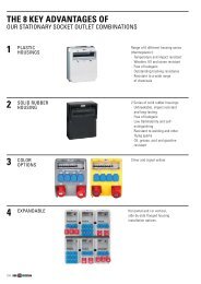
Turn your PDF publications into a flip-book with our unique Google optimized e-Paper software.
switching devices
<strong>ABL</strong> SURSUM ist seit über 90 Jahren der Spezialist für Steckvorrichtungen<br />
und Schaltgeräte. Das Familienunternehmen aus<br />
<strong>ABL</strong> Franken SURSUM produziert ist seit Elektrotechnik über 90 Jahren für der die Gebäudeinstallation,<br />
Spezialist für Steckvorrichtungen<br />
für Industrieanwendungen und Schaltgeräte. und für Das e-mobility. Familienunternehmen aus<br />
Franken produziert Elektrotechnik für die Gebäudeinstallation,<br />
für Grundlegend Industrieanwendungen für den Erfolg und war für die e-mobility. Patentierung des SCHUKO-<br />
Steckers bei <strong>ABL</strong> im Jahr 1925. Damit ist es gelungen, das heute<br />
<strong>ABL</strong> Grundlegend meistverbreitete SURSUM für offers den und Erfolg sicherste electrical war elektrische die installations Patentierung Stecksystem for des industrial SCHUKO- der Welt appli cations<br />
according to IEC world wide standards.<br />
Steckers zu entwickeln. bei <strong>ABL</strong> im Jahr 1925. Damit ist es gelungen, das heute<br />
meistverbreitete und sicherste elektrische Stecksystem der Welt<br />
We zu Etwa entwickeln. are zeitgleich a traditional, Etwa wurde zeitgleich family-owned bei SURSUM wurde der bei company SURSUM erste wieder drawing der einschaltbare<br />
erste on wieder 90 years of<br />
experience einschaltbare Sicherungsautomat in Sicherungsautomat developing, erfunden. producing Die erfunden. magnetische and Die exporting magnetische<br />
Kurzschlussaus- switching devices<br />
to countries all over the globe.<br />
Kurzschlussauslösung lösung ist Grundlage der ist Grundlage technologischen der technologischen Weiterentwicklung Weiter- aller<br />
entwicklung Schutzschaltgeräte. aller Schutzschaltgeräte.<br />
Our extensive range includes MCBs, RCCBs, RCBOs, Din-Rail Products,<br />
Logic Das Das heutige modules Produktprogramm and Motor Protection basiert auf auf Switches diesen grundlegenden<br />
for contemporary DIN-<br />
Rail Technologien. installation Es Es applications. gliedert sich sich in in Integrating die die Bereiche a Sichern, wide range Verbinden of accessories,<br />
the und und <strong>ABL</strong> Systeme. SURSUM system offers you the flexibility to create individual,<br />
state-of-the-art solutions. Made in Germany.<br />
Dr. Dr. Stefan Schlutius<br />
CEO<br />
Geschäftsführer<br />
<strong>ABL</strong>_ZWISCHENSEITEN_RZ.indd 5 15.<br />
00_Einstieg_RZ.indd 5 14.06.2011<br />
5
Sales organisation 6<br />
MiniAtuRe CiRCuit BReAkeRs 8<br />
S product range 12<br />
SL product range 15<br />
T product range 16<br />
S, SL and T, Technical data 19<br />
DC product range 28<br />
DC, Technical data 29<br />
S, SL, T and DC accessories 31<br />
S, SL, T and MA busbars 33<br />
T product range 80 A up to 125 A 35<br />
T, Technical data 80 A up to 125 A 36<br />
T accessories 80 A up to 125 A 37<br />
1+N product range 38<br />
1+N, Technical data 38<br />
1+N busbars 39<br />
4<br />
RCCB and RCBOs 40<br />
RCCB 42<br />
RW product range 42<br />
Sensitive to alternating currents, Type AC 42<br />
Undelayed tripping 42<br />
Short-time delayed tripping 45<br />
Selective tripping 45<br />
RP product range 46<br />
Sensitive to pulsating currents, Type A 46<br />
Undelayed tripping 46<br />
Short-time delayed tripping 48<br />
Selective tripping 48<br />
RA product range 49<br />
Sensitive to universal current, Type B 49<br />
Short-time delayed tripping 49<br />
Selective tripping 51<br />
Auxiliary contact 53<br />
Technical data RP und RW 54<br />
General explanations 57<br />
Technical features and application notes 59<br />
RCBO 65<br />
RC and RB product range 65<br />
Auxiliary contact 66<br />
Busbars 66<br />
Technical Data 67
Din-RAil PAnel PRODuCts 70<br />
Switches 72<br />
Buttons 73<br />
Light Signals 73<br />
SCHUKO socket outlet 73<br />
Installation relays mechanical 74<br />
Storage relays mechanical 74<br />
Electronic control relays 76<br />
Mechanical remote switches 78<br />
Remote switch central electronic control 80<br />
Touch dimmer 82<br />
Load shedding relays 83<br />
Twilight switch 84<br />
Time relays and multi-function time relays 85<br />
Mains monitoring 88<br />
Installation contactors 89<br />
Stairway light time switches 93<br />
Synchronised / Quartz time switch 95<br />
Digital timer 96<br />
Transformers 97<br />
Logic Module LoMo 98<br />
MOtOR PROteCtive CiRCuit BReAkeRs 100<br />
Motor Protective Circuit Breakers Ms 102<br />
Motor Protective Circuit Breakers MS/BS 103<br />
Transformer Protective Circuit Breakers MST 104<br />
Motor Protective Circuit Breakers MSH/MSW 105<br />
Motor Protective Devices for variable-speed fan motors 106<br />
Accessories 107<br />
Technical Data 113<br />
Motor Protective Circuit Breakers MA 116<br />
Accessories 118<br />
Busbars 118<br />
Technical Data 120<br />
Article number Directory 124<br />
5
6<br />
SALES ORGANISATION EUROPE<br />
AUSTRIA<br />
Burisch Elektro-Systemtechnik<br />
Percostraße 16<br />
1220 Wien<br />
T: +43 (1) 25 00 10<br />
F: +43 (1) 2 59 97 02<br />
office@burisch.co.at<br />
BALTICS<br />
Estland, Lettland, Litauen<br />
LASD<br />
Snikeres iela 31<br />
LV-1067 Riga, Latvia<br />
T: +371 67212435<br />
mihail@lasd.lv<br />
BELGIUm<br />
Arfa S.P.R.L.<br />
Rue A. Diderich 63<br />
1060 Bruxelles<br />
T: +32 (2) 5 39 30 54<br />
F: +32 (2) 5 39 21 44<br />
info@arfa.be<br />
SES-EUPEN AG<br />
Textilstr. 1<br />
4700 Eupen<br />
T: +32 (87) 85 90 50<br />
F: +32 (87) 85 90 59<br />
ses-eupen@ses-sterling.com<br />
CZECH TEPUBLIK<br />
EROCOMM s.r.o.<br />
Drevcice 141<br />
25001 Brandys n.L.<br />
T: +420 326 910 950<br />
F: +420 326 914 319<br />
info@erocomm.cz<br />
FInLAnd<br />
Stenbacka Oy T.<br />
Emalikatu 2 B<br />
04440 JÄRVENPÄÄ<br />
T: +358 (207) 432 320<br />
F: +358 (207) 432 349<br />
info@stenbacka.fi<br />
FRAnCE<br />
Disimpex<br />
14, rue Joseph Graff<br />
67810 Holtzheim<br />
T: +33 03 - 90 20 74 20<br />
F: +33 03 - 88 76 90 83<br />
info@disimpex.fr<br />
GREECE<br />
Christos Michelis Ltd.<br />
Halkomatadon 8<br />
14232 Nea Ionia/Athen<br />
T: +30 210 2795797<br />
F: +30 210 2724714<br />
info@michelis-electric.gr<br />
HUnGARY<br />
Burisch FKT<br />
Villanyszerel. Rendszerek<br />
Schweidel U. 2<br />
1047 Budapest<br />
T: +36 1 399 - 8026<br />
F: +36 1 369 - 5731<br />
krisztina.schallert@burisch.hu<br />
ICELAnd<br />
Reykjafell Ltd.<br />
Skipholti 35<br />
105 Reykjavik<br />
T: +354 (5) 88 60 10<br />
F: +354 (5) 88 60 88<br />
valdi@reykjafell.is<br />
ITALY<br />
GSO Components s.r.l.<br />
Via Sacco e Vanzetti, 34<br />
20099 Sesto San Giovanni, MI<br />
T: +39 02 244 17 534<br />
F: +39 02 244 17 542<br />
sales@gso-components.com<br />
nETHERLAndS<br />
Jacs. Koopman B. V.<br />
Postbus 150<br />
3960 BD Wijk bij Duurstede<br />
T: +31 (3 43) 59 22 22<br />
F: +31 (3 43) 59 23 33<br />
info@jacs-koopman.nl<br />
POLAnd<br />
<strong>ABL</strong> Polska SP.z.o.o.<br />
ul. Grzybowa 3<br />
05-092 Lomianki<br />
T: +48 (22) 8 68 24 59<br />
F: +48 (22) 8 68 24 59<br />
abl@abl-polska.pl<br />
SLOVAKIA<br />
EROCOMM SK s.r.o.<br />
Koprivnická 36<br />
84102 Bratislava<br />
T: +421 905 940 055<br />
F: +421 264 462 480<br />
info@erocomm.sk<br />
SPAIn<br />
Coma Especialidades<br />
Electricas<br />
C/ Narcis Monturiol 35<br />
08960 Sant Just Desvern<br />
(Barcelona)<br />
T: +34 (93) 4 90 46 24<br />
F: +43 (93) 3 39 52 39<br />
coma@eecoma.com<br />
SwEdEn<br />
L & K BJÖRKMAN<br />
FÖRSÄLJNINGS AB<br />
Malmgatan 18<br />
60223 Norrköping<br />
T: +46 (11) 10 53 18<br />
F: +46 (11) 16 46 84<br />
order@bjorkman-l-k.se<br />
SwITZERLAnd<br />
A. Steffen AG<br />
Limmatstr. 8<br />
8957 Spreitenbach<br />
T: +41 564179911<br />
F: +41 564179910<br />
verkauf@steffen.ch
SALES ORGANISATION WORLDWIDE<br />
ARGEnTInIA<br />
Servicios y Suministros S.A.<br />
Av. Boulogne Sur Mer 1947<br />
B 1611 BWQ Don Torcuato<br />
T: +54 11 4727 1001<br />
F: +54 11 4727 4427<br />
nestor.llorden@sysar.com.ar<br />
CHInA<br />
<strong>ABL</strong> SURSUM (Shanghai)<br />
Co., Ltd.<br />
Unit 653, German Centre<br />
88 Keyuan Road, Pudong<br />
Zhangjiang Hi-Tech Park<br />
201203 Shanghai<br />
T: +86 21 5080 5408, -4996<br />
F: +86 21 5080 4956<br />
shanghai@abl-sursum.com<br />
EGYPT<br />
Cairo Electrical Group<br />
9, Rostom Street<br />
Garden City Apt.37<br />
Maglis EL Shaab, Cairo<br />
T: +20 2 27961337<br />
F: +20 2 27962719<br />
celeg@link.com.eg<br />
GUATEmALA<br />
Electricidad General<br />
13 AVE 9-44 Z.11<br />
Colonia Roosevelt<br />
Ciudad de Guatemala<br />
T: +502 23877500<br />
F: +502 23608885<br />
info@electricidadgeneral.com<br />
IndIA<br />
<strong>ABL</strong> SURSUM India Pvt. Ltd.<br />
Plot No. 52, Udyog Vihar<br />
Phase-VI, Sector-37<br />
122001 Gurgaon-Haryana<br />
T: +91 1244121600<br />
F: +91 1244121611<br />
info@abl-sursum.com<br />
mALAYSIA<br />
Electech Distribution Syst.<br />
SDN BHD 16-1,Jln. 6/89b,<br />
Kawasan Perindustr. Trisegi,<br />
Batu 3 1/2, Off Jln. Sungai Besi<br />
57100 Kuala Lumpur<br />
T: +60 3 79818950<br />
F: +60 3 79818953<br />
tonyteh@edsm.com.my<br />
mOROCCO<br />
<strong>ABL</strong> SURSUM MOROCCO S.A.<br />
Zone Franche d‘Exportation<br />
Ilot 72 - Lot 2<br />
MA 90000 Tanger - Maroc<br />
T: +212 539 398000<br />
F: +212 539 393800<br />
alaoui@trial.ma<br />
mExICO<br />
Altech Corporacion de Mexico<br />
S de RL de CV<br />
Santa Cruz Buenavista<br />
Adolfo Lopez Mateos No. 1321-A<br />
72154 Puebla, Puebla<br />
info@altechcorp.com<br />
mIddLE EAST<br />
Afghanistan, Bahrain,<br />
Bangladesh, Brunei, Iraq, Iran,<br />
Jordan, Qatar, Kuwait, Nepal, Oman,<br />
Pakistan, Saudi Arabia, Syria, United<br />
Arab Emirates<br />
<strong>ABL</strong> SURSUM – Middle East<br />
P.O. Box 103664<br />
Dubai, U.A.E<br />
T: +971 48865202<br />
F: +971 48865203<br />
middle.east@abl-sursum.com<br />
nEw ZEALAnd<br />
Jackson Electrical Industries Ltd.<br />
18-20 Gloucester Park Road<br />
Onehunga Bay Auckland –<br />
New Zealand<br />
T: +64 9 6343376<br />
F: +64 9 6340567<br />
sales@jackson.co.nz<br />
RUSSIA<br />
<strong>ABL</strong> SURSUM<br />
Dorogobuschskaya 14,<br />
RU-121354 Moskau<br />
russia@abl-sursum.com<br />
SInGAPORE<br />
ITE Electric CO Ltd.<br />
1 Harrison Road, #01-01<br />
ITE Electric Building<br />
Singapore 369652<br />
T: +65 62852233<br />
F: +65 62843256<br />
cseng@ite.com.sg<br />
USA<br />
Altech Corp.<br />
35 Royal Road<br />
NJ 08822-6000<br />
T: +1 (9 08) 8 06 94 00<br />
F: +1 (9 08) 8 06 94 90<br />
info@altechcorp.com<br />
VEnEZUELA<br />
EPEX C.A.<br />
3ra Transversal c/c El Carmen<br />
Caracas 1070 A<br />
T: +58 212 237 3003<br />
F: +58 212 2399341<br />
www.kmsomerinca.com.ve<br />
EAST EUROPE,<br />
ASiA,<br />
AUSTRAliA,<br />
NEW ZEAlAND<br />
Department head<br />
Viktor Grünwald<br />
T: + 49 (0)9123/188-289<br />
F: + 49 (0)9123/188-188<br />
viktor.gruenwald@abl-sursum.com<br />
WEST EUROPE,<br />
NORTH AmERiCA,<br />
SOUTH AmERiCA,<br />
AfRiCA<br />
Department head<br />
Klaus Schneider<br />
T: + 49 (0)9123/188-139<br />
F: + 49 (0)9123/188-188<br />
klaus.schneider@abl-sursum.com<br />
7
sWitCHinG DeviCes<br />
MINIATURE CIRCUIT BREAKERS<br />
Miniature circuit breakers<br />
S product range 12<br />
SL product range 15<br />
T product range 16<br />
S, SL and T, Technical data 19<br />
DC product range 28<br />
DC, Technical data 29<br />
S, SL, T and DC accessories 31<br />
S, SL, T and MA busbars 33<br />
T product range 80 A up to 125 A 35<br />
T, Technical data 80 A up to 125 A 36<br />
T accessories 80 A up to 125 A 37<br />
1+N product range 38<br />
1+N, Technical data 38<br />
1+N busbars 39<br />
9
tHe WinninG FeAtuRes OF<br />
ABl SURSUm SWiTCHiNG DEViCES<br />
10<br />
1<br />
2<br />
3<br />
FUNCTIONAL FORM<br />
· User-friendly ergonomics<br />
· Intuitive product coding<br />
· Clearly marked ON/OFF positions<br />
COMPACT DESIGN OFFERING<br />
MAxIMUM WIRING SPACE<br />
At 82,5 mm height one of the smallest IEC<br />
Miniature cirquit breaker available<br />
EASIER BUSBAR REMOvAL<br />
Innovative fixing slides for easy removal from<br />
the busbar, even when feeding from the top.<br />
Rated current<br />
Characteristic<br />
Rated voltage<br />
Rated breaking<br />
capacity<br />
S and T<br />
range<br />
Height only<br />
82,5 mm<br />
No. of Poles<br />
Circuit diagram<br />
Approval<br />
Product Range
4<br />
5<br />
6<br />
<strong>SWITCHING</strong> DEvICES<br />
in a consistent and contemporary design<br />
ExTENSIvE APPLICATION<br />
POSSIBILITIES<br />
Four seperate product ranges for different application<br />
in Industry and house installation in AC and DC<br />
versions. With a wide range of trip characteristics and<br />
22 nominal ratings between 0,3 A and 63A it offers<br />
the best possible protection.<br />
Wide range of international Certificates of approvals<br />
(vDE, Germanischer LLoyd, CCC, Gost, CEBEC)<br />
· s-Range<br />
6kA in compliance with IEC60898<br />
1A-63A, in B, C, Characteristic in 1-pole, 1+N,<br />
2-pole, 3-pole, 3+N<br />
COMPLETE PRODUCT<br />
SySTEM<br />
· Full range of accessories for<br />
Circuit Breakers<br />
· Auxilliary contacts can be<br />
mounted on the left and/or<br />
on the right side<br />
· Common accessories for all<br />
product ranges<br />
7 PROFESSIONAL<br />
LABELING SySTEM<br />
· with marking window<br />
· Blank perforated labels available<br />
for one pole, two pole and<br />
three pole windows for convenient<br />
circuit indication<br />
· sl-Range<br />
6kA in compliance with IEC60898<br />
6A-20A, in B, C Characteristic in 1-pole and, 3-pole<br />
· t-Range<br />
10kA in compliance with IEC60898 and IEC 60947<br />
0,3A-63A, in B, C, D, K, Z Characteristic in<br />
1-pole, 1+N, 2-pole, 3-pole, 3+N, 4-pole<br />
· DC-Range<br />
6kA in compliance with IEC60898<br />
0,5A-63A, in B, C, Characteristic in 1-pole, 125v<br />
and 2-pole 250v DC when serial connected<br />
Auxiliary<br />
contact<br />
Shunt trip Undervoltage<br />
trip<br />
lock-off /<br />
lock-on<br />
device<br />
11
MINIATURE CIRCUIT BREAKERS S PRODUCT RANGE<br />
6 kA B and C characteristic acc. to IEC 60898-1<br />
12<br />
3<br />
3<br />
RAteD CuRRent<br />
ln A<br />
1-pole<br />
B<br />
ARtiCle nO.<br />
1 C1S1 120 12<br />
2 C2S1 120 12<br />
3 C3S1 120 12<br />
4 C4S1 120 12<br />
5 C5S1 120 12<br />
6 B6S1 C6S1 120 12<br />
10 B10S1 C10S1 120 12<br />
13 B13S1 C13S1 120 12<br />
16 B16S1 C16S1 120 12<br />
20 B20S1 C20S1 120 12<br />
25 B25S1 C25S1 120 12<br />
32 B32S1 C32S1 120 12<br />
40 B40S1 C40S1 125 12<br />
50 B50S1 C50S1 135 12<br />
63 B63S1 C63S1 135 12<br />
1-pole with switched neutral<br />
CHARACteRistiC<br />
C<br />
ARtiCle nO.<br />
WeiGHt<br />
g / eACH<br />
PACkinG<br />
unit<br />
1 C1S8 240 6<br />
2 C2S8 240 6<br />
3 C3S8 240 6<br />
4 C4S8 240 6<br />
5 C5S8 240 6<br />
6 B6S8 C6S8 240 6<br />
10 B10S8 C10S8 240 6<br />
13 B13S8 C13S8 240 6<br />
16 B16S8 C16S8 240 6<br />
20 B20S8 C20S8 240 6<br />
25 B25S8 C25S8 240 6<br />
32 B32S8 C32S8 240 6<br />
40 B40S8 C40S8 250 6<br />
50 B50S8 C50S8 270 6<br />
63 B63S8 C63S8 270 6
MINIATURE CIRCUIT BREAKERS S PRODUCT RANGE<br />
6 kA B and C characteristic acc. to IEC 60898-1<br />
3<br />
3<br />
RAteD CuRRent<br />
ln A<br />
2-pole<br />
3-pole<br />
B<br />
ARtiCle nO.<br />
CHARACteRistiC<br />
C<br />
ARtiCle nO.<br />
WeiGHt<br />
g / eACH<br />
PACkinG<br />
unit<br />
1 C1S2 240 6<br />
2 C2S2 240 6<br />
3 C3S2 240 6<br />
4 C4S2 240 6<br />
5 C5S2 240 6<br />
6 B6S2 C6S2 240 6<br />
10 B10S2 C10S2 240 6<br />
13 B13S2 C13S2 240 6<br />
16 B16S2 C16S2 240 6<br />
20 B20S2 C20S2 240 6<br />
25 B25S2 C25S2 240 6<br />
32 B32S2 C32S2 240 6<br />
40 B40S2 C40S2 250 6<br />
50 B50S2 C50S2 270 6<br />
63 B63S2 C63S2 270 6<br />
1 C1S3 360 4<br />
2 C2S3 360 4<br />
3 C3S3 360 4<br />
4 C4S3 360 4<br />
5 C5S3 360 4<br />
6 B6S3 C6S3 360 4<br />
10 B10S3 C10S3 360 4<br />
13 B13S3 C13S3 360 4<br />
16 B16S3 C16S3 360 4<br />
20 B20S3 C20S3 360 4<br />
25 B25S3 C25S3 360 4<br />
32 B32S3 C32S3 360 4<br />
40 B40S3 C40S3 375 4<br />
50 B50S3 C50S3 405 4<br />
63 B63S3 C63S3 405 4<br />
13
MINIATURE CIRCUIT BREAKERS S PRODUCT RANGE<br />
6 kA B and C characteristic acc. to IEC 60898-1<br />
14<br />
3<br />
RAteD CuRRent<br />
ln A<br />
B<br />
ARtiCle nO.<br />
3-pole with switched neutral<br />
CHARACteRistiC<br />
C<br />
ARtiCle nO.<br />
WeiGHt<br />
g / eACH<br />
PACkinG<br />
unit<br />
1 C1S9 480 3<br />
2 C2S9 480 3<br />
3 C3S9 480 3<br />
4 C4S9 480 3<br />
5 C5S9 480 3<br />
6 B6S9 C6S9 480 3<br />
10 B10S9 C10S9 480 3<br />
13 B13S9 C13S9 480 3<br />
16 B16S9 C16S9 480 3<br />
20 B20S9 C20S9 480 3<br />
25 B25S9 C25S9 480 3<br />
32 B32S9 C32S9 480 3<br />
40 B40S9 C40S9 500 3<br />
50 B50S9 C50S9 540 3<br />
63 B63S9 C63S9 540 3
MINIATURE CIRCUIT BREAKERS SL PRODUCT RANGE<br />
With screwless top terminal · 6 kA B and C characteristic acc. to IEC 60898-1<br />
3<br />
3<br />
RAteD CuRRent<br />
ln A<br />
1-pole<br />
3-pole<br />
B<br />
ARtiCle nO.<br />
CHARACteRistiC<br />
C<br />
ARtiCle nO.<br />
WeiGHt<br />
g / eACH<br />
PACkinG<br />
unit<br />
6 B6SL1 C6SL1 120 12<br />
10 B10SL1 C10SL1 120 12<br />
13 B13SL1 C13SL1 120 12<br />
16 B16SL1 C16SL1 120 12<br />
20 B20SL1 C20SL1 120 12<br />
6 B6SL3 C6SL3 360 4<br />
10 B10SL3 C10SL3 360 4<br />
13 B13SL3 C13SL3 360 4<br />
16 B16SL3 C16SL3 360 4<br />
20 B20SL3 C20SL3 360 4<br />
15
MINIATURE CIRCUIT BREAKERS T PRODUCT RANGE<br />
10 kA B, C and D characteristic acc. to IEC 60898-1<br />
10 kA K and Z characteristic acc. to IEC 60947-2<br />
16<br />
3<br />
3<br />
This product range differentiates between:<br />
· Standard products (shown in the table in bold)<br />
· Special products (shown in the table in normal print – longer delivery time)<br />
RAteD CuRRent<br />
ln A<br />
B<br />
ARtiCle nO.<br />
C<br />
ARtiCle nO.<br />
CHARACteRistiC<br />
D<br />
ARtiCle nO.<br />
k<br />
ARtiCle nO.<br />
Z<br />
ARtiCle nO.<br />
WeiGHt<br />
g / eACH<br />
1-pole<br />
0.3 C0.3T1 D0.3T1 K0.3T1 Z0.3T1 120 12<br />
0.5 C0.5T1 d0.5T1 K0.5T1 Z0.5T1 120 12<br />
0.8 C0.8T1 D0.8T1 K0.8T1 Z0.8T1 120 12<br />
1 B1T1 C1T1 d1T1 K1T1 Z1T1 120 12<br />
1.6 C1.6T1 D1.6T1 K1.6T1 Z1.6T1 120 12<br />
2 B2T1 C2T1 d2T1 K2T1 Z2T1 120 12<br />
2.5 C2.5T1 D2.5T1 K2.5T1 Z2.5T1 120 12<br />
3 B3T1 C3T1 d3T1 K3T1 Z3T1 120 12<br />
3.5 C3.5T1 D3.5T1 K3.5T1 Z3.5T1 120 12<br />
4 B4T1 C4T1 d4T1 K4T1 Z4T1 120 12<br />
5 B5T1 C5T1 D5T1 K5T1 Z5T1 120 12<br />
6 B6T1 C6T1 d6T1 K6T1 Z6T1 120 12<br />
8 C8T1 D8T1 K8T1 Z8T1 120 12<br />
10 B10T1 C10T1 d10T1 K10T1 Z10T1 120 12<br />
13 B13T1 C13T1 d13T1 K13T1 Z13T1 120 12<br />
16 B16T1 C16T1 d16T1 K16T1 Z16T1 120 12<br />
20 B20T1 C20T1 d20T1 K20T1 Z20T1 120 12<br />
25 B25T1 C25T1 d25T1 K25T1 Z25T1 120 12<br />
32 B32T1 C32T1 d32T1 K32T1 Z32T1 120 12<br />
40 B40T1 C40T1 d40T1 K40T1 125 12<br />
50 B50T1 C50T1 d50T1 * K50T1 135 12<br />
63 B63T1 C63T1 d63T1 * K63T1 135 12<br />
1-pole with switched neutral<br />
0.3 C0.3T8 D0.3T8 K0.3T8 240 6<br />
0.5 C0.5T8 d0.5T8 K0.5T8 240 6<br />
0.8 C0.8T8 D0.8T8 K0.8T8 240 6<br />
1 B1T8 C1T8 d1T8 K1T8 240 6<br />
1.6 C1.6T8 D1.6T8 K1.6T8 240 6<br />
2 B2T8 C2T8 d2T8 K2T8 240 6<br />
2.5 C2.5T8 D2.5T8 K2.5T8 240 6<br />
3 B3T8 C3T8 d3T8 K3T8 240 6<br />
3.5 C3.5T8 D3.5T8 K3.5T8 240 6<br />
4 B4T8 C4T8 d4T8 K4T8 240 6<br />
5 B5T8 C5T8 D5T8 K5T8 240 6<br />
6 B6T8 C6T8 d6T8 K6T8 240 6<br />
8 C8T8 D8T8 K8T8 240 6<br />
10 B10T8 C10T8 d10T8 K10T8 240 6<br />
13 B13T8 C13T8 d13T8 K13T8 240 6<br />
16 B16T8 C16T8 d16T8 K16T8 240 6<br />
20 B20T8 C20T8 d20T8 K20T8 240 6<br />
25 B25T8 C25T8 d25T8 K25T8 240 6<br />
32 B32T8 C32T8 d32T8 K32T8 240 6<br />
40 B40T8 C40T8 d40T8 K40T8 250 6<br />
50 B50T8 C50T8 d50T8 * K50T8 270 6<br />
63 B63T8 C63T8 d63T8 * K63T8 270 6<br />
* 10 kA acc. to iEC 60947-2<br />
PACkinG<br />
unit
MINIATURE CIRCUIT BREAKERS T PRODUCT RANGE<br />
10 kA B, C and D characteristic acc. to IEC 60898-1<br />
10 kA K and Z characteristic acc. to IEC 60947-2<br />
3<br />
3<br />
This product range differentiates between:<br />
· Standard products (shown in the table in bold)<br />
· Special products (shown in the table in normal print – longer delivery time)<br />
RAteD CuRRent<br />
ln A<br />
B<br />
ARtiCle nO.<br />
C<br />
ARtiCle nO.<br />
CHARACteRistiC<br />
D<br />
ARtiCle nO.<br />
k<br />
ARtiCle nO.<br />
Z<br />
ARtiCle nO.<br />
WeiGHt<br />
g / eACH<br />
2-pole<br />
0.3 C0.3T2 D0.3T2 K0.3T2 Z0.3T2 240 6<br />
0.5 C0.5T2 d0.5T2 K0.5T2 Z0.5T2 240 6<br />
0.8 C0.8T2 D0.8T2 K0.8T2 Z0.8T2 240 6<br />
1 B1T2 C1T2 d1T2 K1T2 Z1T2 240 6<br />
1.6 C1.6T2 D1.6T2 K1.6T2 Z1.6T2 240 6<br />
2 B2T2 C2T2 d2T2 K2T2 Z2T2 240 6<br />
2.5 C2.5T2 D2.5T2 K2.5T2 Z2.5T2 240 6<br />
3 B3T2 C3T2 d3T2 K3T2 Z3T2 240 6<br />
3.5 C3.5T2 D3.5T2 K3.5T2 Z3.5T2 240 6<br />
4 B4T2 C4T2 d4T2 K4T2 Z4T2 240 6<br />
5 B5T2 C5T2 D5T2 K5T2 Z5T2 240 6<br />
6 B6T2 C6T2 d6T2 K6T2 Z6T2 240 6<br />
8 C8T2 D8T2 K8T2 Z8T2 240 6<br />
10 B10T2 C10T2 d10T2 K10T2 Z10T2 240 6<br />
13 B13T2 C13T2 d13T2 K13T2 Z13T2 240 6<br />
16 B16T2 C16T2 d16T2 K16T2 Z16T2 240 6<br />
20 B20T2 C20T2 d20T2 K20T2 Z20T2 240 6<br />
25 B25T2 C25T2 d25T2 K25T2 Z25T2 240 6<br />
32 B32T2 C32T2 d32T2 K32T2 Z32T2 240 6<br />
40 B40T2 C40T2 d40T2 K40T2 250 6<br />
50 B50T2 C50T2 d50T2 * K50T2 270 6<br />
63 B63T2 C63T2 d63T2 * K63T2 270 6<br />
3-pole<br />
0.3 C0.3T3 D0.3T3 K0.3T3 Z0.3T3 360 4<br />
0.5 C0.5T3 d0.5T3 K0.5T3 Z0.5T3 360 4<br />
0.8 C0.8T3 D0.8T3 K0.8T3 Z0.8T3 360 4<br />
1 B1T3 C1T3 d1T3 K1T3 Z1T3 360 4<br />
1.6 C1.6T3 D1.6T3 K1.6T3 Z1.6T3 360 4<br />
2 B2T3 C2T3 d2T3 K2T3 Z2T3 360 4<br />
2.5 C2.5T3 D2.5T3 K2.5T3 Z2.5T3 360 4<br />
3 B3T3 C3T3 d3T3 K3T3 Z3T3 360 4<br />
3.5 C3.5T3 D3.5T3 K3.5T3 Z3.5T3 360 4<br />
4 B4T3 C4T3 d4T3 K4T3 Z4T3 360 4<br />
5 B5T3 C5T3 D5T3 K5T3 Z5T3 360 4<br />
6 B6T3 C6T3 d6T3 K6T3 Z6T3 360 4<br />
8 C8T3 D8T3 K8T3 Z8T3 360 4<br />
10 B10T3 C10T3 d10T3 K10T3 Z10T3 360 4<br />
13 B13T3 C13T3 d13T3 K13T3 Z13T3 360 4<br />
16 B16T3 C16T3 d16T3 K16T3 Z16T3 360 4<br />
20 B20T3 C20T3 d20T3 K20T3 Z20T3 360 4<br />
25 B25T3 C25T3 d25T3 K25T3 Z25T3 360 4<br />
32 B32T3 C32T3 d32T3 K32T3 Z32T3 360 4<br />
40 B40T3 C40T3 d40T3 K40T3 375 4<br />
50 B50T3 C50T3 d50T3 * K50T3 405 4<br />
63 B63T3 C63T3 d63T3 * K63T3 405 4<br />
* 10 kA acc. to iEC 60947-2<br />
PACkinG<br />
unit<br />
17
MINIATURE CIRCUIT BREAKERS T PRODUCT RANGE<br />
10 kA B, C and D characteristic acc. to IEC 60898-1<br />
10 kA K and Z characteristic acc. to IEC 60947-2<br />
18<br />
3<br />
3<br />
This product range differentiates between:<br />
· Standard products (shown in the table in bold)<br />
· Special products (shown in the table in normal print – longer delivery time)<br />
RAteD CuRRent<br />
ln A<br />
B<br />
ARtiCle nO.<br />
C<br />
ARtiCle nO.<br />
CHARACteRistiC<br />
D<br />
ARtiCle nO.<br />
k<br />
ARtiCle nO.<br />
Z<br />
ARtiCle nO.<br />
WeiGHt<br />
g / eACH<br />
3-pole with switched neutral<br />
0.3 C0.3T9 D0.3T9 K0.3T9 480 3<br />
0.5 C0.5T9 d0.5T9 K0.5T9 480 3<br />
0.8 C0.8T9 D0.8T9 K0.8T9 480 3<br />
1 B1T9 C1T9 d1T9 K1T9 480 3<br />
1.6 C1.6T9 D1.6T9 K1.6T9 480 3<br />
2 B2T9 C2T9 d2T9 K2T9 480 3<br />
2.5 C2.5T9 D2.5T9 K2.5T9 480 3<br />
3 B3T9 C3T9 d3T9 K3T9 480 3<br />
3.5 C3.5T9 D3.5T9 K3.5T9 480 3<br />
4 B4T9 C4T9 d4T9 K4T9 480 3<br />
5 B5T9 C5T9 D5T9 K5T9 480 3<br />
6 B6T9 C6T9 d6T9 K6T9 480 3<br />
8 C8T9 D8T9 K8T9 480 3<br />
10 B10T9 C10T9 d10T9 K10T9 480 3<br />
13 B13T9 C13T9 d13T9 K13T9 480 3<br />
16 B16T9 C16T9 d16T9 K16T9 480 3<br />
20 B20T9 C20T9 d20T9 K20T9 480 3<br />
25 B25T9 C25T9 d25T9 K25T9 480 3<br />
32 B32T9 C32T9 d32T9 K32T9 480 3<br />
40 B40T9 C40T9 d40T9 K40T9 500 3<br />
50 B50T9 C50T9 d50T9 * K50T9 540 3<br />
63 B63T9 C63T9 d63T9 * K63T9 540 3<br />
4-pole<br />
0.3 C0.3T4 D0.3T4 K0.3T4 480 3<br />
0.5 C0.5T4 d0.5T4 K0.5T4 480 3<br />
0.8 C0.8T4 D0.8T4 K0.8T4 480 3<br />
1 B1T4 C1T4 d1T4 K1T4 480 3<br />
1.6 C1.6T4 D1.6T4 K1.6T4 480 3<br />
2 B2T4 C2T4 d2T4 K2T4 480 3<br />
2.5 C2.5T4 D2.5T4 K2.5T4 480 3<br />
3 B3T4 C3T4 d3T4 K3T4 480 3<br />
3.5 C3.5T4 D3.5T4 K3.5T4 480 3<br />
4 B4T4 C4T4 d4T4 K4T4 480 3<br />
5 B5T4 C5T4 D5T4 K5T4 480 3<br />
6 B6T4 C6T4 d6T4 K6T4 480 3<br />
8 C8T4 D8T4 K8T4 480 3<br />
10 B10T4 C10T4 d10T4 K10T4 480 3<br />
13 B13T4 C13T4 d13T4 K13T4 480 3<br />
16 B16T4 C16T4 d16T4 K16T4 480 3<br />
20 B20T4 C20T4 d20T4 K20T4 480 3<br />
25 B25T4 C25T4 d25T4 K25T4 480 3<br />
32 B32T4 C32T4 d32T4 K32T4 480 3<br />
40 B40T4 C40T4 d40T4 K40T4 500 3<br />
50 B50T4 C50T4 d50T4 * K50T4 540 3<br />
63 B63T4 C63T4 d63T4 * K63T4 540 3<br />
* 10 kA acc. to iEC 60947-2<br />
PACkinG<br />
unit
MINIATURE CIRCUIT BREAKERS S, SL AND T PRODUCT RANGES<br />
Technical Data<br />
Characteristic B C d K Z<br />
Application Wiring protection<br />
Wiring protection<br />
Device protection<br />
Wiring protection<br />
Power circuits<br />
Transformers<br />
Motors<br />
Wiring protection<br />
Power circuits<br />
Transformers<br />
Motors<br />
Wiring protection<br />
Semiconductor<br />
protection<br />
High impedance<br />
Number of poles<br />
Product range „S“ 1-3; 1+N; 3+N - - -<br />
Product range „SL“ 1 and 3 - - -<br />
Product range „T“ 1 - 4; 1 + N; 3 + N 1 - 3<br />
Standards<br />
short circuit withstand rating<br />
IEC 60898-1, DIN EN 60898-1, VDE 0641-11 IEC 60947-2, DIN EN 60947-2, VDE 0660-101<br />
Product range „S“ 6 kA 6 kA - - -<br />
Product range „SL“ 6 kA 6 kA - - -<br />
Product range „T“ 10 kA 10 kA 10 kA 10 kA 10 kA<br />
Current limiting class 3 3<br />
Max. back-up fuse Fuse according to DIN VDE 0636 125 A operating class gL/gG<br />
Rated AC voltage 230 / 400 V<br />
Rated DC voltage<br />
L/R = 4 ms<br />
Rated current range In<br />
1-pole 60 V,<br />
2-pole 125 V in serial connection of both poles<br />
Product range „S“ 6 - 63 A 1 - 63 A - - -<br />
Product range „SL“ 6 - 20 A 6 - 20 A - - -<br />
Product range „T“ 1 - 63 A 0.3 - 63 A 0,3 - 63 A 0.3 - 63 A 0.3 - 32 A<br />
Thermal<br />
not tripping I1 (A) > 1 h<br />
1.13 x In 1.13 x In 1.13 x In 1.05 x In 1.05 x In<br />
Thermal<br />
tripping I2 (A) < 1 h<br />
1.45 x In 1.45 x In 1.45 x In 1.2 x In 1.35 x In<br />
Electromagnetic<br />
not tripping I4 (A) > 0,1 s<br />
3 x In 5 x In 10 x In 8 x In 2 x In<br />
Electromagnetic<br />
tripping I5 (A) < 0,1 s<br />
5 x In 10 x In 20 x In 12 x In 3 x In<br />
30° C + 5° C 20° C + 5° C<br />
Reference calibration temperature<br />
of the thermal tripping<br />
Influence of the ambient temperature on the thermal tripping: Decrease of the current values with higher<br />
ambient temperature and increase with lower temperatures of approximately 5% per 10°C difference in temperature<br />
Test currents<br />
Frequency range of the<br />
electromagnetic trip<br />
16 2 / 3 to 60 Hz<br />
With higher frequencies, the electromagnetic tripping values increase by approximately<br />
a factor of 1.1 at 100 Hz; 1.2 at 200 Hz; 1.3 at 300 Hz; 1.4 at 400 Hz; 1.5 for DC<br />
Ambient temperature -25° C to +55° C<br />
Storage temperature -40° C to +70° C<br />
Device depth acc. to DIN 43880 68 mm<br />
Mechanical endurance 20,000 switching cycles (20,000 ON / 20,000 OFF)<br />
Protection cover Finger safe and safe to back of hand according to DIN EN 50274/ VDE0660-514, BGV A3<br />
Insulation group<br />
according to DIN VDE 0110<br />
Degree of protection according<br />
to EN / IEC 60529<br />
C at 250 V AC<br />
B at 400 V AC<br />
Installation position any<br />
Mounting DIN-rail according to DIN EN 60715 35 mm<br />
Lockability The handle can be secured against manual switching in the on and off position by a lead seal<br />
Climatic resistance<br />
IP20<br />
Humid heat constant according to DIN IEC 60068-2-78<br />
Humid heat cycle according to DIN EN 60068-2-30<br />
Vibration resistance > 15 g according to DIN EN 60068-2-59 during a load with I1<br />
Resistance to mechanical shocks 25g 11ms<br />
19
MINIATURE CIRCUIT BREAKERS S, SL AND T PRODUCT RANGES<br />
Technical Data<br />
Additional performance features of the T product range – short circuit withstand rating according to IEC 60947-2, dIn En 60947-2<br />
Characteristic B, C, d, K, Z<br />
1-pole 0.3 - 40 A 254/440 V 10 kA<br />
2-pole / 3-pole 0.3 - 40 A 440 V 10 kA<br />
Characteristic B, C<br />
1-pole 0.3 - 20 A 230/400 V 20 kA<br />
Conductor cross sections product ranges S and T<br />
20<br />
Box terminal bottom Box terminal top<br />
Type of conductor *) max. min. max. min.<br />
Single wire 35 mm 2 0.5 mm 2 25 mm 2 0.5 mm 2<br />
Multiple wire 35 mm 2 1.5 mm 2 25 mm 2 1.5 mm 2<br />
Stranded wire 25 mm 2 1 mm 2 16 mm 2 1 mm 2<br />
Stranded wire with ferrule 16 mm 2 0.5 mm 2 16 mm 2 0.5 mm 2<br />
Busbar cable lug Up to 3 mm thickness Up to 3 mm thickness<br />
Combined, conductor and<br />
busbar or cable lug<br />
Up to 35 mm 2 and<br />
up to 2 mm thickness<br />
Torque max. 2.5 Nm<br />
Up to 25 mm 2 and<br />
up to 2 mm thickness<br />
Conductor cross sections SL product range<br />
Box terminal bottom Screwless terminal top<br />
Type of conductor *) max. min. max. min.<br />
Single wire 35 mm2 0.5 mm2 4 mm2 1 mm2 Multiple wire 35 mm2 1.5 mm2 4 mm2 1.5 mm2 Stranded wire 25 mm2 1 mm2 4 mm2 1 mm2 Stranded wire with ferrule 16 mm2 0.5 mm2 2.5 mm2 1 mm2 Busbar cable lug Up to 3 mm thickness -<br />
Combined, conductor and<br />
busbar or cable lug<br />
Up to 35 mm2 and<br />
up to 2 mm thickness<br />
-<br />
Torque<br />
*) Stripped length 12 – 14 mm<br />
max. 2.5 Nm -<br />
The following characteristics can<br />
be chosen:<br />
· B characteristic for wiring<br />
protection<br />
· C characteristic for device<br />
protection with higher starting<br />
current inrush<br />
· D characteristic for the<br />
protection of power circuits,<br />
motors and transformers<br />
· K characteristic for the<br />
protection of power circuits,<br />
motors and transformers<br />
· Z characteristic for semiconductor<br />
protection at high impedances<br />
S Range SL Range T Range<br />
no. of Poles 1 2 3 1+n 3+n 1 3 1 2 3 4 1+n 3+n<br />
B-characteristic • • • • • • • • • • • • •<br />
C-characteristic • • • • • • • • • • • • •<br />
D-characteristic • • • • • •<br />
K-characteristic • • • • • •<br />
Z-characteristic • • •<br />
Standard products Standard products Special products
MINIATURE CIRCUIT BREAKERS S, SL AND T PRODUCT RANGES<br />
Dimension Drawings<br />
Miniature circuit breakers, s product range<br />
· with screw terminals<br />
1-pole 2-pole 3-pole 3-pole with<br />
switched neutral<br />
Miniature circuit breakers, sl product range<br />
· with screwless terminals<br />
1-pole 3-pole<br />
Miniature circuit breakers, t product range<br />
· with screw terminals<br />
1-pole 2-pole or 1-pole<br />
3-pole 4-pole or 3-pole<br />
with switched<br />
with switched<br />
neutral<br />
neutral<br />
21
MINIATURE CIRCUIT BREAKERS S, SL AND T PRODUCT RANGES<br />
Characteristic acc. to IEC 60898-1<br />
Delayed thermal overload tripping<br />
in = Rated current<br />
Current which the miniature circuit breaker<br />
can sustain in uninterrupted operation<br />
ib = Rated operational current<br />
Current determined by the load during<br />
undisturbed operation<br />
i1 = thermal not tripping current<br />
Current which, under defined conditions,<br />
does not lead to switching off within 60 min<br />
i2 = thermal tripping current<br />
Current which, under defined conditions,<br />
leads to switching off within 60 min<br />
i1 zu i2 = Conditions<br />
Current which, under defined conditions, is run<br />
up from I1 to I2 with a continuous increase,<br />
and leads to switch off within 60 min<br />
i3 = tolerance limitation<br />
at 2.55-times the rated current / nominal current<br />
Current which, under defined conditions, does<br />
not lead to switch off within 1 sec<br />
Current which, under defined conditions, leads to<br />
switch off at rated currents up to 32 A within<br />
60 sec, at rated currents above 32 A within 120 sec<br />
22<br />
1,13 – 1,45 x ln<br />
minutes<br />
Seconds<br />
x Rated current<br />
B-C-D characteristic in = 0,3 - 8 A<br />
1,13 – 1,45 x ln<br />
Seconds minutes<br />
60<br />
40<br />
0,4<br />
10<br />
10<br />
10<br />
10<br />
4<br />
1<br />
10<br />
4<br />
1<br />
-1<br />
-2<br />
4x10<br />
-2<br />
-3<br />
4x10<br />
-3<br />
12 34 56 81 02 16 04 0 100<br />
x Rated current<br />
B-C-D characteristic in = 10 - 63 A<br />
undelayed electromagnetic short circuit tripping<br />
i4 = Magnetic not tripping current<br />
Current which, under defined conditions, does<br />
not lead to switching off within 0.1 sec<br />
i5 = Magnetic tripping current<br />
Current which, under defined conditions, leads<br />
to switching off within 0.1 sec<br />
Dependence of the short circuit trip at higher<br />
frequencies and for direct current.<br />
at 100 Hz about 1.1 times<br />
at 200 Hz about 1.2 times<br />
at 300 Hz about 1.3 times<br />
at 400 Hz about 1.4 times<br />
at 500 Hz about 1.5 times<br />
for DC about 1.5 times
MINIATURE CIRCUIT BREAKERS T PRODUCT RANGE<br />
Characteristic acc. to IEC 60947-2<br />
1,05 – 1,2 x ln<br />
Seconds minutes<br />
1,05 – 1,35 x ln<br />
Seconds minutes<br />
x Rated current<br />
1,05 – 1,2 x ln<br />
K characteristic in = 0,3 - 10 A K characteristic in = 13 - 63 A<br />
x Rated current<br />
1,05 – 1,35 x ln<br />
Z characteristic in = 0,3 - 10 A Z characteristic in = 13 - 32 A<br />
Seconds minutes<br />
Seconds minutes<br />
x Rated current<br />
x Rated current<br />
23
MINIATURE CIRCUIT BREAKERS S, SL AND T PRODUCT RANGES<br />
Technical Data<br />
Internal resistances in mOhm and power losses in watt per pole (at In)<br />
Overload and short circuit currents<br />
24<br />
RAteD CuRRent<br />
ln (A)<br />
B-CHARACteRistiC C-CHARACteRistiC D-CHARACteRistiC k-CHARACteRistiC Z-CHARACteRistiC<br />
inteRnAl<br />
ResistAnCe<br />
mOhm<br />
POWeR lOss<br />
Watt<br />
inteRnAl<br />
ResistAnCe<br />
mOhm.<br />
POWeR lOss<br />
Watt<br />
inteRnAl<br />
ResistAnCe<br />
mOhm.<br />
POWeR lOss<br />
Watt<br />
inteRnAl<br />
ResistAnCe<br />
mOhm.<br />
OveRlOAD sHORt CiRCuit<br />
POWeR lOss<br />
Watt<br />
inteRnAl<br />
ResistAnCe<br />
mOhm.<br />
0,3 - - 16600 1,5 16600,0 1,5 16860,0 1,5 31500,0 2,8<br />
0,5 - - 6850 1,7 6850,0 1,7 6850,0 1,7 10250,0 2,6<br />
0,8 - - 3050 2,0 3050,0 2,0 3050,0 2,0 5150,0 3,3<br />
1 1950 2,0 1750 1,8 1750,0 1,8 1750,0 1,8 2690,0 2,7<br />
1,6 - - 590 1,5 590,0 1,5 590,0 1,5 940,0 2,4<br />
2 510 2,0 420 1,7 420,0 1,7 420,0 1,7 690,0 2,8<br />
2,5 - - 295 1,8 295,0 1,8 295,0 1,8 430,0 2,7<br />
3 211 1,9 200 1,8 173,0 1,6 200,0 1,8 345,0 3,1<br />
3,5 - - 125 1,5 125,0 1,5 125,0 1,5 225,0 2,8<br />
4 131 2,1 109 1,7 105,0 1,7 109,0 1,7 225,0 3,6<br />
5 85 2,1 61,6 1,5 61,6 1,5 65,4 1,6 105,0 2,6<br />
6 52,9 1,9 49,1 1,8 45,9 1,7 49,1 1,8 82,3 3,0<br />
8 - - 24 1,5 20,7 1,3 44,0 2,8 37,1 2,4<br />
10 13,4 1,3 13,4 1,3 13,4 1,3 31,5 3,1 27,8 2,8<br />
13 11,3 1,9 8,04 1,4 8,1 1,4 8,8 1,5 15,1 2,6<br />
16 8,04 2,1 8,04 2,1 8,1 2,1 7,5 1,9 11,3 2,9<br />
20 7,1 2,8 7,45 3,0 6,4 2,5 6,3 2,5 7,4 3,0<br />
25 5 3,1 5 3,1 4,1 2,5 4,7 2,9 5,8 3,7<br />
32 3,6 3,7 3,6 3,7 2,7 2,8 2,8 2,9 3,6 3,7<br />
40 2,2 3,5 2,2 3,5 2,2 3,5 2,2 3,5 - -<br />
50 1,95 4,9 1,9 4,8 1,8 4,6 2,0 4,9 - -<br />
63 1,77 7,0 1,77 7,0 1,7 6,8 1,8 7,0 - -<br />
B, C, D k Z B C D k Z<br />
l1 l2 l1 l2 l1 l2 l4 l5 l4 l5 l4 l5 l4 l5 l4 l5<br />
In (A) 1,13 1,45 1,05 1,2 1,05 1,35 3 5 5 10 10 20 8 12 2 3<br />
0,3 0,339 0,435 0,315 0,360 0,315 0,405 - - 1,5 3 3 6 2,4 3,6 0,6 0,9<br />
0,5 0,565 0,725 0,525 0,600 0,525 0,675 - - 2,5 5 5 10 4 6 1 1,5<br />
0,75 0,848 1,088 0,788 0,900 0,788 1,013 - - 3,75 7,5 7,5 15 6 9 1,5 2,25<br />
1 1,13 1,45 1,05 1,20 1,05 1,35 3 5 5 10 10 20 8 12 2 3<br />
1,6 1,81 2,32 1,68 1,92 1,68 2,16 - - 8 16 16 32 12,8 19,2 3,2 4,8<br />
2 2,26 2,90 2,10 2,40 2,10 2,70 6 10 10 20 20 40 16 24 4 6<br />
2,5 2,83 3,63 2,63 3,00 2,63 3,38 - - 12,5 25 25 50 20 30 5 7,5<br />
3 3,39 4,35 3,15 3,60 3,15 4,05 9 15 15 30 30 60 24 36 6 9<br />
3,5 3,96 5,08 3,68 4,20 3,68 4,73 - - 17,5 35 35 70 28 42 7 10,5<br />
4 4,52 5,80 4,20 4,80 4,20 5,40 12 20 20 40 40 80 32 48 8 12<br />
5 5,65 7,25 5,25 6,00 5,25 6,75 15 25 25 50 50 100 40 60 10 15<br />
6 6,78 8,70 6,30 7,20 6,30 8,10 18 30 30 60 60 120 48 72 12 18<br />
8 9,04 11,60 8,40 9,60 8,40 10,80 - - 40 80 80 160 64 96 16 24<br />
10 11,3 14,5 10,5 12,0 10,5 13,5 30 50 50 100 100 200 80 120 20 30<br />
13 14,7 18,9 13,7 15,6 13,7 17,6 39 65 65 130 130 260 104 156 26 39<br />
16 18,1 23,2 16,8 19,2 16,8 21,6 48 80 80 160 160 320 128 192 32 48<br />
20 22,6 29,0 21,0 24,0 21,0 27,0 60 100 100 200 200 400 160 240 40 60<br />
25 28,3 36,3 26,3 30,0 26,3 33,8 75 125 125 250 250 500 200 300 50 75<br />
32 36,2 46,4 33,6 38,4 33,6 43,2 96 160 160 320 320 640 256 384 64 96<br />
40 45,2 58,0 42,0 48,0 - - 120 200 200 400 400 800 320 480 - -<br />
50 56,5 72,5 52,5 60,0 - - 150 250 250 500 500 1000 400 600 - -<br />
63 71,2 91,4 66,2 75,6 - - 189 315 315 630 630 1260 504 756 - -<br />
POWeR lOss<br />
Watt
MINIATURE CIRCUIT BREAKERS S, SL AND T PRODUCT RANGES<br />
Short circuit selectivity<br />
6 kA miniature circuit breakers, S and SL product ranges<br />
Short circuit selectivity to fuses in kA<br />
Characteristic<br />
In (A)<br />
LV HRC fuse<br />
Characteristic gL/gG according<br />
to DIN VDE 0636<br />
B<br />
C<br />
6<br />
25<br />
0,85<br />
35<br />
50<br />
63<br />
80<br />
1,6<br />
2,4<br />
3,5<br />
5,0<br />
100 6,0<br />
125 6,0<br />
6<br />
0,7<br />
1,3<br />
2,1<br />
2,9<br />
4,1<br />
6,0<br />
6,0<br />
10<br />
0,8<br />
1,6<br />
2,35<br />
3,3<br />
4,8<br />
6,0<br />
6,0<br />
10 kA miniature circuit breakers, T product range<br />
Short circuit selectivity to fuses in kA<br />
LV HRC fuse<br />
Characteristic gL/gG according to DIN VDE 0636<br />
10<br />
0,7<br />
1,3<br />
2,1<br />
2,8<br />
4,0<br />
6,0<br />
6,0<br />
13<br />
0,8<br />
1,5<br />
2,3<br />
3,2<br />
4,7<br />
6,0<br />
6,0<br />
13<br />
0,7<br />
1,25<br />
2,0<br />
2,7<br />
3,9<br />
5,9<br />
6,0<br />
16<br />
0,75<br />
1,5<br />
2,3<br />
3,2<br />
4,6<br />
6,0<br />
6,0<br />
Rated current In (A)<br />
16<br />
0,65<br />
1,2<br />
2,0<br />
2,7<br />
3,9<br />
5,7<br />
6,0<br />
20<br />
0,7<br />
1,4<br />
2,2<br />
3,0<br />
4,3<br />
6,0<br />
6,0<br />
20<br />
0,6<br />
1,2<br />
1,9<br />
2,6<br />
3,6<br />
5,0<br />
6,0<br />
25<br />
0,6<br />
1,2<br />
1,6<br />
2,5<br />
3,4<br />
5,1<br />
6,0<br />
Rated current In (A)<br />
B 6<br />
10<br />
13<br />
16<br />
20<br />
25<br />
32<br />
40<br />
50<br />
63<br />
Characteristic C 6/8<br />
10<br />
13<br />
16<br />
20<br />
25<br />
32<br />
40<br />
50<br />
63<br />
D<br />
6/8<br />
10<br />
13<br />
16<br />
20<br />
25<br />
32<br />
40<br />
50<br />
63<br />
In (A)<br />
0,85 0,8<br />
0,8<br />
0,75 0,7<br />
0,6<br />
25 0,7<br />
0,7<br />
0,7 0,65 0,6 0,55<br />
1.)<br />
0,7<br />
0,6<br />
0,6<br />
0,6 0,55<br />
0,5<br />
1,6<br />
1,6<br />
1,5<br />
1,5<br />
1,4<br />
1,2<br />
1,1<br />
0,8<br />
35 1,3<br />
1,3 1,25 1,2<br />
1,2<br />
1,1<br />
1,0<br />
0,7<br />
1,2 1,15<br />
1,1<br />
1,1<br />
1,0<br />
0,9<br />
0,8<br />
0,5<br />
2,4<br />
2,35 2,3<br />
2,3<br />
2,2<br />
1,6<br />
1,5<br />
1,3<br />
1,2<br />
50 2,1<br />
2,1<br />
2,0<br />
2,0<br />
1,9<br />
1,5<br />
1,4<br />
1,2<br />
1,1<br />
1,9<br />
1,8<br />
1,7<br />
1,7<br />
1,6<br />
1,3<br />
1,2<br />
1,1<br />
1,0<br />
3,5<br />
3,3<br />
3,2<br />
3,2<br />
3,0<br />
2,5<br />
2,4<br />
1,8<br />
1,7<br />
1,6<br />
63 2,9<br />
2,8<br />
2,7<br />
2,7<br />
2,6<br />
2,1<br />
2,0<br />
1,6<br />
1,5<br />
1,4<br />
2,5<br />
2,4<br />
2,4<br />
2,3<br />
2,3<br />
1,8<br />
1,8<br />
1,4<br />
1,3<br />
1,2<br />
5,0<br />
4,8<br />
4,7<br />
4,6<br />
4,3<br />
3,4<br />
3,3<br />
2,5<br />
2,4<br />
2,3<br />
80 4,1<br />
4,0<br />
3,9<br />
3,9<br />
3,6<br />
2,8<br />
2,8<br />
2,1<br />
2,0<br />
1,9<br />
3,5<br />
3,4<br />
3,3<br />
3,2<br />
3,1<br />
2,5<br />
2,4<br />
1,9<br />
1,8<br />
1,7<br />
7,6<br />
7,3<br />
7,1<br />
7,0<br />
6,5<br />
5,1<br />
5,0<br />
3,5<br />
3,3<br />
3,1<br />
100 6,3<br />
6,1<br />
5,9<br />
5,7<br />
5,0<br />
4,0<br />
3,9<br />
2,9<br />
2,8<br />
2,6<br />
5,2<br />
4,9<br />
4,8<br />
4,7<br />
4,4<br />
3,5<br />
3,4<br />
2,5<br />
2,4<br />
2,3<br />
10<br />
10<br />
10<br />
10<br />
10<br />
8,8<br />
8,5<br />
5,4<br />
5,1<br />
4,9<br />
125 10<br />
10<br />
10<br />
10<br />
8,7<br />
6,9<br />
6,8<br />
4,5<br />
4,3<br />
4,1<br />
8,8<br />
8,0<br />
7,7<br />
7,6<br />
7,1<br />
5,7<br />
5,6<br />
3,8<br />
3,6<br />
3,5<br />
1.) There is no more overload selectivity above the step line.<br />
25<br />
0,55<br />
1,1<br />
1,5<br />
2,1<br />
2,8<br />
4,0<br />
6,0<br />
32<br />
1,1<br />
1,5<br />
2,4<br />
3,3<br />
5,0<br />
6,0<br />
2,8<br />
32<br />
1,0<br />
1,4<br />
2,0<br />
3,9<br />
6,0<br />
40<br />
0,8<br />
1,3<br />
1,8<br />
2,5<br />
3,5<br />
5,4<br />
40<br />
0,7<br />
1,2<br />
1,6<br />
2,1<br />
2,9<br />
4,5<br />
50<br />
1,2<br />
1,7<br />
2,4<br />
3,3<br />
5,1<br />
50<br />
1,1<br />
1,5<br />
2,0<br />
2,8<br />
4,3<br />
63<br />
1,6<br />
2,3<br />
3,1<br />
4,9<br />
63<br />
1,4<br />
1,9<br />
2,6<br />
4,1<br />
25
MINIATURE CIRCUIT BREAKERS S AND T PRODUCT RANGES<br />
Short circuit selectivity<br />
10KA minature circuit breakers, T product range · Short circuit selectivity to minature Circuit breakers in A<br />
26<br />
Characteristic<br />
Miniature circuit breakers B-characteristic (A)<br />
B 6<br />
C<br />
D<br />
20<br />
25<br />
80<br />
6<br />
80<br />
6<br />
80<br />
10<br />
80<br />
10<br />
80<br />
100 100<br />
100 100<br />
100<br />
10<br />
13<br />
13<br />
125 125 125<br />
32 125 125 125<br />
125 125<br />
13<br />
16<br />
100 100<br />
16<br />
125<br />
125<br />
160 160 160 160 160<br />
40 160 160 160 160 160<br />
160 160 160 160<br />
50<br />
200<br />
200<br />
200<br />
200<br />
200<br />
200<br />
200<br />
200<br />
200<br />
16<br />
200<br />
200<br />
200<br />
20<br />
125<br />
Rated curent In (A)<br />
20<br />
20<br />
200<br />
200<br />
200<br />
25<br />
160<br />
25<br />
200<br />
200<br />
250 250 250 250 250 250 250<br />
63 250 250 250 250 250 250 250<br />
250 250 250 250 250 250<br />
350 350 350 350 350 350 350<br />
80 350 350 350 350 350 350 350<br />
350 350 350 350 350 350<br />
25<br />
32<br />
200<br />
32<br />
32<br />
40<br />
250<br />
40<br />
350<br />
350<br />
450 450 450 450 450 450 450 450 450 450<br />
100 450 450 450 450 450 450 450 450 450 450<br />
450 450 450 450 450 450 450 450 450 450<br />
125<br />
500<br />
500<br />
500<br />
500<br />
500<br />
500<br />
500<br />
500<br />
500<br />
500<br />
500<br />
500<br />
500<br />
500<br />
500<br />
500<br />
500<br />
500<br />
10KA minature circuit breakers, T product range · Short circuit selectivity to minature Circuit breakers in A<br />
Characteristic<br />
Miniature circuit breakers C-characteristic (A)<br />
B 6<br />
C<br />
D<br />
20<br />
25<br />
6<br />
6<br />
10<br />
10<br />
10<br />
160 160<br />
160 160<br />
160 160<br />
200<br />
200<br />
200<br />
200<br />
200<br />
200<br />
13<br />
13<br />
13<br />
200<br />
200<br />
200<br />
16<br />
16<br />
16<br />
200<br />
200<br />
200<br />
250 250 250 250 250<br />
32 250 250 250 250 250<br />
250 250 250 250<br />
20<br />
Rated curent In (A)<br />
320 320 320 320 320 320<br />
40 320 320 320 320 320 320<br />
320 320 320 320 320<br />
50<br />
63<br />
80<br />
100<br />
125<br />
400<br />
400<br />
400<br />
500<br />
500<br />
500<br />
600<br />
600<br />
1500<br />
1500<br />
1500<br />
1500<br />
1500<br />
400<br />
400<br />
400<br />
500<br />
500<br />
500<br />
600<br />
600<br />
700<br />
700<br />
800<br />
800<br />
400<br />
400<br />
400<br />
500<br />
500<br />
500<br />
600<br />
600<br />
700<br />
700<br />
800<br />
800<br />
400<br />
400<br />
400<br />
500<br />
500<br />
500<br />
600<br />
600<br />
700<br />
700<br />
800<br />
800<br />
20<br />
20<br />
400<br />
400<br />
400<br />
500<br />
500<br />
500<br />
600<br />
600<br />
700<br />
700<br />
800<br />
800<br />
25<br />
25<br />
25<br />
400<br />
400<br />
400<br />
500<br />
500<br />
500<br />
600<br />
600<br />
700<br />
700<br />
800<br />
800<br />
500<br />
500<br />
500<br />
32<br />
32<br />
400<br />
400<br />
32<br />
500<br />
500<br />
500<br />
600<br />
600<br />
700<br />
700<br />
800<br />
800<br />
40<br />
500<br />
500<br />
500<br />
40<br />
40<br />
40<br />
500<br />
500<br />
500<br />
600<br />
600<br />
700<br />
700<br />
800<br />
800<br />
50<br />
50<br />
50<br />
500<br />
500<br />
500<br />
50<br />
600<br />
50<br />
700<br />
700<br />
800<br />
800<br />
50<br />
63<br />
63<br />
63<br />
500<br />
500<br />
500<br />
63<br />
63<br />
700<br />
700<br />
800<br />
800<br />
63
MINIATURE CIRCUIT BREAKERS S AND T PRODUCT RANGES<br />
Short circuit selectivity<br />
10KA minature circuit breakers, T product range · Short circuit selectivity to minature Circuit breakers in A<br />
Characteristic<br />
Miniature circuit breakers D-characteristic (A)<br />
B 6<br />
C<br />
D<br />
6<br />
6<br />
10<br />
10<br />
10<br />
13<br />
13<br />
13<br />
250 250 250<br />
20 250 250 250<br />
250 250 250<br />
25<br />
32<br />
40<br />
300<br />
300<br />
300<br />
400<br />
400<br />
400<br />
500<br />
500<br />
500<br />
300<br />
300<br />
300<br />
400<br />
400<br />
400<br />
500<br />
500<br />
500<br />
300<br />
300<br />
300<br />
400<br />
400<br />
400<br />
500<br />
500<br />
500<br />
16<br />
16<br />
16<br />
300<br />
300<br />
300<br />
400<br />
400<br />
400<br />
500<br />
500<br />
500<br />
20<br />
Rated curent In (A)<br />
20<br />
20<br />
400<br />
400<br />
400<br />
500<br />
500<br />
500<br />
25<br />
25<br />
25<br />
500<br />
500<br />
500<br />
630 630 630 630 630 630 630<br />
50 630 630 630 630 630 630 630<br />
630 630 630 630 630 630 630<br />
63<br />
80<br />
100<br />
125<br />
800<br />
800<br />
800<br />
1250<br />
1250<br />
1250<br />
3000<br />
3000<br />
3000<br />
6000<br />
6000<br />
6000<br />
800<br />
800<br />
800<br />
1250<br />
1250<br />
1250<br />
1500<br />
1500<br />
1500<br />
3000<br />
3000<br />
3000<br />
800<br />
800<br />
800<br />
1250<br />
1250<br />
1250<br />
1500<br />
1500<br />
1500<br />
3000<br />
3000<br />
3000<br />
800<br />
800<br />
800<br />
1250<br />
1250<br />
1250<br />
1500<br />
1500<br />
1500<br />
3000<br />
3000<br />
3000<br />
800<br />
800<br />
800<br />
1250<br />
1250<br />
1250<br />
1500<br />
1500<br />
1500<br />
3000<br />
3000<br />
3000<br />
800<br />
800<br />
800<br />
1250<br />
1250<br />
1250<br />
1500<br />
1500<br />
1500<br />
1500<br />
1500<br />
1500<br />
32<br />
32<br />
32<br />
800<br />
800<br />
800<br />
1250<br />
1250<br />
1250<br />
1500<br />
1500<br />
1500<br />
1500<br />
1500<br />
1500<br />
40<br />
40<br />
40<br />
800<br />
800<br />
800<br />
1250<br />
1250<br />
1250<br />
1500<br />
1500<br />
1500<br />
1500<br />
1500<br />
1500<br />
50<br />
50<br />
50<br />
1250<br />
1250<br />
1250<br />
1500<br />
1500<br />
1500<br />
1500<br />
1500<br />
1500<br />
63<br />
63<br />
63<br />
1500<br />
1500<br />
1500<br />
1500<br />
1500<br />
1500<br />
27
MINIATURE CIRCUIT BREAKERS DC PRODUCT RANGE<br />
6 kA B and C characteristic acc. to IEC 60898-2<br />
28<br />
T15<br />
T15<br />
RAteD CuRRent<br />
ln A<br />
1-pole<br />
2-pole<br />
B<br />
ARtiCle nO.<br />
CHARACteRistiC<br />
C<br />
ARtiCle nO.<br />
WeiGHt<br />
g / eACH<br />
PACkinG<br />
unit<br />
0.5 C0.5dC1 120 12<br />
1 B1dC1 C1dC1 120 12<br />
2 B2dC1 C2dC1 120 12<br />
3 B3dC1 C3dC1 120 12<br />
4 B4dC1 C4dC1 120 12<br />
6 B6dC1 C6dC1 120 12<br />
10 B10dC1 C10dC1 120 12<br />
13 B13dC1 C13dC1 120 12<br />
16 B16dC1 C16dC1 120 12<br />
20 B20dC1 C20dC1 120 12<br />
25 B25dC1 C25dC1 120 12<br />
32 B32dC1 C32dC1 120 12<br />
40 B40dC1 C40dC1 120 12<br />
50 B50dC1 C50dC1 120 12<br />
63 B63dC1 C63dC1 120 12<br />
0,5 C0.5dC2 240 6<br />
1 B1dC2 C1dC2 240 6<br />
2 B2dC2 C2dC2 240 6<br />
3 B3dC2 C3dC2 240 6<br />
4 B4dC2 C4dC2 240 6<br />
6 B6dC2 C6dC2 240 6<br />
10 B10dC2 C10dC2 240 6<br />
13 B13dC2 C13dC2 240 6<br />
16 B16dC2 C16dC2 240 6<br />
20 B20dC2 C20dC2 240 6<br />
25 B25dC2 C25dC2 240 6<br />
32 B32dC2 C32dC2 240 6<br />
40 B40dC2 C40dC2 240 6<br />
50 B50dC2 C50dC2 240 6<br />
63 B63dC2 C63dC2 240 6
MINIATURE CIRCUIT BREAKERS DC PRODUCT RANGE<br />
Technical Data<br />
Characteristic B C<br />
Application Wiring protection<br />
Number of poles 1 and 2<br />
Standards IEC 60898-2, DIN EN 60898-2, VDE 0641-12<br />
Rated switching capacity: DC<br />
L/R = 4 ms<br />
Max. back-up fuse<br />
Rated DC voltage<br />
L/R = 15 ms<br />
Rated current range In<br />
Test currents<br />
Wiring protection<br />
Device protection<br />
6 kA 6 kA<br />
Fuse according to DIN VDE 0636 100 A<br />
operating class gL/gG<br />
1-pole 125 V,<br />
2-pole 250 V in serial connection of both poles<br />
Product range „DC“ 1 - 63 A 0.5 - 63 A<br />
Thermal not tripping<br />
I1 (A) > 1 h<br />
1.13 x In<br />
1.13 x In<br />
Thermal tripping<br />
I2 (A) < 1 h<br />
1.45 x In<br />
1.45 x In<br />
Electromagnetic<br />
not tripping I4 (A) > 0.1 s<br />
4 x In<br />
7 x In<br />
Electromagnetic<br />
tripping I5 (A) < 0.1 s<br />
7 x In<br />
15 x In<br />
30 °C + 5 °C<br />
Reference calibration<br />
temperature<br />
Influence of the ambient temperature on the thermal tripping: Decrease of the<br />
of the thermal tripping<br />
current values with higher ambient temperature and increase with<br />
lower temperatures of approximately 5% per 10 °C difference in temperature<br />
Ambient temperature -25 °C to +55 °C<br />
Storage temperature -40 °C to +70 °C<br />
Device depth acc. to DIN 43880 68 mm<br />
Mechanical endurance 20,000 switching cycles (20,000 ON/20,000 OFF)<br />
Protection cover Finger safe and safe to back of hand according to DIN EN 50274/ VDE0660-514, BGV A3<br />
Degree of protection acc. to<br />
EN 60529 / IEC 60529<br />
IP20<br />
Installation position any<br />
Mounting DIN-rail according to DIN EN 60715, 35 mm<br />
Lockability The handle can be secured against manual switching in the on and off position by a lead seal<br />
Climatic resistance<br />
Humid heat constant according to DIN IEC 60068-2-78<br />
Humid heat cycle according to DIN EN 60068-2-30<br />
Vibration resistance > 15 g according to DIN EN 60068-2-59 during a load with I1<br />
Resistance to mechanical shocks 25g 11ms<br />
Conductor cross sections<br />
Box terminal bottom Box terminal top<br />
Type of conductor *) max. min. max. min.<br />
Single wire 35 mm2 0,5 mm2 25 mm2 0,5 mm2 Multiple wire 35 mm2 1,5 mm2 25 mm2 1,5 mm2 Stranded wire 25 mm2 1 mm2 16 mm2 1 mm2 Stranded wire with ferrule 16 mm2 0,5 mm2 16 mm2 0,5 mm2 Busbar cable lug Up to 3 mm thickness Up to 3 mm thickness<br />
Combined, conductor and<br />
Up to 35 mm<br />
busbar or cable lug<br />
2 and<br />
Up to 25 mm<br />
up to 2 mm thickness<br />
2 and<br />
up to 2 mm thicknesss<br />
Torque<br />
*) Stripped length 12 – 14 mm<br />
max. 2,5 Nm<br />
29
MINIATURE CIRCUIT BREAKERS DC PRODUCT RANGE<br />
Characteristic<br />
30<br />
1,13 – 1,45 x ln<br />
minutes<br />
Seconds<br />
60<br />
40<br />
10<br />
4<br />
1<br />
10<br />
4<br />
1<br />
0,4<br />
-1<br />
10<br />
-2<br />
4x10<br />
-2<br />
10<br />
-3<br />
4x10<br />
-3<br />
10<br />
1,13 – 1,45 x ln<br />
60<br />
40<br />
10<br />
4<br />
1<br />
10<br />
4<br />
1<br />
0,4<br />
-1<br />
10<br />
-2<br />
4x10<br />
-2<br />
10<br />
-3<br />
4x10<br />
-3<br />
10<br />
1 2 3 4 5 6 7 8 10 20 40 100<br />
1 2 3 4 5 6 7 8 10 15 20 40 100<br />
1,13 – 1,45 x ln<br />
0,4<br />
10<br />
4x10<br />
10<br />
-3<br />
4x10<br />
10<br />
60<br />
40<br />
10<br />
4<br />
1<br />
10<br />
4<br />
1<br />
0,4<br />
-1<br />
10<br />
-2<br />
4x10<br />
-2<br />
10<br />
-3<br />
4x10<br />
-3<br />
10<br />
1,13 – 1,45 x ln<br />
60<br />
40<br />
10<br />
4<br />
1<br />
10<br />
4<br />
1<br />
-1<br />
-2<br />
-3<br />
-2<br />
1 2 3 4 5 6 7 8 10 20 40 100<br />
B characteristic ln = 1 - 6 A B characteristic ln = 10 - 63 A<br />
minutes<br />
Seconds<br />
x Rated current<br />
x Rated current<br />
C characteristic ln = 0,5 - 6 A<br />
minutes<br />
Seconds<br />
minutes<br />
Seconds<br />
x Rated current<br />
I = 10 - 40 A<br />
N<br />
1 2 3 4 5 6 7 8 10 15 20 40 100<br />
x Rated current<br />
C characteristic ln = 10 - 63 A
ACCESSORIES MINIATURE CIRCUIT BREAKERS<br />
S, SL, T and DC product ranges<br />
Shunt trip<br />
MODule RAteD OPeRAtinG vOltAGe<br />
MAx. OPeRAtinG CuRRent At<br />
un (t < 10 ms)<br />
ARtiCle nO.<br />
WeiGHt<br />
g / eACH<br />
1 12 V UC 1,3 A FL12 105 5<br />
1 24 V UC 0,6 A FL24 105 5<br />
1 48 - 72 V UC 0,2 A FL48 105 5<br />
1 110-230 V UC, 400 V AC 0,25 A bei 110 V FL110 105 5<br />
Pull-in voltage 0.7 x Ue Switch in duration at Ue 100%<br />
Undervoltage trip (50/60 Hz)<br />
0,5 A bei 230 V<br />
0,8 A bei 400 V<br />
MODule RAteD vOltAGe ARtiCle nO.<br />
WeiGHt<br />
g / eACH<br />
1 220-230 V 50 Hz, 240 V 60 Hz UL230 150 5<br />
other types on request<br />
Pull-in voltage 0.85 x Ue Drop-out voltage 0.35 - 0.7 x Ue Switch in duration at Ue 100%<br />
Single Pole miniature Circuit Breaker, 10 A,<br />
B Characteristic for the special designation of circuits e.g. fire warning and<br />
telephone systems etc.<br />
RAteD CuRRent<br />
ln [A]<br />
ARtiCle nO.<br />
WeiGHt<br />
g / eACH<br />
PACkinG<br />
unit<br />
10 B10T1R 150 12<br />
distance device 9 mm<br />
MODule ARtiCle nO.<br />
WeiGHt<br />
g / eACH<br />
PACkinG<br />
unit<br />
1/2 ISd 13 10<br />
Lock-off/Lock-on device<br />
ARtiCle nO.<br />
WeiGHt<br />
g / eACH<br />
PACkinG<br />
unit<br />
EASS 2 10<br />
PACkinG<br />
unit<br />
PACkinG<br />
unit<br />
31
ACCESSORIES MINIATURE CIRCUIT BREAKERS<br />
S, SL, T and DC product ranges<br />
32<br />
HSL11<br />
HSL11L<br />
HL10<br />
98<br />
13<br />
14<br />
95<br />
96<br />
HSL10<br />
HWL20<br />
98<br />
95<br />
14<br />
14<br />
96<br />
11<br />
HL12<br />
HL21<br />
11<br />
12<br />
HL11<br />
HL11L<br />
13<br />
HWL10<br />
12<br />
13<br />
14<br />
24<br />
14<br />
11<br />
21<br />
21<br />
22<br />
21 31<br />
14<br />
22<br />
32<br />
13<br />
23 31<br />
14<br />
24<br />
32<br />
1<br />
2<br />
1<br />
2<br />
12<br />
22<br />
Auxiliary contact<br />
MODule tyPe OF COntACt COntACts ARtiCle nO.<br />
WeiGHt<br />
g / eACH<br />
PACkinG<br />
unit<br />
1/2 1 auxiliary contact 1NO HL10 35 20<br />
1/2 2 auxiliary contacts 1NO + 1NC HL11 40 20<br />
1/2 2 auxiliary contacts 1NO + 1NC HL11L* 40 20<br />
1/2 3 auxiliary contacts 1NO + 2NC HL12 45 20<br />
1/2 3 auxiliary contacts 2NO + 1NC HL21 45 20<br />
* mounting on the left<br />
Auxiliary contact<br />
MODule tyPe OF COntACt COntACts ARtiCle nO.<br />
WeiGHt<br />
g / eACH<br />
PACkinG<br />
unit<br />
1/2 1 auxiliary contact 1 CO contact HwL10 40 20<br />
1/2 2 auxiliary contacts 2 CO contact HwL20 50 20<br />
Auxiliary contact with signal contact<br />
MODule tyPe OF COntACt COntACts ARtiCle nO.<br />
WeiGHt<br />
g / eACH<br />
PACkinG<br />
unit<br />
1/2 1 signal contact / 1 auxiliary contact 2 CO contact HSL11 50 20<br />
1/2 1 signal contact / 1 auxiliary contact 2 CO contact HSL11L* 50 20<br />
1/2 1 signal contact 1 CO contact HSL10 40 20<br />
* mounting on the left<br />
the signal contact and the auxiliary contact are each fitted with a floa ting<br />
CO contact. Both contacts have trip-free mechanisms, i.e. manipulating the contact positions from<br />
outside is not possible. The signal contact indicates overload or short circuit of the main device<br />
while the auxiliary contact shows the switch condition (on/off).<br />
Technical data HL10, HL11/L, HL12, HL21 HwL10, HwL20, HSL10, HSL11/L<br />
Standards IEC 60947-5-1, DIN EN 60947-5-1, VDE 0660-200<br />
Rated voltage 230 V~<br />
Conventional thermal current<br />
in enclosure<br />
Ithe 16 A<br />
Usage category AC-15 10 A / 230 V<br />
4.8 A / 230 V<br />
Rated operating<br />
Usage category AC-15<br />
16 A / 110 V<br />
9.6 A / 120 V<br />
currents Ie<br />
Usage category DC-13<br />
1 A / 250 V<br />
1.8 A / 250 V<br />
Usage category DC-13<br />
3 A / 125 V<br />
3.5 A / 125 V<br />
Minimum switching capacity 0.05 VA at 6 V UC<br />
Conductor cross sections for all auxiliary contacts<br />
Type of conductor *) max. min.<br />
Single wire 0,5 mm2 2,5 mm2 Stranded wire 0,5 mm2 1,5 mm2 Stranded wire with ferrule 0,5 mm2 1,5 mm2 *) Stripped length 8 – 9 mm
BUSBARS<br />
for S, SL, T and DC miniature circuit breakers<br />
Busbars fork type<br />
CROss seCtiOn<br />
(mm 2 )<br />
1-phase<br />
BusBAR CuRRent<br />
stARt OF BusBAR/<br />
MiDDle inFeeD<br />
MODules/<br />
PHAses<br />
ARtiCle nO.<br />
WeiGHt<br />
g / eACH<br />
PACkinG<br />
unit<br />
12 65/110 56 SB16010 250 50<br />
1-phase 1-pole circuit breaker + auxiliary contact<br />
24 90/150 37/1 SdO.124 200 50<br />
2-phase and 1-phase + n<br />
suitABle<br />
enD CAP<br />
ARtiCle nO.<br />
10 63/100 28/2 SB26010 390 20 SB.A5<br />
3-phase + n, L1/n, L2/n, L3/n, for mCB 1+n, 2 modules<br />
16 80/130 27/2 3+N SB41627 725 15 SB.A3<br />
2-phase 2-pole circuit breaker + auxiliary contact<br />
3-phase<br />
16 80/130 22/2 SB26216 310 20 SB.A2<br />
10 63/100 4/3 SB31210 84 25 SB.A1<br />
10 63/100 19/3 SB36010 420 20 SB.A1<br />
16 80/130 19/3 SB36016 675 20 SB.A2<br />
3-phase 3-pole circuit breaker + auxiliary contact<br />
16 80/130 16/3 SB36316 630 20 SB.A2<br />
3-phase 1-pole circuit breaker + auxiliary contact<br />
16 80/130 36/1 SdO.316 500 20 SB.A2<br />
4-phase and 3-phase + n<br />
16 80/130 14/4 SB46016 835 15 SB.A3<br />
End caps for busbars<br />
FOR BusBARs ARtiCle nO. ARtiCle nO.<br />
WeiGHt<br />
g / eACH<br />
PACkinG<br />
unit<br />
SB31210, SB36010 SB.A1 0,8 10<br />
SB36016, SB36316, SDO.316, SB41627, SB26216 SB.A2 1 10<br />
SB46016 SB.A3 1,1 10<br />
SB26010 SB.A5 0,8 10<br />
33
BUSBARS<br />
for S, SL, and T miniature circuit breakers<br />
34<br />
Busbars fork type<br />
CROss seCtiOn<br />
(mm 2 )<br />
3-phase<br />
BusBAR CuRRent<br />
stARt OF BusBAR/<br />
MiDDle inFeeD<br />
nuMBeR<br />
OF POles<br />
ARtiCle nO.<br />
WeiGHt<br />
g / eACH<br />
10 63 6 G31006 37 25<br />
10 63/100 9 G31009 60 25<br />
10 63/100 12 G31012 84 25<br />
16 80 6 G31606 52 20<br />
16 80/130 9 G31609 87 20<br />
16 80/130 12 G31612 119 20<br />
Busbars fork type<br />
Busbars cannot<br />
be cut to length!<br />
3-phase for left-hand RCCB installation in the distribution board (n omitted)<br />
10 63 11 G31011S 82 25<br />
16 80 11 G31611S 117 20<br />
3-phase for right-hand RCCB installation in the distribution unit<br />
16 80 11 G31611 108 20<br />
Busbars cannot<br />
be cut to length!<br />
PACkinG<br />
unit
MINIATURE CIRCUIT BREAKERS T 80/100/125 A<br />
B, C and D characteristic 10 kA acc. to IEC 60898-1, DIN EN 60898-1, vDE 0641-11<br />
RAteD CuRRent<br />
ln A<br />
1-pole<br />
2-pole<br />
3-pole<br />
4-pole<br />
B<br />
ARtiCle nO.<br />
CHARACteRistiC<br />
C<br />
ARtiCle nO.<br />
D<br />
ARtiCle nO<br />
WeiGHt<br />
g / eACH<br />
80 B80T1 C80T1 D80T1 222 6<br />
100 B100T1 C100T1 D100T1 222 6<br />
125 B125T1 C125T1 D125T1 222 6<br />
80 B80T2 C80T2 D80T2 448 3<br />
100 B100T2 C100T2 D100T2 448 3<br />
125 B125T2 C125T2 D125T2 448 3<br />
80 B80T3 C80T3 D80T3 674 2<br />
100 B100T3 C100T3 D100T3 674 2<br />
125 B125T3 C125T3 D125T3 674 2<br />
80 B80T4 C80T4 D80T4 900 1<br />
100 B100T4 C100T4 D100T4 900 1<br />
125 B125T4 C125T4 D125T4 900 1<br />
PACkinG<br />
unit<br />
35
MINIATURE CIRCUIT BREAKERS T 80/100/125 A<br />
Technical Data<br />
Technical data<br />
Standards EN 60898-1, GOST-R<br />
Number of poles 1, 2, 3, 4<br />
Tripping characteristics B, C, D according to EN 60898-1<br />
Rated voltage Un [V] 230/400<br />
Rated current In [A] 80, 100, 125<br />
Breaking capacity [kA] 10<br />
Rated frequency [Hz] 50 - 60<br />
Electrical endurance 4,000 switching cycles<br />
Cross-section of conductors [mm2] 2.5 - 50<br />
Mounting on DIN rail 35 x 7.5 mm according EN 60715<br />
Protection degree IP 20<br />
Ambient temperature -5 °C till +40 °C<br />
Operating position optional<br />
Rated DC voltage Un [V] max. 110 DC (for one pole, t = 4 ms)<br />
Sealable in the ON or OFF position<br />
78<br />
36<br />
27<br />
54 81<br />
108<br />
1-pole 2-pole 3-pole 4-pole<br />
118.5<br />
44<br />
74<br />
60<br />
68<br />
115<br />
45
MINIATURE CIRCUIT BREAKERS 80/100/125 A<br />
Technical Data<br />
Hours<br />
minutes<br />
Seconds<br />
1,13 – 1,45 x ln<br />
x Rated current<br />
B-C-D characteristic in = 80 - 125 A<br />
acc. to EN 60898<br />
ACCESSORIES FOR MINIATURE CIRCUIT BREAKERS T 80/100/125 A<br />
1-/2-/3-/4-pole<br />
HWL20PK<br />
14<br />
11<br />
HWL10PK<br />
12<br />
14<br />
98<br />
11<br />
95<br />
12<br />
96<br />
Auxiliary contact<br />
MODule tyPe OF COntACt COntACts ARtiCle nO.<br />
Technical data HwL10PK HwL20PK<br />
Standards IEC 60947-5-1, DIN EN 60947-5-1, VDE 0660-200<br />
Rated Voltage 230 V<br />
Rated isolation current 400 V<br />
Conventional thermal<br />
current in enclosure<br />
Rated operating currents Ie<br />
Usage category AC-15<br />
Usage category AC-14<br />
Usage category DC-13<br />
Usage category DC-13<br />
Ithe 16 A<br />
4 A / 230 V<br />
3,5 A / 400 V; 6,5 A / 230 V<br />
0,25 A / 220 V; 0,5 A / 110 V<br />
16 A / 24 V<br />
Type of conductor *) max. min.<br />
single wire 0,5 mm2 2,5 mm2 stranded wire 0,5 mm2 1,5 mm2 stranded wire with ferrule 0,5 mm2 1,5 mm2 Conductor cross sections<br />
*) stripped length 8 - 9 mm<br />
WeiGHt<br />
g / eACH<br />
½ 1 Auxiliary contact 1 CO HwL10PK 43 10<br />
½ 2 Auxiliary contacts 2 CO HwL20PK 48 10<br />
PACkinG<br />
unit<br />
37
MINIATURE CIRCUIT BREAKERS 1+N PRODUCT RANGE<br />
6 kA B and C characteristic acc. to IEC 60898-1<br />
Technical Data<br />
38<br />
Seconds minutes<br />
3<br />
1,13 – 1,45 x ln<br />
x Rated current<br />
RAteD CuRRent<br />
ln A<br />
B-C characteristic in = 6 - 32 A<br />
1+N<br />
B<br />
ARtiCle nO.<br />
1-pole with switched neutral, 1 module<br />
CHARACteRistiC<br />
C<br />
ARtiCle nO.<br />
WeiGHt<br />
g / eACH<br />
10 B10n8R C10n8R 101 12<br />
13 B13n8R C13n8R 101 12<br />
16 B16n8R C16n8R 101 12<br />
20 B20n8R C20n8R 101 12<br />
25 B25n8R C25n8R 101 12<br />
32 B32n8R C32n8R 101 12<br />
1 2<br />
72<br />
9<br />
18<br />
88<br />
6,5<br />
1<br />
2<br />
Operating status display<br />
42,6<br />
60,5<br />
69,1<br />
PACkinG<br />
unit<br />
miniature circuit breakers with switched<br />
neutral – in 1 module.<br />
45
BUSBARS FOR MINIATURE CIRCUIT BREAKERS<br />
1+N Product Range<br />
Pin-type busbars for 1 + n miniature circuit breakers in 1m<br />
CROss seCtiOn<br />
(mm 2 )<br />
1-phase + n<br />
BusBAR CuRRent MODules PHAses ARtiCle nO.<br />
WeiGHt<br />
g / eACH<br />
PACkinG<br />
unit<br />
suitABle<br />
enD CAP<br />
ARtiCle nO.<br />
10 63 12/2 1+N sn11012 75 25 SB.A2<br />
10 63 54/2 1+N sn11054 350 20 SB.A2<br />
3-phase + n, L1/n, L2/n, L3/n<br />
16 80 12/2 3+N sn31612 160 25 SB.A3<br />
16 80 54/2 3+N sn31654 720 15 SB.A3<br />
Power feed terminals L grey<br />
16 80 sBl1n 14 1<br />
Power feed terminals n blue<br />
16 80 SBn1n 14 1<br />
39
sWitCHinG DeviCes<br />
RCCB AND RCBOS<br />
RCCB<br />
RW product range 42<br />
Sensitive to alternating currents, Type AC 42<br />
Undelayed tripping 42<br />
Short-time delayed tripping 45<br />
Selective tripping 45<br />
RP product range<br />
Sensitive to pulsating currents, Type A 46<br />
Undelayed tripping 46<br />
Short-time delayed tripping 48<br />
Selective tripping 48<br />
RA product range<br />
Sensitive to universal current, Type B 49<br />
Short-time delayed tripping 49<br />
Selective tripping 51<br />
Auxiliary contact 53<br />
Technical data RP und RW 54<br />
General explanations 57<br />
Technical features and application notes 59<br />
RCBO<br />
RC and RB product range 65<br />
Auxiliary contact 66<br />
Busbars 66<br />
Technical Data 67<br />
41
RCCB – SENSITIvE TO ALTERNATING CURRENT TyPE AC<br />
RW product range, undelayed tripping acc. to IEC 61008<br />
Function<br />
RCCB independent of the mains voltage for realising the<br />
protective measure “protection through automatic power<br />
supply cut-off”, in compliance with the requirements of<br />
international construction regulations.<br />
Characteristics<br />
· 2-pole or 4-pole<br />
· Large range of products with<br />
- Rated currents from 16 A to 125 A<br />
- Rated residual currents 0.03 A to 0.5 A<br />
· Tripping independent of supply and auxiliary voltage<br />
· Sensitive to AC residual currents (type AC)<br />
· High short-circuit strength<br />
· Double-sided two-tier terminals for large conductor<br />
cross-section and busbar<br />
· Switch-position display<br />
· Window for labels<br />
· Multi-functional switching knob with three functions:<br />
- On (top position)<br />
- Off (bottom position)<br />
- Display “tripped” (centre position)<br />
If the RCCB trips due to a fault, the switching knob<br />
stays in the centre position<br />
type of mounting<br />
· Quick mounting on DIN-rail in accordance with<br />
EN 60715 in any standard distribution<br />
· Any mounting position<br />
42<br />
RW product range, 2-pole RW product range, 4-pole<br />
RW product range, 2-pole<br />
1 3 5 N<br />
2 4 6 N<br />
RW product range, 4-pole 25-80 A<br />
Areas of application<br />
Power supplies of residential and single-purpose buildings<br />
as well as industrial facilities<br />
with TN-S and TN-C-S networks. In IT networks, RCCBs of<br />
the RW series for switch-off in case<br />
of a second failure can be provided for.<br />
Excluded is the use in TN-C networks and for protecting systems<br />
in which electronic equipment might cause DC residual<br />
currents or residual currents with frequencies of ≠ 50 Hz.
RCCB – SENSITIvE TO ALTERNATING CURRENT TyPE AC<br />
Undelayed tripping acc. to IEC 61008<br />
This product range differentiates between:<br />
· Standard products (shown in the table in bold)<br />
· Special products (shown in the table in normal print – longer delivery time)<br />
RAteD<br />
ResiD. CuRRent<br />
i�n<br />
mA<br />
2-pole, undelayed tripping<br />
RAteD CuRRent<br />
in<br />
A<br />
suRGe CuRRent<br />
stRenGtH<br />
> A<br />
MAx. BACkuP<br />
Fuse<br />
A<br />
MODules ARtiCle nO.<br />
WeiGHt<br />
g / eACH<br />
30 16 250 63 2 Rw2103 250 1<br />
100 16 250 63 2 RW2110 250 1<br />
300 16 250 63 2 RW2130 250 1<br />
30 25 250 63 2 Rw2203 250 1<br />
100 25 250 63 2 RW2210 250 1<br />
300 25 250 63 2 RW2230 250 1<br />
30 40 250 63 2 Rw2303 260 1<br />
100 40 250 63 2 RW2310 260 1<br />
300 40 250 63 2 RW2330 260 1<br />
30 63 250 100 2 Rw2403 270 1<br />
100 63 250 100 2 RW2410 270 1<br />
300 63 250 100 2 RW2430 270 1<br />
PACkinG<br />
unit<br />
43
RCCB – SENSITIvE TO ALTERNATING CURRENT TyPE AC<br />
Undelayed tripping acc. to IEC 61008<br />
44<br />
This product range differentiates between:<br />
· Standard products (shown in the table in bold)<br />
· Special products (shown in the table in normal print – longer delivery time)<br />
RAteD<br />
ResiD. CuRRent<br />
i�n<br />
mA<br />
4-pole, undelayed tripping<br />
RAteD CuRRent<br />
in<br />
A<br />
suRGe CuRRent<br />
stRenGtH<br />
> A<br />
MAx. BACkuP<br />
Fuse<br />
A<br />
MODules ARtiCle nO.<br />
WeiGHt<br />
g / eACH<br />
30 16 250 63 4 RW4103 450 1<br />
100 16 250 63 4 RW4110 450 1<br />
300 16 250 63 4 RW4130 450 1<br />
30 25 250 63 4 RW4203 450 1<br />
100 25 250 63 4 RW4210 450 1<br />
300 25 250 63 4 RW4230 450 1<br />
30 40 250 63 4 RW4303 450 1<br />
100 40 250 63 4 RW4310 450 1<br />
300 40 250 63 4 RW4330 450 1<br />
30 63 250 100 4 RW4403 450 1<br />
100 63 250 100 4 RW4410 450 1<br />
300 63 250 100 4 RW4430 450 1<br />
30 80 250 125 4 RW4503 470 1<br />
300 80 250 125 4 RW4530 470 1<br />
500 80 250 125 4 RW4550 470 1<br />
30 100 250 125 4 RW4603 470 1<br />
100 100 250 125 4 RW4610 470 1<br />
300 100 250 125 4 RW4630 470 1<br />
30 125 250 125 4 RW4703 470 1<br />
100 125 250 125 4 RW4710 470 1<br />
300 125 250 125 4 RW4730 470 1<br />
500 125 250 125 4 RW4750 470 1<br />
PACkinG<br />
unit
RCCB – SENSITIvE TO ALTERNATING CURRENT TyPE AC<br />
Short-time delayed tripping acc. to IEC 61008<br />
RAteD<br />
ResiD. CuRRent<br />
i�n<br />
mA<br />
RAteD CuRRent<br />
in<br />
A<br />
4-pole, short-time delayed tripping<br />
suRGe CuRRent<br />
stRenGtH<br />
RCCB – SENSITIvE TO ALTERNATING CURRENT TyPE AC<br />
Selective tripping acc. to IEC 61008<br />
> A<br />
MAx. BACkuP<br />
Fuse<br />
A<br />
MODules ARtiCle nO.<br />
WeiGHt<br />
g / eACH<br />
30 40 3,000 63 4 RW4303K 450 1<br />
30 63 3,000 100 4 RW4403K 450 1<br />
RAteD<br />
ResiD. CuRRent<br />
i�n<br />
mA<br />
RAteD CuRRent<br />
in<br />
A<br />
4-pole, short-time delayed tripping<br />
suRGe CuRRent<br />
stRenGtH<br />
> A<br />
MAx. BACkuP<br />
Fuse<br />
A<br />
MODules ARtiCle nO.<br />
WeiGHt<br />
g / eACH<br />
300 40 5,000 63 4 RW4330S 450 1<br />
300 63 5,000 100 4 RW4430S 450 1<br />
300 100 5,000 125 4 RW4630S 450 1<br />
300 125 5,000 125 4 RW4730S 450 1<br />
PACkinG<br />
unit<br />
PACkinG<br />
unit<br />
45
RCCB – SENSITIvE TO PULSATING CURRENTS, TyPE A<br />
RP product range, undelayed tripping acc. to IEC 61008<br />
Function<br />
RCCB independent of the mains voltage for realising the<br />
protective measure “protection through automatic power-<br />
supply cut-off”, in compliance with the requirements<br />
of vDE 0100 part 410 and corresponding international<br />
construction regulations.<br />
Characteristics<br />
· 2-pole or 4-pole<br />
· Large range of products with<br />
- Rated currents from 16 A to 125 A<br />
- Rated residual currents 0.03 A to 0.5 A<br />
· Tripping independent of supply and auxiliary voltage<br />
· Sensitive to AC and pulsating DC residual currents (type A)<br />
· High short-circuit strength<br />
· Double-sided two-tier terminals for large conductor<br />
cross-section and busbar<br />
· Switch-position display<br />
· Window for labels<br />
· Multi-functional switching knob with three functions:<br />
- On (top position)<br />
- Off (bottom position)<br />
- Display “tripped” (centre position)<br />
If the RCCB trips due to a fault, the switching knob<br />
stays in the centre position.<br />
type of mounting<br />
· Quick mounting on DIN-rail according to<br />
EN 60715 in any standard distribution<br />
· Any mounting position<br />
46<br />
RP product range, 2-pole RP product range 4-pole<br />
1 3<br />
2 4<br />
1 3 5 N<br />
2 4 6 N<br />
RP product range, 2-pole RP product range, 4-pole<br />
25-80 A<br />
1 3 5 N<br />
2 4 6 N<br />
Areas of application<br />
Power supplies of residential and single-purpose buildings as well<br />
as industrial facilities with TN-S and TN-C-S networks. In IT networks,<br />
RCCBs of the RP range for switch-off in case of a second<br />
fault can be provided for.<br />
The use in TN-C networks and for protecting systems in which electronic<br />
equipment might cause DC residual currents or residual currents<br />
with frequencies of ≠ 50 Hz is excluded.
RCCB – SENSITIvE TO PULSATING CURRENTS, TyPE A<br />
Undelayed tripping acc. to IEC 61008<br />
This product range differentiates between:<br />
· Standard products (shown in the table in bold)<br />
· Special products (shown in the table in normal print – longer delivery time)<br />
RAteD<br />
ResiD. CuRRent<br />
i�n<br />
mA<br />
RAteD CuRRent<br />
in<br />
A<br />
2-pole, undelayed tripping<br />
10 16 250 50 2 RP2101 270 1<br />
30 25 250 100 2 RP2203 270 1<br />
300 25 250 100 2 RP2230 270 1<br />
30 40 250 100 2 RP2303 270 1<br />
300 40 250 100 2 RP2330 270 1<br />
30 63 250 100 2 RP2403 270 1<br />
300 63 250 100 2 RP2430 270 1<br />
500 63 250 100 2 RP2450 270 1<br />
4-pole, undelayed tripping<br />
suRGe<br />
CuRRent<br />
stRenGtH<br />
> A<br />
MAx. BACkuP<br />
Fuse<br />
A<br />
MODules<br />
ARtiCle nO.<br />
n-POl<br />
RiGHt<br />
ARtiCle nO.<br />
n-POl<br />
leFt<br />
WeiGHt<br />
g / eACH<br />
30 25 250 100 4 RP4203 RP4203L 450 1<br />
300 25 250 100 4 RP4230 RP4230L 420 1<br />
500 25 250 100 4 RP4250 RP4250L 420 1<br />
30 40 250 100 4 RP4303 RP4303L 450 1<br />
300 40 250 100 4 RP4330 RP4330L 420 1<br />
500 40 250 100 4 RP4350 RP4350L 420 1<br />
30 63 250 100 4 RP4403 RP4403L 450 1<br />
300 63 250 100 4 RP4430 RP4430L 420 1<br />
500 63 250 100 4 RP4450 RP4450L 420 1<br />
30 80 250 125 4 RP4503 460 1<br />
300 80 250 125 4 RP4530 430 1<br />
500 80 250 125 4 RP4550 430 1<br />
30 100 250 125 4 RP4603 460 1<br />
300 100 250 125 4 RP4630 430 1<br />
500 100 250 125 4 RP4650 430 1<br />
30 125 250 125 4 RP4703 460 1<br />
300 125 250 125 4 RP4730 430 1<br />
500 125 250 125 4 RP4750 430 1<br />
PACkinG<br />
unit<br />
47
RCCB – SENSITIvE TO PULSATING CURRENTS, TyPE A<br />
Short-time delayed tripping acc. to IEC 61008<br />
48<br />
RAteD ResiD.<br />
CuRRent<br />
i�n<br />
mA<br />
RAteD CuRRent<br />
in<br />
A<br />
suRGe<br />
CuRRent<br />
stRenGtH<br />
> A<br />
MAx. BACkuP<br />
Fuse<br />
Areas of application<br />
· Power supplies of residential and single-purpose buildings as well as industrial<br />
facilities with TN-S and TN-C-S networks, where normal RCCBs unwantedly trip as a<br />
result of transient drainage currents, such as<br />
· Systems with long cable lengths behind the RCCB<br />
· Lighting systems with many fluorescent lamps (> 20 pieces)<br />
· Computer systems<br />
· Solaria<br />
· x-ray systems<br />
· The use in TN-C networks and in systems in which elec tronic equipment might cause<br />
smooth DC residual currents or residual currents with frequencies of ≠ 50 Hz is excluded.<br />
RCCB – SENSITIvE TO PULSATING CURRENTS, TyPE A<br />
Selective tripping acc. to IEC 61008<br />
Areas of application<br />
Main distributors in extended electricity supply systems with TN-S and TN-C-S systems,<br />
e.g. for<br />
· Camping sites<br />
· Marinas<br />
· Allotment colonies<br />
· Fairgrounds<br />
· etc.<br />
Here, selective RCCBs mostly protect the cables from the main distribution to the sub-distributions.<br />
The use in TN-C networks and in systems in which electronic equipment might cause<br />
smooth DC residual currents or residual currents with frequencies of ≠ 50 Hz is excluded.<br />
notes<br />
To ensure the selectivity of the RCCB, the rated residual current of the RP4xxxS must be<br />
selected at least one level higher than that of the undelayed switch connected downstream.<br />
A<br />
MODules ARtiCle nO.<br />
WeiGHt<br />
g / eACH<br />
PACkinG.<br />
unit<br />
4-pole, short-time delayed tripping<br />
30 40 3.000 100 4 RP4303k 430 1<br />
30 63 3.000 100 4 RP4403K 430 1<br />
RAteD ResiD.<br />
CuRRent<br />
i�n<br />
mA<br />
RAteD CuRRent<br />
in<br />
A<br />
suRGe<br />
CuRRent<br />
stRenGtH<br />
> A<br />
MAx. BACkuP<br />
Fuse<br />
A<br />
MODules ARtiCle nO.<br />
WeiGHt<br />
g / eACH<br />
PACkinG.<br />
unit<br />
4-pole, selective tripping<br />
300 40 5.000 100 4 RP4330S 430 1<br />
300 63 5.000 100 4 RP4430S 450 1<br />
300 100 5.000 125 4 RP4630S 460 1<br />
300 125 5.000 125 4 RP4730S 460 1
RCCB – SENSITIvE TO UNIvERSAL CURRENT, TyPE B<br />
RA product range – short-time delayed tripping acc. to IEC 61008<br />
RAxxx product range, 4-pole<br />
25 to 80 A<br />
Function<br />
RCCB sensitive to universal current for realising the protective<br />
measure “protection through automatic power-supply cut-<br />
off” in systems with electronic equipment, in compliance<br />
with the requirements of vDE 0100-410, vDE 0160, and<br />
corresponding international construction regulations.<br />
In addition to the mains-voltage-independent detection of<br />
AC and pulsating DC residual currents, all units of the<br />
RA4xxx pro duct range are also able to detect smooth DC<br />
residual currents.<br />
For this purpose, a voltage > 30 v between only two user-<br />
defined current paths is sufficient. The circuit breaker thus<br />
complies with type B according to IEC TR 60755.<br />
Beyond this requirement, the RA4 consistently detects residual<br />
currents of all frequencies up to 1 MHz. With its low requirements<br />
concerning the auxiliary voltage and its large frequency<br />
range of residual current detection, this residual current<br />
circuit breaker clearly exceeds the requirements of the<br />
construction standard for B-type RCCBs, E DIN vDE 0664-100.<br />
The frequency response of the RA4xxx tripping current (see figure<br />
on page 53) is designed such that residual currents with high<br />
frequencies, e.g. in the range of the pulse frequencies of frequency<br />
converters, are detected with clearly reduced sensitivity.<br />
RAxxx product range, 4-pole<br />
100 to 125 A<br />
This largely prevents false tripping through drainage currents.<br />
However, even with residual currents of these frequencies,<br />
protection in case of indirect contact (fault protection) in compliance<br />
with vDE 0100-410 is realisable. The defined tripping<br />
threshold for all frequencies of up to 1 MHz always enables<br />
the definition of a maximum earth resistance, so that – in the<br />
event of fault – any inadmissibly high touch voltage will be<br />
switched off fast.<br />
The devices of this range have different frequency responses<br />
for residual current tripping. In cases where capacitive drainage<br />
currents with the pulse frequencies of electronic equipment<br />
cause false tripping of the NK-type circuit breakers, an RA4xxx<br />
switch allows for mostly fault-free operation.<br />
Even for rated residual currents ≤ 0.3 A, however, fire protec -<br />
tion is only given for frequencies of up to approx. 1 kHz.<br />
With this switch, protection in case of indirect contact, i.e. fault<br />
protect ion according to vDE 0100-410, can be realised at corresponding<br />
earth resis tances throughout the entire frequency range<br />
of residual current tripping. The maximum permissible earth<br />
resistances result, as quotients, from the permissible touch voltage<br />
and the highest residual response current in the entire<br />
frequency range comprised.<br />
49
RCCB – SENSITIvE TO UNIvERSAL CURRENT, TyPE B<br />
RA product range – short-time delayed tripping acc. to IEC 61008<br />
Characteristics<br />
· 4-pole<br />
· Sensitive to universal current for residual currents with frequencies<br />
and mixed frequencies from 0 to 1 MHz<br />
· Large range of products with<br />
- Rated currents from 25 A to 125 A<br />
- Rated residual currents 0.03 A to 0.5 A<br />
· Small size for all rated currents<br />
· vDE test mark approved in compliance with<br />
· DIN vDE 0664-10/E DIN vDE 0664-100<br />
· very unsusceptible to transient drainage and residual currents,<br />
due to delayed tripping response<br />
· Electromagnetic compatibility in compliance with vDE 0664-30<br />
and vDE 0839 6-2 (interference resistance for industrial use)<br />
· High availability, also of the voltage-dependent detection of smooth<br />
DC and AC residual currents with frequencies ≠ 50/60 Hz, due<br />
to full operability with mains voltages above 30 v, applied to any 2<br />
current paths only<br />
· Tripping at residual currents of type A, independent of mains voltage<br />
· High short-circuit strength<br />
· Double-sided two-tier terminals for large conductor cross-section<br />
and busbar connection<br />
· Switch-position display<br />
· Multi-functional switching knob with three functions:<br />
- On (top position)<br />
- Off (bottom position)<br />
- Display “tripped” (centre position)<br />
If the RCCB trips due to a fault, the switching<br />
knob stays in the centre position<br />
· Window for labels<br />
type of mounting<br />
· Quick mounting on DIN-rail in accordance with EN 60715<br />
in any standard distribution<br />
· Any mounting position<br />
· Infeed direction from above (N, 1, 3, 5)<br />
Areas of application<br />
Commercial and industrial installations with TN-S and TN-C-S systems<br />
where power electronics equipment without galvanic mains separation<br />
is used, such as:<br />
· Frequency converters<br />
· UPS systems<br />
· Switched-mode power supplies<br />
· High-frequency converters<br />
· On-site power supply distribution boards<br />
· Photovoltaic systems<br />
note<br />
not intended for use in DC power supplies!<br />
50<br />
Residual current<br />
[mA]<br />
Residual current<br />
[mA]<br />
Residual current<br />
[mA]<br />
10.000<br />
1.000<br />
100<br />
10.000<br />
1.000<br />
RA4xxx 30 mA<br />
10 1 10 100 1.000 10.000 100.000<br />
100<br />
10.000<br />
1.000<br />
RA4xxx 300 mA<br />
Frequency<br />
[Hz]<br />
10 1 10 100 1.000 10.000 100.000<br />
100<br />
RA4xxx 500 mA<br />
Frequency<br />
[Hz]<br />
10 1 10 100 1.000 10.000 100.000<br />
Frequency<br />
[Hz]
RCCB – SENSITIvE TO UNIvERSAL CURRENT, TyPE B<br />
Short-time delayed tripping acc. to IEC 61008<br />
RCCB – SENSITIvE TO UNIvERSAL CURRENT, TyPE B<br />
RA product range – selective tripping acc. to IEC 61008<br />
Characteristics<br />
· 4-pole<br />
· Selectively to all undelayed RCCBs (type AC, A, or B)<br />
for residual currents of all frequencies in the<br />
detection range and for residual currents of type B<br />
· Large range of products with<br />
- Rated currents from 40 A to 125 A<br />
- Rated residual currents 0.3 A<br />
· Small size for all rated currents<br />
· For systems with high drainage currents in the<br />
frequency range > 1 kHz<br />
· very unsusceptible to transient drainage and residual<br />
currents due to high surge current strength<br />
· Electromagnetic compatibility in compliance with<br />
vDE 0664 part 30 and vDE 0839 part 6-2 (interference<br />
resistance for industrial use)<br />
This product range differentiates between:<br />
· Standard products (shown in the table in bold)<br />
· Special products (shown in the table in normal print – longer delivery time)<br />
RAteD ResiD.<br />
CuRRent<br />
i�n<br />
mA<br />
RAteD CuRRent<br />
in<br />
4-pole, short-time delayed tripping<br />
A<br />
suRGe CuRRent<br />
stRenGtH<br />
> A<br />
MAx. BACkuP<br />
Fuse<br />
A<br />
MODules ARtiCle nO.<br />
WeiGHt<br />
g / eACH<br />
30 25 5.000 100 4 RA4203 450 1<br />
300 25 5.000 100 4 RA4230 450 1<br />
500 25 5.000 100 4 RA4250 450 1<br />
30 40 5.000 100 4 RA4303 500 1<br />
300 40 5.000 100 4 RA4330 500 1<br />
500 40 5.000 100 4 RA4350 500 1<br />
30 63 5.000 100 4 RA4403 500 1<br />
300 63 5.000 100 4 RA4430 500 1<br />
500 63 5.000 100 4 RA4450 500 1<br />
30 80 5.000 125 4 RA4503 500 1<br />
300 80 5.000 125 4 RA4530 500 1<br />
500 80 5.000 125 4 RA4550 500 1<br />
30 100 5.000 125 4 RA4603 500 1<br />
300 100 5.000 125 4 RA4630 500 1<br />
500 100 5.000 125 4 RA4650 500 1<br />
30 125 5.000 125 4 RA4703 500 1<br />
300 125 5.000 125 4 RA4730 500 1<br />
500 125 5.000 125 4 RA4750 500 1<br />
· High availability, also of the voltage-dependent detec -<br />
tion of smooth DC and AC residual currents with fre -<br />
quencies ≠ 50 / 60 Hz, due to full operability with mains<br />
voltages above 30 v, applied to any 2 current paths only<br />
· Tripping at residual currents of type A, independent<br />
of mains voltage<br />
· High short-circuit strength<br />
· Double-sided two-tier terminals for large conductor<br />
cross-section and busbar connection<br />
· Switch-position display<br />
· Window for labels<br />
· Multi-functional switching knob with three functions:<br />
- On (top position)<br />
- Off (bottom position)<br />
- Display “tripped” (centre position)<br />
If the RCCB trips due to a fault, the switching knob<br />
stays in the centre position<br />
PACkinG.<br />
unit<br />
51
RCCB – SENSITIvE TO UNIvERSAL CURRENT, TyPE B<br />
Selective tripping acc. to IEC 61008<br />
Areas of application<br />
Commercial or industrial installations where<br />
power electronics equipment is used or<br />
can be connected, such as:<br />
· Frequency converters<br />
· UPS systems<br />
· Switched-mode power supplies<br />
· High-frequency converters<br />
· On-site power supply distribution boards<br />
· Photovoltaic systems<br />
52<br />
This product range differentiates between:<br />
· Standard products (shown in the table in bold)<br />
· Special products (shown in the table in normal print – longer delivery time)<br />
RAteD ResiD.<br />
CuRRent<br />
i�n<br />
mA<br />
RAteD CuRRent<br />
in<br />
A<br />
suRGe CuRRent<br />
stRenGtH<br />
> A<br />
MAx. BACkuP<br />
Fuse<br />
A<br />
MODules ARtiCle nO.<br />
WeiGHt<br />
g / eACH<br />
vierpolig, selektive Abschaltung<br />
300 40 5.000 100 4 RA4330S 450 1<br />
300 63 5.000 100 4 RA4430s 500 1<br />
300 80 5.000 125 4 RA4530S 500 1<br />
300 100 5.000 125 4 RA4630S 500 1<br />
300 125 5.000 125 4 RA4730S 500 1<br />
PACkinG.<br />
unit
AUxILIARy CONTACT<br />
for all RCCBs<br />
AUxILIARy CONTACT FOR ALL RCCBS<br />
1 switch – 2 functions<br />
With the help of a CO contact, it<br />
is possible to switch between<br />
the signal contact and auxiliary<br />
contact functions.<br />
11<br />
22<br />
14 12<br />
21<br />
Auxiliary contact<br />
MO tyPe OF COntACt COntACts ARtiCle nO.<br />
½<br />
2 Auxiliary contacts<br />
(1 signal contact)<br />
Function<br />
The RH11 can be retrofitted as an auxiliary contact or as a fault<br />
signal switch on an RCCB for all circuit breaker ranges,<br />
allowing for the display of an RCCB’s operating state with the<br />
help of further output devices (buzzer, signal lamps etc.).<br />
The function setting is carried out with an actuator on the RH11.<br />
Auxiliary contact<br />
Switches when the RCCB is switched on and off<br />
Correct function can be tested with a test button<br />
Fault signal switch<br />
Switches only when the RCCB trips (middle position)<br />
Characteristics<br />
· Can switch between auxiliary contact or fault<br />
signal switch function<br />
· Can be retrofitted<br />
· Small size (1/2 M)<br />
· Settable<br />
· 1 CO contact and 1 NC contact<br />
WeiGHt<br />
g / eACH<br />
type of mounting<br />
· Left of the RCCB with bracketing<br />
· Any installation position<br />
Areas of application<br />
Operating state queries for electricity<br />
supplies for residential<br />
and single-purpose buildings as<br />
well as industrial plants.<br />
note<br />
The auxiliary contact does not<br />
influence the RCCB.<br />
Technical data Auxiliary contact and fault signal switch RH11<br />
Rated voltage Un<br />
230 V AC / 110 V DC<br />
Rated current In<br />
6 A AC / 1 A DC<br />
Switch contacts 1 x CO contact/ 1 x NC contact<br />
Cross sections of connection lines 1 – 1.5 mm2 Terminal screw torque 0.8 Nm<br />
PAkinG unit<br />
1 CO + 1 NC RH11 45 1<br />
53
RESIDUAL CURRENT CIRCUIT BREAKERS · RP AND RW PRODUCT RANGE<br />
RP (Type A) / RW (Type AC), Technical data<br />
Technical data<br />
Characteristic Type A (sensitive to pulsating current) / Type AC (sensitive to alternating currrent)<br />
Rated current In 16 A 25 A 40 A 63 A 80 A 100 A 125 A<br />
Rated residual current I�n<br />
0.01 A /0.03 A / 0.1 A / 0.3 A / 0.5 A<br />
Surge current strength 0.5 µs / 100 kHz / 200 A, ring-wave test<br />
Rated voltage Un<br />
230 V AC / 400 V AC<br />
Max. permissible operational voltage Un + 10%<br />
Rated frequency 50 Hz<br />
Voltage operating area of the test equipment 2-pole: 100 V AC – 250 V AC / 4-pole: 185 V AC – 440 V AC<br />
Maximum tripping times 1 x l�n : ≤ 300 ms / 5 x l�n : ≤ 40 ms<br />
Rated switching capacity lm 500 A 500 A 500 A 800 A 800 A 1000 A 1250 A<br />
Rated residual switching capacity I�m 500 A 500 A 500 A 800 A 800 A 1000 A 1250 A<br />
Conditional rated short-circuit current lnc<br />
2-pole<br />
10 kA<br />
Conditional rated residual short-circuit current I�c<br />
2-pole<br />
10 kA<br />
Conditional rated short-circuit current lnc<br />
4-pole<br />
10 kA<br />
Conditional rated residual short-circuit current I�c<br />
4-pole<br />
10 kA<br />
Short-circuit back-up fuse see table on page 60<br />
Power loss 2-pole<br />
0,01 A (A, AC) / 0,03 A (AC)<br />
1.5 W 3.5 W 8.0 W<br />
Power loss 2-pole 0,03 – 0,5 A 0.5 W 1.0 W 2.0 W 4.5 W 7.5 W 12 W 18 W<br />
Power loss 4-pole 0,03 – 0,5 A 0.7 W 1.5 W 4.0 W 8.5 W 14 W 22 W 30 W<br />
Installation position any<br />
Degree of protection IP20<br />
Resistance to mechanical shocks 20 g / 20 ms duration<br />
Vibration resistance > 5g (f ≤ 80 Hz, duration > 30 min)<br />
Ambient temperature range - 25 °C to + 40 °C<br />
Climatic resistance<br />
Acc. to DIN IEC 60068-2-30:<br />
Humid heat / cyclical (25 °C / 55 °C ; 93 % / 95 % rF)<br />
Cross sections of connection lines<br />
Circular conductor, solid<br />
Multiple wire<br />
Stranded wire<br />
54<br />
1 x 1.5 – 50 mm 2 (1-conductor connection) / 2 x 1.5 – 16 mm 2 (2-conductor connection)<br />
1 x 1.5 – 50 mm 2 (1-conductor connection) / 2 x 1.5 – 16 mm 2 (2-conductor connection)<br />
1 x 1.5 – 35 mm 2 (1-conductor connection) / 2 x 1.5 – 16 mm 2 (2-conductor connection)<br />
Terminal screw torque 3 Nm<br />
Minimum conductor cross section 50 mm 2<br />
Mechanical endurance > 5,000 switching cycles<br />
Electrical endurance > 2,000 switching cycles<br />
Building standards DIN VDE 0664 T 10, EN 61008-1, IEC 61008-1<br />
Technical data<br />
Short-time delayed<br />
differences in technical data to the RP/Rw table above<br />
Surge current strength 3,000 A / lightning stroke current 8/20 µs<br />
Selective<br />
Rated current In 40 A 63 A 80 A 100 A 125 A<br />
Rated residual current I�n<br />
0.3 A<br />
Surge current strength 5,000 A / lightning stroke current 8/20 µs<br />
Response delay 1 x I�n: 130 ms < T ≤ 500 ms / 5 x I�n: 50 ms < T ≤ 150 ms
RESIDUAL CURRENT CIRCUIT BREAKERS · RA PRODUCT RANGE<br />
RA (Type B), 4 pole, short-time delayed, selective, Technical data<br />
Technical data<br />
Characteristic Type B (sensitive to universal current)<br />
no. of poles 4<br />
Rated current In 25 A 40 A 63 A 80 A 100 A 125 A<br />
Rated residual current I�n<br />
0.03 A / 0.3 A / 0.5 A<br />
Tripping frequency range Short-time delayed: 0 – 1 MHz / selective: 0 – 100 kHz<br />
Surge current strength<br />
Short-time delayed: 3 kA / selective: 5 kA<br />
lightning impulse current 8/20 µs<br />
Rated voltage Un<br />
230 V AC / 400 V AC<br />
Minimum operating voltage necessary<br />
for detecting residual currents of type A<br />
for detecting residual currents of type B<br />
0 V (independent of mains voltage) 2)<br />
30 VAC<br />
Max. permissible operational voltage Un + 10%<br />
Rated frequency 50 Hz<br />
Voltage operating area of the test equipment 185 V AC – 440 V AC<br />
Maximum tripping times 1 x l�n : ≤ 300 ms / 5 x l�n : ≤ 40 ms<br />
Response delay 1 x l�n : 130 ms < T ≤ 500 ms / 5 x l�n : 50 ms < T ≤ 150 ms<br />
Rated switching capacity lm 500 A 500 A 800 A 800 A 1000 A 1250 A<br />
Rated residual switching capacity I�m 500 A 500 A 800 A 800 A 1000 A 1250 A<br />
Conditional rated short-circuit current lnc<br />
Conditional rated residual short-circuit current I�c<br />
Short-circuit back-up fuse<br />
DIN VDE 0636 / IEC 60269-1<br />
10 kA<br />
10 kA<br />
see table on page 60<br />
Power loss 1.5 W 4.0 W 8.5 W 14 W 22 W 30 W<br />
Intrinsic consumption max. 3.5 W<br />
Infeed side (res. current to 80 A)<br />
Infeed side (res. current 100/125 A)<br />
Terminals 1, 3, 5, N 1)<br />
Terminals N, 3, 5, 7 1)<br />
Installation position any<br />
Degree of protection IP20<br />
Resistance to mechanical shocks 20 g / 20 ms duration<br />
Vibration resistance > 5g (f ≤ 80 Hz, duration > 30 min)<br />
Ambient temperature range - 25 °C to + 40 °C<br />
Climatic resistance<br />
Acc. to DIN IEC 60068-2-30:<br />
Humid heat / cyclical (25 °C / 55 °C ; 93 % / 95 % rH)<br />
Cross sections of connection lines<br />
Circular conductor, solid<br />
Multiple wire<br />
Stranded wire<br />
1 x 1.5 – 50 mm 2 (1-conductor connection) / 2 x 1.5 – 16 mm 2 (2-conductor connection)<br />
1 x 1.5 – 50 mm 2 (1-conductor connection) / 2 x 1.5 – 16 mm 2 (2-conductor connection)<br />
1 x 1.5 – 35 mm 2 (1-conductor connection) / 2 x 1.5 – 16 mm 2 (2-conductor connection)<br />
Terminal screw torque 3 Nm<br />
Minimum conductor cross section 50 mm 2<br />
Mechanical endurance > 5,000 switching cycles<br />
Electrical endurance > 2,000 switching cycles<br />
Building standards DIN VDE 0664 -10, E DIN VDE 0664-100<br />
Electromagnetic compatibility<br />
VDE 0664-30, VDE 0839-6-2<br />
(Interference resistance – industrial applications)<br />
1) Recommended for simple insulation tests on the system side, because in this way the internal overvoltage-protection elements can be disconnected from the<br />
load side of the system by switching off the B-type RCCB.<br />
2) for supply voltages below 30 V AC, tripping caused by A and AC-type residual currents is guaranteed due to a function independent of mains voltage.<br />
55
RCCBS · PRODUCT RANGES RP, RW AND RA<br />
Short-circuit back-up fuses<br />
56<br />
2-pole<br />
4-pole<br />
PRODuCt RAnGe<br />
A<br />
AC<br />
A, B<br />
AC<br />
Rated short-circuit current inc = for all RCCBs = 10 kA<br />
RAteD CuRRent<br />
in<br />
[A]<br />
16<br />
RAteD ResiDuAl CuRRent<br />
i�n<br />
[A]<br />
sHORt CiRCuit BACk-uP Fuses<br />
sCPD<br />
[A]<br />
25<br />
40<br />
16<br />
0.01 50<br />
25<br />
40<br />
63<br />
16<br />
0.03 - 0.5 100<br />
25<br />
40<br />
16<br />
0.01 50<br />
25<br />
40<br />
0.03 - 0.5<br />
63<br />
63<br />
25<br />
100<br />
40<br />
100<br />
63<br />
80<br />
0.03 - 0.5<br />
100<br />
125<br />
125<br />
16<br />
25<br />
16<br />
0.01 50<br />
25<br />
40<br />
63<br />
63<br />
80<br />
0.03 - 0.5<br />
100<br />
100<br />
125<br />
125
RESIDUAL CURRENT CIRCUIT BREAKERS<br />
General explanations<br />
General explanations regarding Residual Current<br />
Operated Protective Devices (RCDs)<br />
Principle<br />
A Residual Current operated protective Device – RCD for short –<br />
continuously calculates the sum of the instantaneous values<br />
of all currents that, via the active conductors, flow into an electrical<br />
system operated in an earthed AC network.<br />
According to Kirchhoff’s Current Law, this sum must always be<br />
zero. In the case of an insulation fault, the sum of these currents<br />
is not zero, because – depending on the fault impedance RF<br />
and the earth resistance RA – a residual current, also called<br />
differential current or residual current, does not flow back to the<br />
current source via the active conductors, but via the earth.<br />
If the effective value of the residual current exceeds the rated<br />
residual current I�n of the RCD, the system is disconnected from<br />
the current source.<br />
An auxiliary voltage source may be necessary to detect and<br />
assess the differential current, or it can be done independently<br />
of auxiliary voltage.<br />
In Germany, the term “residual current” is used when designating<br />
RCDs that detect and assess the residual current independently<br />
of auxiliary voltage, whereas the term “differential<br />
current” refers to detection and assessment depending on<br />
auxiliary voltage.<br />
Protection in case of indirect contact by automatically<br />
disconnecting the power supply according to vDe 0100 -<br />
410 (fault protection)<br />
If – in the case of an insulation fault – earthed, conductive<br />
system parts which are not part of the operating circuit (e.g.<br />
enclosures of equipment of protection class I) have a<br />
voltage higher than the maximum permissible touch voltage<br />
ULzul, the system to be protected must be disconnected<br />
from the power supply quickly.<br />
Earthing these parts with a sufficiently low earth resistance<br />
RA allows for the touch voltage ULzul to cause a residual current<br />
to flow which activates an RCD and causes the system to be<br />
disconnected from the power supply immediately. To achieve<br />
this, the residual current must be higher than the rated residual<br />
current I�n of the RCD.<br />
The interrelationships are illustrated in figure 1.<br />
I�<br />
System earth<br />
figure 1<br />
RCCBs<br />
I�<br />
Equipment<br />
RA<br />
I<br />
RF<br />
I+I�<br />
The maximum values for RA for the maximum permissible<br />
touch voltages 25 v and 50 v can be found in the subsequent<br />
table. The resistance values for applications of up to - 25 °C<br />
are reduced by a factor of 0.8, compared to the values for - 5 °C,<br />
because the response current I� of the RCD at - 25 °C may<br />
exceed the rated residual current I�n by 25%.<br />
RAteD<br />
ResiDuAl<br />
CuRRent<br />
i�n [A]<br />
Table 1<br />
imin.<br />
uLzul<br />
- 5 °C<br />
25 v<br />
[Ω]<br />
UL<br />
- 5 °C<br />
50 v<br />
[Ω]<br />
L1<br />
L2<br />
L3<br />
n<br />
RF = Fault impedance<br />
RA = Earth resistance<br />
UL = Actual touch voltage<br />
I� = Residual current<br />
I�n = Nominal<br />
differential current<br />
ULzul = Permissible<br />
touch voltage<br />
U<br />
I� =<br />
RA + RF<br />
UL = I� · RA<br />
ULzul.<br />
RA =<br />
I�<br />
- 25 °C<br />
25 v<br />
[Ω]<br />
- 25 °C<br />
50 v<br />
[Ω]<br />
0,01 2500 5000 2000 4000<br />
0,03 830 1660 660 1330<br />
0,30 83 166 60 130<br />
0,50 50 100 40 80<br />
Highest permissible earth resistance RA depending on the rated<br />
residual current I�n and the touch voltage ULzul at a minimum<br />
ambient temperature Tmin. of - 5 °C / - 25 °C.<br />
All earth resistances must have half the value for systems with<br />
selective RCD sequences!<br />
57
RESIDUAL CURRENT CIRCUIT BREAKERS<br />
General explanations<br />
Additional protection in case of direct contact according<br />
to vDe 0100-410 (operator protection)<br />
By using high-sensitivity RCDs with a rated residual current of<br />
I�n ≤ 30 mA, additional protection in case of direct contact with<br />
an (unearthed) part conducting voltage is achieved (see Figure 2).<br />
This additional protection is necessary if<br />
· The insulation of totally-insulated devices or a feed cable<br />
is damaged,<br />
· The protective conductor is interrupted,<br />
· The protective and active conductor got mixed up and conductive<br />
parts which are normally earthed are thus energised, or<br />
· There is contact with a part which is energised under normal<br />
operating conditions during repair work.<br />
Based on this extended protection scope, the vDE set of standard<br />
specifications stipulates the use of a residual current<br />
circuit breaker according to vDE 0664-10 or an RCBO according<br />
Fire protection<br />
Effective protection against fires caused by earth faults can<br />
even be achieved with relatively insensitive RCDs (l�n ≤ 300<br />
mA). For earth residual currents ≤ 300 mA, the electric power<br />
transferred at the fault location is normally not sufficient to<br />
ignite standard flammable materials.<br />
Although ignition is possible for higher residual currents<br />
because of the power, the RCD switches off the power supply<br />
in less than 0.3 seconds and thus limits the electric ignition<br />
power to harmless values.<br />
RCDs for fault protection, operator protection and fire protection<br />
According to vDE 0100-530 (construction of non-voltage systems<br />
- part 530: selecting and setting up electrical equipment, switchgears<br />
and control gears), the following RCDs can be used for the<br />
protection targets mentioned above:<br />
· Residual current circuit breakers according to DIN EN 61008-1<br />
vDE 0664-10 Abbreviation: RCCB (Residual Current Circuit<br />
Breaker without integral overcurrent protection)<br />
· RCBOs according to DIN EN 61009-1 vDE 0664-20 Abbreviation:<br />
RCBO (Residual Current Circuit Breaker with integral<br />
Overcurrent Protection)<br />
· Circuit breakers with residual current trip according to<br />
DIN EN 60947-2 vDE 660-101 Appendix B Abbreviation: CBR<br />
58<br />
to vDE 0664-20 with I�n ≤ 30 mA for the construction of<br />
systems in areas that are particularly accident-prone.<br />
This applies to, for example,<br />
· Outlet circuits in rooms with a bath tub or a shower<br />
(vDE 0100-701)<br />
· Caravans, boats and yachts as well as their power<br />
supplies at camping sites or moorings (vDE 0100-721)<br />
· Rooms used for medical purposes (vDE 0107).<br />
By no means must this additional protection be considered<br />
a basic protection measure since the residual current<br />
flows through the human body into the earth in case of direct<br />
contact. It is rather an “emergency brake” for the fault<br />
events mentioned above. According to vDE 0100-530, only<br />
RCDs as described in the section “RCDs for fault protec -<br />
tion, operator protection and fire protection” on the right side<br />
may be used for additional protection.<br />
I<br />
System earth<br />
figure 2<br />
I<br />
RCCBs<br />
I<br />
Rm<br />
Resistance of<br />
the human<br />
body<br />
U<br />
I =<br />
RM + RSt<br />
RSt<br />
local resistance<br />
(Circuit Breaker providing Residual current protection)<br />
· Modular Residual Current Protective Devices (abbreviation:<br />
MRCD) according to DIN EN 60947-2 vDE 0660-101<br />
Appendix M whose units for measuring differential current<br />
(trans formers), assessing differential current (differential<br />
current relays) and the load switch unit are accommodated<br />
in separated enclosures can be used in systems that are<br />
operated and, on a regular basis, maintained by people with<br />
electrotechnical expertise.<br />
In systems where it is not possible to install the devices<br />
mentioned above – e.g. because an instant switch-off means<br />
endangering people or creating a lot of material damage –<br />
RCM differential current monitoring devices (abbreviation for<br />
Residual Current Monitor) according to DIN EN 62020 vDE<br />
0662 can be used.<br />
L1<br />
L2<br />
L3<br />
n
RESIDUAL CURRENT CIRCUIT BREAKERS<br />
Technical features and application notes<br />
tripping behaviour of the RCDs at different time<br />
sequences of the differential current<br />
Only in systems whose equipment exclusively consists of linear<br />
or approximately linear electrical components – i.e. the flow of<br />
current is proportional to the voltage – can it be assumed that,<br />
in case of fault, only pure AC residual currents with the frequency<br />
of the mains voltage flow to the ground. These are components<br />
with ohmic, inductive or capacitive behaviour.<br />
Even for sinusoidal supply voltages, equipment consisting of<br />
non-linear passive or active components such as rectifier diodes<br />
or quick switches like thyristors or transistors can cause currents<br />
that contain strong harmonics and/or whose mean values<br />
are not zero for the duration of one supply-frequency period,<br />
i.e. that have a DC component.<br />
The residual current can also have a frequency differing<br />
from the supply frequency or consist of several partial currents<br />
with frequencies differing from the supply frequency.<br />
Therefore, RCDs with different technologies are also necessary<br />
to detect it.<br />
The IEC 60755 technical report defines different types of RCDs<br />
as regards the time sequence of the residual currents which<br />
activate them.<br />
This is illustrated in the following table.<br />
RCd type Sensitivity for differential/residual currents Symbol<br />
AC<br />
A<br />
B<br />
Pure AC residual currents with low harmonic<br />
component i.e. sinusoidal residual<br />
currents whose mean value is zero over a<br />
period of mains frequency<br />
Residual currents of type AC and pulsating<br />
DC residual currents, whose inst. value is<br />
approx. zero ( < 6 mA ) for the duration of at<br />
least a half period of the mains frequency<br />
Residual currents of type A (i.e. also AC)<br />
as well as smooth DC residual currents and<br />
AC residual currents with frequencies<br />
up to 1000 Hz<br />
The table on the following page (Figure 3) shows an arrangement<br />
of usual basic circuits of equipment with non-linear<br />
components (in short: electronic equipment, EE) and the time<br />
sequences of the resulting residual currents.<br />
Just like the form of the current curve, the fundamental<br />
frequency of the residual current also has an influence on the<br />
response behaviour of the RCDs. Therefore, the response<br />
current and the response times are only within the range of<br />
the standardised values if the residual current frequency cor -<br />
responds to the rated frequency of the RCDs.<br />
For our standard devices, it is 50 Hz.<br />
Area of application for A-type RCDs<br />
After the previous explanations, it can be seen that, in case of<br />
an earth fault, AC-type RCDs are only activated within the stipulated<br />
limits if an approximately sinusoidal residual current is<br />
flowing i.e. current whose time mean value is zero and that does<br />
not show any excessive distortions (harmonic component
RESIDUAL CURRENT CIRCUIT BREAKERS<br />
Technical features and application notes<br />
60<br />
Row Basic circuit<br />
with fault location<br />
Single-phase<br />
Single-phase with smoothing<br />
Full-bridge circuit<br />
Full-bridge circuit,<br />
half-controlled<br />
Full-bridge circuit<br />
between external conductors<br />
Three-phase star circuit<br />
Three-phase<br />
full-bridge circuit<br />
Generalised phase control<br />
Burst control<br />
Type of<br />
load current<br />
Type of<br />
residual current<br />
RCd tripping<br />
Basic circuits of electronic equipment,<br />
time sequences of the load and<br />
residual currents as well as RCDs suitable<br />
for standard tripping<br />
figure 3<br />
Source:<br />
E DiN VDE 0100-530; Appendix B
RESIDUAL CURRENT CIRCUIT BREAKERS<br />
Technical features and application notes<br />
Area of application of B-type RCDs<br />
If equipment according to the circuits 2, 6 and 7 in Figure 3<br />
(see previous page) can cause smooth DC residual current<br />
which is not detected by an A-type RCD, the manufacturer of<br />
the equipment must – under the terms of EN 50178 / vDE 0160 –<br />
point out that it is necessary to use a B-type RCD. This applies<br />
to almost all equipment of power electronics (EE) if it is<br />
ope rated in earthed networks without galvanic isolation in<br />
a three-phase manner, such as frequency converters, bigger<br />
UPS systems, welding inverters etc.<br />
Such equipment usually delivers output voltage in the form of<br />
bipolar pulse-width modulated square-wave pulses with pulse<br />
frequencies in the range of 1 kHz up to several tens of kHz.<br />
For frequency converters, the resulting load current then has a<br />
sinusoidal shape – as a result of the inductance of the motors<br />
connected – with the desired adjusted motor frequency.<br />
Earth faults, however, normally display an ohmic resistance behaviour.<br />
That is why the output voltage of a frequency converter<br />
creates pulse-width modulated rectangular residual currents<br />
with the pulse frequency.<br />
This means that for such applications, a RCD must also react to<br />
residual currents with the pulse frequency and their harmonics<br />
(3rd and 5th harmonic) to offer comprehensive protection.<br />
The response threshold must not exceed the maximum values<br />
permitted for a certain protection level (fault protection, fire protection<br />
or operator protection) for the whole frequency range.<br />
Unfortunately, the current device standards do not pay the<br />
necessary attention to this point yet. The German vDE 0664-100<br />
standard only offers details about the detection of residual<br />
current of up to 2 kHz and the international set of standard specifications<br />
IEC 60755 and the future IEC 62423 only require a<br />
residual current sensitivity of up to 1 kHz.<br />
For these upper frequencies, residual current response thresholds<br />
of up to approx. 20 or 10 times the rated residual current<br />
are still allowed.<br />
However, for fire protection, for example, it would be necessary<br />
to have a response frequency range of up to at least 100 kHz<br />
with an upper response threshold of a maximum of 0.3 A.<br />
Operational drainage currents with very different frequencies<br />
constantly flowing to the ground from equipment via suppressor<br />
capacitors, for example, are a serious problem that often makes<br />
the use of RCDs difficult. If they are high enough, they can undesirably<br />
activate a B-type RCD if it detects the residual current<br />
via a broad frequency range with high sensitivity. False trip-<br />
ping can often be avoided by selecting the RCDs with respect<br />
to their response-current frequency response and the rated residual<br />
current.<br />
By choosing the equipment, it is, however, recommended to<br />
guarantee even while planning the system that the sum of the<br />
drainage currents does not exceed the lower response thresh -<br />
old of the RCDs and thus false tripping can be excluded.<br />
For this purpose, we specify the frequency response of the<br />
response current for all device types in the catalogue texts of<br />
our various RCDs with tripping characteristic B.<br />
Designs with increased surge current strength (k type)<br />
Pulse-shaped overvoltages caused by switching operations or<br />
thunderstorms can trigger discharge currents via the capacitance<br />
of the equipment to the ground or the interconnect<br />
capacitance resulting in undelayed RCDs being activated occasionally.<br />
Equipment with a high capacitance to the ground<br />
due to either the extensive dimensions of live parts or suppressor<br />
capacitors connected to the ground is critical in this regard.<br />
Among the loads mentioned first are, for example, electrical<br />
panel heating and fluorescent lamps in big quantities (> 20 units<br />
per current path) with conventional ballasts.<br />
The equipment mentioned second includes, amongst others,<br />
fluorescent lamps with electronic ballasts, x-ray equipment and<br />
computer systems. The use of our RCDs with increased surge<br />
current strength (for K-type RCCBs) is recommended to guarantee<br />
reliable operation without false switch-off even in these especially<br />
critical cases.<br />
These devices are largely resistant to surge residual currents<br />
because of a special design of the residual current detection and<br />
assessment unit.<br />
Testing the surge current strength is normally carried out by<br />
means of the standardised lightning stroke current 8/20 according<br />
to IEC 60060-1.<br />
There, the peak value of the highest current surge that can flow<br />
through the RCD transformer in both directions and via all current<br />
paths without causing tripping is used as a measurement.<br />
The surge current strength of our standard RCCBs and RCBOs<br />
is > 200 A.<br />
The following figure on the next page shows the tripping<br />
times of an RCCB responding in an undelayed and in a delayed<br />
(selective) manner.<br />
61
RESIDUAL CURRENT CIRCUIT BREAKERS<br />
Technical features and application notes<br />
tripping times of an RCCB responding in an undelayed and<br />
in a delayed (selective) manner<br />
62<br />
500<br />
300<br />
200<br />
150<br />
130<br />
60<br />
50<br />
40<br />
0<br />
t/ms<br />
15<br />
0,03<br />
0,3<br />
30 60 150 300 600 1500 I�/mA<br />
selectivity<br />
Selective RCDs only react to the occurrence of residual cur rent<br />
after a current flow duration of several supply-frequency<br />
periods. This makes selective tripping possible if, for example,<br />
two RCD residual current circuit breakers are connected<br />
in series, i.e. even for high residual currents, only that RCD in<br />
whose downstream system part the earth fault occurs reacts<br />
in the event of fault.<br />
The figure below makes this correlation clear.<br />
RCD 2<br />
0,03 A<br />
RCD 1<br />
0,3 A<br />
RCD 3<br />
0,03 A<br />
load load load<br />
1<br />
2 3<br />
load<br />
fault<br />
Section<br />
a<br />
Section<br />
b<br />
selective tripping if two<br />
RCDs for sequenced residual<br />
current protection are con -<br />
nected in series<br />
If an undelayed RCD was used instead of an RCD 1, every<br />
resi dual current I� > 0.3 A in system part b would trip both<br />
RCD 1 and RCD 3.<br />
Only the response delay of the selective RCD 1 ensures that<br />
only RCD 3 responds.<br />
The response time of both selective and normal RCDs can<br />
depend on the amount and type of the residual current.<br />
The above figure (tripping times) gives an example of a nor -<br />
mal residual current circuit breaker with I�n = 30 mA and a<br />
selec tive circuit breaker with I�n = 300 mA to illustrate this.<br />
The rated residual current of the delayed RCD must, compared<br />
to the undelayed RCD, be chosen at least one level higher<br />
to ensure selectivity in any case (i.e. also for small residual currents).<br />
In a system with selective sequences, the earth resistance<br />
RA must not be any greater than half the value to be found<br />
in table 1 (see page 59).<br />
In the event of fault, this enables a residual current with twice<br />
the value of the rated residual current to flow without the<br />
permitted touch voltage ULzul being exceeded so that also the<br />
delayed RCCB is activated within a period of < 300 ms.<br />
Selective RCCBs have a surge current strength of > 5 kA.<br />
Tripping [ms]<br />
Tripping [ms]<br />
600<br />
500 500<br />
Undelayed<br />
Selective<br />
increased surge current strength<br />
(K type)<br />
400 400<br />
300 300<br />
200 200<br />
100 100<br />
0 0<br />
1 2 3 4<br />
5<br />
iV<br />
iii<br />
ii<br />
i<br />
A multiple of the nominal current i�/ i�n<br />
600 600<br />
500 500<br />
400 400<br />
300 300<br />
200 200<br />
100 100<br />
0 0<br />
1 2 3 4<br />
5<br />
A multiple of the nominal current i�/ i�n<br />
i, ii, iii, iV = setting ranges<br />
total tripping times for undelayed and delayed RCCBs<br />
600
RESIDUAL CURRENT CIRCUIT BREAKERS<br />
Technical features and application notes<br />
tripping times<br />
The figure “tripping times” on the previous page shows the<br />
tripping times of our RCCBs and CBRs depending on a multiple<br />
of the rated residual current. From this, the tripping times for<br />
circuit breakers of all rated residual currents can be determined<br />
for every desired residual current value.<br />
voltage dependence<br />
A RCD independent of the mains voltage e.g. in the form<br />
of a conventional residual current circuit breaker (RCCB) takes<br />
the energy necessary for tripping only from the earth<br />
residual current.<br />
Even if the mains voltage drops or the neutral is disconnected,<br />
a RCCB is still functional. Even longer periods of overvoltage<br />
as a result of system disturbances have no impact on the tripping<br />
function of a residual current circuit breaker. Because<br />
of this high degree of operational reliability, a residual cur rent<br />
circuit breaker is always to be preferred to a residual cur rent<br />
operated protective device depending on the mains voltage.<br />
In German systems that are not operated by personnel with<br />
technical expertise and not subject to regular maintenance<br />
carried out by experts, the basic protection measure “protection<br />
by automatic power-supply cut-off” in compliance with<br />
vDE 0100-410 must therefore only be realised with RCDs that<br />
are independent of auxiliary voltage.<br />
Our residual current circuit breakers meet the requirement of<br />
mains voltage independence.<br />
Our RA4xxx RCCBs, sensitive to universal current, can also be<br />
considered independent of mains voltage in terms of the DIN EN<br />
61008-1 vDE 0664-10 standard, because they react to A-type<br />
residual currents even in the case of loss of the mains voltage,<br />
i.e. if two phases and the neutral are interrupted.<br />
These devices only require a very little amount of auxiliary voltage,<br />
namely 30 v AC, for tripping with smooth DC residual<br />
currents and residual currents whose frequency differs from the<br />
supply frequency. This value is below the touch voltage of 50 v<br />
permitted in normal installations. Thus, the requirement of<br />
the vDE 0664-100 and even more that of the future international<br />
IEC 62423 standard is more than fulfilled.<br />
Ambient temperature<br />
In almost all international standards, the normal ambient<br />
temperature range for RCDs is - 5 °C to + 35 °C with short-term<br />
temperatures of up to 40 °C for a maximum of 1h in 24h.<br />
Generally, our RCDs are upgraded for low temperatures of<br />
down to - 25 °C. This quality is indicated by the symbol on<br />
the nameplate of the devices.<br />
If these RCDs are to work at temperatures below - 5 °C, all<br />
international standards grant a tripping current which is 25 %<br />
higher. The earth resistance must thus be reduced to 80 % –<br />
compared to applications at temperatures down to - 5 °C – to<br />
still achieve tripping at a touch voltage of ≤ 50 v / ≤ 25 v.<br />
short-circuit strength<br />
RCDs must be protected against short circuits and, if it appears<br />
to be necessary, against overloading by means of suitable protection<br />
devices. The maximum prospective short-circuit current<br />
in connection with the maximum permissible back-up fuse<br />
(according to vDE 0636 utilisation category gL) is specified for<br />
our RCCBs in the data tables.<br />
10000<br />
On the nameplate of the RCCB, the symbol, for example,<br />
indicates that, in connection with a back-up fuse of 63 A,<br />
the circuit-breaker sustains a prospective short-circuit current<br />
of 10 kA.<br />
Our RCCBs for nominal currents of up to 63 A are sufficiently<br />
protected against short circuits by a back-up fuse of 63 A. In<br />
most cases, this guarantees a short-circuit current even through<br />
the service fuse (max. 63 A).<br />
Please note that a short-circuit fuse does not automatically<br />
guarantee overload protection.<br />
Overload must be excluded by system planning taking simultaneity<br />
factors into account.<br />
installation notes<br />
Mounting<br />
Our RCDs can be used in any position. With the exception of<br />
B-type RCCBs, the infeed and load side are not defined either.<br />
4-pole devices can also be used for 2 and 3-pole operation.<br />
Here, the voltage supply of the test equipment must be taken<br />
into account.<br />
Mounting is carried out on DIN-rails according to DIN EN 60715.<br />
The IP40 degree of protection that can be achieved with<br />
accurate terminal covers only guarantees touch protection and<br />
limited protection against solid foreign bodies. Without<br />
additional housing, the RCDs can thus only be used in dry and<br />
dust-free rooms.<br />
We recommend additional housing of the IP54 degree of<br />
pro tection for the use in rooms that are occasionally wet or in<br />
spots with increased dirt accumulation.<br />
63A<br />
63
RESIDUAL CURRENT CIRCUIT BREAKERS<br />
Technical features and application notes<br />
ON<br />
RESET<br />
OFF<br />
Residual current circuit breaker<br />
in centre position<br />
It tripped due to a fault in the<br />
circuit. It is of utmost importance<br />
that any possible causes be<br />
checked before switching on again.<br />
64<br />
Residual current circuit<br />
breaker in 0 position<br />
It was switched off manually.<br />
Connecting and testing<br />
Feed all conductors necessary for the operation of the system<br />
(also the neutral) through the RCCB.<br />
Make sure all conductors are well insulated against the ground<br />
(test with insulation resistance meter). Earth the equipment to<br />
be protected. Try not to use the neutral connected upstream of<br />
the RCCB as a protective conductor (danger when neutral is<br />
interrupted before the branch point, e.g. in overhead systems).<br />
Before start-up, not only check the RCCB for correct functioning,<br />
but also the whole protective circuit (measure earth resistance<br />
and detect maximum possible touch voltage for residual currents<br />
at the tripping limit of the RCCB).<br />
The residual current circuit breakers must be checked every six<br />
months to guarantee their smooth mechanical functioning.<br />
Reset function<br />
The switching knob is equipped<br />
with a so-called reset function.<br />
informed at a glance<br />
On the basis of the switching knob position, it can be seen<br />
if the residual current circuit breaker was switched off<br />
by a fault (knob is in the centre position) or manually<br />
(knob is in the 0 position).<br />
important note:<br />
For your own safety, the knob must be moved from<br />
the centre position to the 0 position to eliminate<br />
the fault. Only then can the residual current circuit<br />
breaker be switched on again!<br />
Quality characteristics<br />
· The metal parts of the switching mechanism are made of<br />
rust-proof material<br />
· All devices meet the requirements of the RoHS guideline,<br />
which means that all plastics used are bromine-free and<br />
halogen-free, the metal parts do not contain lead or cadmium<br />
· All materials used are recyclable<br />
· All electrical data is tested several times during extensive<br />
final tests and permanently allocated to every device<br />
and archived.
RESIDUAL CURRENT OPERATED CIRCUIT BREAKER WITH<br />
OvERCURRENT PROTECTION<br />
sensitive to pulsating currents, Type A acc. to IEC 61009<br />
mCB 1-pole+N<br />
mCB 2-pole<br />
1 N<br />
2 N<br />
1 3<br />
2 4<br />
T<br />
T<br />
3<br />
3<br />
RCBOs offer a compact possibility of implementing wiring protection and protection against personal injury in one<br />
device. The RCBO protects itself through its CB part against overload. An undesired overload due to too-high<br />
load currents is not possible.<br />
One RCBO is assigned to every circuit. So the full residual current is available to every circuit as drainage current.<br />
For one residual current in a circuit, only the affected circuit is switched off.<br />
RAteD CuRRent<br />
in A<br />
RAteD<br />
ResiD. CuRRent<br />
i�n mA<br />
B<br />
ARtiCle nO.<br />
CHARACteRistiC<br />
C<br />
ARtiCle nO.<br />
MODules<br />
WeiGHt<br />
g / eACH<br />
Short circuit withstand rating 10 kA<br />
mCB 1-pole + n<br />
6 10 RB0601 RC0601 2 225 1<br />
6 30 RB0603 RC0603 2 225 1<br />
6 100 RB0610 RC0610 2 225 1<br />
6 300 RB0630 RC0630 2 225 1<br />
6 500 RB0650 RC0650 2 225 1<br />
10 10 RB1001 RC1001 2 225 1<br />
10 30 RB1003 RC1003 2 225 1<br />
10 100 RB1010 RC1010 2 225 1<br />
10 300 RB1030 RC1030 2 225 1<br />
10 500 RB1050 RC1050 2 225 1<br />
13 30 RB1303 2 225 1<br />
16 10 RB1601 RC1601 2 225 1<br />
16 30 RB1603 RC1603 2 225 1<br />
16 100 RB1610 RC1610 2 225 1<br />
16 300 RB1630 RC1630 2 225 1<br />
16 500 RB1650 RC1650 2 225 1<br />
20 10 RB2001 RC2001 2 225 1<br />
20 30 RB2003 RC2003 2 225 1<br />
20 100 RB2010 RC2010 2 225 1<br />
20 300 RB2030 RC2030 2 225 1<br />
20 500 RB2050 RC2050 2 225 1<br />
25 10 RB2501 RC2501 2 225 1<br />
25 30 RB2503 RC2503 2 225 1<br />
25 100 RB2510 RC2510 2 225 1<br />
25 300 RB2530 RC2530 2 225 1<br />
25 500 RB2550 RC2550 2 225 1<br />
32 30 RB3203 RC3203 2 225 1<br />
32 100 RB3210 RC3210 2 225 1<br />
32 300 RB3230 RC3230 2 225 1<br />
32 500 RB3250 RC3250 2 225 1<br />
40 30 RB4003 RC4003 2 225 1<br />
40 100 RB4010 RC4010 2 225 1<br />
40 300 RB4030 RC4030 2 225 1<br />
40 500 RB4050 RC4050 2 225 1<br />
Short circuit withstand rating 10 kA<br />
mCB 2-pole<br />
10 30 RB1003n 3 335 1<br />
13 30 RB1303n 3 335 1<br />
16 30 RB1603n RC1603n 3 335 1<br />
PACkinG<br />
unit<br />
65
RESIDUAL CURRENT OPERATED CIRCUIT BREAKER WITH<br />
OvERCURRENT PROTECTION<br />
Accessories and Busbars<br />
66<br />
Auxiliary contact<br />
Rated voltage Ue 230v AC<br />
Rated operating current Ie<br />
at AC-14 for Ue 400v AC 3.5 A<br />
at AC-14 for Ue 230v AC 6.5 A<br />
at DC-13 for Ue 110/220v UC 0.5/0.25 A<br />
at DC-13 for Ue 24v UC 16 A<br />
Rated current I th 16 A<br />
ARtiCle<br />
nO.<br />
WeiGHt<br />
g / eACH<br />
PACkinG<br />
unit<br />
1 CO RLH1w 50 1<br />
CROss<br />
seCtiOn<br />
(mm 2 )<br />
BusBAR CuRRent<br />
stARt OF BusBAR/<br />
MiDDle inFeeD<br />
MODules<br />
+H<br />
(AuxiliARy COntACt)<br />
PHAses ARtiCle nO.<br />
WeiGHt<br />
g / eACH<br />
PACkinG<br />
unit<br />
suitABle<br />
enD CAP<br />
ARtiCle nO.<br />
Busbars fork type for RCBOs 2 m<br />
2-phase and 1-phase + n<br />
10 63/110 28/2 2/1+N SB26010 390 20 SB.A5<br />
16 80/130 28/2 2/1+N SB26016 430 20 SB.A2<br />
2-phase / 1-phase + n and auxiliary contact<br />
16 80/130 22/2+H 2/1+N SB26216 470 20 SB.A2<br />
3-phase + n, L1/n, L2/n, L3/n<br />
16 80/130 27/2 3+N SB41627 725 15 SB.A3<br />
Busbars fork type for RCBOs 3 m<br />
3-phase + n, L1/n, L2/n, L3/n<br />
16 80/130 18/3 3+N SB41618 650 5 SB.A3<br />
Busbars fork type for RCBOs 2 m<br />
3-phase + n, L1/n, L2/n, L3/n<br />
16 80/130 6/2 3+N G41606 135 20 –<br />
Busbars cannot<br />
be cut to length!
RESIDUAL CURRENT OPERATED CIRCUIT BREAKER WITH<br />
OvERCURRENT PROTECTION<br />
Technical data<br />
RCBO<br />
Rated voltage Un<br />
230 V<br />
Rated residual current I�n [mA] 10, 30,100, 300 und 500<br />
RCCB type sensitive to alternating current Type AC<br />
Rated current In [A] 6, 10, 13, 16, 20, 25, 32 und 40<br />
Function limit for functions of the test equipment AC 100 V<br />
Short circuit withstand rating Icn (according to DIN EN 61009) 10 kA<br />
Energy limiting class 3<br />
Frequence 50 Hz<br />
Number of poles LS 1-pole+N (2 M), LS 2-pole (3 M)<br />
Installation position any<br />
Degree of protection IP 20<br />
Connecting terminals<br />
Both-sided multi-function terminal<br />
For simultaneous connection of conductors and pin rails<br />
Terminal screws ± and Pozidriv 2<br />
Torque 2 Nm<br />
Conductor cross sections 1.5 to 25 mm2 Mechanical endurance 10,000 switching cycles (10,000 ON/10,000 OFF)<br />
Electrical endurance 4,000 switching cycles (4,000 ON/4,000 OFF)<br />
Standard DIN VDE 0664-T100, EN 61009, IEC 61009<br />
Thermal trip and short circuit trip circuit breaker<br />
Test currents<br />
Characteristic B C<br />
Thermal<br />
not tripping I1 (A) > 1 h<br />
Thermal<br />
tripping I2 (A) < 1 h<br />
Electromagnetic<br />
not tripping I4 (A) > 0.1 s<br />
Electromagnetic<br />
tripping I5 (A) < 0.1 s<br />
1.13 x In<br />
1.45 x In<br />
3 x In<br />
5 x In<br />
1.13 x In<br />
1.45 x In<br />
5 x In<br />
10 x In<br />
67
RESIDUAL CURRENT OPERATED CIRCUIT BREAKER WITH<br />
OvERCURRENT PROTECTION<br />
Technical data<br />
Short circuit selectivity to fuses in kA<br />
RCBO 10 kA<br />
68<br />
Characteristic<br />
In (A)<br />
Fuse according to DIN VDE 0636<br />
operating class<br />
B 6<br />
C<br />
16<br />
20<br />
25<br />
35<br />
50<br />
63<br />
80<br />
0,5<br />
0,8<br />
1,1<br />
2,5<br />
5<br />
8<br />
100 10<br />
1.) There is no more overload selectivity above the step line.<br />
minutes<br />
Seconds<br />
6<br />
0,5<br />
0,8<br />
1<br />
2,3<br />
1,13 – 1,45 x ln<br />
3<br />
8<br />
10<br />
10<br />
0,5<br />
0,7<br />
0,9<br />
2,1<br />
2,7<br />
5<br />
8,5<br />
x Rated current<br />
10<br />
0,5<br />
0,7<br />
0,8<br />
1,9<br />
2,6<br />
5<br />
7<br />
13<br />
0,5<br />
0,6<br />
0,8<br />
2,0<br />
2,6<br />
4,2<br />
7<br />
Rated current In (A)<br />
16 20 25<br />
13 16 20<br />
0,5<br />
0,6<br />
0,8<br />
1,8<br />
2,5<br />
4,2<br />
6,5<br />
B-C characteristic in = 6 - 40 A<br />
RCBO<br />
0,6<br />
0,8<br />
1,9<br />
2,5<br />
3,8<br />
6,5<br />
0,6<br />
0,8<br />
1,7<br />
2,4<br />
3,8<br />
6,1<br />
0,5<br />
0,7<br />
1,8<br />
2,4<br />
3,6<br />
6,1<br />
0,5<br />
0,7<br />
1,6<br />
2,3<br />
2,6<br />
5,8<br />
0,7<br />
1,8<br />
2,3<br />
3,4<br />
5,8<br />
25<br />
0,7<br />
1,5<br />
2,2<br />
3,4<br />
5,3<br />
32<br />
1,7<br />
2,2<br />
3,3<br />
5,3<br />
32<br />
1,4<br />
2,1<br />
3,3<br />
5,1<br />
40<br />
2,1<br />
3,2<br />
5,1<br />
40<br />
1.)<br />
2<br />
3,1<br />
4,8<br />
1-pole + N 2-pole
sWitCHinG DeviCes<br />
DIN-RAIL PANEL PRODUCTS<br />
Switches 72<br />
Buttons 73<br />
Light Signals 73<br />
SCHUKO socket outlet 73<br />
Installation relays mechanical 74<br />
Storage relays mechanical 74<br />
Electronic control relays 76<br />
Mechanical remote switches 78<br />
Remote switch central electronic control 80<br />
Touch dimmer 82<br />
Load shedding relays 83<br />
Twilight switch 84<br />
Time relays and multi-function time relays 85<br />
Mains monitoring 88<br />
Installation contactors 89<br />
Stairway light time switches 93<br />
Synchronised / Quartz time switch 95<br />
Digital timer 96<br />
Transformers 97<br />
LOMO Logic Module 98<br />
71
DIN-RAIL PANEL PRODUCTS<br />
Switches<br />
72<br />
ON/OFF SWITCH 1-POLE<br />
16 A 250 v~<br />
ON/OFF SWITCH 1-POLE<br />
WITH LIGHT SIGNAL<br />
16 A 250 v~<br />
GROUP SWITCH 1-POLE<br />
16 A 250 v~<br />
Autom.-Off-Manual<br />
CO SWITCH 1-POLE<br />
16 A 250 v~<br />
1 M<br />
ARtiCle<br />
nO.<br />
WeiGHt<br />
g / eACH<br />
PACkinG<br />
unit<br />
1NO AS161 55 12<br />
1 M<br />
1 M<br />
ARtiCle<br />
nO.<br />
ARtiCle<br />
nO.<br />
WeiGHt<br />
g / eACH<br />
WeiGHt<br />
g / eACH<br />
PACkinG<br />
unit<br />
1NO ASL161 55 12<br />
PACkinG<br />
unit<br />
1CO GS161 55 12<br />
1 M<br />
ARtiCle<br />
nO.<br />
WeiGHt<br />
g / eACH<br />
PACkinG<br />
unit<br />
1CO wS161 55 12<br />
AS161<br />
ASl161<br />
GS161<br />
WS161
DIN-RAIL PANEL PRODUCTS<br />
Button, light signals and SCHUKO socket outlet<br />
MOMENTARy-CONTACT SWITCH<br />
16 A 250 v~<br />
LIGHT SIGNAL 230 v UC<br />
ON/OFF SWITCH 3-POLE 415 v~<br />
Incoming circuit breaker for circuit<br />
distribution board, lockable in the<br />
“ON” or “OFF” position, maximum<br />
connection cross section 25 mm 2<br />
SCHUKO SOCKET OUTLET<br />
10/16 A 250 v~<br />
1 M<br />
ARtiCle<br />
nO.<br />
WeiGHt<br />
g / eACH<br />
PACkinG<br />
unit<br />
1CO wT161 55 12<br />
1 M<br />
3 M<br />
RAteD<br />
CuR-<br />
Rent<br />
2.5 M<br />
ARtiCle<br />
nO.<br />
ARtiCle<br />
nO.<br />
ARtiCle<br />
nO.<br />
WeiGHt<br />
g / eACH PACkinG<br />
unit<br />
Clear RST230 73 12<br />
Red RSR230 73 12<br />
Blue RSB230 73 12<br />
Green RSG230 73 12<br />
Yellow RSY230 73 12<br />
WeiGHt<br />
g / eACH<br />
WeiGHt<br />
g / eACH<br />
PACkinG<br />
unit<br />
63 A AS63 200 4<br />
100 A AS100 200 4<br />
PACkinG<br />
unit<br />
Sd230 110 4<br />
WT161<br />
73
DIN-RAIL PANEL PRODUCTS<br />
Installation relays / storage relays mechanical<br />
74<br />
INSTALLATION RELAy<br />
16 A 250 v~<br />
1-pole 1NO<br />
INSTALLATION RELAy<br />
16 A 250 v~<br />
2-pole 2NO<br />
INSTALLATION RELAy<br />
16 A 250 v~<br />
2-pole 1NO + 1NC<br />
STORAGE RELAy<br />
sealable<br />
16 A 250 v~<br />
1 CO contact<br />
1 M<br />
ARtiCle<br />
nO.<br />
WeiGHt<br />
g / eACH<br />
PACkinG<br />
unit<br />
12 V~ IR01210 99 12<br />
230 V~ IR23010 99 12<br />
1 M<br />
1 M<br />
ARtiCle<br />
nO.<br />
WeiGHt<br />
g / eACH<br />
PACkinG<br />
unit<br />
230 V~ IR23011 106 12<br />
1 M<br />
ARtiCle<br />
nO.<br />
ARtiCle<br />
nO.<br />
WeiGHt<br />
g / eACH<br />
PACkinG<br />
unit<br />
230 V~ IR23020 104 12<br />
WeiGHt<br />
g / eACH PACkinG<br />
unit<br />
230 V~ SP2301w 85 12<br />
iR...10<br />
1<br />
2<br />
1<br />
2<br />
A1<br />
A2<br />
iR...20<br />
1 3<br />
1 3<br />
2 4<br />
A1<br />
A2<br />
2 4<br />
iR...11<br />
1 3<br />
1 3<br />
2 4<br />
A1<br />
A2<br />
2 4<br />
SP2301W<br />
A1<br />
2 4<br />
A2<br />
3<br />
3<br />
2 4
DIN-RAIL PANEL PRODUCTS<br />
Installation relays / storage relays mechanical<br />
Installation relay / Storage relay mechanical<br />
Technical data / type IR SP2301w<br />
Contact material AgSnO2<br />
Contact interval 3 mm / 2 mm<br />
Interval control connections / contact > 6 mm<br />
Test voltage contact / contact<br />
contact / magnet system<br />
2000 V<br />
4000 V<br />
Nominal switching capacity AC 250 V, 400 V 16 A, 10 A / 10 A, 6 A 16 A / 250 V 3520 VA<br />
Incandescent lamps and halogen lamp load 230 V 10 A (2300 W)<br />
Fluorescent lamp load in DUO switching 16 A (3500 W) / 10 A (2000 W)<br />
Fluorescent lamp load inductive or capacitive 10 A (1300 W)<br />
Electronic ballasts Ion 140 A 10 ms / 70 A 10 ms 1)<br />
Fluorescent lamp load compensated in parallel 4 A (500 W)<br />
Inductive load cos � = 0.6 / 230 V AC 10 A (1300 W)<br />
High-pressure mercury lamp and metal halide lamp,<br />
uncompensated<br />
500 W<br />
Contact load DC max. 100 W<br />
Mechanical endurance, change of position 10 3 / h >10 6 >10 x 10 8<br />
Endurance with rated load, cos � = 1 and 10 3 / h >10 5<br />
Endurance with incandescent lamps 1000 W and 10 3 / h >10 5<br />
Endurance with rated load, cos � = 0.6 und 10 3 / h >4 x 10 4<br />
Switching frequency max. 10 3 / h 10 4 / h<br />
Closing delay 10 - 20 ms 10 ms<br />
Opening delay 5 - 15 ms 5 ms<br />
Switch position display per contact Light emitting diode<br />
Manual operation yes no<br />
Switch-on duration 100% 2) 100%<br />
Temperature at the installation location max. / min. +50º / -5 ºC +40 ºC<br />
Control voltage range 0.9 to 1.1 x Un 0.95 to 1.06 x Un<br />
Coil power loss AC + DC ± 20 % 1- and 2-pole 2 W 1.9 W<br />
Total power loss when continually excited<br />
Rated voltage and rated contact load<br />
1-pole 4 W<br />
2-pole 6 W<br />
Max. parallel capacitance (length) of the control line 0.06 µF (200 m)<br />
Max. induction voltage at the control inputs 0.2 x Un<br />
1) for electronic ballasts, a switch-on current 40 times more powerful is to be expected.<br />
2) Should several remote switches and installation relays be under continuous excitation, please make sure that there is sufficient ventilation<br />
in accordance with the power loss calculation and additionally that a ventilation interval of approx. ½ modules is observed.<br />
function description:<br />
iR = installation relay<br />
SP = Storage relay<br />
Type key<br />
e.g. installation relay<br />
article no. iR23011<br />
(1 W)<br />
IR 230 1 1<br />
1.9 W<br />
NC contact (CO contact)<br />
NO contact (1 CO contact)<br />
Voltage<br />
Type<br />
75
DIN-RAIL PANEL PRODUCTS<br />
Electronic control relays<br />
76<br />
CONTROL RELAyS<br />
10 A / 250 v<br />
1 CO contact<br />
Universal control voltage<br />
8 – 230 v<br />
1 M<br />
8 to<br />
230 V<br />
UC<br />
ARtiCle<br />
nO.<br />
WeiGHt<br />
g / eACH<br />
PACkinG<br />
unit<br />
STU1w 58 1<br />
CONTROL RELAyS<br />
10 A / 250 v<br />
2 CO contacts<br />
Universal control voltage<br />
8 – 230 v<br />
1 M<br />
8 to<br />
230 V<br />
UC<br />
ARtiCle<br />
nO.<br />
WeiGHt<br />
g / eACH<br />
PACkinG<br />
unit<br />
STU2w 74 1<br />
STU1W<br />
A1<br />
A2<br />
A1 1<br />
µ<br />
A2 2 3<br />
2<br />
1 3<br />
STU2W<br />
4<br />
A1<br />
5<br />
1<br />
6<br />
A2<br />
A1 1 4<br />
µ<br />
A2 2 3 5 6<br />
2<br />
3<br />
Bistable relay contact<br />
After installation, the mains voltage<br />
must first be applied to the<br />
relay so that the switching contacts<br />
can go into a defined state.<br />
After about 2 seconds, the switched<br />
load can be connected to<br />
the mains.<br />
Bistable relay contact<br />
After installation, the mains voltage<br />
must first be applied to the<br />
relay so that the switching contacts<br />
can go into a defined state.<br />
After about 2 seconds, the switched<br />
load can be connected to<br />
the mains.
DIN-RAIL PANEL PRODUCTS<br />
Electronic control relays<br />
Electronic control relays<br />
Technical data / type<br />
Contacts<br />
STU1w / STU2w<br />
Contact material / Contact interval AgSnO2 / 0.5 mm<br />
Interval control connections / contact<br />
Interval control connections C1-C2 / contact<br />
< 6mm<br />
Test voltage contact / contact 1000 V<br />
Test voltage control connections / contact 4000V<br />
Nominal switching capacity AC 10A / 250V<br />
Incandescent lamps and halogen lamp load 230 V<br />
for lamps with max. 200 W<br />
1000 W<br />
Fluorescent lamp load in DUO switching 1000 W<br />
Fluorescent lamp load inductive or capacitive 1000 W<br />
Fluorescent lamp load compensated in parallel 4 A; 500 W<br />
High-pressure mercury lamp and metal halide lamp, uncompensated –<br />
Electronic ballasts Ivv max. 70A /10ms 1)<br />
Inductive load cos � = 0.6 / 230 V AC 5 A, 650 W<br />
Max. switching current DC1: 12 V / 24 V DC 8 A<br />
Endurance with rated load, cos � = 1 or incandescent lamps 1,000 W at 100 / h > 10 5<br />
Endurance for rated load, cos � = 0.6 und 100 / h > 4 x 10 4<br />
Switching frequency max. 10 4 / h<br />
Closing delay 5 - 10 ms<br />
Opening delay 5 - 10 ms<br />
Switch position display Light emitting diode<br />
Box terminal cross section 12 mm 2<br />
Maximum cross section of a conductor 6 mm 2<br />
Screw heads slotted/cross slot pozidriv<br />
Protection cover (device side) DIN EN 50274, VDE 0660-514 BGV A3<br />
Electronics<br />
Switch-on duration 100%<br />
Temperature at the installation location max. / min. +50 ºC / -20 ºC<br />
Minimum command duration / control voltage area 50 ms / 0.9 to 1.1 x Un<br />
Coil power loss AC+DC ± 20% 1U 0.5 W, 2U 0.8 W<br />
Control current<br />
12 V UC: 90 mA 2)<br />
230 V UC 20 mA 2)<br />
Max. parallel capacity (length) of the control line 0.06 µF (approx. 200 m)<br />
Fulfilled en 61000-6-3, en 61000-6-1 and en 60669 standards<br />
1) for electronic ballasts, a switch-on current 40 times more powerful is to be expected<br />
2) Control relays STU1W and STU2W are clocked. from this, currents of up to 1 A result in the μs range.<br />
77
DIN-RAIL PANEL PRODUCTS<br />
Mechanical remote switches<br />
78<br />
REMOTE SWITCH<br />
16 A 250 v~<br />
1-pole 1NO<br />
1 M<br />
ARtiCle<br />
nO.<br />
REMOTE SWITCH<br />
16 A 250 v~<br />
2-pole 2NO<br />
REMOTE SWITCH<br />
16 A 250 v~<br />
2-pole 1NO + 1NC<br />
WeiGHt<br />
g / eACH<br />
PACkinG<br />
unit<br />
12 V~ FS01210 96 12<br />
230 V~ FS23010 96 12<br />
1 M<br />
ARtiCle<br />
nO.<br />
WeiGHt<br />
g / eACH<br />
PACkinG<br />
unit<br />
230 V~ FS23020 107 12<br />
1 M<br />
ARtiCle<br />
nO.<br />
WeiGHt<br />
g / eACH<br />
PACkinG<br />
unit<br />
230 V~ FS23011 107 12<br />
fS...10<br />
1<br />
2<br />
1<br />
2<br />
fS...20<br />
1 3<br />
A1<br />
1 3<br />
2 4<br />
A1<br />
A2<br />
A2<br />
2 4<br />
fS...11<br />
1 3<br />
A1<br />
1 3<br />
2 4<br />
A2<br />
2 4
DIN-RAIL PANEL PRODUCTS<br />
Mechanical remote switches<br />
mechanical remote switches<br />
Technical data / type FS<br />
Contact material Ag Sn O2<br />
Contact interval 3 mm / 2 mm<br />
Interval control connections / contact > 6 mm<br />
Test voltage contact / contact<br />
2000 V<br />
contact / magnet system<br />
4000 V<br />
Nominal switching capacity AC 250 V, 400 V 16 A, 10 A / 10 A, 6 A<br />
Incandescent lamps and halogen lamp load 230 V 10 A (2300 W)<br />
Fluorescent lamp load in DUO switching 16 A (3500 W) / 10 A (2000 W)<br />
Fluorescent lamp load inductive or capacitive 10 A (1300 W)<br />
Electronic ballasts Ion 140 A 10 ms / 70 A 10 ms 1)<br />
Fluorescent lamp load compensated in parallel 4 A (500 W)<br />
Inductive load cos � = 0.6 / 230 V AC 10 A (1300 W)<br />
High-pressure mercury lamp and metal halide lamp, uncompensated 500 W<br />
Contact load DC max. 100 W<br />
Mechanical endurance, change of position 103 / h >106 Endurance with rated load, cos � = 1 und 103 / h >105 Endurance with incandescent lamps 1000 W and 103 / h >105 Endurance with rated load, cos � = 0.6 and 103 / h > 4 x 10⁴ Switching frequency max. 103 / h<br />
Switch position display per contact<br />
Manual operation yes<br />
Switch-on duration 100% 2)<br />
Temperature at the installation location max. / min. +50º / -5 ºC<br />
Control voltage range 0.9 to 1.1 x Un<br />
Coil power loss AC + DC ± 20% 1- and 2-pole 5 - 6 W<br />
Total power loss when continually excited<br />
1-pole 7 - 8 W<br />
Rated voltage and rated contact load<br />
2-pole 9 - 10 W<br />
Max. parallel capacity (length) of the control line 0.06 µF (200 m)<br />
Max. induction voltage at the control inputs 0.2 x Un<br />
Glow lamps parallel to the 230 V control buttons 5 mA<br />
With capacitor 1 µF / 250 V AC parallel to the coil 10 mA<br />
With capacitor 2.2 µF / 250 V AC parallel to the coil 15 mA<br />
1) for electronic ballasts, a switch-on current 40 times more powerful is to be expected.<br />
2) if several remote switches and installation relays are under continuous excitation, please make sure that there is sufficient<br />
ventilation in accordance with the power<br />
function description:<br />
fS = Remote switch<br />
Type key<br />
e.g. remote switch<br />
article no. fS23011<br />
FS 230 1 1<br />
NC contact<br />
NO contact<br />
Voltage<br />
Type<br />
79
DIN-RAIL PANEL PRODUCTS<br />
Remote switch central electronic control<br />
FZu20 – local universal Control voltage 8...230v uC<br />
80<br />
REMOTE SWITCH CENTRAL CONTROL<br />
16 A / 250 v<br />
2 NO floating<br />
Incandescent lamp load 2,000 W<br />
With additional control inputs, central on and central off for<br />
8..230v uC, with galvanic separation from the local control input.<br />
very low switching noise. Glow lamp current from 110 v control<br />
voltage up to 50 mA in switch positions 1 to 3 and 5 to 7.<br />
A rotary switch allows for setting various priorities.<br />
These determine which other control inputs are blocked as long as<br />
a control input is continually excited.<br />
This will then determine how the remote switch reacts during failure<br />
and subsequent return of mains voltage:<br />
In switch positions 1 to 4 the switching position remains unaltered.<br />
Switch off is done in switch positions 5 to 8.<br />
Central commands pending will then be executed.<br />
Switching example of electronic impulse switch for central control<br />
L1<br />
L2<br />
L3<br />
N<br />
+ -<br />
ZE<br />
ZA<br />
+<br />
-<br />
8..230V UC<br />
Central<br />
OFF<br />
8..230V UC<br />
Central<br />
ON<br />
Local<br />
ON/OFF<br />
3<br />
A1 B1 A2<br />
E1 F1 E2<br />
1<br />
4<br />
2<br />
1 M<br />
8 to<br />
230 V<br />
UC<br />
Acknowledgement<br />
ARtiCle<br />
nO.<br />
WeiGHt<br />
g / eACH<br />
to further<br />
devices<br />
PACkinG<br />
unit<br />
FZU20 70 12<br />
OFF = Permanently OFF<br />
Positions 1 + 5 = No priority. Local button pressing is even possible<br />
with permanently excited central control inputs.<br />
The final central command is carried out.<br />
Positions 2 + 6 = Priority for central ON and OFF. Local button pressing<br />
is without any effect for the duration central OFF,<br />
however, has priority over central ON<br />
Positions 3 + 7 = Priority for central ON and OFF. Local button pressing<br />
is without any effect for the duration central ON,<br />
however, has priority over central OFF.<br />
Positions 4 + 8 = Priority for the permanently excited local button.<br />
Central commands are not carried out for<br />
the duration. Glow lamp current is not permitted in<br />
these positions.<br />
On = Continuously ON<br />
3<br />
+A1<br />
+B1 +E1<br />
+A3 +F3<br />
-A2 -E2<br />
+E1<br />
1<br />
fZU20<br />
+B1<br />
+F1<br />
1<br />
2<br />
4<br />
-A2<br />
3<br />
4<br />
-E2<br />
2<br />
function rotary switch<br />
Ze ZA = no central control<br />
ZA = only central control OFF<br />
Ze = only central control ON<br />
+ response delay<br />
0, 1, 2 or 3 seconds<br />
Ze ZA = central control ON and OFF<br />
+ response delay<br />
0, 1, 2 or 3 seconds<br />
AV<br />
1s<br />
ZE<br />
ZA<br />
ZE ZA<br />
4<br />
5<br />
3<br />
6<br />
2<br />
2s 3s<br />
ZE + ZA<br />
3s<br />
2s<br />
1s<br />
7 8<br />
1 OFF<br />
ON
DIN-RAIL PANEL PRODUCTS<br />
Electronic remote switch<br />
Electronic remote switch<br />
Technical data / type<br />
Contacts<br />
FZU20<br />
Contact material / Contact interval AgSnO2 / 0.5 mm<br />
Interval control connections / contact 6 mm<br />
Test voltage C1-C2 or A1-A2 / contact 4000 V<br />
Test voltage contact / contact 4000 V<br />
Test voltage control connections / contact 4000 V<br />
Nominal switching capacity AC 16 A / 250 V<br />
Incandescent lamps and halogen lamp load 230 V 1) 2000 W<br />
Fluorescent lamp load in (conventional ballast) DUO switching 1000 VA<br />
Fluorescent lamp load in (conventional ballast) uncompensated<br />
or serially compensated<br />
500 VA<br />
Compact fluorescent lamps with electronic ballast and<br />
energy-saving lamps (ESL)<br />
Ion max. 70 A / 10 ms 2)<br />
Max. switching current DC1: 12 V / 24 V DC 8 A<br />
Endurance with rated load, cos � = 1 and incandescent lamps 1,000 W for 100 / h >10 5<br />
Endurance with rated load, cos � = 0.6 at 100 / h >4 x 10 4<br />
Switching frequency max. 10 3 / h<br />
Maximum cross section of a conductor (3-fold terminal) 6 mm 2 (4 mm 2)<br />
2 conductors with same cross-section (3-fold terminal) 2.5 mm 2 (1.5 mm 2)<br />
Screw head Slotted / cross slot pozidriv<br />
Protection cover (device side) DIN EN 50274, VDE 00660-514 BGV A3<br />
Electronics<br />
Switch-on duration (also for central ON/OFF) 100%<br />
Temperature at the installation location max. / min. +50 °C / -20 °C<br />
Stand-by loss (active power) 230 V 0,4 W<br />
Stand-by loss (active power) 12 V / 24 V<br />
Control current Universal control voltage all control voltages (< 5 s) ± 20%<br />
0.03 W / 0,06 W<br />
Control current Universal control voltage 8 / 12 / 24 / 230 V (
DIN-RAIL PANEL PRODUCTS<br />
Touch dimmer<br />
electronic universal touch dimmer for R, l and C loads<br />
Universal control voltage 8..230 v UC, galvanically separated from supply<br />
and switching voltage 230 v.<br />
Short control commands switch on/off, permanent activation adjusts brightness<br />
up to the maximum value.<br />
A brief interruption of the activation alters the dimming direction.<br />
The set level of brightness remains saved when switched off.<br />
With switches for children’s rooms:<br />
When switching on and pressing the button for at least 1 second, the light will<br />
switch on at the lowest brightness level and slowly increase brightness,<br />
without altering the last brightness level saved.<br />
With sleep function:<br />
The lighting is dimmed from its current brightness and switches off when it<br />
receives a double impulse. The maximum dimming time of 60 minutes is dependent<br />
on the current brightness and can be shortened accordingly.<br />
Switching-off during the dimming procedure is always possible by pressing the<br />
button briefly. Pressing the button for a longer time during the dimming procedure<br />
turns up the light and ends the sleep function.<br />
Defined switch-off during electricity failure.<br />
From 110 v control voltage, glow lamp current 30 mA<br />
With the % -rotary switch the minimum brightness<br />
can be set (completely dimmed) e.g. for dimmable<br />
energy-saving lamps.<br />
The dim speed rotary switch can be used to set the<br />
dimming speed. At the same time the duration of the soft<br />
ON and soft OFF is altered. The +esl settings take into<br />
consideration the special conditions for dimmable energysaving<br />
lamps: The switching-on procedure is optimised and<br />
the dimming rate is altered logorithmically. The children’s<br />
room switch is not possible in these settings and wound<br />
(inductive) transformers are not allowed to be dimmed.<br />
Memory is switched off in the –esl setting. This can be<br />
advantageous with ESL, since cold ESL require a higher minimum brightness<br />
than might be stored in the memory with warm ESL.<br />
The leD settings take into account the special conditions for dimmable 230v<br />
LED lamps. Different dimming curves can be selected. In these settings,<br />
no wound (inductive) transformers may be dimmed.<br />
Automatic electronic overload protection and thermal overload switch-off.<br />
L loads (inductive loads, e.g. wound transformers) and C loads (capacitor<br />
loads, e.g. electronic transformers) must not be mixed.<br />
L and C loads can be mixed as desired with R loads (ohmic loads, e.g. 230 v<br />
incandescent and halogen lamps).<br />
82<br />
TOUCH DIMMER<br />
Universal control voltage<br />
8 to 230 v UC,<br />
R, L and C loads 400 W<br />
Dimmable ESL 100 W<br />
Dimmable LED, 230 v 100 W<br />
1 M<br />
ARtiCle<br />
nO.<br />
WeiGHt<br />
g / eACH<br />
PACkinG<br />
unit<br />
TdU500 96 1<br />
function TDU500<br />
L-NRotary<br />
230V<br />
switch<br />
A1-A2 8..230V<br />
1 2 3 4 LED<br />
ESL -<br />
5<br />
+ LED 6<br />
R,L,C 7<br />
min max<br />
1 min<br />
dim 2<br />
OFF<br />
speed<br />
3<br />
4<br />
5<br />
ON<br />
6<br />
R , L , C max<br />
max.400W<br />
Technical data for dimmer TdU500 1)<br />
Incandescent lamps 230 V (R) 400 W<br />
Halogen lamps 230 V (R) 400 W<br />
Inductive transformers (L) 400 W 2) 3)<br />
Electronic transformers (C) 400 W 2) 3)<br />
Dimmable energy-saving lamps ESL 100 W 4)<br />
Dimmable LED 230 V 100 W<br />
Temperature at the installation location max. / min. +50 °C / -20 °C 5)<br />
Control voltage area 0.9 bis 1.1 x Un<br />
Constant current supply 12 mA<br />
The parallel operation of inductive (wound) and capacitive (electronic)<br />
transformers is not allowed!<br />
1) For loads greater than 300 W, a ventilation interval of 1/2 module is to<br />
be maintained to devices mounted next to each other.<br />
2) A maximum of two inductive (wound) transformers are allowed per<br />
universal dimmer switch and only the same types may be used;<br />
in addition, secondary-side idling is not allowed. Otherwise the universal<br />
dimmer switch may be destroyed!<br />
Therefore no secondary-side load switch-off allowed.<br />
3) When calculating loads, 20% loss for inductive (wound) transformers<br />
and 5% loss for capacitive (electronic) transformers must be taken<br />
into account in addition to the lamp load.<br />
4) In the ESL settings, no inductive (wound) transformers may be dimmed.<br />
5) Influences the maximum switching capacity.<br />
Klemmenbelegung:<br />
+A1 -A2<br />
N<br />
L<br />
+A1<br />
N<br />
-A2<br />
L<br />
N<br />
L<br />
Connection example<br />
L ( )<br />
8-230V UC<br />
N ( )<br />
L<br />
N<br />
+A1 -A2<br />
N<br />
L<br />
N<br />
L<br />
>_ 110V: 5mA<br />
12,0
DIN-RAIL PANEL PRODUCTS<br />
Load shedding relays<br />
LOAD SHEDDING RELAyS<br />
sealable<br />
for electronically and pneumatically<br />
regulated flow heaters<br />
1 M<br />
ARtiCle<br />
nO.<br />
WeiGHt<br />
g / eACH PACkinG<br />
unit<br />
6,7-39 A LRU39 90 12<br />
flow heater thermal storage heating<br />
LRU39<br />
control lead<br />
Load shedding relays<br />
Technical data / type<br />
Field coil<br />
LRU39 for electronic and pneumatic flow heaters<br />
Rated current area AC 6.7 … 39 A Response current AC < 5.3 A<br />
Rated power for 230 V AC 1.5 … 9 KW / 230 V~ Max. continuous current AC 43 A<br />
Rated power for 230 / 400 V AC 4.6 … 27 KW / 400 V~ Constant thermal load capacity 40 °C 2.5 W<br />
Operating / rated power 0.5 … 4 VA Connection terminal single wire 2.5 mm2 – 16 mm2 Connection terminal multiple wire 2.5 mm2 – 16 mm2 Relay contact<br />
Contact 1 NC Max. electrical switching frequency / h approx. 1,800 switching cycles / h<br />
Rated contact current for 250 V AC 1 A Max. ambient temperature 40 °C<br />
Contact material Hard silver gold-flashed Response time / release time 10… 20 ms / 20 … 30 ms<br />
Max. switching voltage AC 400 V Volume resistance approx. 3 mΩ<br />
Max. switching capacity 250 VA Test voltage contact / coil AC 2.5 KV<br />
Max. switch-on peak current 5 A Isolation group acc. to VDE 0110 C / 250 V<br />
Electric endurance<br />
with rated load<br />
>100,000 switching cycles Protection type housing IP40<br />
Mechanical endurance approx. 1 million switching cycles Connection terminal single wire 0.75 mm2 – 4 mm2 Switch-on duration 100% Connection terminal multiple wire 0.75 mm 2 – 4 mm 2<br />
83
DIN-RAIL PANEL PRODUCTS<br />
Twilight switch<br />
84<br />
TWILIGHT SWITCH<br />
WITH SEPARATE LIGHT COLLECTOR<br />
230 v~, 50 … 60 Hz<br />
16 A, 1 CO contact<br />
Twilight switch dS2301w<br />
Technical data<br />
Light intensity Area 1<br />
2 -100 Lux<br />
Area 2<br />
2 -1000 Lux<br />
Area 3<br />
2 -10 000 Lux<br />
Delay when switching on 8 sec.<br />
Delay when switching off 38 sec.<br />
Contact material AgCdO<br />
Contact interval < 3 mm<br />
Interval control connections / contact 5 mm<br />
Rated insulation voltage contact / contact<br />
contact / magnet system<br />
1 KV<br />
4 KV<br />
Switching capacity AC 16 A / 250 V cos � =1<br />
Incandescent lamp load 2300 W<br />
Inductive load cos � = 0.8 3 A / 250 V<br />
Mechanical endurance, change of position 5 x 10 7<br />
Endurance with rated load, cos � = 1 and 10 3 / h 10 5<br />
Endurance with incandescent lamps 1000 W and 10 3 / h 25 x 10 3<br />
Endurance with rated load, cos � = 0.6 und 10 3 / h 75 x 10 3<br />
Switch position display relay LED red<br />
Switch position display switch point LED green<br />
Switch-on duration 100%<br />
Temperature at the installation location min. / max. 0 °C to 55 °C<br />
Total power loss during continuous excitation 2.2 W<br />
Degree of protection IP20<br />
Protection type light collector IP65<br />
Max. cable length to light collector 100 m<br />
Wiring diagram:<br />
Twilight switch<br />
with separate light collector<br />
2 M<br />
ARtiCle<br />
nO.<br />
WeiGHt<br />
g / eACH PACkinG<br />
unit<br />
dS2301w 230 1
DIN-RAIL PANEL PRODUCTS<br />
Time relays and multi-function time relays<br />
MULTI-FUNCTION TIME RELAyS<br />
16 functions<br />
1 CO contact 10 A / 250 v~<br />
Time range 0.1 sec. - 40 hrs<br />
Function description MRu1W<br />
Stand-by loss only 0.1 Watt<br />
Depending on the connection for the electricity supply to terminal B1 or B2,<br />
two different function levels can be selected:<br />
Function level 1 for connection of electricity supply to B1-A2<br />
Rv = Release delay<br />
Av = Response delay<br />
ti = Clock generator starting with impulse<br />
tP = Clock generator starting with pause<br />
iA = Impulse-controlled response delay<br />
eW = Passing make contact<br />
AW = Passing break contact<br />
ARv = Response and release delay<br />
On = Continuously ON<br />
OFF = Permanently OFF<br />
1 M<br />
8 V to<br />
230V<br />
UC<br />
ARtiCle<br />
nO.<br />
the time base t<br />
is set for latching rotary switches<br />
[T]. There is a choice between<br />
the base values 0.1 seconds,<br />
0.5 seconds, 2 seconds, 5 seconds,<br />
1 minute, 2 minutes, 5 minutes,<br />
1 hour, 2 hours and 4 hours.<br />
The total time is calculated from<br />
the time base multiplied by<br />
the multiplier.<br />
the multiplier x t<br />
is set with the latching rotary<br />
switch [xT] and is between 1 and<br />
10. This makes it possible to<br />
set times between 0.1 seconds<br />
(time base 0.1 seconds and<br />
multiplier 1) and 40 hours (time<br />
base 4 hours and multiplier 10).<br />
WeiGHt<br />
g / eACH<br />
PACkinG<br />
unit<br />
mRU1w 75 10<br />
TIME RELAyS<br />
1 CO contact 10 A / 250 v~<br />
Time range 0.1 sec. - 40 hrs<br />
1 M<br />
8 V to<br />
230V<br />
UC<br />
Function level 2 for connection to electricity supply to B2-A2<br />
eR = Relay function<br />
eAW = Passing make and break contact<br />
er s = Impulse switch function<br />
iF = Impulse former<br />
ARv+ = Additive response and release delay<br />
esv = Impulse switch with release delay<br />
and Pre-warning of switch-off<br />
Av+ = Additive response delay<br />
sRv = Impulse switch with release delay<br />
On = Continuously ON<br />
OFF = Permanently OFF<br />
ARtiCle<br />
nO.<br />
WeiGHt<br />
g / eACH<br />
light emitting diode<br />
under the large rotary switch provides information about the<br />
contact position during the time period.<br />
It blinks as long as NOC 15 -18 is open (15 -16 closed) and glows<br />
continuously as long as NOC 15 -18 is closed (15-16 open).<br />
PACkinG<br />
unit<br />
AVU1w 75 1<br />
RVU1w 75 1<br />
85
DIN-RAIL PANEL PRODUCTS<br />
Time relays and multi-function time relays · Function descriptions<br />
Rv = Release delay<br />
(Delay in switching off)<br />
Av = Response delay<br />
(Delay when switching on)<br />
iA = impulse-controlled response delay<br />
86<br />
A1-A2<br />
15-18<br />
When applying control voltage, the NOC changes to 15 – 18.<br />
With the interruption of the control voltage, the time period<br />
begins and at its end the NOC returns to its rest position.<br />
Can be reset during the time period.<br />
A1-A2<br />
15-18<br />
With the application of the control voltage, the time<br />
period begins and at its end the NOC changes to 15 – 18.<br />
After an interruption, the time period starts again.<br />
ti = Clock generator starting with impulse<br />
A1-A2<br />
15-18<br />
As long as the control voltage is applied, the NOC closes and opens. For<br />
MRU1W the switching time in both directions is identical and corresponds<br />
to the time set. For TIUMW both times can be set separately. When the<br />
control voltage is applied, the NOC immediately changes to 15 – 18.<br />
tP = Clock generator starting with pause<br />
(Flashing relay)<br />
A1-A2<br />
15-18<br />
Function descriptions same as TI, except that when the control voltage<br />
is applied, the contact does not change to 15 – 18 but rather first<br />
remains at 15-16 or open.<br />
A1-A2<br />
15-18<br />
With the start of a control pulse from 20 ms, the timing period t1 starts;<br />
at its end, the NOC changes to 15 – 18 for the time t2 (=1 second) (e.g. for<br />
automatic door openers). If t1 is set to the shortest time of 0.1 seconds,<br />
IA operates as an impulse former, for which t2 elapses, independent of<br />
the control signal’s duration (min. 150ms).<br />
eW = Passing make contact relay<br />
A1-A2<br />
15-18<br />
With the application of the control voltage, the NOC changes to<br />
15 – 18 and returns after the impulse time. If the control voltage<br />
is removed during the impulse time, the NOC immediately returns<br />
to the rest position and the remaining time is deleted.<br />
AW = Passing break contact relay<br />
ARv = Response and release delay<br />
A1-A2<br />
15-18<br />
When the control voltage is applied, the timing period is started; at its<br />
end the NOC changes to 15 – 18. If the control voltage is interrupted<br />
after this, another timing period is started; at its end the NOC returns to<br />
the rest position. This release delay is identical to the response delay.<br />
After an interruption of the response delay, the time period begins again.<br />
eAW = Passing make contact relay and passing break contact relay<br />
A1-A22<br />
15-18<br />
When the control voltage is applied and interrupted, the NOC changes<br />
to 15 – 18 and returns after the set impulse time has elapsed.<br />
iF = impulse former<br />
A1-A2<br />
15-18<br />
When the control voltage is interrupted, the NOC changes to 15 – 18 and<br />
returns after the impulse time has elapsed. If the control voltage is applied<br />
during the impulse time, the NOC immediately reverts to its rest position<br />
and the residual time is deleted.<br />
A1-A22<br />
15-18<br />
When the control voltage is applied, the NOC changes to 15 – 18 for<br />
the time set. Further activations are only evaluated after the set time<br />
has elapsed.<br />
ARv+ = Additive response and release delay<br />
Same function as the ARv, but after an interruption of the response<br />
delay, the elapsed time remains stored.<br />
esv = impulse switch with release delay and pre-warning<br />
of switch-off<br />
Function as SRv. Also with pre-warning of switch-off: approx.<br />
30 sec. before time elapses, the light flickers 3 times in shorter<br />
and shorter periods.<br />
Av+ = Additive response delay<br />
Same function as the Av, but after an interruption, the time already<br />
elapsed remains stored.<br />
sRv = impulse switch with release delay<br />
The NOC switches back and forth with control impulses from 50 ms.<br />
In contact position 15-18, the device automatically switches<br />
to the rest position after the delay time has elapsed.
DIN-RAIL PANEL PRODUCTS<br />
Time relays and multi-function relays<br />
Time relays and multi-function relays<br />
Technical data / type mRU1w / AVU1w / RVU1w<br />
Switch-on duration 100%<br />
Temperature at the installation location max. / min. +50 °C / -20 °C<br />
Contact material / contact interval AgSnO2 / 0.5 mm<br />
Interval control connections / contact 3 mm<br />
Test voltage contact / contact 1000 V<br />
Test voltage control connections / contact 2000 V<br />
Nominal switching capacity AC 10 A / 250 V<br />
Incandescent lamps and fluorescent lamps, inductive or capacitive 1000 W<br />
Fluorescent lamps in DUO switching 1000 W<br />
Fluorescent lamps compensated in parallel 500 W<br />
Electronic ballasts Ion max 70 A / 10ms 2)<br />
Inductive load cos � = 0.6 / 230 V AC 650 W<br />
Max. switching current DC 1 (not for NP type): 12 V / 24 V DC 8 A<br />
Endurance with rated load, cos � = 1 and incandescent lamps 1000 W for 100 / h >105 Endurance with rated load, cos � = 0.6 bei 100 / h >4 x 10⁴ Temperature dependency 110 V and only when “relay on” for more than 60 minutes, is it necessary<br />
to maintain a ventilation interval of 1/2 module on both sides. if required, use the distance device.<br />
for 230 V AC, a capacitor 0.33 μf / 250 V in series with B1 is also sufficient.<br />
2) for electronic ballasts, a switch-on current 40 times more powerful is to be expected.<br />
87
DIN-RAIL PANEL PRODUCTS<br />
Mains monitoring<br />
88<br />
MAINS MONITORING<br />
NW1<br />
NWA1 asymmetrical monitoring<br />
UAB 154 v, UAN 198 v<br />
2 M<br />
1NO +<br />
1NC<br />
ARtiCle<br />
nO.<br />
WeiGHt<br />
g / eACH PACkinG<br />
unit<br />
nw1 98 1<br />
nwA1 98 1<br />
MAINS MONITORING<br />
NW2<br />
NWA2 asymmetrical monitoring<br />
UAB 187 v, UAN 210 v<br />
2 M<br />
1S + 1Ö<br />
ARtiCle<br />
nO.<br />
WeiGHt<br />
g / eACH PACkinG<br />
unit<br />
nw2 98 1<br />
nwA2 98 1<br />
mains monitoring<br />
Technical data / type nw1 / nw2 nwA1 / nwA2<br />
Mains connection 1 - 3-phase 230 / 400 V 3-phase 230 / 400 V<br />
Operational voltage via L1-N 230 V AC<br />
Frequency 45…65 Hz<br />
Power consumption 5.5 VA<br />
Response / drop delay 0.15…0.5 sec.<br />
Input pulse amplitude max. 6 ms<br />
2.5 KV<br />
20 ms<br />
1.0 KV<br />
Asymmetrical monitoring none 10%<br />
Back-up fuse<br />
Relays<br />
no / device inherently stable<br />
Contact material Ag Ni 0.15 + HV<br />
Contact interval > 0.35<br />
Interval control connections / contact 15 mm<br />
Rated insulation voltage contact / contact<br />
1000 Veff<br />
contact / magnet system<br />
4 000 Veff<br />
Rated switching capacity 2 000 VA<br />
Contact load DC max. (A) 24 V 8 A<br />
60 V 1.8 A<br />
110 V 0.4 A<br />
220 V 0.3 A<br />
Minimum contact load 10 mA / 12 V<br />
Mechanical endurance 3 x 10⁷ Endurance with rated load, cos � =1 100 000<br />
Endurance with rated load cos � = 0.4 80 000<br />
Switching frequency max. 3 000 / h<br />
Switch position display LED<br />
Switch-on duration / switching safety 100%<br />
Temperature at the installation location max. / min. -40 °C / + 70 °C<br />
Total power loss during constant excitation 0.55 VA<br />
86<br />
86<br />
35<br />
35
DIN-RAIL PANEL PRODUCTS<br />
Installation contactors<br />
INSTALLATION CONTACTOR<br />
20 A / 230 v AC<br />
2-pole · Control voltage 230 v AC<br />
1 M<br />
ARtiCle<br />
nO.<br />
WeiGHt<br />
g / eACH PACkinG<br />
unit<br />
2NO IS2020 200 12<br />
1NO 1NC IS2011 200 12<br />
INSTALLATION CONTACTOR<br />
25 A 230 / 400 v AC<br />
4-pole · Control voltage 230 v AC<br />
2 M<br />
ARtiCle<br />
nO.<br />
WeiGHt<br />
g / eACH PACkinG<br />
unit<br />
4NO IS2540 280 6<br />
2NO 2NC IS2522 280 6<br />
3NO 1NC IS2531 280 6<br />
INSTALLATION CONTACTOR<br />
40 A and 63 A 230 / 400 v AC<br />
4-pole · Control voltage 230 v AC<br />
3 M<br />
ARtiCle<br />
nO.<br />
WeiGHt<br />
g / eACH<br />
PACkinG<br />
unit<br />
4NO IS4040 450 4<br />
4NO IS6340 450 4<br />
AUxILIARy CONTACT<br />
Continuous thermal current Ith = 6 A<br />
Rated operating current Ie<br />
with AC - 15 for Ue 240 v AC 3 A<br />
415 v AC 2 A<br />
440 v AC 1,6 A<br />
½ M<br />
ARtiCle<br />
nO.<br />
SEALING CAP DISTANCE DEvICE 9MM<br />
ARtiCle<br />
nO.<br />
WeiGHt<br />
g / eACH PACkinG<br />
unit<br />
1NO 1NC ISH11 23 3<br />
WeiGHt<br />
g / eACH PACkinG<br />
unit<br />
2 M ISP2 2 10<br />
3 M ISP3 3 10<br />
ARtiCle<br />
nO.<br />
WeiGHt<br />
g / eACH<br />
PACkinG<br />
unit<br />
½ M ISd 13 10<br />
We recommend the use of distance devices<br />
at ambient temperatures higher than 40° C<br />
89
DIN-RAIL PANEL PRODUCTS<br />
Installation contactors<br />
Technical data acc. to IEC 60947-3, IEC 60947-5-1, VdE 0660, En 60947-3, En 60947-5-1<br />
main contact element types IS20.. IS25.. IS40.. IS63..<br />
Rated insulation voltage Ui V AC 440 440 440 440<br />
Rated operating voltage Ue V AC 440 440 440 440<br />
Allowed switching frequency z AC1, AC3 1 / h 300 300 600 600<br />
Mechanical endurance S x 10 6 1 1 1 1<br />
Usage category AC1<br />
Rated operating current Ie (=Ith) open at 60 ºC A 20 25 40 63<br />
Switching element endurance S x 10 6 0.1 0.1 0.1 0.1<br />
Power loss per pole for Ie / AC1 W 2 2 3 7<br />
Usage category AC3 – Switching of three-phase motors<br />
Rated operating current Ie A - 9 27 30<br />
Rated power for 220 V kW - 2.2 7.5 8<br />
Three-phase motors 230 - 240 V<br />
50 - 60Hz 380 - 415 V<br />
90<br />
kW<br />
kW<br />
Switching element endurance S x 10 6 - 0.15 0.15 0.15<br />
magnetic coil<br />
Magnetic coil output Switching VA 7 - 9 14 - 18 33 - 45 33 - 45<br />
Alternating current activation<br />
Stop VA<br />
W<br />
2.2 - 4.2<br />
0.8 - 1.6<br />
4.4 - 8.4<br />
1.6 - 3.2<br />
7<br />
2.6<br />
7<br />
2.6<br />
magnetic coil operating areas<br />
Control voltage dependency Us 0.85 - 1.1 0.85 - 1.1 0.85 - 1.1 0.85 - 1.1<br />
Short circuit protection<br />
Max. back-up fuse main circuits gL (gG) / A 35 35 63 80<br />
Switching times for control voltage<br />
Us ±10%<br />
Closing delay ms<br />
Opening delay ms<br />
Arc duration ms<br />
7 - 16<br />
6 - 12<br />
10 - 15<br />
9 - 15<br />
4 - 8<br />
10 - 15<br />
11 - 15<br />
6 - 13<br />
10 - 15<br />
11 - 15<br />
6 - 13<br />
10 - 15<br />
Connection cross sections<br />
Single or multiple wire main conductor mm2 1.5 - 10 1.5 - 10 2.5 - 25 2.5 - 25<br />
Stranded wire mm2 1.5 - 6 1.5 - 6 2.5 - 16 2.5 - 16<br />
Stranded wire with ferrule mm2 1.5 - 6 1.5 - 6 2.5 - 16 2.5 - 16<br />
Number of clampable conductors per terminal 1 1 1 1<br />
Coil single wire or multiple wire mm2 0.75 - 2.5 0.75 - 2.5 0.75 - 2.5 0.75 - 2.5<br />
Stranded wire mm2 0.5 - 2.5 0.5 - 2.5 0.5 - 2.5 0.5 - 2.5<br />
Stranded wire with ferrule mm2 0.5 - 1.5 0.5 - 1.5 0.5 - 1.5 0.5 - 1.5<br />
Number of clampable conductors per terminal 1 1 1 1<br />
Auxiliary contact ISH11<br />
Rated insulation voltage Ui V AC 440<br />
Thermal rated current = Ith 40 ºC<br />
A<br />
10<br />
60 ºC<br />
Usage category AC15<br />
A<br />
6<br />
Rated operating 220 - 240 V<br />
A<br />
3<br />
current Ie<br />
380 - 415 V<br />
A<br />
2<br />
Usage category dC13<br />
440 V<br />
A<br />
1.6<br />
Rated operating 24 - 60 V<br />
A<br />
2<br />
current Ie<br />
110 V<br />
A<br />
0.4<br />
each pole<br />
Short-circuit protection<br />
220 V<br />
A<br />
0.1<br />
Largest rated current of the fuses<br />
short-circuit current 1kA,<br />
without welding the contacts<br />
gL (gG) / A 10<br />
-<br />
2.5<br />
4<br />
8<br />
12.5<br />
8.5<br />
15
DIN-RAIL PANEL PRODUCTS<br />
Installation contactor IS – Switching of lamp loads<br />
lAMP tyPe<br />
Incandescent lamps<br />
Fluorescent lamps<br />
Uncompensated or<br />
Serially compensated<br />
Fluorescent lamps<br />
Duo switching<br />
Fluorescent lamps<br />
Parallel compensation<br />
Fluorescent lamps<br />
with electronic ballast<br />
Transformers<br />
for low-voltage halogen lamps<br />
mercury high-pressure lamps<br />
uncompensated e.g.<br />
high-pressure mercury lamp<br />
and metal halide lamp<br />
mercury high-pressure lamps<br />
compensated e.g.<br />
high-pressure mercury lamp<br />
and metal halide lamp<br />
OutPut<br />
Watt<br />
CuRRent<br />
ln / A<br />
CAPACitOR<br />
µ F<br />
MAx. nuMBeR OF lAMPs PeR COnDuCtinG PAtH<br />
FOR 230 v 50 HZ AnD MAx. 60 °C<br />
is20.. is25.. is40.. is63..<br />
60 0,27 - 22 28 92 129<br />
100 0,45 - 13 17 55 77<br />
200 0,91 - 7 8 27 38<br />
300 1,36 - 4 5 19 26<br />
500 2,27 - 3 3 11 16<br />
1000 4,5 - 1 1 6 8<br />
11 0.16 1,3 60 75 210 310<br />
18 0.37 2,7 25 30 90 140<br />
24 0.35 2,5 25 30 90 140<br />
36 0.43 3,4 20 25 70 140<br />
58 0.67 5,3 14 17 45 70<br />
65 0.67 5,3 13 16 40 65<br />
85 0.8 5,3 11 14 35 60<br />
11 0.07 - 2 x 100 2 x 110 2 x 220 2 x 250<br />
18 0.11 - 2 x 50 2 x 55 2 x 130 2 x 200<br />
24 0.14 - 2 x 40 2 x 44 2 x 110 2 x 160<br />
36 0.22 - 2 x 30 2 x 33 2 x 70 2 x 100<br />
58 0.35 - 2 x 20 2 x 22 2 x 45 2 x 70<br />
65 0.35 - 2 x 15 2 x 16 2 x 40 2 x 60<br />
85 0.47 - 2 x 10 2 x 11 2 x 30 2 x 40<br />
11 0.09 2 30 43 67 107<br />
18 0.13 2 20 32 50 80<br />
24 0.16 3 15 32 50 80<br />
36 0.27 4 10 32 50 80<br />
58 0.45 7 6 18 36 46<br />
65 0.5 7 5 18 36 46<br />
85 0.6 8 4 18 33 44<br />
18 0.09 - 40 40 100 150<br />
36 0.16 - 20 20 50 75<br />
58 0.25 - 15 15 30 55<br />
2 x 18 0.17 - 2 x 20 2 x 20 2 x 50 2 x 60<br />
2 x 36 0.32 - 2 x 10 2 x 10 2 x 25 2 x 30<br />
2 x 58 0.49 - 2 x 7 2 x 7 2 x 15 2 x 20<br />
20 0.09 - 40 52 110 174<br />
50 0.22 - 20 24 50 80<br />
75 0.33 - 13 16 35 54<br />
100 0.43 - 10 12 27 43<br />
150 0.65 - 7 9 19 29<br />
200 0.87 - 5 5 14 23<br />
300 1.3 - 3 4 9 14<br />
50 0.61 - 16 21 38 55<br />
80 0.8 - 12 16 29 40<br />
125 1.15 - 8 11 20 28<br />
250 2.15 - 4 6 11 15<br />
400 3.25 - 3 4 7 10<br />
700 5.4 - 1 2 4 6<br />
1000 7.5 - 1 1 3 4<br />
50 0.28 7 7 18 36 50<br />
80 0.41 8 5 16 31 44<br />
125 0.65 10 3 13 25 35<br />
250 1.22 18 2 7 14 19<br />
400 1.95 25 1 5 10 14<br />
700 3.45 45 1 3 6 8<br />
1000 4.8 60 - 2 4 6<br />
91
DIN-RAIL PANEL PRODUCTS<br />
Installation contactor IS – Switching of lamp loads<br />
92<br />
lAMP tyPe<br />
metal halogen lamps<br />
uncompensated e.g.<br />
high-pressure mercury lamp<br />
and metal halide lamp, CDM<br />
metal halogen lamps<br />
compensated e.g.<br />
high-pressure mercury lamp<br />
and metal halide lamp, CDM<br />
metal halogen lamps<br />
with electronic ballast<br />
(e.g. PCI)<br />
50 -125 x In lamps for 0.6 ms<br />
Low pressure<br />
sodium vapour lamps<br />
uncompensated<br />
Low pressure<br />
sodium vapour lamps<br />
compensated<br />
High pressure<br />
sodium vapour lamps<br />
uncompensated<br />
High pressure<br />
sodium vapour lamps<br />
compensated<br />
High pressure sodium<br />
vapour lamps<br />
Sodium vapour lamps with<br />
electronic ballast (e.g. PCI)<br />
50 - 125 x In lamp for 0.6 ms<br />
OutPut<br />
Watt<br />
CuRRent<br />
ln / A<br />
CAPACitOR<br />
µ F<br />
MAx. nuMBeR OF lAMPs PeR COnDuCtinG PAtH<br />
FOR 230 v 50 HZ AnD MAx. 60 °C<br />
is20.. is25.. is40.. is63..<br />
35 0.53 - 22 24 57 65<br />
70 1 - 12 14 30 35<br />
150 1.8 - 6 8 17 18<br />
250 3 - 4 5 10 12<br />
400 3.5 - 3 4 8 10<br />
1000 9.5 - 1 1 3 4<br />
2 000 16.5 - - - 2 2<br />
2 000 / 400 V 10.5 - - - 2 2<br />
3 500 / 400 V 18 - - - 1 1<br />
35 0.25 6 8 21 42 58<br />
70 0.45 12 4 11 21 29<br />
150 0.75 20 2 7 13 18<br />
250 1.5 33 1 4 9 11<br />
400 2.1 35 1 4 9 10<br />
1000 5.8 95 - 1 3 4<br />
2 000 11.5 148 - - 2 2<br />
2 000 / 400 V 6.6 58 - - 3 4<br />
3 500 / 400 V 11.6 100 - - 2 3<br />
20 0.1 Integrated 9 9 18 20<br />
35 0.2 Integrated 6 6 11 13<br />
70 0.36 Integrated 5 5 10 12<br />
150 0.7 Integrated 4 4 8 10<br />
35 1.5 - 7 9 22 30<br />
55 1.5 - 7 9 22 30<br />
90 2.4 - 4 6 13 19<br />
135 3.3 - 3 4 10 14<br />
150 3.3 - 3 4 10 14<br />
180 3.3 - 3 4 10 14<br />
200 3.3 - 3 4 10 14<br />
35 0.31 20 3 6 15 18<br />
55 0.42 20 2 6 15 18<br />
90 0.63 30 1 4 10 12<br />
135 0.94 45 1 3 7 8<br />
150 1 40 1 3 8 9<br />
180 1.16 40 1 3 8 9<br />
200 1.32 25 - - 10 12<br />
150 1.8 - 5 8 17 22<br />
250 3 - 4 5 10 13<br />
330 3.7 - 3 4 8 10<br />
400 4.7 - 2 3 6 8<br />
1000 10.3 - 1 1 3 4<br />
150 0.83 20 2 7 20 25<br />
250 1.5 33 1 4 12 15<br />
330 2 40 1 3 10 13<br />
400 2.4 48 1 2 8 12<br />
1000 6.3 106 - 1 4 6<br />
20 0.1 Integrated 9 9 18 20<br />
35 0.2 Integrated 6 6 11 13<br />
70 0.36 Integrated 5 5 10 12<br />
150 0.7 Integrated 4 4 8 10
DIN-RAIL PANEL PRODUCTS<br />
Stairway light time switches<br />
Multifunctional: Can switch between the Fs (impulse relay),<br />
st (relay) and esv (impulse relay with release delay) functions.<br />
The ESv function, the times (t) settable with the rotary switch<br />
above correspond to the following values: 1 = 2 min, 2 = 5 min,<br />
3 = 10 min, 4 = 15 min, 6 = 25 min, 8 = 35 min, 10 = 45 min, 12 = 60 min,<br />
20 = 90 min, 30 = 120 min.<br />
After the set delay time has elapsed, automatic switch-off is<br />
carried out if the manual OFF command was not given. Pre-warning<br />
TLZ/ESV<br />
for ESv. Forgotten continuous light is switched off after 2 hours.<br />
of switch-off and the + continuous light button can be connected<br />
+<br />
+<br />
+<br />
+<br />
ESL<br />
t<br />
FS<br />
ESV<br />
TLZ TLZ/ESV<br />
+<br />
+<br />
+<br />
4<br />
6 8<br />
10<br />
3 12<br />
2 20<br />
1 30<br />
+<br />
ST<br />
+<br />
ESL<br />
t<br />
N L<br />
6 8<br />
4 10 50mA<br />
3<br />
µ 16A<br />
12<br />
2 / 250V<br />
20<br />
1 30<br />
STAIRWAy LIGHT TIME SWITCHES<br />
WITH PRE-WARNING<br />
OF SWITCH-OFF<br />
230 v AC 50 / 60 Hz<br />
16 A 1 NO (not floating)<br />
Time range 1 to 30 minutes<br />
Incandescent lamp load 2300 W<br />
Glow lamp current 50 mA<br />
tZA2301 stairway light time switches<br />
stand-by loss only 0.5 Watt.<br />
Contact circuit in zero crossing to protect the contacts and<br />
lamps. This is especially good for increasing the endurance for<br />
energy-saving lamps. very low switching noise.<br />
Exact time settings from 1 to 30 minutes with minute scale.<br />
Control, supply and switching voltage 230 v. Also with galvani -<br />
cally separated universal control voltage 8...230 v UC.<br />
Glow lamp current up to 50 mA, independent of the glow lamp<br />
ignition voltage.<br />
Own continuous light switch<br />
with large rotary switch.<br />
When the pre-warning switch-off is activated , the light<br />
flickers approx. 30 seconds before time elapses and 3 times in<br />
total in shorter and shorter periods.<br />
When the continuous light button is activated, pressing<br />
the button for longer than one second can activate the continuous<br />
light, which is automatically switched off after 60 minutes or can<br />
be switched off by pressing for longer than 2 seconds.<br />
If the continuous light button and the pre-warning of<br />
switch-off are activated, then the pre-warning of switch-off only<br />
activates after switching off the continuous light.<br />
If energy-saving lamps are switched (ESL) completely or partly, then<br />
set the pre-warning of switch-off and the continuous light button<br />
on the right ESL side of the rotary switch.<br />
Within 1 second after switch-on or subsequent switch-on, the time<br />
can be extended (pumped) with the TLZ functions by briefly pressing<br />
the button three times. Every touch adds one time to the set time.<br />
time setting<br />
tlZ / esl t = time 1 to 30 minutes<br />
esv t = time 2 to 120 minutes<br />
3-Leiter-Anschluss<br />
3 wire connection<br />
Automatikbetrieb mit: Ausschaltvorwarnung<br />
automatic Automatic mode mode: with:<br />
TlZ: tmax = 30 min<br />
TLZ: t max = 30min<br />
ESV: tmax = 120 min<br />
ESV: t max = 120min<br />
switch-off pre-warning early<br />
warning switch function<br />
Function selection switch tlZ / esv and esl<br />
= Pre-warning of switch-off<br />
Druckfarbe: = Continuous schwarz light button Freimaßtoleranz<br />
Mat.-Nr. unbedr.: 5396<br />
+ = Continuous light button + pre-warning of switch-off<br />
Mat.-Nr. bedr.:<br />
= Continuous light switch<br />
V<br />
0<br />
3<br />
2<br />
-<br />
8<br />
L<br />
N<br />
+ C1<br />
-C2<br />
+ C1<br />
-C2<br />
N<br />
N<br />
µ<br />
L<br />
L 3<br />
N 4<br />
+C1 -C2<br />
µ<br />
L<br />
L 3<br />
N 4<br />
gez.<br />
gepr.<br />
1 M<br />
Connection examples<br />
Datum<br />
ARtiCle<br />
nO.<br />
3-conductor circuit<br />
with subsequent switching<br />
18.03.09 WY<br />
V<br />
0<br />
3<br />
2<br />
-<br />
8<br />
L<br />
N<br />
Prüfmaße<br />
Name<br />
WeiGHt<br />
g / eACH<br />
N<br />
µ<br />
L<br />
L 3<br />
N 4<br />
Maßstab<br />
PACkinG<br />
unit<br />
TZA2301 76 12<br />
4-condictor circuit,<br />
with attic lighting,<br />
with subsequent switching<br />
4-Leiter-Anschluss<br />
4 wire connection<br />
Werksto�<br />
TLZ/ESV<br />
t<br />
2:1<br />
+<br />
+<br />
+<br />
FS<br />
ESV<br />
TLZ<br />
t<br />
Bezeichnung N L<br />
µ<br />
16A<br />
250V<br />
Taster-Dauerlicht<br />
continuous push-button light<br />
button permanent light<br />
With double connections for button and<br />
lamp so that they can be connected above and<br />
below or only below.<br />
4<br />
6 8<br />
10<br />
3 12<br />
2 20<br />
1 30<br />
Gehäuse TLZ12-8E-230V+UC, bedruckt<br />
93<br />
Dateiname<br />
+<br />
+<br />
ESL<br />
ST<br />
50mA<br />
µ 16A 250V<br />
/
DIN-RAIL PANEL PRODUCTS<br />
Stairway light time switches<br />
Technical data stairway light time switch TZA2301 *<br />
Contacts<br />
Contact material / contact interval AgSnO2 / 0.5mm<br />
Interval control connections / contact 3 mm<br />
Interval A1-A2 / contact 6 mm<br />
Test voltage control connections / contact 2 000 V<br />
Test voltage A1-A2 / contact 4 000 V<br />
Nominal switching capacity AC 16 A / 250 V<br />
Incandescent lamps and halogen lamp load 230 V 1) 2 300 W<br />
Fluorescent lamp load (conventional ballast) In DUO switching or uncompensated 1 000 VA<br />
Fluorescent lamp load (conventional ballast) with parallel compensation<br />
or with electronic ballast<br />
500 VA<br />
Compact fluorescent lamps with electronic ballast<br />
15 x 7 W<br />
And energy-saving lamps ESL<br />
10 x 20 W<br />
Endurance with rated load, cos � = 1 or for incandescent lamps 1000 W for 100 / h >105 Endurance with rated load, cos � = 0.6 to 100 / h >4 x 10 4<br />
Switching frequency max. 10 3 / h<br />
Box terminal cross sections 12 mm 2<br />
Maximum cross section of a conductor 6 mm 2<br />
Screw head Slotted / cross slot, pozidriv slot<br />
Protection cover (device side) VDE 0106 part 100<br />
Electronics<br />
Switch-on duration 100%<br />
Temperature at the installation location max. / min. +50 ºC / -20 ºC<br />
Stand-by loss (active power) 0.5 W<br />
Control current locally at 230 V (
DIN-RAIL PANEL PRODUCTS<br />
Synchronised / Quartz time switch<br />
SyNCHRONISED TIME SWITCH<br />
230 v~ 50 Hz<br />
16 A, 1 CO contact<br />
without power reserve<br />
QUARTZ TIME SWITCH<br />
230 v~ 50 / 60 Hz<br />
16 A, 1 CO contact<br />
Power reserve 150 h<br />
Technical data / type AZ1TS / AZ7TS AZ1TQ / AZ7TQ<br />
Operating voltage 220 - 240 V AC 230 V AC / 130 V DC<br />
Frequency 50 Hz 45 - 60 Hz<br />
Power consumption approx. 1 VA<br />
Power reserve – 150 h battery<br />
Charge time – 70 h<br />
Accuracy Network synchronisation ± 2.5 sec. / day at 20 °C<br />
Minimum switch-on duration<br />
· Daily program<br />
· Weekly program<br />
Programming<br />
· Daily program<br />
· Weekly program<br />
Manual switch Continuous OFF / clock operations / continuously ON<br />
30 min<br />
3 h<br />
30 min<br />
3 h<br />
Contacts 1 CO contact<br />
Contact power<br />
· with ohmic load cos. � = 1<br />
· with inductive load cos. � = 0.6<br />
3 M<br />
ARtiCle<br />
nO.<br />
WeiGHt<br />
g / eACH<br />
PACkinG<br />
unit<br />
24 h AZ1TS 200 1<br />
7 Tage AZ7TS 200 1<br />
3 M<br />
ARtiCle<br />
nO.<br />
WeiGHt<br />
g / eACH<br />
PACkinG<br />
unit<br />
24 h AZ1TQ 200 1<br />
7 Tage AZ7TQ 200 1<br />
16 A / 250 V AC µ<br />
4 A / 250 V AC<br />
For incandescent lamps 1350 W<br />
Temperature range -25 °C to +55 °C<br />
Protection class II acc. to EN 60335-1<br />
Degree of protection IP20 acc. to EN 60529<br />
95
DIN-RAIL PANEL PRODUCTS<br />
Digital timer<br />
96<br />
DIGITAL TIMER<br />
230 v~, 50/60 Hz, 16 A<br />
1 channel, 50 storage places<br />
2 channels, 50 storage places<br />
Program 24 h, 7 days<br />
Technical data / Typ dZ201 dZ302<br />
Operating voltage 220-240 V / 50-60 Hz<br />
Power input up to 230 V~ (AC) 5 VA<br />
Switching capacity AC<br />
Ohmic load (VDE, IEC)<br />
Inductive load cos. � 0,6<br />
Incandescent lamp load<br />
Switching capacity dC<br />
24 V–<br />
50 V–<br />
220 V–<br />
16 A / 250 V AC<br />
8 A / 250 V AC<br />
1000 W<br />
800 mA<br />
300 mA<br />
150 mA<br />
Switching output Floating<br />
Switching contacts 1 CO contact 2 CO contact<br />
Ambient temperature –25 °C *) ... + 55 °C<br />
Protection class II acc. to EN 60335-1<br />
Accuracy type ± 1 s / day when +20 °C<br />
Power reserve 3 years ex works for +20 °C<br />
Shortest switching time 1 min<br />
Programmable 1 min<br />
Storage places 50<br />
Manual switch<br />
Automatic / pre-selection<br />
Fix ON/ Fix OFF<br />
Block formation of week days Free assignment<br />
Display switch state Yes<br />
Daylight saving time option automatic / free selection / off<br />
Max. conductor cross section 4 mm 2<br />
Type of connection Captive ± screw terminals<br />
Sealable Yes<br />
Programming Menu in 15 languages<br />
*) for limited display functions<br />
2 M<br />
ARtiCle<br />
nO.<br />
WeiGHt<br />
g / eACH PACkinG<br />
unit<br />
1 channel dZ201 170 1<br />
2 channels dZ302 170 1
DIN-RAIL PANEL PRODUCTS<br />
Transformers<br />
SAFETy BELL<br />
TRANSFORMER<br />
230 v~ 50 Hz<br />
U/I secondary<br />
8 - 12 v / 1 – 0.67 A<br />
Short-circuit proof with PTC<br />
2 M<br />
ARtiCle<br />
nO.<br />
WeiGHt<br />
g / eACH<br />
PACkinG<br />
unit<br />
8 VA KT08 211 1<br />
SAFETy BELL<br />
TRANSFORMER<br />
230 v~ 50 Hz<br />
U/I secondary<br />
16 vA 8-12-24 v / 1.3-1.3-0.67 A<br />
24 vA 8-12-24 v / 2-2-1 A<br />
Short-circuit proof with PTC<br />
3 M<br />
ARtiCle<br />
nO.<br />
WeiGHt<br />
g / eACH<br />
PACkinG<br />
unit<br />
16 VA KT16 537 1<br />
24 VA KT24 758 1<br />
SAFETy TRANSFORMER<br />
230 v~ 50 Hz<br />
U/I secondary 12-12 v / 1.67-1.67 A<br />
Parallel circuit 12 v / 3.3 A<br />
Series circuit 24 v / 1.67 A<br />
Short-circuit proof with PTC<br />
3 M<br />
ARtiCle<br />
nO.<br />
WeiGHt<br />
g / eACH<br />
PACkinG<br />
unit<br />
40 VA ST40 790 1<br />
SAFETy TRANSFORMER<br />
230 v~ 50 Hz<br />
U/I secondary 12-12 v / 2.63-2.63 A<br />
Parallel circuit 12 v / 5.25 A<br />
Series circuit 24 v / 2.63 A<br />
Short-circuit proof with PTC<br />
6 te<br />
ARtiCle<br />
nO.<br />
WeiGHt<br />
g / eACH<br />
PACkinG<br />
unit<br />
63 VA ST63 1731 2<br />
97
DIN-RAIL PANEL PRODUCTS<br />
LOMO logic module<br />
98<br />
LOMOcompact LOGIC MODULE<br />
Inputs:<br />
8 x digital (180-264 v)<br />
2 x analogue (0-10 v)<br />
Switching outputs:<br />
5 x 230 v~/30 v = 5 A floating<br />
DC output: 1 x 11.3 v 280 mA<br />
ARtiCle<br />
nO.<br />
WeiGHt<br />
g / eACH<br />
PACkinG<br />
unit<br />
LOm8522 260 1<br />
LOMO 552 ExPANSION MODULE<br />
Inputs:<br />
5 x digital (180-264 v)<br />
2 x analogue (0-10 v)<br />
Switching outputs:<br />
5 x 230 v~/30 v = 5 A floating<br />
ARtiCle<br />
nO.<br />
WeiGHt<br />
g / eACH<br />
PACkinG<br />
unit<br />
LOm5521 176 1<br />
Technical data / Type<br />
Interfaces<br />
Lomo852 Lomo552<br />
Digital inputs 8 5 180-264 V~ galvanically separated<br />
Switching outputs 5 5 230 V~/30 V= 5 A floating<br />
Analogue inputs 2 2 0-10 V<br />
RS232 1 1<br />
DC output 1 0 11.3 V 280 mA<br />
nominal voltage<br />
LoMo 852 230 V~ 50 Hz<br />
LoMo 552 12 V= 120 mA<br />
Ambience<br />
Ambient storage temperature -30 ... 85 °C<br />
Ambient working temperaturer -20 ... 55 °C<br />
Relative humidity 10 ... 90% (without condensation)<br />
Protection class II<br />
Overvoltage category II<br />
Degree of protection IP20<br />
Housing<br />
6M (LoMo 852) on DIN-rail 35 mm<br />
4M (LoMo 552) on DIN-rail 35 mm
DIN-RAIL PANEL PRODUCTS<br />
LOMO accessories<br />
TOUCHSCREEN DISPLAy<br />
Display: 7" TFT 800 x 480 (WvGA)<br />
4wire, resistive touchscreen<br />
Interface: RS232 & RS485<br />
Protection rating: IP20 (LOMD112)<br />
or IP65 (LOMD212)<br />
User programmable GUI and functions (via script)<br />
ARtiCle<br />
nO.<br />
PACkinG<br />
unit<br />
LOmd112 1<br />
LOmd212 1<br />
LOMOware<br />
Software<br />
Programming application for LOMOcompact<br />
ARtiCle<br />
nO.<br />
PACkinG<br />
unit<br />
LOmw100 1<br />
POWER CORD<br />
for Touchscreen Display<br />
ARtiCle<br />
nO.<br />
CONNECTION C<strong>ABL</strong>E<br />
LOMOcompact to Touchscreen Display<br />
ARtiCle<br />
nO.<br />
lenGtH<br />
CM<br />
lenGtH<br />
CM<br />
PACkinG<br />
unit<br />
LOmK430 300 1<br />
PACkinG<br />
unit<br />
LOmK330 330 1<br />
PROGRAMMING C<strong>ABL</strong>E<br />
ARtiCle<br />
nO.<br />
lenGtH<br />
CM<br />
PACkinG<br />
unit<br />
LOmK218 180 1<br />
99
100
sWitCHinG DeviCes<br />
MOTOR PROTECTIvE CIRCUIT BREAKERS<br />
Motor Protective Circuit Breakers Ms 102<br />
Motor Protective Circuit Breakers MS/BS 103<br />
Transformer Protective Circuit Breakers MST 104<br />
Motor Protective Circuit Breakers MSH/MSW 105<br />
Motor Protective Devices for variable-speed fan motors 106<br />
Accessories 107<br />
Technical Data 113<br />
Motor Protective Circuit Breakers MA 116<br />
Accessories 118<br />
Busbars 118<br />
Technical Data 120<br />
101
MOTOR PROTECTIvE CIRCUIT BREAKERS MS<br />
Overview<br />
102<br />
Auxiliary contact<br />
for front mounting<br />
Auxiliary contact right and /<br />
or left hand mounted<br />
Emergency-stop button<br />
indicator light<br />
insulated enclosure<br />
iP41 or iP55<br />
Trip-indicating auxiliary contact<br />
or shunt trip or undervoltage trip<br />
Auxiliary contact right<br />
and / or left hand mounted<br />
Padlocking facility<br />
insulated flush<br />
mounting enclosure<br />
iP41 or iP55
MOTOR PROTECTIvE CIRCUIT BREAKERS MS/BS<br />
acc. to IEC 60947-4-1, UL 508<br />
File e 137938<br />
The MS motor protective circuit breakers offer optimal protection<br />
for motors and other loads up to 32 A, due to its high breaking capacity<br />
with strongly limited current.<br />
They are equipped with phase failure sensitivity, isolating and main<br />
switch functions; 14 ranges are covering nominal rated currents from<br />
0.1 up to 32 A.<br />
The MPCBs are self protected up to 6.3 A at 400 v. Ranges > 6.3 A pro-<br />
vide a short circuit withstand rating of 6 kA. The MPCBs are temperature<br />
compensated; the actuating current of the short circuit trip is 12 x lu.<br />
RAteD<br />
CuRRent<br />
A<br />
MAx. RAteD OPeRAtinG POWeR<br />
(kW/AC 3)<br />
400/415 v 500 v 690 v<br />
OPeRAtinG<br />
CuRRent<br />
sHORt CiRCuit<br />
tRiP (A)<br />
ARtiCle nO.<br />
WeiGHt<br />
g / eACH<br />
mS with overload and short circuit tripping<br />
Phase failure sensitivity<br />
0.1 – 0.16 – – 0.06 1.92 mS016 250 1<br />
0.16 – 0.25 0.06 0.06 0.12 3 mS025 250 1<br />
0.25 – 0.4 0.09 0.12 0.18 4.8 mS04 250 1<br />
0.4 – 0.63 0.12 0.18 0.25 7.6 mS063 250 1<br />
0.63 – 1 0.25 0.37 0.55 12 mS1 250 1<br />
1 – 1.6 0.55 0.75 1.1 19.2 mS1.6 250 1<br />
1.6 – 2.5 0.75 1.1 1.5 30 mS2.5 250 1<br />
2.5 – 4 1.5 2.2 3 48 mS4 250 1<br />
4 – 6.3 2.2 3 4 75.6 mS6.3 250 1<br />
6.3 – 10 4 5.5 7.5 120 mS10 250 1<br />
10 – 16 7.5 9 12.5 192 mS16 250 1<br />
16 – 20 9 12.5 15 240 mS20 250 1<br />
20 – 25 12.5 15 22 300 mS25 250 1<br />
25 – 32 15 18.5 – 384 mS32 250 1<br />
*32 A without VDE, without Ul-approval<br />
RAteD<br />
CuRRent<br />
A<br />
MAx. RAteD OPeRAtinG POWeR<br />
(kW/AC 3)<br />
400/415 v 500 v 690 v<br />
OPeRAtinG<br />
CuRRent<br />
sHORt CiRCuit<br />
tRiP (A)<br />
ARtiCle nO.<br />
WeiGHt<br />
g / eACH<br />
0.4 – 0.63 0.12 0.18 0.25 BS063 230 1<br />
0.63 – 1 0.25 0.37 0.55 BS1 230 1<br />
1 – 1.6 0.55 0.75 1.1 BS1.6 230 1<br />
1.6 – 2.5 0.75 1.1 1.5 BS2.5 230 1<br />
2.5 – 4 1.5 2.2 3 BS4 230 1<br />
4 – 6.3 2.2 3 4 BS6.3 230 1<br />
6.3 – 10 4 5.5 7.5 BS10 230 1<br />
10 – 16 7.5 9 12.5 BS16 230 1<br />
16 – 20 9 12.5 15 BS20 230 1<br />
20 – 25 12.5 15 22 BS25 230 1<br />
25 – 32 15 18,5 - BS32 230 1<br />
*32 A without VDE-approval<br />
PACkinG<br />
unit<br />
PACkinG<br />
unit<br />
103
TRANSFORMER PROTECTIvE CIRCUIT BREAKERS MST<br />
acc. to IEC 60947-4-1<br />
104<br />
RAteD<br />
CuRRent<br />
A<br />
MAx. RAteD OPeRAtinG POWeR<br />
(kW/AC 3)<br />
400/415 v 500 v 690 v<br />
OPeRAtinG<br />
CuRRent<br />
sHORt CiRCuit<br />
tRiP (A)<br />
ARtiCle nO.<br />
WeiGHt<br />
g / eACH<br />
mST with overload and short circuit tripping<br />
for transformers with high inrush currents<br />
0.1 – 0.16 – – – 3.2 mST016 250 1<br />
0.16 – 0.25 – 0.16 – 5 mST025 250 1<br />
0.25 – 0.4 0.16 0.25 0.25 8 mST04 250 1<br />
0.4 – 0.63 0.25 0.4 0.4 12.6 mST063 250 1<br />
0.63 – 1 0.4 0.63 1 20 mST1 250 1<br />
1 – 1.6 0.63 1 – 32 mST1.6 250 1<br />
1.6 – 2.5 1 1.6 2 50 mST2.5 250 1<br />
2.5 – 4 1.6/1 2.5 2.5 80 mST4 250 1<br />
4 – 6.3 2.5 4 6.3 126 mST6.3 250 1<br />
6.3 – 10 4.0/5.0 6.3 – 200 mST10 250 1<br />
10 – 16 6.3/8 10 10 320 mST16 250 1<br />
16 – 20 12.5 16 – 400 mST20 250 1<br />
20 – 25 12.5 16 – 500 mST25 250 1<br />
PACkinG<br />
unit
MOTOR PROTECTIvE CIRCUIT BREAKERS MSH/MSW<br />
acc. to IEC 60947-4-1<br />
RAteD<br />
CuRRent<br />
A<br />
CB<br />
230 v<br />
15001/min<br />
MAx. RAteD OPeRAtinG POWeR OPeRAtinG<br />
CB<br />
230 v<br />
30001/min<br />
CA + CB<br />
230 v<br />
15001/min<br />
mSH für wechselstrommotoren mit Hilfsschalter,<br />
mit Überlast- und Kurzschlussauslösern<br />
CA + CB<br />
230 v<br />
30001/min<br />
CuRRent<br />
sHORt CiRCuit<br />
tRiP (A)<br />
ARtiCle nO.<br />
WeiGHt<br />
g / eACH<br />
0,63 – 1 0,07 0,09 – – 12 mSH1 220 1<br />
1 – 1,6 0,12 0,12/0,18 0,12 0,18 19,2 mSH1.6 220 1<br />
1,6 – 2,5 0,18 0,3 0,18/0,87 0,25 30 mSH2.5 220 1<br />
2,5 – 4 0,22 0,5/0,55 0,37/0,5 0,37/0,66 48 mSH4 220 1<br />
4 – 6,3 0,55/0,75 0,55/0,75 0,65 0,75/1,0 75,6 mSH6.3 220 1<br />
6,3 – 10 1,0/1,3 1,1/1,3 1,0/1,3 1,0/1,3 120 mSH10 220 1<br />
10 – 16 1,5 – 2,2 1,75 1,5 1,75 192 mSH16 220 1<br />
16 – 20 – – – – 240 mSH20 220 1<br />
CB with operating capacitor<br />
CA with starting capacitor and CB with operating capacitor<br />
RAteD<br />
CuRRent<br />
A<br />
CB<br />
230 v<br />
15001/min<br />
MAx. RAteD OPeRAtinG POWeR OPeRAtinG<br />
CB<br />
230 v<br />
30001/min<br />
CA + CB<br />
230 v<br />
15001/min<br />
CA + CB<br />
230 v<br />
30001/min<br />
CuRRent<br />
sHORt CiRCuit<br />
tRiP (A)<br />
ARtiCle nO.<br />
WeiGHt<br />
g / eACH<br />
mSw for AC motors<br />
with overload and short circuit tripping<br />
0.63 – 1 0.07 0.09 – – 12 mSw1 210 1<br />
1 – 1.6 0.12 0.12/0.18 0.12 0.18 19.2 mSw1.6 210 1<br />
1.6 – 2.5 0.18 0.3 0.18/0.87 0.25 30 mSw2.5 210 1<br />
2.5 – 4 0.22 0.5/0.55 0.37/0.5 0.37/0.66 48 mSw4 210 1<br />
4 – 6.3 0.55/0.75 0.55/0.75 0.65 0.75/1.0 75.6 mSw6.3 210 1<br />
6.3 – 10 1.0/1.3 1.1/1.3 1.0/1.3 1.0/1.3 120 mSw10 210 1<br />
10 – 16 1.5 – 2.2 1.75 1.5 1.75 192 mSw16 210 1<br />
16 – 20 – – – – 240 mSw20 210 1<br />
CB with operating capacitor<br />
CA with starting capacitor and CB with operating capacitor<br />
PACkinG<br />
unit<br />
PACkinG<br />
unit<br />
105
MOTOR PROTECTIvE DEvICES FOR vARI<strong>ABL</strong>E-SPEED FAN MOTORS<br />
106<br />
CuRRent OPeRAtinG<br />
RAnGe (A)<br />
ARtiCle nO.<br />
WeiGHt<br />
g / eACH<br />
PACkinG<br />
unit<br />
motor protection for variable-speed fan motors<br />
0,4-10 mwC10 190 1<br />
the MWC 10 is a multi-polar circuit breaker which allows a thermal contact,<br />
which is built into the motor (directly into the coil), to be analysed.<br />
For example, if the motor is hindered due to dirt, the coil will heat up more than normal<br />
and the thermal contact (NC contact) in the coil will break the circuit.<br />
The bimetal built into the circuit breaker recognizes the opening of the thermal contact<br />
in the motor coil and, with the smallest motor rated current, switches off all poles<br />
completely within max. 40 s.<br />
However, this type of full motor protection neglects wiring protection. The connection<br />
from the full motor protection to the fan is not protected.<br />
In order to protect this connection, a back-up fuse is needed which fits the conductor<br />
cross section. This back-up fuse is usually installed in front of the full motor protection.<br />
motor protection for variable-speed fan motors including wiring protection<br />
1,6 – 2,5 mSwC2.5 220 1<br />
2,5 – 4,0 mSwC4 220 1<br />
4,0 – 6,3 mSwC6.3 220 1<br />
These 3 devices combine the function of the MWC 10 (evaluation unit for the thermal<br />
contact) with a motor protective circuit breaker for AC use (phase - neutral).<br />
The trips for the thermal and electromagnetic tripping of the motor protective circuit<br />
breakers are in the first and third conducting paths. The evaluating bimetal for the<br />
thermal contact is in the middle conducting path of the circuit breaker.<br />
This combined device provides optimal protection for loads by combining the normal<br />
protection of the motor protective circuit breaker with analysis by the thermal contact.<br />
This combination of motor protective circuit breaker with full motor protection inherently<br />
stabilizes the motor up to rated currents of 6.3 A at a mains voltage of up to<br />
230 v AC. This means that no additional back-up fuse is needed.<br />
A full motor protection for motor protective circuit breakers in connection<br />
with variable-speed fan motors is only possible by monitoring the coil temperature<br />
by means of thermal contacts installed in the motor. therefore, the<br />
manufacturers of fan motors recommend using full motor protective devices<br />
of type MWC10 or MsWC…
ACCESSORIES FOR MOTOR PROTECTIvE CIRCUIT BREAKERS MS<br />
RAteD uninteR-<br />
RuPteD CuRRent (A)<br />
ARtiCle nO.<br />
WeiGHt<br />
G / eACH<br />
PACkinG<br />
unit<br />
Current limiter increasing the short circuit withstand rating of not inherent stable mPCBs<br />
up to 50 kA at 400 volts area<br />
32 SBmS32 175 1<br />
MODules WiRinG DiAGRAM COntACts ARtiCle nO.<br />
Hilfsschalter zum seitlichen Anbau<br />
WeiGHt<br />
g / eACH<br />
½ M 2 NO HmS20 40 5<br />
½ M 1 NO + 1 NC HmS11 40 5<br />
½ M 1 NO HmS10 40 5<br />
½ M 2 NC HmS02 40 5<br />
½ M 1 NC HmS01 40 5<br />
Early make auxiliary contact for side mounting<br />
½ M 1 NO + 1 NC VHmS11 40 5<br />
½ TE 2 NO VHmS20 40 5<br />
PACkinG<br />
unit<br />
File e 137938<br />
107
ACCESSORIES FOR MOTOR PROTECTIvE CIRCUIT BREAKERS MS<br />
108<br />
Technical data HmS, VHmS FHmS SHmS<br />
Rated impulse withstand voltage Uimp<br />
4 000 V<br />
Rated operating voltage Ue 500 V 250 V 500 V<br />
Overvoltage category/Pollution level III/3 III/3 III/3<br />
Max. current (with free air circulation) Ith 6A 5A 6A<br />
Rated operating current Ie 3.5/2 A 1 A/– 2/1 A<br />
Can also be used for low voltage and PLC-inputs 24 V DC, 10 mA<br />
Cross section:<br />
1 conductor mm 2<br />
2 conductor mm 2 only HMS, VHMS<br />
WiRinG DiAGRAM COntACts ARtiCle nO.<br />
Trip-indicating auxiliary contact for inside mounting<br />
Auxiliary contact for front mounting<br />
Can not be used together with EHmS, SHmS, AmS and UmS.<br />
It is possible to equip the breakers with different auxiliary contacts. Auxiliary<br />
contacts HMS, FHMS and EHMS operate in accordance with the main contacts.<br />
They are designed for remote signaling, electrical interlocking and control<br />
applications. Early make contacts vHMS operate earlier than the main contacts.<br />
Trip-indicating auxiliary contacts SHMS operate in case of a fault.<br />
WeiGHt<br />
g / eACH<br />
0.75 – 2.5 r; 0.75 – 1.5 f (with ferrule)<br />
0.75 – 2.5 r; 0.75 – 1.5 f (with ferrule)<br />
PACkinG<br />
unit<br />
1 NO SHmS10 25 10<br />
1 NC SHmS01 25 10<br />
1 NO + 1 NC FHmS11 13 10<br />
1 NO FHmS10 11 10<br />
1 NC FHmS01 11 10
ACCESSORIES FOR MOTOR PROTECTIvE CIRCUIT BREAKERS MS<br />
RAteD<br />
OPeRAtinG vOltAGe<br />
ARtiCle nO.<br />
WeiGHt<br />
g / eACH<br />
PACkinG<br />
unit<br />
Shunt trip<br />
for inside mounting with connecting cable (140 mm long)<br />
110 V 50 Hz, 120 V 60 Hz AmS110 75 10<br />
220-230V 50 Hz, 240 V 60 Hz AmS220 75 10<br />
380-415 V 50 Hz, 440 V 60 Hz AmS380 75 10<br />
24 V 50/60 Hz AmS24 75 10<br />
500 V 50 Hz AmS500 75 10<br />
24 V DC AmSd24 75 10<br />
Pull-in voltage 0,7 x Ue<br />
Switch in duration for Ue 100 % AC<br />
File e 137938<br />
Undervoltage trip<br />
for inside mounting with connecting cable (140 mm long)<br />
110 V 50 Hz, 120 V 60 Hz UmS110 75 10<br />
220-230 V 50 Hz, 240 V 60 Hz UmS220 75 10<br />
380-415 V 50 Hz, 440 V 60 Hz UmS380 75 10<br />
24 V 50/60 Hz UmS24 75 10<br />
500 V 50 Hz UmS500 75 10<br />
Pull-in voltage ≥ 0.85 x Ue Drop out voltage 0,35 - 0,7 x Ue Switch in duration for Ue 100%<br />
109
ACCESSORIES FOR MOTOR PROTECTIvE CIRCUIT BREAKERS MS<br />
110<br />
INSULATED ENCLOSURE IP41<br />
with integrated PE(N)<br />
terminal top and bottom each<br />
2 metric knock-outs<br />
ARtiCle<br />
nO.<br />
ARtiCle<br />
nO.<br />
INSULATED FLUSH MOUNTING<br />
ENCLOSURE IP41<br />
with integrated PE(N) terminal<br />
ARtiCle<br />
nO.<br />
WeiGHt<br />
g / eACH<br />
PACkinG<br />
unit<br />
mS.F41 150 1<br />
INSULATED FLUSH MOUNTING<br />
ENCLOSURE IP55<br />
with integrated PE(N) terminal<br />
ARtiCle<br />
nO.<br />
WeiGHt<br />
g / eACH<br />
INSULATED ENCLOSURE IP55<br />
with integrated PE(N)<br />
terminal top and bottom each<br />
2 metric knock-outs<br />
WeiGHt<br />
g / eACH<br />
WeiGHt<br />
g / eACH<br />
PACkinG<br />
unit<br />
mS.G41 220 1<br />
PACkinG<br />
unit<br />
mS.G55 240 1<br />
PACkinG<br />
unit<br />
mS.F55 170 1<br />
INSULATED ENCLOSURE WITH<br />
IP54 SCHUKO EARTHED PLUG<br />
with 2 earthing systems<br />
acc. to CEE7/vII<br />
16 A 250 v, 2-pole + �<br />
1 opening at the bottom<br />
nO. OF<br />
POles<br />
2-pole +<br />
�<br />
INSULATED ENCLOSURE<br />
WITH CEE-PLUG IP54<br />
16 A 400 v<br />
1 opening at the bottom<br />
nO. OF<br />
POles<br />
INSULATED ENCLOSURE WITH<br />
CEE-PLUG IP54 AND PHASE-INvERTER<br />
16 A 400 v<br />
1 opening at the bottom<br />
nO. OF<br />
POles<br />
ARtiCle<br />
nO.<br />
ARtiCle<br />
nO.<br />
ARtiCle<br />
nO.<br />
WeiGHt<br />
g / eACH PACkinG<br />
unit<br />
mS.C21 410 1<br />
WeiGHt<br />
g / eACH<br />
WeiGHt<br />
g / eACH<br />
PACkinG<br />
unit<br />
5-pole mS.C51 420 1<br />
4-pole mS.C41 415 1<br />
3-pole mS.C31 410 1<br />
PACkinG<br />
unit<br />
5-pol. mS.P51 420 1
ACCESSORIES FOR MOTOR PROTECTIvE CIRCUIT BREAKERS MS<br />
STOP BUTTON<br />
not latching<br />
red, on grey surface<br />
ARtiCle<br />
nO.<br />
WeiGHt<br />
g / eACH<br />
PACkinG<br />
unit<br />
mS.PT 55 5<br />
EMERGENCy-STOP BUTTON<br />
latching, turn to release<br />
red, on yellow surface<br />
ARtiCle<br />
nO.<br />
WeiGHt<br />
g / eACH<br />
PACkinG<br />
unit<br />
mS.PV 60 5<br />
EMERGENCy-STOP BUTTON<br />
latching, key release (2 keys)<br />
red, on yellow surface<br />
ARtiCle<br />
nO.<br />
WeiGHt<br />
g / eACH<br />
PACkinG<br />
unit<br />
mS.PS2 65 5<br />
INDICATOR LIGHT<br />
with glow bulb,<br />
nominal rated voltage: 220-240 v<br />
COlOuR<br />
ARtiCle<br />
nO.<br />
WeiGHt<br />
g / eACH PACkinG<br />
unit<br />
transp. mS.SLw2 10 5<br />
green mS.SLG2 10 5<br />
red mS.SLR2 10 5<br />
yellow mS.SLJ2 10 5<br />
PADLOCKING FACILITy<br />
for up to three padlocks<br />
ARtiCle<br />
nO.<br />
WeiGHt<br />
g / eACH<br />
PACkinG<br />
unit<br />
mS.VS 100 10<br />
KIT IP55<br />
to increase degree of protection<br />
from IP41 to IP55<br />
COlOuR<br />
ARtiCle<br />
nO.<br />
WeiGHt<br />
g / eACH<br />
PACkinG<br />
unit<br />
mS.BS 25 10<br />
N-TERMINAL<br />
connecting of fifth conductor<br />
ARtiCle<br />
nO.<br />
WeiGHt<br />
g / eACH<br />
PACkinG<br />
unit<br />
mS.n 10 10<br />
INDICATOR LIGHT<br />
with glow bulb,<br />
nominal rated voltage: 380-440 v<br />
ARtiCle<br />
nO.<br />
WeiGHt<br />
g / eACH PACkinG<br />
unit<br />
transp. mS.SLw3 10 5<br />
green mS.SLG3 10 5<br />
red mS.SLR3 10 5<br />
yellow mS.SLJ3 10 5<br />
111
ACCESSORIES FOR MOTOR PROTECTIvE CIRCUIT BREAKERS MS<br />
112<br />
DesCRiPtiOn<br />
Busbars<br />
for 2 MPCBs<br />
without auxiliary contacts<br />
for 3 MPCBs<br />
without auxiliary contacts<br />
for 4 MPCBs<br />
without auxiliary contacts<br />
for 2 MPCBs each with<br />
1 auxiliary contact fitted<br />
on the right side<br />
for 3 MPCBs each with<br />
1 auxiliary contact<br />
fitted on the right side<br />
for 4 MPCBs each with<br />
1 auxiliary contact<br />
fitted on the right side<br />
for 5 MPCBs each with<br />
1 auxiliary contact<br />
fitted on the right side<br />
for 2 MPCBs each with<br />
2 auxiliary contacts<br />
for 4 MPCBs each with<br />
2 auxiliary contacts<br />
Incoming terminal block<br />
Shroud<br />
MAx.<br />
BusBAR<br />
CuRRent (A)<br />
lenGtH ARtiCle nO.<br />
WeiGHt<br />
g / eACH<br />
PACkinG<br />
unit<br />
63 90 mm SB.d02 37 10<br />
63 136 mm SB.d03 55 10<br />
63 180 mm SB.d04 75 10<br />
63 99 mm SB.d12 40 10<br />
63 153 mm SB.d13 65 10<br />
63 207 mm SB.d14 90 10<br />
63 261 mm SB.d15 115 10<br />
63 108 mm SB.d22 45 10<br />
63 234 mm SB.d24 105 10<br />
63 SB.dE1 30 10<br />
SB.dA1 5 10
MOTOR PROTECTIvE CIRCUIT BREAKERS MS<br />
Technical Data<br />
Standards IEC 60947-4-1, DIN EN 60947-4-1, VDE 0660-102<br />
Mechanical endurance 5000 switching cycles<br />
Electrical endurance 1000 switching cycles<br />
Max. operating frequency 30 switching cycles / h<br />
Ambient temperature<br />
not enclosed, max./min.<br />
enclosed, max./min.<br />
-20°C to +55°C<br />
-20°C to 40°C<br />
Resistance to mechanical shocks 15 g / 10 ms<br />
Installation position any, in IP41 enclosure vertical<br />
Cross section (1 or 2 conductors)<br />
Torque for terminal screws<br />
· Main conductor<br />
· Auxiliary conductor<br />
· Auxiliary contact for front mounting<br />
Rated impulse withstand voltage Uimp<br />
1.0 – 6 r; 0.75 – 4 f (with ferrule)<br />
2 conductors differing by not more than 2 sizes<br />
1.2 Nm<br />
1.0 Nm<br />
0.5 Nm<br />
6 000 V<br />
Overvoltage category / Pollution level III / 3<br />
Rated operating voltage Ue<br />
Rated operating current Ie<br />
690 V AC<br />
0.16 – 32 A according to setting range<br />
Frequency 40…60 Hz<br />
At higher frequencies, the electromagnetic tripping values<br />
rise by a factor of about<br />
1.1 at 100 Hz; 1.2 at 200 Hz; 1.4 at 400 Hz; 1.5 at 500 Hz<br />
Utilization category<br />
(IEC 60947-4-1, DIN EN 60947-4-1, VDE 0660-102) AC-3 max. 690 V<br />
Temperature compensation<br />
(reference values to VDE / IEC)<br />
-5 °C / +40 °C<br />
Temperature compensation<br />
Operating range<br />
-20 °C…+55 °C<br />
Power loss in watt per path of current by min. setting range 0.6 – 1.05 W / by max. setting range 1.5 – 2.6 W<br />
Rated short circuit withstand rating Icu mS<br />
IEC 60947-2, dIn En 60947-2, VdE 0660-101<br />
uPPeR settinG<br />
tHeRMAl tRiPPinG<br />
0,16 – 1,6 A<br />
icu (kA)<br />
CuRRent liMiteR<br />
sBMs32 · icu (kA)<br />
230 v 400 v 500 v 690 v 230 v 400 v<br />
No additional protective devices needed<br />
inherently stable for any<br />
selected short circuit currents<br />
2,5 – 6,3 A 3 2,5<br />
No additional protective devices needed<br />
inherently stable for any<br />
selected short circuit currents<br />
10 A 6 3 2,5 50<br />
16 – 32 A 10 6 2,5 2 100 50<br />
Switching times at short circuit<br />
minimum command time 2 ms<br />
opening delay 2 ms<br />
opening time 7 ms<br />
113
MOTOR PROTECTIvE CIRCUIT BREAKERS MS<br />
Technical Data<br />
Back-up-protection mS (if the short circuit current is higher than the short circuit withstand rating of mS)<br />
114<br />
MSS 2004 AK01 MSS 06.03.2004 2004 AK01 06.03.2004 13:56 Uhr Seite 13:56 3Uhr<br />
Seite 3<br />
RAteD CuRRent<br />
0,1 - 0,16 A<br />
BACk-uP Fuse (gl, aM) (A)<br />
230 v 400 v 500 v 690 v<br />
0,16 - 0,25 A No back-up fuse necessary<br />
0,25 - 0,4 A inherently stable for any<br />
Technische Technische Daten Daten<br />
0,4 - 0,63 A selected short circuit currents<br />
0,63 - 1 A<br />
1 - 1,6 A<br />
1,6 - 2,5 A 25<br />
Back-Up-Schutz Back-Up-Schutz MS (wenn der MS Kurzschlussstrom (wenn der Kurzschlussstrom das Schaltvermögen das Schaltvermögen des MS übersteigt) des MS übersteigt)<br />
20<br />
2,5 - 4 A Vorsicherung (gL, Vorsicherung aM) (A) (gL, aM) (A) 35 25<br />
4 - 6,3 Einstellwerte A Einstellwerte 230 V 230 V 400 V 400 V 500 V 500 50 V 690 V 690 V 35<br />
6,3 - 10 A<br />
0,16 A<br />
0,25 A<br />
10 - 16 A<br />
0,4 A<br />
0,16 A<br />
0,25 A<br />
0,4 A 80<br />
80<br />
bei beliebig hohen bei beliebig hohen<br />
80<br />
Kurzschlussströmen Kurzschlussströmen keine keine<br />
50<br />
63<br />
35<br />
35<br />
16 - 20 A 0,63 A 0,63 A 80 Vorsicherung 80 erforderlich Vorsicherung erforderlich 63 50<br />
20 - 25 A 1 A<br />
1 A 80 80 63 50<br />
25 - 32 A<br />
1,6 A<br />
2,5 A<br />
1,6 A<br />
2,5 A<br />
80 80<br />
25<br />
63<br />
25 20<br />
20<br />
50<br />
4 A 4 A 35 35 25<br />
25<br />
6,3 A 6,3 A 50 50 35<br />
35<br />
Back-up-protection BS 10 A 10 A 80 80 50 50 35<br />
35<br />
16 A 16 A 80 80 80 80 63 63 35<br />
35<br />
20 A 20 A 80 80 80 80 63 63 50<br />
50<br />
25 A<br />
RAteD CuRRent<br />
(A) 32 A<br />
25 A<br />
Fuse<br />
32 A (A)<br />
80<br />
80<br />
80 80<br />
RAteD CuRRent<br />
80 (A) 80<br />
80<br />
80<br />
63<br />
Fuse<br />
(A) 63<br />
63<br />
63<br />
50<br />
RAteD CuRRent<br />
(A) 50<br />
50<br />
50<br />
Fuse<br />
(A)<br />
4/3<br />
Back-Up-Schutz Back-Up-Schutz BS<br />
BS<br />
0,4 – 0,63 Einstellbereich Einstellbereich Vorsicherung 2<br />
(A) (A) (A)<br />
0,63 – 1 4<br />
0,4 – 0,63 0,4 – 0,63 2<br />
1 – 1,6 0,63 – 1 0,63 – 1 6 4<br />
Vorsicherung Einstellbereich 2,5 – 4<br />
Einstellbereich Vorsicherung<br />
(A) (A) (A) (A)<br />
4 – 6,3<br />
2 2,5 – 4 2,5 – 4 10<br />
4 4 – 6,3 – 10 4 – 6,3 16<br />
Vorsicherung<br />
10 Einstellbereich Einstellbereich<br />
16 – Vorsicherung 20<br />
(A) (A) (A) (A)<br />
16 20 – 25<br />
10 16 – 20 16 – 20 50<br />
25 16 20 – 25 20 25 – 25 – 32 50<br />
Vorsicherung<br />
(A)<br />
50<br />
50<br />
50<br />
50<br />
50<br />
1,6 – 2,5 1 – 1,6 1 – 1,6 6 6 6 6,3 – 10 10– 16 6,3 – 10 25 35 25<br />
1,6 – 2,5 1,6 – 2,5 6 6 10 – 16 10 – 16 35<br />
35<br />
1,05-1,2 x In<br />
Seconds minutes<br />
120<br />
40<br />
10<br />
4<br />
1<br />
10<br />
4<br />
1<br />
0,4<br />
10 -1<br />
4x10 -2<br />
10 -2<br />
4x10 -3<br />
10 -3<br />
4/3<br />
2-pole tripping<br />
upper setting<br />
short circuit tripping at<br />
lower setting<br />
3-pole tripping<br />
1 2 3 4 5 6 8 10 16 20 40 100<br />
14 22<br />
x Rated current<br />
Motorschutzschalter Motorschutzschalter MS 016 – MS MS 16016<br />
– MS 16<br />
Auslösekennlinie Auslösekennlinie<br />
Characteristic for mS 016 – mS 16<br />
Motorschutzschalter<br />
MPCB BS<br />
1,05-1,2 x In<br />
Seconds minutes<br />
120<br />
40<br />
10<br />
4<br />
1<br />
10<br />
4<br />
1<br />
0,4<br />
10 -1<br />
4x10 -2<br />
10 -2<br />
4x10 -3<br />
10 -3<br />
2-pole tripping<br />
upper setting<br />
short circuit tripping at<br />
lower setting<br />
3-pole tripping<br />
MPCB BS<br />
1 2 3 4 5 6 8 12,5 17,5 40<br />
100<br />
10 14 20<br />
x Rated current<br />
Motorschutzschalter Motorschutzschalter MS 20 – MS MS 3220<br />
– MS 32<br />
Auslösekennlinie Auslösekennlinie<br />
Characteristic for mS 20 – mS 32
MOTOR PROTECTIvE CIRCUIT BREAKERS MS<br />
Dimension Drawings<br />
Motor protective circuit breaker Ms<br />
42,5<br />
mounting dimensions<br />
30<br />
Ø 21<br />
76,5<br />
199<br />
145<br />
80<br />
45<br />
insulated enclosure iP41 / iP55 Ms.G41 /<br />
Ms.G55<br />
possible to integrate 1 mPCB<br />
and 2 side mounted auxiliary contacts<br />
insulated flush mounting enclosur<br />
Ms.F41 / Ms.F55<br />
85<br />
45<br />
35,5<br />
103<br />
130<br />
130<br />
42<br />
63 71,5<br />
75,5<br />
85,5<br />
68<br />
85,5<br />
54,5 68<br />
104<br />
Current limiter sBMs32<br />
97,5 80<br />
6 max.<br />
81 15<br />
insulated enclosure with Cee plug emergency-stop button Ms.Pt – Ps.Ps2<br />
150<br />
80<br />
63<br />
116-118<br />
22<br />
45<br />
M20<br />
140<br />
M20<br />
70-72<br />
54<br />
27<br />
38<br />
55<br />
7,5<br />
M20<br />
M20<br />
45°<br />
R4<br />
90<br />
M4<br />
37<br />
41 6,5<br />
55,5<br />
28,5<br />
mounting dimensions<br />
70-72<br />
64<br />
55<br />
90<br />
110<br />
33-34<br />
95<br />
37<br />
68<br />
mS.PT mS.PV mS.PS2<br />
140<br />
116-118<br />
115
MOTOR PROTECTIvE CIRCUIT BREAKERS MA<br />
Overview<br />
116<br />
lock-off/lock-on<br />
device<br />
motor Protective Circuit<br />
Breaker mA<br />
Shunt trip<br />
Under voltage trip<br />
Auxiliary contact
MOTOR PROTECTIvE CIRCUIT BREAKERS MA<br />
IEC 60947<br />
RAteD<br />
CuRRent<br />
[A]<br />
MAx. RAteD OPeRAtinG POWeR (kW/AC 3)<br />
400/415 v 500 v 690 v<br />
MA mit Überlast- und Kurzschlussauslösern<br />
Temperaturkompensation von +20 °C bis +40 °C einstellbar<br />
OPeRAtinG<br />
CuRRent<br />
sHORt CiRCuit<br />
tRiP<br />
[A]<br />
ARtiCle nO.<br />
WeiGHt<br />
G / eACH<br />
0,1 – 0,16 – – 1,92 MA016M 450 1<br />
0,16 – 0,25 0,06 0,06 3 MA025M 450 1<br />
0,25 – 0,4 0,09 0,12 4,8 MA040M 450 1<br />
0,4 – 0,63 0,12 0,25 7,6 MA063M 450 1<br />
0,63 – 1 0,25 0,37 12 MA1.0M 450 1<br />
1 – 1,6 0,55 0,75 19,2 MA1.6M 450 1<br />
1,6 – 2,5 0,75 1,1 30 MA2.5M 450 1<br />
2,5 – 4 1,5 2,2 48 MA4.0M 450 1<br />
4 – 6,3 2,2 3 75,6 MA6.3M 450 1<br />
6,3 – 10 4 4 120 MA10M 450 1<br />
10 – 16 7,5 9 192 MA16M 450 1<br />
16 – 20 9 12,5 240 MA20M 450 1<br />
20 – 25 12,5 15 300 MA25M 450 1<br />
25 – 32 15 18,5 348 MA32M 450 1<br />
32 – 40 18,5 22 480 MA40M 450 1<br />
PACkinG<br />
unit<br />
117
ACCESSORIES<br />
for motor protective circuit breakers MA<br />
118<br />
Shunt trip<br />
MODule<br />
RAteD OPeRAtinG<br />
vOltAGe<br />
MAx. OPeRAtinG CuR-<br />
Rent At un (t < 10 ms)<br />
ARtiCle nO.<br />
WeiGHt<br />
g / eACH<br />
1 12 V 1,3 A FA12Um 105 5<br />
1 24 V 0,6 A FA24Um 105 5<br />
1 48 - 72 V 0,2 A FA48Um 105 5<br />
1 110 - 240 V , 415 V~ 0,25 A at 110 V<br />
0,5 A at 240 V<br />
0,8 A at 415 V<br />
FA110Um 105 5<br />
Pull-in voltage 0.7 x Ue<br />
Switch in duration for Ue 100%<br />
Undervoltage trip (50 Hz)<br />
MODule RAteD vOltAGe ARtiCle nO.<br />
Busbars<br />
WeiGHt<br />
g / eACH<br />
PACkinG<br />
unit<br />
PACkinG<br />
unit<br />
1 24 V UA24m 150 5<br />
1 110 V UA110m 150 5<br />
1 220 V UA220m 150 5<br />
1 240 V UA240m 150 5<br />
1 380 V UA380m 150 5<br />
1 415 - 440 V UA415m 150 5<br />
Pull-in voltage ≥ 0.85 x Ue Drop out voltage 0.35 - 0.7 x Ue Switch in duration for Ue 100%<br />
CROss seCtiOn<br />
(mm 2 )<br />
BusBAR CuRRent<br />
stARt OF BusBAR/<br />
MiDDle inFeeD<br />
MODules/<br />
PHAses<br />
ARtiCle nO.<br />
WeiGHt<br />
g / eACH<br />
PACkinG<br />
unit<br />
PAssenDe<br />
enDkAPPe<br />
ARt.-nR.<br />
3 phase<br />
10 63/100 4/3 SB31210 84 25 SB.A1<br />
10 63/100 19/3 SB36010 420 20 SB.A1<br />
16 80/130 19/3 SB36016 675 20 SB.A2<br />
3 phase 3-pole circuit breaker + auxiliary contact<br />
16 80/130 16/3 SB36316 630 20 SB.A2<br />
DISTANCE DEvICE 9 MM<br />
MODule<br />
ARtiCle<br />
nO.<br />
WeiGHt<br />
g / eACH<br />
PACkinG<br />
unit<br />
½ HDS 7 10<br />
LOCK-OFF/LOCK-ON DEvICE<br />
For miniature circuit breakers and<br />
motor protective circuit breakers<br />
ARtiCle<br />
nO.<br />
WeiGHt<br />
g / eACH<br />
PACkinG<br />
unit<br />
EASS 4 10
ACCESSORIES<br />
for motor protective circuit breakers MA<br />
Auxiliary contact<br />
MODule tyPe OF COntACt COntACts ARtiCle nO.<br />
H10UM<br />
14<br />
13<br />
H11UM<br />
24<br />
23<br />
12<br />
11<br />
H12UM<br />
34<br />
33<br />
22 12<br />
21<br />
11<br />
H21UM<br />
34<br />
33<br />
WeiGHt<br />
g / eACH<br />
1 / 2 1 auxiliary contact 1NO H10Um 35 10<br />
1 / 2 2 auxiliary contacts 1NO + 1NC H11Um 40 10<br />
1 / 2 3 auxiliary contacts 1NO + 2NC H12Um 45 10<br />
1 / 2 3 auxiliary contacts 2NO + 1NC H21Um 45 10<br />
24 12<br />
23<br />
11<br />
PACkinG<br />
unit<br />
Standards according to IEC 60947-5-1, DIN EN 60947-5-1, VDE 0660-200, UL 508<br />
Rated operating currents<br />
10 A / 240 V AC<br />
3 A / 110 V DC<br />
1 A / 220 V DC<br />
Minimum contact load 1 mA at 24 V DC<br />
Conductor cross sections<br />
Type of conductor *) min. max.<br />
Single wire 0.5 mm2 2.5 mm2 Stranded wire 0.5 mm2 1.5 mm2 Stranded wire with ferrule 0.5 mm2 1.5 mm2 Torque max. 0.8 Nm<br />
*) stripped length 8 - 9 mm<br />
119
MOTOR PROTECTIvE CIRCUIT BREAKERS MA<br />
Technical data<br />
Standards<br />
Short circuit withstand rating 10 kA at 240/415 V~<br />
120<br />
IEC 60947-2, DIN EN 60947-2, VDE 0660-101<br />
IEC 60947-4-1, DIN EN 60947-4-1, VDE 0660-102<br />
DIN VDE 0100, DIN VDE 0110, DIN VDE 0113<br />
Utilization category AC 3 at Ue 415 V~ (up to In 25 A)<br />
Max. back-up fuse<br />
Rated voltage 500 V~ / 50-60 Hz<br />
Fuse according to DIN-VDE 0636 100 A operating class gL<br />
for 240/415 V~ (only for In > 10 A)<br />
Rated current range 15 setting ranges from 0.1 up to 40 A<br />
Rated uninterrupted current Ith<br />
Tripping time at 6 x le<br />
Test currents<br />
Thermal not tripping<br />
I1 (A) > 2 h<br />
Thermal tripping<br />
I2 (A) < 2 h<br />
Electromagnetic not tripping<br />
I4 (A) > 0.1 s<br />
Electromagnetic tripping<br />
I5 (A) < 0.1 s<br />
40 A<br />
> 5s / TII<br />
1.05 x Ie<br />
1.2 x le<br />
Temperature compensation up to +40 °C<br />
Permitted<br />
ambient temperature<br />
Device depth according to DIN 43880 68 mm<br />
for the lower setting 16 x le (12.5 x le > 16 A)<br />
for the upper setting 10 x le<br />
for the lower setting 19 x le (15 x le > 16 A)<br />
for the upper setting 12 x le<br />
open -20 °C to +50 °C, enclosure -20 °C to +40 °C<br />
storage/transport -40 °C to +70 °C<br />
Mechanical endurance 30 000 switching cycles (30 000 ON / 30 000 OFF)<br />
Permitted operating frequency 30 switching cycles / h<br />
Protection cover Safe for fingers and back of hand acc. to DIN EN 50274, VDE 0660-514 BGV A2<br />
Degree of protection<br />
according to EN/IEC 60529<br />
IP20<br />
Installation position any<br />
Mounting On DIN-rail acc. to DIN EN 60715 35 mm<br />
Lockability<br />
Climatic resistance<br />
The handle can be secured against manual switching in<br />
the on and off position by a lead seal<br />
Humid heat constant according to DIN IEC 60068-2 – 78<br />
Humid heat cyclic according to DIN EN 60068-2 – 30<br />
Vibration resistance > 15 g according to DIN EN 60068-2 – 59 for a load with I1<br />
Resistance to mechanical shocks 25 g 11 ms
MOTOR MSS 2004 AK01 PROTECTIvE MSS 06.03.2004 2004 AK01 13:57 06.03.2004 Uhr CIRCUIT Seite 13:57 18 Uhr BREAKERS Seite 18 MA<br />
Conductor cross sections<br />
Motorschutzschalter MA MA<br />
Type of conductor *) max. min. max. min.<br />
Anschließbare Leitungsquerschnitte<br />
Anschließbare Leitungsquerschnitte<br />
Single wire 25 mm2 0.5 mm2 25 mm2 0.5 mm2 Zugbügelklemme unten Zugbügelklemme unten Zugbügelklemme oben Zugbügelklemme oben<br />
Multiple wire 25 mm2 (16 mm2) 25 mm2 (16 mm2) Stranded wire Art des Leiters Art des Leiters max. 16 mm max. min. min. max. max. min.<br />
min.<br />
2 0.5 mm2 16 mm2 0.5 mm2 eindrähtig 25 mm2 0,5 mm2 25 mm2 0,5 mm2 mehrdrähtig 25 mm2 (16 mm2) 25 mm2 (16 mm2) feindrähtig 16 mm2 0,5 mm2 16 mm2 0,5 mm2 feindrähtig mit<br />
Aderendhülse<br />
16 mm2 0,5 mm2 16 mm2 0,5 mm2 eindrähtig 25 mm<br />
Sammelschiene<br />
Kabelschuh<br />
bis 3 mm Dicke bis 1,5 mm Dicke<br />
2 0,5 mm2 25 mm2 0,5 mm2 mehrdrähtig 25 mm2 (16 mm2) 25 mm2 (16 mm2) feindrähtig 16 mm2 0,5 mm2 16 mm2 0,5 mm2 feindrähtig mit<br />
16 mm<br />
Aderendhülse<br />
2 0,5 mm2 16 mm2 0,5 mm2 Stranded wire with ferrule 16 mm<br />
Sammelschiene<br />
Kabelschuh<br />
bis 3 mm Dicke bis 1,5 mm Dicke<br />
2 0.5 mm2 16 mm2 0.5 mm2 Busbar<br />
Cable lug<br />
up to 3 mm thickness up to 1.5 mm thickness<br />
Combined, conductor and busbar<br />
up to 25 mm<br />
or cable lug<br />
2<br />
not possible<br />
and up to 2 mm thickness<br />
Torque<br />
*) stripped length: bottom 12 - 14 mm, top 10 - 12 mm<br />
max. 2.5 Nm<br />
Kombiniert, bis 25 mm2 Kombiniert, bis 25 mm<br />
Leiter und Sammelschiene und nicht möglich<br />
oder Kabelschuh bis 2 mm Dicke<br />
2<br />
Leiter und Sammelschiene und nicht möglich<br />
oder Kabelschuh bis 2 mm Dicke<br />
Anzugdrehmoment Anzugdrehmoment max. 2 Nm max. 2 Nm<br />
Auslösekennlinien Auslösekennlinien<br />
Seconds minutes<br />
BOx teRMinAl BOttOM BOx teRMinAl tOP<br />
1,05-1,2 x In<br />
1,05-1,2 x In<br />
1,05 - 1,2 x In<br />
120 120<br />
40 40<br />
10 10<br />
4 4<br />
1 1<br />
10 10<br />
4 4<br />
1 1<br />
0,4 0,4<br />
10-1 10-1 upper setting<br />
short circuit tripping at<br />
lower setting<br />
4x10 -2 4x10 -2<br />
10 -2 10 -2<br />
4x10 -3 4x10 -3<br />
x Rated current<br />
Motorschutzschalter Motorschutzschalter MA 016 – MS.16 MA 016 – MS.16<br />
12,5<br />
x Rated current<br />
Motorschutzschalter Motorschutzschalter MA.20 – MA.40 MA.20 – MA.40<br />
Characteristic<br />
Auslösekennlinie<br />
for<br />
Auslösekennlinie<br />
mA016 – mA.16<br />
Auslösekennlinie<br />
Characteristic<br />
Auslösekennlinie<br />
for mA.20 – mA.40<br />
Seconds minutes<br />
2-pole tripping<br />
upper setting<br />
short circuit tripping at<br />
lower setting<br />
3-pole tripping<br />
10<br />
1 2 3 4 5 6 8 10 16 20 40 100 1 2 3 4 5 6 8 10 15 20 40<br />
100<br />
12 19<br />
12<br />
-3 10-3 4/18<br />
4/18<br />
121
MOTOR PROTECTIvE CIRCUIT BREAKERS MA<br />
Internal resistance per pole in mΩ and power loss in watt of the complete device<br />
122<br />
tyPe<br />
lOWeR<br />
settinG<br />
A<br />
uPPeR<br />
settinG<br />
A<br />
inteRnAl ResistAnCe<br />
PeR POle<br />
mΩ<br />
POWeR lOss FOR tHe COMPlete DeviCe FOR<br />
lOWeR settinG<br />
Watt<br />
uPPeR settinG<br />
Watt<br />
mA016m 0,10 0,16 85500 2,6 6,6<br />
mA025m 0,16 0,25 35000 2,7 6,6<br />
mA040m 0,25 0,40 15000 2,8 7,2<br />
mA063m 0,40 0,63 5200 2,5 6,2<br />
mA1.0m 0,63 1,0 2300 2,7 6,9<br />
mA1.6m 1,0 1,6 950 2,9 7,3<br />
mA2.5m 1,6 2,5 355 2,7 6,7<br />
mA4.0m 2,5 4,0 142 2,7 6,8<br />
mA6.3m 4,0 6,3 54 2,6 6,4<br />
mA.10m 6,3 10 28 3,3 8,4<br />
mA.16m 10 16 13,9 4,2 10,7<br />
mA.20m 16 20 9,9 7,6 11,9<br />
mA.25m 20 25 6,3 7,6 11,8<br />
mA.32m 25 32 3,85 7,2 11,8<br />
mA.40m 32 40 3,1 9,5 14,9<br />
RAteD CuRRents<br />
(A)<br />
0,1 – 0,16<br />
RAteD sHORt CiRCuit WitHstAnD RAtinG icu<br />
ACCORDinG tO ieC 60947-2. Din en 60947-2<br />
icu (kA)<br />
BACk-uP PROteCtiOn.<br />
iF tHe sHORt CiRCuit CuRRent exCeeDs tHe sHORt CiRCuit<br />
WitHstAnD RAtinG BACk-uP Fuse (gl, aM) A Wenn icc > icn<br />
230 v 400 v 500 v 230 v 400 v 500 v<br />
0,16 – 0,25 No additional protective devices needed No back-up fuse necessary<br />
0,25 – 0,4 inherently stable for any selected short circuit currents inherently stable for any selected short circuit currents<br />
0,4 – 0,63<br />
0,63 – 1<br />
1 – 1,6<br />
1,6 – 2,5<br />
2,5 – 4 6 63<br />
4 – 6,3 6 63<br />
6,3 – 10 6 80<br />
10 – 16 10 6 100 80<br />
16 – 20 15 10 6 100 100 80<br />
20 – 25 15 10 6 100 100 80<br />
25 – 32 15 10 6 100 100 80<br />
32 – 40 15 10 6 100 100 80
MOTOR PROTECTIvE CIRCUIT BREAKERS MS AND MA<br />
Nominal rated motor currents<br />
nominal rated motor currents for three-phase motors (reference values for cage rotors)<br />
Lowest possible short circuit fuse for three-phase motors. The maximum value is calculated according to setting range.<br />
MOtOR POWeR<br />
230 v<br />
nOMinAl<br />
RAteD<br />
MOtOR<br />
CuRRent<br />
Fuse<br />
stARt-uP<br />
DiReCt<br />
y/�<br />
400 v<br />
nOMinAl<br />
RAteD<br />
MOtOR<br />
CuRRent<br />
Fuse<br />
stARt-uP<br />
DiReCt<br />
y/�<br />
500 v<br />
nOMinAl<br />
RAteD<br />
MOtOR<br />
CuRRent<br />
Fuse<br />
stARt-uP<br />
DiReCt<br />
y/∆<br />
690 v<br />
nOMinAl<br />
RAteD<br />
MOtOR<br />
CuRRent<br />
Fuse<br />
stARt-uP<br />
DiReCt<br />
kw cos. � % A A A A A A A A A A A A<br />
0,06 0,7 58 0,37 2 - 0,21 2 - 0,17 2 - 0,12 2 -<br />
0,09 0,7 60 0,54 2 - 0,31 2 - 0,25 2 - 0,18 2 -<br />
0,12 0,7 60 0,72 4 2 0,41 2 - 0,33 2 - 0,24 2 -<br />
0,18 0,7 62 1,04 4 2 0,6 2 - 0,48 2 - 0,35 2 -<br />
0,25 0,7 62 1,4 4 2 0,8 4 2 0,7 2 - 0,43 2 -<br />
0,37 0,72 62 2 6 4 1,2 4 2 0,9 2 2 0,7 2 -<br />
0,55 0,75 69 2,7 10 4 1,5 4 2 1,2 4 2 0,9 4 2<br />
0,75 0,78 74 3,2 10 4 1,9 6 4 1,5 4 2 1,1 4 2<br />
1,1 0,81 74 4,6 10 6 2,6 6 4 2,1 6 4 1,5 4 2<br />
1,5 0,81 74 6,3 16 10 3,6 6 4 2,9 6 4 2,1 6 4<br />
2,2 0,81 78 8,7 20 10 5 10 6 4 10 4 2,9 10 4<br />
3 0,82 80 11,5 25 16 6,6 16 10 5,3 16 6 3,8 10 4<br />
4 0,82 83 14,8 32 16 8,5 20 10 6,8 16 10 4,9 16 6<br />
5,5 0,82 86 19,6 32 25 11,3 25 16 9 20 16 6,5 16 10<br />
7,5 0,82 87 26,4 50 32 15,2 32 16 12,1 25 16 8,8 20 10<br />
11 0,84 87 38 80 40 21,7 40 25 17,4 32 20 12,6 25 16<br />
15 0,84 88 51 100 63 29,3 63 32 23,4 50 25 17 32 20<br />
18,5 0,84 88 63 125 80 36 63 40 28,9 50 32 20,9 32 25<br />
22 0,84 92 71 125 80 41 80 50 33 63 32 23,8 50 25<br />
30 0,85 92 96 200 100 55 100 63 44 80 50 32 63 32<br />
37 0,86 92 117 200 125 68 125 80 54 100 63 39 80 50<br />
45 0,86 93 141 250 160 81 160 100 65 125 80 47 80 63<br />
55 0,86 93 173 250 200 99 200 125 79 160 80 58 100 63<br />
75 0,86 94 233 315 250 134 200 160 107 200 125 78 160 100<br />
90 0,86 94 279 400 315 161 250 200 129 200 160 93 160 100<br />
110 0,86 94 342 500 400 196 315 200 157 250 160 114 200 125<br />
132 0,87 95 401 630 500 231 400 250 184 250 200 134 250 160<br />
160 0,87 95 486 630 630 279 400 315 224 315 250 162 250 200<br />
200 0,87 95 607 800 630 349 500 400 279 400 315 202 315 250<br />
250 0,87 95 - - - 437 630 500 349 500 400 253 400 315<br />
315 0,87 96 - - - 544 800 630 436 630 500 316 500 400<br />
400 0,88 96 - - - 683 1000 800 547 800 630 396 630 400<br />
450 0,88 96 - - - 769 1000 800 615 800 630 446 630 630<br />
500 0,88 97 - - - - - - - - - 491 630 630<br />
560 0,88 97 - - - - - - - - - 550 800 630<br />
630 0,88 97 - - - - - - - - - 618 800 630<br />
The nominal rated motor currents are valid for normal three-phase motors<br />
with surface and internal surface cooling with 1500 min-1.<br />
Start-up direct: Start-up current max. 6 x nominal rated motor current<br />
Start-up time max. 5 s.<br />
y/� Start-up: Start-up current max. 2 x nsominal rated motor current<br />
Start-up time max. 15 s.<br />
Set motor circuit breaker relays in a line to 0.58 x<br />
protective nominal rated motor current.<br />
Nominal rated fuse currents for y/� starts are also valid for<br />
three-phase motors with slip ring rotors.<br />
Use larger fuses for a higher rated current, start-up current and /<br />
or a longer start-up time.<br />
The table is valid for “delayed-action” or “gl” fuses (DIN vDE 0636)<br />
For nH-fuses with aM characteristic, fuse =<br />
nominal rated current is selected.<br />
y/�<br />
123
124<br />
ARTICLE NUMBER DIRECTORy<br />
ARtiCle nO. PAGe ARtiCle nO. PAGe ARtiCle nO. PAGe ARtiCle nO. PAGe<br />
AMS110 109<br />
AMS220 109<br />
AMS24 109<br />
AMS380 109<br />
AMS500 109<br />
AMSD24 109<br />
AS100 73<br />
AS161 72<br />
AS63 73<br />
ASL161 72<br />
AVU1W 85<br />
AZ1TQ 95<br />
AZ1TS 95<br />
AZ7TQ 95<br />
AZ7TS 95<br />
B100T1 35<br />
B100T2 35<br />
B100T3 35<br />
B100T4 35<br />
B10DC1 28<br />
B10DC2 28<br />
B10N8R 38<br />
B10S1 12<br />
B10S2 13<br />
B10S3 13<br />
B10S8 12<br />
B10S9 14<br />
B10SL1 15<br />
B10SL3 15<br />
B10T1 16<br />
B10T1R 31<br />
B10T2 17<br />
B10T3 17<br />
B10T4 18<br />
B10T8 16<br />
B10T9 18<br />
B125T1 35<br />
B125T2 35<br />
B125T3 35<br />
B125T4 35<br />
B13DC1 28<br />
B13DC2 28<br />
B13N8R 38<br />
B13S1 12<br />
B13S2 13<br />
B13S3 13<br />
B13S8 12<br />
B13S9 14<br />
B13SL1 15<br />
B13SL3 15<br />
B13T1 16<br />
B13T2 17<br />
B13T3 17<br />
B13T4 18<br />
B13T8 16<br />
B13T9 18<br />
B16DC1 28<br />
B16DC2 28<br />
B16N8R 38<br />
B16S1 12<br />
B16S2 13<br />
B16S3 13<br />
B16S8 12<br />
B16S9 14<br />
B16SL1 15<br />
B16SL3 15<br />
B16T1 16<br />
B16T2 17<br />
B16T3 17<br />
B16T4 18<br />
B16T8 16<br />
B16T9 18<br />
B1DC1 28<br />
B1DC2 28<br />
B1T1 16<br />
B1T2 17<br />
B1T3 17<br />
B1T4 18<br />
B1T8 16<br />
B1T9 18<br />
B20DC1 28<br />
B20DC2 28<br />
B20N8R 38<br />
B20S1 12<br />
B20S2 13<br />
B20S3 13<br />
B20S8 12<br />
B20S9 14<br />
B20SL1 15<br />
B20SL3 15<br />
B20T1 16<br />
B20T2 17<br />
B20T3 17<br />
B20T4 18<br />
B20T8 16<br />
B20T9 18<br />
B25DC1 28<br />
B25DC2 28<br />
B25N8R 38<br />
B25S1 12<br />
B25S2 13<br />
B25S3 13<br />
B25S8 12<br />
B25S9 14<br />
B25T1 16<br />
B25T2 17<br />
B25T3 17<br />
B25T4 18<br />
B25T8 16<br />
B25T9 18<br />
B2DC1 28<br />
B2DC2 28<br />
B2T1 16<br />
B2T2 17<br />
B2T3 17<br />
B2T4 18<br />
B2T8 16<br />
B2T9 18<br />
B32DC1 28<br />
B32DC2 28<br />
B32N8R 38<br />
B32S1 12<br />
B32S2 13<br />
B32S3 13<br />
B32S8 12<br />
B32S9 14<br />
B32T1 16<br />
B32T2 17<br />
B32T3 17<br />
B32T4 18<br />
B32T8 16<br />
B32T9 18<br />
B3DC1 28<br />
B3DC2 28<br />
B3T1 16<br />
B3T2 17<br />
B3T3 17<br />
B3T4 18<br />
B3T8 16<br />
B3T9 18<br />
B40DC1 28<br />
B40DC2 28<br />
B40S1 12<br />
B40S2 13<br />
B40S3 13<br />
B40S8 12<br />
B40S9 14<br />
B40T1 16<br />
B40T2 17<br />
B40T3 17<br />
B40T4 18<br />
B40T8 16<br />
B40T9 18<br />
B4DC1 28<br />
B4DC2 28<br />
B4T1 16<br />
B4T2 17<br />
B4T3 17<br />
B4T4 18<br />
B4T8 16<br />
B4T9 18<br />
B50DC1 28<br />
B50DC2 28<br />
B50S1 12<br />
B50S2 13<br />
B50S3 13<br />
B50S8 12<br />
B50S9 14<br />
B50T1 16<br />
B50T2 17<br />
B50T3 17<br />
B50T4 18<br />
B50T8 16<br />
B50T9 18<br />
B5T1 16<br />
B5T2 17<br />
B5T3 17<br />
B5T4 18<br />
B5T8 16<br />
B5T9 18<br />
B63DC1 28<br />
B63DC2 28<br />
B63S1 12<br />
B63S2 13<br />
B63S3 13<br />
B63S8 12<br />
B63S9 14<br />
B63T1 16<br />
B63T2 17<br />
B63T3 17<br />
B63T4 18<br />
B63T8 16<br />
B63T9 18<br />
B6DC1 28<br />
B6DC2 28<br />
B6S1 12<br />
B6S2 13<br />
B6S3 13<br />
B6S8 12<br />
B6S9 14<br />
B6SL1 15<br />
B6SL3 15<br />
B6T1 16<br />
B6T2 17<br />
B6T3 17<br />
B6T4 18<br />
B6T8 16<br />
B6T9 18<br />
B80T1 35<br />
B80T2 35<br />
B80T3 35<br />
B80T4 35<br />
BS063 103<br />
BS1 103<br />
BS1.6 103<br />
BS10 103
ARTICLE NUMBER DIRECTORy<br />
ARtiCle nO. PAGe ARtiCle nO. PAGe ARtiCle nO. PAGe ARtiCle nO. PAGe<br />
BS16 103<br />
BS2.5 103<br />
BS20 103<br />
BS25 103<br />
BS32 103<br />
BS4 103<br />
BS6.3 103<br />
C0.3T1 16<br />
C0.3T2 17<br />
C0.3T3 17<br />
C0.3T4 18<br />
C0.3T8 16<br />
C0.3T9 18<br />
C0.5DC1 28<br />
C0.5DC2 28<br />
C0.5T1 16<br />
C0.5T2 17<br />
C0.5T3 17<br />
C0.5T4 18<br />
C0.5T8 16<br />
C0.5T9 18<br />
C0.8T1 16<br />
C0.8T2 17<br />
C0.8T3 17<br />
C0.8T4 18<br />
C0.8T8 16<br />
C0.8T9 18<br />
C1.6T1 16<br />
C1.6T2 17<br />
C1.6T3 17<br />
C1.6T4 18<br />
C1.6T8 16<br />
C1.6T9 18<br />
C100T1 35<br />
C100T2 35<br />
C100T3 35<br />
C100T4 35<br />
C10DC1 28<br />
C10DC2 28<br />
C10N8R 38<br />
C10S1 12<br />
C10S2 13<br />
C10S3 13<br />
C10S8 12<br />
C10S9 14<br />
C10SL1 15<br />
C10SL3 15<br />
C10T1 16<br />
C10T2 17<br />
C10T3 17<br />
C10T4 18<br />
C10T8 16<br />
C10T9 18<br />
C125T1 35<br />
C125T2 35<br />
C125T3 35<br />
C125T4 35<br />
C13DC1 28<br />
C13DC2 28<br />
C13N8R 38<br />
C13S1 12<br />
C13S2 13<br />
C13S3 13<br />
C13S8 12<br />
C13S9 14<br />
C13SL1 15<br />
C13SL3 15<br />
C13T1 16<br />
C13T2 17<br />
C13T3 17<br />
C13T4 18<br />
C13T8 16<br />
C13T9 18<br />
C16DC1 28<br />
C16DC2 28<br />
C16N8R 38<br />
C16S1 12<br />
C16S2 13<br />
C16S3 13<br />
C16S8 12<br />
C16S9 14<br />
C16SL1 15<br />
C16SL3 15<br />
C16T1 16<br />
C16T2 17<br />
C16T3 17<br />
C16T4 18<br />
C16T8 16<br />
C16T9 18<br />
C1DC1 28<br />
C1DC2 28<br />
C1S1 12<br />
C1S2 13<br />
C1S3 13<br />
C1S8 12<br />
C1S9 14<br />
C1T1 16<br />
C1T2 17<br />
C1T3 17<br />
C1T4 18<br />
C1T8 16<br />
C1T9 18<br />
C2.5T1 16<br />
C2.5T2 17<br />
C2.5T3 17<br />
C2.5T4 18<br />
C2.5T8 16<br />
C2.5T9 18<br />
C20DC1 28<br />
C20DC2 28<br />
C20N8R 38<br />
C20S1 12<br />
C20S2 13<br />
C20S3 13<br />
C20S8 12<br />
C20S9 14<br />
C20SL1 15<br />
C20SL3 15<br />
C20T1 16<br />
C20T2 17<br />
C20T3 17<br />
C20T4 18<br />
C20T8 16<br />
C20T9 18<br />
C25DC1 28<br />
C25DC2 28<br />
C25N8R 38<br />
C25S1 12<br />
C25S2 13<br />
C25S3 13<br />
C25S8 12<br />
C25S9 14<br />
C25T1 16<br />
C25T2 17<br />
C25T3 17<br />
C25T4 18<br />
C25T8 16<br />
C25T9 18<br />
C2DC1 28<br />
C2DC2 28<br />
C2S1 12<br />
C2S2 13<br />
C2S3 13<br />
C2S8 12<br />
C2S9 14<br />
C2T1 16<br />
C2T2 17<br />
C2T3 17<br />
C2T4 18<br />
C2T8 16<br />
C2T9 18<br />
C3.5T1 16<br />
C3.5T2 17<br />
C3.5T3 17<br />
C3.5T4 18<br />
C3.5T8 16<br />
C3.5T9 18<br />
C32DC1 28<br />
C32DC2 28<br />
C32N8R 38<br />
C32S1 12<br />
C32S2 13<br />
C32S3 13<br />
C32S8 12<br />
C32S9 14<br />
C32T1 16<br />
C32T2 17<br />
C32T3 17<br />
C32T4 18<br />
C32T8 16<br />
C32T9 18<br />
C3DC1 28<br />
C3DC2 28<br />
C3S1 12<br />
C3S2 13<br />
C3S3 13<br />
C3S8 12<br />
C3S9 14<br />
C3T1 16<br />
C3T2 17<br />
C3T3 17<br />
C3T4 18<br />
C3T8 16<br />
C3T9 18<br />
C40DC1 28<br />
C40DC2 28<br />
C40S1 12<br />
C40S2 13<br />
C40S3 13<br />
C40S8 12<br />
C40S9 14<br />
C40T1 16<br />
C40T2 17<br />
C40T3 17<br />
C40T4 18<br />
C40T8 16<br />
C40T9 18<br />
C4DC1 28<br />
C4DC2 28<br />
C4S1 12<br />
C4S2 13<br />
C4S3 13<br />
C4S8 12<br />
C4S9 14<br />
C4T1 16<br />
C4T2 17<br />
C4T3 17<br />
C4T4 18<br />
C4T8 16<br />
C4T9 18<br />
C50DC1 28<br />
C50DC2 28<br />
C50S1 12<br />
C50S2 13<br />
C50S3 13<br />
C50S8 12<br />
125
126<br />
ARTICLE NUMBER DIRECTORy<br />
ARtiCle nO. PAGe ARtiCle nO. PAGe ARtiCle nO. PAGe ARtiCle nO. PAGe<br />
C50S9 14<br />
C50T1 16<br />
C50T2 17<br />
C50T3 17<br />
C50T4 18<br />
C50T8 16<br />
C50T9 18<br />
C5S1 12<br />
C5S2 13<br />
C5S3 13<br />
C5S8 12<br />
C5S9 14<br />
C5T1 16<br />
C5T2 17<br />
C5T3 17<br />
C5T4 18<br />
C5T8 16<br />
C5T9 18<br />
C63DC1 28<br />
C63DC2 28<br />
C63S1 12<br />
C63S2 13<br />
C63S3 13<br />
C63S8 12<br />
C63S9 14<br />
C63T1 16<br />
C63T2 17<br />
C63T3 17<br />
C63T4 18<br />
C63T8 16<br />
C63T9 18<br />
C6DC1 28<br />
C6DC2 28<br />
C6S1 12<br />
C6S2 13<br />
C6S3 13<br />
C6S8 12<br />
C6S9 14<br />
C6SL1 15<br />
C6SL3 15<br />
C6T1 16<br />
C6T2 17<br />
C6T3 17<br />
C6T4 18<br />
C6T8 16<br />
C6T9 18<br />
C80T1 35<br />
C80T2 35<br />
C80T3 35<br />
C80T4 35<br />
C8T1 16<br />
C8T2 17<br />
C8T3 17<br />
C8T4 18<br />
C8T8 16<br />
C8T9 18<br />
D0.3T1 16<br />
D0.3T2 17<br />
D0.3T3 17<br />
D0.3T4 18<br />
D0.3T8 16<br />
D0.3T9 18<br />
D0.5T1 16<br />
D0.5T2 17<br />
D0.5T3 17<br />
D0.5T4 18<br />
D0.5T8 16<br />
D0.5T9 18<br />
D0.8T1 16<br />
D0.8T2 17<br />
D0.8T3 17<br />
D0.8T4 18<br />
D0.8T8 16<br />
D0.8T9 18<br />
D1.6T1 16<br />
D1.6T2 17<br />
D1.6T3 17<br />
D1.6T4 18<br />
D1.6T8 16<br />
D1.6T9 18<br />
D100T1 35<br />
D100T2 35<br />
D100T3 35<br />
D100T4 35<br />
D10T1 16<br />
D10T2 17<br />
D10T3 17<br />
D10T4 18<br />
D10T8 16<br />
D10T9 18<br />
D125T1 35<br />
D125T2 35<br />
D125T3 35<br />
D125T4 35<br />
D13T1 16<br />
D13T2 17<br />
D13T3 17<br />
D13T4 18<br />
D13T8 16<br />
D13T9 18<br />
D16T1 16<br />
D16T2 17<br />
D16T3 17<br />
D16T4 18<br />
D16T8 16<br />
D16T9 18<br />
D1T1 16<br />
D1T2 17<br />
D1T3 17<br />
D1T4 18<br />
D1T8 16<br />
D1T9 18<br />
D2.5T1 16<br />
D2.5T2 17<br />
D2.5T3 17<br />
D2.5T4 18<br />
D2.5T8 16<br />
D2.5T9 18<br />
D20T1 16<br />
D20T2 17<br />
D20T3 17<br />
D20T4 18<br />
D20T8 16<br />
D20T9 18<br />
D25T1 16<br />
D25T2 17<br />
D25T3 17<br />
D25T4 18<br />
D25T8 16<br />
D25T9 18<br />
D2T1 16<br />
D2T2 17<br />
D2T3 17<br />
D2T4 18<br />
D2T8 16<br />
D2T9 18<br />
D3.5T1 16<br />
D3.5T2 17<br />
D3.5T3 17<br />
D3.5T4 18<br />
D3.5T8 16<br />
D3.5T9 18<br />
D32T1 16<br />
D32T2 17<br />
D32T3 17<br />
D32T4 18<br />
D32T8 16<br />
D32T9 18<br />
D3T1 16<br />
D3T2 17<br />
D3T3 17<br />
D3T4 18<br />
D3T8 16<br />
D3T9 18<br />
D40T1 16<br />
D40T2 17<br />
D40T3 17<br />
D40T4 18<br />
D40T8 16<br />
D40T9 18<br />
D4T1 16<br />
D4T2 17<br />
D4T3 17<br />
D4T4 18<br />
D4T8 16<br />
D4T9 18<br />
D50T1 * 16<br />
D50T2 * 17<br />
D50T3 * 17<br />
D50T4 * 18<br />
D50T8 * 16<br />
D50T9 * 18<br />
D5T1 16<br />
D5T2 17<br />
D5T3 17<br />
D5T4 18<br />
D5T8 16<br />
D5T9 18<br />
D63T1 * 16<br />
D63T2 * 17<br />
D63T3 * 17<br />
D63T4 * 18<br />
D63T8 * 16<br />
D63T9 * 18<br />
D6T1 16<br />
D6T2 17<br />
D6T3 17<br />
D6T4 18<br />
D6T8 16<br />
D6T9 18<br />
D80T1 35<br />
D80T2 35<br />
D80T3 35<br />
D80T4 35<br />
D8T1 16<br />
D8T2 17<br />
D8T3 17<br />
D8T4 18<br />
D8T8 16<br />
D8T9 18<br />
DS2301W 84<br />
DZ201 96<br />
DZ302 96<br />
EASS 31<br />
EASS 118<br />
FA110UM 118<br />
FA12UM 118<br />
FA24UM 118<br />
FA48UM 118<br />
FHMS01 108<br />
FHMS10 108<br />
FHMS11 108<br />
FL110 31<br />
FL12 31<br />
FL24 31<br />
FL48 31
ARTICLE NUMBER DIRECTORy<br />
ARtiCle nO. PAGe ARtiCle nO. PAGe ARtiCle nO. PAGe ARtiCle nO. PAGe<br />
FS01210 78<br />
FS23010 78<br />
FS23011 78<br />
FS23020 78<br />
FZU20 80<br />
G31006 34<br />
G31009 34<br />
G31011S 34<br />
G31012 34<br />
G31606 34<br />
G31609 34<br />
G31611 34<br />
G31611S 34<br />
G31612 34<br />
G41606 66<br />
GS161 72<br />
H10UM 119<br />
H11UM 119<br />
H12UM 119<br />
H21UM 119<br />
HDS 118<br />
HL10 32<br />
HL11 32<br />
HL11L* 32<br />
HL12 32<br />
HL21 32<br />
HMS01 107<br />
HMS02 107<br />
HMS10 107<br />
HMS11 107<br />
HMS20 107<br />
HSL10 32<br />
HSL11 32<br />
HSL11L* 32<br />
HWL10 32<br />
HWL10PK 37<br />
HWL20 32<br />
HWL20PK 37<br />
IR01210 74<br />
IR23010 74<br />
IR23011 74<br />
IR23020 74<br />
IS2011 89<br />
IS2020 89<br />
IS2522 89<br />
IS2531 89<br />
IS2540 89<br />
IS4040 89<br />
IS6340 89<br />
ISD 31<br />
ISD 89<br />
ISH11 89<br />
ISP2 89<br />
ISP3 89<br />
K0.3T1 16<br />
K0.3T2 17<br />
K0.3T3 17<br />
K0.3T4 18<br />
K0.3T8 16<br />
K0.3T9 18<br />
K0.5T1 16<br />
K0.5T2 17<br />
K0.5T3 17<br />
K0.5T4 18<br />
K0.5T8 16<br />
K0.5T9 18<br />
K0.8T1 16<br />
K0.8T2 17<br />
K0.8T3 17<br />
K0.8T4 18<br />
K0.8T8 16<br />
K0.8T9 18<br />
K1.6T1 16<br />
K1.6T2 17<br />
K1.6T3 17<br />
K1.6T4 18<br />
K1.6T8 16<br />
K1.6T9 18<br />
K10T1 16<br />
K10T2 17<br />
K10T3 17<br />
K10T4 18<br />
K10T8 16<br />
K10T9 18<br />
K13T1 16<br />
K13T2 17<br />
K13T3 17<br />
K13T4 18<br />
K13T8 16<br />
K13T9 18<br />
K16T1 16<br />
K16T2 17<br />
K16T3 17<br />
K16T4 18<br />
K16T8 16<br />
K16T9 18<br />
K1T1 16<br />
K1T2 17<br />
K1T3 17<br />
K1T4 18<br />
K1T8 16<br />
K1T9 18<br />
K2.5T1 16<br />
K2.5T2 17<br />
K2.5T3 17<br />
K2.5T4 18<br />
K2.5T8 16<br />
K2.5T9 18<br />
K20T1 16<br />
K20T2 17<br />
K20T3 17<br />
K20T4 18<br />
K20T8 16<br />
K20T9 18<br />
K25T1 16<br />
K25T2 17<br />
K25T3 17<br />
K25T4 18<br />
K25T8 16<br />
K25T9 18<br />
K2T1 16<br />
K2T2 17<br />
K2T3 17<br />
K2T4 18<br />
K2T8 16<br />
K2T9 18<br />
K3.5T1 16<br />
K3.5T2 17<br />
K3.5T3 17<br />
K3.5T4 18<br />
K3.5T8 16<br />
K3.5T9 18<br />
K32T1 16<br />
K32T2 17<br />
K32T3 17<br />
K32T4 18<br />
K32T8 16<br />
K32T9 18<br />
K3T1 16<br />
K3T2 17<br />
K3T3 17<br />
K3T4 18<br />
K3T8 16<br />
K3T9 18<br />
K40T1 16<br />
K40T2 17<br />
K40T3 17<br />
K40T4 18<br />
K40T8 16<br />
K40T9 18<br />
K4T1 16<br />
K4T2 17<br />
K4T3 17<br />
K4T4 18<br />
K4T8 16<br />
K4T9 18<br />
K50T1 16<br />
K50T2 17<br />
K50T3 17<br />
K50T4 18<br />
K50T8 16<br />
K50T9 18<br />
K5T1 16<br />
K5T2 17<br />
K5T3 17<br />
K5T4 18<br />
K5T8 16<br />
K5T9 18<br />
K63T1 16<br />
K63T2 17<br />
K63T3 17<br />
K63T4 18<br />
K63T8 16<br />
K63T9 18<br />
K6T1 16<br />
K6T2 17<br />
K6T3 17<br />
K6T4 18<br />
K6T8 16<br />
K6T9 18<br />
K8T1 16<br />
K8T2 17<br />
K8T3 17<br />
K8T4 18<br />
K8T8 16<br />
K8T9 18<br />
KT08 97<br />
KT16 97<br />
KT24 97<br />
LOM5521 98<br />
LOM8522 98<br />
LOMD112 99<br />
LOMD212 99<br />
LOMK218 99<br />
LOMK330 99<br />
LOMK430 99<br />
LOMW100 99<br />
LRU39 83<br />
MA016M 117<br />
MA025M 117<br />
MA040M 117<br />
MA063M 117<br />
MA1.0M 117<br />
MA1.6M 117<br />
MA10M 117<br />
MA16M 117<br />
MA2.5M 117<br />
MA20M 117<br />
MA25M 117<br />
MA32M 117<br />
MA4.0M 117<br />
MA40M 117<br />
MA6.3M 117<br />
MRU1W 85<br />
MS.BS 111<br />
MS.C21 110<br />
127
128<br />
ARTICLE NUMBER DIRECTORy<br />
ARtiCle nO. PAGe ARtiCle nO. PAGe ARtiCle nO. PAGe ARtiCle nO. PAGe<br />
MS.C31 110<br />
MS.C41 110<br />
MS.C51 110<br />
MS.F41 110<br />
MS.F55 110<br />
MS.G41 110<br />
MS.G55 110<br />
MS.N 111<br />
MS.P51 110<br />
MS.PS2 111<br />
MS.PT 111<br />
MS.PV 111<br />
MS.SLG2 111<br />
MS.SLG3 111<br />
MS.SLJ2 111<br />
MS.SLJ3 111<br />
MS.SLR2 111<br />
MS.SLR3 111<br />
MS.SLW2 111<br />
MS.SLW3 111<br />
MS.VS 111<br />
MS016 103<br />
MS025 103<br />
MS04 103<br />
MS063 103<br />
MS1 103<br />
MS1.6 103<br />
MS10 103<br />
MS16 103<br />
MS2.5 103<br />
MS20 103<br />
MS25 103<br />
MS32 103<br />
MS4 103<br />
MS6.3 103<br />
MSH1 105<br />
MSH1.6 105<br />
MSH10 105<br />
MSH16 105<br />
MSH2.5 105<br />
MSH20 105<br />
MSH4 105<br />
MSH6.3 105<br />
MST016 104<br />
MST025 104<br />
MST04 104<br />
MST063 104<br />
MST1 104<br />
MST1.6 104<br />
MST10 104<br />
MST16 104<br />
MST2.5 104<br />
MST20 104<br />
MST25 104<br />
MST4 104<br />
MST6.3 104<br />
MSW1 105<br />
MSW1.6 105<br />
MSW10 105<br />
MSW16 105<br />
MSW2.5 105<br />
MSW20 105<br />
MSW4 105<br />
MSW6.3 105<br />
MSWC2.5 106<br />
MSWC4 106<br />
MSWC6.3 106<br />
MWC10 106<br />
NW1 88<br />
NW2 88<br />
NWA1 88<br />
NWA2 88<br />
RA4203 51<br />
RA4230 51<br />
RA4250 51<br />
RA4303 51<br />
RA4330 51<br />
RA4330S 52<br />
RA4350 51<br />
RA4403 51<br />
RA4430 51<br />
RA4430S 52<br />
RA4450 51<br />
RA4503 51<br />
RA4530 51<br />
RA4530S 52<br />
RA4550 51<br />
RA4603 51<br />
RA4630 51<br />
RA4630S 52<br />
RA4650 51<br />
RA4703 51<br />
RA4730 51<br />
RA4730S 52<br />
RA4750 51<br />
RB0601 65<br />
RB0603 65<br />
RB0610 65<br />
RB0630 65<br />
RB0650 65<br />
RB1001 65<br />
RB1003 65<br />
RB1003N 65<br />
RB1010 65<br />
RB1030 65<br />
RB1050 65<br />
RB1303 65<br />
RB1303N 65<br />
RB1601 65<br />
RB1603 65<br />
RB1603N 65<br />
RB1610 65<br />
RB1630 65<br />
RB1650 65<br />
RB2001 65<br />
RB2003 65<br />
RB2010 65<br />
RB2030 65<br />
RB2050 65<br />
RB2501 65<br />
RB2503 65<br />
RB2510 65<br />
RB2530 65<br />
RB2550 65<br />
RB3203 65<br />
RB3210 65<br />
RB3230 65<br />
RB3250 65<br />
RB4003 65<br />
RB4010 65<br />
RB4030 65<br />
RB4050 65<br />
RC0601 65<br />
RC0603 65<br />
RC0610 65<br />
RC0630 65<br />
RC0650 65<br />
RC1001 65<br />
RC1003 65<br />
RC1010 65<br />
RC1030 65<br />
RC1050 65<br />
RC1601 65<br />
RC1603 65<br />
RC1603N 65<br />
RC1610 65<br />
RC1630 65<br />
RC1650 65<br />
RC2001 65<br />
RC2003 65<br />
RC2010 65<br />
RC2030 65<br />
RC2050 65<br />
RC2501 65<br />
RC2503 65<br />
RC2510 65<br />
RC2530 65<br />
RC2550 65<br />
RC3203 65<br />
RC3210 65<br />
RC3230 65<br />
RC3250 65<br />
RC4003 65<br />
RC4010 65<br />
RC4030 65<br />
RC4050 65<br />
RH11 53<br />
RLH1W 66<br />
RP2101 47<br />
RP2203 47<br />
RP2230 47<br />
RP2303 47<br />
RP2330 47<br />
RP2403 47<br />
RP2430 47<br />
RP2450 47<br />
RP4203 47<br />
RP4203L 47<br />
RP4230 47<br />
RP4230L 47<br />
RP4250 47<br />
RP4250L 47<br />
RP4303 47<br />
RP4303K 48<br />
RP4303L 47<br />
RP4330 47<br />
RP4330L 47<br />
RP4330S 48<br />
RP4350 47<br />
RP4350L 47<br />
RP4403 47<br />
RP4403K 48<br />
RP4403L 47<br />
RP4430 47<br />
RP4430L 47<br />
RP4430S 48<br />
RP4450 47<br />
RP4450L 47<br />
RP4503 47<br />
RP4530 47<br />
RP4550 47<br />
RP4603 47<br />
RP4630 47<br />
RP4630S 48<br />
RP4650 47<br />
RP4703 47<br />
RP4730 47<br />
RP4730S 48<br />
RP4750 47<br />
RSB230 73<br />
RSG230 73<br />
RSR230 73<br />
RST230 73<br />
RSY230 73<br />
RVU1W 85<br />
RW2103 43
ARTICLE NUMBER DIRECTORy<br />
ARtiCle nO. PAGe ARtiCle nO. PAGe ARtiCle nO. PAGe ARtiCle nO. PAGe<br />
RW2110 43<br />
RW2130 43<br />
RW2203 43<br />
RW2210 43<br />
RW2230 43<br />
RW2303 43<br />
RW2310 43<br />
RW2330 43<br />
RW2403 43<br />
RW2410 43<br />
RW2430 43<br />
RW4103 44<br />
RW4110 44<br />
RW4130 44<br />
RW4203 44<br />
RW4210 44<br />
RW4230 44<br />
RW4303 44<br />
RW4303K 45<br />
RW4310 44<br />
RW4330 44<br />
RW4330S 45<br />
RW4403 44<br />
RW4403K 45<br />
RW4410 44<br />
RW4430 44<br />
RW4430S 45<br />
RW4503 44<br />
RW4530 44<br />
RW4550 44<br />
RW4603 44<br />
RW4610 44<br />
RW4630 44<br />
RW4630S 45<br />
RW4703 44<br />
RW4710 44<br />
RW4730 44<br />
RW4730S 45<br />
RW4750 44<br />
SB.A1 33<br />
SB.A2 33<br />
SB.A3 33<br />
SB.A5 33<br />
SB.D02 112<br />
SB.D03 112<br />
SB.D04 112<br />
SB.D12 112<br />
SB.D13 112<br />
SB.D14 112<br />
SB.D15 112<br />
SB.D22 112<br />
SB.D24 112<br />
SB.DA1 112<br />
SB.DE1 112<br />
SB16010 33<br />
SB26010 33<br />
SB26010 66<br />
SB26016 66<br />
SB26216 33<br />
SB26216 66<br />
SB31210 33<br />
SB31210 118<br />
SB36010 33<br />
SB36010 118<br />
SB36016 33<br />
SB36016 118<br />
SB36316 33<br />
SB36316 118<br />
SB41618 66<br />
SB41627 33<br />
SB41627 66<br />
SB46016 33<br />
SBL1N 39<br />
SBMS32 107<br />
SBN1N 39<br />
SD230 73<br />
SDO.124 33<br />
SDO.316 33<br />
SHMS01 108<br />
SHMS10 108<br />
SN11012 39<br />
SN11054 39<br />
SN31612 39<br />
SN31654 39<br />
SP2301W 74<br />
ST40 97<br />
ST63 97<br />
STU1W 76<br />
STU2W 76<br />
TDU500 82<br />
TZA2301 93<br />
UA110M 118<br />
UA220M 118<br />
UA240M 118<br />
UA24M 118<br />
UA380M 118<br />
UA415M 118<br />
UL230 31<br />
UMS110 109<br />
UMS220 109<br />
UMS24 109<br />
UMS380 109<br />
UMS500 109<br />
VHMS11 107<br />
VHMS20 107<br />
WS161 72<br />
WT161 73<br />
Z0.3T1 16<br />
Z0.3T2 17<br />
Z0.3T3 17<br />
Z0.5T1 16<br />
Z0.5T2 17<br />
Z0.5T3 17<br />
Z0.8T1 16<br />
Z0.8T2 17<br />
Z0.8T3 17<br />
Z1.6T1 16<br />
Z1.6T2 17<br />
Z1.6T3 17<br />
Z10T1 16<br />
Z10T2 17<br />
Z10T3 17<br />
Z13T1 16<br />
Z13T2 17<br />
Z13T3 17<br />
Z16T1 16<br />
Z16T2 17<br />
Z16T3 17<br />
Z1T1 16<br />
Z1T2 17<br />
Z1T3 17<br />
Z2.5T1 16<br />
Z2.5T2 17<br />
Z2.5T3 17<br />
Z20T1 16<br />
Z20T2 17<br />
Z20T3 17<br />
Z25T1 16<br />
Z25T2 17<br />
Z25T3 17<br />
Z2T1 16<br />
Z2T2 17<br />
Z2T3 17<br />
Z3.5T1 16<br />
Z3.5T2 17<br />
Z3.5T3 17<br />
Z32T1 16<br />
Z32T2 17<br />
Z32T3 17<br />
Z3T1 16<br />
Z3T2 17<br />
Z3T3 17<br />
Z4T1 16<br />
Z4T2 17<br />
Z4T3 17<br />
Z5T1 16<br />
Z5T2 17<br />
Z5T3 17<br />
Z6T1 16<br />
Z6T2 17<br />
Z6T3 17<br />
Z8T1 16<br />
Z8T2 17<br />
Z8T3 17<br />
129
Complete product system<br />
Extensive range of applications<br />
Quality made in Germany<br />
Worldwide leadership in<br />
connecting and protecting power –<br />
for over 90 years<br />
<strong>ABL</strong> sURsUM<br />
Bayerische Elektrozubehör GmbH & Co. KG<br />
Ottensooser Straße 22<br />
91207 Lauf / Pegnitz<br />
Postfach 10 02 47<br />
91192 Lauf / Pegnitz<br />
Telefon +49 (0) 9123 188-0 info@abl-sursum.com<br />
Telefax +49 (0) 9123 188-188 www.abl-sursum.com<br />
0000049 / 04.2012