ist umweltfreundlich 100% Altpapier pour la nature papier ... - Faac
ist umweltfreundlich 100% Altpapier pour la nature papier ... - Faac
ist umweltfreundlich 100% Altpapier pour la nature papier ... - Faac

Create successful ePaper yourself
Turn your PDF publications into a flip-book with our unique Google optimized e-Paper software.
para <strong>la</strong> naturaleza<br />
<strong>100%</strong> papel recic<strong>la</strong>do<br />
<strong>ist</strong> <strong>umweltfreundlich</strong><br />
<strong>100%</strong> <strong>Alt<strong>papier</strong></strong><br />
<strong>pour</strong> <strong>la</strong> <strong>nature</strong><br />
<strong>papier</strong> recyclé <strong>100%</strong><br />
for <strong>nature</strong><br />
recycled paper <strong>100%</strong><br />
per <strong>la</strong> natura<br />
carta ricic<strong>la</strong>ta <strong>100%</strong><br />
410 MPS<br />
<br />
<br />
<br />
UNI EN ISO 9001-085
IMPORTANT NOTICE FOR THE INSTALLER<br />
GENERAL SAFETY REGULATIONS<br />
9<br />
ENGLISH<br />
1) WARNING! FAAC strongly recommends to follow these instructions literally for the safety of persons. Improper<br />
instal<strong>la</strong>tion or misuse of the product will cause very serious damages to persons.<br />
2) Packaging material (p<strong>la</strong>stic, polystyrene etc.) is a potential hazard and must be kept out of reach of children.<br />
3) Read the instructions carefully before installing the product.<br />
4) Keep these instructions for future reference.<br />
5) This product has been designed and manufactured only for the use stated in this manual. Any other use not expressly<br />
set forth will affect the reliability of the product and/or could be source of hazard.<br />
6) FAAC S.p.A. cannot be held responsible for any damage caused by improper use or different from the use for which<br />
the automation system is destined to.<br />
7) Do not use this device in areas subject to explosion: the presence of f<strong>la</strong>mmable gas or fumes is a serious hazard.<br />
8) Mechanical constructive elements must comply with UNI8612, CEN pr EN 12604 and CEN pr EN 12605 standards.<br />
Countries outside the EC shall follow the regu<strong>la</strong>tions above besides their national normative references in order to offer<br />
the utmost safety.<br />
9) FAAC cannot be held responsible for failure to observe technical standards in the construction of gates and doors,<br />
or for any deformation of the gates which may occur during use.<br />
10) Instal<strong>la</strong>tion must comply with UNI8612, CEN pr EN 12453 and CEN pr EN 12635.<br />
The degree of safety of the automation must be C+E.<br />
11) Before carrying out any operations, turn off the system’s main switch.<br />
12) An omnipower switch shall be provided for the instal<strong>la</strong>tion with an opening d<strong>ist</strong>ance of the contacts of 3 mm or more.<br />
Alternatively, use a 6A thermomagnetic breaker with multi-pole switching.<br />
13) Ensure that there is a differential switch up-line of the electrical system, with a trip threshold of 0.03A.<br />
14) Check that the earthing p<strong>la</strong>nt is in perfect condition and connect it to the metallic parts. Also earth the yellow/green<br />
wire of the operator.<br />
15) The automation is fitted with an anti-crush safety system that is a torque control device. In any case, further safety<br />
devices shall be installed.<br />
16) The safety devices (e.g. photocells, safety edges, etc.) protect areas wherethere is a mechanical movement hazard,<br />
e.g. crushing, entrapment and shearing.<br />
17) Each instal<strong>la</strong>tion must be fitted with at least one f<strong>la</strong>shing light (e.g. FAAC LAMP, MINILAMP etc.) as well as a warning<br />
p<strong>la</strong>te suitably fixed to the gate, besides the safety devices as per point 16. above.<br />
18) FAAC cannot be held responsible regarding safety and correct functioning of the automation in the event that parts<br />
other than FAAC original parts are used.<br />
19) Use only FAAC original spare parts for maintenance operations.<br />
20) Do not carry out any modifications to automation components.<br />
21) The installer must supply all information regarding manual operation of the system in the event of an emergency and<br />
provide the end-user with the leaflet attached to the product.<br />
22) Keep out of persons when the product is in operation.<br />
23) Keep out of reach of children the remote radio controls and any control devices. The automation could be operated<br />
unintentionally.<br />
24) The end-user must avoid any attempt to repair or adjust the automation personally. These operations must be carried<br />
out exclusively by qualified personnel.<br />
25) What is not explicitly stated in these instructions is not permitted.
ENGLISH<br />
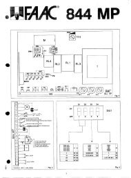
DESCRIPTION AND TECHNICAL SPECIFICATIONS<br />
Table 1: 410 MPS Control unit technical specifications<br />
Power supply 230 V(+6%-10%) - 50 Hz<br />
Absorbed power 10 W<br />
Max. motor load 800 W<br />
Max. accessories load 0,25 A<br />
Temperature range -20 °C +55 °C<br />
Fuses N. 3 (see fig.1)<br />
Operations logics Automatic / Semi-automatic / Safety /<br />
Automatic timer/ Step-by-step semi-automatic<br />
Opening/closing time Adjustable by trimmer (from 0-120 s)<br />
Pause time Adjustable by trimmer (from 0-240 s)<br />
Closing leaf de<strong>la</strong>y time Adjustable by trimmer (from 0 -28 s)<br />
Opening leaf de<strong>la</strong>y time 2.5 s (Can be disabled through bridge)<br />
Thrust force Adjustable by trimmer<br />
Terminal block inputs Open/Stop/Opening safeties/<br />
Closing safeties/ mains power +earth<br />
Terminal block outputs F<strong>la</strong>shing light - motors<br />
24 Vdc accessories power supply<br />
Quick connector Decoding cards - RP 433 SL/DS<br />
Microswitch programmable functions Operating logics<br />
Closing safeties logics<br />
J1<br />
1<br />
J2<br />
2 3 4 5 6 7 9 10<br />
N L<br />
LAMP<br />
OP COM CL<br />
MOTOR 1<br />
CL COM OP<br />
MOTOR 2<br />
230 V 50 Hz<br />
BLU<br />
M1<br />
C1<br />
J3<br />
8 11 12 13 14 15 16 17 18 19 20 21 22 23 24 25 26 27 28<br />
BLU<br />
M2<br />
N.B.: The capacitors are provided with the operators.<br />
Caution: Before touching the electronic unit (connections,<br />
programming, maintenance) always switch off the power<br />
supply.<br />
J1 terminal block (fig. 2)<br />
: Earth connection<br />
N. : power supply 230 V~ ( Neutre )<br />
L. : power supply 230 V~ ( Phase)<br />
N.B.: For correct operation the card must be connected to the<br />
system’s earth. Install a suitable differential magneto-thermal<br />
circuit-breaker upstream of the system.<br />
J2 terminal block (fig. 2)<br />
LAMP.: f<strong>la</strong>shing light output ( 230 V ~)<br />
MOTOR 1 Open /Common/ Close: Motor 1 connection<br />
Can be used in one-leaf application.<br />
(leaf closing de<strong>la</strong>y)<br />
MOTOR 2 Close /Common/ Open: Motor 2 connection<br />
Not to be used in one-leaf application.<br />
N.B. To check the operation of the equipment at the test<br />
bench, a load must be connected on the MOTOR 1 input.<br />
J3 terminal block: low voltage (fig. 2) used to connect all<br />
accessories (see table 2).<br />
30 Vdc<br />
– accessories power supply negative<br />
+ accessories power supply positive (+ 30 Vdc)<br />
C2<br />
+ — OP — CL NC —<br />
30 Vcc FSW STOP<br />
10<br />
LAYOUT AND ELECTRICAL WIRING<br />
J1<br />
F1<br />
N L<br />
J2 J3<br />
<br />
STOP<br />
A<br />
B — A — + — + —<br />
FSWTX W.LIGHT LOCK<br />
B<br />
OPEN<br />
TOT.<br />
<br />
FSW TX<br />
B<br />
Closing photocells<br />
F4<br />
<br />
F2<br />
<br />
<br />
A<br />
OPENING<br />
LEAF DELAY<br />
DISABLE<br />
DL4 DL5 DL2<br />
DL3<br />
FAILSAFE<br />
ON-OFF<br />
A<br />
<br />
Fig. 1<br />
For the safety and fail-safe devices, see the “Safety devices”<br />
section.<br />
Fig. 2<br />
Warning: the max. accessory load is 250 mA. To calcu<strong>la</strong>te<br />
absorption values, refer to table 2.<br />
Safety devices<br />
These are all devices (photocells, safety edges, magnetic<br />
coils, etc.) with an N.C. (normally closed) contact which<br />
activate if an obstacle obstructs the area protected by the<br />
Opening, closing or opening/closing photocells<br />
DL1<br />
<br />
Opening<br />
photocells<br />
Fig. 3
safety devices and stop the movement of the gate leaves<br />
(fig. 3).<br />
The 410 MPS card has an additional FAIL-SAFE device which<br />
serves to check that the N.C. contact on the photocell<br />
receiver is working efficiently before any operation(Can<br />
be disabled through bridge Fig. 1 ref.13) .<br />
N.B.: If the Opening safety devices are engaged when the<br />
gate is closed, they prevent the leaves from opening.<br />
If the Closing safety devices are engaged when the gate<br />
is open, they prevent the leaves from closing.<br />
OP. - Opening safety device contact (N.C.): in the A-S-E-EP-AD<br />
logics, during the opening phase the safety devices stop<br />
the movement of the gate leaves; when they are<br />
disengaged the opening movement recommences. They<br />
do not engage during closure.<br />
N.B.: If opening safety devices are not connected, jumper<br />
inputs OP and FSW TX (Fig. 4).<br />
11<br />
ENGLISH<br />
The purpose of the opening safety devices is to safeguard<br />
the zone behind the gate leaves (A, fig. 3).<br />
CL. - Closing safety device contact (N.C.): in the A-S-E-EP-AD<br />
logics, during the closing phase the safety devices reverse<br />
the direction of movement of the gate leaves, or they stop<br />
the movement of the leaves then reverse direction when<br />
they are disengaged (see microswitch SW4 settings). They<br />
do not engage during the opening cycle.<br />
N.B.: If closing safety devices are not connected, jumper<br />
inputs OP and FSWTX (fig. 4).<br />
The purpose of the closing safety devices is to safeguard<br />
the zone in which the leaves move during the closing cycle<br />
(B, fig. 3).<br />
If the Fail-Safe function is not used, see cabling at page 4<br />
for connections of photocells.<br />
Application examples<br />
The following are the commonly used connection arrangements (enable fail -safe):<br />
No safety device connected One pneumatic edge connected as closing safety device and<br />
14 15 16<br />
OP — CL<br />
FSW<br />
23 24<br />
+ —<br />
FSWTX<br />
one connected as opening safety device<br />
14 15 16<br />
23 24<br />
OP — CL<br />
+ —<br />
FSW<br />
FSWTX<br />
1 pair of closing photocells connected 1 pair of opening photocells connected<br />
12 13<br />
+ —<br />
30Vcc<br />
16<br />
OP — CL<br />
FSW<br />
1<br />
2<br />
3<br />
4<br />
5<br />
RX TX<br />
23<br />
+ —<br />
FSWTX<br />
14 15 24<br />
1 pair of opening photocells and 1 pair of closing<br />
photocells connected<br />
12 13 14 15 16<br />
23 24<br />
+ — OP — CL<br />
+ —<br />
30Vcc<br />
FSW<br />
FSWTX<br />
1<br />
2<br />
3<br />
4<br />
5<br />
1<br />
2<br />
1<br />
2<br />
RX CL TX CL<br />
TX OP<br />
RX OP<br />
1<br />
2<br />
1<br />
2<br />
3<br />
4<br />
5<br />
Fig. 4<br />
Fig. 6<br />
Fig. 8<br />
12 13 14 15 16<br />
23 24<br />
+ —<br />
30Vcc<br />
OP — CL<br />
FSW<br />
+ —<br />
FSWTX<br />
Important: for further information on the operation of the safety devices, see table 3.<br />
1<br />
2<br />
3<br />
4<br />
5<br />
RX TX<br />
Fig. 5<br />
1 pair of closing photocells and 1 pair of opening/closing<br />
photocells connected<br />
12 13 14 15 16<br />
23 24<br />
+ — OP — CL<br />
+ —<br />
30Vcc<br />
FSW<br />
FSWTX<br />
1<br />
2<br />
3<br />
4<br />
5<br />
1<br />
2<br />
1<br />
2<br />
RX CL TX CL<br />
TX OP<br />
RX OP<br />
1<br />
2<br />
1<br />
2<br />
3<br />
4<br />
5<br />
Fig. 7<br />
Fig. 9
ENGLISH<br />
14 15 16<br />
23 24<br />
12 13<br />
+ —<br />
30Vcc<br />
OP — CL<br />
FSW<br />
16<br />
OP — CL<br />
FSW<br />
1<br />
2<br />
3<br />
4<br />
5<br />
RX TX<br />
+ —<br />
FSWTX<br />
23<br />
+ —<br />
FSWTX<br />
14 15 24<br />
12 13 14 15 16<br />
23 24<br />
+ —<br />
30Vcc<br />
OP — CL<br />
FSW<br />
+ —<br />
FSWTX<br />
1<br />
2<br />
3<br />
4<br />
5<br />
1<br />
2<br />
Application examples<br />
The following are the commonly used connection arrangements (disable fail -safe)<br />
No safety device connected One pneumatic edge connected as closing safety device and<br />
one connected as opening safety device<br />
Two pair of closure photocells connected<br />
RX TX<br />
TX RX<br />
1<br />
2<br />
5<br />
4<br />
3<br />
2<br />
1<br />
1<br />
2<br />
12<br />
16<br />
OP — CL<br />
FSW<br />
23<br />
+ —<br />
FSWTX<br />
14 15 24<br />
Fig. 4/A Fig. 5/A<br />
1 pair of closing photocells connected 1 pair of opening photocells connected<br />
12 13 14 15 16<br />
23 24<br />
+ —<br />
30Vcc<br />
OP — CL<br />
FSW<br />
+ —<br />
FSWTX<br />
1<br />
2<br />
3<br />
4<br />
5<br />
1<br />
2<br />
3<br />
4<br />
5<br />
1<br />
2<br />
RX TX<br />
Fig. 6/A Fig. 7/A<br />
1 pair of closing photocells and 1 pair of opening/closing<br />
photocells connected<br />
12 13 14 15 16<br />
23 24<br />
+ —<br />
30Vcc<br />
OP — CL<br />
FSW<br />
+ —<br />
FSWTX<br />
RX TX<br />
TX<br />
Fig. 8/A Fig. 9/A<br />
RX<br />
1<br />
2<br />
1<br />
2<br />
5<br />
4<br />
3<br />
2<br />
1
STOP<br />
– Common ( - )<br />
N.C. - STOP contact: all devices (such as pushbuttons)<br />
which by opening a contact stop gate movement.<br />
To install several safety stop devices, connect the N.C.<br />
contacts in series.<br />
N.B. If the STOP devices are not connected, jumper STOP<br />
and - inputs.<br />
– Common ( - )<br />
A - TWO-LEAF OPENING (N.O.): all devices (pushbuttons ,<br />
photocells, detectors, etc.) which assures opening/closing<br />
of both leaves by closing a contact.<br />
To install several control devices, connect the N.O. contacts<br />
in parallel.<br />
FSWTX<br />
+ – Photocell transmitter power supply (FailSafe)<br />
To use the Fail-Safe function, power supplies to the photocell<br />
transmitters must be connected.<br />
J4 quick connector for decoder SL/DS - MINIDEC SL/DS - RP<br />
433 SL/DS cards (figs. 10-11-12-13)<br />
TORQUE trimmer: thrust adjusting trimmer (anti-crushing<br />
safety system).<br />
PAUSE trimmer: pause time adjusting trimmer (A/S AD/<br />
logics).<br />
Pause time is adjustable from 0 to 240 seconds.<br />
OP/CL trimmer: Opening/Closing time adjusting trimmer<br />
Time is adjustable from 0 to 120 seconds.<br />
LEAF DELAY trimmer: closing leaf de<strong>la</strong>y adjusting trimmer.<br />
Leaf de<strong>la</strong>y time is adjustable from 0 to 28 seconds.<br />
N.B.:<br />
1) If the opening/closing time is less than the set de<strong>la</strong>y<br />
time, the de<strong>la</strong>yed leaf closes at the end of the closing<br />
time.<br />
2) In one-leaf application, set the leaf de<strong>la</strong>y time to<br />
minimum<br />
Programming microswitches<br />
Fuse F1 5x20 5 A/250 V rapid (motor power supply)<br />
Fuse F2 5x20 800 mA/250 V de<strong>la</strong>yed (accessories power<br />
supply)<br />
Fuse F4 5x20 250 mA/250 V de<strong>la</strong>yed (transformer power<br />
supply)<br />
Bridge to enable/disable the Fail-Safe (Fig. 14).<br />
<br />
Bridge to enable/disable the wing opening<br />
de<strong>la</strong>y(Fig. 14).<br />
Table 2 - Current drawn by accessories<br />
ACCESSORY CURRENT DRAWN<br />
PLUS 40 SL 30 mA<br />
PLUS 433 E 20 mA<br />
MINIDEC SL / DS 6 mA<br />
DECODER SL / DS 20 mA / 55 mA<br />
RP 433 SL / DS 12 mA / 6 mA<br />
DIGICARD 15 mA<br />
METAL DIGIKEY 15 mA<br />
FOTOSWITCH 90 mA<br />
DETECTOR F4 / PS6 50 mA<br />
PHOTOBEAM 50 mA<br />
13<br />
410 MPS<br />
410 MPS<br />
PLUS<br />
433 E<br />
MINIDEC<br />
SL/DS<br />
410 MPS<br />
410 MPS<br />
ENGLISH<br />
DECODER<br />
SL<br />
Fig. 10 Fig. 11<br />
N.B. Use a dedicated decoder for other accessory types.<br />
Fig. 12<br />
Fig. 13
ENGLISH<br />
FAIL-SAFE<br />
LEAF DELAY<br />
1. PROGRAMMING THE MICROSWITCHES<br />
Automation programming is carried out by the microswitches<br />
(fig. 1 - ref. 9) as shown in the diagram below.<br />
OPERATING<br />
LOGICS<br />
A<br />
S<br />
E<br />
EP<br />
AD<br />
Disable<br />
Enable<br />
1 2 3 4<br />
1.1. OPERATION LOGICS<br />
There are four operating logics avai<strong>la</strong>ble:<br />
A : “AUTOMATIC ” E : “SEMI-AUTOMATIC”<br />
S : “SAFETY” EP : “SEMI-AUTOMATIC STEP-BY-STEP”<br />
AD: "AUTOMATIC TIMER"<br />
Operation of the different logics is described in tables 3/a-b-c-de.<br />
1.2. SAFETIES ON CLOSING<br />
This function serves to select the operating mode for the closing<br />
safeties:<br />
- OFF: immediate reverse of movement during gate closure<br />
- ON: movement is stopped during closing and reversed on<br />
opening when the safety is disengaged.<br />
2. START-UP<br />
1) Program the 410 MPS electronic control unit according to<br />
specific requirements as shown in fig. 15.<br />
2) Check led status as shown in table.<br />
LED functions<br />
LEDS ON OFF<br />
DL 1 (OPEN INPUT A) Command active Command not active<br />
DL 3 (STOP) Command not active Command active<br />
DL 4 (FTSW OPEN) Safeties disengaged Safeties engaged<br />
DL 5 (FTSW CLOSE) Safeties disengaged Safeties engaged<br />
N.B.: the bold text indicates led status with gate idle.<br />
Fig. 15<br />
SW1 SW2 SW3<br />
SAFETIES ON CLOSING SW4<br />
OFF OFF OFF<br />
ON OFF OFF<br />
OFF ON OFF<br />
ON ON OFF<br />
ON OFF ON<br />
Enable<br />
Disable<br />
INVERTS MOVEMENT<br />
IMMEDIATELY<br />
STOPS AND INVERTS<br />
MOVEMENT ON<br />
DISENGAGEMENT<br />
Fig. 14<br />
1)<br />
2.1. DIRECTION OF ROTATION<br />
Switch off the power.<br />
2) Manually move the gate to halfway.<br />
3) Lock the operators.<br />
4) Switch on the power.<br />
5) Send an OPEN signal to input A (fig. 2) and check that the<br />
leaf opens.<br />
OFF<br />
ON<br />
14<br />
If the gate closes, invert the motor wires on the control unit<br />
(brown and b<strong>la</strong>ck wires).<br />
2.2. OPERATION TIME ADJUSTMENT<br />
Opening/closing times are set by the OP/CL trimmer on the<br />
control unit (fig. 1 - ref.7).<br />
To reduce operation time, adjust the trimmer anticlockwise<br />
To increase operation time, adjust the trimmer clockwise.<br />
Maximum operation time is 120 seconds.<br />
For 90° opening the approximate opening/closing time is 18<br />
seconds.<br />
For optimal system efficiency set the opening/closing time so<br />
that the electric motor remains activated for a few seconds<br />
after the leaf has reached the mechanical travel stop.<br />
2.3. CLOSING LEAF DELAY ADJUSTMENT<br />
In the case of over<strong>la</strong>pping leaves, it is possible to de<strong>la</strong>y closing<br />
of the leaf driven by motor M1 (see fig. 2) to ensure correct<br />
closure of the gate.<br />
Set the de<strong>la</strong>y by the LEAF DELAY trimmer on the 410 MPS control<br />
unit (fig. 1 - ref. 8).<br />
To reduce de<strong>la</strong>y time, adjust the trimmer anticlockwise.<br />
To increase de<strong>la</strong>y time, adjust the trimmer clockwise.<br />
Maximum de<strong>la</strong>y time is 28 seconds. If the operation time is<br />
shorter, the de<strong>la</strong>y time is reduced automatically.<br />
2.4. SETTING PAUSE TIME<br />
When A, S or AD logics are selected, the leaf momentary stop<br />
time can be set using the PAUSE trimmer (fig. 1 ref. 6).<br />
Turn the trimmer clockwise to increase the time.<br />
Turn the trimmer anticlockwise to reduce the time.<br />
The maximum pause time is 240 sec.<br />
2.5. ANTI-CRUSHING SYSTEM ADJUSTMENT<br />
The 410 MPS control unit has been designed for use on both<br />
electromechanical and hydraulic operators.<br />
When the 410 MPS card is used on electromechanical operators,<br />
the torque control device must be set by turning the TORQUE<br />
trimmer (fig. 1 ref. 5).<br />
To reduce torque, adjust the trimmer anticlockwise.<br />
To increase torque, adjust the trimmer clockwise.<br />
In any event, FAAC advises not to exceed a torque of 15 Kg<br />
measured on the outer edge of the leaf.<br />
To ensure precise torque adjustment use a linear dynamometer.<br />
When the 410 MPS card is used on hydraulic operators, the<br />
torque control device must be set to the maximum value by<br />
turning the TORQUE trimmer clockwise.<br />
This device is already present inside the operator hydraulic<br />
circuit (BY-PASS valves).
(*1) If residual pause time is less than 5 seconds on safety disengagement, the gate closes after 5 seconds.<br />
N.B.: Effects of other active impulse inputs are shown in brackets<br />
Table 3/a<br />
LOGICS "A" PULSES<br />
GATE STATUS OPEN-A STOP<br />
OPENING SAFETIES<br />
CLOSING SAFETIES<br />
OPENING/CLOSING SAFETIES<br />
No effect (OPEN inhibited) No effect No effect (OPEN inhibited)<br />
Opens leaves and recloses after pause time<br />
CLOSED<br />
Freezes pause until disengagement (*1) (OPEN inhibited)<br />
No effect<br />
Recloses leaves immediately<br />
OPEN on PAUSE<br />
Stops closing and, when disengaged,<br />
opens<br />
See paragraph 1.2<br />
No effect (OPEN inhibited)<br />
Stops<br />
Reopens leaves immediately<br />
CLOSING<br />
Stops opening and, when disengaged,<br />
continues to open<br />
No effect<br />
Stops opening and, when disengaged,<br />
closes<br />
OPENING No effect<br />
No effect (OPEN inhibited)<br />
No effect<br />
No effect (OPEN inhibited)<br />
Closes leaf/leaves<br />
STOPPED<br />
Table 3/b<br />
LOGICS "S"<br />
PULSES<br />
GATE STATUS OPEN-A STOP<br />
OPENING SAFETIES<br />
CLOSING SAFETIES<br />
OPENING/CLOSING SAFETIES<br />
CLOSED Opens leaves and recloses after pause time<br />
No effect (OPEN inhibited) No effect<br />
No effect (OPEN inhibited)<br />
OPEN on PAUSE<br />
Recloses leaves immediately<br />
No effect<br />
Freezes pause until disengagement (*1) (OPEN inhibited)<br />
Stops closing and, when disengaged,<br />
CLOSING<br />
Reopens leaves immediately<br />
Stops<br />
No effect (OPEN inhibited) See paragraph 1.2<br />
opens<br />
Stops opening and, when disengaged,<br />
OPENING<br />
Recloses leaves immediately<br />
Stops opening and, when disengaged,<br />
No effect<br />
closes<br />
continues to open<br />
STOPPED Closes leaf/leaves No effect (OPEN inhibited)<br />
No effect No effect (OPEN inhibited)<br />
15<br />
Table 3/c<br />
LOGICS "E"<br />
PULSES<br />
GATE STATUS OPEN-A STOP<br />
OPENING SAFETIES<br />
CLOSING SAFETIES<br />
OPENING/CLOSING SAFETIES<br />
CLOSED Opens leaves No effect (OPEN inhibited) No effect No effect (OPEN inhibited)<br />
ENGLISH<br />
OPEN Recloses leaves immediately<br />
No effect<br />
No effect (OPEN inhibited)<br />
Stops closing and, when disengaged,<br />
CLOSING<br />
Reopens leaves immediately<br />
Stops<br />
No effect (OPEN inhibited)<br />
See paragraph 1.2<br />
opens<br />
Stops opening and, when disengaged,<br />
OPENING<br />
Stops<br />
Stops opening and, when disengaged,<br />
No effect<br />
continues to open<br />
closes<br />
STOPPED<br />
Closes leaf/leaves No effect (OPEN inhibited) No effect No effect (OPEN inhibited)
ENGLISH<br />
OPENING/CLOSING SAFETIES<br />
No effect (OPEN inhibited)<br />
Table 3/d<br />
LOGICS "EP" PULSES<br />
GATE STATUS OPEN-A<br />
STOP<br />
OPENING SAFETIES<br />
CLOSING SAFETIES<br />
CLOSED Opens leaves No effect (OPEN inhibited) No effect<br />
No effect (OPEN inhibited)<br />
Recloses leaf immediately<br />
OPEN<br />
Stops closing and, when disengaged,<br />
opens<br />
No effect<br />
See paragraph 1.2<br />
Stops<br />
Stops<br />
CLOSING<br />
Stops opening and, when disengaged,<br />
continues to open<br />
No effect<br />
Stops opening and, when disengaged,<br />
closes<br />
No effect<br />
(if the gate must open, inhibits OPEN)<br />
OPENING Stops<br />
No effect (OPEN inhibited)<br />
No effect<br />
(if gate must close, inhibits OPEN)<br />
No effect (OPEN inhibited)<br />
Inverts the direction<br />
STOPPED<br />
Table 3/e<br />
LOGICS "AD" PULSES<br />
GATE STATUS OPEN-A STOP<br />
OPENING SAFETIES<br />
CLOSING SAFETIES<br />
OPENING/CLOSING SAFETIES<br />
No effect (OPEN inhibited) No effect No effect (OPEN inhibited)<br />
Opens leaves and recloses after pause time<br />
CLOSED<br />
Freezes pause until disengagement (*1) (OPEN inhibited)<br />
No effect<br />
It controls the re-counting of the pause time<br />
OPEN on PAUSE<br />
Stops closing and, when disengaged,<br />
opens<br />
See paragraph 1.2<br />
No effect (OPEN inhibited)<br />
Stops<br />
Reopens leaves immediately<br />
CLOSING<br />
16<br />
Stops opening and, when disengaged,<br />
continues to open<br />
No effect<br />
Stops opening and, when disengaged,<br />
closes<br />
OPENING If held, it remains in pause (timer function).<br />
No effect (OPEN inhibited)<br />
No effect<br />
No effect (OPEN inhibited)<br />
Closes leaf/leaves<br />
STOPPED
Le descrizioni e le illustrazioni del presente manuale non sono impegnative. La FAAC si riserva il diritto,<br />
<strong>la</strong>sciando inalterate le caratter<strong>ist</strong>iche essenziali dell’apparecchiatura, di apportare in qualunque<br />
momento e senza impegnarsi ad aggiornare <strong>la</strong> presente pubblicazione, le modifiche che essa ritiene<br />
convenienti per miglioramenti tecnici o per qualsiasi altra esigenza di carattere costruttivo o<br />
commerciale.<br />
The descriptions and illustrations contained in the present manual are not binding. FAAC reserves the<br />
right, whilst leaving the main features of the equipments unaltered, to undertake any modifications<br />
it holds necessary for either technical or commercial reasons, at any time and without revising the<br />
present publication.<br />
Les descriptions et les illustrations du présent manuel sont fournies à titre indicatif. FAAC se réserve le<br />
droit d’apporter à tout moment les modifications qu’elle jugera utiles sur ce produit tout en conservant<br />
les caractér<strong>ist</strong>iques essentielles, sans devoir <strong>pour</strong> autant mettre à jour cette publication.<br />
Die Beschreibungen und Abbildungen in vorliegendem Handbuch sind unverbindlich. FAAC behält<br />
sich das Recht vor, ohne die wesentlichen Eigenschaften dieses Gerätes zu verändern und ohne<br />
Verbindlichkeiten in Bezug auf die Neufassung der vorliegenden Anleitungen, technisch bzw.<br />
konstruktiv/kommerziell bedingte Verbesserungen vorzunehmen.<br />
Las descripciones y <strong>la</strong>s ilustraciones de este manual no comportan compromiso alguno. FAAC se<br />
reserva el derecho, dejando inmutadas <strong>la</strong>s características esenciales de los aparatos, de aportar, en<br />
cualquier momento y sin comprometerse a poner al día <strong>la</strong> presente publicación, todas <strong>la</strong>s<br />
modificaciones que considere oportunas para el perfeccionamiento técnico o para cualquier otro<br />
tipo de exigencia de carácter constructivo o comercial.<br />
FAAC per <strong>la</strong> natura<br />
• La presente <strong>ist</strong>ruzione è realizzata al <strong>100%</strong> in carta ricic<strong>la</strong>ta.<br />
• Non disperdete nell'ambiente gli imbal<strong>la</strong>ggi dei componenti dell'automazione bensì selezionate<br />
i vari materiali (es. cartone, pol<strong>ist</strong>irolo) secondo prescrizioni locali per lo smaltimento rifiuti e le<br />
norme vigenti.<br />
FAAC for the environment<br />
• The present manual is produced in <strong>100%</strong> recycled paper<br />
• Respect the environment. Dispose of each type of product packaging material (card, polystyrene)<br />
in accordance with the provisions for waste disposal as specified in the country of instal<strong>la</strong>tion.<br />
FAAC der Umwelt zuliebe<br />
• Vorliegende Anleitungen sind auf <strong>100%</strong> <strong>Alt<strong>papier</strong></strong> gedruckt.<br />
• Verpackungsstoffe der Antriebskomponenten (z.B. Pappe, Styropor) nach den einschlägigen<br />
Normen der Abfallwirtschaft sortenrein sammeln.<br />
FAAC écologique<br />
• La présente notice a été réalisée <strong>100%</strong> avec du <strong>papier</strong> recyclé.<br />
• Ne pas jeter dans <strong>la</strong> <strong>nature</strong> les embal<strong>la</strong>ges des composants de l’automatisme, mais sélectionner<br />
les différents matériaux (ex.: carton, polystyrène) selon <strong>la</strong> légis<strong>la</strong>tion locale <strong>pour</strong> l’élimination des<br />
déchets et les normes en vigueur.<br />
FAAC por <strong>la</strong> naturaleza.<br />
• El presente manual de instrucciones se ha realizado, al <strong>100%</strong>, en papel recic<strong>la</strong>do.<br />
• Los materiales utilizados para el emba<strong>la</strong>je de <strong>la</strong>s d<strong>ist</strong>intas partes del s<strong>ist</strong>ema automático (cartón,<br />
poliestireno) no deben tirarse al medio ambiente, sino seleccionarse conforme a <strong>la</strong>s prescripciones<br />
locales y <strong>la</strong>s normas vigentes para el desecho de residuos sólidos.<br />
FAAC S.p.A.<br />
Via Benini, 1<br />
40069 Zo<strong>la</strong> Predosa (BO) - ITALIA<br />
Tel.: 051/6172411 - Tlx.: 521087<br />
Fax: 051/758518<br />
Timbro del Rivenditore:/D<strong>ist</strong>ributor’s Stamp:/Timbre de l’Agent:/ Fachhändlerstempel:/Sello del Revendedor:<br />
732259 - Rev. D - 11000 - 697 - M<br />
para <strong>la</strong> naturaleza<br />
<strong>100%</strong> papel recic<strong>la</strong>do<br />
<strong>ist</strong> <strong>umweltfreundlich</strong><br />
<strong>100%</strong> <strong>Alt<strong>papier</strong></strong><br />
<strong>pour</strong> <strong>la</strong> <strong>nature</strong><br />
<strong>papier</strong> recyclé <strong>100%</strong><br />
for <strong>nature</strong><br />
recycled paper <strong>100%</strong><br />
per <strong>la</strong> natura<br />
carta ricic<strong>la</strong>ta <strong>100%</strong>