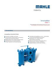
Duplex filter UG54 - MAHLE Industry - Filtration
Duplex filter UG54 - MAHLE Industry - Filtration
Duplex filter UG54 - MAHLE Industry - Filtration

You also want an ePaper? Increase the reach of your titles
YUMPU automatically turns print PDFs into web optimized ePapers that Google loves.
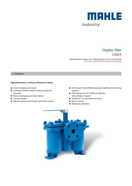
1. Features<br />
High-performance, continuous filtration for plants<br />
Used in shipping and industry<br />
Continuous filtration supports rational production<br />
processes<br />
Mature engineering and robust design<br />
Compact design<br />
Minimal pressure drop through optimal flow design<br />
<strong>Duplex</strong> <strong>filter</strong><br />
<strong>UG54</strong><br />
With stopcock change-over, rated pressure up to 10 bar (145 psi)<br />
Connection sizes: DN 20 to DN 80, cast design<br />
Elements with high differential pressure stability and dirt holding<br />
capacity<br />
Filter ratings from 25 to 5000 µm absolute,<br />
other ratings on request<br />
Suitable for use with fluids of all types<br />
Easy to service<br />
Worldwide distribution
-<br />
2. Operating principle<br />
The two bowls of the duplex <strong>filter</strong> are each fitted with a <strong>filter</strong> ele-<br />
ment (perforated, smooth or pleated) through which the medium<br />
flows from the inside to the outside.<br />
One <strong>filter</strong> bowl is pressurised during operation to allow the me-<br />
dium to flow through the <strong>filter</strong> element in the required direction.<br />
The <strong>filter</strong> changes over to the second bowl without interrupt-<br />
ing the filtration process when a settable fouling threshold is<br />
reached.<br />
The non-operational bowl can then be opened and the <strong>filter</strong> ele-<br />
ment removed for cleaning.<br />
<strong>Duplex</strong> <strong>filter</strong>s require no maintenance apart from cleaning the fil-<br />
ter elements and inspecting the seals.<br />
4. Dimensions<br />
All dimensions except "s" and "t" in mm.<br />
3. Technical Data<br />
Connection: DN 20 to DN 80<br />
Flange: DIN 2501 PN 16<br />
Material: Nodular cast iron 40<br />
Max. operating pressure: 10 bar<br />
Test overpressure: 15 bar<br />
Max. operating temperature: 120 °C<br />
Filter element: Screen basket<br />
Filter rating: 25 to 5000 µm absolute,<br />
other ratings on request<br />
<strong>Duplex</strong> <strong>filter</strong> <strong>UG54</strong> 2<br />
hallo<br />
t = Drain<br />
s = Vent<br />
Z = Clearance required<br />
*1 = Differential pressure indicator<br />
optional<br />
Type DN a b c d e Ø f g m h l Ø p s t Z<br />
Capacity<br />
[l]<br />
Weight<br />
CT093210A08 80 380 170 295 520 480 18.0 60 100 580 16 176 G1/4 G1 1/2 810 8.0 87<br />
CT083210A07 65 330 145 260 450 410 18.0 50 90 540 14 144 G1/4 G1 685 4.3 64<br />
CT073210A05 50 265 125 230 380 350 14.0 50 80 438 15 126 G1/4 G1 565 2.7 40<br />
CT063210A05 40 260 100 200 350 320 11.5 50 80 425 12 126 G1/4 G1 540 2.7 35<br />
CT053210A04 32 210 95 180 284 260 11.5 36 60 340 10 90 G1/8 G3/4 520 0.8 21<br />
CT043210A03 25 158 83 165 272 248 11.5 36 60 310 10 90 G1/8 G3/4 315 0.8 17<br />
CT033210A02 20 140 75 145 232 212 9.5 28 48 254 8 70 G1/8 G3/8 275 0.4 14<br />
[kg]
5. Design and application<br />
A wide range of <strong>filter</strong> elements are available for every duplex <strong>filter</strong>.<br />
The material, type of construction and <strong>filter</strong> surface and rating are<br />
expertly adapted to the specific filtration task based on the medium<br />
and capacity.<br />
Each duplex <strong>filter</strong> can be supplied with various options to ensure<br />
the optimum performance for each particular application.<br />
Options:<br />
Heating (steam/thermal oil, electric)<br />
Magnetic elements<br />
Differential pressure indicator/switch mounted on the <strong>filter</strong><br />
<strong>Duplex</strong> <strong>filter</strong>s are not at all complicated to use and they guarantee<br />
continuous filtration. The necessary steps are described in the fol-<br />
lowing:<br />
The <strong>filter</strong> comprises two bowls with a cover and a parallel unit.<br />
Each bowl contains a vent port, a drain port and a <strong>filter</strong> element.<br />
The <strong>filter</strong> must be filled and vented before it is put into service.<br />
Make sure the liquid flows through the <strong>filter</strong> in the direction indic-<br />
ated by the arrow, so that it enters the <strong>filter</strong> element at the top.<br />
Cylindrical elements are used for the filtration process. Impurities<br />
are trapped in the element and removed together with the latter<br />
when it is withdrawn from the housing for cleaning. The inside of<br />
the housing is permanently dirt-free as a result.<br />
The <strong>filter</strong> must be changed over and cleaned when a differential<br />
pressure of approx. 7 m/water column is reached. This is done<br />
by turning the spanner in the direction of the other bowl. The<br />
spanner should be applied according to the marking. The flow<br />
direction of the medium in the pressurised bowl is indicated by<br />
a marking on the stopcock spanner hub.<br />
If the <strong>filter</strong> has a pressure balance pipe, the valve for this pipe<br />
must be opened and closed again prior to changing over to the<br />
other bowl.<br />
After the <strong>filter</strong> has been changed over, the cover of the non-pres-<br />
surised bowl can be opened and the element lifted out vertically.<br />
To clean the <strong>filter</strong> element, either flush or blow it out or brush it<br />
with a soft brush. Carefully insert the cleaned element again ver-<br />
tically. When the cover is closed, the element is pressed against<br />
the support ring by means of the cover spring.<br />
The <strong>filter</strong> must be mounted without stress on flanges and feet.<br />
If the medium has a tendency to form deposits, the <strong>filter</strong> must<br />
not be allowed to run dry.<br />
If the change-over unit is stiff (because the medium has formed<br />
deposits), the stopcock must be switched once every day.<br />
In order to replace the O-rings, press the stopcock down so that<br />
the bottom ring can be removed, then pull it up to enable the top<br />
ring to be removed. Be careful not to adjust the stopcock any<br />
farther than is absolutely necessary to replace the O-rings.<br />
<strong>Duplex</strong> <strong>filter</strong> <strong>UG54</strong> 3
6. Type number key<br />
Type number key with selection example for <strong>UG54</strong> duplex <strong>filter</strong> DN 20 to DN 80<br />
Main product group<br />
C <strong>Duplex</strong> <strong>filter</strong>, cast design<br />
Series<br />
T <strong>Duplex</strong> flter with stopcock<br />
Inlet and outlet connections<br />
03 Flange DN 20<br />
04 Flange DN 25<br />
05 Flange DN 32<br />
06 Flange DN 40<br />
07 Flange DN 50<br />
08 Flange DN 65<br />
09 Flange DN 80<br />
Filter connection standard + rated pressure<br />
3 EN 1092 PN 16 bar<br />
Position of main connections<br />
2 Opposite each other on the same axis<br />
Cover fastening<br />
1 Stud bolts or hexagon screws<br />
Options<br />
0 Standard version<br />
2 Electric cartridge heater<br />
3 Steam/thermal cartridge heater<br />
7 Version without non-ferrous metals<br />
Type of inner assembly<br />
A Filter elements for simplex <strong>filter</strong><br />
Inner assembly size<br />
XX<br />
Housing version<br />
2 Nodular cast iron<br />
E Stainless steel<br />
Stopcock material<br />
C T 08 3 2 1 0 A 07 2 2 00<br />
-<br />
<strong>MAHLE</strong> Industriefiltration GmbH<br />
Hörn 14<br />
24220 Flintbek<br />
Phone +49 4347 904-0<br />
Fax +49 4347 904-120<br />
mahle.ako@mahle.com<br />
www.mahle-industrialfiltration.com<br />
70381744.03/2012<br />
2 Nodular cast iron<br />
Number for special types or design features<br />
<strong>Duplex</strong> <strong>filter</strong> <strong>UG54</strong> 4<br />
XX

![[PDF] MAHLE Powertrain â Company Overview - Mahle.com](https://img.yumpu.com/13696795/1/190x135/pdf-mahle-powertrain-a-company-overview-mahlecom.jpg?quality=85)