Ahoy!- Hosted by www.commodore.ca
Ahoy!- Hosted by www.commodore.ca
Ahoy!- Hosted by www.commodore.ca

Create successful ePaper yourself
Turn your PDF publications into a flip-book with our unique Google optimized e-Paper software.
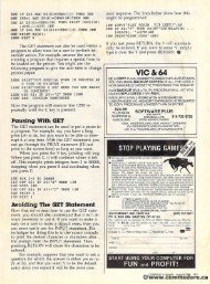
ounding components.<br />
Now Now we're we're ready ready to to solder. solder. Cut Cut<br />
your your hookup hookup wire wire into two two 9" 9"<br />
lengths, and and strip strip about about 'A" 'A" of of ininsulation from from all all four four ends. ends. I<br />
strongly suggest suggest "tinning" "tinning" the wire wire<br />
ends ends with with solder, since you'll be be<br />
working worlcing on an an extremely extremely small small<br />
area and flowing solder solder onto the the<br />
jumpers jumpers will will inevitably inevitably <strong>ca</strong>use <strong>ca</strong>use the the<br />
jumpers jumpers to to rebridge. Tinning Tinning the the<br />
wire makes it much simpler to<br />
touch touch the iron iron to to the the wire wire on on the<br />
jumper and create a bond. Solder<br />
one one end end of one one wire to to the the left left<br />
jumper jumper half half and one one end of of the the<br />
other other wire wire onto onto the the right right jumper<br />
half. Inspect your your work work to to make make<br />
sure that that solder solder hasn't hasn't rebridged rebridged<br />
the gap that that you you separated separated with with<br />
your knife. Once Once this this is is comcompletedpleted satisfactorily, you you may may then then<br />
proceed proceed to solder the the remaining remaining<br />
two wire ends ends to to the toggle toggle<br />
switch, each each wire going to to oppoopposite terminals on the switch. After<br />
completing completing this, this, it's it's a good good idea idea<br />
to try try the the drive drive out, out, just just to to make make<br />
sure sure that that everything's working'as worlcing as<br />
it it should. should. Be Be <strong>ca</strong>reful <strong>ca</strong>reful not not to touch touch<br />
any parts of the circuit board and<br />
keep your fingers out of the way.<br />
Plug in in the the power power cord cord and and the the<br />
serial serial connector connector from from your your VIC VIC<br />
or or C-64, C-64, tum tum on on the the drive drive and<br />
the the computer and and try to to load a<br />
disk-based disk-based program program in in the the usual usual<br />
manner. If the computer gives<br />
you you a "device not not present" present" error,<br />
try try flipping flipping the the switch and and loadloadinging again. again. If everything everything works works<br />
okay, then then you're you're all all set. Try Try to to<br />
load the the program program using using both both the the<br />
device device #8 #8 and and device device #9 <strong>ca</strong>lls, dependingpending<br />
on on the the position position of of the the<br />
switch. It It should should respond respond to to both<br />
numbers, numbers, depending depending on on how how the<br />
switch switch is positioned. If it's it's not not<br />
working worlcing in this this manner, in all<br />
probability probability you've allowed allowed some<br />
solder solder to to reconnect reconnect the the bridge bridge bebetweentween the the jumpers, jumpers, so so you'll you'll have have<br />
to to clean this up before<br />
proceeding. proceeding.<br />
Unplug Unplug the drive <strong>ca</strong>bles again, again,<br />
and and route route the wires wires across across the the<br />
printed printed circuit board (facing'the (facing the<br />
front front of of the the drive) drive) to to the left. Repositionposition<br />
the the metal metal cover cover and and ininstallstall the two two retaining retaining screws. screws.<br />
Tum the top cover of the drive<br />
over and and place place it it next next to the the drive drive<br />
on on the the left hand hand side. Insert the<br />
switch switch into the hold, hold , place the the<br />
washer and nut on the switch,<br />
and and tighten tighten securely. securely. Now Now gently<br />
tum the top top half over, place place it it on on<br />
the bottom half, invert the whole<br />
unit, and replace replace and and tighten tighten the the<br />
four four screws screws that that hold hold the the two two<br />
halves together. together. That's That's it!<br />
To To be on on the the safe safe side, reconnectnect<br />
the the power and and serial serial <strong>ca</strong>bles,<br />
tum turn on on the the computer computer and and the the<br />
drive, drive, and and boot boot a program program again, again,<br />
trying both the device #8 #8 and and device<br />
#9 <strong>ca</strong>lls. <strong>ca</strong>lls. It's a good good idea idea to to<br />
label the the switch switch positions positions so so that<br />
you'll know which position indi<strong>ca</strong>tes<br />
#8 and and which which indi<strong>ca</strong>tes #9.<br />
In most instances, when when you're you're<br />
using using two drives drives you'll find that<br />
it's best best to to tum tum the the power power on on to to<br />
the the computer first, drive drive #8 secsecond, and finally #9 third. For<br />
some some reason the VIC and and C-64<br />
sometimes have aa hard time telling<br />
how how many many peripherals peripherals are are<br />
hooked hooked up up to to it, and and this this method<br />
clears up the machine's "confusion."sion."<br />
In the the event that you're you're<br />
only only going going to to be using using one one drive,<br />
simply simply leave the the second drive drive<br />
turned off, and it will only a<strong>ca</strong>cknowledge device #8. But But at least<br />
now now you you have have the the flexibility flexibility of of<br />
choosing choosing your device # <strong>by</strong> <strong>by</strong> the<br />
simple flick flick of a switch! switch! 0D<br />
FIG.<br />
8S