80% A.F.U.E. UPFLOW/ HORIZONTAL GAS FURNACES
80% A.F.U.E. UPFLOW/ HORIZONTAL GAS FURNACES
80% A.F.U.E. UPFLOW/ HORIZONTAL GAS FURNACES

You also want an ePaper? Increase the reach of your titles
YUMPU automatically turns print PDFs into web optimized ePapers that Google loves.
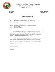
80PS- SERIES<br />
Models with Input Rates from<br />
50,000 to 150,000 BTU/HR<br />
[15 to 44 kW]<br />
ENER UIDE<br />
Annual Fuel Utilization Efficiency - AFUE<br />
THIS MODEL<br />
80.0%<br />
MID<br />
HIGH<br />
78% 82% 88% 97%<br />
FORM NO. G11-495<br />
Supersedes Form No. P66-765 Rev. 3<br />
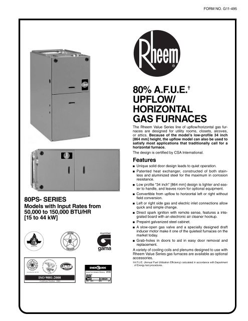
<strong>80%</strong> A.F.U.E. ✝<br />
<strong>UPFLOW</strong>/<br />
<strong>HORIZONTAL</strong><br />
<strong>GAS</strong> <strong>FURNACES</strong><br />
The Rheem Value Series line of upflow/horizontal gas furnaces<br />
are designed for utility rooms, closets, alcoves,<br />
or attics. Because of the model’s low-profile 34 inch<br />
[864 mm] height, the upflow model can also be used to<br />
satisfy most applications that traditionally call for a<br />
horizontal furnace.<br />
The design is certified by CSA International.<br />
Features<br />
■ Unique solid door design leads to quiet operation.<br />
■ Patented heat exchanger, constructed of both stainless<br />
and aluminized steel for the maximum in corrosion<br />
resistance.<br />
■ Low profile “34 inch” [864 mm] design is lighter and easier<br />
to handle, and leaves room for optional equipment.<br />
■ Convertible from upflow to horizontal left or right without<br />
field conversion.<br />
■ Left or right side gas and electric inlet connections allow<br />
quick and simple change.<br />
■ Direct spark ignition with remote sense, features a integrated<br />
board with an electronic air cleaner hookup.<br />
■ Prepaint galvanized steel cabinet.<br />
■ A slow-open gas valve and a specially designed draft<br />
inducer motor make it one of the quietest furnaces on the<br />
market today.<br />
■ Grab-holes in doors to aid in easy door removal and<br />
replacement.<br />
A variety of cooling coils and plenums designed to use with<br />
Rheem Value Series gas furnaces are available as optional<br />
accessories.<br />
✝A.F.U.E. (Annual Fuel Utilization Efficiency) calculated in accordance with Department<br />
of Energy test procedures.
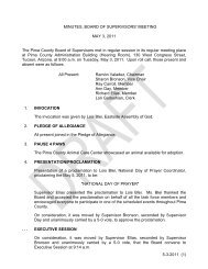
In-Shot Burners<br />
Integrated<br />
Furnace<br />
Control<br />
STANDARD EQUIPMENT<br />
Completely assembled and wired; induced draft; pressure switch; redundant main<br />
gas control; blower compartment door safety switch; solid state time on/time off<br />
blower control; limit control; manual shut-off valve, pressure regulator for natural<br />
and L.P. (propane) gas; transformer; direct drive multi-speed blower motor.<br />
Furnaces are equipped with cooling/heating relay and transformer (40VA) ready for<br />
air conditioning applications. (Please note: a thermostat is not included as standard<br />
equipment.) Flame sensor diagnostics.<br />
OPTIONAL EQUIPMENT<br />
Twinning Kit<br />
Side and bottom filter frame assembly. Return air cabinet for all sizes.<br />
NOTE: Furnace is not listed for use with fuels other than natural or L.P.<br />
(propane) gas.<br />
The complete terms of limited and other warranties are available at our sales<br />
office, or through local installer.<br />
2 ICECO<br />
RHEEM <strong>80%</strong> <strong>UPFLOW</strong>/<strong>HORIZONTAL</strong><br />
<strong>GAS</strong> FURNACE<br />
Patented Heat Exchanger<br />
Draft Inducer Motor<br />
Direct Spark Ignitor<br />
All models can be converted by a qualified Rheem distributor or local service dealer<br />
to use L.P. (propane) gas without changing burners. Factory approved kits must be<br />
used to convert from natural to L.P. (propane) gas and may be ordered as optional<br />
accessories from a Rheem parts distributor.<br />
For L.P. (propane) operation, refer to Conversion Kit Index Form.<br />
NOTE: For natural and L.P. (propane) gas models, standard hot surface ignition is<br />
100% safety lockout type.<br />
WARNING<br />
THIS FURNACE IS NOT APPROVED<br />
OR RECOMMENDED<br />
FOR USE IN MOBILE HOMES
BEFORE PURCHASING THIS APPLIANCE, READ IMPORTANT ENERGY COST AND EFFICIENCY INFORMATION AVAILABLE<br />
FROM YOUR RETAILER.<br />
PHYSICAL DATA AND SPECIFICATIONS<br />
MODEL NUMBERS<br />
80PS- SERIES<br />
05EAR**<br />
05NAR**<br />
07EBR**<br />
07NBR**<br />
07EER**<br />
07NER**<br />
10EBR** 10ECR**<br />
10EDR**<br />
10NDR**<br />
12EDR** 15EDR**<br />
Input-BTU/Hr [kW] ➁ 50,000 [15] 75,000 [22] 75,000 [22] 100,000 [29] 100,000 [29] 100,000 [29] 125,000 [37] 150,000 [44]<br />
Heating Capacity BTU/Hr [kW] ➀ 41,000 [12] 60,000 [18] 60,000 [18] 80,000 [23] 80,000 [23] 80,000 [23] 99,000 [29] 119,000 [35]<br />
Heat Ext. Static Pressure [kPa] .10 [.025] .12 [.029] .12 [.029] .15 [.037] .15 [.037] .15 [.037] .20 [.05] .20 [.05]<br />
Blower (D x W) [mm]<br />
Motor H.P.–Speed–<br />
PSC Type [W]<br />
11 x 6<br />
[279 x 152]<br />
1/2-4-PSC<br />
[373]<br />
11 x 7<br />
[279 x 178]<br />
1/2-3-PSC<br />
[373]<br />
11 x 7<br />
[279 x 178]<br />
1/2-3-PSC<br />
[373]<br />
11 x 7<br />
[279 x 178]<br />
1/2-3-PSC<br />
[373]<br />
11 x 10<br />
[279 x 254]<br />
1/2-3-PSC<br />
[373]<br />
11 x 10<br />
[279 x 254]<br />
3/4-3-PSC<br />
[560]<br />
11 x 10<br />
[279 x 254]<br />
3/4-3-PSC<br />
[560]<br />
11 x 10<br />
[279 x 254]<br />
3/4-3-PSC<br />
[560]<br />
Motor Full Load Amps 6.8 5.8 7.9 7.1 7.9 9.5 9.5 9.5<br />
Heating Speed Med-Low Med Med Med Med Low Low Low<br />
Cooling Speed High High High High High Med Med Med<br />
Cooling CFM @ .5" E.S.P.<br />
1200<br />
1200<br />
1600<br />
1200<br />
1845<br />
2060<br />
2115<br />
2080<br />
(Nominal) [L/s]<br />
[566]<br />
[566]<br />
[755]<br />
[566]<br />
[871]<br />
[922]<br />
[998]<br />
[982]<br />
Max. E.S.P. (In. W.C.) [kPa] 0.5 [.12] 0.5 [.12] 0.5 [.12] 0.5 [.12] 0.5 [.12] 0.5 [.12] 0.5 [.12] 0.5 [.12]<br />
Temperature Rise Range °F<br />
25-55<br />
35-65<br />
25-55<br />
45-75<br />
30-60<br />
30-60<br />
35-65<br />
50-80<br />
[°C]<br />
[13.9-30.6] [19.4-36.1] [13.9-30.6] [250-41.7] [16.7-33.3] [16.7-33.3] [19.4-36.1] [27.8-44.4]<br />
Max. Outlet Air Temp. °F<br />
155<br />
165<br />
155<br />
190<br />
170<br />
170<br />
180<br />
190<br />
[°C]<br />
[68.3]<br />
[73.8]<br />
[68.3]<br />
[87.7]<br />
[76.6]<br />
[76.6]<br />
[82.2]<br />
[87.7]<br />
Standard Filter (In.)<br />
15<br />
[mm]<br />
3/4 x 25 15<br />
[400 x 635]<br />
3/4 x 25 15<br />
[400 x 635]<br />
3/4 x 25 15<br />
[400 x 635]<br />
3/4 x 25 19<br />
[400 x 635]<br />
1/4 x 25 19<br />
[489 x 635]<br />
1/4 x 25 22<br />
[489 x 635]<br />
3/4 x 25 22<br />
[578 x 635]<br />
3/4<br />
Approx. Shipping Weight (Lbs.)<br />
85<br />
105<br />
105<br />
115<br />
120<br />
120<br />
140<br />
150<br />
[kg]<br />
[39]<br />
[48]<br />
[48]<br />
[52]<br />
[54]<br />
[54]<br />
[63]<br />
[68]<br />
x 25<br />
[578 x 635]<br />
Return Air Cabinets<br />
C14B<br />
C17B<br />
C17B<br />
C17B<br />
C21B<br />
C21B<br />
C24B<br />
C24B<br />
(Opt.) RXGR-<br />
(2) 12 x 16 (2) 12 x 16 (2) 12 x 16 (2) 12 x 16 (2) 20 x 16 (2) 20 x 16 (2) 24 x 16 (2) 24 x 16<br />
Filter Size [mm]<br />
[305 x 406] [305 x 406] [305 x 406] [305 x 406] [508 x 406] [508 x 406] [610 x 406] [610 x 406]<br />
AFUE–H.S.I. Models ➀ 80.0% 80.0% 80.0% 80.0% 80.0% 80.0% 80.0% 80.0%<br />
NOTES: All models are 115V, 60HZ, 1 Ph. Gas connection size for all models is 1/2" [12 mm] N.P.T.<br />
➀ In accordance with D.O.E. test procedures.<br />
➁ See Conversion Kit Index Form for high altitude derate.<br />
MODEL IDENTIFICATION—<strong>UPFLOW</strong>/<strong>HORIZONTAL</strong> MODELS<br />
80<br />
Efficiency<br />
P<br />
P = Upflow<br />
Non-Condensing<br />
[ ] Designates Metric Conversions<br />
S<br />
Design Series<br />
S = 3rd Design Series<br />
Electric Ignition<br />
05E/05N<br />
073/07N<br />
10E/10N<br />
12E<br />
15E<br />
05E<br />
Heating Input Designation<br />
Input BTU/HR [kW]<br />
50,000 [15]<br />
75,000 [22]<br />
100,000 [28]<br />
125,000 [37]<br />
150,000 [44]<br />
GENERAL TERMS OF LIMITED WARRANTY<br />
ICECO SM will furnish a replacement for any part of this product<br />
which fails in normal use and service within the applicable<br />
period stated, in accordance with the terms of the limited<br />
warranty.<br />
For Complete Details of the Limited Warranty, Including Applicable Terms<br />
and Conditions, See Your Local Installer or Contact the Manufacturer for<br />
a Copy.<br />
A<br />
Blower Designation [mm]<br />
A = Standard Cabinet<br />
11 x 6 [279 x 152]<br />
1/2 H.P. PSC<br />
B = Standard Cabinet<br />
11 x 7 [279 x 178]<br />
1/2 H.P. PSC/1200 CFM<br />
C = Wide Cabinet<br />
11 x 10 [279 x 254]<br />
1/2 H.P. PSC<br />
D = Standard Cabinet<br />
11 x 10 [279 x 254]<br />
3/4 H.P. PSC<br />
E = Standard Cabinet<br />
11 x 7 [279 x 178]<br />
1/2 H.P. PSC/1600 CFM<br />
R<br />
Fuel Designation<br />
R = Natural Gas - CSA -<br />
United States & Canada<br />
(North American)<br />
01<br />
Rheem<br />
Value Series<br />
Gas Heat Exchanger Limited Warranty ......Twenty (20) Years<br />
*Any Other Part.............................................Five (5) Years<br />
*This five year limited warranty is applicable only to single-phase products<br />
installed in residential applications on or after January 1, 2001.<br />
ICECO 3
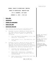
<strong>UPFLOW</strong> DIMENSIONS<br />
<strong>UPFLOW</strong> DIMENSIONS AND CLEARANCE TO COMBUSTIBLE MATERIAL (INCHES) [mm]<br />
MODEL<br />
80PS-<br />
A B C D E<br />
REDUCED CLEARANCE (IN.) [mm]<br />
07 171/2 [445] 1611/32 [415] 123/8 [314] ➀ 151/2 LEFT<br />
SIDE<br />
RIGHT<br />
SIDE<br />
BACK TOP FRONT VENT<br />
SHIP. WGTS.<br />
(LBS.) [Kg]<br />
05 14<br />
[381] 0 3 [76] ➁ 0 1 [25] 3 [76] 6 [152] ➂<br />
1/2 [356] 1227/32 [326] 105/8 [270] ➀ 111/2 [292] 0 4 [102] ➁ 0 1 [25] 3 [76] 6 [152] ➂ 85 [38.6]<br />
105 [47.6]<br />
10EB 171/2 [445] 1611/32 [415] 123/8 [314] ➀ 151/2 F<br />
2<br />
[381] 0 3 [76] ➁ 0 1 [25] 3 [76] 6 [152] ➂ 115 [52.2]<br />
1/2<br />
1<br />
[64]<br />
7/8 [48]<br />
21/2 [64]<br />
10EC & 10ED 211/2 [533] 1927/32 [504] 141/8 [359] ➀ 181/2 [470] 0 0 0 1 [25] 3 [76] 6 [152] ➂ 120 [54.4]<br />
12 241/2 [622] 2311/32 [593] 157/8 [403] ➀ 221/2 2<br />
[559] 0 0 0 1 [25] 3 [76] 6 [152] ➂ 140 [63.5]<br />
1/2 [64]<br />
21/2 [64]<br />
15 241/2 [622] 2311/32 [593] 157/8 [403] ➀ 221/2 [559] 2 0 0 0 1 [25] 3 [76] 6 [152] ➂<br />
1/2 [64]<br />
NOTES: ➀ May require a 3" [76 mm] to 4" [102 mm] or 3" [76 mm] to 5" [127 mm] adapter.<br />
➁ May be 0" [0 mm] with type B vent.<br />
➂ May be 1" [25 mm] with type B vent.<br />
Furnaces must be vented in accordance with the National Fuel Gas Code, ANSI Z223.1 and/or Can/CGA-B149 Installation Codes and in accordance with<br />
local codes.<br />
[ ] Designates Metric Conversions<br />
4 ICECO<br />
150 [68] .
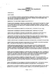
<strong>HORIZONTAL</strong> DIMENSIONS<br />
MODEL<br />
80PS-<br />
A B C D E<br />
REDUCED CLEARANCE (IN.) [mm]<br />
07 171/2 [445] 1611/32 [415] 123/8 [314] ➀ 151/2 LEFT<br />
SIDE<br />
RIGHT<br />
SIDE<br />
BACK TOP FRONT VENT<br />
SHIP. WGTS.<br />
(LBS.) [Kg]<br />
05 14<br />
[381] 0 3 [76] ➁ 0 1 [25] 3 [76] 6 [152] ➂<br />
1/2 [356] 1227/32 [326] 105/8 [270] ➀ 111/2 [292] 0 4 [102] ➁ 0 1 [25] 3 [76] 6 [152] ➂ 85 [38.6]<br />
105 [47.6]<br />
10EB 171/2 [445] 1611/32 [415] 123/8 [314] ➀ 151/2 F<br />
2<br />
[381] 0 3 [76] ➁ 0 1 [25] 3 [76] 6 [152] ➂ 115 [52.2]<br />
1/2<br />
1<br />
[64]<br />
7/8 [48]<br />
21/2 [64]<br />
10EC & 10ED 211/2 [533] 1927/32 [504] 141/8 [359] ➀ 181/2 [470] 0 0 0 1 [25] 3 [76] 6 [152] ➂ 120 [54.4]<br />
12 241/2 [622] 2311/32 [593] 157/8 [403] ➀ 221/2 2<br />
[559] 0 0 0 1 [25] 3 [76] 6 [152] ➂ 140 [63.5]<br />
1/2 [64]<br />
21/2 [64]<br />
15 241/2 [622] 2311/32 [593] 157/8 [403] ➀ 221/2 [559] 2 0 0 0 1 [25] 3 [76] 6 [152] ➂<br />
1/2 [64]<br />
NOTES: ➀ May require a 3" [76 mm] to 4" [102 mm] or 3" [76 mm] to 5" [127 mm] adapter.<br />
➁ May be 0" [0 mm] with type B vent.<br />
➂ May be 1" [25 mm] with type B vent.<br />
Furnaces must be vented in accordance with the National Fuel Gas Code, ANSI Z223.1 and/or Can/CGA-B149 Installation Codes and in accordance with<br />
local codes.<br />
[ ] Designates Metric Conversions<br />
WARNING<br />
THIS FURNACE IS NOT APPROVED<br />
OR RECOMMENDED FOR <strong>HORIZONTAL</strong><br />
APPLICATION OR INSTALLATION<br />
ON ITS BACK, WITH ACCESS DOORS<br />
FACING UPWARDS.<br />
<strong>HORIZONTAL</strong> DIMENSIONS AND CLEARANCE TO COMBUSTIBLE MATERIAL (INCHES) [mm]<br />
150 [68] .<br />
ICECO 5
ACCESSORIES—<strong>UPFLOW</strong><br />
INTERNAL FILTER RACK FOR BOTTOM<br />
OR SIDE RETURN: RXGF-DA*<br />
Each order contains (1) one box of 10 filter racks supplied<br />
without filters.<br />
*Filters available through PROSTOCK ® .<br />
SIDE RETURN FILTER RACK: RXGF-CA<br />
BOTTOM RETURN FILTER RACK FOR<br />
<strong>UPFLOW</strong> APPLICATION: RXGF-CB<br />
6 ICECO<br />
FILTER RACK FILTER SIZES† INCHES [mm]<br />
MODEL<br />
80PS-<br />
05, 07, 10EB (3 Ton)<br />
10EC & 10ED<br />
12, 15<br />
†Filter racks are shipped without filters.<br />
A 1" [25.4 mm] filter may be used.<br />
*Designates “E” or “N”.<br />
THE RXGR-C24B MUST ONLY BE INSTALLED ON THE SIDE<br />
OPPOSITE THE <strong>GAS</strong> AND ELECTRICAL CONNECTIONS.<br />
RXGF-CA<br />
(SIDE)<br />
153/4 x 25<br />
[400 x 635]<br />
153/4 x 25<br />
[400 x 635]<br />
153/4 x 25<br />
[400 x 635]<br />
RXPF-F01 and F02<br />
FOSSIL FUEL KIT—is for use with Rheem Value Series Heat<br />
Pumps and air furnaces. RXPF-F02 meets TVA requirements.<br />
RXGP-F03<br />
TWINNING KIT—is for parallel operation requirements.<br />
ACCESSORY RETURN<br />
AIR CABINETS<br />
Return Air Cabinets may<br />
be installed on either side<br />
application except RXGR-C24B<br />
(side application must be<br />
on side opposite gas and electrical<br />
connections).<br />
RETURN AIR CABINETS<br />
A<br />
IN. [mm]<br />
FILTER SIZE<br />
IN. [mm]<br />
RXGR-C14B 14 1/4 [356] (2) 12 x 16 [305 x 406]<br />
RXGR-C17B 17 1/2 [445] (2) 12 x 16 [305 x 406]<br />
RXGR-C21B 21 1/4 [533] (2) 20 x 16 [508 x 406]<br />
RXGR-C24B 24 1/2 [622] (2) 24 x 16 [610 x 406]<br />
WARNING: IMPORTANT NOTICE<br />
A SOLID METAL BASE PLATE (SEE TABLE) MUST BE IN PLACE WHEN THE FURNACE<br />
IS INSTALLED WITH SIDE AIR RETURN DUCTS. FAILURE TO INSTALL A BASE PLATE<br />
COULD CAUSE PRODUCTS OF COMBUSTION TO BE CIRCULATED INTO THE LIVING<br />
SPACE AND CREATE POTENTIALLY HAZARDOUS CONDITIONS.<br />
FURNACE<br />
WIDTH<br />
IN. [mm]<br />
SOLID BOTTOM<br />
KIT NO.<br />
BASE<br />
PLATE NO.<br />
BASE<br />
PLATE SIZE<br />
IN. [mm]<br />
141/2 [356] RXGB-D14 AE-61874-01 115/8 x 239/16 [295 x 598]<br />
171/2 [445] RXGB-D17 AE-61874-02 151/8 x 239/16 [384 x 598]<br />
211/2 [533] RXGB-D21 AE-61874-03 185/8 x 239/16 [473 x 598]<br />
241/2 [622] RXGB-D24 AE-61874-04 255/8 x 239/16 [651 x 598]<br />
FOR HIGH ALTITUDES:<br />
HIGH ALTITUDE OPTION CODE: U.S. & Canada –<br />
None required for high altitudes.<br />
HIGH ALTITUDE CONVERSION KITS: U.S. & Canada –<br />
None required for high altitudes.<br />
80+ HIGH ALTITUDE INSTRUCTIONS<br />
CAUTION: Always follow National Fuel Gas Code (NFGC) guidelines<br />
when converting for high altitudes.<br />
High altitude option codes are not required for these models.<br />
However, the burner orifice size needs to be recalculated and<br />
verified at elevations above 2000 ft. See Installation Instructions for<br />
more information.<br />
NOTE: For Canadian installations only, an optional derate (manifold<br />
gas pressure reduction) method may be used to adjust the<br />
furnace for altitude. See Installation Instructions for more<br />
information. This optional method may NOT be used for U.S.<br />
installations.<br />
[ ] Designates Metric Conversions
BLOWER PERFORMANCE DATA—<strong>UPFLOW</strong> MODELS<br />
MODEL<br />
NUMBER<br />
80PS-<br />
SERIES<br />
05EAR**<br />
05NAR**<br />
07EBR**<br />
07NBR**<br />
07EER**<br />
07NER**<br />
10EBR**<br />
10ECR**<br />
10EDR**<br />
10NDR**<br />
12EDR**<br />
15EDR**<br />
BLOWER<br />
SIZE<br />
[mm]<br />
11 x 6<br />
[279 x 152]<br />
11 x 7<br />
[279 x 178]<br />
11 x 7<br />
[279 x 178]<br />
11 x 7<br />
[279 x 178]<br />
11 x 10<br />
[279 x 254]<br />
11 x 10<br />
[279 x 254]<br />
11 x 10<br />
[279 x 254]<br />
11 x 10<br />
[279 x 254]<br />
MOTOR<br />
H.P.<br />
[W]<br />
1/2<br />
[373]<br />
1/2<br />
[373]<br />
1/2<br />
[373]<br />
1/2<br />
[373]<br />
1/2<br />
[373]<br />
3/4<br />
[559]<br />
3/4<br />
[559]<br />
3/4<br />
[559]<br />
Note: Recommended blower speeds are in bold.<br />
[ ] Designates Metric Conversions<br />
BLOWER<br />
SPEED<br />
LOW<br />
MED-LO<br />
MED-HI<br />
HIGH<br />
LOW<br />
MED<br />
HIGH<br />
LOW<br />
MED<br />
HIGH<br />
LOW<br />
MED<br />
HIGH<br />
LOW<br />
MED<br />
HIGH<br />
LOW<br />
MED<br />
HIGH<br />
LOW<br />
MED<br />
HIGH<br />
LOW<br />
MED<br />
HIGH<br />
675 [319]<br />
950 [448]<br />
1115 [526]<br />
1270 [599]<br />
1093 [563]<br />
1241 [586]<br />
1393 [657]<br />
1245 [588]<br />
1555 [734]<br />
1810 [854]<br />
1050 [496]<br />
1220 [576]<br />
1410 [665]<br />
1295 [611]<br />
1645 [776]<br />
2045 [965]<br />
1645 [776]<br />
2045 [965]<br />
2320 [1095]<br />
1645 [776]<br />
2050 [967]<br />
2365 [1116]<br />
1620 [765]<br />
2010 [949]<br />
2340 [1104]<br />
CFM [L/s] AIR DELIVERY<br />
EXTERNAL STATIC PRESSURE INCHES [kPa] WATER COLUMN<br />
.1 [.02] .2 [.05] .3 [.07] .4 [.10] .5 [.12] .6 [.15] .7 [.17]<br />
655 [309]<br />
930 [439]<br />
1090 [514]<br />
1250 [590]<br />
1066 [503]<br />
1212 [572]<br />
1359 [642]<br />
1220 [576]<br />
1515 [715]<br />
1755 [828]<br />
1040 [491]<br />
1195 [564]<br />
1380 [651]<br />
1275 [602]<br />
1615 [762]<br />
2000 [944]<br />
1615 [762]<br />
2000 [944]<br />
2260 [1067]<br />
1635 [772]<br />
2015 [951]<br />
2310 [1090]<br />
1595 [753]<br />
1985 [937]<br />
2275 [1074]<br />
635 [300]<br />
905 [427]<br />
1070 [505]<br />
1225 [578]<br />
1039 [490]<br />
1183 [558]<br />
1326 [626]<br />
1195 [564]<br />
1475 [696]<br />
1705 [805]<br />
1030 [486]<br />
1160 [547]<br />
1345 [635]<br />
1250 [590]<br />
1580 [746]<br />
1955 [923]<br />
1580 [746]<br />
1955 [923]<br />
2200 [1038]<br />
1615 [762]<br />
1980 [934]<br />
2250 [1062]<br />
1570 [741]<br />
1960 [925]<br />
2215 [1045]<br />
610 [288]<br />
880 [415]<br />
1040 [491]<br />
1200 [566]<br />
1008 [476]<br />
1150 [543]<br />
1293 [610]<br />
1165 [550]<br />
1435 [677]<br />
1645 [776]<br />
990 [467]<br />
1140 [538]<br />
1300 [614]<br />
1225 [578]<br />
1550 [732]<br />
1905 [899]<br />
1550 [732]<br />
1905 [899]<br />
2130 [1005]<br />
1590 [750]<br />
1935 [913]<br />
2185 [1031]<br />
1545 [729]<br />
1915 [904]<br />
2145 [1012]<br />
585 [276]<br />
860 [406]<br />
1015 [479]<br />
1165 [550]<br />
977 [461]<br />
1118 [528]<br />
1259 [594]<br />
1135 [536]<br />
1395 [658]<br />
1585 [748]<br />
960 [453]<br />
1105 [522]<br />
1255 [592]<br />
1195 [564]<br />
1510 [713]<br />
1845 [871]<br />
1510 [713]<br />
1845 [871]<br />
2060 [972]<br />
1560 [736]<br />
1885 [890]<br />
2115 [998]<br />
1515 [715]<br />
1850 [873]<br />
2080 [982]<br />
555 [262]<br />
830 [392]<br />
985 [465]<br />
1130 [533]<br />
941 [444]<br />
1076 [508]<br />
1214 [573]<br />
1105 [522]<br />
1350 [637]<br />
1530 [722]<br />
920 [434]<br />
1065 [503]<br />
1205 [569]<br />
1165 [550]<br />
1465 [691]<br />
1785 [842]<br />
1465 [691]<br />
1785 [842]<br />
1985 [937]<br />
1520 [717]<br />
1835 [866]<br />
2035 [960]<br />
1480 [698]<br />
1800 [850]<br />
2010 [949]<br />
520 [245]<br />
800 [380]<br />
945 [446]<br />
1085 [512]<br />
905 [427]<br />
1033 [487]<br />
1169 [552]<br />
1065 [503]<br />
1300 [614]<br />
1470 [694]<br />
890 [420]<br />
1020 [481]<br />
1150 [543]<br />
1135 [536]<br />
1425 [673]<br />
1720 [812]<br />
1425 [673]<br />
1720 [812]<br />
1910 [901]<br />
1470 [694]<br />
1775 [838]<br />
1950 [920]<br />
1440 [680]<br />
1730 [816]<br />
1940 [916]<br />
ICECO 7
Before proceeding with installation, refer<br />
to installation instructions packaged<br />
with each model, as well as complying<br />
with all Federal, State, Provincial, and<br />
Local codes, regulations, and practices.<br />
RHEEM<br />
AIR CONDITIONING<br />
DIVISION<br />
5600 Old Greenwood Road, Fort Smith, Arkansas 72908<br />
“In keeping with its policy of continuous progress and product improvement, ICECO reserves the right to make changes without notice.”<br />
PRINTED IN U.S.A. 3-07 DC FORM NO. G11-495<br />
Supersedes Form No. A11-182 Rev. 4
Mobile Home Gas Furnaces<br />
The Great Indoors has never felt this good<br />
Coleman Mobile Home Gas Furnaces are available in<br />
different configurations as follows:<br />
DGAA-BDTB - Series features auto hot surface ignition in "tall"<br />
cabinet (with coil cavity), up to 4-ton air conditioning ready - two<br />
speed blower operation.<br />
DGAH-BBSB - Series features auto hot surface ignition in "shorty"<br />
cabinet (without coil cavity) up to 3 ton air conditioning ready - single<br />
speed blower operation.<br />
Additional Features:<br />
• Available in two height sizes: the "Shorty" is 591/2 inches<br />
high and "Tall" is 76 inches high.<br />
• Aluminized steel “Tubular” Heat Exchanger design, for more even<br />
heat distribution and longer life.<br />
• Attractive white stylish contoured doors are very durable and<br />
scratch resistant.<br />
• Universal disposal filters clean the air and are easy to replace.<br />
• Adjustable, one step wedgeless roof jack accessory.<br />
• 2 year parts and 10 year heat exchanger limited warranties.<br />
DGAA-BDTB & DGAH-BBSB Series<br />
The Indoor Outfitters <br />
Natural Gas to Propane<br />
Gas Convertible
Duct Connector Dimensions<br />
Duct Connector Duct Connector<br />
Part Number Depth<br />
7990-6211 1”<br />
7990-6221 2”<br />
7990-6241 4-1/2”<br />
7990-6261 6-1/2”<br />
7990-6271 7-1/2”<br />
7990-6281 8-1/2”<br />
7990-6301 10-1/4”<br />
7990-6321 12-1/4”<br />
Duct Connectors for Tab Attachment<br />
System Specifications<br />
MODEL NO. DGAH056BBSB DGAH077BBSB DGAA056BDTB DGAA070BDTB DGAA077BDTB DGAA090BDTB<br />
Input-BTUH 56,000 77,000 56,000 70,000 77,000 90,000<br />
Output - BTUH 45,000 62,000 45,000 56,000 62,000 72,000<br />
AF U E <strong>80%</strong> <strong>80%</strong> <strong>80%</strong> <strong>80%</strong> <strong>80%</strong> <strong>80%</strong><br />
SPEED 1 1 2 2 2 2<br />
H.P. 1/6 1/6 1/3 1/3 1/3 1/3<br />
Fuse or Circuit 15 AMP Maximum<br />
Breaker<br />
E.S.P. 0.3 0.3 0.3 0.3 0.3 0.3<br />
Air Del-CFM 1055 1055 1145/1305 1145/1305 1145/1305 1145/1305<br />
Filters Two 16" x 20" x 1"<br />
Cabinet cm 146.02 H x 49.53W x 60.96D 193.04H x 49.53 W x 60.96 D<br />
Dimensions ins. 59.5 H x 19.5W x 24.0 D 76.0 H x 19.5 W x 24.0 D<br />
Weight 66.2 kg. (146 lbs.) 66.2 kg. (146 lbs.) 73.9 kg. (163 lbs.) 73.9 kg. (163 lbs.) 73.9 kg. (163 lbs.) 73.9 kg. (163 lbs.)<br />
AUTHORIZED COLEMAN DEALER<br />
Coleman and the Coleman logo are registered trademarks of The Coleman Company, Inc., used<br />
under license. Manufactured by Johnson Controls Company. www.colemanac.com.<br />
© 2006 The Coleman Company, Inc. All rights reserved. Subject to change without notice.<br />
CMGF - November, 06<br />
Roof Jack Table<br />
“Shorty” Model “Tall” Model<br />
Swivel Flashing DGAH Furnaces DGAA Furnaces<br />
Adjusts from Installation Dimensions Installation Dimensions<br />
0/12 TO 5/12 Pitch "A" Adjustable Heigth "B" Adjustable Heigth<br />
4000-7101/C 70" to 79" 86 to 95"<br />
4000-7121 /C 75" to 86" 91 " to 102"<br />
4000-7141/C 83" to 104" 99" to 120"<br />
4000-7151/C 90" to 116" 106" to132"<br />
4000-7171/C 127" to157" 143" to 173"<br />
2323 Winston Park Drive<br />
Oakville, ON L6H 6R7<br />
Phone: (905) 829-1411<br />
2307 Centre Ave. S.E.<br />
Calgary, Alberta T2E 0A9<br />
Phone: (403) 235-5454
TECHNICAL<br />
SPECIFICATIONS<br />
M1 Series Furnaces<br />
M1G* Standing Pilot<br />
M1M* Hot Surface Ignition<br />
M1S* Oil Gun<br />
M1B* Gas Gun<br />
The M1 Series furnace is designed for all sizes of manufactured<br />
and modular homes. These units incorporate high<br />
effi ciency, reliability, and low maintenance. Units may be<br />
installed free standing in a utility room or enclosed in an<br />
alcove or closet. M1 Series furnaces are available in A/C<br />
adaptable or A/C ready, with or without coil cavity box,<br />
multiple blower combinations for cooling requirements, and<br />
many burner options.<br />
Features and Benefi ts<br />
• Sealed Combustion System<br />
Vents exhaust gas directly outdoors and draws in<br />
100% outside air for the burner.<br />
• Easy Open Pawl Latch<br />
Secures the door fi rmly for transit, yet allows easy<br />
removal for access.<br />
• Choice of Air Conditioning Options<br />
From 2 to 5 tons A/C ready.<br />
• Large, Effective Air Filter<br />
Room air is cleaner with this permanent washable<br />
fi lter.<br />
• High Effi ciency Drum Heat Exchanger<br />
Delivers optimum heat transfer with low air resistance.<br />
• Appliance Quality Door<br />
Protects against rust and other corrosion. Baked<br />
enamel fi nish allows for easy cleaning.<br />
• Fully Insulated Cabinet<br />
Insures minimized heat loss and quiet operation.<br />
• Reliable Burner<br />
With uniform fl ame pattern extends life of heat exchanger.<br />
• Ventilation Switch<br />
Conveniently located in the door (heat only models).
MODEL IDENTIFICATION<br />
SPECIFICATIONS<br />
2<br />
Application<br />
M-Manufactured Home<br />
Furnace Series<br />
Fuel, Type of Combustion<br />
G-Gas, Direct Vent, Pilot Burner<br />
Natural or Forced Draft<br />
M-Gas, Direct Vent, HSI, Forced Draft<br />
B-Gas, Direct Vent, Gun Burner<br />
S-Oil, Direct Vent, Gun Burner<br />
Comfort Model<br />
H - Heating<br />
A - Heating, A/C Ready<br />
B - A/C Ready, 3 Ton<br />
C - A/C Ready, 4 Ton<br />
D - A/C Ready, 5 Ton<br />
M 1 M B - 056 A - B W<br />
Door Color<br />
W - White<br />
Cabinet Dimensions<br />
A - 56" x 19-3/4" x 23-3/4”<br />
B - w/Coil Cavity, 76" x 19-3/4" x 23-3/4"<br />
Electrical Code<br />
A - 1PH, 60 Hz, 120 VAC<br />
Heating Capacity<br />
Input, BTUH (000’)<br />
Furnace Input Output Orifi ce No E.S.P. Pilot Ignitor Comb. Motor<br />
A/C Ready AFUE % Shipping Weight<br />
Model No MBtu/h MBtu/h Nat. LP In WC Burner Direct Blower Hp FLA Tons Nat / LP A Cabinet B Cabinet<br />
M1GH 056 56 45 29 45 0.2 x 1/8 6.3 2*<br />
146 161<br />
M1GB 056<br />
M1GC 056<br />
56<br />
56<br />
45<br />
45<br />
29<br />
29<br />
45<br />
45<br />
0.3<br />
0.3<br />
x<br />
x<br />
1/4<br />
1/2<br />
6<br />
7.9<br />
3<br />
4<br />
75<br />
151<br />
155<br />
166<br />
170<br />
M1GD 056 56 45 29 45 0.3 x 3/4 11 5 157 172<br />
M1GH 070 70 57 24 42 0.3 x 1/5 5 2½*<br />
148 163<br />
M1GB 070<br />
M1GC 070<br />
70<br />
70<br />
57<br />
57<br />
24<br />
24<br />
42<br />
42<br />
0.3<br />
0.3<br />
x<br />
x<br />
1/4<br />
1/2<br />
6<br />
7.9<br />
3<br />
4<br />
75<br />
152<br />
156<br />
167<br />
171<br />
M1GD 070 70 57 24 42 0.3 x 3/4 11 5 158 173<br />
M1GH 077 77 60 21 40 0.3 x x 1/4 6 3*<br />
147 162<br />
M1GB 077<br />
M1GC 077<br />
77<br />
77<br />
60<br />
60<br />
21<br />
21<br />
40<br />
40<br />
0.3<br />
0.3<br />
x<br />
x<br />
x<br />
x<br />
1/4<br />
1/2<br />
6<br />
7.9<br />
3<br />
4<br />
75<br />
148<br />
155<br />
163<br />
170<br />
M1GD 077 77 60 21 40 0.3 x x 3/4 11 5 157 172<br />
M1GH 090 90 70 17 36 0.3 x x 1/4 6 3*<br />
149 164<br />
M1GB 090<br />
M1GC 090<br />
90<br />
90<br />
70<br />
70<br />
17<br />
17<br />
36<br />
36<br />
0.3<br />
0.3<br />
x<br />
x<br />
x<br />
x<br />
1/4<br />
1/2<br />
6<br />
7.9<br />
3<br />
4<br />
75<br />
150<br />
155<br />
165<br />
170<br />
M1GD 090 90 70 17 36 0.3 x x 3/4 11 5 157 172<br />
M1MA 056 56 46 29 45 0.2 x x 1/8 6.3 2<br />
147 162<br />
M1MB 056<br />
M1MC 056<br />
56<br />
56<br />
46<br />
46<br />
29<br />
29<br />
45<br />
45<br />
0.3<br />
0.3<br />
x<br />
x<br />
x<br />
x<br />
1/4<br />
1/2<br />
6<br />
7.9<br />
3<br />
4<br />
80<br />
152<br />
156<br />
167<br />
171<br />
M1MD 056 56 46 29 45 0.3 x x 3/4 11 5 158 173<br />
M1MA 070 70 57 24 42 0.3 x x 1/5 5 2½<br />
149 164<br />
M1MB 070<br />
M1MC 070<br />
70<br />
70<br />
57<br />
57<br />
24<br />
24<br />
42<br />
42<br />
0.3<br />
0.3<br />
x<br />
x<br />
x<br />
x<br />
1/4<br />
1/2<br />
6<br />
7.9<br />
3<br />
4<br />
80<br />
153<br />
157<br />
168<br />
172<br />
M1MD 070 70 57 24 42 0.3 x x 3/4 11 5 158 173<br />
M1MB 077 77 62 21 40 0.3 x x 1/4 6 3<br />
149 164<br />
M1MC 077 77 62 21 40 0.3 x x 1/2 7.9 4 80<br />
156 171<br />
M1MD 077 77 62 21 40 0.3 x x 3/4 11 5 158 173<br />
M1MB 090 90 72 17 36 0.3 x x 1/4 6 3<br />
151 166<br />
M1MC 090 90 72 17 36 0.3 x x 1/2 7.9 4 80<br />
156 171<br />
M1MD 090 90 72 17 36 0.3 x x 3/4 11 5 158 173<br />
M1SB 066 66 53 26 43 0.3 x x 1/4 6 3<br />
N/A 185<br />
M1BC 066<br />
M1BB 086<br />
66<br />
86<br />
53<br />
68<br />
26<br />
18<br />
43<br />
37<br />
0.3<br />
0.3<br />
x<br />
x<br />
x<br />
x<br />
1/2<br />
1/4<br />
7.9<br />
6<br />
4<br />
3<br />
80<br />
172<br />
178<br />
187<br />
193<br />
M1BC 086 86 68 18 37 0.3 x x 1/2 7.9 4 179 194<br />
M1BB 066<br />
M1SC 066<br />
M1SB 086<br />
M1SC 086<br />
66<br />
66<br />
86<br />
86<br />
54<br />
54<br />
71<br />
71<br />
.50 Gph<br />
.50 Gph<br />
.65 Gph<br />
.65 Gph<br />
0.3<br />
0.3<br />
0.3<br />
0.3<br />
Burner Model<br />
AF - 10 Nozzle<br />
Spray Angle 80° A<br />
x<br />
x<br />
x<br />
x<br />
1/4<br />
1/2<br />
1/4<br />
1/2<br />
6<br />
7.9<br />
6<br />
7.9<br />
3<br />
4<br />
3<br />
4<br />
80<br />
N/A<br />
152<br />
158<br />
159<br />
165<br />
167<br />
173<br />
174<br />
Electrical Supply - 120 volts, 60HZ, 1 Ph. Thermostat Circuit - 24 volts, 60HZ, 30 vac<br />
Fuse or Breaker - 15 amps Normal Anticipator Setting - 0.4<br />
Temperature Rise - 45° to 75°F Manifold Pressure - Natural Gas: 3.5” w.c. LP Gas: 10” w.c.<br />
Gas Connection - 1/2" NFPT *Blower Capacity, relay box must be added for A/C<br />
High Altitude - See Table 11 in the Installation Instructions for elevations above 2,000 feet.
DIMENSIONS<br />
“A”- 56"<br />
“A” Model-<br />
w/o Coil Cabinet<br />
“B” Model-<br />
w/Coil Cabinet<br />
19 3/4"<br />
23 3/4"<br />
BLOWER PERFORMANCE<br />
“B”- 76"<br />
CLEARANCES<br />
ALL MODELS CLOSET ALCOVE<br />
Front 6" 18"<br />
Back 0" 0"<br />
Sides 0" 0"<br />
Roof Jack 0" 0"<br />
Top 6" 6"<br />
Top and Sides of Duct<br />
Bottom of Duct<br />
0" 0"<br />
B Cabinet 0" 0"<br />
A Cabinet (w/coil box) 0" 0"<br />
A Cabinet (w/o coil box) 1/4" 1/4"<br />
ESP CFM WITHOUT COIL CFM WITH COIL<br />
Model No. HP/wheel Speed (“ WC) Low Med-Lo Med-Hi High Low Med-Lo Med-Hi High<br />
M1GH 056 1/8 HP 1 0.1 820 730<br />
M1MA 056 9 X 7.5 0.2 790 680<br />
0.3 720 610<br />
0.4 650 550<br />
0.5 560 450<br />
0.6 430 330<br />
M1GH 070 1/5 HP 1 0.1 950 850<br />
M1MA 070 9 X 7.5 0.2 910 810<br />
0.3 850 730<br />
0.4 780 670<br />
0.5 680 580<br />
0.6 570 480<br />
M1GH 077 1/4 HP 1 0.1 1210 1140<br />
M1MA 077 10 x 8 0.2 1190 1110<br />
M1GH 090 0.3 1140 1050<br />
M1MA 090 0.4 1090 990<br />
0.5 1030 930<br />
0.6 970 870<br />
M1GB 056 1/4 HP 3 0.1 740 950 1210 730 930 1140<br />
M1MB 056 10 x 8 0.2 730 940 1190 720 920 1110<br />
M1GB 070 0.3 700 920 1140 690 880 1050<br />
M1MB 070 0.4 670 880 1090 660 840 990<br />
M1GB 077 0.5 640 840 1030 620 790 930<br />
M1MB 077 0.6 610 780 970 580 740 870<br />
M1GB 090<br />
M1MB 090<br />
M1BB 066<br />
M1SB 066<br />
M1BB 086<br />
M1SB 086<br />
M1GC 056 1/2 HP 4 0.1 890 1070 1270 1480 880 1050 1220 1340<br />
M1GC 070 11 X 8 0.2 880 1060 1260 1460 870 1040 1210 1330<br />
M1GC 077 0.3 860 1020 1220 1400 850 1000 1160 1270<br />
M1GC 090 0.4 840 1000 1180 1350 820 980 1110 1210<br />
M1MC 056 0.5 810 960 1120 1280 800 940 1070 1160<br />
M1MC 070 0.6 760 920 1080 1220 750 890 1010 1090<br />
M1MC 077<br />
M1MC 090<br />
M1BC 066<br />
M1BC 086<br />
M1SC 066<br />
M1SC 086<br />
M1GD 056 3/4 HP 4 0.2 900 1110 1450 1850 870 1070 1420 1700<br />
M1GD 070 10 x 8 0.3 860 1080 1410 1810 840 1050 1380 1650<br />
M1GD 077 0.4 830 1040 1370 1760 820 1030 1350 1630<br />
M1GD 090 0.5 790 1020 1340 1730 780 1000 1320 1590<br />
M1MD 056 0.6 770 990 1320 1700 760 980 1290 1550<br />
M1MD 070<br />
M1MD 077<br />
M1MD 090<br />
3
ACCESSORIES<br />
Description Part Number<br />
Blower, 2-3 ton 903773<br />
Blower, 2-4 Ton 903413<br />
Blower, 2-5 Ton 903414<br />
Relay Kit, 2 wire 903092A<br />
Relay Kit, 4-7 wire 902898A<br />
Heating Thermostat (I) 903182 / 903188<br />
Heating Thermostat (M) 903183 / 903189<br />
Heating/Cooling Thermostat CM65 (I) 903184 / 903190<br />
Heating/Cooling Thermostat CM65 (M) 903185 / 903191<br />
Heating/Cooling Thermostat G.E. (I) 903186 / 903192<br />
Heating/Cooling Thermostat G.E. (M) 903187 / 903193<br />
Thermostat Sub-Base 914146<br />
Automatic Cavity Damper 901083<br />
New England Safety Kit 901855<br />
Ceiling Rings (1 piece for fl at ceilings) 901943<br />
Ceiling Rings (2 piece adjustable) 902521<br />
“VEE” Box Adapters (10”) - 5 / carton 901985<br />
Duct Connector 10” x 6” - 6 / carton 902926<br />
“VEE” Box Adapters (12”) - 5 / carton 902149<br />
Single Wide Fitting Kit (12”) 911468A<br />
Double Wide Fitting Kit (12”) 911469A<br />
Single Wide Fitting Kit (14”) 914957<br />
Double Wide Fitting Kit (14”) 914956<br />
Y-Fitting (12”) 911470<br />
Y-Fitting (14”) 917195<br />
Vent Kits Part Number<br />
Soffi t Air Inlet (f or VentilAire III only 917201<br />
Wall Vent Kit (side wall depressurization) 914115<br />
Soffi t Vent Kit (soffi t depressurization) 914116<br />
Roof Vent Kit (roof depressurization) 914117<br />
Air Tube Kit M (high capacity M Series gas/oil furnaces) 914118<br />
VentilAire III - Sloped 3/12 914098<br />
VentilAire IV - Sloped 3/12 914229<br />
VentilAire IV - A - Sloped 3/12 (w/alarm) 914750<br />
Plenum Connectors Part Number<br />
11.25 x 13.50 x 0.88 12 / carton 901987A<br />
11.25 x 13.50 x 2.00 12 / carton 901988A<br />
11.25 x 13.50 x 4.25 6 / carton 901989A<br />
11.25 x 13.50 x 6.25 6 / carton 901990A<br />
11.25 x 13.50 x 8.25 4 / carton 901991A<br />
11.25 x 13.50 x 10.25 3 / carton 901992A<br />
11.25 x 13.50 x 12.25 3 / carton 901993A<br />
11.25 x 13.50 x 6.25 24 / carton 902681A<br />
O'Fallon, MO<br />
Sloped Roof<br />
Flashings<br />
Part<br />
Number<br />
2" in 12" - 5 / carton 901942<br />
2.5" in 12" - 5 / carton 901941<br />
3" in 12" - 5 / carton 901940<br />
3.5" in 12" - 5 / carton 901939<br />
4" in 12" - 5 / carton 901938<br />
Roof Jack<br />
Part<br />
Number<br />
FAW1523-0A 903658<br />
FAW2135-0A 903659<br />
FAW2747-0A 903660<br />
FAWT2747-0A 903661<br />
SAW2135-2A 903662<br />
SAW2747-2A 903663<br />
SAW2135-2A 903664<br />
SAW2135-2A 903680<br />
SAWT2747-2A 903667<br />
SAW3563-2A 903682<br />
SAWT5195-2A 903679<br />
SAW2747-4A 903678A<br />
SAW3563-4A 903665A<br />
SAW5195-4A 903666A<br />
SAWT2747-4A 903668A<br />
SAWT3563-4A 903683A<br />
SAWT5195-4A 903669A<br />
Flue<br />
Extensions<br />
Part<br />
Number<br />
E110A-5 901935<br />
E118A-5 903107<br />
E116A-5 901937<br />
713A-1006 (Replaces 713A-0805)<br />
Before purchasing this appliance, read important energy cost and effi ciency<br />
information available from your retailer. Specifi cations and illustrations subject<br />
to change without notice and without incurring obligations. Printed in U.S.A. (10/06)
Cozy Gravity Wall Furnaces mount on<br />
any inside or outside wall (single wall<br />
model only) with 16" center stud space<br />
and provide both circulated and radiated<br />
heat – a preferred combination! Available<br />
in either single wall or dual wall models,<br />
they provide economyand flexibility of<br />
operation and allow individual temperature<br />
control in “hard-to-heat” areas. Cozy is a<br />
perfect answer for either new construction<br />
or remodeling heating applications.<br />
Single or Dual Wall Models Available<br />
WARM AIR<br />
RADIANT HEAT<br />
RETURN AIR<br />
WALL<br />
WALL<br />
WARM AIR<br />
RADIANT HEAT<br />
RETURN AIR<br />
COZY VALUE FEATURES<br />
■ Neutral Bone Baked Enamel Finish - resists<br />
fading and cleans easily with a damp cloth.<br />
■ Resettable Blocked Flue Safety Device -<br />
automatically shuts the unit off in the event of<br />
flue blockage or incorrect vent installation.<br />
■ “Unibody” Grill Construction - of heavy<br />
gauge steel eliminates heat warpage.<br />
■ Self Energizing Controls-provide their own<br />
power, eliminating heat loss even during<br />
a power failure.<br />
■ 430 Stainless Steel, Ported Burner -<br />
provides quiet ignition and extinction and<br />
excellent flame characteristics for Natural<br />
and L.P. gas.<br />
■ Low BTU Pilot - is durably constructed of<br />
stainless steel and provides maximum<br />
efficiency during standby.<br />
■ Continuous Seam Welded Combustion<br />
Chamber-constructed of heavy gauge steel,<br />
maximizes heat transfer and is warranted for<br />
ten (10) years.<br />
■ Optional Thermostatically Controlled Fan -<br />
is available for single and dual (uses two) wall<br />
furnaces to enhance air circulation and<br />
eliminate air stratification.<br />
■ Wall Thermostat or Built-in Bulb Stat -<br />
control options available.<br />
6 MODELS TO CHOOSE FROM . . . 25,000 TO 50,000 BTU<br />
Mounts in<br />
the wall . . .<br />
features<br />
Comfort and<br />
Economy!<br />
Manufacturers of Heating Equipment Since 1888 LIMITED WARRANTY ON COMBUSTION CHAMBER<br />
www.cozyheaters.com
Single Wall Furnace models<br />
may be equipped with a<br />
Rear Register Kit and Grille<br />
(40542) allowing warm air<br />
to circulate into the adjoining<br />
room. Adjustable vent<br />
controls air flow.<br />
Resettable Blocked Flue<br />
Safety Device automatically<br />
shuts the unit off in the<br />
event of flue blockage or<br />
incorrect vent installation.<br />
SINGLE<br />
WALL<br />
DUAL<br />
WALL<br />
Form No. GWF 15M 10/05<br />
Continuous Seam-Welded<br />
Combustion Chamber<br />
constructed of heavy gauge<br />
aluminized steel, maximizes<br />
heat transfer. Warranted for<br />
ten (10) years.<br />
Engineered for years of efficient, trouble free service<br />
Featuring 20 gauge aluminized combustion chambers, warranted for 10 years.<br />
Free Standing Kit (FSK)<br />
allows single wall furnaces<br />
to be surface mounted.<br />
Eliminates cutting holes in<br />
wall — ideal for masonry<br />
wall installation. For use<br />
with ceilings up to 8'6" tall;<br />
adds 4-3/4" to unit depth.<br />
(vent pipe not included).<br />
Weight: 16 lbs.<br />
SPECIFICATIONS<br />
Fan accessory kit (WFF81)<br />
available for installation on<br />
top of furnace to increase<br />
circulation. Adds only 10 1 /2”<br />
to height of casing. Fits<br />
flush against wall — not<br />
recessed. Operates at<br />
50 CFM on 115V.<br />
Optional Night Setback<br />
Thermostat (XL 110 / XL411)<br />
provides economic as well<br />
as convenient operation.<br />
ROUGH IN<br />
Easy installation method reduces installation time to<br />
minutes . . . only one man needed. New positive fastening<br />
tabs hold grille in place . . . makes installation a snap!<br />
Model Type Type BTU/Hr. Vent Gas Finished Shipping Rear Register Kit Fan Kit<br />
Number Control Gas Input Size Inlet Dimensions Weight Model Weight Model Weight<br />
W251 Bulb Nat. 25,000 4" 1/2" 16 1/2" W ✕ 68" H ✕ 6 1/2" D 90 lbs. 40542 5 lbs. WFF81 10 lbs.<br />
W255 M. Volt Nat. 25,000 4" 1/2" 16 1/2" W ✕ 68" H ✕ 6 1/2" D 90 lbs. 40542 5 lbs. WFF81 10 lbs.<br />
W252 Bulb L.P. 25,000 4" 1/2" 16 1/2" W ✕ 68" H ✕ 6 1/2" D 90 lbs. 40542 5 lbs. WFF81 10 lbs.<br />
W256 M. Volt L.P. 25,000 4" 1/2" 16 1/2" W ✕ 68" H ✕ 6 1/2" D 90 lbs. 40542 5 lbs. WFF81 10 lbs.<br />
W351 Bulb Nat. 35,000 4" 1/2" 16 1/2" W ✕ 68" H ✕ 6 1/2" D 90 lbs. 40542 5 lbs. WFF81 10 lbs.<br />
W355 M. Volt Nat. 35,000 4" 1/2" 16 1/2" W ✕ 68" H ✕ 6 1/2" D 90 lbs. 40542 5 lbs. WFF81 10 lbs.<br />
W352 Bulb L.P. 35,000 4" 1/2" 16 1/2" W ✕ 68" H ✕ 6 1/2" D 90 lbs. 40542 5 lbs. WFF81 10 lbs.<br />
W356 M. Volt L.P. 35,000 4" 1/2" 16 1/2" W ✕ 68" H ✕ 6 1/2" D 90 lbs. 40542 5 lbs. WFF81 10 lbs.<br />
W501 Bulb Nat. 50,000 4" 1/2" 16 1/2" W ✕ 68" H ✕ 6 1/2" D 134 lbs. N/A N/A WFF81 10 lbs.<br />
W505 M. Volt Nat. 50,000 4" 1/2" 16 1/2" W ✕ 68" H ✕ 6 1/2" D 134 lbs. N/A N/A WFF81 10 lbs.<br />
W502 Bulb L.P. 50,000 4" 1/2" 16 1/2" W ✕ 68" H ✕ 6 1/2" D 134 lbs. N/A N/A WFF81 10 lbs.<br />
W506 M. Volt L.P. 50,000 4" 1/2" 16 1/2" W ✕ 68" H ✕ 6 1/2" D 134 lbs. N/A N/A WFF81 10 lbs.<br />
14 1 /4" MIN.<br />
14 1 /2" MAX.<br />
4"<br />
65 3 /4"<br />
4"<br />
OPENING<br />
FOR REAR<br />
REGISTER<br />
MODEL<br />
REAR<br />
REGISTER<br />
FRAME<br />
PLASTER<br />
PLATE<br />
12 5 /8"<br />
45 3 /4"<br />
One or two fan kits may be used on dual-wall furnace.<br />
8 1 /4"<br />
PLASTER<br />
NAIL TO<br />
STUDS<br />
OPENING<br />
7/8" FROM<br />
EACH STUD<br />
STUD<br />
PLASTER<br />
ROUGH-IN DIMENSIONS REAR REGISTER OUTLET LOCATION
Direct Vent Counterflow<br />
Wall Furnaces<br />
4 Models to Choose From 40,000 to 62,500 BTU<br />
COZY Direct Vent Counterflow Wall Furnaces<br />
incorporate three preferred concepts in heating –<br />
fan forced efficiency, counterflow heat delivery and<br />
sealed-combustion/direct venting. Cooler air is drawn<br />
into the top of the unit, heated and delivered at floor<br />
level where it is needed most. Sealed-combustion<br />
means the unit draws combustion air from outside<br />
and exhausts combustion products to the outside<br />
making safety a paramount consideration and allowing<br />
installation in sleeping quarters. Direct venting<br />
eliminates expensive ductwork and simplifies<br />
installation. Cozy Direct Vent Counterflows mount<br />
on any outside wall and are perfect for multi-story,<br />
room addition, garage apartment<br />
and vacation housing<br />
applications.<br />
Manufacturers of Heating Equipment Since 1888<br />
www.cozyheaters.com<br />
Counterflow Wall Furnaces<br />
5 Models to Choose From 35,000 to 65,000 BTU<br />
COZY offers the answer to your remodeling or new<br />
construction heating needs, with the Counterflow Wall<br />
Furnace series. COZY Counterflows combine contemporary<br />
styling and forced air efficiency. A powerful, thermostatically<br />
controlled blower pulls cold air into the upper grill and<br />
delivers warm air at floor level where it’s needed most.<br />
Counterflow action provides uniform room temperatures<br />
and economic operation. Optional side or rear outlet<br />
kits are available to further disperse heat into<br />
adjacent rooms.<br />
COZY Counterflows feature an attractive<br />
neutral bone, baked enamel finish, and casing<br />
of textured steel that enhances any room setting.<br />
Counterflow Wall furnaces vent straight up<br />
and can be mounted on inside or outside wall.
COZY VALUE FEATURES<br />
■ Wall Thermostat — is standard on all units<br />
assuring convenient operation.<br />
■ Thermostatically Controlled Blower —<br />
draws cooler air into unit top and distributes<br />
heat at floor level.<br />
■ Standing Pilot (Low Btu) or Intermittent<br />
Ignition Device — available as standard<br />
equipment, featuring 100% safety shut-off.<br />
■ Manual Spark Igniter — (standing Pilot units<br />
only) eliminates the need for matches or<br />
lighting tools.<br />
■ Multi-Port Stainless Steel Burner —<br />
provides excellent flame characteristics and<br />
quiet ignition and extinction.<br />
■ Aluminized, Continuous Seam-Welded<br />
Combustion Chamber — Maximizes heat<br />
transfer, resists burnout and is warranted for<br />
10 years (no pro rata).<br />
■ Optional Side Outlet Kits — are available to<br />
disperse air to unit sides or adjacent rooms.<br />
■ Optional Rear Register Kit to duct air<br />
to rear (Counterflow only).<br />
■ Optional Cabinet Trim Kit — available to<br />
trim out recessed installation.<br />
■ Junction Box — provided inside upper<br />
casing to facilitate installation.<br />
■ Recessible — Counterflow up to 9 1/4"<br />
Direct Vent Counterflow up to 10”.<br />
■ Resettable blocked flue<br />
safety device standard<br />
equipment — Counterflow.<br />
LIMITED WARRANTY ON COMBUSTION CHAMBER AND BURNER<br />
Contemporary Styling plus Forced Air Efficiency<br />
OPTIONAL<br />
OUTLETS<br />
FRONT<br />
10 1/4"<br />
6"<br />
RECESS MOUNT<br />
14<br />
SIDE VIEW BACK VIEW<br />
5/16"<br />
<strong>GAS</strong><br />
INLET<br />
KNOCKOUT<br />
12"<br />
SIDE<br />
101/4" COUNTERFLOW SPECIFICATIONS<br />
Approx.<br />
Model Type Type BTU/HR. Vent Size Gas FINISHED Blower Shipping<br />
Number Control Gas Input (Oval) Inlet DIMENSIONS Amps Speed CFM Weight<br />
CF353 24 Volt Nat. 35,000 4" 1/2" 14-5/16" W x 10-1/4" D x 78-5/8" H 1.95 1 320 95 lbs.<br />
CF354 24 Volt L.P. 35,000 4" 1/2" 14-5/16" W x 10-1/4" D x 78-5/8" H 1.95 1 320 95 lbs.<br />
CF503 24 Volt Nat. 50,000 4" 1/2" 14-5/16" W x 10-1/4" D x 81-5/16" H 2.25 2 340 107 lbs.<br />
CF504 24 Volt L.P. 50,000 4" 1/2" 14-5/16" W x 10-1/4" D x 81-5/16" H 2.25 2 340 107 lbs.<br />
CF653 24 Volt Nat. 65,000 4" 1/2" 14-5/16" W x 10-1/4" D x 87-5/16" H 2.25 2 440 116 lbs.<br />
CF654 24 Volt L.P. 65,000 4" 1/2" 14-5/16" W x 10-1/4" D x 87-5/16" H 2.25 2 440 116 lbs.<br />
Models With Intermittent Ignition<br />
CF357 24 Volt Nat. 35,000 4" 1/2" 14-5/16" W x 10-1/4" D x 78-5/8" H 2.25 1 320 96 lbs.<br />
CF358 24 Volt L.P. 35,000 4" 1/2" 14-5/16" W x 10-1/4" D x 78-5/8" H 2.25 1 320 96 lbs.<br />
CF557 24 Volt Nat. 55,000 4" 1/2" 14-5/16" W x 10-1/4" D x 87-5/16" H 2.50 2 440 116 lbs.<br />
CF558 24 Volt L.P. 55,000 4" 1/2" 14-5/16" W x 10-1/4" D x 87-5/16" H 2.55 2 440 116 lbs.<br />
DIRECT VENT COUNTERFLOW SPECIFICATIONS<br />
DVCF403 24 Volt Nat. 40,000 – 1/2" 14-5/16" W x 11-3/4" D x 78-5/8" H 1.95 1 320 128 lbs.<br />
DVCF404 24 Volt L.P. 40,000 – 1/2" 14-5/16" W x 11-3/4" D x 78-5/8" H 1.95 1 320 128 lbs.<br />
DVCF653 24 Volt Nat. 62,500 – 1/2" 14-5/16" W x 11-3/4" D x 87-5/16" H 3.05 2 440 142 lbs.<br />
DVCF654 24 Volt L.P. 62,500 – 1/2" 14-5/16" W x 11-3/4" D x 87-5/16" H 3.05 2 440 142 lbs.<br />
Models With Intermittent Ignition<br />
DVCF407 24 Volt Nat. 40,000 – 1/2" 14-5/16" W x 11-3/4" D x 78-5/8" H 2.20 1 320 130 lbs.<br />
DVCF408 24 Volt L.P. 40,000 – 1/2" 14-5/16" W x 11-3/4" D x 78-5/8" H 2.25 1 320 130 lbs.<br />
DVCF557 24 Volt Nat. 55,000 – 1/2" 14-5/16" W x 11-3/4" D x 87-5/16" H 3.30 2 440 144 lbs.<br />
DVCF558 24 Volt L.P. 55,000 – 1/2" 14-5/16" W x 11-3/4" D x 87-5/16" H 3.35 2 440 144 lbs.<br />
Form No. CWF/DVCF 15M 04/06<br />
Direct Vent Counterflow Design and Rough-In Top Vent Counterflow Rough-In<br />
Standard Vent Assembly —<br />
Direct Vent Counterflow –<br />
accommodates wall thickness<br />
from 3/4" (recessed) to 12"<br />
(packaged separately).<br />
Flush<br />
Mount<br />
FOR ELECTRIC<br />
CONNECTION<br />
10 1 /4"<br />
<strong>GAS</strong><br />
INLET<br />
KNOCK<br />
OUT<br />
6"<br />
Side<br />
Discharge<br />
Kit<br />
Optional<br />
Outlets<br />
3 1 /2"<br />
11 3/4"<br />
14<br />
SIDE VIEW BACK VIEW<br />
1 11 /4"<br />
3 /4"<br />
Recess<br />
Mount<br />
<strong>GAS</strong> INLET<br />
IN BOTTOM<br />
HEIGHT TO VENT CENTER<br />
40M Btu - 59"<br />
55M & 65M Btu - 681/2" UP TO<br />
10" MAX.<br />
Installation options<br />
SIDE<br />
FLUSH<br />
MOUNT<br />
CAN BE RECESSED<br />
UP TO 9-1/4"<br />
10 1/4"<br />
6"<br />
FOR ELECTRIC<br />
CONNECTION<br />
<strong>GAS</strong> INLET<br />
IN BOTTOM<br />
Side/rear outlet installation<br />
DAMPER<br />
CONTROL<br />
REAR<br />
Side/rear discharge kits w/diffusers
The Flame Guard® Safety System reduces the risk<br />
of accidental fi res involving fl ammable vapors<br />
from products such as gasoline, paint thinner,<br />
and solvents. With a standard right-hand thread<br />
thermocouple, resettable thermal safety switch and<br />
larger sight-glass, the Flame Guard® Safety System<br />
is better than ever.<br />
• Combustion Safety Cut-off Switch<br />
Shuts down the water heater should combustion air be restricted.<br />
• Lint Resistant Design<br />
Main burner ignition forces air through the fl ame trap blowing lint off<br />
the trap. Proven design tested using four diff erent lint test scenarios.<br />
• Dip Tube<br />
Carries cold inlet water deep into the tank to minimize temperature<br />
dilution of hot water. Diff user Dip Tube minimizes sediment for long<br />
tank life.<br />
• T&P Valve<br />
Conveniently located on the side of the tank to facilitate piping to a<br />
drain or external to the building. Also available with top T&P opening<br />
for fi eld installation.<br />
• 3/4” Top Water Connections<br />
• 1/2” Gas Connection<br />
• Aluminized Steel Multiport Low NOx Burner<br />
• Combination Thermostat/ECO<br />
With factory-preset pressure regulator and built-in millivolt-powered<br />
energy cutoff for overheat protection.<br />
• Anode Rod<br />
Top-mounted, heavy-duty anode for added tank protection, extending<br />
the life of the tank.<br />
• Code Approvals<br />
CSA International (formerly AGA) ANSI Z21.10.1a-current edition/<br />
CSA 4.1a-current edition<br />
• Drain Valve<br />
Child-resistant, corrosion-resistant drain valve.<br />
• Piezo Electric Igniter<br />
For lighting the pilot without matches.<br />
All BFG prefi xed models are equipped with the Flame Guard® Safety System<br />
*For complete warranty information consult the written warranty of American Water Heaters found at www.americanwaterheater.com, or call (800) 999-9515.<br />
Copyright© by by American® Water Heaters 2008. All All rights reserved.<br />
Residential Gas with the<br />
Flame Guard® Safety System<br />
9- or 12-Year Limited Tank/Parts Warranty*<br />
Pilot View Port<br />
No part of this work may be reproduced or transmitted in any form or by any means, electronic or mechanical, including photocopying and recording, or by any information storage retrieval system, without permission in writing from American Water Heaters.<br />
NRGSS00108
INPUT GPH HEIGHT<br />
BTU RECOVERY<br />
PER HR. 90° RISE JACKET TOP OF TOP OF SIDE APPROX.<br />
GAL. VENT DIAM. VENT HEATER T&P SHIP<br />
WARRANTY MODEL NUMBER CAP. NAT. LP NAT. LP DIAM. E.F. A B C D WEIGHT<br />
9-Year BFG91-40S40-3NOV 40 40,000 36,000 40.5 36.5 3 0.59 20 52-1/4 49 42-1/4 132<br />
9-Year BFG91-40T40-3NOV 40 40,000 36,000 40.5 36.5 3 0.59 18 62 58-3/4 51-3/4 127<br />
9-Year BFG91-50T40-3NOV 50 40,000 40,000 40.5 40.5 3 0.58 20 60-3/4 57-1/2 50-1/2 148<br />
12-Year BFG122-40T40-3NOV 40 40,000 36,000 40.5 36.5 3 0.63 20 62 58-3/4 51-3/4 137<br />
12-Year BFG122-50T40-3NOV 50 40,000 40,000 40.5 40.5 3 0.62 22 60-3/4 57-1/2 50-1/2 155<br />
12-Year BFG122-50T50-4NOV 50 50,000 47,000 50.7 47.6 4 0.60 22 60-3/4 57-1/2 50-1/2 155<br />
Dimensions and specifi cations subject to change without notice in accordance with our policy of continuous product improvement. Dimensions on all charts shown in inches.<br />
Inlet and outlet are on 8” centers. BFG122 models meet California Title 24 Requirements. To order propane models, change “NO” to suffi x “P.” Delete “V” in model number for top<br />
T&P option, T&P opening on top of the heater with the valve shipped in the box for fi eld installation.<br />
Order Entry and Sales<br />
500 Princeton Road (FEDEX, UPS)<br />
Johnson City, TN 37601-2030<br />
P.O. Box 4808 (Mailing)<br />
Johnson City, TN 37602-4808<br />
(800) 937-1037<br />
FAX (800) 581-7224<br />
Specifi cation<br />
Residential gas water heater(s) shall be fl ammable vapor-resistant models ____________ as manufactured by American Water Heaters, or an approved equal, and shall<br />
have a ______ -year limited tank warranty and a ______-year limited parts warranty, when installed in a residential application. The heater shall be equipped with a<br />
fl ammable vapor-resistant combustion system that includes an integral fl ame trap, a resettable thermal switch and a piezo electric igniter. In the event of a fl ammable<br />
vapor incident or a severe back draft condition, the heater must render itself inoperable. The heater must be tested for lint buildup resistance. Heater(s) shall have a<br />
storage capacity of ______ gallons and shall have a rated input of ____________ BTU’s, and shall be design certifi ed, tested and listed in accordance with CSA International<br />
to the latest addition ANSI Z21.10.1 – CSA 4.1. Heaters shall meet or exceed the requirements of the Federal “National Appliance Energy Conservation Act of 1987”– current<br />
requirements and shall comply with ASHRAE Standard 90.1-1999. The interior of the storage tank shall be lined with a baked-on Fused Ceramic Shield tank lining, fused<br />
to the tank at 1600°F, forming a corrosion-resistant lining; polymer linings are not acceptable. Each tank shall be furnished with an internal anode for cathodic protection.<br />
The unit must be equipped with a combination gas control thermostat and non-reset type ECO. A corrosion-resistant drain valve shall be provided on the front of each<br />
unit. The tank shall be totally encased in a steel jacket, painted and insulated with a non-CFC foam to reduce standby heat loss.<br />
Distributed By:<br />
NRGSS00108<br />
Residential Gas with the<br />
Flame Guard® Safety System<br />
Warranty and Service<br />
500 Princeton Road (FEDEX, UPS)<br />
Johnson City, TN 37601-2030<br />
P.O. Box 1597 (Mailing)<br />
Johnson City, TN 37605-1597<br />
(800) 999-9515<br />
FAX (800) 999-5210<br />
No part of this work may be reproduced or transmitted in any form or by any means, electronic or mechanical, including photocopying and recording, or by any information storage retrieval system, without permission in writing from American Water Heaters.
The diff user dip tube helps reduce sediment<br />
buildup inside the water heater tank to<br />
preserve high effi ciency output for years of<br />
trouble-free service.<br />
• Fused Ceramic Shield<br />
A tough, thick, durable coat of blue cobalt ceramic is fused to the<br />
tank’s interior surfaces at 1600°F, forming a corrosion-resistant lining<br />
for years of dependable protection and use.<br />
• Incoloy Lower Heating Element<br />
Stainless steel sheathed, screw-in, direct immersion, 4500-watt, 240-<br />
volt lower heating element for maximum effi ciency and longer life.<br />
Copper upper heating element.<br />
• Non-CFC Foam Insulation<br />
The tank is surrounded by a 2” thick coat of non-CFC polyurethane<br />
foam to trap heat inside the tank, saving energy.<br />
• T&P Valve<br />
Conveniently located on the side of the tank to facilitate piping to a<br />
drain or external to the building. Also available with top T&P opening<br />
for fi eld installed top T&P valve.<br />
• 3/4” Water Connections<br />
Located on top.<br />
• Anode Rod<br />
Top-mounted, heavy-duty anode for added tank protection, extending<br />
the life of the tank.<br />
• Built-In Electric Junction Box<br />
Top-located, convenient junction box, ready for 1/2” or 3/4” conduit.<br />
• Thermostat/High Limit Control<br />
Combination control allows adjustment of water temperature while<br />
preventing overheat protection.<br />
• Code Approvals<br />
Listed to UL 174, 1987 NAECA current requirement, BOCA and ASHRAE<br />
90.1-1999. All models are certifi ed at 300 PSI test pressure and 150 PSI<br />
working pressure.<br />
• Drain Valve<br />
Child-resistant, corrosion-resistant drain valve.<br />
*For complete warranty information consult the written warranty of American Water Heaters found at www.americanwaterheater.com, or call (800) 999-9515.<br />
Copyright© by by American® Water Heaters 2008. All All rights reserved.<br />
Residential Electric<br />
9-Year Limited Tank/Parts Warranty*<br />
No part of this work may be reproduced or transmitted in any form or by any means, electronic or mechanical, including photocopying and recording, or by any information storage retrieval system, without permission in writing from American Water Heaters.<br />
NRESS00208
Order Entry and Sales<br />
500 Princeton Road (FEDEX, UPS)<br />
Johnson City, TN 37601-2030<br />
P.O. Box 4808 (Mailing)<br />
Johnson City, TN 37602-4808<br />
(800) 937-1037<br />
FAX (800) 581-7224<br />
T&P VALVE<br />
ACCESS<br />
PANEL<br />
ACCESS<br />
PANEL<br />
DRAIN<br />
VALVE<br />
Distributed By:<br />
NRESS00208<br />
Warranty and Service<br />
500 Princeton Road (FEDEX, UPS)<br />
Johnson City, TN 37601-2030<br />
P.O. Box 1597 (Mailing)<br />
Johnson City, TN 37605-1597<br />
(800) 999-9515<br />
FAX (800) 999-5210<br />
No part of this work may be reproduced or transmitted in any form or by any means, electronic or mechanical, including photocopying and recording, or by any information storage retrieval system, without permission in writing from American Water Heaters.<br />
ANODE<br />
JUNCTION<br />
BOX<br />
T&P VALVE<br />
HEIGHT TO HEIGHT TO<br />
GPH JACKET TOP OF SIDE T&P APPROX.<br />
GALLON RECOVERY DIAMETER HEATER VALVE SHIPPING<br />
MODEL NUMBER CAPACITY 90° RISE EF A B C WEIGHT<br />
E92-40R-045DV 40 20.7 0.92 20 47-1/4 40-3/4 92<br />
E92-40H-045DV 40 20.7 0.92 18 59 52-1/2 102<br />
E92-50R-045DV 50 20.7 0.91 22 46-3/4 40-3/4 121<br />
E92-50H-045DV 50 20.7 0.91 20 58-1/2 51-1/2 115<br />
E92-65H-045DV 66 20.7 0.90 22 59-1/4 53 152<br />
E92-80H-045DV 80 20.7 0.87 24 59-1/4 53 191<br />
To order single element substitute “S” for “D” in model number. Delete “V” in model number for top T&P option, T&P opening on top of heater with the valve shipped in the box for<br />
fi eld installation. Dimensions and specifi cations subject to change without notice in accordance with our policy of continuous product improvement. Dimensions on all charts<br />
shown in inches. 3/4” water connections on 8” center. All models are wired for non-simultaneous element operation.<br />
Specifi cation<br />
Residential Electric<br />
Residential electric water heater(s) shall be model ____________ as manufactured by American Water Heaters, or an approved equal, and shall have a ______ year tank<br />
warranty and a ______ -year parts warranty, when installed in a residential application. Heater(s) shall have a storage capacity of _______gallons and shall have a rated<br />
input of __________ KW at __________ Volts, single phase, 60 cycle AC, and shall be designed, tested and listed in accordance with Underwriter’s Laboratories standard<br />
UL 174. Heaters shall meet or exceed the requirements of the Federal “National Appliance Energy Conservation Act of 1987” and shall comply with ASHRAE Standard 90.1-<br />
1999. The interior of the storage tank shall be lined with a Fused Ceramic Shield lining, fused to the tank at 1600°F, forming a corrosion-resistant lining; polymer linings are<br />
not acceptable. Each tank shall be furnished with an internal anode for cathodic protection. The unit must be equipped with a built-in electrical junction box. Electrical<br />
heating elements shall be screw-in, direct immersion, resistance type. Element operation shall be controlled by a thermostat for each element. A high temperature cutoff<br />
shall be supplied as an integral part of the heater. Element access panels shall be provided on the front of the heater for each element. A corrosion-resistant drain<br />
valve shall be provided on the front of each unit. The tank shall be totally encased in a metal jacket and insulated with a non-CFC foam to reduce standby heat loss. The<br />
tank must be design certifi ed for 300 PSI test pressure and 150 PSI working pressure.
The mobile home atmospheric models<br />
are equipped with FVIR technology, which<br />
reduces the risk of accidental fi res involving<br />
fl ammable vapors from products such as<br />
gasoline, paint thinner, and solvents.<br />
• Convertible Gas Control For Natural or Propane Gas<br />
For fl exibility to meet the needs of diff erent mobile home installations.<br />
Shipped for LP applications; may be fi eld converted to natural gas.<br />
• Effi cient and Quiet Burners<br />
Multiport burners for even fl ame distribution, quiet operation,<br />
and high-effi ciency. Stainless steel burner for propane applications;<br />
aluminized steel burner for natural gas meets Low NOx requirements.<br />
• Combination Thermostat/ECO<br />
With factory-preset pressure regulator and built-in millivolt-powered<br />
energy cut-off for overheat protection.<br />
• Piezo Electric Igniter<br />
For lighting the pilot without matches.<br />
• Resettable Thermal Switch<br />
• Fused Ceramic Shield Tank<br />
For long-lasting protection against rust and corrosion.<br />
• T&P Valve<br />
Conveniently located on the side of the tank to facilitate piping to a<br />
drain or external to the building.<br />
• 1/2” Gas Connection, 3/4” Top Water Connections<br />
• Anode Rod<br />
Top-mounted, heavy-duty anode for added tank protection, extending<br />
the life of the tank.<br />
• Drain Valve<br />
Child-resistant, corrosion-resistant drain valve.<br />
• Code Approvals<br />
CSA International (formerly AGA) ANSI Z21.10.1 – CSA 4.1 (current<br />
edition). HUD approved for mobile home installation; CEC and 1987<br />
NAECA current requirements. All models are certifi ed at 300 PSI test<br />
pressure and 150 PSI working pressure.<br />
*For complete warranty information consult the written warranty of American Water Heaters found at www.americanwaterheater.com, or call (800) 999-9515.<br />
Copyright© by by American® Water Heaters 2008. All All rights reserved.<br />
Residential Gas<br />
Mobile Home FVIR Atmospheric<br />
6-Year Limited Tank/Parts Warranty*<br />
No part of this work may be reproduced or transmitted in any form or by any means, electronic or mechanical, including photocopying and recording, or by any information storage retrieval system, without permission in writing from American Water Heaters.<br />
NRGSS00207
Order Entry and Sales<br />
500 Princeton Road (FEDEX, UPS)<br />
Johnson City, TN 37601-2030<br />
P.O. Box 4808 (Mailing)<br />
Johnson City, TN 37602-4808<br />
(800) 937-1037<br />
FAX (800) 581-7224<br />
Residential Gas<br />
Mobile Home FVIR Atmospheric<br />
INPUT GPH HEIGHT<br />
BTU RECOVERY<br />
PER HR. 90° RISE JACKET TOP OF TOP OF SIDE APPROX.<br />
GAL. VENT DIAM. VENT HEATER T&P SHIP<br />
MODEL NUMBER CAP. NAT. LP NAT. LP DIAM. E.F. A B C D WEIGHT<br />
MFG6130T303PV 30 30,000 29,000 30.4 29.4 3 0.61 16 59-3/4 56-1/2 49-1/2 98<br />
MFG6140T403PV 40 40,000 36,000 40.5 36.5 3 0.59 18 62 58-3/4 51-3/4 127<br />
Above models are shipped propane, and may be fi eld converted to natural gas. For high altitude please specify. Low NOx certifi ed. All units have 3/4” top water connections,<br />
1/2” gas connection. Dimensions and specifi cations subject to change without notice in accordance with our policy of continuous product improvement. Dimensions on all charts<br />
shown in inches.<br />
Specifi cation<br />
Residential gas water heater(s) shall be fl ammable vapor-resistant models ____________ as manufactured by American Water Heaters, or an approved equal, and shall<br />
have a ______ -year limited tank warranty and a ______ -year limited parts warranty, when installed in a residential application. The heater shall be equipped with a<br />
fl ammable vapor-resistant combustion system that includes an integral fl ame trap, a resettable thermal switch and a piezo electric igniter. In the event of a fl ammable<br />
vapor incident or a severe back draft condition, the heater must render itself inoperable. The heater must be tested for lint buildup resistance. Heater(s) shall have a<br />
storage capacity of ______ gallons and shall have a rated input of __________ BTU’s, and shall be design certifi ed, tested and listed in accordance with CSA International<br />
to the latest addition ANSI Z21.10.1 – CSA 4.1. Heaters shall meet or exceed the requirements of the Federal “National Appliance Energy Conservation Act of 1987”– 2004<br />
requirements and shall comply with ASHRAE Standard 90.1-1999. The interior of the storage tank shall be lined with a baked-on Fused Ceramic Shield tank lining, fused<br />
to the tank at 1600° F, forming a corrosion-resistant lining; polymer linings are not acceptable. Each tank shall be furnished with an internal anode for cathodic protection.<br />
The unit must be equipped with a combination gas control thermostat and non-reset type ECO. A corrosion-resistant drain valve shall be provided on the front of each<br />
unit. The tank shall be totally encased in a steel jacket, painted and insulated with a non-CFC foam to reduce standby heat loss.<br />
Distributed By:<br />
NRGSS00207<br />
Warranty and Service<br />
500 Princeton Road (FEDEX, UPS)<br />
Johnson City, TN 37601-2030<br />
P.O. Box 1597 (Mailing)<br />
Johnson City, TN 37605-1597<br />
(800) 999-9515<br />
FAX (800) 999-5210<br />
No part of this work may be reproduced or transmitted in any form or by any means, electronic or mechanical, including photocopying and recording, or by any information storage retrieval system, without permission in writing from American Water Heaters.
All residential electric water heaters have<br />
the Fused Ceramic Shield lining, a tough,<br />
thick, durable coating of ceramic that is<br />
fused to the tank’s interior surface at 1600˚F,<br />
forming a corrosion-resistant lining for years<br />
of dependable protection and use.<br />
• Dual Heating Elements<br />
Screw-in, direct immersion, 4500 watt, 240 volt heating elements for<br />
maximum effi ciency.<br />
• Non-CFC Foam Insulation<br />
The tank is surrounded by a thick coat of non-CFC polyurethane foam<br />
to trap heat inside the tank, saving energy.<br />
• T&P Valve<br />
Conveniently located on the side of the tank to facilitate piping to a<br />
drain or external to the building.<br />
• 3/4” Water Connections<br />
Side-located.<br />
• Anode Rod<br />
Top-mounted, heavy-duty anode for added tank protection, extending<br />
the life of the tank.<br />
• Built-In Electric Junction Box<br />
Top-located, convenient junction box, ready for 1/2” or 3/4” conduit.<br />
• Thermostat/High Limit Control<br />
Combination control allows adjustment of water temperature while<br />
providing overheat protection.<br />
• Code Approvals<br />
Listed to UL 174, 1987 NAECA current requirements, HUD approved for<br />
mobile home installation, BOCA and ASHRAE 90.1-1999. All models are<br />
certifi ed at 300 PSI test pressure and 150 PSI working pressure.<br />
• Drain Valve<br />
Child-resistant, corrosion-resistant drain valve.<br />
*For complete warranty information consult the written warranty of American Water Heaters found at www.americanwaterheater.com, or call (800) 999-9515.<br />
Copyright© by by American® Water Heaters 2008. All All rights reserved.<br />
Mobile Home Electric<br />
6-Year Limited Tank/Parts Warranty*<br />
No part of this work may be reproduced or transmitted in any form or by any means, electronic or mechanical, including photocopying and recording, or by any information storage retrieval system, without permission in writing from American Water Heaters.<br />
NRESS00808
Order Entry and Sales<br />
500 Princeton Road (FEDEX, UPS)<br />
Johnson City, TN 37601-2030<br />
P.O. Box 4808 (Mailing)<br />
Johnson City, TN 37602-4808<br />
(800) 937-1037<br />
FAX (800) 581-7224<br />
T&P VALVE<br />
OUTLET<br />
ACCESS<br />
PANEL<br />
ACCESS<br />
PANEL<br />
INLET<br />
DRAIN<br />
VALVE<br />
Distributed By:<br />
NRESS00808<br />
Mobile Home Electric<br />
Warranty and Service<br />
500 Princeton Road (FEDEX, UPS)<br />
Johnson City, TN 37601-2030<br />
P.O. Box 1597 (Mailing)<br />
Johnson City, TN 37605-1597<br />
(800) 999-9515<br />
FAX (800) 999-5210<br />
No part of this work may be reproduced or transmitted in any form or by any means, electronic or mechanical, including photocopying and recording, or by any information storage retrieval system, without permission in writing from American Water Heaters.<br />
ANODE<br />
JUNCTION<br />
BOX<br />
T&P VALVE<br />
WATER CONNECTIONS<br />
HEIGHT TO HEIGHT TO<br />
GPH JACKET TOP OF SIDE T&P APPROX.<br />
GALLON RECOVERY DIAMETER HEATER VALVE SHIPPING<br />
MODEL NUMBER CAPACITY 90° RISE EF A B C WEIGHT<br />
MHE62-30L-045DV 28 20.7 0.93 22 29-1/2 22-1/2 84<br />
MHE62-30H-045DV 30 20.7 0.93 18 45-1/4 38-1/2 77<br />
MHE62-40R-045DV 40 20.7 0.92 20 47-1/4 40-3/4 92<br />
To order single element substitute “S” for “D” in model number. Dimensions and specifi cations subject to change without notice in accordance with our policy of continuous product<br />
improvement. Dimensions on all charts shown in inches. All models are wired for non-simultaneous element operation. 3/4” water connections. Available with side T&P only.<br />
30L model is also top connect.<br />
Specifi cation<br />
Residential electric water heater(s) shall be Mobile Home model_________ as manufactured by American Water Heaters, or an approved equal, and shall have a ______<br />
-year tank warranty and a ______ -year parts warranty, when installed in a residential application. Heater(s) shall have a storage capacity of ______ gallons and shall have<br />
a rated input of __________ KW at __________ Volts, single phase, 60 cycle AC, and shall be designed, tested and listed in accordance with Underwriter’s Laboratories<br />
standard UL 174. Heaters shall meet or exceed the requirements of the Federal “National Appliance Energy Conservation Act of 1987” and shall comply with ASHRAE<br />
Standard 90.1-1999. The interior of the storage tank shall be lined with a Fused Ceramic Shield lining, fused to the tank at 1600°F, forming a corrosion-resistant lining;<br />
polymer linings are not acceptable. Each tank shall be furnished with an internal anode for cathodic protection. The unit must be equipped with a built-in electrical<br />
junction box. Electrical heating elements shall be screw-in, direct immersion, resistance type. Element operation shall be controlled by a thermostat for each element.<br />
A high temperature cut-off shall be supplied as an integral part of the heater. Element access panels shall be provided on the front of the heater for each element. A<br />
corrosion-resistant drain valve shall be provided on the front of each unit. The tank shall be totally encased in a metal jacket and insulated with a non-CFC foam to reduce<br />
standby heat loss. The tank must be design certifi ed for 300 PSI test pressure and 150 PSI working pressure.
EziStat PowerPak<br />
Slimline Integrated Cooler Control for<br />
Two-Speed Evaporative Cooler<br />
Installation Instructions<br />
WARNING: FAILURE TO READ AND FOLLOW ALL<br />
INSTALLATION AND OPERATING INSTRUCTIONS COULD LEAD<br />
TO PERSONAL INJURY AND/OR DAMAGE TO PROPERTY.<br />
WARNING: CONTROL MUST BE INSTALLED AND USED IN<br />
ACCORDANCE WITH APPROPRIATE ELECTRICAL CODES AND<br />
REGULATIONS. CONSULT WITH A QUALIFIED ELECTRICIAN IF<br />
YOU ARE NOT SURE ABOUT ANY PART OF THESE<br />
INSTRUCTIONS.<br />
WARNING: DO NOT CONNECT TO A CIRCUIT OPERATING<br />
AT MORE THAN 150 VOLTS TO GROUND.<br />
WARNING: CLEAN OUTER SURFACE GENTLY WITH DAMP<br />
CLOTH ONLY. DO NOT USE SOAPS OR CLEANING LIQUIDS.<br />
WARNING: DO NOT ATTEMPT TO SERVICE OR REPAIR.<br />
NO USER SERVICEABLE COMPONENTS.<br />
WARNING: TO AVOID FIRE, ELECTRICAL SHOCK OR DEATH<br />
DISCONNECT ELECTRICAL POWER TO THE SYSTEM AT THE<br />
MAIN FUSE OR CIRCUIT BREAKER BEFORE STARTING THE<br />
INSTALLATION, AND LEAVE DISCONNECTED UNTIL THE<br />
INSTALLATION IS COMPLETE.<br />
System Overview<br />
This control system is intended to be used with an<br />
evaporative cooler with a 2-speed blower (Fan)<br />
and a water pump (Pump).<br />
The control is designed for Fan motors up to<br />
1HP (120V) or 2HP (240V), and with Pump up to<br />
1/10 HP (120V) or 1/8 HP (240V).<br />
The Fan and Pump must both be rated at 120V or<br />
240V.<br />
Included in kit<br />
EziStat PowerPak, with detachable face plate.<br />
Additional Requirements<br />
Depending on application and installation, the following<br />
additional items may be required:<br />
Screws or bolts for mounting EziStat PowerPak<br />
Wiring and housing for connection of EziStat<br />
PowerPak; power supply; and Cooler fan and<br />
pump.<br />
Wire Nuts for wiring connections<br />
Conduit, Connectors, a suitable Connection Box (in<br />
or near cooler) and watertight connectors to protect<br />
all wiring<br />
Wall-mounted outlet box<br />
Location of EziStat PowerPak<br />
1) Determine a suitable place to install EziStat<br />
PowerPak (away from sources of heat, sunlight, or<br />
ventilation, and between 4 and 6 feet from the<br />
floor).<br />
2) Install a wall-mounted outlet box, if one not<br />
appropriately located; consider how the wiring from<br />
the cooler will be routed there.<br />
Preparation of wiring<br />
120 Volt Installation<br />
3) Connect the common connections from the Pump<br />
and Fan to the Neutral supply.<br />
4) Route the ‘Active’ wire; ‘Common/Neutral’ wire;<br />
Pump drive; and Fan “High” and Fan “Low’ wires<br />
down to the Outlet Box, in accordance with local<br />
and national electrical codes, taking care to identify<br />
each wire for connection with the EziStat<br />
PowerPak.<br />
240 Volt Installation<br />
3) Connect the common connections from the Pump<br />
and Fan to the L2 supply.<br />
4) Route the ‘L1’ wire; ‘L2’ wire; Pump drive; and Fan<br />
“High” and Fan “Low’ wires down to the Outlet Box,<br />
in accordance with local and national electrical<br />
codes, taking care to identify each wire for<br />
connection with the EziStat PowerPak.<br />
Installation of the EziStat PowerPak<br />
5) At the Outlet Box, Pull the wiring through about 6<br />
inches from the wall, and connect to EziStat<br />
PowerPak as per the wiring diagram below<br />
6) Tidy up the wiring and ease the EziStat PowerPak<br />
into the outlet box.<br />
7) Screw the EziStat PowerPak into position, and fit<br />
the front face plate.<br />
AR – 1329 Issue 1
120 Volt Installation<br />
240 Volt Installation<br />
Wiring Connections<br />
Operating Instructions<br />
Automatic Operation (Auto mode)<br />
The fan and water pump are controlled<br />
automatically to achieve the desired comfort level.<br />
This mode is activated by pressing the ‘Auto’ button. A<br />
blue LED is illuminated. Pressing the ‘Auto’ button<br />
again deactivates this mode.<br />
The Temperature Set Point may be altered by rotating<br />
the large dial.<br />
On starting, if the pads in the cooler are too dry, the fan<br />
may be delayed from starting until the pads have<br />
absorbed some water. This is called Pre-wet and lasts<br />
for 2 minutes, indicated by a flashing blue LED.<br />
Selecting ‘Fan’ and then ‘Auto’ will bypass the pre-wet<br />
and cause the fan and pump to start immediately. (If<br />
cooling is required).<br />
Manual Operation (Cool mode)<br />
The water pump is switched on, and the fan speed<br />
set to the desired speed by the user.<br />
This mode is activated by pressing the ‘Cool’ button.<br />
An orange LED is illuminated, the pump is activated<br />
and the fan set to Low speed. Pressing the ‘Cool’<br />
button again selects High fan speed, indicated by the<br />
LED changing from orange to green. Pressing the<br />
‘Cool’ button again, deactivates the mode.<br />
The Temperature Set Point has no effect.<br />
On starting, if the pads in the cooler are too dry, the fan<br />
may be delayed from starting until the pads have<br />
absorbed some water. This is called Pre-wet and lasts<br />
for 2 minutes, indicated by a flashing LED. Selecting<br />
‘Fan’ and then ‘Cool’ will bypass the pre-wet and cause<br />
the fan and pump to start immediately.<br />
Ventilation Operation (Fan mode)<br />
The fan speed is set by the user, the water pump is<br />
turned off.<br />
This mode is activated by pressing the ‘Fan’ button. An<br />
orange LED is illuminated, and the fan runs at Low<br />
speed with no pump activity (ie no water cooling).<br />
Pressing the ‘Fan’ button again selects High fan speed,<br />
indicated by the LED changing from orange to green.<br />
Pressing the ‘Fan’ button again deselects this mode.<br />
The Temperature Set Point has no effect.<br />
Time Delay Operation (Timer mode)<br />
Delayed start or finish mode<br />
The ‘Timer’ button is used to set a delay period of 2, 4,<br />
or 8 hours, depending on how many times the button is<br />
pressed.<br />
If the cooler is operating (in ‘Auto’, ‘Cool’ or ‘Fan’<br />
modes) when the ‘Timer’ button is pressed, the delay<br />
period determines when the cooler will switch off. If the<br />
cooler is Off when the ‘Timer’ button is pressed, the<br />
delay period determines when the cooler switches on.<br />
The starting mode is indicated by a flashing LED. You<br />
can change this mode by pressing the appropriate<br />
button (‘Auto’, ‘Cool’ or ‘Fan’).<br />
The period countdown starts immediately and one of<br />
the green timer LEDs will be illuminated indicating the<br />
time period left.<br />
You can cancel the Timer function at any time by<br />
pressing the ‘Timer’ button until all the timer LEDs go<br />
out.<br />
In the event of a power outage<br />
If the cooler is operating in ‘Auto’, ‘Cool’ or ‘Fan’ mode<br />
when power is interrupted, the cooler will resume in the<br />
same mode of operation when the power is restored.<br />
If the cooler was in any ‘Timer’ mode at the time of a<br />
power interruption, the cooler will remain off when<br />
power is restored.<br />
AR – 1329 Issue 1
Troubleshooting Guide<br />
The guide below is intended to aid an Installer or Service Technician in resolving simple problems.<br />
CAUTION: To prevent electrical shock and/or damage to the equipment, disconnect electrical power to the<br />
system at the main fuse or circuit breaker before checking any exposed wiring, and leave disconnected until<br />
after wiring has been properly secured.<br />
Any testing performed on live conductors must be carried out by qualified personnel only.<br />
Observation Possible Cause Remedial Action<br />
Cooler does not<br />
work/ No LED<br />
activity in response<br />
to button presses<br />
on the Wall Unit.<br />
Water Pump does<br />
not work<br />
Fan Motor does not<br />
work/No Fan High<br />
Speed and/or Fan<br />
Low Speed<br />
Operation<br />
Fan Motor is<br />
“High” when “Low”<br />
required, and<br />
“Low” when “High”<br />
required<br />
Incorrect connection of<br />
wiring to Slimline<br />
Integrated Control.<br />
Power Supply Circuit<br />
Breaker Off or Appliance<br />
Control Box not<br />
connected to the Power<br />
Supply.<br />
Blown Fuse<br />
Poor connection of Water<br />
Pump terminals.<br />
Poor connection to Fan<br />
Motor terminals.<br />
Incorrect connection of<br />
the Fan windings. The<br />
High speed winding is<br />
connected to “Fan Low”,<br />
and the Low speed<br />
winding is connected to<br />
“Fan High”<br />
Check the correct connection of the “Active” or “Live” and<br />
“Common” or “Neutral” wires. Ensure the correct wiring order at<br />
both ends, and that the terminals are correctly fitted and secured.<br />
Check the condition of Power Supply Circuit Breaker. Verify that the<br />
Circuit Breaker Switch is On.<br />
Check the condition of all Fuses. Replace blown fuse with the<br />
correct type<br />
Verify that Water Pump leads are correctly connected; “Neutral” or<br />
“Common” in a connection box, and “Active” or “Live” to the Slimline<br />
Integrated Control “Pump” wire.<br />
Verify that the Fan leads are correctly connected; “Neutral” or<br />
“Common” in a connection box, with the two wires for the two<br />
different fan speeds to the Slimline Integrated Control “Pump” wire.<br />
Re-connect the “Fan High” and “Fan Low” wires the correct way<br />
round.<br />
AR – 1329 Issue 1
Mounting Template<br />
AR – 1329 Issue 1