U6808B - Adronic Components GmbH
U6808B - Adronic Components GmbH
U6808B - Adronic Components GmbH

Create successful ePaper yourself
Turn your PDF publications into a flip-book with our unique Google optimized e-Paper software.
<strong>U6808B</strong><br />
ally.The latter one counts only from 0 to 3 or reverse. Each<br />
correct trigger increments the up/down counter by 1, each<br />
wrong trigger decrements it by 1. As soon as the counter<br />
reaches status 3 the RS flip-flop is set; see Fig. 4 (WD<br />
state diagram). A missing incoming trigger signal is detected<br />
after 250 clocks of the internal watchdog frequency<br />
fRC (see WD OK output) and resets the up/down counter<br />
directly.<br />
RCOSC Input<br />
With an external R/C circuitry the IC generates a time<br />
base (frequency fWDC) independent from the microcontroller.<br />
The watchdog‘s time window refers to a<br />
frequency of<br />
fWDC = 100�fWDI<br />
OSCERR Input<br />
A smart watchdog has to ensure that internal problems<br />
with its own time base are detected and do not lead to an<br />
undesired status of the complete system. If the RC oscillator<br />
stops oscillating a signal is fed to the OSCERR input<br />
after a timeout delay. It resets the up/down counter and<br />
disables the WD-OK output.<br />
Without this reset function the watchdog would freeze its<br />
current status when fRC stops.<br />
RESET Input<br />
During power-on and under-/ overvoltage detection a<br />
reset signal is fed to this pin. It resets the watchdog timer<br />
and sets the initial state.<br />
WD-OK Output<br />
After the up/down counter is incremented to status 3 (see<br />
Fig. 4, WD state diagram) the RS flip-flop is set and the<br />
WD-OK output becomes logic ”1”. This information is<br />
available for the microcontroller at the open collector output<br />
ENO. If on the other hand the up/down counter is<br />
decremented to 0 the RS flip-flop is reset, the WD-OK<br />
output and the ENO output are disabled. The WD-OK<br />
output also controls a dual MUX stage which shifts the<br />
time window by one clock after a successful trigger thus<br />
forming a hysteresis to provide stable conditions for the<br />
evaluation of the trigger signal ‘good’ or ‘false’. The WD-<br />
OK signal is also reset in the case the watchdog counter<br />
is not reset after 250 clocks (missing trigger signal).<br />
4 (11)<br />
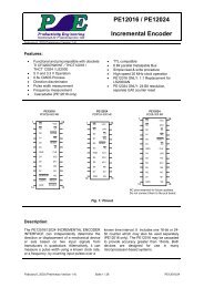
Watchdog State Diagram<br />
Initial status<br />
bad<br />
O/F<br />
good<br />
bad<br />
Explanation<br />
1/NF<br />
bad<br />
Preliminary Information<br />
good<br />
bad<br />
2/NF<br />
bad<br />
bad<br />
1/F 2/F<br />
good<br />
Figure 4. Watchdog state diagram<br />
good<br />
good<br />
3/NF<br />
good<br />
In each block, the first character represents the state of the<br />
counter. The second notation indicates the fault status of<br />
the counter. A fault status is indicated by an ”F” and a no<br />
fault status is indicated by an ”NF”. When the watchdog<br />
is powered up initially, the counter starts out at the 0/F<br />
block (initial state). ”Good” indicates that a pulse has<br />
been received whose width resides within the timing window.<br />
”Bad” indicates that a pulse has been received<br />
whose width is either too short or too long.<br />
Watchdog-Window Calculation<br />
Example with recommended values<br />
Cosc = 3.3 nF (should be preferably 10%, NPO)<br />
Rosc= 39 k� (may be 5%, Rosc fWDC = 10 kHz<br />
fWDI = 100 Hz –> tWDI = 10 ms<br />
TELEFUNKEN Semiconductors<br />
Rev. A1, 03-Dec-97