Semiconductor Characterization System Technical Data - Helmar
Semiconductor Characterization System Technical Data - Helmar
Semiconductor Characterization System Technical Data - Helmar

Create successful ePaper yourself
Turn your PDF publications into a flip-book with our unique Google optimized e-Paper software.
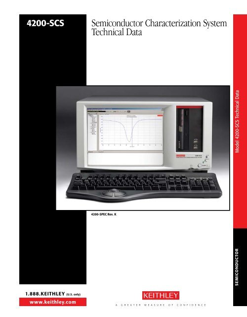
4200-ScS <strong>Semiconductor</strong> <strong>Characterization</strong> <strong>System</strong><br />
<strong>Technical</strong> <strong>Data</strong><br />
1.888.KEITHLEY (U.S. only)<br />
www.keithley.com<br />
4200-SPEc rev. K<br />
A G R E A T E R M E A S U R E O F C O N F I D E N C E<br />
Model 4200-SCS <strong>Technical</strong> <strong>Data</strong><br />
SEmIcondUcTor
Model 4200-SCS <strong>Technical</strong> <strong>Data</strong><br />
SEmIcondUcTor<br />
2<br />
4200-ScS <strong>Semiconductor</strong> <strong>Characterization</strong> <strong>System</strong><br />
<strong>Technical</strong> <strong>Data</strong><br />
2 Introduction<br />
3 configuration options<br />
5 Hardware Specifications<br />
14 KTE Interactive Software Tools<br />
14 Microsoft Windows<br />
15 The Keithley Interactive Test<br />
Environment (KITE)<br />
22 Keithley User Library Tool<br />
(KULT)<br />
23 <strong>System</strong> Configuration and<br />
Diagnostics (KCON)<br />
23 Keithley External Control<br />
Interface (KXCI)<br />
24 Support contracts<br />
25 Value-Add Services<br />
25 Upgrades<br />
26 Warranty Information<br />
26 Embedded Pc Policy<br />
26 Switch matrix Support and<br />
configurations<br />
28 optional Accessories<br />
1.888.KEITHLEY (U.S. only)<br />
www.keithley.com<br />
Introduction<br />
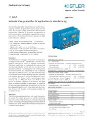
The Model 4200-SCS provides a total system solution for DC I-V, C-V,<br />
and pulse characterization and stress-measure/reliability testing of<br />
semiconductor devices and test structures. This advanced parameter<br />
analyzer provides intuitive and sophisticated capabilities for semiconductor<br />
device characterization. The 4200-SCS combines unprecedented<br />
measurement speed and accuracy with an embedded Windows ® -based<br />
PC and the Keithley Interactive Test Environment (KITE) to provide a<br />
powerful single-box solution.<br />
The Keithley Interactive Test Environment allows users to gain familiarity<br />
quickly with tasks such as managing tests and results and generating<br />
reports. Sophisticated and simple test sequencing and external instrument<br />
drivers simplify performing automated device and wafer testing with<br />
combined I-V and C-V measurements. Our new integrated capacitancevoltage<br />
measurement unit, the Model 4210-CVU, makes C-V measurements<br />
as easy as DC measurements.<br />
The 4200-SCS is modular and configurable. The system supports up to<br />
nine Source-Measure Units, including up to nine high power SMUs with<br />
1A/20W capability. An optional Remote PreAmp extends the resolution of<br />
any Source-Measure Unit from 100fA to 0.1fA.<br />
KTEI provides software support for DC SMUs and a number of new<br />
instruments. Besides the C-V measurement unit described previously,<br />
it supports a dual-channel pulse generator card (the Model 4205-PG2)<br />
that plugs into one of the Model 4200-SCS’s slots, just like an SMU, and a<br />
choice of dual-channel digital oscilloscopes for time- and voltage-domain<br />
measurements. Together, the pulse generator and oscilloscope make it<br />
simple and cost-effective to integrate pulsing, waveform generation, and<br />
signal observation capabilities into the Model 4200-SCS’s test environment.<br />
Our KTEI software supports three test application packages to expand<br />
the Model 4200-SCS’s pulsed testing capabilities: 4200-PIV-A performs<br />
charge trapping and isothermal testing for leading-edge CMOS research;<br />
4200-PIV-Q tests for higher power pulse in III-V, LDMOS, and other<br />
higher frequency FET devices; and 4200-FLASH tests FLASH embedded<br />
memory devices.<br />
A G R E A T E R M E A S U R E O F C O N F I D E N C E
4200-ScS <strong>Semiconductor</strong> <strong>Characterization</strong> <strong>System</strong><br />
<strong>Technical</strong> <strong>Data</strong><br />
configuration options<br />
The 4200-SCS supports many instrument configurations that can include SMUs, C-V measurement<br />
units, pulse generators, and oscilloscopes. The standard configuration includes two medium power<br />
Source-Measure Units (SMUs) and a Ground Unit.<br />
Standard 4200-ScS models<br />
4200-SCS/F Chassis<br />
12.1˝ flat panel display<br />
Two (2) Model 4200-SMU medium power SMUs<br />
One (1) Remote Sense Ground Unit<br />
LAN, GPIB, USB, RS-232, parallel port, hard disk, DVD/CD-RW<br />
4200-SCS/C Chassis<br />
Composite Front Bezel (i.e., no built-in display)<br />
Two (2) Model 4200-SMU medium power SMUs<br />
One (1) Remote Sense Ground Unit<br />
LAN, GPIB, USB, RS-232, parallel port, hard disk, DVD/CD-RW<br />
Source-measure Units<br />
Each system can be configured with up to seven additional SMUs, for a total of nine SMUs. Two SMU<br />
models are available: a medium power (100mA, 2W) version (Model 4200-SMU) and a high power<br />
(1A, 20W) version (Model 4210-SMU). The system can support up to nine high power SMUs.<br />
4200-ScS Source-measure Units<br />
mAxImUm mAxImUm mAxImUm<br />
VoLTAgE cUrrEnT PoWEr<br />
4200-SMU (medium power) 210V 100mA 2W<br />
4210-SMU (high power) 210V 1A 20W<br />
remote PreAmp<br />
The low current measurement capabilities of any SMU can be extended<br />
by adding an optional Remote PreAmp (Model 4200-PA). The 4200-PA<br />
provides 0.1fA resolution by effectively adding five current ranges to either<br />
SMU model. The PreAmp module is fully integrated with the system;<br />
to the user, the SMU simply appears to have additional meas urement<br />
resolution available. The Remote PreAmp is shipped installed on the<br />
back panel of the 4200-SCS for local operation. This installation allows<br />
for standard cabling to a prober, test fixture, or switch matrix. Users can<br />
remove the PreAmp from the back panel and place it in a remote location<br />
(such as in a light-tight enclosure or on the prober platen) to eliminate<br />
measurement problems due to long cables. Platen mounts and triax panel<br />
mount accessories are available. Remore PreAmps are installed at the<br />
factory in numerical order, i.e., SMU1, SMU2, SMU3 … up to the number<br />
of PreAmps specified.<br />
capacitance-Voltage Instrument<br />
C-V measurements are now as easy to perform as I-V measurements with<br />
the new integrated C-V instrument, the Model 4210-CVU. This optional<br />
capacitance-voltage instrument performs capacitance measurements from<br />
femtofarads (fF) to nanofarads (nF) at frequencies from 1kHz to 10MHz.<br />
It also supplies diagnostic tools that ensure the validity of your C-V<br />
test results.<br />
1.888.KEITHLEY (U.S. only)<br />
www.keithley.com<br />
With this system, you can configure linear or custom C-V, C-f, and C-t<br />
sweeps with up to 4096 data points. In addition, through the open<br />
environment of the 4200-SCS, you can modify any of the included tests.<br />
Pulse generator<br />
The Model 4205-PG2 Dual-Channel Pulse Generator provides dual-channel<br />
pulsing with voltage pulses as short as 10ns in high speed mode or up to<br />
±20V (into 50W) in high voltage mode. It supports two new waveform<br />
generation modes in addition to the standard pulse capability. The<br />
Arbitrary Waveform Mode can generate complex waveforms made up of<br />
up to 256K data points at clock speeds up to 25MHz. The Segment ARB<br />
Mode (patent-pending) generates waveforms made up of up to 1024 userdefined<br />
line segments. Each segment can have a different duration.<br />
oscilloscope<br />
The system supports two dual-channel integrated digital oscilloscope<br />
options: the Model 4200-SCP2 offers 8-bit resolution with a sample rate<br />
up to 2.5 gigasamples/second, while the Model 4200-SCP2HR provides<br />
16-bit resolution and a sample rate up to 400 megasamples/second. Both<br />
can be programmed for automated measurement and data acquisition<br />
or used with the stand-alone GUI application provided to perform<br />
traditional oscilloscope tasks. They provide measurements in both the time<br />
(frequency, rise/fall time) and voltage domains (amplitude, peak-peak, etc.).<br />
A G R E A T E R M E A S U R E O F C O N F I D E N C E<br />
Model 4200-SCS <strong>Technical</strong> <strong>Technical</strong> <strong>Data</strong><br />
SEmIcondUcTor<br />
3
Model 4200-SCS <strong>Technical</strong> <strong>Data</strong><br />
SEmIcondUcTor<br />
4<br />
4200-ScS <strong>Semiconductor</strong> <strong>Characterization</strong> <strong>System</strong><br />
<strong>Technical</strong> <strong>Data</strong><br />
1.888.KEITHLEY (U.S. only)<br />
www.keithley.com<br />
configuration Examples<br />
The 4200-SCS’s plug-in chassis design offers exceptional configuration flexibility, as the following<br />
examples illustrate. A chassis can contain up to nine SMUs in any combination of high and medium<br />
powered units. Any configuration can be specified without a flat panel display by substituting the<br />
4200-SCS/C for the 4200-SCS/F. However, an external SVGA monitor is required to operate the<br />
4200-SCS/C. Basic <strong>Characterization</strong> <strong>System</strong> Configuration<br />
Basic characterization <strong>System</strong> configuration<br />
Configuration: One (1) Model 4200-SCS/F<br />
Three (3) Model 4200-SMU medium power SMUs<br />
One (1) Model 4200-PA Remote PreAmp module<br />
One (1) Remote Sense Ground Unit<br />
Description: A general-purpose configuration for characterizing transistors and other devices.<br />
maximum dc configuration<br />
Configuration: One (1) Model 4200-SCS/F (includes two medium power SMUs as the standard<br />
configuration, which can be substituted with two high power SMUs)<br />
Seven (7) additional Model 4210-SMUs (total of nine; all nine can<br />
be high power SMUs)<br />
Nine (9) Model 4200-PA Remote PreAmp modules<br />
Description: Provides a nine-SMU system with 0.1fA sensitivity on all nine SMUs<br />
and 1A capability on all nine channels.<br />
maximum Pulse configuration<br />
Configuration: One (1) Model 4200-SCS/F<br />
Four (4) Model 4205-PG2 dual-channel pulse generators (8 channels)<br />
One (1) digital oscilloscope (Model 4200-SCP2 or 4200-SCP2HR)<br />
Four (4) Model 4200-SMUs<br />
Four (4) Model 4200-PA Remote PreAmp modules<br />
Description: Provides a four-SMU system with eight channels that support traditional pulse<br />
mode, arbitrary waveform mode (ARB), Segment ARB waveform mode<br />
(Segment ARB or SARB), and trigger-in. Each pulse channel contains an inline<br />
High Endurance Output Relay (solid-state relay). The oscilloscope provides pulse<br />
measure and waveform monitoring.<br />
Example Broad Use case configuration<br />
Configuration: One (1) Model 4200-SCS/F<br />
Three (3) Model 4205-PG2 dual-channel pulse generators (8 channels)<br />
One (1) digital oscilloscope (Model 4200-SCP2 or 4200-SCP2HR)<br />
Four (4) Model 4200-SMUs<br />
Four (4) Model 4200-PA Remote PreAmp modules<br />
One (1) Model 4210-CVU Capacitance-Voltage Instrument<br />
Description: Provides an ultra-flexible multi-use system for a broad range of parametric tests,<br />
including very low-level DC measurements, C-V, and pulse sourcing.<br />
A G R E A T E R M E A S U R E O F C O N F I D E N C E
4200-ScS <strong>Semiconductor</strong> <strong>Characterization</strong> <strong>System</strong><br />
<strong>Technical</strong> <strong>Data</strong><br />
Hardware Specifications<br />
dc SmU Hardware Specifications<br />
cUrrEnT SPEcIfIcATIonS<br />
4210-<br />
SmU 2<br />
High<br />
Power<br />
SmU<br />
4200-<br />
SmU 2<br />
medium<br />
Power<br />
SmU<br />
4200-SmU and<br />
4210-SmU with<br />
optional<br />
4200-PA PreAmp<br />
cUrrEnT<br />
rAngE1 mEASUrE SoUrcE<br />
mAx.<br />
VoLTAgE rESoLUTIon3 AccUrAcY<br />
±(% rdg + amps) rESoLUTIon3 AccUrAcY<br />
±(% rdg + amps)<br />
1 A 21 V 1 µA 0.100% + 200 µA 50 µA 0.100% + 350 µA<br />
100 mA 210 V 100 nA 0.045% + 3 µA 5 µA 0.050% + 15 µA<br />
100 mA 21 V 100 nA 0.045% + 3 µA 5 µA 0.050% + 15 µA<br />
10 mA 210 V 10 nA 0.037% + 300 nA 500 nA 0.042% + 1.5 µA<br />
1 mA 210 V 1 nA 0.035% + 30 nA 50 nA 0.040% + 150 nA<br />
100 µA 210 V 100 pA 0.033% + 3 nA 5 nA 0.038% + 15 nA<br />
10 µA 210 V 10 pA 0.050% + 600 pA 500 pA 0.060% + 1.5 nA<br />
1 µA 210 V 1 pA 0.050% + 100 pA 50 pA 0.060% + 200 pA<br />
100 nA 210 V 100 fA 0.050% + 30 pA 5 pA 0.060% + 30 pA<br />
10 nA 210 V 10 fA 0.050% + 1 pA 500 fA 0.060% + 3 pA<br />
1 nA 210 V 3 fA 0.050% + 100 fA 50 fA 0.060% + 300 fA<br />
100 pA 210 V 1 fA 0.100% + 30 fA 15 fA 0.100% + 80 fA<br />
10 pA 210 V 0.3 fA 0.500% + 15 fA 5 fA 0.500% + 50 fA<br />
1 pA 210 V 100 aA 1.000% + 10 fA 1.5 fA 1.000% + 40 fA<br />
voltage ComplianCe: Bipolar limits set with a single value between full scale and 10% of selected voltage range.<br />
VoLTAgE SPEcIfIcATIonS<br />
VoLTAgE<br />
rAngE1 mAx.<br />
cUrrEnT mEASUrE SoUrcE<br />
4200-SmU 4210-SmU resolution3 Accuracy<br />
±(% rdg + volts) resolution3 Accuracy<br />
±(% rdg + volts)<br />
200 V 4 10.5 mA 105 mA 200 µV 0.015% + 3 mV 5 mV 0.02% + 15 mV<br />
20 V 105 mA 1.05 A 20 µV 0.01 % + 1 mV 500 µV 0.02% + 1.5 mV<br />
2 V 105 mA 1.05 A 2 µV 0.012% + 150 µV 50 µV 0.02% + 300 µV<br />
200 mV 105 mA 1.05 A 1 µV 0.012% + 100 µV 5 µV 0.02% + 150 µV<br />
Current ComplianCe: Bipolar limits set with a single value between full scale and 10% of selected current range.<br />
Supplemental Information<br />
Supplemental information is not warranted but provides useful infor mation<br />
about the Models 4200-SMU, 4210-SMU, and 4200-PA.<br />
ComplianCe aCCuraCy:<br />
Voltage compliance equals the voltage source specifications.<br />
Current compliance equals the current source specifications.<br />
overshoot:
Model 4200-SCS <strong>Technical</strong> <strong>Data</strong><br />
SEmIcondUcTor<br />
6<br />
4200-ScS <strong>Semiconductor</strong> <strong>Characterization</strong> <strong>System</strong><br />
<strong>Technical</strong> <strong>Data</strong><br />
1.888.KEITHLEY (U.S. only)<br />
www.keithley.com<br />
Additional dc SmU Specifications<br />
max. output power: 22 watts for 4210-SMU and 2.2 watts for 4200-SMU<br />
(both are four-quadrant source/sink operation).<br />
DC floating voltage: COMMON can be floated ±32 volts from chassis<br />
ground.<br />
VoLTAgE monITor (SmU in VmU mode):<br />
measure<br />
Voltage measure Accuracy<br />
range resolution ±(%rdg + volts)<br />
200 V 200 µV 0.015% + 3 mV<br />
20 V 20 µV 0.01% + 1 mV<br />
2 V 2 µV 0.012% + 110 µV<br />
200 mV 1 µV 0.012% + 80 µV<br />
input impeDanCe: >10 13 W.<br />
input leakage Current:
4200-ScS <strong>Semiconductor</strong> <strong>Characterization</strong> <strong>System</strong><br />
<strong>Technical</strong> <strong>Data</strong><br />
model 4210-cVU Specifications<br />
mEASUrEmEnT fUncTIonS<br />
measurement parameters: Cp-G, Cp-D, Cs-Rs, Cs-D, R-jX,<br />
Z-theta.<br />
ranging: Auto and fixed.<br />
measurement terminal Configuration:<br />
Four-terminal pair.<br />
ConneCtor type: Four SMA (female) connectors.<br />
Cable length: 0m, 1.5m, 3m, or custom selectable.<br />
integration time: FAST, NORMAL, QUIET, and CUSTOM.<br />
TEST SIgnAL<br />
frequenCy range: 1kHz to 10MHz.<br />
minimum resolution: 1kHz, 10kHz, 100kHz, 1MHz<br />
depending on frequency range.<br />
sourCe frequenCy aCCuraCy: ±0.1%.<br />
signal output level range: 10mV rms to 100mV rms.<br />
resolution: 1mV rms.<br />
aCCuraCy: ±(10.0% + 1mV rms) unloaded (at rear panel).<br />
output impeDanCe: 100W, typical.<br />
dc BIAS fUncTIon<br />
DC voltage bias:<br />
range: ±30V (±60V differential).<br />
resolution: 1.0mV.<br />
Accuracy: ±(0.5% + 5.0mV) unloaded.<br />
maximum DC Current: 10mA.<br />
SWEEP cHArAcTErISTIcS<br />
available sweep parameters: DC bias voltage, frequency,<br />
AC voltage.<br />
sweep type: Linear, custom.<br />
sweep DireCtion: Up sweep, down sweep.<br />
number of measurement points: 4096.<br />
ExAmPLE of IncLUdEd LIBrArIES<br />
• C-V, C-t, and C-f measurements and analysis of:<br />
– High and low k structures<br />
– MOSFETs<br />
– BJTs<br />
– Diodes<br />
– III-V compound devices<br />
– Carbon nanotube (CNT) devices<br />
• Doping profiles, T OX, and carrier lifetime tests<br />
• Junction, pin-to-pin, and interconnect capacitance measurements<br />
• Solar cells including Si, organic, thin film, CIGS, etc.<br />
The C-V instrument integrates directly into the Model 4200-SCS<br />
chassis. It can be purchased as an upgrade to existing systems or<br />
as an option for new systems.<br />
1.888.KEITHLEY (U.S. only)<br />
www.keithley.com<br />
mEASUrEmEnT AccUrAcY<br />
Example of C/G Measurement Accuracy<br />
measured c<br />
frequency capacitance Accuracy 1<br />
g<br />
Accuracy<br />
10 MHz 3<br />
1 pF ± 0.92% ± 260 ns<br />
10 pF<br />
100 pF<br />
± 0.32%<br />
± 0.29%<br />
± 990 ns<br />
± 9 µs<br />
1 nF ± 0.35% ± 99 µs<br />
1 pF ± 0.38% ± 15 ns<br />
1 MHz<br />
10 pF<br />
100 pF<br />
± 0.16%<br />
± 0.09%<br />
± 65 ns<br />
± 590 ns<br />
1 nF ± 0.09% ± 4 µs<br />
10 pF ± 0.17% ± 15 ns<br />
100 kHz<br />
100 pF<br />
1 nF<br />
± 0.18%<br />
± 0.08%<br />
± 59 ns<br />
± 450 ns<br />
10 nF ± 0.08% ± 3 µs<br />
100 pF ± 0.26% ± 15 ns<br />
10 kHz<br />
1 nF<br />
10 nF<br />
± 0.15%<br />
± 0.08%<br />
± 66 ns<br />
± 450 ns<br />
100 nF ± 0.08% ± 3 µs<br />
1 nF ± 0.69% ± 40 ns<br />
1 kHz<br />
10 nF<br />
100 nF<br />
± 0.25%<br />
± 0.10%<br />
± 120 ns<br />
± 500 ns<br />
1 µF ± 0.15% ± 10 µs<br />
noTES<br />
1. The capacitance and conductance measurement accuracy is specified<br />
under the following conditions: D X < 0.1.<br />
2. Conductance accuracy is specified as the maximum conductance<br />
measured on the referenced capacitor.<br />
3. These specs are typical. Typical and supplemental specs are<br />
non- warranted, apply at 23°C, and are provided solely as useful<br />
information.<br />
Integration time: QUIET.<br />
Test signal level: 30mV rms.<br />
At the rear panel of the 4210-CVU.<br />
1, 2<br />
SUPPLEmEnTAL cABLE SPEcIfIcATIon<br />
4210-cVU Typical c Accuracy with 1.5m cables<br />
(supplemental)<br />
measured<br />
capac itance 1 kHz 10 kHz 100 kHz 1 mHz 10 mHz<br />
1 pF N/A ±8.38% ±1.95% ±0.43% N/A<br />
10 pF N/A ±0.94% ±0.21% ±0.18% ±1%<br />
100 pF N/A ±0.29% ±0.20% ±0.15% ±1%<br />
1 nF ±0.72% ±0.17% ±0.12% ±0.16% ±2%<br />
10 nF ±0.28% ±0.12% ±0.13% ±0.25% ±2%<br />
100 nF ±0.12% ±0.13% ±0.22% ±1.14% N/A<br />
1 µF ±0.17% ±0.21% N/A N/A N/A<br />
4210-cVU Typical c Accuracy with 3m cables<br />
(supplemental)<br />
measured<br />
capac itance 1 kHz 10 kHz 100 kHz 1 mHz 10 mHz<br />
1 pF N/A ±8.5 % ±2.05% ±0.57% N/A<br />
10 pF N/A ±0.96% ±0.23% ±0.21% ±1%<br />
100 pF N/A ±0.29% ±0.20% ±0.17% ±1%<br />
1 nF ±0.72% ±0.17% ±0.12% ±0.18% ±2%<br />
10 nF ±0.28% ±0.12% ±0.13% ±0.27% ±2%<br />
100 nF ±0.12% ±0.13% ±0.22% ±1.16% N/A<br />
1 µF ±0.17% ±0.21% N/A N/A N/A<br />
cVU confIdEncE cHEcK<br />
The 4210-CVU includes a diagnostic tool called Confidence<br />
Check. It allows users to check the integrity of open and short<br />
connections and connections to a device-under test (DUT).<br />
When the Model 4210-CVU is connected to a DUT, Confidence<br />
Check displays the measured readings in real time. This also<br />
allows Confidence Check to be used as a C-V meter to perform<br />
quick and accurate measurements.<br />
c-V PoWEr PAcKAgE TYPIcAL<br />
PErformAncE cHArAcTErISTIcS<br />
measurement parameters: Cp-Gp, DCV, timestamp.<br />
ranging: 1pF to 1nF.<br />
measurement terminals: 2-wire SMA, with BNC adapters.<br />
test signal: 100kHz to 10MHz, 10mV to 100mV.<br />
DC voltage sourCe: ±200V with 5mV resolution.<br />
DC Current: 100mA or 300mA maximum.<br />
typiCal Cp aCCuraCy @ 1mhz: 1.0%.<br />
DC Current sensitivity: 10nA/V.<br />
smu bias terminals supporteD: 4.<br />
A G R E A T E R M E A S U R E O F C O N F I D E N C E<br />
Model 4200-SCS <strong>Technical</strong> <strong>Technical</strong> <strong>Data</strong><br />
SEmIcondUcTor<br />
7
Model 4200-SCS <strong>Technical</strong> <strong>Data</strong><br />
SEmIcondUcTor<br />
8<br />
4200-ScS <strong>Semiconductor</strong> <strong>Characterization</strong> <strong>System</strong><br />
<strong>Technical</strong> <strong>Data</strong><br />
4205-Pg2 dual-channel Pulse generator Specifications 1, 2<br />
The 4205-PG2 includes three operational modes for flexible, reconfigurable pulsing:<br />
• Standard pulse<br />
– Pulse between any two voltage levels<br />
– Period range: 20ns to 1s<br />
• Arbitrary (ARB) waveform<br />
– Output ARB waveforms built from standard wave libraries or sampled data<br />
– Depth: 256K points/channel<br />
– Timebase: 20ns/point up to 1sec/point, fixed timebase for entire waveform<br />
– Waveform Libraries: sine, ramp, gaussian, white noise<br />
– Input in .csv format<br />
• Segment ARB waveform<br />
– With a single pulse channel, build multi-level and multi-pulse waveforms with user-defined<br />
line segments<br />
– Depth: 1024 segments/channel<br />
– Parameters for each segment: Segment #, start voltage, stop voltage, segment time,<br />
trigger out, High Endurance Output relay (HEOR/SSR) on/off<br />
– Time per segment: 20ns to 1s, 10ns increments (each segment can have a different duration)<br />
PULSE/LEVEL 3<br />
High Speed High Voltage<br />
vout 50 W into 50 W –5V to +5V –20V to +20V<br />
vout 50 W into 1 MW –10V to +10V –40V to +40V<br />
accuracy ±(3% + 50 mV) ±(3% + 100 mV)<br />
amplitude/level 50 W into 50 W 1 mV 5 mV<br />
resolution 50 W into 1 MW 2 mV 10 mV<br />
output Connectors SMA SMA<br />
source impedance 50W Nominal 50W Nominal<br />
1% 1%<br />
short Circuit Current ±200 mA ±800 mA<br />
Current into 50W load<br />
(at full scale)<br />
±100 mA typical ±400 mA typical<br />
baseline noise ±(0.1% + 5 mV) RMS typical ±(0.1% + 5 mV) RMS typical<br />
overshoot/pre-shoot/ringing ±5% of amplitude ±20mV ±5% of amplitude ±80mV<br />
output limit Programmable limit to protect the DUT<br />
1.888.KEITHLEY (U.S. only)<br />
www.keithley.com<br />
TImIng<br />
High Speed High Voltage<br />
frequency range 1 Hz to 50 MHz 1 Hz to 2 MHz<br />
timing resolution 10 ns 10 ns<br />
rms Jitter (period, width) 0.01 % + 200 ps typical 0.01 % + 200 ps typical<br />
period range 20 ns to 1 s 500 ns to 1 s<br />
accuracy ±1% ±1%<br />
pulse width range 10ns to (period – 10ns) 250ns to (period – 100ns)<br />
accuracy ±(3% + 200 ps) ±(3% + 5ns)<br />
programmable<br />
transition time (0–100%)<br />
10 ns–33 ms 100 ns–33 ms<br />
transition slew rate4 accuracy<br />
linearity<br />
±1% for transition time<br />
4200-ScS <strong>Semiconductor</strong> <strong>Characterization</strong> <strong>System</strong><br />
<strong>Technical</strong> <strong>Data</strong><br />
4200-ScP2 1.25gS dual-channel oscilloscope card and<br />
4200-ScP2Hr 200mS dual-channel oscilloscope card Specifications 1<br />
AnALog InPUT 1<br />
4200-ScP2 4200-ScP2Hr<br />
no. of Channels 2 2<br />
bandwidth (50W) DC to 750 MHz DC to 250 MHz, typical<br />
bandwidth (1mW) DC to 350 MHz DC to 125 MHz, typical<br />
full scale input range (50 W)<br />
0.05, 0.1, 0.25, 0.5, 1, 2, 5,<br />
10 (Vp-p)<br />
0.05, 0.1, 0.25, 0.5, 1, 2, 5,<br />
10 (Vp-p)<br />
full scale input range (1 mW)<br />
0.1, 0.2, 0.5, 1, 2.5, 5, 10, 20,<br />
50, 100 (Vp-p)<br />
0.25, 0.5, 1.25, 2.5, 5, 10, 25,<br />
50 (Vp-p)<br />
DC gain accuracy
Model 4200-SCS <strong>Technical</strong> <strong>Data</strong><br />
SEmIcondUcTor<br />
10<br />
4200-ScS <strong>Semiconductor</strong> <strong>Characterization</strong> <strong>System</strong><br />
<strong>Technical</strong> <strong>Data</strong><br />
4200-PIV-A Pulse I-V option<br />
The 4200-PIV-A package combines the 4205-PG2 dual-channel pulse<br />
generator with the 4200-SCP2 oscilloscope, a specialized interconnect, and<br />
patented software to provide a turnkey pulse I-V solution. The software<br />
controls sourcing from the pulse generator and data acquisition from the<br />
digital oscilloscope to automate a variety of pulse I-V tests. The specialized<br />
inter connect solves most of the problems typically encountered in high<br />
speed pulse testing:<br />
• Combining pulse and DC sources to a single DUT pin permits both DC<br />
and pulse characterization without the need for re-cabling or switching<br />
• Impedance matching, which minimizes reflection and maintains<br />
pulse fidelity<br />
• Easy setup as a result of straightforward cabling and connection<br />
to the DUT<br />
Pulse I-V for leading-edge CMOS devices:<br />
• Pulse voltage on gate, DC bias on drain<br />
• Measure drain current during gate pulse<br />
• ±5V pulses for the gate (40ns to 150ns), ±200V DC for the drain<br />
Included tests:<br />
• VDS –ID : Both pulse and DC.<br />
• VGS –ID : Both pulse and DC.<br />
• Single-pulse scope view: Useful for setup validation, pulse width<br />
optimization, and prototyping of novel pulse tests.<br />
1.888.KEITHLEY (U.S. only)<br />
www.keithley.com<br />
4200 PIV-A for cmoS Typical Specifications 1<br />
Channels: 2.<br />
typiCal pulse performanCe (with 4205 remote bias tee 4 ):<br />
measurement accuracy:
4200-ScS <strong>Semiconductor</strong> <strong>Characterization</strong> <strong>System</strong><br />
<strong>Technical</strong> <strong>Data</strong><br />
4200-PIV-Q Pulse I-V with Q point and<br />
dual channel Pulsing<br />
The 4200-PIV-Q package is designed for quiescent point pulsing for<br />
scaled-down RF transistors, such as HEMT and FET devices in III-V or<br />
LDMOS technologies. This package supports multiple 4205-PG2s and the<br />
4200-SCP2HR oscilloscope and includes capabilities such as dual-channel<br />
pulsing (i.e., for pulsing on both the gate and the drain simultaneously),<br />
higher power pulsing than the 4200-PIV-A package, and pulsing from a<br />
non-zero quiescent point. Pulse widths can be adjusted from 500ns to<br />
near-DC, and the same setup can also be used for performing true DC<br />
tests without re-cabling the system. The PIV-Q package is useful for a<br />
variety of large signal tests on high frequency transistors, as well as for<br />
investigation of dispersion phenomena and device performance at speed. It<br />
also offers a good approach for avoiding the isothermal problems inherent<br />
in DC testing.<br />
Dual-channel pulse I-V testing for III-V and LDMOS:<br />
• Pulse voltage on gate and drain.<br />
• Measure: gate current and drain voltage and current.<br />
• ±20V pulses for the gate, ±38V pulses for the drain. 6<br />
• Pulse Widths: 500ns to 999ms.<br />
Included tests:<br />
• VDS –ID : Both pulse and DC.<br />
• VGS –ID : Both pulse and DC.<br />
• Single-pulse scope view: Useful for setup validation, pulse width<br />
optimization, prototyping of novel pulse tests.<br />
1.888.KEITHLEY (U.S. only)<br />
www.keithley.com<br />
4200-PIV-Q Typical Specifications 1<br />
Channels: 2.<br />
typiCal pulse performanCe: 4<br />
measurement accuracy: Gate Current:
Model 4200-SCS <strong>Technical</strong> <strong>Data</strong><br />
SEmIcondUcTor<br />
12<br />
4200-ScS <strong>Semiconductor</strong> <strong>Characterization</strong> <strong>System</strong><br />
<strong>Technical</strong> <strong>Data</strong><br />
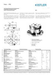
4200-PIV-Q Typical Specifications (continued)<br />
mAxImUm drAIn SoUrcE (40V range), typical<br />
maximum V d * (V) maximum I d * (A) r dS (W)<br />
6.65 1.33 5<br />
12.3 1.23 10<br />
25 1.0 25<br />
38 0.76 50<br />
50 0.54 92<br />
51.6 0.51 100<br />
65 0.26 250<br />
75.8 0.075 1k<br />
*Approximate maximum, does not account for interconnect losses.<br />
mAxImUm gATE SoUrcE (20V range ), typical<br />
maximum V g * (V) maximum I g * (A) r gS (W)<br />
3.6 0.769 5<br />
6.67 0.667 10<br />
13.3 0.533 25<br />
20 0.400 50<br />
*Approximate maximum, does not account for interconnect losses.<br />
Max. Drain Voltage (V)<br />
90<br />
80<br />
I V<br />
1.6<br />
1.4<br />
70<br />
1.2<br />
60<br />
1.0<br />
50<br />
40<br />
0.8<br />
30<br />
0.6<br />
20<br />
0.4<br />
10<br />
V<br />
I<br />
0.2<br />
0<br />
0.0<br />
1 10 100 1000 10000<br />
DUT Drain-Source Resistance (Ω)<br />
maximum Pulse drain I and V vs. drain-Source resistance<br />
1.888.KEITHLEY (U.S. only)<br />
www.keithley.com<br />
Max. Drain Current (A)<br />
STABILIzATIon KIT<br />
The stabilization kit for the 4200-PIV-Q, the 4200-Q-STBL-KIT, minimizes the oscillations caused<br />
be III-V RF transistors and LDMOS RF devices. The stabilization kit includes 10 resistors and 2<br />
blanks for customization.<br />
Stabilization resistor<br />
10 resistors (+ 2 blanks) in the kit<br />
A G R E A T E R M E A S U R E O F C O N F I D E N C E
4200-ScS <strong>Semiconductor</strong> <strong>Characterization</strong> <strong>System</strong><br />
<strong>Technical</strong> <strong>Data</strong><br />
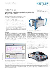
4200-fLASH non-volatile memory Test option<br />
The 4200-FLASH package tests single FLASH memory cells or small<br />
arrays. This package includes all the necessary code and the interconnect<br />
needed to perform a standard set of Flash memory tests for NAND or NOR<br />
technologies, with higher pulse voltages important for MLC technologies.<br />
The tests included generate program and/or erase cycles using the patentpending<br />
Segment ARB pulse mode as well as controlling the in-line High<br />
Endurance Output Relay. Endurance and Disturb tests are also included.<br />
Four channels of multi-level pulse:<br />
• ±40V pulsing into high impedance pin (±20V into 50W).<br />
• High Endurance Output Relay provides fast open/close for pin isolation<br />
during erase pulse.<br />
• Pulse Widths: 200ns to 1s.<br />
• Up to 25 pulse levels (100 pulse segments).<br />
Included tests:<br />
• Endurance.<br />
• Program-read.<br />
• Erase-read.<br />
• Disturb.<br />
Easy setup for program/erase cycles<br />
Typical nor fLASH gate program/erase cycle<br />
1.888.KEITHLEY (U.S. only)<br />
www.keithley.com<br />
4200-fLASH Typical Specifications 1<br />
Channels: 4 channels (optional 8 channels max.).<br />
typiCal pulse performanCe:<br />
number of voltage levels/waveform: 25.<br />
minimum transition time: 150ns.<br />
pulse source voltage range: 0 to ±20V into 50W. 0 to ±40V into high impedance.<br />
pulse width: 250ns to 1s.<br />
trigger synchronization/Jitter: ±8ns.<br />
switching time for Dut pin isolation: 100µs.<br />
heor off Capacitance: 250pF.<br />
smu typiCal DC performanCe<br />
typical DC leakage:
Model 4200-SCS <strong>Technical</strong> <strong>Data</strong><br />
SEmIcondUcTor<br />
14<br />
4200-ScS <strong>Semiconductor</strong> <strong>Characterization</strong> <strong>System</strong><br />
<strong>Technical</strong> <strong>Data</strong><br />
1.888.KEITHLEY (U.S. only)<br />
www.keithley.com<br />
KTE Interactive Software Tools<br />
KTE Interactive includes a variety of software tools for operating and maintaining the 4200-SCS:<br />
• Keithley Interactive Test Environment (KITE)—The 4200-SCS device characterization application<br />
• Keithley User Library Tool (KULT)—Allows test engineers to integrate custom algorithms into<br />
KITE using 4200-SCS or external instruments.<br />
• Keithley Configuration Utility (KCON)—Allows test engineers to define the configuration of GPIB<br />
instruments, switch matrices, and analytical probers connected to the 4200-SCS. It also provides<br />
system diagnostics functions.<br />
• Keithley External Control Interface (KXCI)—The 4200-SCS application for controlling the<br />
4200-SCS from an external computer via the GPIB bus or Ethernet.<br />
• KPulse—A graphical user interface (GUI) that is a non-programming alternative to configure and<br />
control the installed Model 4205-PG2 pulse generator cards. It is used for quick tests requiring<br />
minimal interaction with other Model 4200-SCS test resources.<br />
(Note: KPulse is only included with the 4205-PG2, 4200-PIV-A, 4200-PIV-Q, and 4200-FLASH.)<br />
• KScope—A graphical user interface (GUI) that provides a non-programming alternative to control<br />
the system’s scope card (either Model 4200-SCP2HR or Model 4200-SCP2).<br />
(Note: KScope is only included with the 4200-SCP2, 4200-SCP2HR, 4200-PIV-A, and 4200-PIV-Q.)<br />
microsoft Windows<br />
Windows Operating <strong>System</strong><br />
The operating system is a standard distribution of Microsoft Windows. Upgrades are available<br />
for older systems. Contact the Keithley factory for supported versions and service packs.<br />
<strong>Data</strong> Security and Recovery<br />
<strong>Data</strong> security and recovery are handled by the included software package, Acronis True Image. This<br />
utility can be used to create exact hard disk images, including all operating systems, applications and<br />
configuration files, software updates, personal settings, and data. If failures occur that block access to<br />
information or affect system operation, or if files are accidentally deleted, the user can easily restore<br />
the system and lost data with the Acronis tool.<br />
data Storage<br />
Fixed disk<br />
Internal high capacity fixed disk drive stores the operating system, application programs,<br />
and data files.<br />
DVD/CD-RW Drive<br />
Standard DVD/CD read-write drive is provided for data storage and retrieval.<br />
USB Ports<br />
Four USB 2.0 ports for typical PC USB peripherals.<br />
connectivity<br />
The 4200-SCS includes two LAN Ethernet ports (10/100/1000) with software drivers installed.<br />
A G R E A T E R M E A S U R E O F C O N F I D E N C E
4200-ScS <strong>Semiconductor</strong> <strong>Characterization</strong> <strong>System</strong><br />
<strong>Technical</strong> <strong>Data</strong><br />
1.888.KEITHLEY (U.S. only)<br />
www.keithley.com<br />
The Keithley Interactive Test Environment (KITE)<br />
The Keithley Interactive Test Environment (KITE) is the Model 4200-SCS Windows device<br />
characterization application. It provides advanced test definition, parameter analysis and graphing,<br />
and automation capabilities required for modern semiconductor characterization.<br />
KITE Projects<br />
A project is a collection of related tests, organized in a hierarchy that parallels the physical layout<br />
of the devices on a wafer. KITE operates on projects using an interface called the project navigator.<br />
The project navigator simplifies organizing test files, test execution, and test sequencing.<br />
The project navigator organizes tests into a logical hierarchy presented in a browser style format.<br />
This structure allows users to define projects around wafer testing:<br />
The project level organizes subsites and controls wafer looping execution.<br />
The subsite level organizes devices and controls subsite test sequencing.<br />
The device level organizes test modules, manages test module libraries, and controls device<br />
test sequencing.<br />
The test module level performs tests, analyzes data, and plots results.<br />
Selectable checkboxes allow enabling/disabling individual tests/plans.<br />
Test modules<br />
Within KITE, two types of test modules are provided to capture the test input parameters, data<br />
analysis, and plot setting for data. “Interactive Test Modules” provide a point-and-click interface for<br />
defining test input parameters and controlling the 4200-SCS SMUs. “User Test Modules” provide a<br />
fill-in-the-blank interface to either factory-provided or user-written C language subroutines. These<br />
subroutines can control internal 4200-SCS instruments and/or external instruments and systems<br />
through the RS-232 or GPIB interface. This dual approach provides an extendable test environment<br />
that gives the users the same capabilities for data analysis, plotting, and output and automation,<br />
whether the instrument used is part of the base system or an external instrument. It also offers users<br />
the flexibility to write complex test algorithms for control of either internal or external instruments.<br />
definition Tab—Interactive Test module<br />
The Definition Tab of an ITM provides a point-and-click interface for setting test input parameters<br />
that control the 4200-SCS SMUs and defining parameter extractions. Two modes are available:<br />
sweep mode<br />
Forcing Common, Voltage Bias, Current Bias (VMU), Voltage Sweep, Current<br />
Functions: Sweep, Voltage Step, Current Step, Voltage List Sweep, Current List<br />
Sweep, Open1, 2 , C-V Differential Bias<br />
Measuring Measure Current or Programmed Current, Measure Voltage or<br />
Functions: Programmed Voltage.<br />
C-V Measurement parameters: Cp-G, Cp-D, Cs-Rs, Cs-D, R-jX, Z-theta.<br />
Fast, Normal, Quiet, and Custom Integration Times<br />
Measure voltage, current or both on each sweep point, regardless of<br />
forcing function.<br />
1. Pulse SMU: The system’s SMUs can now be set to provide pulse output for sweep (linear, log, and list) and bias forcing functions.<br />
This involves having the SMU pulse, which is different than the PG2 pulse mode. Pulse “on” and “off” times can be set from 5ms<br />
to 10s. Pulse output goes to the specified pulse level during the pulse “on” time and back to a user-defined base voltage during the<br />
“off” time. If the SMU is also set to measure, the measurement will occur after the “on” time expires and before the transition to<br />
the “off” time level. If it’s not set to measure, the output will simply transition from “on” to “off.”<br />
2. Standby: There’s a new checkbox in the Timing window called “Disable outputs at completion,” which is checked by default. If this<br />
box is unchecked, the SMU outputs will stay at their last values when the test is complete (instead of returning to zero or “idle”<br />
state). These values then change when a new test is started (if that particular SMU is required in the new test), or KITE is exited,<br />
or a UTM calls a “DEVINT.”<br />
A G R E A T E R M E A S U R E O F C O N F I D E N C E<br />
Model 4200-SCS <strong>Technical</strong> <strong>Technical</strong> <strong>Data</strong><br />
SEmIcondUcTor<br />
15
Model 4200-SCS <strong>Technical</strong> <strong>Data</strong><br />
SEmIcondUcTor<br />
16<br />
4200-ScS <strong>Semiconductor</strong> <strong>Characterization</strong> <strong>System</strong><br />
<strong>Technical</strong> <strong>Data</strong><br />
Interactive Test modules (ITm) are built from<br />
three different major functions: definition,<br />
Sheet, and graph. The definition Tab allows<br />
the operator to define a sweep or sampling<br />
mode test using a graphical approach. The<br />
Sheet Tab stores acquired data and provides<br />
an Excel ® -like workbook for viewing and<br />
analyzing test results. The graph Tab provides<br />
a full-featured data plotting tool capable of<br />
producing report-ready graphs. The Status<br />
Tab reports any errors that would interfere<br />
with test execution.<br />
The User Test module (UTm) has virtually identical functionality as the<br />
ITm. However, users enter input parameters in a tabular interface in<br />
the UTm’s definition Tab.<br />
1.888.KEITHLEY (U.S. only)<br />
www.keithley.com<br />
sampling mode<br />
Linear sampling of up to 4096 points. Sampling period is programmable from 1ms to 1000s.<br />
Additional hold delay before first sample of up to 1000s.<br />
definition Tab—User Test module<br />
The Definition Tab of a UTM presents users a tabular fill-in-the-blank interface for entering input<br />
parameters to call a C language subroutine. UTMs provide the ability to control internal SMUs and<br />
GPIB and RS-232 devices. This screen allows the user to select a user library, a subroutine module,<br />
and then enter the desired input parameters. Test results are returned to the Sheet Tab for viewing<br />
and analysis. Select UTMs have a GUI interface to simplify operation.<br />
gUI to control switch matrix UTms.<br />
A G R E A T E R M E A S U R E O F C O N F I D E N C E
4200-ScS <strong>Semiconductor</strong> <strong>Characterization</strong> <strong>System</strong><br />
<strong>Technical</strong> <strong>Data</strong><br />
data Analysis<br />
Two methods of parameter extraction are available. The Formulator provides automated line fits<br />
and parameter extraction. A spreadsheet offers standard spreadsheet analysis tools.<br />
formulator functions<br />
The Formulator performs data transformations for performing parameter analysis and line fits.<br />
The Formulator supports the following functions:<br />
• Mathematical Functions<br />
Addition (+), subtraction (-), division (/), multiplication (*), exponent (^), absolute value (ABS),<br />
value at an index position (AT), Average (AVG), moving average (MAVG), conditional computation<br />
(COND), derivative (DELTA), differential coefficient (DIFF), exponential (EXP), square root<br />
(SQRT), natural logarithm (LN), logarithm (LOG), integral (INTEG), standard deviation (STDEV),<br />
moving summation (SUMMV), arc cosine (ACOS), arc sine (ASIN), arc tangent (ATAN), cosine<br />
(COS), sine (SIN), tangent (TAN)<br />
• Conversion Functions<br />
Radians to degrees (DEG), degrees to radians (RAD)<br />
• Line Fits and Parameter Extraction Functions<br />
Exponential line fit (EXPFIT), coefficient a (EXPFITA), coefficient b (EXPFITB)<br />
Linear Fit (LINFIT), linear slope (LINFITSLP), x intercept (LINFITXINT), y intercept (LINFITYINT)<br />
Logarithmic line fit (LOGFIT), coefficient a (LOGFITA), coefficient b (LOGFITB)<br />
Linear Regression line fit (REGFIT), slope (REGFITSLP), x intercept (REGFITXINT), y intercept<br />
(REGFITYINT)<br />
Tangent line fit (TANFIT), slope (TANFITSLP), x intercept (TANFITXINT), y intercept<br />
(TANFITYINT)<br />
Polynomial line fit including POLY2FIT and POLY2COEFF.<br />
Maximum value (MAX), minimum value (MIN), midpoint (MEDIAN)<br />
• Search Functions<br />
Find Down (FINDD), Find Up (FINDU), Find using linear interpolation (FINDLIN)<br />
Maximum position (MAXPOS), minimum position (MINPOS)<br />
First Position (FIRSTPOS), Last Position (LASTPOS)<br />
Sub Array (SUBARRAY), return a specified number of points (INDEX)<br />
formulator Constants<br />
The Formulator supports user-supplied constants for use in parameter extractions. These constants<br />
are factory installed:<br />
PI = 3.14159 rad (π)<br />
K = 1.38065 × 10 –23 J/K (Boltmann’s constant)<br />
Q = 1.60218 × 10 –19 C (Charge of electron)<br />
M0 = 9.10938 × 10 –31 kg (Electron mass)<br />
EV = 1.60218 × 10 –19 J (Electron voltage)<br />
U0 = 1.25664 × 10 –6 N/A2 (Permeability)<br />
E0 = 8.85419 × 10 –12 F/m (Permittivity of a vacuum)<br />
H = 6.62607 × 10 –34 J-s (Planck’s constant)<br />
C = 2.99792 × 10 +8 m/s (Speed of light)<br />
KT/Q = 0.02568 V (Thermal voltage)<br />
1.888.KEITHLEY (U.S. only)<br />
www.keithley.com<br />
A G R E A T E R M E A S U R E O F C O N F I D E N C E<br />
Model 4200-SCS <strong>Technical</strong> <strong>Technical</strong> <strong>Data</strong><br />
SEmIcondUcTor<br />
17
Model 4200-SCS <strong>Technical</strong> <strong>Data</strong><br />
SEmIcondUcTor<br />
18<br />
4200-ScS <strong>Semiconductor</strong> <strong>Characterization</strong> <strong>System</strong><br />
<strong>Technical</strong> <strong>Data</strong><br />
1.888.KEITHLEY (U.S. only)<br />
www.keithley.com<br />
Sheet Tab—data Viewing and Analysis<br />
The Sheet Tab of a test module captures data from a test execution and allows calculations in a<br />
spreadsheet. The Sheet Tab operates like an Excel workbook with the following spreadsheets:<br />
the <strong>Data</strong> sheet, the Calc sheet, the Settings sheet, and the Append sheets.<br />
<strong>Data</strong> sheet<br />
The <strong>Data</strong> sheet displays test results in real time. It is read-only so that results cannot be modified.<br />
Calc sheet<br />
A spreadsheet that operates much like a standard Microsoft Excel spreadsheet is available for<br />
computation with each test. The spreadsheet tool supports these functions:<br />
functions in the kite Calc sheet<br />
ABS ACOS ACOSH ASIN ASINH<br />
ATAN ATAN2 ATANH AVERAGE COS<br />
COSH EXP FIXED IF LN<br />
LOG LOG10 LOOKUP MATCH MAX<br />
MIN NOW PI PRODUCT ROUND<br />
SIGN SIN SINH SQRT STDEVP<br />
SUM<br />
settings sheet<br />
SUMSQ TAN TANH VARP<br />
The Settings sheet stores the test setup so that when the Sheet tab is exported as a workbook,<br />
users can refer to the test configuration.<br />
append sheet<br />
Append sheets store test results when the Append button is clicked. <strong>Data</strong> in Append sheets can<br />
be automatic ally plotted on the graph. Test modules support up to 40 Append sheets.<br />
A G R E A T E R M E A S U R E O F C O N F I D E N C E
4200-ScS <strong>Semiconductor</strong> <strong>Characterization</strong> <strong>System</strong><br />
<strong>Technical</strong> <strong>Data</strong><br />
graph Tab—Plotting<br />
The Graph Tab is a full-featured plotting tool for creating report-ready<br />
graphs. It allows real-time X-Y plotting of acquired and extracted data<br />
with one or two Y axes.<br />
• Linear, Semilog, and Log/Log graphs.<br />
• Real-time auto scaling, end of test auto scaling, or manual scaling.<br />
• Six cursors with X-Y readout.<br />
• Graphical line fitting.<br />
• Plot overlay of multiple test executions.<br />
• Four data variable readouts.<br />
• User-formatted comment box, title, and axis labels.<br />
• Choice of engineering units on axes: V (volts), A (amps), s (seconds),<br />
S (Siemens), F (farads), Hz (Hertz).<br />
• Choice of engineering symbols on axes: m, μ, n, etc.<br />
output<br />
files<br />
• Sheet tab test results can be saved as a Microsoft Excel Workbook<br />
or delimited ASCII text file.<br />
• Plots can be saved as bit map image (.bmp), JPEG (.jpg), or TIFF (.tif)<br />
files.<br />
Display<br />
• Flat Panel: 1024 × 768 resolution.<br />
• External SVGA: 1024 × 768 or 800 × 600 resolution.<br />
printers<br />
• A generic printer driver is factory installed using standard Windows<br />
printer support.<br />
1.888.KEITHLEY (U.S. only)<br />
www.keithley.com<br />
Example Projects<br />
The 4200-SCS includes the following KITE projects to facilitate rapid<br />
startup and provide examples for common semiconductor lab applications.<br />
default Project<br />
Default—The default project includes standard tests for MOSFETs,<br />
BIPOLAR transistors, resistors, and diodes. This project helps users get<br />
started quickly.<br />
memory Projects<br />
These projects test floating gate FLASH and embedded NVM memory.<br />
They test up to four independent, multi-level pulse channels with up to<br />
±40V pulsing on the gate. The waveforms can be predefined or custom.<br />
These projects also offer three types of DUT setups: NAND, NOR, and<br />
switch based.<br />
flash-nor, flash-nanD, flash-switch—These projects provide the<br />
ability to send n pulses to the DUT, then perform a VT sweep. The tests<br />
in these projects support four- and eight-terminal testing and allow<br />
investigation into program and erase state dependencies on pulse<br />
parameters using three types of waveforms: program, erase, and fast<br />
program erase. Flash-Switch also includes automatic control of Keithley’s<br />
Model 707A or Model 708A Switch Matrix.<br />
flashDisturb-nor, flashDisturb-nanD, flashDisturb-switch—The<br />
Disturb tests pulse stress a device in an array test structure, then perform<br />
a measurement, such as VT , on a device adjacent to the pulsed device.<br />
The goal is to measure the amount of VT shift in adjacent cells, either in<br />
the programmed or erased states, when a nearby device is pulsed with<br />
either program, erase, or program+erase waveforms. FlashDisturb-Switch<br />
also includes automatic control of Keithley’s Model 707A or Model 708A<br />
Switch Matrix.<br />
flashendurance-nor, flashendurance-nanD, flashenduranceswitch—These<br />
projects pulse stress the DUT with a number of<br />
Program+Erase waveform cycles, then periodically measure the VT . The<br />
purpose of these projects is to determine the lifetime of the DUT, based<br />
on the number of program+erase cycles withstood by the device before a<br />
certain amount of shift, or degradation, in the VT or other measurement.<br />
They also control in-line solid-state relays for the erase waveform cycle.<br />
FlashEndurance-Switch also includes automatic control of Keithley’s<br />
Model 707A or Model 708A Switch Matrix.<br />
cmoS Project<br />
Cmos-default—The tests in this project include the most common CMOS<br />
device tests that a typical user might perform on a daily basis.<br />
BJT Project<br />
bJt-default—The tests in this project represent the most common BJT<br />
tests that a typical user might perform on a daily basis.<br />
reliability Projects<br />
em_const_i—Tests electromigration using constant current. It also<br />
controls a hot chuck.<br />
hCi_1_Dut—This is a Hot Carrier Injection (HCI) project on one<br />
4-terminal N-MOSFET. No switch matrix is involved in the measurement.<br />
Parameters monitored between two successive stresses include I Doff,<br />
A G R E A T E R M E A S U R E O F C O N F I D E N C E<br />
Model 4200-SCS <strong>Technical</strong> <strong>Technical</strong> <strong>Data</strong><br />
SEmIcondUcTor<br />
19
Model 4200-SCS <strong>Technical</strong> <strong>Data</strong><br />
SEmIcondUcTor<br />
20<br />
4200-ScS <strong>Semiconductor</strong> <strong>Characterization</strong> <strong>System</strong><br />
<strong>Technical</strong> <strong>Data</strong><br />
IDon , IG , VT , and Gm . Those parameters are measured on both forward<br />
(normal operation condition) and reverse (reverse source and drain bias)<br />
conditions. If only a subset of these parameters is needed, it is possible to<br />
deselect the test(s) that include the unwanted parametric measurements.<br />
It is also possible to add custom tests that will be monitored between<br />
successive stresses.<br />
hCi_4_Dut—This is a Hot Carrier Injection (HCI) project on two<br />
4- terminal N-MOSFETs and two 4-terminal p-MOSFETs with a switch<br />
matrix. Parameters monitored between two successive stresses include<br />
IDoff , IDon , IG , VT , and Gm . Those parameters are measured on both forward<br />
(normal operation condition) and reverse (reverse source and drain bias)<br />
conditions. If only a subset of these parameters is needed, it is possible to<br />
deselect the test(s) that include the unwanted parametric measurements.<br />
It is also possible to add custom tests that will be monitored between<br />
successive stresses. Also, if less than four devices are tested, it is possible<br />
to deselect the unwanted device plan in the project tree or modify it for<br />
more devices.<br />
hCi_pulse—This Hot Carrier Injection (HCI) project tests one 4-terminal<br />
N-MOSFET using AC stress. It is similar to HCI_1_DUT.<br />
nbti_1_Dut—This is a Negative Bias Temperature Instability (NBTI)<br />
project on one 4-terminal P-MOSFET. Parameters monitored between two<br />
successive stresses include IDoff , IDon , IG , VT , and Gm . If only a subset of these<br />
parameters is needed, it is possible to deselect the test(s) that include the<br />
unwanted parametric measurements. It is also possible to add custom tests<br />
that will be monitored between successive stresses.<br />
qbd—This charge-to-breakdown project consists of two QBD tests on gate<br />
dielectrics (V-Ramp and J-Ramp). Those two tests follow JEDEC Standard<br />
35-A. An additional test performs an I-V measurement under normal work<br />
conditions to obtain input parameters for the V-Ramp and J-Ramp tests.<br />
Pulse Projects<br />
Chargepumping—This project consists of Charge Pumping (CP) tests that<br />
characterize interface and charge-trapping phenomena. There are a variety<br />
of tests, including base sweep, amplitude sweep, rise time linear sweep,<br />
fall time linear sweep, frequency linear sweep, and frequency log sweep.<br />
Chargetrapping—The Charge Trapping project uses a single pulse<br />
technique to look at device charge trapping and de-trapping behavior<br />
within a single, well-configured gate pulse. During the rise and fall times<br />
of the voltage ramp, the corresponding drain current response is captured,<br />
allowing appropriate VGS –ID curves to be formed.<br />
ivpgswitch_340x—The tests in this project demonstrate automated device<br />
testing using a 4200-SCS, a Keithley Model 3402 pulse generator, and a<br />
switch matrix.<br />
ivpgswitch—The tests in this project demonstrate automated device<br />
testing using a 4200-SCS, an HP8110A/81110A pulse generator, and a<br />
switch matrix.<br />
pulseiv-Complete—This project provides PIV (pulse IV) tests, including<br />
tests that generate ID vs. VD graphs and ID vs. VG graphs as well as tests that<br />
show the effect of self-heating on devices due to DC voltages. (This is the<br />
primary sample project included in the 4200-PIV-A package.)<br />
1.888.KEITHLEY (U.S. only)<br />
www.keithley.com<br />
qpulseiv-Complete—This project includes PIV-Q tests that generate ID vs. VD and IG vs. VD graphs for a FET as well as calibration routines. This<br />
project is used to run characterization curves on III-V and LDMOS high<br />
power devices using the pulse technique and a non-zero quiescent point.<br />
Solar cell Project<br />
This project is designed for photovoltaic cells of all types, including<br />
crystalline, amorphous, and thin film. I-V, C-V, and resistivity test<br />
are included.<br />
nanotechnology Project<br />
nanoDevices—This project is designed specifically for Nanotechnology<br />
applications and includes the most common tests for nanowires,<br />
nanotubes, molecular and CNT transistors, and biocomponents.<br />
c-V Projects<br />
Cvu_bJt—Measures capacitance (at 0V bias) between terminals, including<br />
Cbe , Cbc , and Cec .<br />
Cvu_Capacitor—Performs both a C-V sweep and a C-f sweep on a Metal-<br />
Insulator-Metal (MIM) capacitor and calculates standard deviation.<br />
Cvu_highv—Performs C-V and C-T sweeps using the Model 4200-CVU-<br />
PWR C-V Power Package up to 400V.<br />
Cvu_interconnectCap—Measures C-V of small interconnect capacitance<br />
on wafer.<br />
Cvu_ivcvswitch—Demonstrates using DC SMUs, 4210-CVU, and<br />
707A/708A (switch matrix) in one project. Switches back and forth<br />
between DC and C-V tests and connections to the DUT.<br />
Cvu_lifetime—Determines generation velocity and lifetime testing<br />
(Zerbst plot) of MOS capacitors.<br />
Cvu-mobileion—Determines mobile charge using the bias-temperature<br />
stress method. Extracts flatband voltage. Includes built-in control of a hot<br />
chuck to test a sample at room temperature, heated, then tested again at<br />
room temperature to determine flatband shift.<br />
Cvu_moscap—Measures C-V on a MOS capacitor. Extracted parameters<br />
include oxide capacitance, oxide thickness, doping density, depletion<br />
depth, Debye length, flatband capacitance, flatband voltage, bulk potential,<br />
threshold voltage, metal-semiconductor work function difference, and<br />
effective oxide charge.<br />
Cvu_mosfet—Makes a C-V sweep on a MOSFET device. Extracted/<br />
calculated parameters include oxide thickness, oxide capacitance, flatband<br />
capacitance, flatband voltage, threshold voltage, and doping concentration<br />
as a function of depletion depth.<br />
Cvu_nanowire—Makes a C-V sweep on a two-terminal nanowire device.<br />
Cvu_pnjunction—Measures the capacitance of a p-n junction or Schottky<br />
diode as a function of the DC bias voltage across the device.<br />
Cvu_pvcell—Measures both forward and reverse biased DC<br />
characteristics of an illuminated solar cell and extracts parameters such as<br />
max power, max current, max voltage, short-circuit current, open-circuit<br />
voltage, and efficiency. Also performs characteristic C-V and C-f sweeps.<br />
A G R E A T E R M E A S U R E O F C O N F I D E N C E
4200-ScS <strong>Semiconductor</strong> <strong>Characterization</strong> <strong>System</strong><br />
<strong>Technical</strong> <strong>Data</strong><br />
default—Standard C-V sweeps for generic MOSFETs, diodes, and<br />
capacitors.<br />
ivcvswitch—The tests in this project demonstrate the 4200-SCS’s integrated<br />
I-V, C-V, switching, and probing capabilities.<br />
lifetime—The lifetime project performs high frequency C-t measurements<br />
using the Keithley <strong>System</strong> 82 on MOS capacitors. The minority carrier<br />
recombination lifetime and surface velocity are extracted using<br />
a Zerbst Plot.<br />
qsCv—Performs Quasistatic C-V using the 4200’s SMUs and PAs using the<br />
Ramp Rate method.<br />
simCv—This project provides routines for simultaneous C-V measurement<br />
using the Keithley <strong>System</strong> 82. Typical MOS device parameters, such as<br />
doping profile, flat band voltage, threshold voltage, interface trap density,<br />
and band bending are extracted.<br />
stvs—This project uses the Keithley <strong>System</strong> 82 to perform an STVS<br />
(Simultaneous Triangular Voltage Sweep) measurement at high<br />
temperature. Mobile ion density is extracted.<br />
miscellaneous Projects<br />
fourptprobe—This project enables users to make four-point collinear<br />
probe measurements on semiconductor materials.<br />
ivswitch—The ivswitch project integrates control of a Keithley Model 707A<br />
or Model 708A external switch matrix with device testing.<br />
probesites—The probesites project illustrates how KITE controls semiautomatic<br />
probe stations for automated probing of one subsite per site<br />
on a single wafer.<br />
probesubsites—The probesubsites project illustrates how KITE controls<br />
semi-automatic probe stations when testing multiple subsites per site on<br />
a single wafer.<br />
vdp_resistivity—This project enables users to make Van der Pauw<br />
measurements on semiconductor materials.<br />
lowCurrent—This project demonstrates sub-10fA performance on<br />
four SMUs.<br />
demonstration Projects<br />
Demo-Default—The tests in this project demonstrate the most common<br />
DC tests on an FET. Also, new features that were recently introduced are<br />
demonstrated, including pulse SMU, dual sweep, and selecting Engineering<br />
labels for the axes.<br />
Demo-pulseiv—This project demonstrates PIV (pulse I-V) tests, including<br />
tests that generate ID vs. VD graphs and ID vs. VG graphs as well as tests<br />
that show the effect of self heating on devices due to DC voltages. It also<br />
provides a test that demonstrates the oscilloscope.<br />
Demo-qpulseiv—This project demonstrates quiescent (Q) point tests<br />
utilizing the PIV hardware.<br />
Demo-all—This project collects more than 400 different test libraries in<br />
one convenient location.<br />
1.888.KEITHLEY (U.S. only)<br />
www.keithley.com<br />
Automation<br />
Test Sequencing<br />
The Keithley Interactive Test Environment (KITE) provides “point and<br />
click” test sequencing on a device, a group of devices (subsite, module,<br />
or test element group), or a user-programmable number of probe sites<br />
on a wafer.<br />
Prober control<br />
Keithley provides integrated prober control for supported analytical<br />
probers when test sequencing is executed on a user-programmable number<br />
of probe sites on a wafer. Contact the factory for a list of supported<br />
analytical probers. A “manual” prober mode prompts the operator to<br />
perform prober operations during the test sequence.<br />
Supported Probers<br />
Manual Prober<br />
Use the manual prober driver to test without utilizing automatic prober<br />
functionality. Manual prober replaces all computer control of the prober<br />
with that of the operator. At each prober command, a dialog box will<br />
appear, instructing the operator what operation is required.<br />
Fake Prober<br />
The Fake prober is useful when prober actions are not desired, such<br />
as when debugging, without having to remove prober commands from<br />
a sequence.<br />
Supported Semi-automatic (Analytical) Probers<br />
Cascade Microtech Summit 12K Series, verified with Nucleus UI<br />
Karl Suss Model PA-200, verified with Wafermap for ProberBench NT, NI-<br />
GPIB Driver for ProberBench NT, PBRS232 Interface for ProberBench NT,<br />
Navigator for ProberBench NT, Remote Communicator for ProberBench NT<br />
MicroManipulator 8860 Prober, verified with pcBridge, pcLaunch, pcIndie,<br />
pcWfr, pcNav, pcRouter<br />
Signatone CM500 driver also works with other Signatone probers with<br />
interlock controller such as the WL250 and S460SE<br />
A G R E A T E R M E A S U R E O F C O N F I D E N C E<br />
Model 4200-SCS <strong>Technical</strong> <strong>Data</strong><br />
SEmIcondUcTor<br />
21
Model 4200-SCS <strong>Technical</strong> <strong>Data</strong><br />
SEmIcondUcTor<br />
22<br />
4200-ScS <strong>Semiconductor</strong> <strong>Characterization</strong> <strong>System</strong><br />
<strong>Technical</strong> <strong>Data</strong><br />
Keithley User Library Tool (KULT)<br />
The Keithley User Library Tool supports creating and integrating<br />
C-language subroutine libraries with the test environment. User library<br />
modules are accessed in KITE through User Test Modules. Factory supplied<br />
libraries provide up and running capability for supported instruments.<br />
Users can edit and compile subroutines, then integrate libraries of<br />
subroutines with KITE, allowing the 4200-SCS to control an entire test<br />
rack from a single user interface. KULT is derived from the Keithley S600<br />
and S400 Series Parametric Test <strong>System</strong>s. This simplifies migration of test<br />
libraries between the 4200-SCS and Keithley parametric test systems.<br />
Standard User Libraries<br />
The 4200-SCS includes the following useful subroutine libraries, which<br />
provide “out of the box” integration and control of Keithley switch matrix<br />
systems and other common device characterization equipment. Users<br />
access these libraries with the UTM definition tab described on page 16.<br />
chargepumping<br />
This library can be used to study charge trapping and new charge<br />
creation on a high k–Si interface and within high k film.<br />
hotchuck-temptronics-3010b<br />
This user library controls the temperature of Temptronics 3010b<br />
hotchucks. This library sets the target temperature and waits until<br />
the target is reached before exiting.<br />
hotchuck_triotek<br />
The hotchuck_triotek user library controls the temperature of TrioTek<br />
hot chucks. This library sets the target temperature and waits until the<br />
target is reached before exiting.<br />
hp4284ulib<br />
The hp4284ulib user library performs capacitance measurements and<br />
C-V sweeps using the Agilent 4284A or 4980 LCR meter.<br />
hp4294ulib<br />
The hp4294ulib user library performs capacitance measurements, C-V<br />
sweeps, and frequency sweeps using the Agilent 4294 LCR meter. This<br />
library also includes calibration routines to perform phase, open, short,<br />
and load calibrations.<br />
hp8110ulib<br />
The hp8110ulib user library performs initialization, setup, and<br />
triggering for the Agilent HP8110A (or 81110A) pulse generator.<br />
ki42xxulib<br />
The ki42xxulib user library provides an example subroutine for<br />
performing a MOSFET ON resistance (RON ) test routine using the<br />
4200-SCS LPTLIB interface.<br />
ki82ulib<br />
The ki82ulib user library performs simultaneous C-V, C-t, and Q/t<br />
measurements and cable compensation for the Keithley <strong>System</strong> 82<br />
Simultaneous C-V <strong>System</strong>.<br />
ki340xulib<br />
For use with Keithley Series 3400 pulse/pattern generators.<br />
ki590ulib<br />
The ki590ulib user library performs conductance measurements and<br />
100kHz or 1MHz capacitance measurements, C-V sweeps, C-V pulse<br />
1.888.KEITHLEY (U.S. only)<br />
www.keithley.com<br />
sweeps, C-t sweeps, and cable compensation for the Keithley Model<br />
590 C-V Analyzer.<br />
ki595ulib<br />
The ki595ulib user library performs Q/t sweeps and C-V sweeps using<br />
the Keithley Model 595 Quasi static C-V Meter.<br />
kipulseulib<br />
The kipulseulib UTMs control the Model 4205-PG2 pulse card.<br />
kiscopeulib<br />
The kiscopeulib UTMs control either the Model 4200-SCP2HR or<br />
4200-SCP2 oscilloscope.<br />
matrixulib<br />
The matrixulib user library connects instrument terminals to output<br />
pins using a Keithley 707A or 708A switch system when configured<br />
as a general-purpose (Model 4200-GP-RS-XX), low current (Model<br />
4200-LC-LS-XX) or ultra-low current matrix (Model 4200-UL-RS-XX<br />
or Model 4200-UL-LS-XX).<br />
parlib<br />
The parlib user library is used for extracting device parameters on<br />
bipolar and MOSFET transistors. Extracted parameters include Beta,<br />
resistance, threshold voltage, and VDS –ID sweeps and VGS –ID sweeps for<br />
MOSFETs.<br />
prbgen<br />
The prbgen user library provides test modules to initialize the prober<br />
driver, move to the next site or subsite in the prober’s wafer map,<br />
make or break contact between the probes and the wafer, and obtain<br />
the X position and Y position of the prober. Contact the factory for<br />
supported probers.<br />
winulib<br />
The winulib user library provides user interface routines for operator<br />
inputs and prompts, such as the abort, retry, and ignore decision<br />
prompts.<br />
wlrlib<br />
The wlrlib user library includes routines for performing linear<br />
regression and charge-to-breakdown tests (QBD) on gate dielectrics.<br />
Included modules are qbd_rmpv (V-Ramp method) and qbd_rmpj<br />
(J-Ramp method).<br />
c language<br />
Microsoft Visual C++ Standard Edition provides the compiler for the<br />
Keithley User Library Tool. Users can develop test subroutine libraries<br />
using the full capabilities of C-language programming.<br />
LPTLIB control<br />
The LPTLIB provides an application programming interface for developing<br />
C-language test routines that control integrated test hardware and<br />
supported external instruments and switches. This simple connect/<br />
source/measure approach eliminates the need for low-level programming<br />
and allows the user to focus on creating new test routines quickly. The<br />
4200-SCS LPTLIB is derived from the Keithley S600 series and S400 series<br />
parametric test systems to simplify migration of test routines between the<br />
4200-SCS and Keithley parametric test systems.<br />
A G R E A T E R M E A S U R E O F C O N F I D E N C E
4200-ScS <strong>Semiconductor</strong> <strong>Characterization</strong> <strong>System</strong><br />
<strong>Technical</strong> <strong>Data</strong><br />
<strong>System</strong> configuration and<br />
diagnostics (Kcon)<br />
The Keithley Configuration Utility (KCON) simplifies programming and<br />
maintaining a fully integrated test station. KCON provides a single interface<br />
for configuring external instruments, switch matrices, and analytical<br />
probers, and for executing system diagnostics.<br />
External Instrument configuration<br />
KCON allows lab managers to integrate external instruments with the<br />
4200-SCS and a supported switch matrix. After the user configures the<br />
GPIB addresses for supported instruments, Keithley-supplied libraries will<br />
function and test modules can be transferred between 4200-SCS systems<br />
without any user modification. In addition to the standard supported<br />
instruments, the General Purpose Instrument allows users to develop<br />
subroutines and control switches for a generic two-terminal or fourterminal<br />
instrument. For the widest possible system extensibility, users<br />
can develop their own test libraries for general purpose instruments.<br />
Switch matrix configuration<br />
Users define the connection of 4200-SCS instruments and external<br />
instruments to device under test (DUT) pins through a supported switch<br />
matrix configuration. (See Switch Matrix Support and Configurations).<br />
Once connections are defined, users need only enter the instrument<br />
terminal name and pin number to establish connections. The 4200-SCS<br />
applications and standard user libraries manage the routing of test<br />
signals between instrument terminals and DUT pins. The user doesn’t<br />
need to remember and program row and column closures. Test modules<br />
can transfer between 4200-SCS systems without re-entering connection<br />
information.<br />
4200-ScS Instrument diagnostics<br />
Users can confirm system integrity of SMUs, C-V measurement unit, pulse<br />
generator, oscilloscopes, and Remote PreAmps by running a system selftest.<br />
For more complex problems, the system’s configuration analysis<br />
tool can generate reports that assist Keithley’s <strong>Technical</strong> Support staff in<br />
diagnosing problems.<br />
Keithley External control<br />
Interface (KxcI)<br />
KXCI allows you to use an external computer to control the SMUs, C-V<br />
measurement unit, pulse generator cards, and oscilloscope in the Model<br />
4200-SCS remotely over GPIB or Ethernet. When controlled by an external<br />
computer, the Model 4200-SCS functions like any other GPIB instrument.<br />
The KXCI GPIB command set is similar to the command set used by<br />
the Agilent Model 4145B. This similarity allows many programs already<br />
developed for the Agilent model to be used by the Model 4200-SCS.<br />
1.888.KEITHLEY (U.S. only)<br />
www.keithley.com<br />
Accessories and optional<br />
Instrumentation<br />
Accessories Supplied for dc SmUs<br />
4200-MTRX-2 Ultra Low Noise SMU Triax Cable (Two supplied for each<br />
SMU), 2m (6.6 ft). Not included with SMUs configured with<br />
a 4200-PA Remote PreAmp.<br />
4200-TRX-2 Ultra Low Noise PreAmp Triax Cable, 2m (6.6 ft). Two<br />
supplied for Ground Unit. Two supplied in replacement of<br />
4200-MTRX-2 cables for each SMU configured with a 4200-PA.<br />
4200-RPC-2 Remote PreAmp Cable (One supplied for each PreAmp),<br />
2m (6.6 ft).<br />
236-ILC-3 Interlock Cable, 3m (10 ft).<br />
Line Cord NEMA 5-15P for 100-115VAC or CEE 7/7 (Continental<br />
European) for 240VAC.<br />
User Manual User Manual and Reference Manual supplied on the 4200-<br />
SCS Complete Reference CD-ROM. (Printed manual available<br />
as an option.)<br />
Accessories Supplied with 4210-cVU<br />
CA-447A Four SMA Cables, male to male, 100W, 1.5m<br />
CS-1247 Four Female SMA to Male BNC Adapters<br />
CS-701 Two BNC Tee Adapters<br />
TL-24 One SMA Torque Wrench<br />
Accessories Supplied with 4200-cVU-Prober-Kit<br />
CA-446A Four SMA Cables, 100W, 3m<br />
CS-565 Four Female BNC to Female BNC Adapters<br />
237-TRX-BAR Four Female Triax to Female Triax Adapters<br />
7078-TRX-GND Four Male Triax to Female BNC Adapters (guards removed)<br />
7078-TRX-BNC Four Male Triax to Female BNC Adapters<br />
CS-1247 Four Female SMA to Male BNC Adapters<br />
CS-1391 Two SMA Tee Adapters (female, male, female)<br />
4200-PRB-C Two SSMC to SMA Cables with local ground<br />
optional Instrumentation<br />
4210-CVU Integrated C-V Instrument<br />
4200-CVU-PROBER-KIT<br />
Optional accessory kit for connection to popular<br />
analytical probers<br />
4200-CVU-PWR CVU Power Package for ±200V C-V<br />
4200-SMU Medium Power Source-Measure Unit for 4200-SCS.<br />
100mA to 100fA, 200V to 1µV, 2 Watt<br />
4210-SMU High Power Source-Measure Unit for 4200-SCS.<br />
1A to 100fA, 200V to 1µV, 20 Watt<br />
4200-PA Remote PreAmp Option for 4200-SMU and 4210-SMU,<br />
extends SMU to 0.1fA resolution<br />
4205-PG2 Dual-Channel Pulse Generator<br />
4200-SCP2 Dual-Channel Integrated Oscilloscope<br />
4200-SCP2HR High Resolution, Dual-Channel Integrated Oscilloscope<br />
4200-SCP2-ACC Optional Scope Probe<br />
Application Packages<br />
4200-PIV-A Complete Pulse I-V Package for leading edge CMOS<br />
4200-PIV-Q Pulse I-V Package with Q Point and Dual-Channel Pulsing<br />
4200-FLASH Non-volatile Memory Test package<br />
NOTE: Page 28 lists all optional accessories.<br />
A G R E A T E R M E A S U R E O F C O N F I D E N C E<br />
Model 4200-SCS <strong>Technical</strong> <strong>Data</strong><br />
SEmIcondUcTor<br />
23
Model 4200-SCS <strong>Technical</strong> <strong>Data</strong><br />
SEmIcondUcTor<br />
24<br />
4200-ScS <strong>Semiconductor</strong> <strong>Characterization</strong> <strong>System</strong><br />
<strong>Technical</strong> <strong>Data</strong><br />
1.888.KEITHLEY (U.S. only)<br />
www.keithley.com<br />
Support contracts<br />
Base <strong>System</strong><br />
4200-3Y-EW 1-year factory warranty on the base 4200-sCs (including all smus and<br />
pas) extended to 3 years from date of shipment. Includes calibration (reports<br />
compliant to ANSI Z540-1) and return shipping.<br />
4200-3Y-CAL 3 cals within 3 years of purchase of the base 4200-sCs (including all smus<br />
and pas). Before and after data reports compliant with ANSI/NCSL Z540-1. Does<br />
not cover Scope Cards or Pulse Gen Cards.<br />
PIV, Pulse, Scope, c-V, and flash options<br />
4200-FLASH-3Y-CAL 3 cals within 3 years of purchase of the 4200-FLASH. Requires purchase of<br />
4200-3Y-CAL<br />
4200-FLASH-3Y-EW 1-year factory warranty on the 4200-FLASH extended to 3 years from date<br />
of shipment. Includes calibration and return shipping. Requires purchase of<br />
4200-3Y-EW.<br />
4200-PIV-A-3Y-CAL 3 cals within 3 years of purchase of the 4200-PIV-A Package. Requires purchase<br />
of 4200-3Y-CAL.<br />
4200-PIV-A-3Y-EW 1-year factory warranty on the 4200-PIV-A Package extended to 3 years from<br />
date of shipment. Includes calibration and return shipping. Requires purchase<br />
of 4200-3Y-EW.<br />
4200-PIV-Q-3Y-CAL 3 cals within 3 years of purchase of the 4200-PIV-Q. Requires purchase of<br />
4200-3Y-CAL<br />
4200-PIV-Q-3Y-EW 1-year factory warranty on the 4200-PIV-Q extended to 3 years from date of<br />
shipment. Includes calibration and return shipping. Requires purchase of<br />
4200-3Y-EW.<br />
4200-SCP2-3Y-CAL 3 cals within 3 years of purchase of the 4200-SCS Scope Card (Standard or HR<br />
version). Requires purchase of 4200-3Y-CAL.<br />
4200-SCP2-3Y-EW 1-year factory warranty on the 4200-SCS Scope Card (Standard or HR version)<br />
extended to 3 years from date of shipment. Includes calibration and return<br />
shipping. Requires purchase of 4200-3Y-EW.<br />
4205-PG2-3Y-EW 1-year factory warranty on the 4205-PG2 Pulse Generator Card extended to 3<br />
years from date of shipment. Includes calibration and return shipping. Requires<br />
purchase of 4200-3Y-EW.<br />
4205-PG2-3Y-CAL 3 cals within 3 years of purchase of the 4205-PG2 Pulse Generator Card.<br />
Requires purchase of 4200-3Y-CAL<br />
4210-CVU-3Y-EW 1-year factory warranty on the 4210-CVU C-V Measurement Unit extended to 3<br />
years from date of shipment. Includes calibration and return shipping. Requires<br />
purchase of 4200-3Y-EW.<br />
4210-CVU-3Y-CAL 3 cals within 3 years of purchase of the 4210-CVU C-V Measurement Unit.<br />
Requires purchase of 4200-3Y-CAL.<br />
A G R E A T E R M E A S U R E O F C O N F I D E N C E
4200-ScS <strong>Semiconductor</strong> <strong>Characterization</strong> <strong>System</strong><br />
<strong>Technical</strong> <strong>Data</strong><br />
Value-Add Services<br />
IMPL-4200 One 8-hour day of on-site implementation. An<br />
Applications Engineer will visit your facility and get<br />
your 4200-SCS implemented for your application.<br />
Includes unpack, installation, setup, configuration,<br />
and basic training on product usage. Does<br />
not include travel expenses.<br />
APPS SERVICE Customized applications assistance. Examples<br />
include:<br />
• Software services – KULT/UTM development and<br />
customization<br />
• Applications assistance – test plan development,<br />
test process optimization, measurement<br />
troubleshooting<br />
• <strong>System</strong> development – integration of a 4200-SCS<br />
with other elements of a test system, such as a<br />
switch matrix or a C-V meter<br />
TRN-4200-1-K Two-day training class at Keithley, “Optimizing<br />
the Use of Your 4200-SCS <strong>Semiconductor</strong><br />
<strong>Characterization</strong> <strong>System</strong>.” Two days in-depth,<br />
hands-on training on how to unleash the powerful<br />
capabilities of your 4200-SCS. Includes theory of<br />
operation, product operation, making measurements,<br />
optimizing measurements, and troubleshooting. See<br />
website for dates and locations.<br />
TRN-4200-1-C On-site training, per day, for up to 6 people.<br />
Additional charges for larger audience. Travel<br />
expenses not included.<br />
TRN-4200-1-R Remote (web-based) training, per hour.<br />
1.888.KEITHLEY (U.S. only)<br />
www.keithley.com<br />
Upgrades<br />
Besides the upgrades listed below, the optional instrumentation listed<br />
on page 23 can also be added as upgrades.<br />
4200-SMU-UPGRADE Adds a 4200-SMU to an existing 4200 system.<br />
4210-CVU-UPGRADE Adds a 4210-CVU to an existing 4200 system.<br />
4210-SMU-UPGRADE Adds a 4210-SMU to an existing 4200 system.<br />
4200-KTEI-X.X 4200-SCS Keithley Test Environment Interactive<br />
(KTEI) software test suite (latest version); includes<br />
KTEI V7.2 CD and Complete Reference V7.2 CD.<br />
4200-CPU-COR2/C 4200-CPU-COR2/C (4200-SCS/C (CRT) systems only)<br />
4200-SCS upgrade service; includes installation of<br />
new 2.13GHz multi-core single board computer<br />
(w/2GB DDR2 memory, dual Gigabit LAN ports,<br />
XGA graphics controller), four USB 2.0 ports (two<br />
front, two back), fresh installation of Windows<br />
XP Professional w/SP3 (not upgrade—See Note).<br />
Also includes installation of Model 4200-KTEI-7.2<br />
software test suite.<br />
4200-CPU-COR2/F Same as 4200-CPU-COR2/C except for 4200-SCS/F<br />
(Flat Panel) systems only.<br />
note: the 4200-Cpu-Cor2/C and -/f upgrades restore the 4200-sCs<br />
to factory conditions. the hard drive is reformatted and all old data<br />
and projects will not be preserved. be sure to back up all data and<br />
projects prior to ordering either of these upgrades.<br />
Approved Third-Party Software:<br />
Acronis True Image (OEM)<br />
Adobe Acrobat 7.0 or later<br />
Adobe Acrobat Reader 7.0 or later<br />
Diskeeper 9.0 or later<br />
Kaspersky Anti-Virus 2009 or later<br />
Microsoft Excel<br />
Microsoft Internet Explorer 5.0 or later<br />
Microsoft Word<br />
Norton AntiVirus 2000 6.0 or later<br />
Symantec pcAnywhere 11.0<br />
TrendMicro Anti-Virus 2008 or later<br />
Visual C++ .net<br />
Windows XP Professional<br />
A G R E A T E R M E A S U R E O F C O N F I D E N C E<br />
Model 4200-SCS <strong>Technical</strong> <strong>Data</strong><br />
SEmIcondUcTor<br />
25
Model 4200-SCS <strong>Technical</strong> <strong>Data</strong><br />
SEmIcondUcTor<br />
26<br />
4200-ScS <strong>Semiconductor</strong> <strong>Characterization</strong> <strong>System</strong><br />
<strong>Technical</strong> <strong>Data</strong><br />
Warranty Information<br />
Warranty Summary<br />
This section summarizes the warranties<br />
of the 4200-SCS. For complete warranty<br />
information, refer to the 4200-SCS<br />
Reference Manual. Any portion of the<br />
product which is not manufactured by<br />
Keithley is not covered by this warranty and<br />
Keithley will have no duty to enforce any<br />
other manufacturer’s warranties.<br />
Hardware Warranty<br />
Keithley Instruments, Inc. warrants the<br />
Keithley manufactured portion of the<br />
hardware for a period of one year from<br />
defects in materials or workmanship;<br />
provided that such defect has not been<br />
caused by use of the Keithley hardware<br />
which is not in accordance with the<br />
hardware instructions. The warranty<br />
does not apply upon any modification of<br />
Keithley hardware made by the customer<br />
or operation of the hardware outside the<br />
environmental specifications.<br />
Software Warranty<br />
Keithley warrants for the Keithley produced<br />
portion of the software or firmware will<br />
conform in all material respects with the<br />
published specifications for a period of<br />
ninety (90) days; provided the software<br />
is used on the product for which it is<br />
intended in accordance with the software<br />
instructions. Keithley does not warrant<br />
that operation of the software will be<br />
uninterrupted or error-free, or that the<br />
software will be adequate for the customer’s<br />
intended application. The warranty does<br />
not apply upon any modification of the<br />
software made by the customer.<br />
1.888.KEITHLEY (U.S. only)<br />
www.keithley.com<br />
Embedded Pc Policy<br />
Caution: Keithley Instruments warrants the performance of the Model 4200-SCS only with the<br />
factory-approved Windows Operating <strong>System</strong> and applications software pre-installed on the 4200-SCS<br />
by Keithley Instruments. <strong>System</strong>s that have been modified by the addition of un-approved third-party<br />
application software (software that is not explicitly approved and supported by Keithley Instruments)<br />
are not covered under the product warranty. Model 4200-SCS systems with unapproved software<br />
may need to be restored to factory approved condition before any warranty service can be performed<br />
(e.g., calibration, upgrade, technical support). Services provided by Keithley Instruments to restore<br />
systems to factory approved condition will be treated as out-of-warranty services with associated<br />
time and material charges. Approved software is listed in the Reference Manual and under “Approved<br />
Third-Party Software” on page 25 of this document.<br />
Caution: Do not reinstall or upgrade the windows operating system (os) on any model<br />
4200-sCs. this action should only be performed at an authorized keithley service facility.<br />
violation of this precaution will void the model 4200-sCs warranty and may render the model<br />
4200-sCs unusable. any attempt to reinstall or upgrade the windows operating system will<br />
require a return-to-factory repair and will be treated as an out-of-warranty service, including<br />
time and material charges.<br />
Switch matrix Support and configurations<br />
overview<br />
A number of useful standard switch matrix configurations are available for the 4200-SCS.<br />
Each standard configuration includes all components, cabling, and instructions for the user to<br />
assemble the switch matrix and add the matrix configuration to the 4200-SCS test environment.<br />
Once a supported configuration is added to the test environment, the 4200-SCS standard<br />
user library (matrixulib) connects instrument terminals to output pins through a simple<br />
“fill-in-the-blank” interface.<br />
4200<br />
Various<br />
integrated<br />
instruments<br />
(SMU, SMU w/PA,<br />
4205-PG2,<br />
4200-SCP2, etc.)<br />
External<br />
C-V Meter<br />
H<br />
*All switch matrix cards<br />
in a system must be<br />
of the same type.<br />
L<br />
Card 1<br />
A<br />
B<br />
C<br />
D<br />
E<br />
G<br />
H<br />
7174A, 7072, or 7071 Card*<br />
Pins 1–12<br />
Model 708A Chassis<br />
1 Card 8×12 Pins<br />
Optional<br />
Card 2<br />
Additional Card (optional)<br />
Pins 13–24<br />
A G R E A T E R M E A S U R E O F C O N F I D E N C E<br />
. . .<br />
Model 707A Chassis<br />
1–6 Cards Up to 8×72 Pins<br />
Basic block diagram of 4200-ScS configurations<br />
Up to<br />
Optional<br />
Card 6<br />
Additional Card (optional)<br />
Pins 61–72
4200-ScS <strong>Semiconductor</strong> <strong>Characterization</strong> <strong>System</strong><br />
<strong>Technical</strong> <strong>Data</strong><br />
Ultra-Low current/Local Sense<br />
configuration (4200-UL-LS-xx)<br />
The Ultra-Low Current/Local Sense switch configuration is built using<br />
the Keithley Model 7174A Low Current Matrix Card (with the Model 707A<br />
or 708A Switch Matrix), which is designed for semiconductor research,<br />
development, and production applications requiring high quality, high<br />
performance switching of I-V and C-V signals. This configuration provides<br />
eight instrument inputs with up to 72 output pins at only 10fA typical<br />
offset current.<br />
4200-UL-LS-12 (or -12/707A)<br />
1 708A (or 707A) Switch Mainframe<br />
1 7174A Switch Card<br />
12 4200-TRX-3 Cable for each 12 pins<br />
1 7007-1 IEEE Cable<br />
2 7078-TRX-BNC Adapter<br />
1 7078-PEN Light Pen<br />
Connector type: 3-lug triax.<br />
maximum signal level: 200V, 2A.<br />
offset Current: 100fA max, 10fA typical.<br />
maximum leakage: 0.01pA/V.<br />
3db bandwidth: 30MHz typical.<br />
Ultra-Low current/remote Sense<br />
configuration (4200-UL-rS-xx)<br />
Remote sensing is more accurate for voltage sourcing and measuring,<br />
particularly at currents greater than approximately 10mA, but degrades the<br />
performance of C-V meters and pulse generators. The Ultra-Low Current/<br />
Remote Sense switch configuration is built using the Keithley Model 7174A<br />
Low Current Matrix Card, which is designed for semiconductor research,<br />
development and production applications requiring high quality, high<br />
performance switching of I-V and C-V signals. The configuration provides<br />
six instrument inputs with up to 30 output pins at only 10fA typical<br />
offset current.<br />
4200-UL-RS-6, -12, -18, -24, -30<br />
1 707A Switch Mainframe<br />
1 7174A Switch Card for input<br />
1 7174A Switch Card for each 6 DUT pins<br />
12 4200-TRX-3 Cable for each 6 DUT pins<br />
1 7007-1 IEEE Cable<br />
2 7078-TRX-BNC Adapter<br />
1 7078-PEN Light Pen<br />
Connector type: 3-lug triax.<br />
maximum signal level: 200V, 2A.<br />
offset Current: 100fA max, 10fA typical.<br />
maximum leakage: 0.01pA/V.<br />
1.888.KEITHLEY (U.S. only)<br />
www.keithley.com<br />
Low current/Local Sense configuration (4200-Lc-LS-xx)<br />
The Low Current/Local Sense switch configuration is built using the<br />
Keithley Model 7072 <strong>Semiconductor</strong> Matrix Card, which is designed for<br />
semiconductor applications requiring good quality I-V and C-V signals. The<br />
configuration provides eight instrument inputs with up to 72 output pins<br />
with less than 1pA offset current.<br />
4200-LC-LS-12 (or -12/707A)<br />
1 708A (or 707A) Switch Mainframe<br />
1 7072 Matrix Switch Card<br />
12 4200-TRX-3 Cable<br />
1 7007-1 IEEE Cable<br />
2 7078-TRX-BNC Adapter<br />
1 7078-PEN Light Pen<br />
4200-LC-LS-24, -36, -48, -60, -72<br />
1 707A Switch Mainframe<br />
1 7072 Matrix Switch Card for each 12 pins<br />
12 4200-TRX-3 Cable for each 12 pins<br />
1 7007-1 IEEE Cable<br />
2 7078-TRX-BNC Adapter<br />
1 7078-PEN Light Pen<br />
Connector type: 3-lug triax.<br />
maximum signal level: 200V, 1A.<br />
offset Current:
Model 4200-SCS <strong>Technical</strong> <strong>Data</strong><br />
SEmIcondUcTor<br />
28<br />
4200-ScS <strong>Semiconductor</strong> <strong>Characterization</strong> <strong>System</strong><br />
<strong>Technical</strong> <strong>Data</strong><br />
optional Accessories<br />
comPUTEr oPTIonS<br />
4200-MOUSE Microsoft Ambidextrous 2 Button Mouse (Note: a pointing<br />
device is integrated with the 4200 keyboard.)<br />
rEmoTE PrEAmP moUnTIng AccESSorIES<br />
4200-MAG-BASE 1 Magnetic base for mounting 4200-PA on a prober platen<br />
4200-TMB 2 Triaxial mounting bracket for mounting 4200-PA on a triaxial<br />
mounting panel<br />
4200-VAC-BASE 2 Vacuum base for mounting 4200-PA on a prober platen<br />
cABInETS And moUnTIng AccESSorIES<br />
4200-CAB-20UX 20U Cabinet (35 in.)<br />
4200-CAB-25UX 25U Cabinet (44 in.)<br />
4200-CAB-34UX 34U Cabinet (60 in.)<br />
4200-KEY-RM Slide Rack Mounting Kit for standard keyboard and<br />
pointing device<br />
4200-RM Slide Rack Mounting Kit for 4200-SCS/F and 4200-SCS/C<br />
connEcTorS, AdAPTErS, And fIxTUrES<br />
237-BAN-3A Triax Cable Center Conductor terminated in a safety banana<br />
plug<br />
237-BNC-TRX Male BNC to 3-lug Female Triax Adapter<br />
237-TRX-BAR 3-lug Triax Barrel for use with triax interconnect<br />
237-TRX-T 3-slot Male to Dual 3-Lug Female Triax Tee Adapter<br />
237-TRX-TBC 3-lug Female Triax Bulkhead Connector<br />
7078-TRX-BNC Coaxial Connector for connecting coax instruments to<br />
a triax matrix<br />
7078-TRX-GND Male Triax to Female BNC Connector (guards removed)<br />
8101-4TRX 4-pin Transistor Fixture<br />
8101-PIV Pulse I-V Demo Fixture<br />
CA-404B SMA Plug to SMA Plug, RG188, 2m<br />
CA-405B SMA Plug to SMA Plug, RG188, 6in<br />
CA-406B SMA Plug to SMA Plug, RG188, 13in<br />
CA-451A SMA-SMA Plug, RG188, 4.25in<br />
CA-452A SMA-SMA Plug, RG188, 8in<br />
CS-565 Female BNC to Female BNC Adapter<br />
CS-633 Adapter, TRIAX to BNC<br />
CS-701 BNC Tee Adapter<br />
CS-1247 SMA Female to BNC Male<br />
CS-1249 SMA Female to SMB Plug<br />
CS-1251 BNC Female to SMB Plug<br />
CS-1252 SMA Male to BNC Female<br />
CS-1281 SMA Female to SMA Female<br />
CS-1382 MMBX-to-SMA Adapter<br />
CS-1390 TRIAX to SMA Adapter, no guard<br />
CS-1391 SMA TEE Adapter (female, male, female)<br />
1.888.KEITHLEY (U.S. only)<br />
www.keithley.com<br />
drIVEr oPTIonS<br />
4200ICCAP-6.0 IC-CAP Driver and Source Code for 4200-SCS:<br />
UNIX/Windows<br />
AddITIonAL cABLES 3<br />
236-ILC-3 Interlock Cable, 3m (one included with each 4200-SCS)<br />
237-ALG-2 Low Noise Triax Cable, 2m (terminated with a 3-slot male<br />
triax connector on one end and 3 alligator clips on the other<br />
4200-MMPC-C Multi-measurement cable set for Cascade Microtech probers.<br />
Requires one set per manipulator.<br />
4200-MMPC-S Multi-measurement cable set for SUSS MicroTec probers.<br />
Requires one set per manipulator.<br />
4200-MTRX-1 Ultra Low Noise SMU Triax Cable, 1m (Mini Triax-Triax,<br />
connects 4200 SMUs to a test fixture)<br />
4200-MTRX-2 Ultra Low Noise SMU Triax Cable, 2m (Mini Triax-Triax,<br />
connects 4200 SMUs to a test fixture, two included with each<br />
4200 SMU that is not configured with a Remote PreAmp )<br />
4200-MTRX-3 Ultra Low Noise SMU Triax Cable, 3m (Mini Triax-Triax,<br />
connects 4200 SMUs to a test fixture)<br />
4200-PRB-C SSMC to SMA Cable with local ground<br />
4200-RPC-0.3 Remote PreAmp Cable, 0.3m (for use inside prober shield)<br />
4200-RPC-2 Remote PreAmp Cable, 2m (for remote location of 4200-PA,<br />
one included with each 4200-PA)<br />
4200-RPC-3 Remote PreAmp Cable, 3m (for remote location of 4200-PA)<br />
4200-RPC-6 Remote PreAmp Cable, 6m (for remote location of 4200-PA)<br />
4200-TRX-0.3 Ultra Low Noise PreAmp Triax Cable, 0.3m, (Triax-Triax,<br />
connects 4200-PA to a test fixture, recommended for remote<br />
location of the 4200-PA)<br />
4200-TRX-1 Ultra Low Noise PreAmp Triax Cable, 1m, (Triax-Triax,<br />
connects 4200-PA to a test fixture)<br />
4200-TRX-2 Ultra Low Noise PreAmp Triax Cable, 2m, (Triax-Triax,<br />
connects 4200-PA to a test fixture, two included with<br />
each 4200-PA)<br />
4200-TRX-3 Ultra Low Noise PreAmp Triax Cable, 3m, (Triax-Triax,<br />
connects 4200-PA to a test fixture)<br />
7007-1 Double Shielded IEEE-488 Cable (1m)<br />
7007-2 Double Shielded IEEE-488 Cable (2m)<br />
CA-19-2 Cable Assembly<br />
CA-426B TRIAX to SSMC Cable Assembly<br />
CA-446A SMA Cable, 100W, 3m<br />
CA-447A SMA Cable, male to male, 100W, 1.5m<br />
oTHEr AccESSorIES<br />
4200-CART Roll-around Cart for 4200-SCS<br />
4200-CASE Transport Case for 4200-SCS<br />
4200-MAN Printed Manual Set for 4200-SCS<br />
(Manual on CD-ROM is included in Base Unit)<br />
4200-Q-STBL-KIT Stabilization Kit for 4200-PIV-Q<br />
noTES<br />
1. 4200-MAG-BASE is included with 4200-PIV-A Remote Bias Tees.<br />
2. Also fits 4200-PIV-A Remote Bias Tees.<br />
3. All 4200-SCS systems and instrument options are supplied with required cables (2m length).<br />
A G R E A T E R M E A S U R E O F C O N F I D E N C E
4200-ScS <strong>Semiconductor</strong> <strong>Characterization</strong> <strong>System</strong><br />
<strong>Technical</strong> <strong>Data</strong><br />
Industry-standard<br />
Windows-based GUI<br />
minimizes set-up<br />
and integration time.<br />
High speed, high<br />
precision ADC per<br />
channel eliminates<br />
performance<br />
tradeoffs.<br />
1.888.KEITHLEY (U.S. only)<br />
www.keithley.com<br />
Integrated industrial controller and additional RAM ensure high<br />
test throughput, plus system robustness, stability, and security.<br />
Additional USB port<br />
Store test setups and results<br />
right on the system with the<br />
high capacity fixed disk drive.<br />
No sorting through floppy<br />
disks to find the desired test.<br />
The integrated DVD/CD-RW<br />
drive allows high capacity<br />
backup and data transfer.<br />
Communicate quickly<br />
with a wide range of<br />
PC accessories with the<br />
built-in USB interface.<br />
The 4200-ScS can be rack mounted. It has the same dimensions and occupies the same rack space as semiconducor parametric analyzers that<br />
may already be in use.<br />
RS-232 port<br />
Two LAN Ethernet ports<br />
Standard parallel printer port<br />
(10/100/1000) allow easy access<br />
to network files and printers.<br />
Low noise 4200-SCP2 Digital Oscilloscope for<br />
ground unit measuring pulses and monitoring waveforms<br />
with remote<br />
sense<br />
4210-CVU Card<br />
SVGA monitor port<br />
Dual-channel pulse generator supports pulse I-V<br />
testing and other pulse applications.<br />
A G R E A T E R M E A S U R E O F C O N F I D E N C E<br />
Configurable with from<br />
2 to 9 SMUs and optional<br />
sub-femtoamp Remote<br />
PreAmps. Adding high<br />
power SMUs won’t restrict<br />
SMU capacity.<br />
Use the GPIB interface to control external instruments or to allow external<br />
control of the 4200-SCS using an Agilent 4145 style command language.<br />
Model 4200-SCS <strong>Technical</strong> <strong>Data</strong><br />
SEmIcondUcTor<br />
29
Model 4200-SCS <strong>Technical</strong> <strong>Data</strong><br />
SEmIcondUcTor<br />
30<br />
4200-ScS <strong>Semiconductor</strong> <strong>Characterization</strong> <strong>System</strong><br />
<strong>Technical</strong> <strong>Data</strong><br />
PreAmp mounting and cabling<br />
It's easy to connect the model 4200-<br />
ScS to a probe station or a switch<br />
matrix with standard triax cables.<br />
1.888.KEITHLEY (U.S. only)<br />
www.keithley.com<br />
PreAmps can be mounted on the probe station with either a platen base or a<br />
triax mounting bracket. By reducing the signal path between the dUT and the<br />
PreAmp from several feet to a fraction of an inch, the model 4200-ScS can<br />
eliminate cable effects like parasitic capacitance and leakage currents, for<br />
more accurate low-level measurements.<br />
An optional vacuum (model 4200-VAc-BASE) or<br />
magnetic (model 4200-mAg-BASE) platen mounting<br />
base allows the PreAmp to be located next<br />
to manipulators on the chuck platen, eliminating<br />
measurement problems caused by long cable<br />
lengths when performing ultra-low current<br />
measurements.<br />
If platen space is not available, the triax mounting<br />
bracket (model 4200-TmB) allows users to locate<br />
the PreAmp on dual triaxial connectors that may<br />
already be installed for HP4156 Kelvin triax cables.<br />
This mounting option reduces problems caused by<br />
long cables without occupying platen space.<br />
A G R E A T E R M E A S U R E O F C O N F I D E N C E
4200-ScS <strong>Semiconductor</strong> <strong>Characterization</strong> <strong>System</strong><br />
<strong>Technical</strong> <strong>Data</strong><br />
4200-ScS Accessories<br />
model 4200-cAB-xxx<br />
Cabinet<br />
1.888.KEITHLEY (U.S. only)<br />
www.keithley.com<br />
model 4200-cArT<br />
Roll-around cart<br />
model 4200-cASE<br />
Transport case<br />
model 4200-KEY-rm<br />
Keyboard rack mount<br />
A G R E A T E R M E A S U R E O F C O N F I D E N C E<br />
Model 4200-SCS <strong>Technical</strong> <strong>Data</strong>w<br />
SEmIcondUcTor<br />
31
Model 4200-SCS <strong>Technical</strong> <strong>Data</strong><br />
SEmIcondUcTor<br />
4200-ScS <strong>Semiconductor</strong> <strong>Characterization</strong> <strong>System</strong><br />
<strong>Technical</strong> <strong>Data</strong><br />
Specifications are subject to change without notice.<br />
All Keithley trademarks and trade names are the property of Keithley Instruments, Inc.<br />
All other trademarks and trade names are the property of their respective companies.<br />
A G R E A T E R M E A S U R E O F C O N F I D E N C E<br />
KEITHLEy INSTRUMENTS, INC. ■ 28775 AURORA ROAD ■ ClEvElAND, OhIO 44139-1891 ■ 440-248-0400 ■ Fax: 440-248-6168 ■ 1-888-KEIThlEY ■ www.keithley.com<br />
BELgIUm<br />
Sint-Pieters-leeuw<br />
Ph: 02-3630040<br />
Fax: 02-3630064<br />
info@keithley.nl<br />
www.keithley.nl<br />
ITALY<br />
Peschiera Borromeo (Mi)<br />
Ph: 02-5538421<br />
Fax: 02-55384228<br />
info@keithley.it<br />
www.keithley.it<br />
cHInA<br />
Beijing<br />
Ph: 8610-82255010<br />
Fax: 8610-82255018<br />
china@keithley.com<br />
www.keithley.com.cn<br />
JAPAn<br />
Tokyo<br />
Ph: 81-3-5733-7555<br />
Fax: 81-3-5733-7556<br />
info.jp@keithley.com<br />
www.keithley.jp<br />
SWEdEn<br />
Stenungsund<br />
Ph: 08-50904600<br />
Fax: 08-6552610<br />
sweden@keithley.com<br />
www.keithley.com<br />
fInLAnd<br />
Espoo<br />
Ph: 358-40-7600-880<br />
Fax: 44-118-929-7509<br />
finland@keithley.com<br />
www.keithley.com<br />
KorEA<br />
Seoul<br />
Ph: 82-2-574-7778<br />
Fax: 82-2-574-7838<br />
keithley@keithley.co.kr<br />
www.keithley.co.kr<br />
SWITzErLAnd<br />
Zürich<br />
Ph: 044-8219444<br />
Fax: 044-8203081<br />
info@keithley.ch<br />
www.keithley.ch<br />
frAncE<br />
Saint-Aubin<br />
Ph: 01-64532020<br />
Fax: 01-60117726<br />
info@keithley.fr<br />
www.keithley.fr<br />
mALAYSIA<br />
Penang<br />
Ph: 60-4-643-9679<br />
Fax: 60-4-643-3794<br />
chan_patrick@keithley.com<br />
www.keithley.com<br />
TAIWAn<br />
hsinchu<br />
Ph: 886-3-572-9077<br />
Fax: 886-3-572-9031<br />
info_tw@keithley.com<br />
www.keithley.com.tw<br />
gErmAnY<br />
Germering<br />
Ph: 089-84930740<br />
Fax: 089-84930734<br />
info@keithley.de<br />
www.keithley.de<br />
nETHErLAndS<br />
Gorinchem<br />
Ph: 0183-635333<br />
Fax: 0183-630821<br />
info@keithley.nl<br />
www.keithley.nl<br />
UnITEd KIngdom<br />
Theale<br />
Ph: 0118-9297500<br />
Fax: 0118-9297519<br />
info@keithley.co.uk<br />
www.keithley.co.uk<br />
IndIA<br />
Bangalore<br />
Ph: 080-26771071, -72, -73<br />
Fax: 080-26771076<br />
support_india@keithley.com<br />
www.keithley.com<br />
SIngAPorE<br />
Singapore<br />
Ph: 65-6747-9077<br />
Fax: 65-6747-2991<br />
koh_william@keithley.com<br />
www.keithley.com.sg<br />
© Copyright 2009 Keithley Instruments, Inc. Printed in the U.S.A. No. 2199 Rev. 03.06.09