Formula Student – Driveshaft Torque Sensor - Ncte.de
Formula Student – Driveshaft Torque Sensor - Ncte.de
Formula Student – Driveshaft Torque Sensor - Ncte.de

Create successful ePaper yourself
Turn your PDF publications into a flip-book with our unique Google optimized e-Paper software.
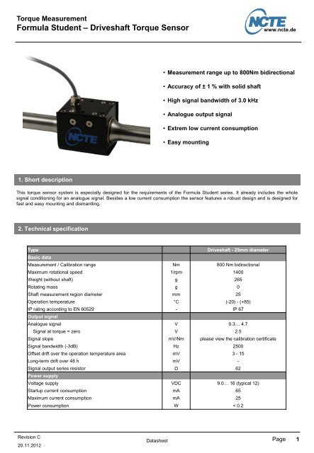
<strong>Torque</strong> Measurement<br />
<strong>Formula</strong> <strong>Stu<strong>de</strong>nt</strong> <strong>–</strong> <strong>Driveshaft</strong> <strong>Torque</strong> <strong>Sensor</strong><br />
1. Short <strong>de</strong>scription<br />
Revision C<br />
20.11.2012<br />
www.ncte.<strong>de</strong><br />
• Measurement range up to 800Nm bidirectional<br />
• Accuracy of ± 1 % with solid shaft<br />
• High signal bandwidth of 3.0 kHz<br />
• Analogue output signal<br />
• Extrem low current consumption<br />
• Easy mounting<br />
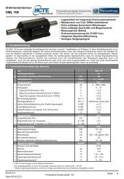
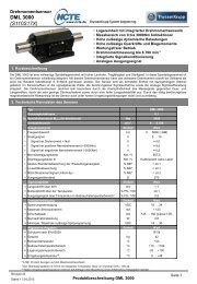
This torque sensor system is especially <strong>de</strong>signed for the requirements of the <strong>Formula</strong> <strong>Stu<strong>de</strong>nt</strong> series. It already inclu<strong>de</strong>s the whole<br />
signal conditioning for an analogue signal. Besi<strong>de</strong>s a low current consumption the sensor features a robust <strong>de</strong>sign and is <strong>de</strong>signed for<br />
fast and easy mounting and dismantling.<br />
2. Technical specification<br />
Type <strong>Driveshaft</strong> - 25mm diameter<br />
Basic data<br />
Measurement / Calibration range Nm 800 Nm bidirectional<br />
Maximum rotational speed 1/rpm 1400<br />
Weight (without shaft) g 265<br />
Rotating mass g 0<br />
Shaft measurement region diameter mm 25<br />
Operation temperature °C (-20) - (+85)<br />
IP rating according to EN 60529 - IP 67<br />
Output signal<br />
Analogue signal V 0.3… 4.7<br />
Signal at torque = zero V 2.5<br />
Signal slope mV/Nm please view the calibration certificate<br />
Signal bandwidth (-3dB) Hz 2500<br />
Offset drift over the operation temperature area mV 3 - 15<br />
Long-term drift over 48 h mV -<br />
Signal output series resistor Ω 62<br />
Power supply<br />
Voltage supply VDC 9.0… 16 (typical 12)<br />
Startup current consumption mA 65<br />
Maximum current consumption mA 25<br />
Power consumption W < 0.2<br />
Datasheet<br />
Page<br />
1
<strong>Torque</strong> Measurement<br />
<strong>Formula</strong> <strong>Stu<strong>de</strong>nt</strong> <strong>–</strong> <strong>Driveshaft</strong> <strong>Torque</strong> <strong>Sensor</strong><br />
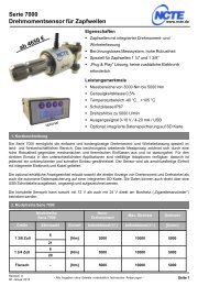
3. Dimension<br />
4. Pin assignment<br />
Revision C<br />
20.11.2012<br />
Supply & signal: 4-pin - screened<br />
Cable type: Unitronic 100 CY, 4 x 0,14mm 2<br />
Cable end: Prepared wires<br />
Datasheet<br />
Colour Short Description<br />
Brown Vcc Supply +<br />
Blue GND Supply ground<br />
Yellow A 0 Signal +<br />
Black A 0ref Signal ground<br />
www.ncte.<strong>de</strong><br />
Page<br />
2
<strong>Torque</strong> Measurement<br />
<strong>Formula</strong> <strong>Stu<strong>de</strong>nt</strong> <strong>–</strong> <strong>Driveshaft</strong> <strong>Torque</strong> <strong>Sensor</strong><br />
5. Handling Instruction / Assembly<br />
Transportation<br />
During sensor handling, storage and transportation it is to avoid that the<br />
sensor get close to high magnetic fields (e.g. magnets, electric motors).<br />
Furthermore static or dynamic loads must not be applied to the sensor<br />
especially the shaft.<br />
Handling<br />
As the shaft is enco<strong>de</strong>d and calibrated and therefore a part of the sensor<br />
system the co<strong>de</strong>d region on the shaft must not get in contact with metal<br />
parts. In addition any load which leads to a plastic <strong>de</strong>formation is<br />
forbid<strong>de</strong>n.<br />
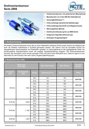
Assembly<br />
As shown in the illustration on the right the sensor will mounted and<br />
dismantled with aid of 8 screws. The screws marked as (1) fix the two<br />
sensor housing half-shells, the screws marked as (2) attach the shielding<br />
to the sensor housing. Due to the shielding have an magnetic function it‘s<br />
not recommen<strong>de</strong>d to use the sensor without it. Furthermore it is important<br />
to check the positions of the friction bearing shells during assembly to<br />
avoid additional load to the shaft and the bearings itself.<br />
Attention: Due to the specified protection class it is not<br />
allowed to open the screws of the cover and the<br />
cable connection.<br />
6. Contact<br />
NCTEngineering GmbH<br />
Erlenhof-Park<br />
Inselkammerstr. 4<br />
82008 Unterhaching<br />
Deutschland<br />
Tel.:+ 49 89 665619-0<br />
Fax:+ 49 89 665619-29<br />
Email: info@ncte.<strong>de</strong><br />
Revision C<br />
20.11.2012<br />
Datasheet<br />
Contact person:<br />
Motorsport Sales:<br />
Florian Müller<br />
Tel.:+ 49 89 665619-18<br />
Email: Florian.Mueller@ncte.<strong>de</strong><br />
www.ncte.<strong>de</strong><br />
1<br />
Page<br />
2<br />
3