3-Way Temperature Control Valve - Amot
3-Way Temperature Control Valve - Amot
3-Way Temperature Control Valve - Amot

You also want an ePaper? Increase the reach of your titles
YUMPU automatically turns print PDFs into web optimized ePapers that Google loves.
Typical applications<br />
For engines, turbines, gearboxes<br />
and heat exchangers:<br />
l Charge air cooling<br />
l Secondary cooling systems<br />
l Fuel and lube oil preheating<br />
l Co-generation<br />
l Engine jacket water<br />
For refineries, chemical plants<br />
and oil reproduction:<br />
l Waste heat boilers<br />
l Product coolers<br />
l Product heaters<br />
l Product condensers<br />
Key benefits<br />
l Ease of integration - valve size matches<br />
pipe size, resulting in reduced installation<br />
time and installation costs<br />
l Flexible design - ports can be configured<br />
to suit installation<br />
l Low pressure drop - compared to other valve<br />
types<br />
l Small physical size<br />
l Hand wheel allows manual adjustment of valve<br />
(optional on pneumatic valve) - simplified set<br />
up and maintenance<br />
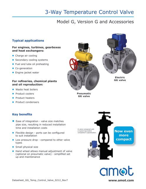
3-<strong>Way</strong> <strong>Temperature</strong> <strong>Control</strong> <strong>Valve</strong><br />
Model G, Version G and Accessories<br />
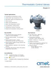
Pneumatic<br />
GG valve<br />
G valve compared with<br />
a typical equivalent<br />
competitor’s specification.<br />
Electric<br />
GG valve<br />
Now even<br />
more<br />
compact<br />
Datasheet_GG_Temp_<strong>Control</strong>_<strong>Valve</strong>_0212_Rev7 www.amot.com
3-<strong>Way</strong> <strong>Temperature</strong> <strong>Control</strong> <strong>Valve</strong> - Model G, Version G<br />
Datasheet_GG_Temp_<strong>Control</strong>_<strong>Valve</strong>_0212_rev7<br />
Contents<br />
Overview ..................................................... 3<br />
Applications .............................................. 3<br />
System Types .............................................. 4<br />
Overview of <strong>Valve</strong> Body ............................ 6<br />
Specification ............................................ 6<br />
Modes of Operation .................................. 7<br />
<strong>Valve</strong> Sizing .............................................. 9<br />
Dimensions ................................................ 13<br />
Overview of Electric Actuation ................... 15<br />
Electronic Positioner ................................. 16<br />
Overview of Pneumatic Actuation .............. 16<br />
How to Order ............................................. 17<br />
Accessories ............................................... 18<br />
PID <strong>Control</strong>ler 8071D, 8072D, SSR 47581.... 18<br />
3-Wire PT 100 <strong>Temperature</strong> Sensor 8060 ..... 18<br />
Solid State Relay Module 8073C ................. 19<br />
Electro Pneumatic Converter 8064A ............ 19<br />
Electro Pneumatic Converter 8064C ............ 20<br />
Pneumatic Indicator <strong>Control</strong>ler SG80 .......... 20<br />
page 2
3-<strong>Way</strong> <strong>Temperature</strong> <strong>Control</strong> <strong>Valve</strong> - Model G, Version G<br />
Overview<br />
AMOT G valves are 3-way control valves<br />
consisting of a heavy duty rotary valve and<br />
either a quarter turn electric or pneumatic<br />
actuator. The valves provide a high degree<br />
of accuracy and repeatability for accurate<br />
temperature control and are equally accurate<br />
in mixing or diverting service over a wide flow<br />
range.<br />
The heavy duty rotor design provides tight<br />
temperature control without high maintenance<br />
requirements. The system is available in three<br />
standard control configurations: electric;<br />
pneumatic; and electro-pneumatic, offering<br />
flexibility for most requirements. Designed<br />
Applications<br />
Mixing Applications<br />
Diverting Applications<br />
Charge Air <strong>Temperature</strong> <strong>Control</strong><br />
Datasheet_GG_Temp_<strong>Control</strong>_<strong>Valve</strong>_0212_rev7<br />
for high vibration service, the AMOT G valves<br />
are qualified to Lloyd’s Marine Requirements for<br />
shipboard service. <strong>Valve</strong>s can be directly mounted<br />
to reciprocating machinery, such as diesel<br />
engines, without vibration isolation. The heavy<br />
duty actuators are specially reinforced to provide<br />
vibration resistance.<br />
The standard valves are suitable for a variety<br />
of fluids such as water, water/glycol, sea water,<br />
lubricating and hydraulic oils. Optional body<br />
materials are available for services involving<br />
synthetic or fire resistant oils, deionized water and<br />
ammonia or freon in oil.<br />
Lubricating oil temperature control is normally<br />
configured in a mixing application controlling<br />
the return temperature to the heat load. The<br />
temperature is normally measured as close as<br />
possible to the sump return.<br />
Jacket water cooling in diverting applications<br />
regulates the outlet coolant water temperature<br />
from a diesel or gas engine. The valve either<br />
sends water to a cooler or bypass loop, accurately<br />
maintaining the temperature.<br />
The temperature is normally measured at the<br />
outlet from the heat source.<br />
The intercooler is used to cool high temperature<br />
turbo charger air.<br />
In this application the G <strong>Valve</strong> regulates the flow<br />
of cooling water through an intercooler, increasing<br />
efficiency, enhancing performance and helping to<br />
meet today’s environmental requirements.<br />
page 3
3-<strong>Way</strong> <strong>Temperature</strong> <strong>Control</strong> <strong>Valve</strong> - Model G, Version G<br />
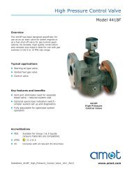
System Types<br />
Electric <strong>Valve</strong><br />
Electric System<br />
<strong>Temperature</strong><br />
Probe 8060<br />
PID <strong>Control</strong>ler 8071/2D,<br />
IP67 enclosure<br />
Electric<br />
GG <strong>Valve</strong><br />
GG <strong>Valve</strong><br />
Datasheet_GG_Temp_<strong>Control</strong>_<strong>Valve</strong>_0212_rev7<br />
For the electric valve, the actuator of the G valve<br />
assembly uses an electric motor which rotates<br />
in either direction in response to the ON-OFF<br />
signals received. The motor drives a gearbox<br />
connected to the rotor shaft and turns the valve<br />
rotor clockwise or counter-clockwise, a maximum<br />
of 90 degrees. At the end of travel, limit switches<br />
are incorporated to isolate the electrical supply to<br />
the motor when the valve rotor has reached either<br />
end of the rotation. A feedback potentiometer is<br />
standard and provides position indication to the<br />
control system.<br />
The electric actuator is a rugged, compact and<br />
lightweight quarter turn actuator having enclosure<br />
protection to IP65.<br />
The actuator is powered by an electric motor<br />
driving a worm-type gearbox. The worm gearbox<br />
prevents reverse drive due to fluid forces. It is<br />
fitted with manual override as standard, enabling<br />
valve operation without power.<br />
A thermal cutout is fitted preventing overheating.<br />
Limit switches at each end of stroke disconnect<br />
motor power when end stroke is reached. These<br />
can also be used for remote indication.<br />
See page 15 for more information on the electric<br />
actuator.<br />
The electric valve system incorporates the use of<br />
an electrically actuated three-way control valve<br />
with an electronic controller. The 8071D PID<br />
<strong>Control</strong>ler can be either panel or wall mounted<br />
(see page 18 for more information). The system<br />
is completed with a temperature sensor type 8060<br />
(see page 18 for details).<br />
The electric G <strong>Valve</strong> system is simple to install<br />
with standard four core cable, and provides more<br />
accurate measurement and control than typical<br />
pneumatically operated systems.<br />
page 4
3-<strong>Way</strong> <strong>Temperature</strong> <strong>Control</strong> <strong>Valve</strong> - Model G, Version G<br />
System Types continued<br />
Pneumatic <strong>Valve</strong> The pneumatic valve uses a spring return<br />
pneumatic actuator and positioner to control the<br />
rotation of the valve in response to an input signal<br />
from a pneumatic or electro-pneumatic control<br />
system. The pneumatic control system sends a<br />
pneumatic signal ranging from 0.21 to 1.03 bar<br />
(3 to 15 psi) to the actuator to correctly position<br />
Pneumatic System<br />
SG80 <strong>Temperature</strong><br />
<strong>Control</strong>ler and Sensor<br />
Electro-Pneumatic System The electro-pneumatic valve system combines<br />
both electric and pneumatic technology, consisting<br />
of a pneumatically actuated three-way control<br />
valve with an electro-pneumatic converter, type<br />
8064A. See page 19 for more details.<br />
<strong>Temperature</strong><br />
Probe<br />
8060<br />
<strong>Temperature</strong><br />
<strong>Control</strong>ler<br />
8071D<br />
Pneumatic<br />
GG <strong>Valve</strong><br />
Electro-Pneumatic<br />
Converter<br />
8064A<br />
GG <strong>Valve</strong><br />
GG <strong>Valve</strong><br />
Datasheet_GG_Temp_<strong>Control</strong>_<strong>Valve</strong>_0212_rev7<br />
the valve at the desired temperature setting. The<br />
pneumatic control system usually consists of a P+I<br />
pneumatic controller, sensor and the necessary air<br />
supply conditioning equipment (regulators, filters<br />
and water traps).<br />
The pneumatic actuator is a rugged, quarter turn,<br />
double piston actuator operating on a scotch yoke<br />
principle.<br />
The actuator is fitted with spring return as<br />
standard allowing fail-safe configuration if<br />
necessary. It is also fitted with a valve positioner<br />
enabling accurate and repeatable movement.<br />
See page 16 for more information on the<br />
pneumatic actuator.<br />
The pneumatic valve system incorporates a<br />
pneumatically actuated three-way control valve<br />
with controller and integral temperature sensor,<br />
the SG80, which can be panel or wall mounted.<br />
For more information on the SG80, see page 20.<br />
The pneumatic G valve system is ideal when there<br />
is a lack of electricity or when a fail-safe system is<br />
needed.<br />
The probe sends a resistance signal to the<br />
electronic controller, which in turn sends a 4 to<br />
20mA signal to an I/P converter that converts this<br />
to a pneumatic signal.<br />
The electro-pneumatic system combines the<br />
features and functionality of the AMOT electronic<br />
control system with the fail-safe action benefits of<br />
a pneumatically actuated valve.<br />
page 5
3-<strong>Way</strong> <strong>Temperature</strong> <strong>Control</strong> <strong>Valve</strong> - Model G, Version G<br />
Overview of <strong>Valve</strong> Body<br />
Specification<br />
<strong>Valve</strong> Body<br />
Flow to: 720m 3 /hr 3,170 US gpm<br />
For valves with higher flow rates see datasheet GEF_GPD_Temp_<strong>Control</strong>_<strong>Valve</strong><br />
Sizes: Standard flow High flow<br />
Datasheet_GG_Temp_<strong>Control</strong>_<strong>Valve</strong>_0212_rev7<br />
80mm - 200mm (3” - 8”) 80mm - 200mm (3” - 8”)<br />
For 50 mm (2”) and for 350 mm (14”) and above see Datasheet<br />
GEF_GPD_Temp_<strong>Control</strong>_<strong>Valve</strong> for data<br />
Body/rotor materials: Bronze For seawater, shock resistance, or<br />
magnetic permeability<br />
Seal material: Flourocarbon (Viton, FKM)<br />
Ductile iron High performance iron, for fresh<br />
water, lubricating oils<br />
Steel For high strength and high pressure<br />
ratings<br />
Stainless steel Corrosive and special applications<br />
Flanges: EN 1092, ASME and JIS standards.<br />
Maximum internal Ductile iron or bronze 10 bar (145 psi)<br />
valve pressure: Steel and stainless steel 16 bar (232 psi)<br />
Maximum temperature 100°C (212°F)<br />
of fluid:<br />
Vibration: Exceeds the requirements of Lloyd’s Register Type Approval System,<br />
Test Specification Number 1, 2002, Vibration Test 2.<br />
For both electric and pneumatic:<br />
Frequency<br />
range<br />
Key features and benefits<br />
l Lightweight and compact<br />
Displacement Acceleration Lloyd’s<br />
5 - 25 Hz +/- 1.6mm +/- 1.6mm<br />
25 - 100 Hz +/- 5.0g (49 m/s 2 ) +/- 4.0g (39 m/s 2 )<br />
100 - 300 Hz +/- 1.0g (9.81 m/s 2 ) 90<br />
minute<br />
l Configurable ports - allowing flexibility on<br />
installation<br />
l Low pressure drop - enables savings on<br />
either valve or pump size<br />
l High accuracy providing better temperature<br />
control<br />
No requirement<br />
page 6
3-<strong>Way</strong> <strong>Temperature</strong> <strong>Control</strong> <strong>Valve</strong> - Model G, Version G<br />
Modes of Operation - Electrically Actuated<br />
1<br />
2<br />
3<br />
e<br />
d<br />
o<br />
M<br />
1<br />
2<br />
e<br />
d<br />
o<br />
M<br />
2<br />
1<br />
e<br />
d<br />
o<br />
M<br />
3<br />
2<br />
e<br />
d<br />
o<br />
M<br />
3<br />
1<br />
e<br />
d<br />
o<br />
M<br />
1<br />
3<br />
e<br />
d<br />
o<br />
M<br />
2<br />
Electric actuator<br />
(switched live input)<br />
Datasheet_GG_Temp_<strong>Control</strong>_<strong>Valve</strong>_0212_rev7<br />
3<br />
The unique construction of the AMOT G valve provides total<br />
flexibility by allowing you to select the valve port positions most<br />
ideally suited to meet your application requirements. There are<br />
two main types of mode of operation: 90° rotor that allows<br />
either ports 1 or 3 to be selected as the common port; and<br />
180° rotor that requires port 2 to be the common port. Arrow<br />
indicates valve movement with increasing temperature or mA,<br />
as viewed from above (see diagram). For electrically actuated<br />
valves, on loss of signal the actuator is set up by default to<br />
stop in its current position.<br />
Electric actuator direct acting<br />
(4-20mA input)<br />
Electric actuator reverse acting<br />
(20-4mA input)<br />
Cold position Hot position 4mA (cold) 20mA (hot) 20mA (cold) 4mA (hot)<br />
page 7
3-<strong>Way</strong> <strong>Temperature</strong> <strong>Control</strong> <strong>Valve</strong> - Model G, Version G<br />
Modes of Operation - Pneumatically Actuated<br />
1<br />
2<br />
3<br />
e<br />
d<br />
o<br />
M<br />
1<br />
2<br />
e<br />
d<br />
o<br />
M<br />
2<br />
1<br />
e<br />
d<br />
o<br />
M<br />
3<br />
2<br />
e<br />
d<br />
o<br />
M<br />
3<br />
1<br />
e<br />
d<br />
o<br />
M<br />
1<br />
3<br />
e<br />
d<br />
o<br />
M<br />
2<br />
Datasheet_GG_Temp_<strong>Control</strong>_<strong>Valve</strong>_0212_rev7<br />
3<br />
The unique construction of the AMOT G valve<br />
provides total flexibility by allowing you to select<br />
the valve port positions most ideally suited to<br />
meet your application requirements. There are two<br />
main types of mode of operation: 90° rotor that<br />
allows either ports 1 or 3 to be selected as the<br />
common port; and 180° rotor that requires port<br />
2 to be the common port. Arrow indicates valve<br />
movement with increasing temperature or mA, as<br />
viewed from above (see diagram).<br />
Pneumatic actuator direct acting Pneumatic actuator reverse acting<br />
3 PSI (cold) 15 PSI (hot) No signal 15 PSI (cold) 3 PSI (hot) No signal<br />
page 8
3-<strong>Way</strong> <strong>Temperature</strong> <strong>Control</strong> <strong>Valve</strong> - Model G, Version G<br />
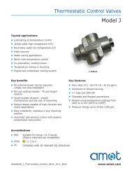
<strong>Valve</strong> Sizing (Metric units)<br />
<strong>Valve</strong> Flowrate Selection (Flowrate m 3 /hr)<br />
Size DN (inches)<br />
Pressure drop bar<br />
0<br />
Standard High<br />
s s<br />
flow flow<br />
s<br />
s s s s s s<br />
50 (2)<br />
Currently only available in GEF/GPD versions. See Datasheet GEF_GPD_Temp_<strong>Control</strong>_<strong>Valve</strong> for data<br />
80 (3) 7 14 20 26 33 39 46 52<br />
100 (4) 80 (3) 19 35 51 67 83 99 115 131<br />
150 (6) 100 (4) 29 54 79 104 129 154 179 204<br />
200 (8) 150 (6) 66 122 178 235 291 347 403 459<br />
250 (10)<br />
0.40<br />
0.35<br />
0.30<br />
0.25<br />
0.20<br />
0.15<br />
0.10<br />
0.05<br />
300 (12) 250 (10)<br />
350 (14) 300 (12)<br />
400 (16) 350 (14)<br />
450 (18) 400 (16)<br />
1 – Water<br />
2 – ISO VG32<br />
3 – ISO VG46<br />
4 – ISO VG68<br />
<strong>Valve</strong> selection curves for valves<br />
with 90 o rotor. For valves with 180 o<br />
rotor multiply pressure drops by 2.<br />
Recommended maximum pressure drop<br />
200 (8) 118 218 318 418 517 617 717 817<br />
Datasheet_GG_Temp_<strong>Control</strong>_<strong>Valve</strong>_0212_rev7<br />
4 3 2<br />
1<br />
AMOT type G valves are designed to produce minimal pressure<br />
drop. The normal recommendation in sizing the valves is to<br />
select a pressure drop between 0.01 to 0.3 bar (0.15 and<br />
4.5 psi).<br />
Currently only available in GEF/GPD versions.<br />
See Datasheet GEF_GPD_Temp_<strong>Control</strong>_<strong>Valve</strong> for data<br />
To use the graph it is advised to use the following method:<br />
1. Start with a pressure drop of 0.05 bar on<br />
the vertical axis, read across to the curve.<br />
2. Follow this line down to the flow rates below<br />
until you find the value closest to your flow rate.<br />
3. Follow the line across to the left to determine<br />
suitable valve size.<br />
For stable control the valve should be selected so as to provide<br />
a pressure drop with full flow of between 0.01 and 0.3 bar<br />
(0.15 and 4.5 psi).<br />
page 9
3-<strong>Way</strong> <strong>Temperature</strong> <strong>Control</strong> <strong>Valve</strong> - Model G, Version G<br />
<strong>Valve</strong> Sizing (English units)<br />
<strong>Valve</strong> Flowrate Selection (Flowrate USg/m)<br />
Size inches (DN)<br />
s<br />
Pressure drop psi<br />
2 (50)<br />
s s s s s s s s<br />
3 (80) 31 62 88 114 145 172 203 229<br />
4 (100) 3 (80) 84 154 225 295 365 436 506 577<br />
6 (150) 4 (100) 128 238 348 458 568 678 788 898<br />
8 (200) 6 (150) 291 537 784 1035 1281 1528 1774 2021<br />
10 (250)<br />
5.08<br />
4.35<br />
3.62<br />
2.90<br />
2.18<br />
1.45<br />
0.73<br />
0<br />
Standard High<br />
flow flow<br />
12 (300) 10 (250)<br />
14 (350) 12 (300)<br />
16 (400) 14 (350)<br />
18 (450) 16 (400)<br />
1 – Water<br />
2 – ISO VG32<br />
3 – ISO VG46<br />
4 – ISO VG68<br />
<strong>Valve</strong> selection curves for valves<br />
with 90 o rotor. For valves with 180 o<br />
rotor multiply pressure drops by 2.<br />
Recommended maximum pressure drop<br />
8 (200) 520 960 1400 1840 2276 2717 3157 3597<br />
Datasheet_GG_Temp_<strong>Control</strong>_<strong>Valve</strong>_0212_rev7<br />
4 3 2<br />
AMOT type G valves are designed to produce minimal pressure<br />
drop. The normal recommendation in sizing the valves is to select<br />
a pressure drop between 0.15 and 4.5 psi (0.01 to 0.3 bar).<br />
To use the graph it is advised to use the following method:<br />
1. Start with a pressure drop of 0.5 psi on the vertical axis,<br />
read across to the curve.<br />
2. Follow this line down to the flow rates below until you find<br />
the value closest to your flow rate.<br />
3. Follow the line across to the left to determine suitable<br />
valve size.<br />
For stable control the valve should be selected so as to provide a<br />
pressure drop with full flow of between 0.15 and 4.5 psi (0.01<br />
and 0.3 bar).<br />
Currently only available in GEF/GPD versions. See Datasheet GEF_GPD_Temp_<strong>Control</strong>_<strong>Valve</strong> for data<br />
Currently only available in GEF/GPD versions.<br />
See Datasheet GEF_GPD_Temp_<strong>Control</strong>_<strong>Valve</strong> for data<br />
1<br />
page 10
Correction Factor<br />
3-<strong>Way</strong> <strong>Temperature</strong> <strong>Control</strong> <strong>Valve</strong> - Model G, Version G<br />
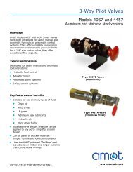
<strong>Valve</strong> Sizing<br />
Viscosity Correction<br />
Example:<br />
From the graph below:<br />
100 cSt = correction factor of 0.68<br />
0.68 x flow coefficient = corrected flow<br />
coefficient (Kv or Cv)<br />
Some approximate viscosities (cSt) of<br />
SAE oils at 40°C (110°F) are shown<br />
below, based on leading oil manufacturers<br />
published data.<br />
Viscosity Correction Curve (Fv)<br />
SAE Oil Viscosities<br />
Engine oils<br />
Oil cSt<br />
SAE 5W 6.8<br />
SAE 10W 32<br />
SAE 20 46<br />
SAE 20W 68<br />
SAE 30 100<br />
SAE 40 150<br />
SAE 50 220<br />
Viscosity (Centistokes)<br />
Gear oils<br />
Oil cSt<br />
SAE 75W 22<br />
SAE 80W 46<br />
SAE 85W 100<br />
SAE 90 150<br />
SAE 140 460<br />
Datasheet_GG_Temp_<strong>Control</strong>_<strong>Valve</strong>_0212_rev7<br />
For the selection of valves for more viscous fluids<br />
than water, the following must be calculated:<br />
Viscosity: Find the viscosity of the fluid in which<br />
the valve is to operate. The viscosity is normally<br />
expressed in centistokes. Where ISO oil is used,<br />
the grade number is also the viscosity eg ISO<br />
VG46 is 46 centistokes at 40°C (104°F).<br />
Viscosity correction: By using the correction graph<br />
below, the flow coefficient correction factor can be<br />
established. The correction figure obtained from<br />
the graph should then be multiplied by the original<br />
flow coefficient which can then be used in the<br />
standard valve sizing formulae.<br />
Some approximate viscosities (cSt) of SAE oils at<br />
40°C (104°F) are shown below, based on leading<br />
oil manufacturers’ published data.<br />
page 11
3-<strong>Way</strong> <strong>Temperature</strong> <strong>Control</strong> <strong>Valve</strong> - Model G, Version G<br />
<strong>Valve</strong> Sizing<br />
<strong>Valve</strong> Sizing Calculations<br />
<strong>Valve</strong> Flowrate<br />
See the table below for examples of Kv and Cv:<br />
Size<br />
DN<br />
(in)<br />
Standard<br />
flow<br />
High<br />
flow<br />
50<br />
(2)<br />
80<br />
(3)<br />
100<br />
(4)<br />
80<br />
(3)<br />
150<br />
(6)<br />
100<br />
(4)<br />
200<br />
(8)<br />
150<br />
(6)<br />
200<br />
(8)<br />
Kv 82 207 323 729 1296<br />
Cv 96 242 378 851 1513<br />
Currently only available in GEF/GPD versions.<br />
See Datasheet GEF_GPD_Temp_<strong>Control</strong>_<strong>Valve</strong> for data<br />
<strong>Valve</strong> Bypass Flowrates<br />
250<br />
(10)<br />
The AMOT G <strong>Valve</strong> is not a tight shutoff valve.<br />
When used in a reasonably balanced pressure<br />
system there will be some small amounts of<br />
leakage between ports. The actual amount of<br />
leakage will vary with the pressure difference<br />
300<br />
(12)<br />
250<br />
(10)<br />
Datasheet_GG_Temp_<strong>Control</strong>_<strong>Valve</strong>_0212_rev7<br />
350<br />
(14)<br />
300<br />
(12)<br />
400<br />
(16)<br />
350<br />
(14)<br />
450<br />
(18)<br />
400<br />
(16)<br />
Pressure Drop<br />
The G valve is designed to produce<br />
minimal pressure drop. The normal<br />
recommendation when determining<br />
the size of an AMOT G valve is a<br />
pressure drop between 0.01 and 0.3<br />
bar (1.5 and 4.5 psi). Note: Kv and<br />
Cv values are applicable to 90° rotor<br />
versions only.<br />
Kv is the flow coefficient in metric units. It is defined as the flow rate in cubic meters per hour (m 3 /h) of water at a<br />
temperature of 16º celsius with a pressure drop across the valve of 1 bar. Cv is the imperial coefficient. It is defined<br />
as the flow rate in US Gallons per minute [gpm] of water at a temperature of 60º fahrenheit with a pressure drop<br />
across the valve of 1 psi. (Kv = 0.865 Cv / Cv = 1.156 Kv)<br />
The basic formula to determine the Kv of a valve is:<br />
Kv = Q<br />
SG<br />
Dp<br />
Q = Flow (m 3 /h)<br />
Dp = Pressure drop (bar)<br />
SG = Specific gravity of fluid<br />
Kv = <strong>Valve</strong> flow coefficient<br />
There are two other ways that this formula can be used to<br />
find the flow in m 3 /h or pressure drop of a valve in bar:<br />
Q = Kv<br />
Dp<br />
SG<br />
2<br />
Q<br />
Dp = SG<br />
Kv<br />
The basic formula to determine the Cv of a valve is:<br />
Cv = Q<br />
SG<br />
Dp<br />
There are two other ways that this formula can be used to<br />
find the flow in US gallons/minute or pressure drop of a<br />
valve in PSI:<br />
Q = Cv<br />
Dp<br />
SG<br />
Q = Flow (US gallons/min)<br />
Dp = Pressure drop (psi)<br />
SG = Specific gravity of fluid<br />
Cv = <strong>Valve</strong> flow coefficient<br />
2<br />
Q<br />
Dp = SG<br />
Cv<br />
between these ports. Consult AMOT for further<br />
information if the application is sensitive to<br />
leakage rates or if high pressure differences are<br />
likely to occur.<br />
page 12
3-<strong>Way</strong> <strong>Temperature</strong> <strong>Control</strong> <strong>Valve</strong> - Model G, Version G<br />
Dimensions<br />
Electrically Actuated with<br />
Manual Override<br />
Pneumatically<br />
Actuated<br />
Pneumatically Actuated<br />
with Manual Override<br />
Datasheet_GG_Temp_<strong>Control</strong>_<strong>Valve</strong>_0212_rev7<br />
See page 14<br />
for dimensions<br />
page 13
3-<strong>Way</strong> <strong>Temperature</strong> <strong>Control</strong> <strong>Valve</strong> - Model G, Version G<br />
Dimensions continued<br />
Dimensions in mm<br />
<strong>Valve</strong> Type<br />
<strong>Valve</strong> Body<br />
Electrically Actuated<br />
NB A B C D E S T U V W X Y Z R* S* T* U* V* W X Y Z<br />
03GGS 207 200 107 03GGS<br />
80 280 140<br />
03GGH 227 200 127 03GGH<br />
04GGS 242 229 128 95 123 100 52 52 226 202 95 53 04GGS<br />
100 300 150<br />
04GGH 281 224 169 04GGH<br />
195 140 68 54 260 76 142 147<br />
06GGS 312 285 169 06GGS<br />
150 370 185<br />
06GGH 346 285 191 100 06GGH<br />
08GGS 371 343 191 155 200 45 79 276 358 115 53 08GGS<br />
200 450 225<br />
113<br />
08GGH 418 340 253 08GGH<br />
Dimensions in inches<br />
<strong>Valve</strong> Type<br />
NB A B C D E S T U V W X Y Z R* S* T* U* V* W X Y Z<br />
03GGS 8.150 7.874 4.213 03GGS<br />
3 11.024 5.512<br />
03GGH 8.937 7.874 5.000 03GGH<br />
04GGS 9.528 9.016 5.039 3.740 4.843 3.937 2.047 2.047 8.898 7.953 3.740 2.087 04GGS<br />
4 11.811 5.906<br />
04GGH 11.063 8.819 6.654 04GGH<br />
7.677 5.512 2.677 2.126 10.236 2.992 5.591 5.787<br />
06GGS 12.283 11.220 6.654 06GGS<br />
6 14.567 7.283<br />
06GGH 13.622 11.220 7.520 3.937 06GGH<br />
08GGS 14.606 13.504 7.520 6.102 7.874 1.772 3.110 10.866 14.094 4.528 2.087 08GGS<br />
8 17.717 8.858<br />
4.449<br />
08GGH 16.457 13.386 9.961 08GGH<br />
Datasheet_GG_Temp_<strong>Control</strong>_<strong>Valve</strong>_0212_rev7<br />
Pneumatically Actuated<br />
<strong>Valve</strong> Body Electrically Actuated Pneumatically Actuated<br />
* Relevant only to pneumatic actuator with manual override version<br />
Bolthole dimensions are as per the relevant specification chosen in the model<br />
coding. Full dimensional details can be provided on request.<br />
<strong>Valve</strong> Type<br />
<strong>Valve</strong> Type<br />
page 14
3-<strong>Way</strong> <strong>Temperature</strong> <strong>Control</strong> <strong>Valve</strong> - Model G, Version G<br />
Overview of Electric Actuation<br />
Specification<br />
Electric Actuator<br />
Datasheet_GG_Temp_<strong>Control</strong>_<strong>Valve</strong>_0212_rev7<br />
Key features and benefits<br />
l Self-locking with minimum backlash in the<br />
transmission - prevents valve movement<br />
due to flow<br />
l Auxiliary limit switches for user connection<br />
l Manual override fitted as standard - valve<br />
can be operated in event of power failure<br />
l Two torque switches - provide protection in<br />
event of actuator overloading<br />
Power 115V ± 10% or 230V ± 10% 50/60Hz single phase<br />
Limit switches Two open/close SPDT 250V AC, 10A<br />
Motor thermal protection Fitted as standard<br />
Angular rotation 110° max Quarter turn<br />
High reliability contactless Optional 1 k ohm or 5 k ohm potentiometers<br />
Hall effect sensor<br />
Cable entry 2 x M25 x 1.5 IP68 glands provided<br />
Mechanical stop Two adjustable screws<br />
Manual override Fitted as standard<br />
Materials Steel, aluminum alloy, aluminum bronze, polycarbonate<br />
External coating Dry powder polyester<br />
Weatherproof enclosure IP67, NEMA 4 and 6<br />
Ambient temperature -20°C to +85°C (-4°F to +185°F)<br />
Ambient humidity 90% RH max (non-condensing)<br />
Anti-condensation heater 7 - 10W<br />
Vibration resistance 5 - 100 Hz 5g<br />
100 - 300 Hz 1g<br />
Performance Duty cycle 20°C Stroke time (secs) Max currrent (A)<br />
Standard High flow 50 Hz 60 Hz 220V 110V<br />
50 Currently only available in GEF/GPD versions. See Datasheet GEF_GPD_Temp_<strong>Control</strong>_<strong>Valve</strong> for data<br />
80 - 200 80 - 200 65% 25 21 0.88 1.7<br />
250 - 450 250 - 400 Currently only available in GEF/GPD versions. See Datasheet GEF_GPD_Temp_<strong>Control</strong>_<strong>Valve</strong> for data<br />
page 15
3-<strong>Way</strong> <strong>Temperature</strong> <strong>Control</strong> <strong>Valve</strong> - Model G, Version G<br />
Electronic Positioner<br />
The AMOT actuator/valve positioner is configured<br />
to accept an industry standard 4-20mA position<br />
demand input signal, and uses this to operate<br />
internal solid state switching to drive the motor.<br />
The microprocessor based unit uses the signal<br />
from the contactless position sensor to accurately<br />
position the actuator, taking into account motor<br />
response time and actuator overshoot.<br />
The positioner is split into two parts, housed in the<br />
terminal box. There is a power module, in which<br />
all high voltage circuits are fully encapsulated to<br />
withstand high vibration, and a control board. This<br />
design allows for easy maintenance.<br />
Overview of Pneumatic Actuation<br />
Specification<br />
Electronic Positioner<br />
Pneumatic Actuator<br />
Datasheet_GG_Temp_<strong>Control</strong>_<strong>Valve</strong>_0212_rev7<br />
User configuration allows:<br />
l The input can be selected from 4-20mA,<br />
0-20mA, 0-5V, 0-10V and 2-10V by switches.<br />
l 4-20mA output, which shows actual valve<br />
position, can be configured to retransmit the<br />
demand input signal.<br />
l A switch allows for easy configuration of<br />
which end of stroke corresponds with a<br />
4mA demand.<br />
l The action on sensor fail can be selected<br />
from moving to either the 4mA or the 20mA<br />
positions, but is factory set to not moving.<br />
l The deadband can be increased to aid<br />
performance with noisy input signals.<br />
l When necessary, such as after maintenance,<br />
the actuator can be recalibrated at the touch<br />
of a button.<br />
Key features and benefits<br />
l A rugged quarter turn, double piston, rack<br />
and pinion pneumatic actuator with spring<br />
return and valve positioner as standard.<br />
l Can be configured fail-safe<br />
Housing Cast aluminum base, steel cover and two part Polyurethane paint finish.<br />
Supply pressure 6 to 8 bar (90 to 115 psi)<br />
Signal pressure 0.21 to 1.03 bar (3 to 15 psi)<br />
Pressure connections G 1/4 (1/4 NPT)<br />
Manual override Optional<br />
There are three LEDs on the terminal box on the<br />
side of the actuator, providing clear visual indication<br />
of actuator status. Two alarm outputs allow for<br />
remote fault monitoring.<br />
page 16
<strong>Valve</strong> Body Selection<br />
3-<strong>Way</strong> <strong>Temperature</strong> <strong>Control</strong> <strong>Valve</strong> - Model G, Version G<br />
How to Order<br />
Use the table below to select the unique specification of your G valve.<br />
Example Code<br />
Actuator Selection<br />
<strong>Valve</strong><br />
Size &<br />
Model<br />
<strong>Valve</strong> Flow<br />
Type<br />
<strong>Valve</strong> Body and<br />
Rotor Material<br />
Rotor Type<br />
06GG S D B S 32 EA B CA -AA Code Description<br />
Nominal Bore Size Comments<br />
02GG 2 Inch (DN50) Currently only available in GEF/GPD versions.<br />
03GG 3 Inch (DN80)<br />
04GG 4 Inch (DN100)<br />
06GG 6 Inch (DN150)<br />
08GG 8 Inch (DN200)<br />
10GG 10 Inch (DN250)<br />
12GG 12 Inch (DN300)<br />
14GG 14 Inch (DN350)<br />
16GG 16 Inch (DN400)<br />
18GG 18 Inch (DN450)<br />
<strong>Valve</strong> Flange<br />
Connection Standard<br />
and Class<br />
<strong>Valve</strong> Mode of Operation<br />
<strong>Valve</strong> Actuation Type<br />
Electric Actuator Power Supply<br />
Pneumatic Actuator Air<br />
Connections & Manual override<br />
Actuator <strong>Control</strong> Input Signal<br />
Actuator Feedback Signal<br />
Customer Special Options<br />
<strong>Valve</strong> Flow Type (Refer to flow coefficient table for Cv/Kv data)<br />
S Standard Flow <strong>Valve</strong><br />
H High Flow <strong>Valve</strong><br />
Body and Rotor Material<br />
B<br />
Bronze<br />
D<br />
Ductile Iron<br />
R<br />
Stainless Steel<br />
S<br />
Carbon Steel<br />
Flange Class Flange Standard Comments<br />
A PN6 EN 1092<br />
B PN10 EN 1092<br />
C PN16 EN 1092<br />
F 125 lb (Flat Face) ASME Ductile Iron <strong>Valve</strong>s Only<br />
J 150 lb ASME<br />
L 10K JIS<br />
M 5K JIS<br />
N 150 lb<br />
Rotor Type<br />
MIL-PRF-20042E Bronze <strong>Valve</strong>s Only<br />
S Standard Rotor<br />
Rotor Position Rotation Starting From<br />
Cold Process Hot Process Cold Position<br />
12 Port 1 Port 2<br />
23 Port 2 Port 3<br />
Clockwise<br />
31 Port 3 Port 1<br />
21 Port 2 Port 1<br />
32 Port 3 Port 2<br />
Anticlockwise<br />
13 Port 1 Port 3<br />
Power Supply Air Connection Manual override<br />
Datasheet_GG_Temp_<strong>Control</strong>_<strong>Valve</strong>_0212_rev7<br />
Elec<br />
Pneu<br />
EA<br />
EB<br />
100 -120 Vac 50/60Hz<br />
200 - 240 Vac 50/60Hz<br />
-<br />
-<br />
Fitted as Standard<br />
P1<br />
P2<br />
-<br />
-<br />
G1/4 (1/4" BSPP)<br />
1/4" NPT<br />
Not Fitted<br />
P3<br />
P4<br />
-<br />
-<br />
G1/4 (1/4" BSPP)<br />
1/4" NPT<br />
Fitted<br />
Input Signal<br />
Comments<br />
A<br />
Relays, Switched Live Supply<br />
B 4-20mA<br />
C<br />
1<br />
20-4mA<br />
3-15psi<br />
On Increasing <strong>Temperature</strong><br />
2 15-3psi<br />
Feedback Signal<br />
AA<br />
None<br />
BA<br />
0 - 1000Ω (via Potentiometer)<br />
CA<br />
4-20mA Position Retransmit<br />
DA<br />
4-20mA Position Retransmit and 0 - 1000Ω (via Potentiometer)<br />
EA<br />
20-4mA Position Retransmit<br />
FA<br />
20-4mA Position Retransmit and 0 - 1000Ω (via Potentiometer)<br />
Pne 00<br />
None<br />
Elec<br />
Pne<br />
Electric<br />
-AA<br />
-***<br />
Standard Product<br />
Customer Special Code Assigned<br />
Currently only available in<br />
GEF/GPD versions. See Datasheet<br />
GEF_GPD_Temp_<strong>Control</strong>_<strong>Valve</strong><br />
page 17
3-<strong>Way</strong> <strong>Temperature</strong> <strong>Control</strong> <strong>Valve</strong> - Model G, Version G<br />
Accessories<br />
PID <strong>Valve</strong> <strong>Control</strong>lers 8071/8072D and<br />
Solid State Relays 47581L001<br />
PID <strong>Control</strong>ler<br />
8072D<br />
Solid State<br />
Relay<br />
47581L001<br />
PID <strong>Control</strong>ler<br />
8071D<br />
For further information and how to order these products see<br />
Datasheet_8071_2_D_47851.pdf<br />
3-Wire PT100 <strong>Temperature</strong> Sensor - 8060<br />
<strong>Temperature</strong> Sensor<br />
8060<br />
Datasheet_GG_Temp_<strong>Control</strong>_<strong>Valve</strong>_0212_rev7<br />
Key features and benefits<br />
l Fully programmable PID-based control<br />
- allows easy system configuration<br />
l Universal inputs; RTD’s, thermocouple, or<br />
standard 4-20mA signal gives maximum system<br />
design flexibility<br />
l Can be operated in manual mode - easy<br />
maintenance and set up<br />
Key features and benefits<br />
l 3 wire RTDs - accurate temperature<br />
measurement<br />
l Excellent long term stability<br />
l Good linearity<br />
For further information and how to order this product see<br />
Datasheet_8060_temp_sensor.pdf<br />
l Can use standard 3-core cable<br />
page 18
3-<strong>Way</strong> <strong>Temperature</strong> <strong>Control</strong> <strong>Valve</strong> - Model G, Version G<br />
Accessories<br />
Solid State Relay Module - 8073C<br />
Typical Applications<br />
Logic outputs<br />
Relay Module<br />
8073C<br />
Datasheet_GG_Temp_<strong>Control</strong>_<strong>Valve</strong>_0212_rev7<br />
Key features and benefits<br />
l IP67 enclosure<br />
l Alternative to using two SSRs type<br />
47581L001<br />
l Good linearity<br />
The 8073C relay module incorporates two solid<br />
state relays with terminations in an IP67 enclosure.<br />
The 8073C is designed to be used with the 8071D<br />
controller logic outputs to drive voltages for the<br />
electrically actuated G valve. Features include: zerocrossing<br />
switching, relay and logic level inputs and<br />
IP67 enclosure.<br />
AC inputs<br />
110/240 Vac<br />
110/240 Vac<br />
Interface with 8071D controller Interface with AC input signals<br />
For further information and how to order this product see<br />
Datasheet_8073C_SSR.pdf<br />
Electro-Pneumatic Converter - 8064A<br />
Key features and benefits<br />
Electro-Pneumatic<br />
Converter - 8064A<br />
l High vibration resistance - Lloyds 4G<br />
l Suitable for longer pipe runs<br />
l Fully adjustable for optimised system<br />
operation<br />
l Can use standard 3-core cable<br />
Typical Application<br />
<strong>Temperature</strong><br />
Probe<br />
8060<br />
<strong>Temperature</strong><br />
<strong>Control</strong>ler<br />
8071D<br />
Electro-Pneumatic<br />
Converter<br />
8064A<br />
l ATEX hazardous area certification For further information and how to order<br />
this product see Datasheet_8064A_C_<br />
elect_pneu_converter.pdf<br />
G <strong>Valve</strong><br />
page 19
3-<strong>Way</strong> <strong>Temperature</strong> <strong>Control</strong> <strong>Valve</strong> - Model G, Version G<br />
Accessories<br />
Electro-Pneumatic Converter - 8064C<br />
Typical Application<br />
Electro-pneumatic system<br />
<strong>Temperature</strong><br />
probe<br />
8060<br />
<strong>Temperature</strong><br />
controller<br />
8071D<br />
Pneumatic Indicator <strong>Control</strong>ler - SG80<br />
Typical Application<br />
SG80 <strong>Temperature</strong><br />
<strong>Control</strong>ler and Sensor<br />
Electro-Pneumatic<br />
Converter - 8064C<br />
Electro-pneumatic<br />
converter<br />
8064C<br />
Pneumatic<br />
Indicator<br />
<strong>Control</strong>ler<br />
SG80<br />
G <strong>Valve</strong><br />
G valve<br />
Datasheet_GG_Temp_<strong>Control</strong>_<strong>Valve</strong>_0212_rev7<br />
Key features and benefits<br />
l Accepts high supply pressure - avoids use<br />
of additional regulator<br />
l Factory set for ease of installation<br />
l Low cost alternative to 8064A<br />
l ATEX hazardous area certification<br />
For further information and how to order<br />
this product see Datasheet_8064A_C_elect_<br />
pneu_converter.pdf<br />
Key features and benefits<br />
l Complete stand alone controller, no other<br />
control components required - reduced<br />
system cost<br />
l Easily removable components -<br />
low maintenance<br />
l Good dynamic response -<br />
gives optimum engine performance<br />
l Compatible with every type of pneumatic<br />
valve - flexible<br />
For further information and how to order this<br />
product see Datasheet_SG80_Pneu_Ind_<br />
<strong>Control</strong>ler.pdf<br />
page 20
Americas<br />
AMOT USA<br />
8824 Fallbrook Dr<br />
Houston<br />
TX 77064<br />
USA<br />
Tel: +1 (281) 940 1800<br />
Fax +1 (713) 559 9419<br />
Email sales@amotusa.com<br />
Asia and Australasia<br />
AMOT Shanghai<br />
Rm 4102 - 4104 United Plaza<br />
1468 Nanjing Road West<br />
Shanghai 200040<br />
China<br />
Tel +86 (0) 21 6279 7700<br />
Fax +86 (0) 21 5237 8560<br />
Email shanghai@amot.com<br />
AMOT Singapore<br />
10 Eunos Road 8 #12-06<br />
Singapore Post Centre<br />
Singapore 408600<br />
Tel +65 6408 6265<br />
Fax +65 6293 3307<br />
Email singapore@amot.com<br />
www.amot.com<br />
Europe and Africa<br />
AMOT<br />
Western <strong>Way</strong><br />
Bury St Edmunds<br />
Suffolk, IP33 3SZ<br />
England<br />
Tel +44 (0) 1284 762222<br />
Fax +44 (0) 1284 760256<br />
Email info@amot.com<br />
AMOT <strong>Control</strong>s GmbH<br />
Rondenbarg 25<br />
22525 Hamburg<br />
Germany<br />
Tel +49 (0) 40 8537 1298<br />
Fax +49 (0) 40 8537 1331<br />
Email germany@amot.com<br />
AMOT Russia<br />
#34 Shabolovka Street<br />
Building 2<br />
Moscow 115419<br />
Russia<br />
Tel: +7 495 617 12 93<br />
Fax: +7 495 913 97 65