campbell catalog - Cooper Hand Tools
campbell catalog - Cooper Hand Tools
campbell catalog - Cooper Hand Tools

Create successful ePaper yourself
Turn your PDF publications into a flip-book with our unique Google optimized e-Paper software.
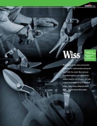
Material <strong>Hand</strong>ling<br />
Products
The Campbell ® Chain story<br />
Campbell can trace its beginnings back to 1834, when one of the many companies that eventually<br />
became what is today the Campbell ® brand began manufacturing harnesses for horses. Over the years,<br />
countless products were added, including wire rope and chain fittings, drop-forged chain hardware,<br />
high quality tackle blocks, shackles, hooks, and much more.<br />
Today, Campbell is the best-selling brand of welded and weldless chain in the United States. Users can<br />
select from a wide range of working load capacities, including proof coil, high test, transport, and alloy.<br />
Many finishes, styles, and materials are also available. Campbell chains and assemblies, including slings<br />
for overhead lifting, tie-downs, and binder chains, have earned the brand an outstanding reputation<br />
for quality.<br />
Innovation is also a key element of the Campbell philosophy. Grade 100 chain was pioneered and<br />
developed by Campbell, resulting in products that featured 25% higher working load limits,<br />
manufactured proof tests, and design strengths than Grade 80 chain products. This kind of<br />
innovation, combined with unparalleled technical support, expertise, and training, provides<br />
Campbell customers with a level of satisfaction<br />
www.apexhandtools.com/<strong>campbell</strong><br />
unrivaled in the industry.
Chain<br />
2<br />
Campbell ® Chain<br />
Founded in 1919, Campbell is the largest manufacturer of welded and weldless<br />
chain in the United States. Users of Campbell chain can select from a wide<br />
range of working load capacities including proof coil, high test, transport and<br />
alloy; finishes including self-colored, Blu-Krome ® , galvanized and bright color<br />
polycoated; links that are short, long, twisted, locked, looped, even stamped<br />
from flat stock. Several chain types are even available in solid brass and bronze.<br />
Campbell chains and assemblies, including slings for overhead lifting, and<br />
binder chains, have earned for the manufacturer an outstanding reputation for<br />
quality.<br />
Contents Page No.<br />
Cable 36 - 37, 39, 41<br />
Camtrol comparison system 3<br />
Chain, aluminum 17<br />
Chain, animal 41 - 42<br />
Chain, ball 34 - 35<br />
Chain, BBB 9<br />
Chain, binder 38 - 39<br />
Chain, cam-alloy 16<br />
Chain, cathedral 33<br />
Chain, clock 34<br />
Chain, coil 20 - 23, 44 - 45<br />
Chain, construction 38<br />
Chain, decorator 32 - 33<br />
Chain, dock fender 15<br />
Chain, fishing 15<br />
Chain, high test 10-11<br />
Chain, hobby/craft 32 - 34<br />
Chain, jack 29 - 30, 46<br />
Chain, log 39<br />
Chain, loop 25, 27 - 28, 45<br />
Chain, machine 18 - 20, 44<br />
Chain, marine 8, 12<br />
Chain, marine alloy 12<br />
Chain, mooring 9<br />
Chain, oval link 35<br />
Chain, passing link 23 - 24, 46<br />
Chain, plastic 35 - 36<br />
Chain, plumber’s 26<br />
Chain, porch swing 43<br />
Chain, proof coil 6 - 8<br />
Chain, sash 30 - 31, 46<br />
ADVERTENCIA<br />
Chain, stainless steel 17<br />
Para Chain, prevenir sweep la posibilidad de una lesión personal sería: 11<br />
• Chain, NO EXCEDA studio los límites de carga de las cadenas o componentes. 22<br />
• NO LA UTILICE para cargar hacia arriba o para izar.<br />
• Chain, NO LA tow UTILICE si la cadena o los componentes están visualmente 40<br />
distorsionados Chain, transporto gastados.<br />
13 - 14<br />
WARNING<br />
chain products<br />
The Campbell operation facilities in York,<br />
PA, and Cortland, NY, conform to Quality<br />
Standard ISO 9001.<br />
Contents Page No.<br />
Chain, tuna 14<br />
Chain, twist 33<br />
Chain, utility 24<br />
Chain, well 29<br />
Chain, winch line 40<br />
Cutters, chain and cable 43<br />
Leads, anchor 8<br />
Sizing chart 44 - 46<br />
Campbell chain numerical index 47 - 48<br />
To prevent the possibility of serious bodily injury:<br />
• DO NOT EXCEED the working load limits for chain or components.<br />
• DO NOT USE for overhead lifting or hoisting.<br />
• DO NOT USE if the chain or components are visibly distorted or<br />
worn.
chain products<br />
Campbell’s CAMTROL SYSTEM makes chain products easier to<br />
identify and understand. That’s because all are based on engineering<br />
formulas computed according to ISO (International Organization for<br />
Standardization), NACM (National Association of Chain Manufacturers)<br />
and ASTM (American Society for Testing and Materials). Use the<br />
CAMTROL SYSTEM to make wise chain purchasing decisions. Use it<br />
to compare the various categories of chain, to choose the right chain<br />
for the job according to the price per thousand pounds of working load<br />
instead of buying on a price per foot.<br />
Consult your Campbell Chain distributor for current prices. Then refer<br />
to the chart below and divide the price per foot by the working load<br />
limit (in thousands of pounds) shown in the table.<br />
By using this comparison system you will discover that you can buy a<br />
smaller, easier to handle chain, and at less cost based on its working<br />
load limit.<br />
Grade<br />
Camtrol<br />
System<br />
Number<br />
ADVERTENCIA<br />
Para prevenir la posibilidad de una lesión personal sería:<br />
• NO EXCEDA los límites de carga de las cadenas o componentes.<br />
• NO LA UTILICE para cargar hacia arriba o para izar.<br />
• NO LA UTILICE si la cadena o los componentes están visualmente<br />
distorsionados o gastados.<br />
www.apexhandtools.com/<strong>campbell</strong><br />
Camtrol System<br />
Variations in finish or heat treatment<br />
The mechanical properties shown on the Camtrol Chart apply only to<br />
the various chains in their standard finish and heat treated condition.<br />
Finishes such as galvanizing or electroplating may reduce strengths.<br />
The manufacturer’s revised recommendations should be solicited<br />
when such treatments are desirable for specific applications.<br />
Hallmarking (Identification)<br />
All System 4, 7, 8, and 10 chains and all System 3 chains 5/16” (8 mm)<br />
and larger are marked with the grade identifier approximately every<br />
12” or less. Please refer to the chain type of interest in this <strong>catalog</strong> for<br />
the specific hallmarks.<br />
Trade Size<br />
Diameter<br />
Nominal Dimensions<br />
Inside Length Inside Width<br />
Weight Per<br />
100 Feet<br />
Working Load<br />
Limit<br />
in. mm in. mm in. mm in. mm lb kg lb kg<br />
30 3 1/8 4 .156 4.0 .89 22.61 .29 7.33 22 10 400 180<br />
30 3 3/16 5.5 .205 5.5 .95 24.13 .34 8.63 35 16 800 365<br />
30 3 1/4 7 .260 7.0 1.20 30.50 .45 11.40 56 25 1,300 580<br />
30 3 5/16 8 .312 8.0 1.27 32.27 .47 11.93 83 38 1,900 860<br />
30 3 3/8 10 .369 10.0 1.36 34.46 .57 14.47 125 57 2,650 1,200<br />
30 3 1/2 13 .480 13.0 1.70 43.18 .75 19.00 237 108 4,500 2,030<br />
30 3 5/8 16 .656 16.7 2.10 53.34 .87 22.09 390 177 6,900 3,130<br />
30 3 3/4 20 .781 19.8 2.70 68.58 1.02 26.00 535 243 10,600 4,810<br />
30 3 7/8 22 .906 23.0 2.34 59.44 1.37 34.80 770 349 12,800 5,810<br />
43 4 1/4 7 .276 7.0 1.20 30.50 .45 11.40 63 28 2,600 1,180<br />
43 4 5/16 8 .330 8.4 1.27 32.27 .47 11.94 102 46 3,900 1,770<br />
43 4 3/8 10 .394 10.0 1.15 29.21 .58 14.73 160 73 5,400 2,450<br />
43 4 7/16 11.9 .468 11.9 1.29 32.77 .67 17.02 216 98 7,200 3,270<br />
43 4 1/2 13 .531 13.0 1.70 43.18 .75 19.00 260 118 9,200 4,170<br />
43 4 5/8 16 .656 16.7 1.94 49.27 .93 23.62 356 161 13,000 5,910<br />
43 4 3/4 20 .781 23.0 2.21 56.13 1.10 27.94 535 243 20,200 9,180<br />
70 7 1/4 7 .312 7.9 .94 23.88 .46 11.68 91 41 3,150 1,430<br />
70 7 5/16 8.7 .343 8.7 1.01 25.65 .48 11.68 111 50 4,700 2,130<br />
70 7 3/8 10 .406 10 1.36 34.46 .57 14.47 150 68 6,600 2,990<br />
70 7 7/16 11.9 .468 11.9 1.29 32.77 .67 17.02 212 96 8,750 3,970<br />
70 7 1/2 13 .531 13.0 1.70 43.18 .75 19.00 260 118 11,300 5,130<br />
70 7 5/8 16 .630 16.0 1.93 49.02 .87 22.10 375 170 15,800 7,170<br />
80 8 7/32 5.5 .218 5.5 .69 17.53 .30 7.62 43 20 2,100 970<br />
80 8 5/16 8 .315 8.0 .94 23.88 .46 11.68 92 42 4,500 2,000<br />
80 8 1 26 1.000 25.4 2.80 71.12 1.40 35.56 965 438 47,700 21,600<br />
80 8 1 1/4 32 1.250 31.8 3.50 88.90 1.75 44.45 1525 692 72,300 32,800<br />
63 6 1 1/2 38 1.500 38.1 4.49 114.04 1.94 49.27 2140 971 80,000 36,400<br />
100 10 9/32 7 .285 7.2 .86 21.80 .41 11.40 74 34 4,300 1,950<br />
100 10 3/8 10 .402 10.2 1.22 31.00 .55 14.00 148 67 8,800 3,990<br />
100 10 1/2 13 .522 13.2 1.54 39.90 .45 19.10 250 113 15,000 6,800<br />
100 10 5/8 16 .643 16.3 1.93 49.00 .87 22.10 379 172 22,600 10,250<br />
100 10 3/4 20 .802 20.4 2.42 61.50 1.09 27.70 598 271 35,300 16,000<br />
100 10 7/8 22 .882 22.4 2.70 68.52 1.28 32.48 775 351 42,700 19,400<br />
WARNING<br />
To prevent the possibility of serious bodily injury:<br />
• DO NOT EXCEED the working load limits for chain or components.<br />
• DO NOT USE for overhead lifting or hoisting.<br />
• DO NOT USE if the chain or components are visibly distorted or<br />
worn.<br />
Chain<br />
3
Chain<br />
4<br />
Important Chain Terms<br />
WORKING LOAD LIMIT<br />
The “working load limit” (rated capacity) is the maximum combined<br />
static and dynamic load in pounds or kilograms that should never be<br />
applied to the product in service, even when the product is new, and<br />
when the load is uniformly applied in direct tension to the product.<br />
Campbell chain products and components are designed and built for<br />
rugged lasting service. As with any quality product certain precautions<br />
and standards of treatment should be observed. Proper care<br />
will extend the useful life of the product.<br />
INSTRUCTIONS REGARDING COMPONENTS AND FITTINGS<br />
Components, such as hooks or shackles, should have at least the<br />
same working load limit (rated capacity) as the chain with which they<br />
are used. If not, the assembly shall be rated to the capacity of the<br />
weakest component. Campbell offers a full line of components engineered<br />
specifically to be compatible with our chain products.<br />
WARNINGS AND CAUTIONS<br />
• The use of chain is subject to certain hazards that cannot be met by<br />
mechanical or manufacturing means, but only by the exercise of<br />
intelligence, care, and common sense<br />
• Do not exceed the working load limit of the chain or any<br />
component<br />
• Chemically active environments may adversely affect chain and<br />
components. Do not use in highly acidic or caustic environments.<br />
Campbell should be contacted if the chain will be exposed to<br />
chemically active environments during use<br />
• High and low temperatures will affect chain and components.<br />
Campbell should be contacted if temperatures below -20°F (-29°C)<br />
or above 400°F (200°C) will be experienced<br />
• Chains used in certain applications are subject to governmental<br />
regulations. Please follow all Federal, State and/or Local Department<br />
of Transportation, OSHA, or other applicable standards and<br />
regulations when using Campbell products<br />
• Never field weld or repair chain<br />
• See other specific information under “Inspection and Proper Use”<br />
sections<br />
INSPECTION<br />
Regular inspections should be conducted on chain to detect damage<br />
or deterioration from use. The chain should be inspected for any<br />
of the below conditions. If present, the chain should immediately be<br />
removed from service.<br />
• Cracks in the chain or any component<br />
• Excessive nicks or gouges<br />
• Excessive wear. Chain should be removed from service if the<br />
thickness at any point on the link is below the value shown in the<br />
Chain Minimum Allowable Thickness chart. All other components<br />
should be removed from service if any dimension is worn by more<br />
than 10% from the original dimension<br />
• Stretched, bent, twisted, or distorted chain links or components<br />
• Excessive corrosion<br />
• Evidence of heat damage<br />
• Evidence of field welding or weld splatter<br />
• Any other condition which questions the integrity of the chain<br />
ADVERTENCIA<br />
Para prevenir la posibilidad de una lesión personal sería:<br />
PROPER USE • NO EXCEDA los límites de carga de las cadenas o componentes.<br />
To protect the users and to prevent damage to the chain, the follow-<br />
• NO LA UTILICE para cargar hacia arriba o para izar.<br />
ing • NO<br />
safe<br />
LA<br />
practices<br />
UTILICE<br />
should<br />
si la cadena<br />
be followed:<br />
o los componentes están visualmente<br />
• Select<br />
distorsionados<br />
a chain suitable<br />
o gastados.<br />
for the application and environment<br />
WARNING<br />
chain products<br />
chain products<br />
PROOF TEST<br />
The “proof test” is a quality control test applied to chain for the purpose<br />
of verifying weld and material quality. It is the minimum force<br />
in pounds or newtons that the chain has withstood in direct tension<br />
as part of the manufacturing process. Proof testing assures that the<br />
chain is more than capable of performing at its rated working load<br />
limit. Proof test loads are a manufacturing integrity test and shall not<br />
be used as criteria for service or design purposes. All Campbell proof<br />
tested chain and components are proof tested in accordance with the<br />
applicable ASTM, NACM and AISI/ASME requirements.<br />
Warnings, Cautions, Inspection and Proper Use of Chain<br />
• The hooks or other components should be of a size to fit the<br />
intended connections<br />
• Avoid shock loading<br />
• Pad all sharp edges or corners in contact with the chain<br />
• Rig so that the load is properly seated in the hooks or other<br />
components. Avoid tip loading of hooks and side loadingof chain<br />
and components<br />
• Avoid twisting or kinking the chain<br />
• Never knot chain<br />
Purchasers please note that all “Warnings and Cautions” apply to<br />
chain as well as all components and fittings. Purchasers are responsible<br />
for conveying the “Warnings and Cautions,” including the<br />
“Inspection” and “Proper Use” section information to the end user.<br />
Campbell denies any liability for damage that results from use in excess<br />
of the working load limit or any abuse or misuse of the product.<br />
Any questions concerning the use of Campbell products may be directed<br />
to your Apex Tool Group Sales representative or Apex Tool Group<br />
Customer Service representative.<br />
OTHER PRODUCTS<br />
Campbell produces a number of products for specialty applications.<br />
Please contact your Apex Tool Group Sales representative, or<br />
Customer Service representative, if you have special requirements.<br />
Not all products produced by Campbell appear in this <strong>catalog</strong>.<br />
Campbell can produce engineered chain to meet customer design<br />
specifications, and also produces a variety of chain assemblies.<br />
Minimum order quantities may apply to special order products.<br />
NOTICE: The product specifications and dimensions are as accurate<br />
as possible at the time of printing. However, because we are continually<br />
improving the quality and design of our products, they can<br />
change without notice.<br />
The dimensions and weights are approximate nominal values, and<br />
some variation will occur. If specific dimensional requirements are<br />
necessary for the application, please contact your Apex Tool Group<br />
Sales representative, or Customer Service representative.<br />
To prevent the possibility of serious bodily injury:<br />
• DO NOT EXCEED the working load limits for chain or components.<br />
• DO NOT USE for overhead lifting or hoisting.<br />
• DO NOT USE if the chain or components are visibly distorted or<br />
worn.
chain products<br />
• (S.C.) stands for Self Colored. A finish without any cleaning<br />
operations to remove oil or dirt or surface oxidation from the<br />
welding process<br />
• (BRT) stands for Bright. A finish where the surface is cleaned by<br />
shot peening or tumbling to produce a clean bright surface<br />
• (Z.P.) stands for Zinc Plated, Campbell’s method of zinc electroplating.<br />
The zinc electroplating is an attractive finish that<br />
also serves to prevent the onset of rust on the chain.<br />
• (Y.C.) stands for Yellow Chromate, a name for Campbell’s method<br />
of zinc electroplating with a yellow chromate finish. The zinc<br />
electroplating is an attractive finish that also serves to prevent the<br />
onset of rust on the chain. The chromate finish serves to protect<br />
the zinc electroplate<br />
• (GALV) stands for Hot-dip Galvanized. Hot-dip galvanizing is a<br />
process where the chain is immersed in molton zinc. This<br />
produces both a chemical reaction between the steel and the zinc,<br />
ADVERTENCIA<br />
Para prevenir la posibilidad de una lesión personal sería:<br />
• NO EXCEDA los límites de carga de las cadenas o componentes.<br />
• NO LA UTILICE para cargar hacia arriba o para izar.<br />
• NO LA UTILICE si la cadena o los componentes están visualmente<br />
distorsionados o gastados.<br />
www.apexhandtools.com/<strong>campbell</strong><br />
Care and Maintenance of Chain<br />
Minimum Allowable Thickness Chart<br />
Nominal Min. Allowable<br />
Trade Size Chain Type Material Diamter Thickness on Link<br />
in. mm or Grade in. mm in. mm<br />
4 3.0 Machine, Coil 0.120 3.0 0.104 2.64<br />
3 3.4 Machine, Coil 0.135 3.4 0.117 2.97<br />
2 3.8 Machine, Coil 0.148 3.8 0.128 3.25<br />
1 4.1 Machine, Coil 0.162 4.1 0.140 3.56<br />
1/0 4.5 Machine, Coil 0.177 4.5 0.153 3.89<br />
2/0 4.9 Machine, Coil, Passing Link 0.192 4.9 0.166 4.22<br />
3/0 5.3 Machine, Coil 0.207 5.3 0.179 4.55<br />
4/0 5.5 Machine, Coil, Passing Link 0.218 5.5 0.189 4.80<br />
5/0 6.4 Machine, Coil 0.250 6.4 0.217 5.50<br />
1/8 4.0 Grade 30 0.156 4.0 0.135 3.43<br />
3/16 5.5 Grade 30, 80, 100 0.217 5.5 0.189 4.80<br />
1/4-9/32 7.0 Grade 30, 43, 70, 80, 100 (Grade 43 = 0.281) 0.276 7.0 0.239 6.07<br />
5/16 8.4 Grade 30 0.331 8.4 0.286 7.28<br />
5/16 8.7 Grade 43, 70 0.343 8.7 0.297 7.54<br />
5/16 8.0 Grade 80, 100 0.312 8.0 0.273 6.93<br />
3/8 10.0 Grade 30, 80, 100 0.394 10.0 0.342 8.69<br />
3/8 10.3 Grade 43, 70 0.406 10.3 0.351 8.93<br />
7/16 11.9 Grade 30, 43, 70 0.468 11.9 0.405 10.30<br />
1/2 13.0 Grade 30, 80, 100 0.512 13.0 0.443 11.26<br />
1/2 13.5 Grade 43, 70 0.531 13.5 0.460 11.68<br />
5/8 16.0 Grade 30, 43, 70 0.630 16.0 0.546 13.87<br />
3/4 20.0 Grade 80, 100 0.787 20.0 0.687 17.45<br />
7/8 20.0 Grade 30, 43, 80, 100 0.866 22.0 0.750 19.05<br />
1 26.0 Grade 30, 80 1.020 26.0 0.887 22.53<br />
1-1/4 32.0 Grade 80 1.260 32.0 1.091 27.71<br />
1-1/2 38.0 Grade 63 1.500 38.0 1.300 32.99<br />
Warning: Remove chain from service if the thickness is less than the minimum shown, at any location on the link<br />
Finish Abbreviations<br />
as well as an outside layer of zinc on the chain. The end result is<br />
an adherent coating of zinc that is much thicker than that produced<br />
by zinc electroplating. Corrosion resistance is proportional to zinc<br />
thickness, and therefore galvanized products offer superior corrosion<br />
resistance to electroplated products.<br />
Note: Due to the temperature of the molten zinc, the strengths of<br />
hot-dip galvanized products are often reduced by 15%<br />
• (M-GALV) stands for Mechanically Galvanized. Mechanical galvanizing<br />
is a process where zinc powder is mechanically applied to the<br />
outside of the chain. Because this is a mechanical process and not a<br />
molten process, the coating is very uniform<br />
• (Polycoated) is a finish where the chain is coated with a colored<br />
plastic powder which is then fused onto each link<br />
WARNING<br />
To prevent the possibility of serious bodily injury:<br />
• DO NOT EXCEED the working load limits for chain or components.<br />
• DO NOT USE for overhead lifting or hoisting.<br />
• DO NOT USE if the chain or components are visibly distorted or<br />
worn.<br />
Chain<br />
5
Chain<br />
6<br />
System 3, Proof Coil Chain (Grade 30)<br />
• Uses: Excellent general-purpose chain of standard<br />
commercial quality<br />
• Frequently used for fabricating tow chains, binding or<br />
tie down chains and logging chains<br />
• Standard Material: Low carbon steel<br />
• Standard Finish: Self Colored (S.C.) or Galvanized<br />
(GALV); also available Zinc Plated (Z.P.) 3/16” through<br />
1/2”; and polycoated<br />
ADVERTENCIA<br />
Para prevenir la posibilidad de una lesión personal sería:<br />
• NO EXCEDA los límites de carga de las cadenas o componentes.<br />
• NO LA UTILICE para cargar hacia arriba o para izar.<br />
• NO LA UTILICE si la cadena o los componentes están visualmente<br />
distorsionados o gastados.<br />
WARNING<br />
chain products<br />
Drums Half Drums Round Pails SquarePails Reels<br />
• Hallmarking: “C3” or “M3” on 5/16” (8mm) and larger<br />
• Proof tested<br />
• Packaging: Drums and half drums (order unit is<br />
“feet”), pails and refill reels to fit Campbell merchandisers<br />
(order unit is “each”)<br />
• Do not use for overhead lifting<br />
Drums, System 3, Proof Coil Chain (Order Unit is “Feet”)<br />
Nominal Dimensions (in. and mm)<br />
Trade<br />
Size<br />
in. mm<br />
Mat.<br />
Dia.<br />
in. mm<br />
Inside Dimensions<br />
Length Width<br />
in. mm in. mm<br />
Self Colored<br />
Cat. UPC No.<br />
No. 020418<br />
Zinc Plated<br />
Cat. UPC No.<br />
No. 020418<br />
Galvanized<br />
Cat. UPC No.<br />
No. 020418<br />
Working<br />
Load Limit<br />
lb kg<br />
Length/<br />
ft. per<br />
drum<br />
Lb/<br />
100’<br />
Links/<br />
ft.<br />
1<br />
⁄8 4 .16 4 .89 23 .29 7 0120202 056932 -- -- 0120232 056949 400 180 1000 19 13.5<br />
3 ⁄16 6 .21 6 .95 24 .34 9 0120302 056970 0120322 057007 0120332 057045 800 365 1000 35 12.6<br />
1 ⁄4 7 .26 7 1.20 30 .45 11 0120402 057076 0120422 057106 0120432 057144 1300 580 800 56 10.0<br />
5 ⁄16 8 .31 8 1.27 32 .47 12 0120502 057205 0120522 057243 0120532 057281 1900 860 550 83 9.4<br />
3 ⁄8 10 .37 10 1.36 35 .57 14 0120602 057335 0120622 057373 0120632 057410 2650 1200 400 125 8.8<br />
7 ⁄16 12 .47 12 1.37 35 .75 19 -- -- -- -- 0120732 057489 3700 1680 300 210 8.8<br />
1 ⁄2 13 .48 13 1.70 43 .75 19 0120802 057502 0120822 057526 0120832 057557 4500 2030 200 238 7.1<br />
5 ⁄8 16 .66 17 2.10 53 .87 22 0121002 057595 -- -- 0121032 057618 6900 3130 150 390 5.7<br />
3 ⁄4 20 .78 20 2.70 69 1.02 26 0121202 057632 -- -- 0121232 057656 10,600 4800 100 536 4.4<br />
Half Drums, System 3, Proof Coil Chain (Order Unit is “Feet”)<br />
Nominal Dimensions (in. and mm)<br />
Trade<br />
Size<br />
in. mm<br />
Mat.<br />
Dia.<br />
in. mm<br />
Inside Dimensions<br />
Length Width<br />
in. mm in. mm<br />
Self Colored<br />
Cat. UPC No.<br />
No. 020418<br />
Zinc Plated<br />
Cat. UPC No.<br />
No. 020418<br />
Galvanized<br />
Cat. UPC No.<br />
No. 020418<br />
Working<br />
Load Limit<br />
lb kg<br />
Length/<br />
ft. per<br />
drum<br />
Lb/<br />
100’<br />
Links/<br />
ft.<br />
3<br />
⁄16 6 .21 6 .95 24 .34 9 0120300 056956 -- -- 0120330 057021 800 365 500 35 12.6<br />
1 ⁄4 7 .26 7 1.20 30 .45 11 0120400 057052 -- -- 0120430 057120 1300 580 400 56 10.0<br />
5 ⁄16 8 .31 8 1.27 32 .47 12 0120500 057182 -- -- 0120530 057267 1900 860 275 83 9.4<br />
3 ⁄8 10 .37 10 1.36 35 .57 14 0120600 057311 -- -- 0120630 057397 2650 1200 200 125 8.8<br />
To prevent the possibility of serious bodily injury:<br />
• DO NOT EXCEED the working load limits for chain or components.<br />
• DO NOT USE for overhead lifting or hoisting.<br />
• DO NOT USE if the chain or components are visibly distorted or<br />
worn.
chain products<br />
ADVERTENCIA<br />
Para prevenir la posibilidad de una lesión personal sería:<br />
• NO EXCEDA los límites de carga de las cadenas o componentes.<br />
• NO LA UTILICE para cargar hacia arriba o para izar.<br />
• NO LA UTILICE si la cadena o los componentes están visualmente<br />
distorsionados o gastados.<br />
www.apexhandtools.com/<strong>campbell</strong><br />
Nominal Dimensions (in. and mm)<br />
Trade Mat. Inside Dimensions Self Colored Zinc Plated Galvanized Working<br />
Size Dia. Length Width Cat. UPC No. Cat. UPC No. Cat. UPC No. Load Limit Ft. per Lb/ Links/<br />
in. mm in. mm in. mm in. mm No. 020418 No. 020418 No. 020418 lb kg pail ‡ pail ft.<br />
3<br />
⁄16 6 .21 6 .95 24 .34 9 -- -- 0140323 057991 0140333 058004 800 365 250 88 12.6<br />
1 ⁄4 7 .26 7 1.20 30 .45 11 0120402 057076 0120422 057106 0120432 057144 1300 580 800 56 10.0<br />
5 ⁄16 8 .31 8 1.27 32 .47 12 0120502 057205 0120522 057243 0120532 057281 1900 860 550 83 9.4<br />
3 ⁄8 10 .37 10 1.36 35 .57 14 0120602 057335 0120622 057373 0120632 057410 2650 1200 400 125 8.8<br />
7 ⁄16 12 .47 12 1.37 35 .75 19 -- -- -- -- 0120732 057489 3700 1680 300 210 8.8<br />
1 ⁄2 13 .48 13 1.70 43 .75 19 0120802 057502 0120822 057526 0120832 057557 4500 2030 200 238 7.1<br />
5 ⁄8 16 .66 17 2.10 53 .87 22 0121002 057595 -- -- 0121032 057618 6900 3130 150 390 5.7<br />
3 ⁄4 20 .78 20 2.70 69 1.02 26 0121202 057632 -- -- 0121232 057656 10,600 4800 100 536 4.4<br />
‡ Approximate.<br />
Nominal Dimensions (in. and mm)<br />
Trade Mat. Inside Dimensions Zinc Plated Galvanized Working<br />
Size Dia. Length Width Cat. UPC No. Cat. UPC No. Load Limit Ft. per Lb/ Links/<br />
in. mm in. mm in. mm in. mm No. 020418 No. 020418 lb kg pail ‡ pail ft.<br />
1<br />
⁄8 4 .16 4 .89 23 .29 7 0143226 190360 -- -- 400 180 200 38 13.5<br />
1 ⁄8 4 .16 4 .89 23 .29 7 -- -- 0143236 189326 400 180 325 62 13.5<br />
3 ⁄16 6 .21 6 .95 24 .34 9 0143326 183058 0143336 183065 800 365 150 53 12.6<br />
1 ⁄4 7 .26 7 1.20 30 .45 11 0143426 183072 0143436 183089 1300 580 100 56 10.0<br />
5 ⁄16 8 .31 8 1.27 32 .47 12 0143526 183096 0143536 183102 1900 860 75 62 9.4<br />
3 ⁄8 10 .37 10 1.36 35 .57 14 0143626 183119 0143636 183126 2650 1200 45 56 8.8<br />
‡ Approximate.<br />
Nominal Dimensions (in. and mm)<br />
Trade Mat. Inside Dimensions Polycoated** Working<br />
Size Dia. Length Width Cat.<br />
UPC No.<br />
Load Limit Ft. per Lb/ Links/<br />
in. mm in. mm in. mm in. mm No.<br />
020418<br />
lb kg pail ‡ pail ft.<br />
5<br />
⁄16 8 .31 8 1.27 32 .47 12 HV0142526 187940 1900 860 75 62 9.4<br />
** Hi-visibility orange polycoated. ‡ Approximate.<br />
Round Pails, System 3, Proof Coil Chain<br />
(Order Unit is “Each Pail”)<br />
Square Pails, System 3, Proof Coil Chain<br />
(Order Unit is “Each Pail”)<br />
Square Pails, System 3, Proof Coil Chain<br />
(Order Unit is “Each Pail”)<br />
WARNING<br />
To prevent the possibility of serious bodily injury:<br />
• DO NOT EXCEED the working load limits for chain or components.<br />
• DO NOT USE for overhead lifting or hoisting.<br />
• DO NOT USE if the chain or components are visibly distorted or<br />
worn.<br />
Chain<br />
7
Chain<br />
8<br />
ADVERTENCIA<br />
Para prevenir la posibilidad de una lesión personal sería:<br />
• NO EXCEDA los límites de carga de las cadenas o componentes.<br />
• NO LA UTILICE para cargar hacia arriba o para izar.<br />
• NO LA UTILICE si la cadena o los componentes están visualmente<br />
distorsionados o gastados.<br />
WARNING<br />
chain products<br />
Square Pails, Anchor lead, System 3, Proof Coil Chain<br />
(Order Unit is “Each Pail”)<br />
Nominal Dimensions (in. and mm)<br />
Trade Mat. Inside Dimensions Galvanized & PolyCoated** Working<br />
Size Dia. Length Width Cat.<br />
UPC No.<br />
Load Limit Ft. per Lb/ Links/<br />
in. mm in. mm in. mm in. mm No.<br />
020418<br />
lb kg pail ‡ pail ft.<br />
5<br />
⁄16 8 .31 8 1.27 32 .47 12 0200356 183881 1900 860 75 62 9.4<br />
** White polycoated. ‡ Approximate.<br />
Reels, System 3, Proof Coil Chain (Order Unit is “Each Reel”)<br />
Nominal Dimensions (in. and mm)<br />
Trade<br />
Size<br />
in. mm<br />
Mat.<br />
Dia.<br />
in. mm<br />
Inside Dimensions<br />
Length Width<br />
in. mm in. mm<br />
Zinc Plated<br />
Cat. UPC No.<br />
No. 020418<br />
Polycoated Yellow<br />
Cat. UPC No.<br />
No. 020418<br />
Working<br />
Load Limit<br />
lb kg<br />
Feet/<br />
Reel<br />
Lb/<br />
Reel<br />
Reel<br />
Width<br />
in.<br />
3<br />
⁄16 6 .21 6 .95 24 .34 9 0725027 064982 PD0725027 184642 800 365 100 35 10.75<br />
1 ⁄4 7 .26 7 1.20 30 .45 11 0722127 183270 -- -- 1300 580 65 36 10.75<br />
1 ⁄4 7 .26 7 1.20 30 .45 11 -- -- PD0722127 183393 1300 580 60 36 10.75<br />
5 ⁄16 8 .31 8 1.27 32 .47 12 0722227 183287 -- -- 1900 860 60 50 10.75<br />
3 ⁄8 10 .37 10 1.36 35 .57 14 0722327 183294 -- -- 2650 1200 35 44 10.75<br />
Drums, Marine, Proof Coil Chain (Order Unit is “Feet”)<br />
Drums<br />
• An excellent low-carbon steel chain made with a<br />
shorter link length than standard proof coil<br />
• Packaging: Drums (order unit is “feet”)<br />
• Standard finish: Hot Dipped Galvanized (GALV)<br />
• Proof tested<br />
Nominal Dimensions (in. and mm)<br />
Trade Mat. Inside Dimensions Working<br />
Size Dia. Length Width Cat.<br />
UPC No. Load Limit<br />
in. mm in. mm in. mm in. mm No.<br />
020418 lb kg<br />
Hot Dipped Galvanized<br />
1 ⁄4 7 .28 7 1.00 25 .50 13 0128132 170645 1300 590 800 73 12<br />
5 ⁄16 8 .34 9 1.10 28 .50 13 0128232 170652 1900 862 550 102 11<br />
3 ⁄8 10 .41 10 1.23 31 .62 16 0128332 170669 2650 1202 400 160 9.7<br />
1 ⁄2 13 .53 13 1.50 38 .81 21 0128432 170676 4500 2041 200 277 7.8<br />
Self-colored<br />
1 ⁄4 7 .28 7 1.00 25 .50 13 0128102∆ 182969 1300 590 800 73 12<br />
5 ⁄16 8 .34 9 1.10 28 .50 13 0128202∆ 182976 1900 862 550 102 11<br />
3 ⁄8 10 .41 10 1.23 31 .62 16 0128302∆ 182983 2650 1202 400 160 9.7<br />
∆ These items are made to order.<br />
Feet/<br />
Drum<br />
Lb/<br />
100’<br />
Links/<br />
foot<br />
To prevent the possibility of serious bodily injury:<br />
• DO NOT EXCEED the working load limits for chain or components.<br />
• DO NOT USE for overhead lifting or hoisting.<br />
• DO NOT USE if the chain or components are visibly distorted or<br />
worn.
chain products<br />
ADVERTENCIA<br />
Para prevenir la posibilidad de una lesión personal sería:<br />
• NO EXCEDA los límites de carga de las cadenas o componentes.<br />
• NO LA UTILICE para cargar hacia arriba o para izar.<br />
• NO LA UTILICE si la cadena o los componentes están visualmente<br />
distorsionados o gastados.<br />
www.apexhandtools.com/<strong>campbell</strong><br />
Drums, Mooring Chain (Order Unit is “Feet”)<br />
• An excellent low-carbon steel chain with a long<br />
link design for mooring applications<br />
• The longer link allows the use of a shackle anywhere<br />
in the length of chain, not just at end links<br />
• Greater Working Load Limit than Proof Coil<br />
• Standard finish: Hot Dipped Galvanized (GALV)<br />
• Packaging: Drums (order unit is “feet”)<br />
• Proof tested<br />
• Made especially for windlass or pocket wheel<br />
applications, low carbon steel<br />
• Packaged in drums, Order unit is “feet”<br />
• Standard finish: Self-colored (S.C.)<br />
• Proof tested<br />
Drums<br />
Nominal Dimensions (in. and mm)<br />
Trade Mat. Inside Dimensions Hot Dipped Galvanized Working<br />
Size Dia. Length Width Cat.<br />
UPC No. Load Limit Feet/ Lb/ Links/<br />
in. mm in. mm in. mm in. mm No.<br />
020418 lb kg Drum 100’ foot<br />
3<br />
⁄8 10 .41 10 1.23 31 .62 16 0128332 170669 2650 1202 400 160 9.7<br />
1 ⁄2 13 .53 13 1.50 38 .81 21 0128432 170676 4500 2041 200 277 7.8<br />
5 ⁄8 16 .63 16 2.52 64 .94 24 0129532 152078 9000 4082 150 340 --<br />
3 ⁄4 20 .79 20 3.00 76 1.16 29 0129632 152085 13500 6123 100 510 --<br />
Drums, BBB Chain (Order Unit is “Feet”)<br />
Nominal Dimensions (in. and mm)<br />
Trade Mat. Inside Dimensions Working<br />
Size Dia. Length Width Cat.<br />
UPC No.<br />
Load Limit Ft. per Lb/ Links/<br />
in. mm in. mm in. mm in. mm No.<br />
020418<br />
lb kg pail ‡ pail ft.<br />
Self-colored<br />
9<br />
⁄16 14 .59 15 1.58 40 .78 20 0150902 058493 5875 2665 200 350 7<br />
WARNING<br />
To prevent the possibility of serious bodily injury:<br />
• DO NOT EXCEED the working load limits for chain or components.<br />
• DO NOT USE for overhead lifting or hoisting.<br />
• DO NOT USE if the chain or components are visibly distorted or<br />
worn.<br />
Chain<br />
9
Chain<br />
10<br />
System 4, High Test Chain (Grade 43)<br />
• Uses: Designed for use in load binding, towing,<br />
logging and other applications requiring high strength<br />
• Standard Material: Carbon steel<br />
• Standard Finish: Bright (BRT) and Galvanized(GALV);<br />
Zinc Plated (Z.P.) available in drums, pails and reels<br />
• Hallmarking: “C4” or “M4”<br />
ADVERTENCIA<br />
Para prevenir la posibilidad de una lesión personal sería:<br />
• NO EXCEDA los límites de carga de las cadenas o componentes.<br />
• NO LA UTILICE para cargar hacia arriba o para izar.<br />
• NO LA UTILICE si la cadena o los componentes están visualmente<br />
distorsionados o gastados.<br />
WARNING<br />
chain products<br />
Drums Round Pails Square Pails<br />
• Proof tested<br />
• Packaging: Drums (order unit is “feet”), pails and<br />
refill reels to fit Campbell merchandisers (order unit<br />
is “each”)<br />
• Do not use for overhead lifting<br />
Drums, System 4, High Test Chain (Order Unit is “Feet”)<br />
Nominal Dimensions (in. and mm)<br />
Trade<br />
Size<br />
in. mm<br />
Mat.<br />
Dia.<br />
in. mm<br />
Inside Dimensions<br />
Length Width<br />
in. mm in. mm<br />
Bright<br />
Cat. UPC No.<br />
No. 020418<br />
Zinc Plated<br />
Cat. UPC No.<br />
No. 020418<br />
Galvanized<br />
Cat. UPC No.<br />
No. 020418<br />
Working<br />
Load Limit<br />
lb kg<br />
Feet/<br />
Drum Lb/<br />
100’<br />
Links/<br />
ft.<br />
1<br />
⁄4 7 .28 7 1.20 30 .45 11 0180412 058769 0180422 058790 0180432 058820 2600 1180 800 63 10.0<br />
5 ⁄16 8 .33 8 1.27 32 .47 12 0180512 058851 0180522 058882 0180532 058912 3900 1770 550 95 9.4<br />
3 ⁄8 10 .39 10 1.15 29 .58 15 0180612 058943 -- -- 0180632 059018 5400 2450 400 155 10.4<br />
1 ⁄2 13 .53 13 1.70 43 .75 19 0180812 059094 -- -- 0180832 059155 9200 4170 200 260 7.1<br />
5 ⁄8 16 .66 17 1.94 49 .93 24 0181012 059186 -- -- 0181032 059216 13,000 5910 150 356 6.2<br />
3 ⁄4 20 .78 20 2.21 56 1.10 28 0181212 059254 -- -- -- -- 20,200 9180 100 581 5.4<br />
Round, Pails, System 4, High Test Chain<br />
(Order Unit is “Each Pail”)<br />
Nominal Dimensions (in. and mm)<br />
Trade<br />
Size<br />
in. mm<br />
Mat.<br />
Dia.<br />
in. mm<br />
Inside Dimensions<br />
Length Width<br />
in. mm in. mm<br />
Cat.<br />
No.<br />
Bright<br />
UPC No.<br />
020418<br />
Zinc Plated<br />
Cat. UPC No.<br />
No. 020418<br />
Working<br />
Load Limit<br />
lb kg<br />
Feet/<br />
Pail ‡<br />
Lb/<br />
Pail<br />
Links/<br />
ft.<br />
1<br />
⁄4 7 .28 7 1.20 30 .45 11 0180413 059278 0180423 059285 2600 1180 150 98 10.0<br />
5 ⁄16 8 .33 8 1.27 32 .47 12 0180513 059292 0180523 059308 3900 1770 100 95 9.4<br />
3 ⁄8 10 .39 10 1.15 29 .58 15 0180613 059315 0180623 059322 5400 2450 75 116 10.4<br />
‡ Approximate.<br />
To prevent the possibility of serious bodily injury:<br />
• DO NOT EXCEED the working load limits for chain or components.<br />
• DO NOT USE for overhead lifting or hoisting.<br />
• DO NOT USE if the chain or components are visibly distorted or<br />
worn.
chain products<br />
ADVERTENCIA<br />
Para prevenir la posibilidad de una lesión personal sería:<br />
• NO EXCEDA los límites de carga de las cadenas o componentes.<br />
• NO LA UTILICE para cargar hacia arriba o para izar.<br />
• NO LA UTILICE si la cadena o los componentes están visualmente<br />
distorsionados o gastados.<br />
www.apexhandtools.com/<strong>campbell</strong><br />
Square, Pails, System 4, High Test Chain<br />
(Order Unit is “Each Pail”)<br />
Nominal Dimensions (in. and mm)<br />
Trade<br />
Size<br />
in. mm<br />
Mat.<br />
Dia.<br />
in. mm<br />
Inside Dimensions<br />
Length Width<br />
in. mm in. mm<br />
Cat.<br />
No.<br />
Bright<br />
UPC No.<br />
020418<br />
Galvanized<br />
Cat. UPC No.<br />
No. 020418<br />
Working<br />
Load Limit<br />
lb kg<br />
Feet/<br />
Pail ‡<br />
Lb/<br />
Pail<br />
Links/<br />
ft.<br />
1<br />
⁄4 7 .28 7 1.20 30 .45 11 0184416 183133 0184436 185861 2600 1180 100 66 10.0<br />
5 ⁄16 8 .33 8 1.27 32 .47 12 0184516 183140 0184536 185878 3900 1770 60 57 9.4<br />
3 ⁄8 10 .39 10 1.15 29 .58 15 0184616 183157 0184636 185885 5400 2450 40 63 10.4<br />
‡ Approximate.<br />
Square, Pails, System 4, High Test Chain<br />
(Order Unit is “Each Pail”)<br />
Nominal Dimensions (in. and mm)<br />
Trade Mat. Inside Dimensions Polycoated Hi-Visibility Orange Working<br />
Size Dia. Length Width Cat.<br />
UPC No.<br />
Load Limit Ft. per Lb/ Links/<br />
in. mm in. mm in. mm in. mm No.<br />
020418<br />
lb kg pail ‡ pail ft.<br />
5<br />
⁄16 8 .33 8 1.27 32 .47 12 HV0184526 187698 3900 1770 60 50 9.4<br />
‡ Approximate.<br />
Drums, Sweep Chain (Order Unit is “Feet”)<br />
• Produced specifically for scallop and oyster dredging<br />
• Thru hardened for wear resistance<br />
• Packaged in drums, Order unit is “feet”<br />
• Proof tested<br />
Drums<br />
Nominal Dimensions (in. and mm)<br />
Trade Mat. Inside Dimensions Bright Working<br />
Size Dia. Length Width Cat.<br />
UPC No.<br />
Load Limit Feet/ Lb/ Links/<br />
in. mm in. mm in. mm in. mm No.<br />
020418<br />
lb kg Drum 100’ ft.<br />
5<br />
⁄16 16 .66 16 1.94 49 .93 24 0181092 179921 15800 7170 150 409 6.19<br />
WARNING<br />
To prevent the possibility of serious bodily injury:<br />
• DO NOT EXCEED the working load limits for chain or components.<br />
• DO NOT USE for overhead lifting or hoisting.<br />
• DO NOT USE if the chain or components are visibly distorted or<br />
worn.<br />
Chain<br />
11
Chain<br />
12<br />
ADVERTENCIA<br />
Para prevenir la posibilidad de una lesión personal sería:<br />
• NO EXCEDA los límites de carga de las cadenas o componentes.<br />
• NO LA UTILICE para cargar hacia arriba o para izar.<br />
• NO LA UTILICE si la cadena o los componentes están visualmente<br />
distorsionados o gastados.<br />
WARNING<br />
chain products<br />
Drums, Marine Alloy Trawl Chain (Order Unit is “Feet”)<br />
Midlink<br />
Long Link<br />
• Made of high strength, heat treated alloy steel<br />
• Designed for use with the larger nets in the trawling industry<br />
• Grade 80 strengths<br />
• Proof tested<br />
• Special heat treatment for the trawling industry<br />
• Packaged in drums, Order unit is “feet”<br />
Drums<br />
Nominal Dimensions (in. and mm)<br />
Trade<br />
Inside Dimensions Bright Working<br />
Size<br />
Length Width Cat.<br />
UPC No.<br />
Load Limit Feet/ Lb/ Links/<br />
in. mm in. mm in. mm No.<br />
020418<br />
lb kg Drum 100’ ft.<br />
1<br />
⁄2 13 Long Link 3.15 80 .97 24 0407512 190452 12000 5443 300 190 --<br />
5 ⁄8 16 Long Link 3.71 94 1.00 25 0407612 ∆ 190469 18100 8210 150 315 --<br />
3 ⁄4 19 Long Link 3.99 101 1.29 33 0407712 190476 28300 12837 100 480 --<br />
7 ⁄8 22 Midlink 4.00 102 1.15 29 0406812 ∆ 190445 34200 15513 80 650 --<br />
∆ These items are made to order.<br />
To prevent the possibility of serious bodily injury:<br />
• DO NOT EXCEED the working load limits for chain or components.<br />
• DO NOT USE for overhead lifting or hoisting.<br />
• DO NOT USE if the chain or components are visibly distorted or<br />
worn.
chain products<br />
Drums Half Drums Round Pails SquarePails<br />
• Uses: For use in load binding, towing and logging<br />
• Can be used in accordance with Department of<br />
Transportation regulations<br />
• Standard Material: Heat treated carbon steel<br />
• Standard Finish: Zinc electroplate with yellow<br />
chromate conversion coating<br />
ADVERTENCIA<br />
Para prevenir la posibilidad de una lesión personal sería:<br />
• NO EXCEDA los límites de carga de las cadenas o componentes.<br />
• NO LA UTILICE para cargar hacia arriba o para izar.<br />
• NO LA UTILICE si la cadena o los componentes están visualmente<br />
distorsionados o gastados.<br />
www.apexhandtools.com/<strong>campbell</strong><br />
System 7, Transport Chain (Grade 70)<br />
• Hallmarking: “C7” or “M7”<br />
• Proof tested<br />
• Packaging: Drums and half drums (order unit is<br />
“feet”), pails (order unit is “each”)<br />
• Do not use for overhead lifting<br />
Drums, System 7, Transport Chain (Order Unit is “Feet”)<br />
Nominal Dimensions (in. and mm)<br />
Trade Mat. Inside Dimensions Working<br />
Size Dia. Length Width Cat.<br />
UPC No. Load Limit Feet/ Lb/ Links/<br />
in. mm in. mm in. mm in. mm No.<br />
020418 lb kg Drum 100’ foot<br />
1<br />
⁄4 7 .31 8 .94 24 .46 12 0510412 063763 3150 1430 800 94 12.8<br />
5 ⁄16 8 .34 9 1.01 26 .48 12 0510512 063800 4700 2130 550 111 11.9<br />
3 ⁄8 10 .41 10 1.36 35 .57 14 0510612 063848 6600 2990 400 150 8.8<br />
7 ⁄16 12 .47 12 1.29 33 .67 17 0510712 063886 8750 3970 300 212 9.3<br />
1 ⁄2 13 .53 13 1.70 43 .75 19 0510812 063916 11300 5130 200 260 7.1<br />
Half Drums, System 7, Transport Chain (Order Unit is “Feet”)<br />
Nominal Dimensions (in. and mm)<br />
Trade Mat. Inside Dimensions Working<br />
Size Dia. Length Width Cat.<br />
UPC No. Load Limit Feet/ Lb/ Links/<br />
in. mm in. mm in. mm in. mm No.<br />
020418 lb kg Drum 100’ foot<br />
1<br />
⁄4 7 .31 8 .94 24 .46 12 0510410 063749 3150 1430 400 94 12.8<br />
5 ⁄16 8 .34 9 1.01 26 .48 12 0510510 063787 4700 2130 275 111 11.9<br />
3 ⁄8 10 .41 10 1.36 35 .57 14 0510610 063824 6600 2990 200 150 8.8<br />
1 ⁄2 13 .53 13 1.70 43 .75 19 0510810 063893 11300 5130 100 260 7.1<br />
WARNING<br />
To prevent the possibility of serious bodily injury:<br />
• DO NOT EXCEED the working load limits for chain or components.<br />
• DO NOT USE for overhead lifting or hoisting.<br />
• DO NOT USE if the chain or components are visibly distorted or<br />
worn.<br />
Chain<br />
13
Chain<br />
14<br />
Round Pails, System 7, Transport Chain<br />
(Order Unit is “Each Pail”)<br />
Square Pails, System 7, Transport Chain<br />
(Order Unit is “Each Pail”)<br />
Drums, Tuna Net Chain (Order Unit is “Feet”)<br />
ADVERTENCIA<br />
Drums<br />
Para prevenir la posibilidad de una lesión personal sería:<br />
• NO EXCEDA los límites de carga de las cadenas o componentes.<br />
• NO LA UTILICE para cargar hacia arriba o para izar.<br />
• NO LA UTILICE si la cadena o los componentes están visualmente<br />
distorsionados o gastados.<br />
WARNING<br />
chain products<br />
Nominal Dimensions (in. and mm)<br />
Trade Mat. Inside Dimensions Working<br />
Size Dia. Length Width Cat.<br />
UPC No. Load Limit Feet/ Lb/ Links/<br />
in. mm in. mm in. mm in. mm No.<br />
020418 lb kg Pail ‡ Pail foot<br />
1<br />
⁄4 7 .31 8 .94 24 .46 12 0510413 063770 3150 1430 150 139 12.8<br />
5 ⁄16 8 .34 9 1.01 26 .48 12 0510513 063817 4700 2130 100 114 11.9<br />
3 ⁄8 10 .41 10 1.36 35 .57 14 0510613 063855 6600 2990 75 113 8.8<br />
‡ Approximate.<br />
Nominal Dimensions (in. and mm)<br />
Trade Mat. Inside Dimensions Working<br />
Size Dia. Length Width Cat.<br />
UPC No. Load Limit Feet/ Lb/ Links/<br />
in. mm in. mm in. mm in. mm No.<br />
020418 lb kg Pail ‡ Pail foot<br />
1<br />
⁄4 7 .31 8 .94 24 .46 12 0510426 183867 3150 1430 65 64 12.8<br />
5 ⁄16 8 .34 9 1.01 26 .48 12 0510526 183874 4700 2130 50 60 11.9<br />
3 ⁄8 10 .41 10 1.36 35 .57 14 0510626 186639 6600 2990 45 68 8.8<br />
‡ Approximate.<br />
• Made of high strength, heat treated steel<br />
• Designed for sinker lines and bridles in purse seining<br />
• Hot dipped Galvanized (GALV)<br />
• Proof tested<br />
• Packaged in drums, Order unit is “feet”<br />
Nominal Dimensions (in. and mm)<br />
Trade Mat. Inside Dimensions Hot Dipped Galvanized Working<br />
Size Dia. Length Width Cat.<br />
UPC No. Load Limit Feet/ Lb/ Links/<br />
in. mm in. mm in. mm in. mm No.<br />
020418 lb kg Drum 100’ foot<br />
3<br />
⁄8 10 .41 10 1.36 34 .57 14 0514632 175480 5600 2550 400 155 9.75<br />
7 ⁄16 12 .47 12 1.37 35 .75 19 0514732 064241 7500 3410 300 217 8.75<br />
1 ⁄2 13 .50 13 1.70 43 .75 19 0514832 064272 9600 4360 200 238 7.75<br />
5 ⁄8 16 .63 16 1.93 49 .87 22 0514932 177507 13500 6140 150 375 6.25<br />
To prevent the possibility of serious bodily injury:<br />
• DO NOT EXCEED the working load limits for chain or components.<br />
• DO NOT USE for overhead lifting or hoisting.<br />
• DO NOT USE if the chain or components are visibly distorted or<br />
worn.
chain products<br />
ADVERTENCIA<br />
Para prevenir la posibilidad de una lesión personal sería:<br />
• NO EXCEDA los límites de carga de las cadenas o componentes.<br />
• NO LA UTILICE para cargar hacia arriba o para izar.<br />
• NO LA UTILICE si la cadena o los componentes están visualmente<br />
distorsionados o gastados.<br />
www.apexhandtools.com/<strong>campbell</strong><br />
Drums, Dock Fender Chain (Order Unit is “Feet”)<br />
• High tensile chain holds thick rubber fenders to<br />
dock sides<br />
• Galvanized<br />
• Packaged in drums, Order unit is “feet”<br />
Drums<br />
• Uses: Designed to accommodate all types of chain<br />
needs in the trawling and marine industry<br />
• Standard Material: Heat treated carbon steel<br />
• Standard Finish: Bright (BRT)<br />
• Hallmarking: “CB” and a Lighthouse Beacon<br />
Drums<br />
Nominal Dimensions (in. and mm)<br />
Trade Mat. Inside Dimensions Hot Dipped Galvanized Working<br />
Size Dia. Length Width Cat.<br />
UPC No. Load Limit Feet/ Lb/ Links/<br />
in. mm in. mm in. mm in. mm No.<br />
020418 lb kg Drum 100’ foot<br />
5<br />
⁄8 16 .66 16 3.75 95 .90 23 0516531 ∆ 181887 12500 5860 -- 320 --<br />
3 ⁄4 19 .78 20 3.75 95 1.13 29 0516631 ∆ 181894 22300 10100 -- 446 --<br />
1 25 1.00 26 4.13 105 1.38 35 0516831 ∆ 181917 40000 18200 -- 614 --<br />
∆ These items are made to order.<br />
Beacon Fishing Chain<br />
• Proof tested<br />
• Packaging: Drums (order unit is “feet”)<br />
• Do not use for overhead lifting<br />
Nominal Dimensions (in. and mm)<br />
Trade Mat. Inside Dimensions Drum Working<br />
Size Dia. Length Width Cat.<br />
UPC No. Load Limit Feet/ Lb/ Links/<br />
in. mm in. mm in. mm in. mm No.<br />
020418 lb kg Drum 100’ foot<br />
3<br />
⁄8 10 .39 10 1.58 40 .59 15 0520612 064302 6600 2990 200 134 7.6<br />
1 ⁄2 13 .51 13 2.05 52 .83 21 0520812 064319 11300 5130 200 230 5.9<br />
5 ⁄8 16 .63 16 2.52 64 .94 24 0521012 064326 15800 7167 200 340 4.8<br />
WARNING<br />
To prevent the possibility of serious bodily injury:<br />
• DO NOT EXCEED the working load limits for chain or components.<br />
• DO NOT USE for overhead lifting or hoisting.<br />
• DO NOT USE if the chain or components are visibly distorted or<br />
worn.<br />
Chain<br />
15
Chain<br />
16<br />
System 8, Cam-Alloy Chain (Grade 80)<br />
• Uses: Specifically recommended for overhead lifting<br />
• Standard Material: Alloy steel, heat treated<br />
• Standard Finish: Bright (BRT)<br />
• Hallmarking: “C8” or “CA8” and traceability code<br />
ADVERTENCIA<br />
Para prevenir la posibilidad de una lesión personal sería:<br />
• NO EXCEDA los límites de carga de las cadenas o componentes.<br />
• NO LA UTILICE para cargar hacia arriba o para izar.<br />
• NO LA UTILICE si la cadena o los componentes están visualmente<br />
distorsionados o gastados.<br />
Drums<br />
System 10, Cam-Alloy Chain (Grade 100)<br />
• Uses: Specifically recommended for overhead lifting.<br />
25% stronger than System 8. Enables you to perform<br />
same lifts with lighter weight chain<br />
• Standard Material: Alloy steel, heat treated<br />
• Proof tested<br />
WARNING<br />
chain products<br />
• Proof tested<br />
• Packaging: Continuous lengths in drums (order unit<br />
is “feet”)<br />
Nominal Dimensions (in. and mm)<br />
Trade Mat. Inside Dimensions Drum Working<br />
Size Dia. Length Width Cat.<br />
UPC No. Load Limit Feet/ Lb/ Links/<br />
in. mm in. mm in. mm in. mm No.<br />
020418 lb kg Drum 100’ foot<br />
7<br />
⁄32 5.5 .22 6 .69 18 .30 8 0400312 063312 2100 970 800 43 17.5<br />
5 ⁄16 8 .32 8 .94 24 .46 12 0400512 063367 4500 2000 500 92 12.8<br />
1 26 1.00 25 2.80 71 1.40 36 0401612 063510 47700 21600 100 965 4.3<br />
1 1 ⁄4 32 1.25 32 3.50 89 1.75 44 0402012 063534 72300 32800 60 1525 3.5<br />
Drums<br />
• Standard Finish: Bright (BRT)<br />
• System 10 chain should not be plated or galvanized<br />
• Hallmarking: C10 and traceability code<br />
• Packaging: Continuous lengths in drums (order unit<br />
is “feet”)<br />
Nominal Dimensions (in. and mm)<br />
Trade Mat. Inside Dimensions Drum Working<br />
Size Dia. Length Width Cat.<br />
UPC No. Load Limit Feet/ Lb/ Links/<br />
in. mm in. mm in. mm in. mm No.<br />
020418 lb kg Drum 100’ foot<br />
9<br />
⁄32 7 .29 7 .87 22 .41 10 0405212 182204 4300 1950 500 74 13.8<br />
3 ⁄8 10 .40 10 1.22 31 .57 14 0405412 182211 8800 4000 500 148 10.0<br />
1 ⁄2 13 .52 13 1.58 40 .75 19 0405512 182228 15000 6800 300 250 7.8<br />
5 ⁄8 16 .64 16 1.93 49 .87 22 0405612 182235 22600 10300 200 379 6.5<br />
3 ⁄4 20 .80 20 2.42 61 1.09 28 0405712 182242 35300 16000 100 598 5.5<br />
7 ⁄8 22 .88 22 2.70 68 1.28 32 0405812 063497 42700 19400 100 775 4.4<br />
To prevent the possibility of serious bodily injury:<br />
• DO NOT EXCEED the working load limits for chain or components.<br />
• DO NOT USE for overhead lifting or hoisting.<br />
• DO NOT USE if the chain or components are visibly distorted or<br />
worn.
chain products<br />
• Uses: Food processing, chemical and marine applica-<br />
tions, wherever non-magnetic, electrically welded cor-<br />
rosion resistant chain is needed<br />
• Standard Material: Type 316L Stainless<br />
• Standard Finish: Bright (BRT)<br />
• Uses: Chemical processing, petroleum refining, food<br />
processing, landscaping, crowd control, wherever a<br />
non-magnetic, non-sparking chain is needed<br />
• Standard Material: 5056 aluminum-magnesium alloy<br />
• Standard Finish: Bright (BRT)<br />
ADVERTENCIA<br />
Para prevenir la posibilidad de una lesión personal sería:<br />
• NO EXCEDA los límites de carga de las cadenas o componentes.<br />
• NO LA UTILICE para cargar hacia arriba o para izar.<br />
• NO LA UTILICE si la cadena o los componentes están visualmente<br />
distorsionados o gastados.<br />
www.apexhandtools.com/<strong>campbell</strong><br />
Stainless Steel Chain<br />
• Hallmarking: 316<br />
• Proof tested<br />
• Packaging: Bulk. Order unit is “feet”<br />
• Do not use for overhead lifting<br />
Nominal Dimensions (in. and mm)<br />
Trade Mat.<br />
Inside Dimensions Bright Working<br />
Size Dia. Length Width Cat.<br />
UPC No.<br />
Load Limit<br />
Lb/ Links/<br />
in. mm in. mm in. mm in. mm No.<br />
020418 lb kg 100’ foot<br />
5<br />
⁄32 4 .156 4 .77 19 .28 7 0192411 ∆ 177422 500 226 21 15.6<br />
3<br />
⁄16 5 .196 5 .91 23 .34 8 0192711 ∆ 176043 930 422 41 13.2<br />
1<br />
⁄4 7 .250 6 1.00 25 .43 11 0192911 ∆ 176050 1570 712 75 12.0<br />
5<br />
⁄16 8 .312 8 1.03 26 .49 12 0193111 ∆ 176067 2400 1089 95 11.7<br />
3<br />
⁄8 10 .394 10 1.22 31 .51 13 0193311 ∆ 176074 3550 1610 138 9.8<br />
Nominal Dimensions (in. and mm)<br />
Trade Mat.<br />
Inside Dimensions Bright Working<br />
Reel<br />
Size Dia. Length Width Cat.<br />
UPC No. Load Limit Feet/ Lb/ Width<br />
in. mm in. mm in. mm in. mm No.<br />
020418 lb kg Reel Reel in.<br />
5<br />
⁄32 4 .156 4 .77 19 .28 7 0190424 205552 500 226 50 10.4 3.5<br />
∆ These items are cut to order.<br />
Working load limits (WLL) shown are room temperatures. Reduce WLL by 15% for temperatures up to 250°F, 25% between 250°F and<br />
800°F, 33% between 800°F and 1000°F, 50% between 1000°F and 1200°F, and 60% between 1200°F and 1400°F.<br />
Aluminum Chain<br />
• Proof tested<br />
• Packaging: Bulk order unit is “feet”<br />
• Do not use for overhead lifting or dynamic load<br />
conditions<br />
Nominal Dimensions (in. and mm)<br />
Trade Mat.<br />
Inside Dimensions Working<br />
Size Dia. Length Width Cat.<br />
UPC No.<br />
Load Limit<br />
Lb/ Links/<br />
in. mm in. mm in. mm in. mm No.<br />
020418 lb kg 100’ foot<br />
17<br />
⁄64 7 .26 7 1.06 27 .37 9 0635211 176098 550 249 19 11.3<br />
5<br />
⁄16 8 .34 9 1.14 29 .49 12 0635311 176104 850 380 36 10.5<br />
WARNING<br />
To prevent the possibility of serious bodily injury:<br />
• DO NOT EXCEED the working load limits for chain or components.<br />
• DO NOT USE for overhead lifting or hoisting.<br />
• DO NOT USE if the chain or components are visibly distorted or<br />
worn.<br />
Chain<br />
17
Chain<br />
18<br />
Straight Link Machine Chain<br />
Individual chain links shown actual size in reference section page 44.<br />
• Uses: General utility; farm and animal<br />
• Standard Material: Low carbon steel<br />
• Standard Finish: Bright (BRT), Zinc Plated (Z.P.) and<br />
Brass Glo<br />
ADVERTENCIA<br />
Para prevenir la posibilidad de una lesión personal sería:<br />
• NO EXCEDA los límites de carga de las cadenas o componentes.<br />
• NO LA UTILICE para cargar hacia arriba o para izar.<br />
• NO LA UTILICE si la cadena o los componentes están visualmente<br />
distorsionados o gastados.<br />
Carton<br />
WARNING<br />
chain products<br />
Reel<br />
• Proof tested<br />
• Packaging: 100-foot cartons (order unit is “feet”),<br />
refill reels to fit Campbell merchandisers (order unit is<br />
“each”)<br />
• Do not use for overhead lifting<br />
Carton - Straight Link Machine Chain (Order Unit is “Feet”)<br />
Nominal Dimensions (in. and mm)<br />
Trade<br />
Size<br />
Mat.<br />
Dia.<br />
in. mm<br />
Inside Dimensions<br />
Length Width<br />
in. mm in. mm<br />
Cat.<br />
No.<br />
Bright<br />
UPC No.<br />
020418<br />
Zinc Plated<br />
Cat. UPC No.<br />
No. 020418<br />
Working<br />
Load Limit<br />
lb kg<br />
Length<br />
Carton/<br />
ft.<br />
Lb/<br />
100’<br />
Links/<br />
ft.<br />
4 .12 3 .55 14 .21 5 -- -- 0310424 060908 215 98 100 11 21.8<br />
3 .14 3 .59 15 .24 6 -- -- 0310324 060878 270 122 100 15 20.3<br />
2 .15 4 .61 15 .26 7 -- -- 0310224 060847 325 147 100 19 19.7<br />
1/0 .18 4 .74 19 .31 8 -- -- 0311024 060946 465 211 100 27 16.2<br />
2/0 .18 5 .78 20 .34 9 0312014 060977 0312024 060984 545 247 100 29 15.4<br />
3/0 .21 5 1.01 26 .36 9 -- -- 0313024 061011 635 288 100 37 11.9<br />
4/0 .23 6 1.03 26 .38 10 -- -- 0314024 061042 700 318 100 47 11.7<br />
5/0 .25 6 1.07 27 .44 11 0315014 061073 0315024 061080 925 420 100 52 11.2<br />
Reels-Straight Link Machine Chain<br />
(Order Unit is “Each Reel”)<br />
Nominal Dimensions (in. and mm)<br />
Trade<br />
Size<br />
Mat.<br />
Dia.<br />
Inside Dimensions<br />
Length Width<br />
Zinc Plated<br />
Cat. UPC No.<br />
No. 020418<br />
Brass Glo<br />
Cat. UPC No.<br />
No. 020418<br />
Working<br />
Load Limit Feet/<br />
Reel<br />
Lb/<br />
Reel<br />
Reel<br />
Width<br />
in.<br />
Links/<br />
in. mm in. mm in. mm lb kg<br />
ft.<br />
4 .12 3 .55 14 .21 5 AW0310427 145384 -- -- 215 98 100 12 22 3.5<br />
3 .14 3 .59 15 .24 6 -- -- 0723367 064814 270 122 50 9 20 3.5<br />
2 .15 4 .61 15 .26 7 0726727 184475 -- -- 325 147 125 26 19.7 10.75<br />
(Reels used on Campbell merchandisers)<br />
To prevent the possibility of serious bodily injury:<br />
• DO NOT EXCEED the working load limits for chain or components.<br />
• DO NOT USE for overhead lifting or hoisting.<br />
• DO NOT USE if the chain or components are visibly distorted or<br />
worn.
chain products<br />
Carton Reel Round Pail Square Pail<br />
• Uses: General utility<br />
• Standard Material: Low carbon steel<br />
• Standard Finish: Bright (BRT), Zinc Plated (Z.P.),<br />
Galvanized (GALV) and Brass Glo<br />
ADVERTENCIA<br />
Para prevenir la posibilidad de una lesión personal sería:<br />
• NO EXCEDA los límites de carga de las cadenas o componentes.<br />
• NO LA UTILICE para cargar hacia arriba o para izar.<br />
• NO LA UTILICE si la cadena o los componentes están visualmente<br />
distorsionados o gastados.<br />
www.apexhandtools.com/<strong>campbell</strong><br />
Twist Link Machine Chain<br />
Individual chain links shown actual size in reference<br />
section page 45.<br />
• Packaging: 100 ft. cartons (order unit is “feet”), refill<br />
reels to fit Campbell merchandisers (order unit is<br />
“each”) and pails (order unit is “each”)<br />
• Do not use for overhead lifting<br />
Cartons - Twist Link Machine Chain (Order Unit is “Feet”)<br />
Nominal Dimensions (in. and mm)<br />
Trade<br />
Size<br />
Mat.<br />
Dia.<br />
in. mm<br />
Inside Dimensions<br />
Length Width<br />
in. mm in. mm<br />
Bright<br />
Cat. UPC No.<br />
No. 020418<br />
Zinc Plated<br />
Cat. UPC No.<br />
No. 020418<br />
Galvanized<br />
Cat. UPC No.<br />
No. 020418<br />
Working<br />
Load Limit<br />
lb kg<br />
Length<br />
Carton/<br />
ft.<br />
Lb/<br />
100’<br />
Links/<br />
ft.<br />
3 .14 3 .56 14 .20 5 -- -- 0320324 061165 -- -- 255 116 100 16 21.4<br />
2 .15 4 .58 15 .21 5 0320214 061127 0320224 061134 -- -- 310 141 100 20 20.7<br />
1/0 .18 4 .68 17 .26 7 -- -- 0321024 061219 -- -- 440 200 100 28 17.6<br />
2/0 .18 5 .73 19 .28 7 0322014 061233 -- -- -- -- 520 236 100 31 16.4<br />
4/0 .23 6 .89 23 .32 8 -- -- 0324024 061301 -- -- 670 304 100 48 13.5<br />
5/0 .25 6 1.00 25 .37 9 -- -- -- -- 0325034 061349 880 399 100 56 12.0<br />
Reels-Twist Link Machine Chain (Order Unit is “Each Reel”)<br />
Nominal Dimensions (in. and mm)<br />
Trade<br />
Size<br />
Mat.<br />
Dia.<br />
Inside Dimensions<br />
Length Width<br />
Brass Glo<br />
Cat. UPC No.<br />
No. 020418<br />
Zinc Plated<br />
Cat. UPC No.<br />
No. 020418<br />
Working<br />
Load Limit Feet/<br />
Reel<br />
Lb/<br />
Reel<br />
Reel<br />
Width<br />
in.<br />
Links/<br />
in. mm in. mm in. mm lb kg<br />
ft.<br />
4 .12 3 .52 13 .17 4 -- -- AW0320427 145391 205 93 100 13 23 3.5<br />
2 .15 4 .58 15 .21 5 0723388 064838 -- -- 310 141 70 15 20.7 3.5<br />
2 .15 4 .58 15 .21 5 -- -- 0726627 184468 310 141 125 27 20.7 5.5<br />
2/0 .18 5 .73 19 .28 7 -- -- 0722527 183300 520 236 70 21 16 5.5<br />
Rd. Pail-Twist Link Machine Chain (Order Unit is “Each Pail”)<br />
Nominal Dimensions (in. and mm)<br />
Trade<br />
Size<br />
Mat.<br />
Dia.<br />
in. mm<br />
Inside Dimensions<br />
Length Width<br />
in. mm in. mm<br />
Cat. No.<br />
Zinc Plated<br />
UPC No.<br />
020418<br />
Working<br />
Load Limit<br />
lb kg<br />
Feet/<br />
Pail ‡<br />
Lb/<br />
Pail<br />
Links/<br />
ft.<br />
2/0 .18 5 .73 19 .28 7 0329500 169434 520 236 300 95 16.4<br />
‡ Approximate.<br />
WARNING<br />
To prevent the possibility of serious bodily injury:<br />
• DO NOT EXCEED the working load limits for chain or components.<br />
• DO NOT USE for overhead lifting or hoisting.<br />
• DO NOT USE if the chain or components are visibly distorted or<br />
worn.<br />
Chain<br />
19
Chain<br />
20<br />
Square Pails - Twist Link Machine Chain<br />
(Order Unit is “Each Pail”)<br />
Straight Link Coil Chain<br />
Individual chain links shown actual size in reference<br />
section page 44.<br />
• Uses: Typical uses include tailgates, barrier guards,<br />
animal ties<br />
• Standard Material: Low carbon steel<br />
• Standard Finish: Zinc Plated (Z.P.) and polycoated<br />
• Proof tested<br />
• Green sleeve used in swing set application<br />
ADVERTENCIA<br />
Para prevenir la posibilidad de una lesión personal sería:<br />
• NO EXCEDA los límites de carga de las cadenas o componentes.<br />
• NO LA UTILICE para cargar hacia arriba o para izar.<br />
• NO LA UTILICE si la cadena o los componentes están visualmente<br />
distorsionados o gastados.<br />
WARNING<br />
chain products<br />
Nominal Dimensions (in. and mm)<br />
Trade<br />
Size<br />
Mat.<br />
Dia.<br />
in. mm<br />
Inside Dimensions<br />
Length Width<br />
in. mm in. mm<br />
Cat. No.<br />
Zinc Plated<br />
UPC No.<br />
020418<br />
Working<br />
Load Limit<br />
lb kg<br />
Feet/<br />
Pail ‡<br />
Lb/<br />
Pail<br />
Links/<br />
ft.<br />
2/0 .18 5 .73 19 .28 7 0322026 183171 520 236 175 54 16.4<br />
‡ Approximate.<br />
Carton Reel Round Pail Square Pail<br />
• Packaging: 100-foot cartons (order unit is “feet”),<br />
pails (order unit is “each”), refill reels to fit Campbell<br />
merchandisers (order unit is “each”)<br />
• Do not use for overhead lifting<br />
Cartons - Straight Link Coil Chain (Order Unit is “Feet”)<br />
Nominal Dimensions (in. and mm)<br />
Trade<br />
Size<br />
Mat.<br />
Dia.<br />
in. mm<br />
Inside Dimensions<br />
Length Width<br />
in. mm in. mm<br />
Cat. No.<br />
Zinc Plated<br />
UPC No.<br />
020418<br />
Working<br />
Load Limit<br />
lb kg<br />
Length<br />
ft,/<br />
Carton<br />
Lb/<br />
100’<br />
Links/<br />
ft.<br />
4 .12 3 1.11 28 .21 5 0330424 061455 205 93 100 10 10.8<br />
3 .14 3 1.17 30 .24 6 0330324 061424 255 116 100 13 10.3<br />
2 .15 4 1.18 30 .26 7 0330224 061394 310 141 100 15 10.2<br />
1 .16 4 1.25 32 .28 7 0330124 061363 370 168 100 19 9.6<br />
1/0 .18 4 1.25 32 .31 8 0331024 061516 440 200 100 22 9.6<br />
2/0 .18 5 1.29 33 .34 9 0332024 061578 520 236 100 24 9.3<br />
3/0 .21 5 1.30 33 .36 9 0333024 061622 605 274 100 31 9.2<br />
4/0 .22 6 1.39 35 .38 10 0334024 061660 670 304 100 35 8.6<br />
5/0 .234 6 1.52 39 .44 11 0335024 061721 880 399 100 41 7.9<br />
To prevent the possibility of serious bodily injury:<br />
• DO NOT EXCEED the working load limits for chain or components.<br />
• DO NOT USE for overhead lifting or hoisting.<br />
• DO NOT USE if the chain or components are visibly distorted or<br />
worn.
chain products<br />
ADVERTENCIA<br />
Para prevenir la posibilidad de una lesión personal sería:<br />
• NO EXCEDA los límites de carga de las cadenas o componentes.<br />
• NO LA UTILICE para cargar hacia arriba o para izar.<br />
• NO LA UTILICE si la cadena o los componentes están visualmente<br />
distorsionados o gastados.<br />
www.apexhandtools.com/<strong>campbell</strong><br />
Reels-Straight Link Coil Chain (Order Unit is “Each Reel”)<br />
Nominal Dimensions (in. and mm)<br />
Trade<br />
Size<br />
Mat.<br />
Dia.<br />
Inside Dimensions<br />
Length Width<br />
Yellow Polycoated<br />
Cat. UPC No.<br />
No. 020418<br />
Zinc Plated<br />
Cat. UPC No.<br />
No. 020418<br />
Working<br />
Load Limit Feet/<br />
Reel<br />
Lb/<br />
Reel<br />
Reel<br />
Width<br />
in.<br />
Links/<br />
in. mm in. mm in. mm lb kg<br />
ft.<br />
4 .12 3 1.11 28 .21 5 -- -- AW0330427 145445 205 93 100 11 10.8 3.5<br />
2 .15 4 1.18 30 .26 7 -- -- 0726827 184482 310 141 125 21 10.2 10.75<br />
2/0 .19 5 1.29 33 .34 9 -- -- 0722827 183843 520 236 40 14 9.3 3.5<br />
2/0 .19 5 1.29 33 .34 9 -- -- 0723627 064869 520 236 125 37 9.3 10.75<br />
2/0 .19 5 1.29 33 .34 9 PD0722627 183409 -- -- 520 236 120 35 9.3 10.75<br />
3/0 .21 5 1.30 33 .36 9 -- -- 0724527 175732 605 274 100 31 9.2 10.75<br />
Reels-Straight Link Coil Chain (Order Unit is “Each Reel”)<br />
Nominal Dimensions (in. and mm)<br />
Trade<br />
Size<br />
Mat.<br />
Dia.<br />
Inside Dimensions<br />
Length Width Cat.<br />
No.<br />
Green Sleeve<br />
UPC No.<br />
020418<br />
Working<br />
Load Limit Feet/<br />
Reel<br />
Lb/<br />
Reel<br />
Reel<br />
Width<br />
in.<br />
Links/<br />
in. mm in. mm in. mm lb kg<br />
ft.<br />
2/0 .19 5 1.29 33 .34 9 PS0332027 208997 520 236 60 21 9.3 10.75<br />
Round Pails - Straight Link Coil Chain<br />
(Order Unit is “Each Pail”)<br />
Nominal Dimensions (in. and mm)<br />
Trade<br />
Size<br />
Mat.<br />
Dia.<br />
in. mm<br />
Inside Dimensions<br />
Length Width<br />
in. mm in. mm<br />
Cat. No.<br />
Zinc Plated<br />
UPC No.<br />
020418<br />
Working<br />
Load Limit<br />
lb kg<br />
Feet/<br />
Pail ‡<br />
Lb/<br />
Pail<br />
Links/<br />
ft.<br />
2/0 .18 5 1.29 33 .34 9 0332023 061561 520 236 400 97 9.3<br />
‡ Approximate.<br />
Square Pails - Straight Link Coil Chain<br />
(Order Unit is “Each Pail”)<br />
Nominal Dimensions (in. and mm)<br />
Trade<br />
Size<br />
Mat.<br />
Dia.<br />
in. mm<br />
Inside Dimensions<br />
Length Width<br />
in. mm in. mm<br />
Cat. No.<br />
Zinc Plated<br />
UPC No.<br />
020418<br />
Working<br />
Load Limit<br />
lb kg<br />
Feet/<br />
Pail ‡<br />
Lb/<br />
Pail<br />
Links/<br />
ft.<br />
1 .16 4 1.25 32 .28 7 0330126 187643 370 168 350 66 9.6<br />
1/0 .18 4 1.25 32 .31 8 0331026 187667 440 200 250 55 9.6<br />
2/0 .18 5 1.29 33 .34 9 0332426 183188 520 236 225 55 9.3<br />
5/0 .234 6 1.52 39 .44 11 0335026 187674 880 399 140 57.7 7.9<br />
‡ Approximate.<br />
WARNING<br />
To prevent the possibility of serious bodily injury:<br />
• DO NOT EXCEED the working load limits for chain or components.<br />
• DO NOT USE for overhead lifting or hoisting.<br />
• DO NOT USE if the chain or components are visibly distorted or<br />
worn.<br />
Chain<br />
21
Chain<br />
22<br />
Studio Chain<br />
• Uses: Hanging theatrical lights and fixtures<br />
• Standard Material: Low carbon steel<br />
• Standard Finish: Bright (BRT)<br />
• Proof tested<br />
ADVERTENCIA<br />
Para prevenir la posibilidad de una lesión personal sería:<br />
• NO EXCEDA los límites de carga de las cadenas o componentes.<br />
• NO LA UTILICE para cargar hacia arriba o para izar.<br />
• NO LA UTILICE si la cadena o los componentes están visualmente<br />
distorsionados o gastados.<br />
Carton<br />
WARNING<br />
chain products<br />
• Packaging: 100 feet, cartons<br />
• Do not use for overhead lifting<br />
• Hallmarking: “CS” and “USA”<br />
• Also available as SPECIAL ORDER in Drums<br />
Carton - Studio Chain (Order unit is “Feet”)<br />
Nominal Dimensions (in. and mm)<br />
Trade Mat.<br />
Inside Dimensions Working<br />
Size<br />
Dia. Length Width Cat.<br />
UPC No. Load Limit Lb/ Links/<br />
in. mm in. mm in. mm in. mm No.<br />
020418 lb kg 100’ foot<br />
6/0 -- .28 7 1.50 38 .47 12 0336015 192876 2000 907 63 8<br />
Twist Link Coil Chain<br />
Individual chain links shown actual size in reference section page 45.<br />
• Uses: Typical uses include tailgates, barrier guards,<br />
animal ties. Difference over straight link is twist link<br />
chain lies flat<br />
• Standard Material: Low carbon steel<br />
• Standard Finish: Zinc Plated (Z.P.), Brass-Glo<br />
Carton<br />
Reel<br />
• Packaging: 100-foot cartons (order unit is “feet”),<br />
refill reels to fit Campbell merchandisers (order unit<br />
is “each”)<br />
• Do not use for overhead lifting<br />
Cartons - Twist Link Coil Chain (Order Unit is “Feet”)<br />
Nominal Dimensions (in. and mm)<br />
Mat.<br />
Inside Dimensions Zinc Plated Working<br />
Trade Dia. Length Width Cat.<br />
UPC No. Load Limit Feet/ Lb/ Links/<br />
Size in. mm in. mm in. mm No.<br />
020418 lb kg Carton 100’ foot<br />
3 .14 3 1.14 29 .21 5 0340324 061868 240 109 100 13 10.5<br />
To prevent the possibility of serious bodily injury:<br />
• DO NOT EXCEED the working load limits for chain or components.<br />
• DO NOT USE for overhead lifting or hoisting.<br />
• DO NOT USE if the chain or components are visibly distorted or<br />
worn.
chain products<br />
ADVERTENCIA<br />
Para prevenir la posibilidad de una lesión personal sería:<br />
• NO EXCEDA los límites de carga de las cadenas o componentes.<br />
• NO LA UTILICE para cargar hacia arriba o para izar.<br />
• NO LA UTILICE si la cadena o los componentes están visualmente<br />
distorsionados o gastados.<br />
www.apexhandtools.com/<strong>campbell</strong><br />
Reels - Twist Link Coil Chain (Order Unit is “Each Reel”)<br />
Nominal Dimensions (in. and mm)<br />
Trade<br />
Size<br />
Mat.<br />
Dia.<br />
Inside Dimensions<br />
Length Width Cat.<br />
No.<br />
Brass Glo<br />
UPC No.<br />
020418<br />
Working<br />
Load Limit Feet/<br />
Reel<br />
Lb/<br />
Reel<br />
Reel<br />
Width<br />
in.<br />
Links/<br />
in. mm in. mm in. mm lb kg<br />
ft.<br />
3 .14 3 1.14 29 .21 5 0723167 064777 240 109 50 7.5 10.5 3.5<br />
Carton Reel Square Pail<br />
• Uses: General utility, farm and animal<br />
• Standard Material: Low carbon steel<br />
• Standard Finish: Zinc Plated (Z.P.) and<br />
Galvanized (GALV)<br />
Passing Link Chain<br />
Individual chain links shown actual size in reference<br />
section page 45.<br />
• Proof tested<br />
• Packaging: 100 ft. cartons (order unit is “feet”), refill<br />
reels to fit Campbell merchandisers (order unit is<br />
“each”)<br />
• Do not use for overhead lifting<br />
Cartons - Passing Link Chain (Order unit is “Feet”)<br />
Nominal Dimensions (in. and mm)<br />
Trade<br />
Size<br />
Mat.<br />
Dia.<br />
in. mm<br />
Inside Dimensions<br />
Length Width<br />
in. mm in. mm<br />
Cat. No.<br />
Zinc Plated<br />
UPC No.<br />
020418<br />
Working<br />
Load Limit<br />
lb kg<br />
Length/<br />
Carton<br />
Feet<br />
Lb/<br />
100’<br />
Links/<br />
ft.<br />
4/0 .22 6 .88 22 .50 13 0304024 060786 600 272 100 43 13.8<br />
Reels - Passing Link Chain (Order Unit is “Each Reel”)<br />
Nominal Dimensions (in. and mm)<br />
Trade<br />
Size<br />
Mat.<br />
Dia.<br />
Inside Dimensions<br />
Length Width Cat.<br />
No.<br />
Zinc Plated<br />
UPC No.<br />
020418<br />
Working<br />
Load Limit Feet/<br />
Reel<br />
Lb/<br />
Reel<br />
Reel<br />
Width<br />
in.<br />
Links/<br />
in. mm in. mm in. mm lb kg<br />
ft.<br />
2/0 .18 5 .88 22 .47 12 0722927 183317 450 204 125 36.1 13.75 10.75<br />
2/0 .18 5 .88 22 .47 12 0722957 183478 450 204 50 14.5 13.75 5.5<br />
WARNING<br />
To prevent the possibility of serious bodily injury:<br />
• DO NOT EXCEED the working load limits for chain or components.<br />
• DO NOT USE for overhead lifting or hoisting.<br />
• DO NOT USE if the chain or components are visibly distorted or<br />
worn.<br />
Chain<br />
23
Chain<br />
24<br />
Square Pails - Passing Link Chain<br />
(Order Unit is “Each Pail”)<br />
<strong>Hand</strong>y Link Utility Chain<br />
• Uses: For hanging fixtures and plants, animal ties<br />
• Standard Material: Low carbon steel<br />
• Standard Finish: Zinc Plated (Z.P.)<br />
• Proof tested<br />
ADVERTENCIA<br />
Para prevenir la posibilidad de una lesión personal sería:<br />
• NO EXCEDA los límites de carga de las cadenas o componentes.<br />
• NO LA UTILICE para cargar hacia arriba o para izar.<br />
• NO LA UTILICE si la cadena o los componentes están visualmente<br />
distorsionados o gastados.<br />
Square Pail<br />
Square Pails - <strong>Hand</strong>y Link Utility Chain<br />
(Order Unit is “Each Pail”)<br />
Reels - <strong>Hand</strong>y Link Utility Chain<br />
(Order Unit is “Each Reel”)<br />
Reel<br />
WARNING<br />
chain products<br />
Nominal Dimensions (in. and mm)<br />
Trade<br />
Size<br />
Mat.<br />
Dia.<br />
in. mm<br />
Inside Dimensions<br />
Length Width<br />
in. mm in. mm<br />
Cat. No.<br />
Zinc Plated<br />
UPC No.<br />
020418<br />
Working<br />
Load Limit<br />
lb kg<br />
Feet/<br />
Pail ‡<br />
Lb/<br />
Pail<br />
Links/<br />
ft.<br />
2/0 .18 5 .88 22 .47 12 0309526 183164 450 204 200 57.8 13.8<br />
‡ Approximate.<br />
• Packaging: Refill reels (order unit is “each”), 500 foot<br />
square pails (order unit is “each”)<br />
• Do not use for overhead lifting<br />
Nominal Dimensions (in. and mm)<br />
Trade<br />
Size<br />
Mat.<br />
Dia.<br />
in. mm<br />
Inside Dimensions<br />
Length Width<br />
in. mm in. mm<br />
Cat. No.<br />
Zinc Plated<br />
UPC No.<br />
020418<br />
Working<br />
Load Limit<br />
lb kg<br />
Feet/<br />
Pail ‡<br />
Lb/<br />
Pail<br />
Links/<br />
ft.<br />
120 .120 3 1.35 34 .34 9 0339626 183195 255 116 500 50 8.9<br />
‡ Approximate.<br />
Nominal Dimensions (in. and mm)<br />
Trade<br />
Size<br />
Mat.<br />
Dia.<br />
Inside Dimensions<br />
Length Width Cat.<br />
No.<br />
Zinc Plated<br />
UPC No.<br />
020418<br />
Working<br />
Load Limit Feet/<br />
Reel<br />
Lb/<br />
Reel<br />
Reel<br />
Width<br />
in.<br />
Links/<br />
in. mm in. mm in. mm lb kg<br />
ft.<br />
120 .120 3 1.35 34 .34 9 0723169 064784 255 116 175 17.5 8.9 10.75<br />
To prevent the possibility of serious bodily injury:<br />
• DO NOT EXCEED the working load limits for chain or components.<br />
• DO NOT USE for overhead lifting or hoisting.<br />
• DO NOT USE if the chain or components are visibly distorted or<br />
worn.
chain products<br />
Carton<br />
ADVERTENCIA<br />
Reel<br />
• Uses: Ideal for sprocket wheel, overhead door chains,<br />
general utility use<br />
• Standard Material: Low carbon steel, also available in<br />
stainless and brass on special order<br />
• Standard Finish: Zinc Plated (Z.P.), Galvanized<br />
(GALV)<br />
Para prevenir la posibilidad de una lesión personal sería:<br />
• NO EXCEDA los límites de carga de las cadenas o componentes.<br />
• NO LA UTILICE para cargar hacia arriba o para izar.<br />
• NO LA UTILICE si la cadena o los componentes están visualmente<br />
distorsionados o gastados.<br />
www.apexhandtools.com/<strong>campbell</strong><br />
Lock Link, Single Loop Chain<br />
Individual chain links shown actual size in reference section page 45.<br />
WARNING<br />
Wrapped<br />
• Packaging: 100 ft. cartons (order unit is “feet”) and on<br />
reels to fit Campbell merchandisers (order unit is<br />
“each”)<br />
• Do not use for overhead lifting<br />
Cartons - Lock Link, Single Loop Chain (Order Unit is “Feet”)<br />
Nominal Dimensions (in. and mm)<br />
Trade<br />
Size<br />
Mat.<br />
Dia.<br />
in. mm<br />
Inside Dimensions<br />
Length Width<br />
in. mm in. mm<br />
Zinc Plated<br />
Cat. UPC No.<br />
No. 020418<br />
Galvanized<br />
Cat. UPC No.<br />
No. 020418<br />
Standard<br />
End Types<br />
Wrapped<br />
Working<br />
Load Limit<br />
lb kg<br />
Length<br />
ft./<br />
Carton<br />
Lb/<br />
100’<br />
Links/<br />
ft.<br />
2 .09 2 1.08 27 -- -- 0740224 066238 0740234 066252 X 155 70 100 9 11.1<br />
1/0 .12 3 1.29 33 -- -- 0741024 066290 0741034 066320 X 265 120 100 16 9.3<br />
2/0 .14 3 1.48 38 -- -- 0742024 066375 0742034 066399 X 340 154 100 23 8.1<br />
3/0 .15 4 1.63 41 -- -- 0743024 066412 -- -- X 405 184 100 26 7.4<br />
2/0 .18 5 .78 20 .34 9 0312014 060977 0312024 060984 X 545 247 100 29 15.4<br />
3/0 .21 5 1.01 26 .36 9 -- -- 0313024 061011 X 635 288 100 37 11.9<br />
4/0 .16 4 1.80 46 -- -- 0744024 066481 0744034 066511 X 485 220 100 29 6.7<br />
5/0 .18 4 2.15 55 -- -- 0745024 066566 0745034 066597 X 580 263 100 34 5.6<br />
Reels - Lock Link, Single Loop Chain<br />
(Order Unit is “Each Reel”)<br />
Nominal Dimensions (in. and mm) Working<br />
Trade<br />
Size<br />
Mat.<br />
Dia.<br />
in. mm<br />
Inside Dimensions<br />
Length<br />
in. mm<br />
Zinc Plated<br />
Cat. UPC No.<br />
No. 020418<br />
Galvanized<br />
Cat. UPC No.<br />
No. 020418<br />
Standard<br />
End Types<br />
Wrapped<br />
Load Limit,<br />
Steel<br />
lb kg<br />
Feet/<br />
Reel<br />
Lb/<br />
Reel<br />
Links/<br />
ft.<br />
Reel<br />
Width<br />
in.<br />
2 .09 2 1.08 27 -- -- 0740237 066269 X 155 70 360 33 11.1 10.75<br />
1/0 .12 3 1.29 33 0741027 066306 0741037 066337 X 265 120 250 40 9.3 10.75<br />
3/0 .15 4 1.63 41 0723427 064845 -- -- X 405 184 125 33 7.4 10.75<br />
3/0 .15 4 1.63 41 0722427 183454 -- -- X 405 184 50 16.5 7.4 5.5<br />
4/0 .16 4 1.80 46 0744027 066498 0744037 066528 X 485 220 100 29 6.7 10.75<br />
5/0 .18 4 2.15 55 -- -- 0745037 066603 X 580 263 100 34 5.6 10.75<br />
To prevent the possibility of serious bodily injury:<br />
• DO NOT EXCEED the working load limits for chain or components.<br />
• DO NOT USE for overhead lifting or hoisting.<br />
• DO NOT USE if the chain or components are visibly distorted or<br />
worn.<br />
Chain<br />
25
Chain<br />
26<br />
Brass Plumber’s Chain<br />
• Uses: Plumbing fixtures, and other applications<br />
requiring light flat metal chain<br />
• Standard Material: Brass<br />
• Standard Finish: Bright (BRT)<br />
Cartons - Brass Plumber’s Chain<br />
(Order Unit is “Feet”)<br />
Reels - Brass Plumber’s Chain<br />
(Order Unit is “Each Reel”)<br />
ADVERTENCIA<br />
Para prevenir la posibilidad de una lesión personal sería:<br />
• NO EXCEDA los límites de carga de las cadenas o componentes.<br />
• NO LA UTILICE para cargar hacia arriba o para izar.<br />
• NO LA UTILICE si la cadena o los componentes están visualmente<br />
distorsionados o gastados.<br />
WARNING<br />
chain products<br />
Carton<br />
Reel<br />
• Packaging: 100 foot cartons (order unit is “feet”)<br />
and on reels to fit Campbell merchandisers<br />
(order unit is “each”)<br />
• Do not use for overhead lifting<br />
Nominal Dimensions (in. and mm)<br />
Trade<br />
Size<br />
Stock<br />
Thickness<br />
in. mm<br />
Inside Dimensions<br />
Length<br />
in. mm<br />
Cat. No.<br />
Bright<br />
UPC No.<br />
020418<br />
Working<br />
Load Limit<br />
lb kg<br />
Feet/<br />
Ctn. Lb/<br />
100’<br />
Links/<br />
ft.<br />
2/0 .02 1 .55 14 0872014 067877 23 10 100 2 21.8<br />
1/0 .02 1 .55 14 0871014 067839 35 16 100 2 21.8<br />
1 .03 1 .65 14 0870114 067778 45 20 100 4 18.5<br />
Nominal Dimensions (in. and mm)<br />
Trade<br />
Size<br />
Stock<br />
Thickness<br />
in. mm<br />
Inside Dimensions<br />
Length<br />
in. mm<br />
Cat. No.<br />
Bright<br />
UPC No.<br />
020418<br />
Working<br />
Load Limit<br />
lb kg<br />
Feet/<br />
Reel Lb/<br />
Reel<br />
Links/<br />
ft.<br />
Reel<br />
Width<br />
in.<br />
1/0 .02 1 .55 14 0723817 064883 35 16 200 5 21.8 3.5<br />
To prevent the possibility of serious bodily injury:<br />
• DO NOT EXCEED the working load limits for chain or components.<br />
• DO NOT USE for overhead lifting or hoisting.<br />
• DO NOT USE if the chain or components are visibly distorted or<br />
worn.
chain products<br />
Carton Reel Round Pail Square Pail<br />
• Uses: Playground and gymnasium equipment (1/0<br />
and larger), farm and animal chains, and many<br />
general-purpose applications<br />
• Standard Material: Low carbon steel<br />
• Standard Finish: Zinc Plated (Z.C.), Galvanized<br />
(GALV) and polycoated<br />
ADVERTENCIA<br />
Para prevenir la posibilidad de una lesión personal sería:<br />
• NO EXCEDA los límites de carga de las cadenas o componentes.<br />
• NO LA UTILICE para cargar hacia arriba o para izar.<br />
• NO LA UTILICE si la cadena o los componentes están visualmente<br />
distorsionados o gastados.<br />
www.apexhandtools.com/<strong>campbell</strong><br />
Inco Double Loop Chain<br />
Individual chain links shown actual size in reference<br />
section page 45.<br />
• Packaging: 100 foot cartons, (order unit is “feet”) and<br />
on reels and pails to fit Campbell merchandisers<br />
(order unit is “each”)<br />
• Do not use for overhead lifting<br />
• Note: Avoid twisting in suspension applications<br />
Cartons - Inco, Double Loop Chain (Order Unit is “Feet”)<br />
Nominal Dimensions (in. and mm)<br />
Trade<br />
Size<br />
Mat.<br />
Dia.<br />
in. mm<br />
Inside Dimensions<br />
Length Width<br />
in. mm in. mm<br />
Zinc Plated<br />
Cat. UPC No.<br />
No. 020418<br />
Galvanized<br />
Cat. UPC No.<br />
No. 020418<br />
Working<br />
Load Limit<br />
lb kg<br />
Feet/<br />
Carton<br />
Lb/<br />
100’<br />
Links/<br />
ft.<br />
5 .06 2 .92 23 -- -- 0750524 066856 -- -- 55 25 100 4 13.0<br />
4 .07 2 1.00 25 -- -- 0750424 066818 -- -- 70 32 100 5 12.0<br />
3 .08 2 1.10 28 -- -- 0750324 066764 0750334 066788 90 41 100 6 10.9<br />
2 .09 2 1.33 34 -- -- 0750224 066696 -- -- 115 52 100 8 9.0<br />
1 .11 3 1.54 39 -- -- 0750124 066641 -- -- 155 70 100 10 7.8<br />
1/0 .12 3 1.78 45 -- -- -- -- 0751034 066924 200 91 100 13 6.7<br />
2/0 .14 3 2.17 55 -- -- 0752024 066979 0752034 067006 255 116 100 16 5.5<br />
4/0 .16 4 2.19 56 -- -- -- -- 0754034 067105 365 166 100 25 5.5<br />
8/0 .23 6 2.90 74 -- -- -- -- 0758034 067167 705 320 100 51 4.1<br />
Campbell recommends the use of Proof Coil or Straight Link Coil Chain for swing set applications.<br />
Round Pails - Inco, Double Loop Chain<br />
(Order Unit is “Each Pail”)<br />
Nominal Dimensions (in. and mm)<br />
Trade<br />
Size<br />
Mat.<br />
Dia.<br />
in. mm<br />
Inside Dimensions<br />
Length Width<br />
in. mm in. mm<br />
Cat. No.<br />
Zinc Plated<br />
UPC No.<br />
020418<br />
Working<br />
Load Limit<br />
lb kg<br />
Feet/<br />
Pail ‡<br />
Lb/<br />
Pail<br />
Links/<br />
ft.<br />
2/0 .14 3 2.17 55 -- -- 0752023 066962 255 116 350 56 5.5<br />
‡ Approximate.<br />
WARNING<br />
To prevent the possibility of serious bodily injury:<br />
• DO NOT EXCEED the working load limits for chain or components.<br />
• DO NOT USE for overhead lifting or hoisting.<br />
• DO NOT USE if the chain or components are visibly distorted or<br />
worn.<br />
Chain<br />
27
Chain<br />
28<br />
Square Pails - Inco, Double Loop Chain<br />
(Order Unit is “Each Pail”)<br />
ADVERTENCIA<br />
Para prevenir la posibilidad de una lesión personal sería:<br />
• NO EXCEDA los límites de carga de las cadenas o componentes.<br />
• NO LA UTILICE para cargar hacia arriba o para izar.<br />
• NO LA UTILICE si la cadena o los componentes están visualmente<br />
distorsionados o gastados.<br />
WARNING<br />
chain products<br />
Nominal Dimensions (in. and mm)<br />
Mat. Inside Dimensions Zinc Plated White Polycoated Yellow Polycoated Working<br />
Trade Dia. Length Width Cat. UPC No. Cat. UPC No. Cat. UPC No. Load Limit Feet/ Lb/ Links/<br />
Size in. mm in. mm in. mm No. 020418 No. 020418 No. 020418 lb kg Pail ‡ Pail ft.<br />
3 .08 2 1.10 28 - - 0754326 183348 -- -- -- -- 90 41 750 47 10.9<br />
1 .11 3 1.54 39 - - 0754126 183331 -- -- -- -- 155 70 450 45 7.8<br />
2/0 .14 3 3.17 81 - - 0752426 183324 -- -- -- -- 255 116 275 50 5.5<br />
2/0 .14 3 3.17 55 - - -- -- PA0752496 183362 PD0752496 183584 255 116 275 50 5.5<br />
‡ Approximate<br />
Campbell recommends the use of Proof Coil or Straight Link Coil Chain for swing set applications.<br />
Reels - Inco, Double Loop Chain (Order Unit is “Each Reel”)<br />
Nominal Dimensions (in. and mm) Polycoated<br />
Trade<br />
Size<br />
Mat. Inside Zinc Plated White Yellow Green Red Working<br />
Dia. Length Cat. UPC No. Cat. UPC No. Cat. UPC No. Cat. UPC No. Cat. UPC No.<br />
Load Limit<br />
in. mm in. mm No. 020418 No. 020418 No. 020418 No. 020418 No. 020418 lb kg<br />
4 .07 2 1.00 25 0720427 064593 -- -- -- -- -- -- -- -- 70 32 500 24.0 10.75 12<br />
3 .08 2 1.10 28 0723227 064791 -- -- -- -- -- -- -- -- 90 41 200 14.0 5.5 10.9<br />
3 .08 2 1.10 28 -- -- PA0722227 183850 -- -- -- -- PG0722227 183423 90 41 150 10.5 5.5 10.9<br />
2 .09 2 1.33 34 0750227 066102 -- -- -- -- -- -- -- -- 115 52 250 20.0 10.75 9.0<br />
1 .11 3 1.54 39 0720127 0654579 -- -- -- -- -- -- -- -- 155 70 250 25.0 10.75 7.8<br />
1 .11 3 1.54 39 0722627 183461 -- -- -- -- -- -- -- -- 155 70 125 13.8 5.5 7.8<br />
1/0 .12 3 1.78 45 AW0751024 145612 -- -- -- -- -- -- -- -- 200 91 100 13.0 5.5 6.7<br />
2/0 .14 3 2.17 55 -- -- PA0722027 183355 PD0722027 183386 PE0722027 183416 -- -- 255 116 125 26.8 10.75 5.5<br />
2/0 .14 3 2.17 55 0722027 183263 -- -- -- -- -- -- -- -- 255 116 155 27.9 10.75 5.5<br />
2/0 .14 3 2.17 55 0722087 183836 -- -- -- -- -- -- -- -- 255 116 60 10.9 10.75 5.5<br />
2/0 .14 3 2.17 55 -- -- -- -- PD0722087 183577 -- -- -- -- 255 116 50 10.9 5.5 5.5<br />
3/0 .15 4 2.17 55 0726427 184444 -- -- -- -- -- -- -- -- 305 138 150 34.2 5.5 5.5<br />
4/0 .16 4 2.19 56 0724627 209253 -- -- -- -- -- -- -- -- 365 166 100 28.4 10.75 5.5<br />
Campbell recommends the use of Proof Coil or Straight Link Coil Chain for swing set applications.<br />
Feet/<br />
Reel<br />
Lb/<br />
Reel<br />
Reel<br />
Width<br />
in.<br />
Links/<br />
ft.<br />
To prevent the possibility of serious bodily injury:<br />
• DO NOT EXCEED the working load limits for chain or components.<br />
• DO NOT USE for overhead lifting or hoisting.<br />
• DO NOT USE if the chain or components are visibly distorted or<br />
worn.
chain products<br />
• Uses: General utility; farm and animal; well pipes<br />
• Standard Material: Low carbon steel, galvanized wire<br />
Carton Reel<br />
• Uses: Fixture and novelty suspension, general utility<br />
use not requiring high strength<br />
• Standard Material: Low carbon steel or brass<br />
• Standard Finish: Zinc Plated (Z.P.), polycoated and<br />
Brass Glo<br />
ADVERTENCIA<br />
Para prevenir la posibilidad de una lesión personal sería:<br />
• NO EXCEDA los límites de carga de las cadenas o componentes.<br />
• NO LA UTILICE para cargar hacia arriba o para izar.<br />
• NO LA UTILICE si la cadena o los componentes están visualmente<br />
distorsionados o gastados.<br />
www.apexhandtools.com/<strong>campbell</strong><br />
Single<br />
Double<br />
Special Inco Well Chain<br />
• Packaging: Order unit is “carton”<br />
• Do not use for overhead lifting<br />
Nominal Dimensions (in. and mm)<br />
Trade<br />
Size<br />
Mat.<br />
Dia.<br />
in. mm<br />
Inside Dimensions<br />
Length Width<br />
in. mm in. mm<br />
Cat. No.<br />
Zinc Coated<br />
UPC No.<br />
020418<br />
Working<br />
Load Limit<br />
lb kg<br />
Carton<br />
Feet<br />
Carton/<br />
Lb<br />
Links/<br />
ft.<br />
2/0 .14 3 2.50 63 - - 0762024 067174 255 116 250 41 5.5<br />
Single and Double Jack Chain<br />
Individual chain links shown actual size in reference section page 46.<br />
• Packaging: 100 foot cartons (order unit is “feet”) and<br />
on reels to fit Campbell merchandisers (order unit is<br />
“each”)<br />
• Do not use for overhead lifting<br />
Cartons - Single Jack Chain (Order Unit is “Feet”)<br />
Nominal Dimensions (in. and mm)<br />
Trade<br />
Size<br />
Mat.<br />
Dia.<br />
in. mm<br />
Inside<br />
Length<br />
in. mm<br />
Steel, Zinc Plated<br />
Cat. UPC No.<br />
No. 020418<br />
Brass, Bright<br />
Cat. UPC No.<br />
No. 020418<br />
Working Load Limit<br />
Steel Brass<br />
lb kg lb kg<br />
Feet/<br />
Carton<br />
Lb/<br />
100’<br />
Links/<br />
ft.<br />
16 .06 2 .50 13 0801624 067402 0811614 067587 10 5 8 4 100 3 24<br />
14 .08 2 .63 16 0801424 067365 -- -- 16 7 11 5 100 4.15 19<br />
12 .11 3 .75 19 0801224 067327 -- -- 29 13 20 9 100 8.5 16<br />
10 .14 3 .93 24 0801024 067280 -- -- 43 20 34 15 100 14 13<br />
8 .16 4 1.09 28 0800824 067235 -- -- 60 27 43 20 100 21 11<br />
WARNING<br />
To prevent the possibility of serious bodily injury:<br />
• DO NOT EXCEED the working load limits for chain or components.<br />
• DO NOT USE for overhead lifting or hoisting.<br />
• DO NOT USE if the chain or components are visibly distorted or<br />
worn.<br />
Chain<br />
29
Chain<br />
30<br />
ADVERTENCIA<br />
Para prevenir la posibilidad de una lesión personal sería:<br />
• NO EXCEDA los límites de carga de las cadenas o componentes.<br />
• NO LA UTILICE para cargar hacia arriba o para izar.<br />
• NO LA UTILICE si la cadena o los componentes están visualmente<br />
distorsionados o gastados.<br />
WARNING<br />
chain products<br />
Reels - Single Jack Chain (Order Unit is “Each Reel”)<br />
Nominal Dimensions (in. and mm)<br />
Trade<br />
Size<br />
Mat. Inside Steel, Zinc Plated Solid Brass, Bright Steel, Brass Glo Black Polycoated Working Load Limit<br />
Dia.<br />
in. mm<br />
Length<br />
in. mm<br />
Cat.<br />
No.<br />
UPC No.<br />
020418<br />
Cat.<br />
No.<br />
UPC No.<br />
020418<br />
Cat.<br />
No.<br />
UPC No.<br />
020418<br />
Cat.<br />
No.<br />
UPC No.<br />
020418<br />
Steel<br />
lb kg<br />
Brass<br />
lb kg<br />
Feet/<br />
Reel<br />
18 .05 1 .39 10 AW0801827 145711 -- -- -- -- -- -- 5 2 4 2 200 5 3.5 31<br />
16 .06 2 .50 13 0724027 064920 -- -- -- -- -- -- 10 5 8 4 250 8 3.5 24<br />
16 .06 2 .50 13 -- -- AW0811617 145759 -- -- -- -- 10 5 8 4 200 9 3.5 24<br />
14 .08 2 .63 16 -- -- -- -- -- -- PB0722827 183379 16 7 11 5 190 10 3.5 19<br />
14 .08 2 .63 16 AW0801427 145698 AW0811417 145742 -- -- -- -- 16 7 11 5 200 12 3.5 19<br />
12 .11 3 .75 19 0801227 067334 -- -- -- -- -- -- 29 13 20 9 500 45 10.75 16<br />
12 .11 3 .75 19 0721727 064746 -- -- 0724022 064913 -- -- 29 13 20 9 100 9 3.2 16<br />
12 .11 3 .75 19 AW0801227 145681 AW0811217 145735 -- -- -- -- 29 13 20 9 200 17 5.5 16<br />
10 .14 3 .93 24 -- -- -- -- 0724020 064906 -- -- 43 20 34 15 100 15 5.5 13<br />
10 .14 3 .93 24 AW0801027 145674 -- -- -- -- -- -- 43 20 34 15 100 15 5.5 13<br />
Reels - Double Jack Chain (Order Unit is “Each Reel)”<br />
Nominal Dimensions (in. and mm)<br />
Trade<br />
Size<br />
Mat.<br />
Dia.<br />
in. mm<br />
Inside<br />
Length<br />
in. mm<br />
Zinc Plated<br />
Cat. UPC No.<br />
No. 020418<br />
Brass Glo<br />
Cat. UPC No.<br />
No. 020418<br />
Working<br />
Load Limit<br />
lb kg<br />
Feet/<br />
Reel<br />
Lb/<br />
Reel<br />
Reel<br />
Width<br />
in.<br />
Links/<br />
Reel<br />
16 .06 2 .50 13 0721627 064722 0721667 064739 11 5 200 9 3.5 24<br />
Sash Chain<br />
Individual chain links shown actual size in reference section page 46.<br />
• Uses: Counter-balance chain for double hung window<br />
sashes, arc lamp chain, animal chain<br />
• Standard Material: Low carbon steel or bronze, and<br />
also available in stainless steel<br />
• Standard Finish: Zinc Plated (Z.P.) and Copper Glo<br />
Carton<br />
Lb/<br />
Reel<br />
Reel<br />
Reel<br />
Width<br />
in.<br />
Links/<br />
ft.<br />
• Packaging: 100 ft. carton (order unit is “feet”) and on<br />
reels to fit Campbell merchandisers (order unit is<br />
“each”)<br />
• Do not use for overhead lifting<br />
To prevent the possibility of serious bodily injury:<br />
• DO NOT EXCEED the working load limits for chain or components.<br />
• DO NOT USE for overhead lifting or hoisting.<br />
• DO NOT USE if the chain or components are visibly distorted or<br />
worn.
chain products<br />
ADVERTENCIA<br />
Para prevenir la posibilidad de una lesión personal sería:<br />
• NO EXCEDA los límites de carga de las cadenas o componentes.<br />
• NO LA UTILICE para cargar hacia arriba o para izar.<br />
• NO LA UTILICE si la cadena o los componentes están visualmente<br />
distorsionados o gastados.<br />
www.apexhandtools.com/<strong>campbell</strong><br />
Cartons - Sash Chain (Order Unit is “Feet”)<br />
Nominal Dimensions (in. and mm)<br />
Stock Inside Zinc Plated Copper Glo Solid Bronze Working Load Limit<br />
Trade Thickness Length Cat. UPC No. Cat. UPC No. Cat. UPC No. Steel Bronze Feet/ Lb/ Links/<br />
Size in. mm in. mm No. 020418 No. 020418 No. 020418 lb kg lb kg Carton 100’ ft.<br />
8 .04 1 .55 14 0890824 067952 0890844 067976 -- -- 75 34 68 31 100 4 22<br />
†8 .04 1 .55 14 -- -- 0880844 067921 -- -- 75 34 - - 100 4 22<br />
25 .04 1 .55 14 089254 068034 0892544 068058 -- -- 94 43 80 36 100 5 22<br />
30 .03 1 .59 15 0893024 068119 -- -- 0893074 068157 81 37 75 34 100 5 20<br />
35 .04 1 .59 15 0893524 068201 0893544 068225 0893574 068249 106 48 100 45 100 6 20<br />
40 .04 1 .59 15 0894024 068287 0894044 068300 0894074 068324 131 59 125 57 100 7 20<br />
45 .05 1 .56 14 0894524 068362 -- -- -- -- 175 79 163 74 100 9 21<br />
50 .06 2 .65 17 0895024 068454 -- -- -- -- 225 102 210 95 100 11 21<br />
† This item includes fixtures for 7 double hung sashes. Order unit is box. Weight per box is 5 pounds.<br />
Sizes 30, 35 and 40 are also known as sizes 2, 3 and 4 navy chain.<br />
Cartons - Sash Chain (Order Unit is “Feet”)<br />
Nominal Dimensions (in. and mm)<br />
Stock Inside<br />
Trade Thickness Length<br />
Type 304<br />
Stainless Steel<br />
Cat.<br />
UPC No.<br />
Working<br />
Load Limit<br />
Stainless Steel<br />
Feet/ Lb/ Links/<br />
Size in. mm in. mm No.<br />
020418<br />
lb kg Carton 100’ ft.<br />
8 .04 1 .55 14 0898014 068560 75 34 100 4 22<br />
35 .04 1 .59 15 0895314 068515 175 79 100 6 20<br />
Size 35 is also known as size 3 navy chain.<br />
Reels - Sash Chain (Order Unit is “Each Reel”)<br />
Nominal Dimensions (in. and mm)<br />
Trade<br />
Size<br />
Stock<br />
Thickness<br />
in. mm<br />
Inside<br />
Length<br />
in. mm<br />
Cat.<br />
No.<br />
Zinc Plated<br />
UPC No.<br />
020418<br />
Working<br />
Load Limit<br />
lb kg<br />
Feet/<br />
Reel<br />
Lb/<br />
Reel<br />
Reel<br />
Width<br />
in.<br />
Links/<br />
ft.<br />
8 .04 1 .55 14 0890827 067969 75 34 500 20 5.5 22<br />
25 .04 1 .55 14 0892527 068041 94 43 500 25 10.75 22<br />
35 .04 1 .59 15 0893527 068218 106 48 500 30 10.75 20<br />
35 .04 1 .59 15 0723727 064876 106 48 100 7 3.5 20<br />
WARNING<br />
To prevent the possibility of serious bodily injury:<br />
• DO NOT EXCEED the working load limits for chain or components.<br />
• DO NOT USE for overhead lifting or hoisting.<br />
• DO NOT USE if the chain or components are visibly distorted or<br />
worn.<br />
Chain<br />
31
Chain<br />
32<br />
Decorator Chain<br />
No.4<br />
No.10<br />
No.100 Brass Plated<br />
No.100 Black<br />
Dimpled - Brass Plated<br />
ADVERTENCIA<br />
Para prevenir la posibilidad de una lesión personal sería:<br />
• NO EXCEDA los límites de carga de las cadenas o componentes.<br />
• NO LA UTILICE para cargar hacia arriba o para izar.<br />
• NO LA UTILICE si la cadena o los componentes están visualmente<br />
distorsionados o gastados.<br />
Reel<br />
WARNING<br />
chain products<br />
• For hanging plants and lamps, drapery tie-backs<br />
• Finishes: brass glo, black, antique brass, white,<br />
antique copper, antique silver, brushed nickel<br />
• Available on reels, order unit is “each”<br />
Nominal Dimensions (in. and mm)<br />
Mat.<br />
Inside Dimensions Working<br />
Trade Dia. Length Width Cat. UPC No. Load Limit<br />
Size<br />
No. 020418<br />
in. mm in. mm in. mm Finish lb kg<br />
4 .120 3 .58 14.7 .21 5.3 Zinc Plated 0720428 178771 70 32 90 10 3.5<br />
4 .120 3 .58 14.7 .21 5.3 Black Polycoated 0720477 064623 70 32 90 10 3.5<br />
10 .135 3.4 1.21 30.7 .52 13.2 Brass Glo 0722000 190834 35 16 60 10 3.5<br />
10 .135 3.4 1.21 30.7 .52 13.2 Black Polycoated 0722002 183218 35 16 40 6.8 3.5<br />
10 .135 3.4 1.21 30.7 .52 13.2 Antique Brass 0722003 183225 35 16 40 6.8 3.5<br />
10 .135 3.4 1.21 30.7 .52 13.2 White Polycoated 0722004 183232 35 16 40 6.8 3.5<br />
10 .135 3.4 1.21 30.7 .52 13.2 Antique Copper 0722006 183249 35 16 40 6.8 3.5<br />
10 .135 3.4 1.21 30.7 .52 13.2 Antique Silver 0722007 183256 35 16 40 6.8 3.5<br />
10 .135 3.4 1.21 30.7 .52 13.2 Brushed Nickel 0722010 212161 35 16 40 6.8 3.5<br />
Hobby/Craft Decorator Chain - Standard Reel Sizes<br />
Reel<br />
Feet/<br />
Reel<br />
See chart at top of next page.<br />
Lb/<br />
Reel<br />
Reel<br />
Width<br />
in.<br />
To prevent the possibility of serious bodily injury:<br />
• DO NOT EXCEED the working load limits for chain or components.<br />
• DO NOT USE for overhead lifting or hoisting.<br />
• DO NOT USE if the chain or components are visibly distorted or<br />
worn.
chain products<br />
ADVERTENCIA<br />
Para prevenir la posibilidad de una lesión personal sería:<br />
• NO EXCEDA los límites de carga de las cadenas o componentes.<br />
• NO LA UTILICE para cargar hacia arriba o para izar.<br />
• NO LA UTILICE si la cadena o los componentes están visualmente<br />
distorsionados o gastados.<br />
www.apexhandtools.com/<strong>campbell</strong><br />
Hobby/Craft Decorator Chain - Standard Reel Sizes<br />
Reels<br />
Trade<br />
Size<br />
Stock<br />
Diameter<br />
in. mm<br />
Inside Dimensions<br />
Length Width<br />
in. mm in. mm<br />
Cat.<br />
No.<br />
UPC No.<br />
020418<br />
Finish<br />
Feet/Reel<br />
ft. m<br />
Reel<br />
Width<br />
in.<br />
Lb/Reel<br />
lb kg<br />
Working<br />
Load Limit<br />
lb kg<br />
100 .087 2.2 .63 16 .24 6 0711017 188251 Brass Plated 197 60 4.5 11.6 5 13 6<br />
100 .087 2.2 .63 16 .24 6 0711077 188268 Black 197 60 4.5 11.6 5 13 6<br />
40 .079 2 .71 17 .20 5 0714017 188473 Dimpled-Brass Plated 197 60 4.5 10.11 5 12 5<br />
40 .079 2 .71 17 .20 5 0714077 188480 Dimpled-Black 197 60 4.5 10.11 5 12 5<br />
40 .079 2 .71 17 .20 5 0715017 188497 Dimpled-White 197 60 4.5 10.11 5 12 5<br />
50 .118 3 1.14 29 .33 8.5 0715017 188510 Dimpled-Brass Plated 66 20 3.5 7.14 3 20 9<br />
50 .118 3 1.14 29 .33 8.5 0715067 212468 Dimpled-Brushed Nickel 66 20 3.5 7.14 3 20 9<br />
Hobby/Craft Cathedral Chain - Standard Size Reels<br />
No.31 Brass Plated<br />
No.31 Black<br />
Reels<br />
Trade<br />
Size<br />
Stock<br />
Diameter<br />
in. mm<br />
Inside Dimensions<br />
Length Width<br />
in. mm in. mm<br />
Cat.<br />
No.<br />
UPC No.<br />
020418<br />
Finish<br />
Feet/Reel<br />
ft. m<br />
Reel<br />
Width<br />
in.<br />
Lb/Reel<br />
lb kg<br />
Working<br />
Load Limit<br />
lb kg<br />
31 .087 2.2 .95 24 .40 10 0713117 188374 Brass Plated 98 30 4.5 5.95 2.7 20 9<br />
31 .087 2.2 .95 24 .40 10 0713177 188381 Black 98 30 4.5 5.95 2.7 20 9<br />
31 .087 2.2 .95 24 .40 10 0713187 188398 White 98 30 4.5 5.95 2.7 20 9<br />
32 .105 2.7 1.57 40 .56 14 0713217 188411 Brass Plated 66 20 4.5 5.95 2.7 35 16<br />
32 .105 2.7 1.57 40 .56 14 0713277 188428 Black 66 20 4.5 5.95 2.7 35 16<br />
Hobby/Craft Twist Chain - Mini Reels<br />
No.90 Brass Plated<br />
Reels<br />
Trade<br />
Size<br />
Stock<br />
Diameter<br />
in. mm<br />
Inside Dimensions<br />
Length Width<br />
in. mm in. mm<br />
Cat.<br />
No.<br />
UPC No.<br />
020418<br />
Finish<br />
Feet/Reel<br />
ft. m<br />
Reel<br />
Width<br />
in.<br />
Lb/Reel<br />
lb kg<br />
Working<br />
Load Limit<br />
lb kg<br />
70 .043 1 .14 3.5 .07 1.8 0717017 188558 Brass Plated 82 25 3.25 2.10 1 5 2<br />
90 .056 1.4 .21 5.3 .12 3 0719017 188572 Brass Plated 82 25 3.25 2.90 1.3 5 2<br />
90 .056 1.4 .21 5.3 .12 3 0719027 188589 Nickel Plated 82 25 3.25 2.90 1.3 5 2<br />
200 .079 2 .40 10 .16 4 0712017 188282 Brass Plated 49 15 3.25 2.30 1.04 12 5<br />
200 .079 2 .40 10 .16 4 0712027 188299 Nickel Plated 49 15 3.25 2.30 1.04 12 5<br />
250 .099 2.5 .33 8 .16 4 0712517 188312 Brass Plated 33 10 3.25 2.75 1.24 25 11<br />
250 .099 2.5 .33 8 .16 4 0712577 188336 Black 33 10 3.25 2.75 1.24 25 11<br />
WARNING<br />
To prevent the possibility of serious bodily injury:<br />
• DO NOT EXCEED the working load limits for chain or components.<br />
• DO NOT USE for overhead lifting or hoisting.<br />
• DO NOT USE if the chain or components are visibly distorted or<br />
worn.<br />
Chain<br />
33
Chain<br />
34<br />
Hobby/Craft Clock Chain - Mini Reels<br />
Sash Chain<br />
Ball Chain<br />
ADVERTENCIA<br />
No.5 Brass Plated<br />
No.3 Chrome Plated<br />
No.36 Chrome Plated<br />
Para prevenir la posibilidad de una lesión personal sería:<br />
• NO EXCEDA los límites de carga de las cadenas o componentes.<br />
• NO LA UTILICE para cargar hacia arriba o para izar.<br />
• NO LA UTILICE si la cadena o los componentes están visualmente<br />
distorsionados o gastados.<br />
WARNING<br />
chain products<br />
Reels<br />
Trade<br />
Size<br />
Stock<br />
Diameter<br />
in. mm<br />
Inside Dimensions<br />
Length Width<br />
in. mm in. mm<br />
Cat.<br />
No.<br />
UPC No.<br />
020418<br />
Finish<br />
Feet/Reel<br />
ft. m<br />
Reel<br />
Width<br />
in.<br />
Lb/Reel<br />
lb kg<br />
Working<br />
Load Limit<br />
lb kg<br />
3 .043 1.1 .31 8 .11 3 0710317 188183 Brass Plated 164 50 3.25 1.50 .68 5 2<br />
3 .043 1.1 .31 8 .11 3 0710327 188190 Nickel Plated 164 50 3.25 1.50 .68 5 2<br />
5 .051 1.3 .31 8 .11 3 0710517 188206 Brass Plated 82 25 3.25 1.10 .5 10 4<br />
7 .063 1.6 .30 7.6 .11 3 0710717 188220 Brass Plated 82 25 3.25 1.30 .6 15 7<br />
Reels<br />
Trade<br />
Size<br />
Stock<br />
Diameter<br />
in. mm<br />
Outside Dimensions<br />
Length Width<br />
in. mm in. mm<br />
Cat.<br />
No.<br />
UPC No.<br />
020418<br />
Finish<br />
Feet/Reel<br />
ft. m<br />
Reel<br />
Width<br />
in.<br />
Lb/Reel<br />
lb kg<br />
Working<br />
Load Limit<br />
lb kg<br />
2 .016 .4 .58 14.7 .20 5 0710227 188176 Chrome Plated 164 50 3.25 1.10 .5 29 13<br />
3 .020 .5 .75 19 .27 7 0713027 188367 Chrome Plated 82 25 3.25 1.60 .7 25 11<br />
Reels<br />
Trade<br />
Size<br />
Stock<br />
Diameter<br />
in. mm<br />
Cat.<br />
No.<br />
UPC No.<br />
020418<br />
Finish<br />
Shelf<br />
Pack<br />
Feet/Reel<br />
ft. m<br />
Reel<br />
Width<br />
in.<br />
Lb/Reel<br />
lb kg<br />
Working<br />
Load Limit<br />
lb kg<br />
36 .142 3.6 0713627 188459 Chrome Plated -- 164 50 3.25 2.60 1.2 11 5<br />
36 .142 3.6 0713617 147111 Brass -- 164 50 3.25 2.60 1.2 11 5<br />
36 -- -- B0713601 156755 #36 Ball Chain Connector, Chrome Plated 10 Bags+ -- -- -- -- -- -- --<br />
36 -- -- B0713602 157943 #36 Ball Chain Connector, Brass 10 Bags+ -- -- -- -- -- -- --<br />
+6/Bag, 10 Bags/Box<br />
To prevent the possibility of serious bodily injury:<br />
• DO NOT EXCEED the working load limits for chain or components.<br />
• DO NOT USE for overhead lifting or hoisting.<br />
• DO NOT USE if the chain or components are visibly distorted or<br />
worn.
chain products<br />
Square Pails<br />
Reel<br />
• Used for creating borders for flower beds, gardens,<br />
driveways, etc.<br />
• For decorative non-load bearing use only<br />
ADVERTENCIA<br />
C0712027<br />
Para prevenir la posibilidad de una lesión personal sería:<br />
• NO EXCEDA los límites de carga de las cadenas o componentes.<br />
• NO LA UTILICE para cargar hacia arriba o para izar.<br />
• NO LA UTILICE si la cadena o los componentes están visualmente<br />
distorsionados o gastados.<br />
www.apexhandtools.com/<strong>campbell</strong><br />
C0710517<br />
Hobby Chain - Carded<br />
C0713617<br />
Stock<br />
Working<br />
Diameter<br />
Load Limit Weight<br />
Trade<br />
Cat. UPC No.<br />
Shelf<br />
/Case<br />
Size<br />
No. 020418<br />
Pack Case Feet/Card<br />
in. mm Finish Pack ft. m lb kg lb kg<br />
200 .079 2 C0712017 212543 #200 Twist Chain, Brass Plated 5 25 10 3.05 12 5 17 7.7<br />
200 .079 2 C0712027 212536 #200 Twist Chain, Nickel Plated 5 25 10 3.05 12 5 17 7.7<br />
5 .051 1.3 C0710517 212505 #36 Ball Chain, Brass Plated 5 25 15 4.57 10 4 13 6<br />
36 .142 3.6 C0713617 212529 #36 Ball Chain, Brass Plated with 2 Chain Connectors 5 25 6 1.82 11 5 5 2.3<br />
36 .142 3.6 C0713627 212512 #36 Ball Chain, Nickel Plated with 2 Chain Connectors 5 25 6 1.82 11 5 5 2.3<br />
Oval Link Chain<br />
Reels<br />
Trade<br />
Size<br />
Stock<br />
Diameter<br />
in. mm<br />
Inside Dimensions<br />
Length Width<br />
in. mm in. mm<br />
Cat.<br />
No.<br />
UPC No.<br />
020418<br />
Finish<br />
Feet/Reel<br />
ft. m<br />
Reel<br />
Width<br />
in.<br />
Lb/Reel<br />
lb kg<br />
Working<br />
Load Limit<br />
lb kg<br />
19 .043 1.1 .20 5 .11 3 0711917 188275 Brass Plated 82 25 3.25 1.70 .8 3 1<br />
Plastic Chain<br />
• Comes in three colors: white, yellow, or black.<br />
• Do not use for overhead lifting, towing or pulling.<br />
Square Pails - Plastic Chain (Order Unit is “Each Pail”)<br />
Nominal Dimensions (in. and mm)<br />
Material Inside Dimensions Yellow White Black<br />
Trade<br />
Size<br />
Diameter<br />
in. mm<br />
Length<br />
in. mm<br />
Width<br />
in. mm<br />
Cat.<br />
No.<br />
UPC No.<br />
020418<br />
Cat.<br />
No.<br />
UPC No.<br />
020418<br />
Cat.<br />
No.<br />
UPC No.<br />
020418<br />
Feet/Pail<br />
Lb/<br />
Pail<br />
#6 .23 6 1.0 25 .30 8 -- -- 0990646 185168 -- -- 220 16<br />
#8 .29 7 1.50 38 .40 10 0990836 185182 0990846 185205 0990856 185229 138 12<br />
WARNING<br />
To prevent the possibility of serious bodily injury:<br />
• DO NOT EXCEED the working load limits for chain or components.<br />
• DO NOT USE for overhead lifting or hoisting.<br />
• DO NOT USE if the chain or components are visibly distorted or<br />
worn.<br />
Chain<br />
35
Chain<br />
36<br />
Reels - Plastic Chain (Order Unit is “Each Reel”)<br />
Cable and Chain - Plastic Clam Shell Packs<br />
5977011 5979600<br />
chain products<br />
Nominal Dimensions (in. and mm)<br />
Trade<br />
Size<br />
Material<br />
Diameter*<br />
in. mm<br />
Inside Dimensions<br />
Length Width<br />
in. mm in. mm<br />
Yellow<br />
Cat. UPC No.<br />
No. 020418<br />
Cat.<br />
No.<br />
White<br />
UPC No.<br />
020418<br />
Cat.<br />
No.<br />
Black<br />
UPC No.<br />
020418<br />
Feet<br />
/Reel<br />
Lb/<br />
Pail<br />
Reel<br />
Width<br />
in.<br />
#6 .23 6 1.0 25 .30 8 -- -- 0990647 185175 -- -- 100 7 10.75<br />
#8 .30 7 1.50 38 .50 12 0990837 185199 0990847 185212 0990857 185236 60 5 10.75<br />
*Since material is not a perfect circle, this figure represents the smallest surface area.<br />
Trade<br />
Size<br />
in.<br />
• Product packaged in clear, see-through plastic clam shells<br />
• Customer can see product first hand<br />
• Convenient hang up hole<br />
Cat. UPC No.<br />
Working<br />
Load Limit<br />
Description No. 020418 lb kg<br />
3/16 Proof Coil/Zinc Plated 5971230 185243 800 360 10 6 24<br />
2/0 Passing Link/Zinc Plated 5973000 185250 450 204 10 5 17<br />
2/0 Str. Link Coil/Zinc Plated 5973310 185274 520 236 10 5 15<br />
#3 Inco/Zinc Plated 5977502 185304 90 41 15 9 10<br />
#1 Inco/Zinc Plated 5977510 185311 155 70 15 5 9<br />
2/0 Inco 5977522 185335 255 116 15 6 16<br />
#12 Single Jack/Zinc Plated 5978000 185342 29 13 15 9 12<br />
#10 Decorator Chain/Brass Glo 5979600 185403 35 16 10 5 7<br />
#10 Decorator Chain/Black 5979610 185410 35 16 10 5 8<br />
#10 Decorator Chain/White 5979630 185434 35 16 10 5 8<br />
3/32 Coated Cable 5977001 185571 184 83 50 5 10.2<br />
1/8 Coated Cable 5977011 185595 340 154 50 5 11.1<br />
3/16 Coated Cable 5977020 185601 840 381 25 5 11.6<br />
ADVERTENCIA<br />
WARNING<br />
• NO EXCEDA el límite de carga de trabajo de las cadenas (WLL),<br />
cables o componentes.<br />
• NO UTILIZAR para levantar objetos o para izar.<br />
• ADVERTENCIA<br />
NO UTILIZAR si la cadena, cables o los componentes estan<br />
Para visualmente prevenir la distorsionados posibilidad de o una gastados. lesión personal sería:<br />
• NO QUITAR EXCEDA el revestimiento los límites de de carga plástico de las en cadenas el cable donde o componentes. esten los<br />
• NO accesorios LA UTILICE concetados. para cargar hacia arriba o para izar.<br />
• NO El USO LA UTILICE INADECUADO si la cadena puede o los resultar componentes en lesiones están físicas visualmente graves<br />
distorsionados o daño a la propiedad. o gastados.<br />
• DO NOT EXCEED the working load limits (WLL) for chain, cable or<br />
components.<br />
• DO NOT USE for overhead WARNING<br />
lifting or hoisting.<br />
• DO NOT USE if the chain, cable or components are visibly worn or<br />
To distorted. prevent the possibility of serious bodily injury:<br />
• DO NOT EXCEED the working load limits for chain or components.<br />
• REMOVE plastic coating from cable where clips, clamps, ferrules<br />
DO NOT USE for overhead lifting or hoisting.<br />
• DO<br />
or securing<br />
NOT USE<br />
hardware<br />
if the chain<br />
are attached.<br />
or components are visibly distorted or<br />
• worn. MISUSE can result in serious bodily injury or property damage.<br />
Feet/<br />
Pack<br />
Packs/<br />
Ctn.<br />
Lb./<br />
Ctn.
chain products<br />
Cross Section<br />
Flexible 7 x 7<br />
www.apexhandtools.com/<strong>campbell</strong><br />
Cross Section<br />
Extra Flexible 7 x 19<br />
• Campbell’s cable is either 7x7 or extra flexible 7x19 construction as illustrated *<br />
* 7000197 Green vinyl coated cable is 1x7 Iron Wire construction, which enables<br />
bending and shaping of cable<br />
• High strength cable with a galvanized finish; also available in Type 316 Stainless Steel<br />
• Vinyl coated cable is more resistant to abrasion and weathering, and can be cleaned easily<br />
• Campbell’s Wire Rope is 6x19 fiber core construction and treated with a rust prohibiting oil<br />
Cable and Wire Rope<br />
Cat.<br />
No.<br />
UPC No.<br />
020418 in.<br />
Size<br />
mm<br />
Type<br />
Const.<br />
Ft.<br />
/Reel<br />
Size With<br />
Coating<br />
in. mm<br />
Reel<br />
Width<br />
in.<br />
Lb./<br />
Reel<br />
Working<br />
Load Limit<br />
lb kg<br />
Cable - Uncoated, Galvanized<br />
7000227 100253 1<br />
⁄16 1 7 x 7 500 - - 3.5 5 96 44<br />
7000327 100260 3<br />
⁄32 2 7 x 7 500 - - 3.5 14 185 83<br />
7000427 100284 1<br />
⁄8 3 7 x 7 500 - - 3.5 16 340 154<br />
7000627 100307 3<br />
⁄16 5 7 x 19 250 - - 3.5 18 840 381<br />
7000827 100321 1<br />
⁄4 8 7 x 19 250 - - 5.5 26 1400 635<br />
7000927<br />
Cable - Vinyl Coated<br />
189463 5<br />
⁄16 8 7 x 19 200 - - 5.5 35 1960 889<br />
7000397 100277 3<br />
⁄32 2 7 x 7 250 3<br />
⁄16 4.6 3.5 7 3 ⁄4 184 83<br />
7000497 100291 1<br />
⁄8 3 7 x 7 250 3<br />
⁄16 4.6 3.5 10 340 154<br />
7000697 100314 3<br />
⁄16 5 7 x 19 250 1<br />
⁄4 6.4 5.5 20 1 ⁄2 840 381<br />
7000897 100338 1<br />
⁄4 6 7 x 19 200 5<br />
⁄16 7.9 5.5 27 1400 635<br />
7003397 100345 3<br />
⁄32 2 7 x 7 500 3<br />
⁄16 4.6 5.5 16 184 83<br />
7003497 100352 1<br />
⁄8 3 7 x 7 500 3<br />
⁄16 4.6 5.5 20 340 154<br />
Cable - Coated Green<br />
7000197 189456 1<br />
⁄16 1 1 x 7 250 1<br />
⁄8 3 3.5 5 28 13<br />
Cable - Stainless Steel<br />
7000426 193071 1<br />
⁄8 3 7 x 7 250 - - 3.5 7.2 340 154<br />
7000626 193088 3<br />
⁄16 5 7 x 19 250 - - 3.5 16 740 336<br />
7000826 193095 1<br />
⁄4 6 7 x 19 250 - - 3.5 26 1280 580<br />
Wire Rope - Uncoated<br />
7008027 190902 1<br />
⁄4 6 6 x 19 500 - - 6 53 1040 472<br />
7008227 190919 5<br />
⁄16 8 6 x 19 500 - - 6 82 1700 771<br />
7008327 190926 3<br />
⁄8 10 6 x 19 250 - - 6 118 2400 1089<br />
7008427 190933 1<br />
⁄2 13 6 x 19 250 - - 6 105 4280 1917<br />
ADVERTENCIA<br />
WARNING<br />
• NO EXCEDA el límite de carga de trabajo de las cadenas (WLL),<br />
cables o componentes.<br />
• NO UTILIZAR para levantar objetos o para izar.<br />
•<br />
ADVERTENCIA<br />
NO UTILIZAR si la cadena, cables o los componentes estan<br />
Para visualmente prevenir la distorsionados posibilidad de o una gastados. lesión personal sería:<br />
• NO QUITAR EXCEDA el revestimiento los límites de de carga plástico de las en el cadenas cable donde o componentes. esten los<br />
• NO accesorios LA UTILICE concetados. para cargar hacia arriba o para izar.<br />
• NO El USO LA UTILICE INADECUADO si la cadena puede o resultar los componentes en lesiones están físicas visualmente graves<br />
distorsionados o daño a la propiedad. o gastados.<br />
• DO NOT EXCEED the working load limits (WLL) for chain, cable or<br />
components.<br />
• DO NOT USE for overhead WARNING<br />
lifting or hoisting.<br />
• DO NOT USE if the chain, cable or components are visibly worn or<br />
To prevent the possibility of serious bodily injury:<br />
distorted.<br />
• DO NOT EXCEED the working load limits for chain or components.<br />
• DO<br />
REMOVE<br />
NOT USE<br />
plastic<br />
for<br />
coating<br />
overhead<br />
from<br />
lifting<br />
cable<br />
or hoisting.<br />
where clips, clamps, ferrules<br />
• DO or securing NOT USE hardware if the chain are attached. or components are visibly distorted or<br />
• worn. MISUSE can result in serious bodily injury or property damage.<br />
Chain<br />
37
Chain<br />
38<br />
Construction Chain<br />
ADVERTENCIA<br />
Para prevenir la posibilidad de una lesión personal sería:<br />
• NO EXCEDA los límites de carga de las cadenas o componentes.<br />
• NO LA UTILICE para cargar hacia arriba o para izar.<br />
• NO LA UTILICE si la cadena o los componentes están visualmente<br />
distorsionados o gastados.<br />
WARNING<br />
chain products<br />
• Uses: General-purpose chain primarily used in<br />
telecommunications industry for tying, binding and<br />
pulling; outside the plant<br />
• Standard Material: BBB chain<br />
• Standard Finish: Self Colored (S.C.)<br />
• Packaging: Order unit is “each”<br />
• Do not use for overhead lifting<br />
Cat. UPC No. Size Weight Each Working Load Limit<br />
No. 020418 in. x ft. mm x m lb kg lb kg<br />
0213505 178405<br />
5<br />
⁄16 x<br />
1<br />
4 ⁄3 8 x 1.3 14 6 1700 771<br />
Binder Chains<br />
System 4 - Binder Chains<br />
• A complete line of tie down chains<br />
• All chains listed may be used in accordance with the<br />
latest D.O.T. regulations<br />
• You may choose either System 4 chain with a<br />
Bright finish, or yellow chromated zinc electroplated<br />
System 7 chain with higher load-to-weight ratios<br />
• All binders have a forged heat treated clevis grab<br />
hook on each end<br />
• Do not use for overhead lifting<br />
With Clevis Grab Hooks Weight<br />
Working<br />
Size Cat.<br />
UPC No. Std.<br />
Each<br />
Load Limit<br />
in. x ft mm x m No.<br />
020418 Pkg.<br />
m kg<br />
5<br />
⁄16 x 20 8 x 6.1 0226615 059995 25 21 9 3900 1770<br />
5<br />
⁄16 x 25 8 x 7.6 0226625 060007 25 26 12 3900 1770<br />
3<br />
⁄8 x 12 10 x 3.7 0222525 174339 25 22 10 5400 2450<br />
3<br />
⁄8 x 14 10 x 4.3 0222625 174353 25 25 11 5400 2450<br />
3<br />
⁄8 x 16 10 x 4.9 0222725 174377 20 28 13 5400 2450<br />
3<br />
⁄8 x 20 10 x 6.1 0222925 174414 20 34 15 5400 2450<br />
3<br />
⁄8 x 25 10 x 7.6 0223025 174438 20 40 18 5400 2450<br />
System 4 - Binder Chains, Packed 1 per Bag<br />
With Clevis Grab Hooks Weight<br />
Working<br />
Size Cat.<br />
UPC No. Std.<br />
Each<br />
Load Limit<br />
in. x ft mm x m No.<br />
020418 Pkg.<br />
m kg<br />
3<br />
⁄8 x 16 10 x 4.9 T0222725 163067 1/Bag 28 13 5400 2450<br />
To prevent the possibility of serious bodily injury:<br />
• DO NOT EXCEED the working load limits for chain or components.<br />
• DO NOT USE for overhead lifting or hoisting.<br />
• DO NOT USE if the chain or components are visibly distorted or<br />
worn.
chain products<br />
• Made from System 3 chain with grab hook one end,<br />
slip hook other end<br />
• Self Colored finish<br />
• Packed one 14 ft. length in a bag; 2 bags per box<br />
• Order unit is “each”<br />
• Product packaged in clear, see-through plastic<br />
clam shells<br />
• Eye Slip Hooks swaged on each end<br />
• Used for towing, logging<br />
• Galvanized cable<br />
ADVERTENCIA<br />
Para prevenir la posibilidad de una lesión personal sería:<br />
• NO EXCEDA los límites de carga de las cadenas o componentes.<br />
• NO LA UTILICE para cargar hacia arriba o para izar.<br />
• NO LA UTILICE si la cadena o los componentes están visualmente<br />
distorsionados o gastados.<br />
www.apexhandtools.com/<strong>campbell</strong><br />
System 7 - Binder Chains<br />
With Clevis Grab Hooks Weight<br />
Working<br />
Size Cat.<br />
UPC No. Std.<br />
Each<br />
Load Limit<br />
in. x ft mm x m No.<br />
020418 Pkg. lb kg lb kg<br />
5<br />
⁄16 x 14 8 x 4.3 0513571 174162 25 17 8 4700 2130<br />
5<br />
⁄16 x 16 8 x 4.9 0513572 174179 25 19 9 4700 2130<br />
5<br />
⁄16 x 20 8 x 6.1 0513574 174193 25 23 10 4700 2130<br />
5<br />
⁄16 x 25 8 x 7.6 0513575 174209 25 28 13 4700 2130<br />
3<br />
⁄8 x 14 10 x 4.3 0513658 064128 25 25 11 6600 2990<br />
3<br />
⁄8 x 16 10 x 4.9 0513660 064135 25 28 13 6600 2990<br />
3<br />
⁄8 x 20 10 x 6.1 0513665 064159 20 34 15 6600 2990<br />
3<br />
⁄8 x 25 10 x 7.6 0513667 064166 20 41 19 6600 2990<br />
1<br />
⁄2 x 20 13 x 6.1 0513765 178788 10 54 25 11,300 5130<br />
WARNING<br />
Log Chains<br />
Trade Size Mat. Size Cat. UPC No. Pounds<br />
Working<br />
Load Limit<br />
in. mm in. mm No. 020418 Each<br />
lb kg<br />
5<br />
⁄16 8 .32 8 1005405 068584 16 1900 860<br />
3<br />
⁄8 10 .39 10 1005505 068591 23 2650 1200<br />
Tow Cable<br />
Cat.<br />
No.<br />
UPC No.<br />
020418 in. x ft.<br />
Size<br />
mm x m Description<br />
Shelf Pack<br />
Qty. Pkg. Wgt.<br />
lb<br />
Working<br />
Load Limit<br />
lb kg<br />
5977920 205453 5<br />
⁄16 20 8 6 Cable with Slip Hooks at Each End 3 16 1960 890<br />
To prevent the possibility of serious bodily injury:<br />
• DO NOT EXCEED the working load limits for chain or components.<br />
• DO NOT USE for overhead lifting or hoisting.<br />
• DO NOT USE if the chain or components are visibly distorted or<br />
worn.<br />
Chain<br />
39
Chain<br />
40<br />
Tow Chains<br />
Cat.<br />
No.<br />
UPC No.<br />
020418<br />
System 7 Tow Chains<br />
0513578 175794<br />
High Test Tow Chains<br />
0231912 187681<br />
0231916 188756<br />
Winch Line Chains<br />
ADVERTENCIA<br />
Para prevenir la posibilidad de una lesión personal sería:<br />
• NO EXCEDA los límites de carga de las cadenas o componentes.<br />
• NO LA UTILICE para cargar hacia arriba o para izar.<br />
• NO LA UTILICE si la cadena o los componentes están visualmente<br />
distorsionados o gastados.<br />
WARNING<br />
chain products<br />
• Campbell tow chains are available in System 4, or System 7<br />
• All have forged clevis hooks<br />
• Tow chains are subject to shock loading and must be inspect-<br />
ed frequently<br />
• They must be taken out of service when damaged<br />
• Select the right chain for the job according to the working<br />
load limits<br />
• Order unit is “each”<br />
• Do not use for overhead lifting<br />
Size<br />
Working<br />
Load Limit<br />
in. x ft. mm x m Description Standard Finish Packaging Lb. Each lb kg<br />
5 ⁄16 20 8 6.1 System 7 chain, clevis hooks Yellow Chromate 1/Bag 24 4700 2130<br />
5<br />
⁄16 12 8 3.6 System 4 chain, clevis hooks High Visibility Orange 1/Bag 14 3900 1769<br />
5<br />
⁄16 16 8 4.9 System 4 chain, clevis hooks High Visibility Orange 1/Bag 18 3900 1769<br />
• Made from Alloy chain and used with wire rope when wrapping<br />
is required to lift, pull or skid<br />
• Special hook is designed to minimize fraying of wire rope to<br />
which it is attached<br />
• Proof tested<br />
• Order unit is “each”<br />
Alloy Length<br />
Working Load Limit<br />
Trade Size Cat. UPC No. Cat. UPC No. Minus Hook Pounds<br />
Alloy<br />
in. mm No. 020418 No. 020418<br />
in. Each<br />
lb kg<br />
3<br />
⁄4 20 -- -- 2011295 068706 18 12 23,000 10,500<br />
7<br />
⁄8 22 -- -- 2011495 068713 24 24 34,200 15,500<br />
1 26 -- -- 2011695 068720 24 27 38,700 17,600<br />
To prevent the possibility of serious bodily injury:<br />
• DO NOT EXCEED the working load limits for chain or components.<br />
• DO NOT USE for overhead lifting or hoisting.<br />
• DO NOT USE if the chain or components are visibly distorted or<br />
worn.
chain products<br />
• Product packaged in clear, see-through plastic clam<br />
shells<br />
• One chain or cable per clam shell<br />
• Tie-out cables are red vinyl coated over galvanized<br />
cable<br />
75’ Tie-Out Kit includes:<br />
2 screw hooks, 1 tension spring, 1 pulley, 2 pulley<br />
stops, 1 thimble and 2 wire rope clips, 10’ dog tie-out<br />
cable w/swivel bolt snaps<br />
ADVERTENCIA<br />
www.apexhandtools.com/<strong>campbell</strong><br />
Pet Tie-Outs<br />
3129907 5970820 5970875<br />
Weight/<br />
Shelf Pack<br />
WARNING<br />
Working<br />
Load Limit<br />
Cat. UPC No.<br />
Chain/Cable Length Shelf Pack<br />
No. 020418 Description Size ft. m Qty. lb lb kg<br />
3129907 211690 Large Dog Chain Tie-out w/Swivel Snaps 2/0 15 4.6 3 16 520 236<br />
5970820 205378 20’ Cable Pet Tie-out w/Swivel Snaps 1/8” 20 6.0 3 4.2 150 68<br />
5970875 205385 75’ Cable Tie-out Kit 1/8” 75 23 3 14.8 150 68<br />
• NO EXCEDA el límite de carga de trabajo de las cadenas (WLL),<br />
cables o componentes.<br />
• DO NOT EXCEED the working load limits (WLL) for chain, cable or<br />
components.<br />
• NO UTILIZAR para levantar objetos o para izar.<br />
• DO NOT USE for overhead lifting or hoisting.<br />
• NO UTILIZAR si la cadena, cables o los componentes estan<br />
visualmente distorsionados o gastados.<br />
• DO NOT USE if the chain, cable or components are visibly worn or<br />
distorted.<br />
• NO UTILIZAR este producto con un collar que pueda sofocar. • DO NOT USE this product with a choker type collar.<br />
• QUITAR el revestimiento de plástico en el cable donde esten los • REMOVE plastic coating from cable where clips, clamps, ferrules<br />
accesorios concetados.<br />
or securing hardware are attached.<br />
• Inspeccionar simpre antes de usar. Ajustar si es necesario. • Inspect the Dog Run before every use for wear and proper operation.<br />
Periódicamente, rebisar y ajustar el cierre. Reemplazar la unidad Adjust hardware as necessary. Periodically check and retighten<br />
en caso de que alguna de las partes este desgastada.<br />
clamp nuts. Replace entire unit if any parts are worn.<br />
• Nunca ate sa u perro cerca de algún lugar donde pueda quedar • Never tie your dog near any object that can cause the dog to become<br />
suspendido en el aire. Simpre asegures de que tiene suficiente suspended or entangled. Always provide sufficient shade and water.<br />
agua y sombra.<br />
• Keep your arms and legs clear of the cable when connecting your<br />
• Asegurese de que el cable ADVERTENCIA<br />
no esta enrollado en sus piernas o<br />
WARNING<br />
dog to the cable in case the dog lunges.<br />
Para<br />
brazos<br />
prevenir<br />
cuando<br />
la posibilidad<br />
se lo ponga<br />
de<br />
a<br />
una<br />
su perro.<br />
lesión personal sería:<br />
• To To prevent avoid injuring the possibility your dog, of maintain serious bodily constant injury: observation while your<br />
• Para NO EXCEDA prevenir que los límites su perro de pueda carga herirse, de las cadenas no lo deje o componentes.<br />
desatendido • dog DO NOT is tied. EXCEED the working load limits for chain or components.<br />
• cuando NO LA UTILICE este atado. para cargar hacia arriba o para izar.<br />
• Not DO NOT all dogs USE can for be overhead safely tied lifting out. or Your hoisting. supervision and good<br />
• No NO todos LA UTILICE los perros si la puede cadena ser o amarrados los componentes de forma están segura. visualmente Su • judgement DO NOT USE are if required. the chain or components are visibly distorted or<br />
supervisión distorsionados es necesaria. o gastados.<br />
worn.<br />
Chain<br />
41
Chain<br />
42<br />
Dog Runner and Kennel Chains<br />
Cat.<br />
No.<br />
UPC No.<br />
020418<br />
Chain<br />
Size<br />
Chain Length<br />
ft. m<br />
Wt. per<br />
100 Pieces<br />
lb kg<br />
Shelf Pack<br />
Clam Shells<br />
Per Box<br />
Working<br />
Load Limit<br />
lb kg<br />
3129504 171055 No. 2 15 4.57 125 57 5 80 36<br />
3129507 171079 No. 2/0 15 4.57 250 114 6 120 54<br />
Tie-Out Chains<br />
ADVERTENCIA<br />
chain products<br />
• Inco chain with Zinc finish and<br />
swivel snaps each end<br />
• One chain per clam shell pack<br />
• Inco chain with ring and swivel snaps on opposite<br />
ends, swivel in center<br />
• One chain per clam shell pack<br />
Cat.<br />
No.<br />
UPC No.<br />
020418<br />
Chain<br />
Size<br />
Chain Length<br />
ft. m<br />
Wt. per<br />
100 Pieces<br />
lb kg<br />
Shelf Pack<br />
Clam Shells<br />
Per Box<br />
Working<br />
Load Limit<br />
lb kg<br />
3209507 171109 No. 2/0 20 6.09 325 148 3 120 54<br />
WARNING<br />
3129504<br />
3209507<br />
• NO EXCEDA el límite de carga de trabajo de las cadenas (WLL), • DO NOT EXCEED the working load limits (WLL) for chain, cable or<br />
cables o componentes.<br />
components.<br />
• NO UTILIZAR para levantar objetos o para izar.<br />
• DO NOT USE for overhead lifting or hoisting.<br />
• NO UTILIZAR si la cadena, cables o los componentes estan • DO NOT USE if the chain, cable or components are visibly worn or<br />
visualmente distorsionados o gastados.<br />
distorted.<br />
• NO UTILIZAR este producto con un collar que pueda sofocar. • DO NOT USE this product with a choker type collar.<br />
• QUITAR el revestimiento de plástico en el cable donde esten los • REMOVE plastic coating from cable where clips, clamps, ferrules<br />
accesorios concetados.<br />
• Inspeccionar simpre antes de usar. Ajustar si es necesario.<br />
Periódicamente, rebisar y ajustar el cierre. Reemplazar la unidad<br />
en caso de que alguna de las partes este desgastada.<br />
or securing hardware are attached.<br />
• Inspect the Dog Run before every use for wear and proper operation.<br />
Adjust hardware as necessary. Periodically check and retighten<br />
clamp nuts. Replace entire unit if any parts are worn.<br />
• Nunca ate sa u perro cerca de algún lugar donde pueda quedar • Never tie your dog near any object that can cause the dog to become<br />
suspendido en el aire. Simpre asegures de que tiene suficiente suspended or entangled. Always provide sufficient shade and water.<br />
agua y sombra.<br />
• Keep your arms and legs clear of the cable when connecting your<br />
• Asegurese de que el cable ADVERTENCIA<br />
no esta enrollado en sus piernas o dog to the cable in case the WARNING<br />
dog lunges.<br />
Para<br />
brazos<br />
prevenir<br />
cuando<br />
la posibilidad<br />
se lo ponga<br />
de<br />
a<br />
una<br />
su perro.<br />
lesión personal sería:<br />
• To To prevent avoid injuring the possibility your dog, of serious maintain bodily constant injury: observation while your<br />
• NO Para EXCEDA prevenir los que límites su perro de pueda carga de herirse, las cadenas no lo deje o componentes.<br />
desatendido • dog DO NOT is tied. EXCEED the working load limits for chain or components.<br />
• NO cuando LA UTILICE este atado. para cargar hacia arriba o para izar.<br />
• Not DO NOT all dogs USE can for be overhead safely tied lifting out. or Your hoisting. supervision and good<br />
• NO No todos LA UTILICE los perros si la puede cadena ser o amarrados los componentes de forma están segura. visualmente Su • judgement DO NOT USE are if required. the chain or components are visibly distorted or<br />
distorsionados supervisión es o necesaria. gastados.<br />
worn.
chain products<br />
Porch Swing Chain Set<br />
• For securing porch swings to porch ceilings<br />
• One pair per clam shell pack<br />
Cat.<br />
No.<br />
UPC No.<br />
020418<br />
ADVERTENCIA<br />
Para prevenir la posibilidad de una lesión personal sería:<br />
• NO EXCEDA los límites de carga de las cadenas o componentes.<br />
• NO LA UTILICE para cargar hacia arriba o para izar.<br />
• NO LA UTILICE si la cadena o los componentes están visualmente<br />
distorsionados o gastados.<br />
www.apexhandtools.com/<strong>campbell</strong><br />
Porch Swing Chain Assembly with Hooks<br />
Wt. per<br />
Working<br />
Cat. UPC No.<br />
Shelf Pack<br />
Load Limit<br />
No. 020418 lb kg Shelf Pack lb kg<br />
0702024 064562 6.75 3.1 5 500* 227*<br />
*The WLL is 500lb / 227kg per pair<br />
Weight Ea.<br />
Description Capacity lb kg<br />
7508495 135477 Hydraulic Chain Cutter 3<br />
⁄8” High Test 33 14<br />
7508595 178320 Hydraulic Chain Cutter #80<br />
3<br />
⁄8” Alloy<br />
1<br />
⁄2” High Test<br />
38 14<br />
M7508795 208799 Cam-action Weldless Chain Cutter All Weldless 5 2<br />
7509195 135507 Ratchet Welded Chain Cutter 3<br />
⁄8” Proof Coil 9 4<br />
M7508494 208294 Hydraulic Cutter Guard Kit -- 1 .4<br />
Cat. UPC No.<br />
Weight Ea.<br />
No. 037103 Description Capacity lb kg<br />
0690TN 911315 Cable Cutter 1<br />
⁄4” Cable 1 .5<br />
Chain and Cable Cutters<br />
M7508795 7509195<br />
0690TN<br />
WARNING<br />
7508495<br />
7508595<br />
To prevent the possibility of serious bodily injury:<br />
• DO NOT EXCEED the working load limits for chain or components.<br />
• DO NOT USE for overhead lifting or hoisting.<br />
• DO NOT USE if the chain or components are visibly distorted or<br />
worn.<br />
Chain<br />
43
Chain<br />
44<br />
ADVERTENCIA<br />
Para prevenir la posibilidad de una lesión personal sería:<br />
• NO EXCEDA los límites de carga de las cadenas o componentes.<br />
• NO LA UTILICE para cargar hacia arriba o para izar.<br />
• NO LA UTILICE si la cadena o los componentes están visualmente<br />
distorsionados o gastados.<br />
WARNING<br />
chain products<br />
Straight Link Machine Chain–Product Shown Actual Size<br />
4<br />
2/0 3/0<br />
3<br />
2 1 1/0<br />
4/0 5/0<br />
Twist Link Machine Chain-Product Shown Actual Size<br />
4<br />
3<br />
2<br />
1/0 2/0<br />
4/0 5/0<br />
Straight Link Coil Chain-Product Shown Actual Size<br />
4<br />
1/0<br />
4/0<br />
3<br />
2 1<br />
2/0 3/0<br />
5/0<br />
To prevent the possibility of serious bodily injury:<br />
• DO NOT EXCEED the working load limits for chain or components.<br />
• DO NOT USE for overhead lifting or hoisting.<br />
• DO NOT USE if the chain or components are visibly distorted or<br />
worn.
chain products<br />
ADVERTENCIA<br />
Para prevenir la posibilidad de una lesión personal sería:<br />
• NO EXCEDA los límites de carga de las cadenas o componentes.<br />
• NO LA UTILICE para cargar hacia arriba o para izar.<br />
• NO LA UTILICE si la cadena o los componentes están visualmente<br />
distorsionados o gastados.<br />
www.apexhandtools.com/<strong>campbell</strong><br />
Twist Link Coil Chain-Product Shown Actual Size<br />
Passing Link Chain-Product Shown Actual Size<br />
Lock Link, Single Loop Chain-Product Shown Actual Size<br />
2<br />
3/0 4/0<br />
2/0<br />
1/0 2/0<br />
Inco, Double Loop Chain-Product Shown Actual Size<br />
4<br />
4/0<br />
3<br />
1/0<br />
2<br />
WARNING<br />
To prevent the possibility of serious bodily injury:<br />
• DO NOT EXCEED the working load limits for chain or components.<br />
• DO NOT USE for overhead lifting or hoisting.<br />
• DO NOT USE if the chain or components are visibly distorted or<br />
worn.<br />
8/0<br />
5/0<br />
2/0<br />
1<br />
3<br />
4/0<br />
Chain<br />
45
Chain<br />
46<br />
Jack Chain-Product Shown Actual Size<br />
18<br />
16 14 12 10<br />
Sash Chain-Product Shown Actual Size<br />
8<br />
45<br />
25<br />
50<br />
ADVERTENCIA<br />
30 35 40<br />
Front View<br />
Para prevenir la posibilidad de una lesión personal sería:<br />
• NO EXCEDA los límites de carga de las cadenas o componentes.<br />
• NO LA UTILICE para cargar hacia arriba o para izar.<br />
• NO LA UTILICE si la cadena o los componentes están visualmente<br />
distorsionados o gastados.<br />
WARNING<br />
reference chain products section<br />
To prevent the possibility of serious bodily injury:<br />
• DO NOT EXCEED the working load limits for chain or components.<br />
• DO NOT USE for overhead lifting or hoisting.<br />
• DO NOT USE if the chain or components are visibly distorted or<br />
worn.<br />
8
chain products<br />
index<br />
www.apexhandtools.com/<strong>campbell</strong><br />
Cat. No. Page Cat. No. Page Cat. No. Page Cat. No. Page<br />
0120202 ..................................... 6 0180812 ................................... 10<br />
0120232 ..................................... 6 0180832 ................................... 10<br />
0120300 ..................................... 6 0181012 ................................... 10<br />
0120302 ..................................... 6 0181032 ................................... 10<br />
0120322 ..................................... 6 0181092 ................................... 11<br />
0120330 ..................................... 6 0181212 ................................... 10<br />
0120332 ..................................... 6 0181413 ................................... 10<br />
0120400 ..................................... 6 0181423 ................................... 10<br />
0120402 ..................................... 6 0181513 ................................... 10<br />
0120422 ..................................... 6 0181523 ................................... 10<br />
0120430 ..................................... 6 0181613 ................................... 10<br />
0120432 ..................................... 6 0181623 ................................... 10<br />
0120500 ..................................... 6 0184416 ................................... 11<br />
0120502 ..................................... 6 0184436 ................................... 11<br />
0120522 ..................................... 6 0184516 ................................... 11<br />
0120530 ..................................... 6 0184536 ................................... 11<br />
0120532 ..................................... 6 0184616 ................................... 11<br />
0120600 ..................................... 6 0184636 ................................... 11<br />
0120602 ..................................... 6 0190424 ................................... 17<br />
0120622 ..................................... 6 0192411 ................................... 17<br />
0120630 ..................................... 6 0192711 ................................... 17<br />
0120632 ..................................... 6 0192911 ................................... 17<br />
0120732 ..................................... 6 0193111 ................................... 17<br />
0120802 ..................................... 6 0193311 ................................... 17<br />
0120822 ..................................... 6 0200356 ..................................... 8<br />
0120832 ..................................... 6 0213505 ................................... 38<br />
0121002 ..................................... 6 0222525 ................................... 38<br />
0121032 ..................................... 6 0222625 ................................... 38<br />
0121202 ..................................... 6 0222725 ................................... 38<br />
0121232 ..................................... 6 0222925 ................................... 38<br />
0128102 ..................................... 8 0223025 ................................... 38<br />
0128132 ..................................... 8 0226615 ................................... 38<br />
0128202 ..................................... 8 0226625 ................................... 38<br />
0128232 ..................................... 8 0231912 ................................... 40<br />
0128302 ..................................... 8 0231916 ................................... 40<br />
0128332 ..................................... 8 0304024 ................................... 23<br />
0128432 ..................................... 8 0309526 ................................... 24<br />
0129332 ..................................... 9 0310124 ................................... 18<br />
0129432 ..................................... 9 0310224 ................................... 18<br />
0129532 ..................................... 9 0310324 ................................... 18<br />
0129632 ..................................... 9 0310424 ................................... 18<br />
0140323 ..................................... 7 0311024 ................................... 18<br />
0140333 ..................................... 7 0312014 ................................... 18<br />
0140423 ..................................... 7 0312024 ................................... 18<br />
0140433 ..................................... 7 0313024 ................................... 18<br />
0140523 ..................................... 7 0314024 ................................... 18<br />
0140533 ..................................... 7 0315014 ................................... 18<br />
0140623 ..................................... 7 0315024 ................................... 18<br />
0140633 ..................................... 7 0320214 ................................... 19<br />
0140823 ..................................... 7 0320224 ................................... 19<br />
0143226 ..................................... 7 0320324 ................................... 19<br />
0143236 ..................................... 7 0321024 ................................... 19<br />
0143326 ..................................... 7 0322014 ................................... 19<br />
0143336 ..................................... 7 0322026 ................................... 20<br />
0143426 ..................................... 7 0324024 ................................... 19<br />
0143436 ..................................... 7 0325034 ................................... 19<br />
0143526 ..................................... 7 0329500 ................................... 19<br />
0143536 ..................................... 7 0330124 ................................... 20<br />
0143626 ..................................... 7 0330126 ................................... 21<br />
0143636 ..................................... 7 0330224 ................................... 20<br />
0150902 ..................................... 9 0330324 ................................... 20<br />
0180412 ................................... 10 0330424 ................................... 20<br />
0180422 ................................... ADVERTENCIA<br />
10 0331024 ................................... 20<br />
0180432 ................................... 10 0331026 ................................... 21<br />
Para prevenir la posibilidad de una lesión personal sería:<br />
0180512 ................................... 10 0332023 ................................... 21<br />
• NO EXCEDA los límites de carga de las cadenas o componentes.<br />
• 0180532 NO LA ................................... UTILICE para cargar 10hacia<br />
arriba 0332024 o para ................................... izar. 20<br />
• 0180612 NO LA ................................... UTILICE si la cadena 10 o los componentes 0332426 ................................... están visualmente 21<br />
0180632 distorsionados ................................... o gastados. 10 0333024 ................................... 20<br />
0334024 ................................... 20 0712027 ................................... 33<br />
0335024 ................................... 20 0712517 ................................... 33<br />
0335026 ................................... 21 0712577 ................................... 33<br />
0336015 ................................... 22 0713027 ................................... 34<br />
0339626 ................................... 24 0713117 ................................... 33<br />
0340324 ................................... 22 0713177 ................................... 33<br />
0400312 ................................... 16 0713187 ................................... 33<br />
0400512 ................................... 16 0713217 ................................... 33<br />
0401612 ................................... 16 0713277 ................................... 33<br />
0402012 ................................... 16 0713617 ................................... 34<br />
0405212 ................................... 16 0713627 ................................... 34<br />
0405412 ................................... 16 0714017 ................................... 33<br />
0405512 ................................... 16 0714077 ................................... 33<br />
0405612 ................................... 16 0714087 ................................... 33<br />
0405712 ................................... 16 0715017 ................................... 33<br />
0405812 ................................... 16 0715067 ................................... 33<br />
0406812 ................................... 12 0717017 ................................... 33<br />
0407512 ................................... 12 0719017 ................................... 33<br />
0407612 ................................... 12 0719027 ................................... 33<br />
0407712 ................................... 12 0720127 ................................... 28<br />
0510410 ................................... 13 0720427 ................................... 28<br />
0510412 ................................... 13 0720428 ................................... 32<br />
0510413 ................................... 14 0720477 ................................... 32<br />
0510426 ................................... 14 0721627 ................................... 30<br />
0510510 ................................... 13 0721667 ................................... 30<br />
0510512 ................................... 13 0721727 ................................... 30<br />
0510513 ................................... 14 0722000 ................................... 32<br />
0510526 ................................... 14 0722002 ................................... 32<br />
0510610 ................................... 13 0722003 ................................... 32<br />
0510612 ................................... 13 0722004 ................................... 32<br />
0510613 ................................... 14 0722006 ................................... 32<br />
0510626 ................................... 14 0722007 ................................... 32<br />
0510712 ................................... 13 0722010 ................................... 32<br />
0510810 ................................... 13 0722027 ................................... 28<br />
0510812 ................................... 13 0722087 ................................... 28<br />
0513571 ................................... 39 0722127 ..................................... 8<br />
0513572 ................................... 39 0722227 ..................................... 8<br />
0513574 ................................... 39 0722327 ..................................... 8<br />
0513575 ................................... 39 0722427 ................................... 25<br />
0513578 ................................... 40 0722527 ................................... 19<br />
0513658 ................................... 39 0722627 ................................... 28<br />
0513660 ................................... 39 0722827 ................................... 21<br />
0513665 ................................... 39 0722927 ................................... 23<br />
0513667 ................................... 39 0722957 ................................... 23<br />
0513765 ................................... 39 0723167 ................................... 23<br />
0514632 ................................... 14 0723169 ................................... 24<br />
0514732 ................................... 14 0723227 ................................... 28<br />
0514832 ................................... 14 0723367 ................................... 18<br />
0514932 ................................... 14 0723388 ................................... 19<br />
0516531 ................................... 15 0723427 ................................... 25<br />
0516631 ................................... 15 0723627 ................................... 21<br />
0516831 ................................... 15 0723727 ................................... 31<br />
0520612 ................................... 15 0723817 ................................... 26<br />
0520812 ................................... 15 0724020 ................................... 30<br />
0521012 ................................... 15 0724022 ................................... 30<br />
0635211 ................................... 17 0724027 ................................... 30<br />
0635311 ................................... 17 0724527 ................................... 21<br />
0690TN..................................... 43 0724627 ................................... 28<br />
0702024 ................................... 43 0725027 ..................................... 8<br />
0710227 ................................... 34 0726427 ................................... 28<br />
0710317 ................................... 34 0726627 ................................... 19<br />
0710327 ................................... 34 0726727 ................................... 18<br />
0710517 ................................... WARNING<br />
34 0726827 ................................... 21<br />
0710717 ................................... 34 0740224 ................................... 25<br />
To prevent the possibility of serious bodily injury:<br />
0711017 ................................... 33 0740234 ................................... 25<br />
• DO NOT EXCEED the working load limits for chain or components.<br />
• DO 0711077 NOT ................................... USE for overhead lifting 33 or 0740237 hoisting. ................................... 25<br />
• DO 0711917 NOT ................................... USE if the chain or 35 components 0741024 are ................................... visibly distorted or 25<br />
worn. 0712017 ................................... 33 0741027 ................................... 25<br />
Chain<br />
47
Chain<br />
48<br />
WARNING<br />
chain chain products index<br />
Cat. No. Page Cat. No. Page Cat. No. Page Cat. No. Page<br />
0741034 ................................... 25 1005505 ................................... 39<br />
0741037 ................................... 25 2011295 ................................... 40<br />
0742024 ................................... 25 2011495 ................................... 40<br />
0742034 ................................... 25 2011695 ................................... 40<br />
0743024 ................................... 25 3129504 ................................... 42<br />
0744024 ................................... 25 3129507 ................................... 42<br />
0744027 ................................... 25 3129907 ................................... 41<br />
0744034 ................................... 25 3209507 ................................... 42<br />
0744037 ................................... 25 5970820 ................................... 41<br />
0745024 ................................... 25 5970875 ................................... 41<br />
0745034 ................................... 25 5971230 ................................... 36<br />
0745037 ................................... 25 5973000 ................................... 36<br />
0750124 ................................... 27 5973310 ................................... 36<br />
0750224 ................................... 27 5977001 ................................... 36<br />
0750227 ................................... 28 5977011 ................................... 36<br />
0750324 ................................... 27 5977020 ................................... 36<br />
0750334 ................................... 27 5977502 ................................... 36<br />
0750424 ................................... 27 5977510 ................................... 36<br />
0750524 ................................... 27 5977522 ................................... 36<br />
0751034 ................................... 27 5977920 ................................... 39<br />
0752023 ................................... 27 5978000 ................................... 36<br />
0752024 ................................... 27 5979600 ................................... 36<br />
0752034 ................................... 27 5979610 ................................... 36<br />
0752426 ................................... 28 5979630 ................................... 36<br />
0754034 ................................... 27 7000197 ................................... 37<br />
0754126 ................................... 28 7000227 ................................... 37<br />
0754326 ................................... 28 7000327 ................................... 37<br />
0758034 ................................... 27 7000397 ................................... 37<br />
0762024 ................................... 29 7000426 ................................... 37<br />
0800824 ................................... 29 7000427 ................................... 37<br />
0801024 ................................... 29 7000497 ................................... 37<br />
0801224 ................................... 29 7000626 ................................... 37<br />
0801227 ................................... 30 7000627 ................................... 37<br />
0801424 ................................... 29 7000697 ................................... 37<br />
0801624 ................................... 29 7000826 ................................... 37<br />
0811614 ................................... 29 7000827 ................................... 37<br />
0870114 ................................... 26 7000897 ................................... 37<br />
0871014 ................................... 26 7000927 ................................... 37<br />
0872014 ................................... 26 7003397 ................................... 37<br />
0880844 ................................... 31 7003497 ................................... 37<br />
0890824 ................................... 31 7008027 ................................... 37<br />
0890827 ................................... 31 7008227 ................................... 37<br />
0890844 ................................... 31 7008327 ................................... 37<br />
0892524 ................................... 31 7008427 ................................... 37<br />
0892527 ................................... 31 7508495 ................................... 43<br />
0892544 ................................... 31 7508595 ................................... 43<br />
0893024 ................................... 31 7509195 ................................... 43<br />
0893074 ................................... 31 AW0310427.............................. 18<br />
0893524 ................................... 31 AW0320427.............................. 19<br />
0893527 ................................... 31 AW0330427.............................. 21<br />
0893544 ................................... 31 AW0751024.............................. 28<br />
0893574 ................................... 31 AW0801027.............................. 30<br />
0894024 ................................... 31 AW0801227.............................. 30<br />
0894044 ................................... 31 AW0801427.............................. 30<br />
0894074 ................................... 31 AW0801827.............................. 30<br />
0894524 ................................... 31 AW0811217.............................. 30<br />
0895024 ................................... 31 AW0811417.............................. 30<br />
0895314 ................................... 31 AW0811617.............................. 30<br />
0898014 ................................... 31 B0713601 ................................. 34<br />
0990646 ................................... 35 B0713602 ................................. 34<br />
0990647 ................................... 36 C0710517 ................................. 35<br />
0990836 ................................... 35 C0712017 ................................. 35<br />
0990837 ................................... ADVERTENCIA<br />
36 C0712027 ................................. 35<br />
Para<br />
0990846<br />
prevenir<br />
...................................<br />
la posibilidad de<br />
35<br />
una lesión<br />
C0713617<br />
personal<br />
.................................<br />
sería:<br />
35<br />
• 0990847<br />
NO EXCEDA<br />
...................................<br />
los límites de<br />
36<br />
carga de<br />
C0713627<br />
las cadenas<br />
.................................<br />
o componentes.<br />
35<br />
• 0990856 NO LA ................................... UTILICE para cargar 35hacia<br />
arriba HV0142526................................. o para izar.<br />
7<br />
• 0990857 NO LA ................................... UTILICE si la cadena 36 o los componentes HV0184526............................... están visualmente 11<br />
1005405 distorsionados ................................... o gastados. 39 M7508494 ................................ 43<br />
M7508795 ................................ 43<br />
PA0722027............................... 28<br />
PA0722227............................... 28<br />
PA0752496............................... 28<br />
PB0722827............................... 30<br />
PD0722027............................... 28<br />
PD0722087............................... 28<br />
PD0722127................................. 8<br />
PD0722627............................... 21<br />
PD0725027................................. 8<br />
PD0752496............................... 28<br />
PE0722027 ............................... 28<br />
PG0722227............................... 28<br />
PS0332027............................... 21<br />
T0222725 ................................. 38<br />
To prevent the possibility of serious bodily injury:<br />
• DO NOT EXCEED the working load limits for chain or components.<br />
• DO NOT USE for overhead lifting or hoisting.<br />
• DO NOT USE if the chain or components are visibly distorted or<br />
worn.
ADVERTENCIA<br />
Para prevenir la posibilidad de una lesión personal sería:<br />
• NO EXCEDA los límites de carga de las cadenas o componentes.<br />
• NO LA UTILICE para cargar hacia arriba o para izar.<br />
• NO LA UTILICE si la cadena o los componentes están visualmente<br />
distorsionados o gastados.<br />
WARNING<br />
To prevent the possibility of serious bodily injury:<br />
• DO NOT EXCEED the working load limits for chain or components.<br />
• DO NOT USE for overhead lifting or hoisting.<br />
• DO NOT USE if the chain or components are visibly distorted or<br />
worn.
Accessories<br />
50<br />
Campbell ® Accessories Table of Contents<br />
Campbell began manufacturing harness hardware of malleable iron in 1873. Over<br />
the years, Campbell has added an extensive line of snaps made from malleable iron,<br />
steel, zinc, bronze, stainless steel, and aluminum. Campbell also offers a broad line of<br />
accessories to complement our chain and cable products, as well as products for use<br />
on synthetic webbing and rope.<br />
Contents Page No.<br />
Lap Links 53<br />
Load Binders 52<br />
Animal Accessories 68<br />
Cable Pullers 70<br />
Clevises, Double 54<br />
Clevises, Twisted and Straight 55<br />
Cold Shuts 53<br />
Dees 67<br />
Ferrules and Stops 69<br />
Gatehook 62<br />
Hitch Pins 54<br />
Hooks, Grab 73, 75<br />
Hooks, “S” 57, 76<br />
Hooks, Slip 74<br />
Hooks, Swag 57<br />
Links, Quick and Spring 63<br />
Links, Quick and Spring, Stainless Steel 64<br />
Loops, footman 68<br />
Net Links, Seven Seas 56<br />
Overview, Uses and Cautions 51<br />
Pulleys 65<br />
Pulleys, Heavy Duty 66<br />
Reference Section 76<br />
Rings (Imported) 67<br />
Rings, Welded 55<br />
Rings, Seven Seas, Welded 56<br />
Rope Accessories 66<br />
Rope Clips and Thimbles 69 - 70<br />
Shackles, Anchor, Screw Pin 71<br />
Shackles, Anchor, Screw Pin, Stainless 72<br />
Snaps, Die Cast Zinc 60<br />
Snaps, Malleable Iron and Steel 58 - 59<br />
Snaps, Solid Bronze 61<br />
Snap, Spring, Aluminum 64<br />
Snaps, Stainless Steel (#316) 62<br />
Swaging Tool 68<br />
Swivels, Double Round Eye 63<br />
Swivels, Eye and Eye 72<br />
Swivels, Open Eye 56<br />
Campbell Accessories Numerical Index 77 - 78<br />
ADVERTENCIA<br />
Para prevenir la posibilidad de una lesión personal sería:<br />
• NO EXCEDA los límites de carga de las cadenas o componentes.<br />
• NO LA UTILICE para cargar hacia arriba o para izar.<br />
• NO LA UTILICE si la cadena o los componentes están visualmente<br />
distorsionados o gastados.<br />
The Campbell operation facilities in York,<br />
PA, and Cortland, NY, conform to Quality<br />
Standard ISO 9001.<br />
WARNING<br />
To prevent the possibility of serious bodily injury:<br />
• DO NOT EXCEED the working load limits for chain or components.<br />
• DO NOT USE for overhead lifting or hoisting.<br />
• DO NOT USE if the chain or components are visibly distorted or<br />
worn.
accessories<br />
Certain precautions and standards of treatment should<br />
be observed when using Campbell accessories. Proper<br />
care will extend the useful life of the product.<br />
SNAPS,PULLEYS, QUICK AND SPRING LINKS,<br />
RINGS AND SWIVELS<br />
Campbell offers a full line of snap products made from<br />
a variety of materials to meet the needs of many<br />
applications. These products are designed and<br />
intended for light duty applications.<br />
Typical and appropriate uses would include pet leashes,<br />
ancillary saddlery and tack, hanging plants, flagpoles,<br />
tarp covers, key rings, gate closures, luggage and<br />
shoulder bag straps. Snaps are not to be used for<br />
overhead lifting, to support human weight, for<br />
playground or athletic equipment, or as safety devices.<br />
WARNINGS AND CAUTIONS:<br />
• The use of accessories is subject to certain hazards<br />
that cannot be met by mechanical or manufacturing<br />
means, but only by the exercise of intelligence, care,<br />
and common sense.<br />
• Do not exceed the working load limit of the accessory.<br />
• Chemically active environments may adversely affect<br />
accessories. Do not use in highly acidic or caustic<br />
environments. Campbell should be contacted if the<br />
accessory will be exposed to chemically active<br />
environments during use.<br />
• High and low temperatures will affect accessories.<br />
Campbell should be contacted if temperatures below<br />
-20°F (-29°C) or above 200°F (93°C) will be<br />
experienced.<br />
• Accessories, such as load binders, used in certain<br />
applications are subject to governmental regulations.<br />
Please follow all Federal, State and/or Local<br />
Department of Transportation, OSHA, or other<br />
applicable standards and regulations when using<br />
Campbell products.<br />
• Never field weld or repair accessories.<br />
• See other specific information under the “Inspection”<br />
and “Proper Use” sections.<br />
INSPECTION<br />
Regular inspections should be conducted on accessories<br />
to detect damage or deterioration from use. The<br />
accessory should be inspected for any of the below<br />
conditions. If present, the accessory should immediately<br />
be removed from service. ADVERTENCIA<br />
• Cracks.<br />
Para prevenir la posibilidad de una lesión personal sería:<br />
• Excessive nicks or gouges.<br />
• NO EXCEDA los límites de carga de las cadenas o componentes.<br />
• NO LA UTILICE para cargar hacia arriba o para izar.<br />
• NO LA UTILICE si la cadena o los componentes están visualmente<br />
distorsionados o gastados.<br />
www.apexhandtools.com/<strong>campbell</strong><br />
Warnings, Cautions, Inspection and Proper Use<br />
of Accessories<br />
• Excessive wear. The accessory should be removed<br />
from service if any dimension is worn more than 10%<br />
from the original dimension.<br />
• Stretched, bent, twisted, or distorted parts.<br />
• Excessive corrosion.<br />
• Evidence of heat damage.<br />
• Evidence of field welding.<br />
• Any other condition which questions the integrity of<br />
the accessory.<br />
PROPER USE<br />
To protect the users and to prevent damage to the<br />
accessories, the following safe practices should be<br />
followed:<br />
• Select the accessory suitable for the application and<br />
environment.<br />
• Avoid shock loading.<br />
• Avoid bending over sharp edges or corners.<br />
• Avoid twisting.<br />
• Follow the assembly instructions and cautions and<br />
warning on the product packaging.<br />
Purchasers please note that all “Warnings and<br />
Cautions” apply to accessories as well as all chain,<br />
components and fittings. Purchasers are responsible for<br />
conveying the “Warnings and Cautions” including the<br />
“Inspection” and “Proper Use” section information to the<br />
end user.<br />
Campbell denies any liability for damage that results<br />
from use in excess of the working load limit or any<br />
abuse or misuse of the product.<br />
Any questions concerning the use of Campbell products<br />
may be directed to your Apex Tool Group Sales<br />
Representative or Customer Service.<br />
NOTICE: The product specifications and dimensions<br />
are as accurate as possible at the time of printing.<br />
However, because we are continually improving the<br />
quality and design of our products, they can change<br />
without notice.<br />
The dimensions and weights are approximate nominal<br />
values, and some variation will occur. If specific<br />
dimensional requirements are necessary for the<br />
application, please contact your Apex Tool Group Sales<br />
Representative or Customer Service.<br />
WARNING<br />
To prevent the possibility of serious bodily injury:<br />
• DO NOT EXCEED the working load limits for chain or components.<br />
• DO NOT USE for overhead lifting or hoisting.<br />
• DO NOT USE if the chain or components are visibly distorted or<br />
worn.<br />
Accessories<br />
51
Accessories<br />
52<br />
6203603, 6203205, 6203604, 6203605<br />
Cat.<br />
No.<br />
Lever Type<br />
UPC No.<br />
020418<br />
ADVERTENCIA<br />
Load Binders<br />
6207504, 6207805, 6207803<br />
Ratchet Type<br />
Para prevenir la posibilidad de una lesión personal sería:<br />
• NO EXCEDA los límites de carga de las cadenas o componentes.<br />
• NO LA UTILICE para cargar hacia arriba o para izar.<br />
• NO LA UTILICE si la cadena o los componentes están visualmente<br />
distorsionados o gastados.<br />
WARNING<br />
load binders<br />
• Uses: To tighten chain, typically for cargo<br />
securement. Meets U.S. D.O.T. 393.100 -<br />
393.102 requirements for use with chain<br />
Lever Type: Allows for quicker application<br />
of load<br />
Ratchet Type: Allows for easier adjustment<br />
of tension and greater range of take-up<br />
For Chain Size & Type Take-Up Lb<br />
Working Load<br />
Limit<br />
in. mm System Description Packaging in. mm Each lb kg<br />
6203205 178658 1 ⁄4 7 Sys. 3 & 4 Doub. Swivel 4/ctn. 2 3 ⁄4 70 3 2600 1179<br />
Lever, Red, Imported<br />
6203603 086441 5<br />
⁄16 8 Sys. 7 Doub. Swivel 4/ctn. 4 1 ⁄2 114 8 1 ⁄2 5400 2450<br />
3<br />
⁄8 10 Sys. 4 Lever, Red, Domestic<br />
6203604 087162 5<br />
⁄16 8 Sys. 7 Doub. Swivel 4/ctn. 4 1 ⁄2 114 8 1 ⁄2 5400 2450<br />
3<br />
⁄8 10 Sys. 4 Lever, Red, Imported<br />
6203605 190247 3<br />
⁄8 10 Sys. 7 Lever Load Binder, Bulk 4 1 ⁄2 114 8 1 ⁄2 9200 4170<br />
1<br />
⁄2 13 Sys. 4 Domestic<br />
6207504 086472 5<br />
⁄16 8 Sys. 7 Ratchet, Red Bulk 8 203 9 1 ⁄2 5400 2450<br />
3<br />
⁄8 10 Sys. 4 Imported<br />
6207803 189425 3<br />
⁄8 10 Sys. 7 Ratchet, Bulk 8 203 10 9200 4170<br />
1<br />
⁄2 13 Sys. 4 Imported<br />
6207805 086489 3<br />
⁄8 10 Sys. 7 Ratchet, Red Bulk 8 203 10 9200 4170<br />
1<br />
⁄2 13 Sys. 4 Domestic<br />
To prevent the possibility of serious bodily injury:<br />
• DO NOT EXCEED the working load limits for chain or components.<br />
• DO NOT USE for overhead lifting or hoisting.<br />
• DO NOT USE if the chain or components are visibly distorted or<br />
worn.
epair links, cold shuts<br />
• Uses: Connections for chain and attachments. Chain is<br />
inserted, then link is hammered closed<br />
• Standard Material: Low carbon steel<br />
• Standard Finish: Zinc plate<br />
• Packaging: Order unit is “each” or “bag”; all bags are<br />
packaged 10 per box<br />
• Do not use for overhead lifting<br />
• Uses: Connections for chain and attachments. When<br />
using cold shuts with chain, use one size larger than<br />
chain size. With a hammer, drive the open end through<br />
the cold shut eye, and peen the extended end to prevent<br />
opening<br />
• Standard Material: Mild steel<br />
• Standard Finish: Blu-Krome (B.K.)<br />
• Packaging: Order unit is “each”<br />
• Note: Cold shuts should not be reused after closure<br />
has been made<br />
• Do not use for overhead lifting<br />
ADVERTENCIA<br />
Zinc Plate<br />
Para prevenir la posibilidad de una lesión personal sería:<br />
• NO EXCEDA los límites de carga de las cadenas o componentes.<br />
• NO LA UTILICE para cargar hacia arriba o para izar.<br />
• NO LA UTILICE si la cadena o los componentes están visualmente<br />
distorsionados o gastados.<br />
www.apexhandtools.com/<strong>campbell</strong><br />
Trade Size Boxed Bagged Tagged Packaging<br />
in. x in. mm x mm Cat. No.<br />
UPC No.<br />
020418<br />
Cat. No.<br />
UPC No.<br />
020418<br />
Cat.No.<br />
Repair and Lap Links<br />
UPC No.<br />
020418<br />
Per<br />
Box<br />
Per<br />
Bag<br />
Shelf Pk<br />
Tagged<br />
WARNING<br />
Weight<br />
Per 100<br />
Working<br />
Load Limit<br />
lb kg lb kg<br />
1 ⁄8 x 3 ⁄4 3 x 19 - - - - T5950024 192807 - - 10 1 1 ⁄8 1 125 56<br />
3 ⁄16 x 1 5 x 26 5800124 081057 B5950124 156540 T5950124 192623 100 6 10 3 1 ⁄4 1 240 109<br />
1 ⁄4 x 1 1 ⁄4 6 x 32 5800324 081163 B5950324 156557 T5950324 192593 50 4 10 6 3 ⁄4 3 400 181<br />
1 ⁄4 x 2 6 x 51 5800624 081286 - - - - 50 - - 9 3 ⁄4 4 400 181<br />
5 ⁄16 x 1 1 ⁄2 8 x 38 5800724 081330 B5950724 156571 T5950724 192609 50 2 10 13 6 700 314<br />
3 ⁄8 x 1 5 ⁄8 9 x 41 5800924 081422 B5950924 156588 T5950924 192616 50 2 10 23 10 1250 567<br />
3 ⁄8 x 2 9 x 51 5801024 081484 - - - - 50 - - 26 12 1250 567<br />
1 ⁄2 x 2 1 ⁄2 13 x 64 5801124 081521 - - - - 25 - - 53 24 2125 964<br />
† 5 ⁄8 x 2 1 ⁄2 16 x 64 5801214* 081545 - - - - 25 - - 81 27 1000 454<br />
† Side open. *Bright Finish<br />
Cold Shuts<br />
Blu-Krome Inside Length Inside Width<br />
Weight<br />
Working<br />
Trade Size<br />
in. mm<br />
Cat. No.<br />
UPC No.<br />
020418<br />
Closed<br />
in. mm<br />
Closed<br />
in. mm Packed<br />
per 100<br />
lb kg<br />
Load Limit<br />
lb kg<br />
3<br />
⁄16 5 T4900324 180118 15<br />
⁄16 24 11<br />
⁄32 9 10/Box 3 1 400 180<br />
1 ⁄4 7 T4900424 180125 1 3 ⁄16 30 3 ⁄8 10 10/Box 6 3 800 365<br />
5 ⁄16 8 T4900524 201448 1 3 ⁄8 35 7 ⁄16 11 10/Box 10 5 1300 580<br />
3 ⁄8 10 T4900624 201455 1 1 ⁄2 38 5 ⁄8 16 10/Box 18 8 1900 860<br />
1 ⁄2 13 T4900824 201462 1 7 ⁄8 48 3 ⁄4 19 10/Box 38 17 3700 1680<br />
To prevent the possibility of serious bodily injury:<br />
• DO NOT EXCEED the working load limits for chain or components.<br />
• DO NOT USE for overhead lifting or hoisting.<br />
• DO NOT USE if the chain or components are visibly distorted or<br />
worn.<br />
Accessories<br />
53
Accessories<br />
54<br />
Double Clevises<br />
ADVERTENCIA<br />
Para prevenir la posibilidad de una lesión personal sería:<br />
• NO EXCEDA los límites de carga de las cadenas o componentes.<br />
• NO LA UTILICE para cargar hacia arriba o para izar.<br />
• NO LA UTILICE si la cadena o los componentes están visualmente<br />
distorsionados o gastados.<br />
clevises, hitch pins<br />
• Forged steel<br />
• For use with Proof Coil or High Test chain<br />
• Standard Finish: Galvanized to ASTM A-153<br />
specifications or Zinc plate finish<br />
• Order unit is “each”<br />
Zinc Plate, Bulk Galvanized, Bulk Dimensions<br />
For Chain Size<br />
in. mm x in. mm<br />
Cat.<br />
No.<br />
UPC No.<br />
020418<br />
Cat.<br />
No.<br />
UPC No.<br />
020418<br />
A<br />
in. mm<br />
B<br />
in. mm<br />
C<br />
in. mm<br />
D<br />
in. mm<br />
Pieces<br />
Per<br />
Box<br />
Weight<br />
Per Box<br />
lb kg<br />
Working<br />
Load Limit<br />
lb kg<br />
1<br />
⁄4 7 5<br />
⁄16 8 T5423300 191534 3643300 175978 7<br />
⁄16 11 1 1 ⁄16 27 2 1 ⁄2 64 3<br />
⁄8 10 10 3 2 3900 1769<br />
3 ⁄8 10 - - T5423301 191541 3643301 175985 1 ⁄2 13 1 5 ⁄16 33 2 27 ⁄32 72 7 ⁄16 11 10 6 3 5400 2449<br />
7 ⁄16 10 1 ⁄2 13 T5423302 204869 3643302 175992 5 ⁄8 16 1 5 ⁄8 41 3 5 ⁄8 92 9 ⁄16 14 5 6 3 9200 4173<br />
Hitch Pins<br />
• Drop forged and zinc plate with yellow chromate,<br />
and with clips<br />
• Order unit is “each”<br />
Size Cat.<br />
UPC No.<br />
Weight<br />
in. x in. mm x mm No.<br />
020418<br />
Packed lb kg<br />
5<br />
⁄8 x 4 16 x 102 T3899720 210952 4 /Box 0.6 0.3<br />
5 ⁄8 x 6 16 x 152 T3899752 210990 4 /Box 0.8 0.4<br />
3 ⁄4 x 4 1 ⁄4 19 x 108 T3899728 210969 4 /Box 1.0 0.5<br />
3 ⁄4 x 6 1 ⁄4 19 x 159 T3899760 211003 4 /Box 1.1 0.5<br />
7 ⁄8 x 4 1 ⁄4 22 x 108 T3899736 210976 2 /Box 1.2 0.7<br />
7 ⁄8 x 6 1 ⁄2 22 x 165 T3899768 211010 2 /Box 1.5 0.7<br />
1 x 4 3 ⁄4 26 x 120 T3899744 210983 2 /Box 1.6 0.7<br />
1 x 6 3 ⁄4 26 x 171 T3899776 211027 2 /Box 2.1 1.0<br />
WARNING<br />
To prevent the possibility of serious bodily injury:<br />
• DO NOT EXCEED the working load limits for chain or components.<br />
• DO NOT USE for overhead lifting or hoisting.<br />
• DO NOT USE if the chain or components are visibly distorted or<br />
worn.
clevises and welded rings<br />
• Forged steel<br />
• Order unit is “each”<br />
Cat.<br />
No.<br />
UPC No.<br />
020418<br />
• Made of low carbon material for general chain<br />
attachment<br />
• May also be used with cable or rope<br />
• Order unit is “each”<br />
• Do not use for overhead lifting<br />
ADVERTENCIA<br />
Para prevenir la posibilidad de una lesión personal sería:<br />
• NO EXCEDA los límites de carga de las cadenas o componentes.<br />
• NO LA UTILICE para cargar hacia arriba o para izar.<br />
• NO LA UTILICE si la cadena o los componentes están visualmente<br />
distorsionados o gastados.<br />
www.apexhandtools.com/<strong>campbell</strong><br />
Twisted and Straight Clevises<br />
Body Dia. Pin Dia. Working load Limit Weight Standard<br />
Packaging<br />
in. mm in. mm Description lb kg lb kg<br />
T3899913 211768 7 ⁄8 22 3 ⁄4 19 Twisted Clevis, Short Body 16000 7258 3 1 3<br />
T3899910 211775 7 ⁄8 22 3 ⁄4 19 Straight Clevis, Short Body 16000 7258 3 1 5<br />
T3899919 211782 7 ⁄8 22 3 ⁄4 19 Twisted Clevis, Long Body 16000 7258 4 2 2<br />
T3899916 211799 7 ⁄8 22 3 ⁄4 19 Straight Clevis, Long Body 16000 7258 4 2 2<br />
Welded Rings<br />
Wire Size<br />
in. mm<br />
Inside Dia.<br />
in. mm<br />
Cat.<br />
No.<br />
Bright<br />
UPC No.<br />
020418<br />
Blu-Krome<br />
Cat. UPC No.<br />
No. 020418<br />
Pieces<br />
Per<br />
Carton<br />
Weight<br />
Per 100<br />
lb kg<br />
Working<br />
Load Limit<br />
lb kg<br />
3<br />
⁄16 5 1 1 ⁄4 32 6050314 083518 6050324 083532 25 3 1 200 91<br />
3 ⁄16 5 2 51 6052314 083860 -- -- 25 5 2 150 68<br />
1 ⁄4 7 1 1 ⁄2 38 6050414 083556 6050424 083570 25 8 4 450 204<br />
1 ⁄4 7 2 1 ⁄8 51 6052414 083914 -- -- 25 10 5 350 159<br />
5 ⁄16 8 2 51 6050514 083600 -- -- 25 16 7 600 272<br />
3 ⁄8 10 2 51 6050614 083655 6050624 083679 25 23 11 900 408<br />
3 ⁄8 10 3 75 6053614 084164 -- -- 25 33 15 700 318<br />
3 ⁄8 10 4 102 6054614 084393 -- -- 25 43 19 420 188<br />
1 ⁄2 13 2 1 ⁄2 64 6052814 084027 -- -- 10 60 27 1400 635<br />
1 ⁄2 13 3 75 6053814 084270 6053824 084294 10 78 35 1300 590<br />
5 ⁄8 16 4 102 6051014 083747 -- -- 10 145 66 1700 771<br />
WARNING<br />
To prevent the possibility of serious bodily injury:<br />
• DO NOT EXCEED the working load limits for chain or components.<br />
• DO NOT USE for overhead lifting or hoisting.<br />
• DO NOT USE if the chain or components are visibly distorted or<br />
worn.<br />
Accessories<br />
55
Accessories<br />
56<br />
Seven Seas Welded Rings<br />
Seven Seas Net Links<br />
Proper closure<br />
ADVERTENCIA<br />
Para prevenir la posibilidad de una lesión personal sería:<br />
• NO EXCEDA los límites de carga de las cadenas o componentes.<br />
• NO LA UTILICE para cargar hacia arriba o para izar.<br />
• NO LA UTILICE si la cadena o los componentes están visualmente<br />
distorsionados o gastados.<br />
welded rings, net links & swivels<br />
• Made of low carbon steel<br />
• Order unit is “pound”<br />
• For dredge nets<br />
• Do not use for overhead lifting<br />
Wire Size<br />
in. mm<br />
Inside Dia.<br />
in. mm<br />
Cat.<br />
No.<br />
Bright<br />
UPC No.<br />
020418<br />
Pounds<br />
Per<br />
Pail<br />
Weight Per<br />
100 Pieces<br />
lb kg<br />
Working<br />
Load Limit<br />
lb kg<br />
1<br />
⁄4 7 2 1 ⁄8 51 6052418 083938 50 10 5 350 159<br />
3 ⁄8 10 4 102 6054618 177064 50 44 20 420 188<br />
** 7 ⁄16 11 3 1 ⁄2 89 6055888 184512 50 53 24 -- --<br />
** Case Hardened<br />
• Shaped to facilitate uniform closing<br />
• Links are heat treated to develop the hardness and<br />
strength required for deep sea scallop dredging<br />
• Order unit is “pound”<br />
Trade<br />
Wire Size Inside Length Cat. UPC No<br />
Weight Per<br />
1000 Pcs.<br />
Size No. Description in. mm in. mm No. 020418 lb kg<br />
719 #719 Net link, Heat Treated 3<br />
⁄8 10 1 1 ⁄8 29 6010898 083440 129 58<br />
719-S #719 Short Net link, Heat Treated 3 ⁄8 10 1 25 6011898 189418 100 45<br />
Open Eye Swivels<br />
Size<br />
Number<br />
Cat. No.<br />
UPC No.<br />
020418<br />
For Inco Chain Size<br />
• Used to couple weldless chain, prevents tangling<br />
• Eyes easily closed with hammer<br />
• Zinc plated finish<br />
• Order unit is “each”<br />
Weight Per 100 Pieces Working Load Limit<br />
lb kg lb kg<br />
1020 T5901024 192852 1/0 & 2/0 4.50 2 100 45<br />
WARNING<br />
To prevent the possibility of serious bodily injury:<br />
• DO NOT EXCEED the working load limits for chain or components.<br />
• DO NOT USE for overhead lifting or hoisting.<br />
• DO NOT USE if the chain or components are visibly distorted or<br />
worn.
“s” hooks & swag hooks<br />
• Uses: For attaching accessories to chain. After<br />
engaging chain, close the “S” hook as shown to pre-<br />
vent disengagement<br />
• Standard Material: Low carbon steel<br />
• Standard Finish: Bright (BRT), Blu-Krome (B.K.)<br />
• Packaging: Packaged 50 per carton or 6 per bag<br />
(except #120, 2 per bag) (10 bags per carton). Order<br />
unit is “each” or “box”<br />
• Do not use for overhead lifting<br />
• Uses: For hanging lights and plants<br />
• Two hooks, two wood screws and two toggle bolts per bag<br />
• Bags: 10 per box; order unit is “bag”<br />
Bag Weight Working<br />
Cat. UPC No.<br />
Per Box Load Limit<br />
Finish No. 020418 lb kg lb kg<br />
White B5951550 158841 3 1 60 27<br />
Brass B5951560 158865 3 1 60 27<br />
Antique Brass B5951570 158872 3 1 60 27<br />
Black B5951590 158896 3 1 60 27<br />
ADVERTENCIA<br />
Para prevenir la posibilidad de una lesión personal sería:<br />
• NO EXCEDA los límites de carga de las cadenas o componentes.<br />
• NO LA UTILICE para cargar hacia arriba o para izar.<br />
• NO LA UTILICE si la cadena o los componentes están visualmente<br />
distorsionados o gastados.<br />
www.apexhandtools.com/<strong>campbell</strong><br />
Proper closure<br />
WARNING<br />
“S” Hooks<br />
See reference section page 78, for actual sizes.<br />
Bright Blu-Krome Weight Per Working<br />
Wire Size Inside Boxed Boxed Bagged<br />
100 Pieces Load Limit<br />
Trade<br />
Size<br />
in. mm in. mm Cat. No.<br />
UPC No.<br />
020418<br />
Cat. No.<br />
UPC No.<br />
020418<br />
Cat. No.<br />
UPC No.<br />
020418<br />
lb kg lb kg<br />
20 .080 2.03 27<br />
⁄32 21 - - 6102024 084836 B5952024 212178 5<br />
⁄16 .1 16 7<br />
21 .080 2.03 11 ⁄16 17 - - 6102124 084874 - - 1 /4 .1 16 7<br />
40 .134 3.40 1 26 - - 6104024 084911 B5954024 154843 1 .5 42 19<br />
60 .187 4.74 1 13 ⁄16 46 - - 6106024 084980 B5956024 154850 3 1 ⁄2 2 35 16<br />
61 .204 5.18 1 5 ⁄8 41 - - 6106124 085048 - - 3 7 ⁄8 2 120 54<br />
62 .175 4.44 1 3 ⁄8 35 - - 6106224 085086 - - 2 1 ⁄2 1 60 27<br />
70 .219 5.56 1 13 ⁄16 46 6107014 085130 - - - - 5 2 100 45<br />
72 .225 5.71 1 1 ⁄2 38 - - 6107224 085215 - - 4 3 ⁄4 2 100 45<br />
80 .250 6.35 1 13 ⁄32 45 - - 6108024 085284 B5955024 156663 6 1 ⁄2 3 120 54<br />
81 .250 6.35 2 1 ⁄2 64 6108114 085338 - - - - 8 4 150 68<br />
84 .250 6.35 1 25 ⁄32 45 - - 6108424 085444 - - 6 1 /4 3 100 45<br />
100 .312 7.92 2 1 ⁄4 57 - - 6101024 084737 - - 11 3 ⁄4 5 290 132<br />
120 .375 9.52 2 3 ⁄8 60 - - 6101224 084782 B5959024 156670 19 1 ⁄2 9 410 186<br />
No. 60<br />
Swag Hooks<br />
To prevent the possibility of serious bodily injury:<br />
• DO NOT EXCEED the working load limits for chain or components.<br />
• DO NOT USE for overhead lifting or hoisting.<br />
• DO NOT USE if the chain or components are visibly distorted or<br />
worn.<br />
Accessories<br />
57
Accessories<br />
58<br />
Malleable Iron and Steel Snaps<br />
Figure<br />
No.<br />
125 161-163 200<br />
203 222 225<br />
226 230-250<br />
ADVERTENCIA<br />
ADVERTENCIA<br />
• NO EXCEDA el límites de carga de trabajo (WLL).<br />
Para • NO prevenir USE para la levantamiento posibilidad de una aéreo, lesión para personal soportar sería: peso humano,<br />
para equipo deportivo o de patios de recreo, ni a manera de<br />
• NO<br />
dispositivo<br />
EXCEDA<br />
de<br />
los<br />
seguridad.<br />
límites de carga de las cadenas o componentes.<br />
• NO LA USE UTILICE si hay desgaste para cargar o deformación hacia arriba visible. o para izar.<br />
• NO EL USO LA UTILICE INA DECUADO si la cadena puede o los resultar componentes en lesiones están físicas visualmente graves<br />
distorsionados o daño a la propiedad o gastados.<br />
WARNING<br />
WARNING<br />
KEY<br />
snaps<br />
Dimensions Tagged Case Working<br />
Size A B C Cat. UPC No. Shelf Case<br />
Weight Load Limit<br />
in mm Description Finish in mm in mm in mm No. 020418 Pack Pack lb kg lb kg<br />
125 5 ⁄8 16 Rigid, Round Eye, Bolt Snap Zinc 5 ⁄8 16 5 127 11 ⁄32 9 T7600311 191558 10 100 14 6.4 70 32<br />
161 3 1 ⁄2 89 Double Ended, Bolt Snap Zinc - - 3 1 ⁄2 89 9 ⁄32 7 T7605501 201028 10 100 10 4.5 70 32<br />
162 4 1 ⁄8 105 Double Ended, Bolt Snap Zinc - - 4 1 ⁄8 105 13 ⁄32 10 T7605511 191671 10 100 14 6.4 70 32<br />
163 4 3 ⁄4 121 Double Ended, Bolt Snap Zinc - - 4 3 ⁄4 121 3 ⁄8 10 T7605521 191688 10 100 18 8.2 110 50<br />
200 3 ⁄4 19 Rigid, Strap Eye, Spring Snap Zinc 3 ⁄4 19 3 76 3 ⁄8 10 T7600511 201004 10 100 8 3.6 80 36<br />
200 1 25 Rigid, Strap Eye, Spring Snap Zinc 1 25 3 1 ⁄4 83 7 ⁄16 11 T7600531 201011 10 100 10 4.5 90 41<br />
200 1 1 ⁄2 38 Rigid, Strap Eye, Spring Snap Zinc 1 1 ⁄2 38 3 13 ⁄16 97 1 ⁄2 13 T7600561 192821 10 100 17 7.7 80 36<br />
203 1 ⁄2 13 Rigid, Open Eye, Spring Snap Zinc 1 ⁄2 13 3 76 5 ⁄16 8 T7600801 204531 10 100 6.6 3 20 9<br />
222 3 ⁄4 19 Swiveling, Round Eye, Spring Snap Zinc 3 ⁄4 19 3 3 ⁄4 95 7 ⁄16 11 T7605701 192814 10 100 12 5.4 70 32<br />
225 1 ⁄2 13 Swiveling, Round Eye, Bolt Snap Zinc 1 ⁄2 13 4 102 3 ⁄8 10 T7601201 191565 10 100 13 5.9 110 50<br />
225 5 ⁄8 16 Swiveling, Round Eye, Bolt Snap Zinc 5 ⁄8 16 4 102 3 ⁄8 10 T7605801 191695 10 100 14 6.4 110 50<br />
225 3 ⁄4 19 Swiveling, Round Eye, Bolt Snap Zinc 3 ⁄4 19 4 1 ⁄4 108 3 ⁄8 10 T7605811 191701 10 100 15 6.8 100 45<br />
225 1 25 Swiveling, Round Eye, Bolt Snap Zinc 1 25 4 5 ⁄8 117 15 ⁄32 12 T7605821 191718 10 100 20 9.1 100 45<br />
226 1 25 Swiveling, Open Eye, Bolt Snap Zinc 1 25 4 3 ⁄4 121 15 ⁄32 12 T7601311 191572 10 100 24 10.9 30 14<br />
230 3 ⁄8 10 Rigid, Open Eye, Bolt Snap Zinc 3 ⁄8 10 3 3 ⁄8 86 11 ⁄32 9 T7606001 201035 10 100 9.3 4.2 40 18<br />
231 3 ⁄8 10 Rigid, Open Eye, Bolt Snap Zinc 3 ⁄8 10 3 1 ⁄2 89 13 ⁄32 10 T7606011 191725 10 100 13.9 6.3 60 27<br />
232 1 ⁄2 13 Rigid, Open Eye, Bolt Snap Zinc 1 ⁄2 13 4 102 7 ⁄16 11 T7606021 191732 10 100 17 7.7 60 27<br />
240 1 ⁄2 13 Rigid, Open Eye, Bolt Snap Zinc 1 ⁄2 13 4 1 ⁄4 108 15 ⁄32 12 T7606031 191749 10 100 26 11.6 100 45<br />
245 1 ⁄2 13 Rigid, Open Eye, Bolt Snap Zinc 1 ⁄2 13 5 1 ⁄4 133 1 ⁄2 13 T7601451 191589 10 50 22 10.0 200 91<br />
250 5 ⁄8 16 Rigid, Open Eye, Bolt Snap Zinc 5 ⁄8 16 7 178 9 ⁄16 14 T7601461 191596 10 100 64 29.0 240 109<br />
• DO NOT EXCEED the working load limit (WLL).<br />
To • DO prevent NOT the USE possibility for overhead of serious lifting, bodily to support injury: human weight, for<br />
• DO playground NOT EXCEED or athletic the equipment, working load or limits as a safety for chain device. or components.<br />
• DO NOT USE for if visibly overhead worn lifting or distorted. or hoisting.<br />
• DO MISUSE NOT USE can result if the in chain serious or components bodily injury are or property visibly distorted damage. or<br />
worn.<br />
A<br />
B<br />
C
snaps<br />
ADVERTENCIA<br />
ADVERTENCIA<br />
• NO EXCEDA el límites de carga de trabajo (WLL).<br />
Para • NO prevenir USE para la levantamiento posibilidad de una aéreo, lesión para personal soportar sería: peso humano,<br />
para equipo deportivo o de patios de recreo, ni a manera de<br />
• NO<br />
dispositivo<br />
EXCEDA<br />
de<br />
los<br />
seguridad.<br />
límites de carga de las cadenas o componentes.<br />
• NO LA USE UTILICE si hay desgaste para cargar o deformación hacia arriba visible. o para izar.<br />
• NO EL USO LA UTILICE INA DECUADO si la cadena puede o los resultar componentes en lesiones están físicas visualmente graves<br />
distorsionados o daño a la propiedad o gastados.<br />
www.apexhandtools.com/<strong>campbell</strong><br />
333 334 341 406-407 424<br />
437 822 830<br />
1405-1407 2437 3142 3369<br />
5013, Round Eye 5013, Strap Eye 5025, Strap Eye 5025, Round Eye 5037<br />
Figure<br />
No.<br />
Malleable Iron and Steel Snaps<br />
855 1001<br />
Dimensions Tagged Case Working<br />
Size A B C Cat. UPC No. Shelf Case<br />
Weight Load Limit<br />
in mm Description Finish in mm in mm in mm No. 020418 Pack Pack lb kg lb kg<br />
333 7 ⁄8 22 Swiveling, Round Eye, Animal Tie Snap Zinc 7 ⁄8 22 5 127 9 ⁄16 14 T7601801 191602 10 50 33 15 440 200<br />
334 1 ⁄4 6 Swiveling, Round Eye, Spring Snap Nickel 1 ⁄4 6 1 7 ⁄8 48 5 ⁄32 4 T7606102 201042 10 100 2 0.9 20 9<br />
334 3 ⁄8 10 Swiveling, Round Eye, Spring Snap Nickel 3 ⁄8 10 2 51 5 ⁄32 4 T7601912 191619 10 100 2 0.9 20 9<br />
341 3 ⁄8 10 Rigid, Round Eye, Spring Snap Zinc 3 ⁄8 10 2 51 5 ⁄32 4 T7602301 192630 10 100 2.6 1.2 30 14<br />
407 3 ⁄4 19 Swiveling, Round Eye, Spring Snap Zinc 3 ⁄4 19 4 1 ⁄8 105 9 ⁄32 7 T7606301 201059 10 100 10 4.5 80 36<br />
424 - - Breaching Snap Zinc - - 2 1 ⁄2 64 9 ⁄32 7 T7602611 191626 10 100 6 2.7 80 36<br />
437 3 ⁄8 10 Swiveling, Round Eye, Spring Snap Nickel 3 ⁄8 10 2 1 ⁄2 64 7 ⁄32 6 T7606502 191756 10 100 3.6 1.6 30 14<br />
822 5 ⁄8 16 Rigid, Round Eye, Cap Snap Zinc 5 ⁄8 16 5 127 9 ⁄16 14 T7603211 204555 10 100 32 14.5 320 145<br />
830 3 ⁄4 19 Swiveling, Round Eye, Cap Snap Zinc 3 ⁄4 19 3 1 ⁄2 89 11 ⁄32 9 T7606801 201066 10 100 13 5.9 100 45<br />
830 1 25 Swiveling, Round Eye, Cap Snap Zinc 1 25 4 1 ⁄2 114 7 ⁄16 11 T7603441 191640 10 100 22 10 190 86<br />
855 5 1 ⁄4 133 Double Ended, Cap Snap Zinc - - 5 1 ⁄4 133 7 ⁄16 11 T7603911 193712 10 100 30 13.6 250 113<br />
1001 1 ⁄2 13 Rigid, Round Eye, Panic Snap Nickel 1 ⁄2 13 4 102 - - T7604002 191657 10 100 31 14.1 140 64<br />
1405 2 7 ⁄8 73 Swiveling, Open Eye, Spring Snap Zinc - - 2 7 ⁄8 73 1 ⁄4 6 T7607306 192838 10 100 6 2.7 30 14<br />
1407 3 3 ⁄4 95 Swiveling, Open Eye, Spring Snap Zinc - - 3 3 ⁄4 95 5 ⁄16 8 T7607301 201073 10 100 6.9 3.1 60 27<br />
2437 4 3 ⁄4 121 Swiveling, Dbl Ended, Spring Snap Nickel - - 4 3 ⁄4 121 7 ⁄32 6 T7604302 204562 10 100 7 3.2 30 14<br />
3142 7 ⁄8 22 Swiveling, Round Eye, Animal TieSnap Zinc 7 ⁄8 22 4 7 ⁄8 124 7 ⁄8 22 T7607401 191763 10 100 45.8 20.8 300 136<br />
3369 5 ⁄8 16 Rigid, Fixed Eye Hook Zinc 5 ⁄8 16 3 5 ⁄8 92 9 ⁄16 14 T7620794 204609 10 100 32.8 14.9 1000 454<br />
5013 3 ⁄8 10 Swiveling, Round Eye, Trigger Snap Nickel 3 ⁄8 10 2 1 ⁄2 64 3 ⁄8 10 T7607502 191770 10 100 8 3.6 70 32<br />
5013 5 ⁄8 16 Swiveling, Strap Eye, Trigger Snap Nickel 5 ⁄8 16 2 1 ⁄2 64 3 ⁄8 10 T7604622 191664 10 100 8 3.6 70 32<br />
5025 3 ⁄8 10 Swiveling, Round Eye, Bolt Snap Nickel 3 ⁄8 10 2 7 ⁄8 73 5 ⁄16 8 T7607602 191787 10 100 7.4 3.4 60 27<br />
5037 3 ⁄8 10 Swiveling, Open Eye, Spring Snap Nickel 3 ⁄8 10 2 1 ⁄2 64 7 ⁄32 6 T7607702 201080 10 100 4 1.8 30 14<br />
WARNING<br />
WARNING<br />
KEY<br />
• DO NOT EXCEED the working load limit (WLL).<br />
To • DO prevent NOT the USE possibility for overhead of serious lifting, bodily to support injury: human weight, for<br />
• DO playground NOT EXCEED or athletic the equipment, working load or limits as a safety for chain device. or components.<br />
• DO NOT USE for if visibly overhead worn lifting or distorted. or hoisting.<br />
• DO MISUSE NOT USE can result if the in chain serious or components bodily injury are or property visibly distorted damage. or<br />
worn.<br />
A<br />
B<br />
C<br />
Accessories<br />
59
Accessories<br />
60<br />
Die Cast Zinc Snaps<br />
A<br />
Figure<br />
No.<br />
017Z 25Z 125Z 162Z-163Z 225Z<br />
251Z 334Z 340Z 435Z 437Z<br />
3142Z 5013Z, Round Eye 5013Z, Strap Eye 5015Z<br />
5025Z<br />
KEY<br />
B<br />
C<br />
ADVERTENCIA<br />
ADVERTENCIA<br />
• NO EXCEDA el límites de carga de trabajo (WLL).<br />
Para • NO prevenir USE para la levantamiento posibilidad de una aéreo, lesión para personal soportar sería: peso humano,<br />
para equipo deportivo o de patios de recreo, ni a manera de<br />
• NO<br />
dispositivo<br />
EXCEDA<br />
de<br />
los<br />
seguridad.<br />
límites de carga de las cadenas o componentes.<br />
• NO LA USE UTILICE si hay desgaste para cargar o deformación hacia arriba visible. o para izar.<br />
• NO EL USO LA UTILICE INA DECUADO si la cadena puede o los resultar componentes en lesiones están físicas visualmente graves<br />
distorsionados o daño a la propiedad o gastados.<br />
WARNING<br />
WARNING<br />
snaps<br />
Dimensions Tagged Case Working<br />
Size A B C Cat. UPC No. Shelf Case<br />
Weight Load Limit<br />
in mm Description Finish in mm in mm in mm No. 020418 Pack Pack lb kg lb kg<br />
017Z 1 25 Swiveling, Strap Eye, Bolt Snap Nickel 1 25 3 3 ⁄16 81 3 ⁄8 10 T7610102 201097 10 100 12 5 80 36<br />
25Z 1 25 Rigid, Strap Eye, Bolt Snap Nickel 1 25 3 1 ⁄16 78 3 ⁄8 10 T7615102 191794 10 100 10 5 40 18<br />
125Z 5 ⁄8 16 Rigid, Round Eye, Bolt Snap Nickel 5 ⁄8 16 3 3 ⁄8 86 3 ⁄8 10 T7615202 201127 10 100 10 5 90 41<br />
162Z - - Double Ended, Bolt Snap Nickel - - 4 102 3 ⁄8 10 T7615302 201134 10 100 13 6 60 27<br />
163Z - - Double Ended, Bolt Snap Nickel - - 4 5 ⁄8 117 7 ⁄16 11 T7615312 191800 10 100 14 6 70 32<br />
225Z 1 ⁄2 13 Swiveling, Round Eye, Bolt Snap Nickel 1 ⁄2 13 3 1 ⁄2 89 3 ⁄8 10 T7615012 201110 10 100 7 3 90 41<br />
225Z 5 ⁄8 16 Swiveling, Round Eye, Bolt Snap Nickel 5 ⁄8 16 3 1 ⁄2 89 3 ⁄8 10 T7615402 201141 10 100 11 5 80 36<br />
225Z 3 ⁄4 19 Swiveling, Round Eye, Bolt Snap Nickel 3 ⁄4 19 3 11 ⁄16 94 3 ⁄8 10 T7615412 201158 10 100 11 5 70 32<br />
225Z 1 25 Swiveling, Round Eye, Bolt Snap Nickel 1 25 4 1 ⁄4 108 1 ⁄2 13 T7615422 201165 10 100 20 9 90 41<br />
251Z 5 ⁄8 16 Swiveling, Round Eye, Quick Snap Nickel 5 ⁄8 16 3 3 ⁄8 86 5 ⁄8 16 T7615502 191817 10 100 14 6 80 36<br />
251Z 1 25 Swiveling, Round Eye, Quick Snap Nickel 1 25 3 13 ⁄16 97 5 ⁄8 16 T7610832 201103 10 100 18 8 70 32<br />
334Z 1 ⁄4 6 Swiveling, Round Eye, Spring Snap Nickel 1 ⁄4 6 2 51 7 ⁄32 6 T7615602 191824 10 100 2.5 1 20 9<br />
435Z 5 ⁄8 16 Swiveling, Strap Eye, Spring Snap Nickel 5 ⁄8 16 2 5 ⁄8 67 9 ⁄32 7 T7615802 201172 10 100 5 2 30 14<br />
437Z 3 ⁄8 10 Swiveling, Round Eye, Spring Snap Nickel 3 ⁄8 10 2 9 ⁄16 65 9 ⁄32 7 T7615902 201189 10 100 4 2 30 14<br />
3142Z 7 ⁄8 22 Swiveling, Round Eye,Animal TieSnap Nickel 7 ⁄8 22 4 13 ⁄16 122 7 ⁄8 22 T7616302 191848 10 100 38 17 150 68<br />
5013Z 3 ⁄8 10 Swiveling, Round Eye, Trigger Snap Nickel 3 ⁄8 10 2 7 ⁄16 62 3 ⁄8 10 T7616402 193538 10 100 7 3 30 14<br />
5013Z 1 ⁄2 13 Swiveling, Round Eye, Trigger Snap Nickel 1 ⁄2 13 2 11 ⁄16 68 3 ⁄8 10 T7616412 179723 10 100 7 3 40 18<br />
5015Z 3 ⁄4 19 Swiveling, Round Eye, Trigger Snap Nickel 3 ⁄4 19 4 102 9 ⁄16 14 T7616602 191855 10 100 14 6 90 41<br />
5025Z 3 ⁄8 10 Swiveling, Round Eye, Bolt Snap Nickel 3 ⁄8 10 2 11 ⁄16 68 5 ⁄16 8 T7616702 201196 10 100 6 3 50 23<br />
• DO NOT EXCEED the working load limit (WLL).<br />
To • DO prevent NOT the USE possibility for overhead of serious lifting, bodily to support injury: human weight, for<br />
• DO playground NOT EXCEED or athletic the equipment, working load or limits as a safety for chain device. or components.<br />
• • DO NOT USE for if visibly overhead worn lifting or distorted. or hoisting.<br />
• DO MISUSE NOT USE can result if the in chain serious or components bodily injury are or property visibly distorted damage. or<br />
worn.
snaps<br />
Figure<br />
No.<br />
ADVERTENCIA<br />
ADVERTENCIA<br />
• NO EXCEDA el límites de carga de trabajo (WLL).<br />
Para • NO prevenir USE para la levantamiento posibilidad de una aéreo, lesión para personal soportar sería: peso humano,<br />
para equipo deportivo o de patios de recreo, ni a manera de<br />
• NO<br />
dispositivo<br />
EXCEDA<br />
de<br />
los<br />
seguridad.<br />
límites de carga de las cadenas o componentes.<br />
• NO LA USE UTILICE si hay desgaste para cargar o deformación hacia arriba visible. o para izar.<br />
• NO EL USO LA UTILICE INA DECUADO si la cadena puede o los resultar componentes en lesiones están físicas visualmente graves<br />
distorsionados o daño a la propiedad o gastados.<br />
www.apexhandtools.com/<strong>campbell</strong><br />
Solid Bronze Snaps<br />
161B-163B 225B 231B 249B 251B<br />
2311B 5013B 5025B<br />
Dimensions Tagged Case Working<br />
Size A B C Cat. UPC No. Shelf Case<br />
Weight Load Limit<br />
in mm Description Finish in mm in mm in mm No. 020418 Pack Pack lb kg lb kg<br />
161B - - Double Ended, Bolt Snap Polished - - 3 13 ⁄32 87 5 ⁄16 8 T7625004 201226 10 100 14 6 60 27<br />
163B - - Double Ended, Bolt Snap Polished - - 4 1 ⁄2 114 13 ⁄32 10 T7625014 201233 10 100 20 9 100 45<br />
225B 5 ⁄8 16 Swiveling, Round Eye, Bolt Snap Polished 5 ⁄8 16 3 1 ⁄8 79 3 ⁄8 10 T7625104 191886 10 100 14 6 70 32<br />
225B 3 ⁄4 19 Swiveling, Round Eye, Bolt Snap Polished 3 ⁄4 19 3 5 ⁄32 80 3 ⁄8 10 T7625114 179785 10 100 14 6 70 32<br />
225B 1 25 Swiveling, Round Eye, Bolt Snap Polished 1 25 3 17 ⁄32 90 3 ⁄8 10 T7625124 191893 10 100 18 8 90 41<br />
225B 1 1 ⁄4 32 Swiveling, Round Eye, Bolt Snap Polished 1 1 ⁄4 32 4 3 ⁄4 121 19 ⁄32 15 T7620334 191862 10 100 30 13 120 54<br />
231B 3 ⁄8 10 Rigid, Open Eye, Bolt Snap Polished 3 ⁄8 10 3 13 ⁄32 87 3 ⁄8 10 T7625204 179792 10 100 14 6 70 32<br />
249B(0) 3 ⁄8 10 Rigid, Round Eye, Quick Snap Polished 3 ⁄8 10 2 5 ⁄32 55 9 ⁄32 7 T7625304 201240 10 100 6 3 60 27<br />
249B(1) 5 ⁄8 16 Rigid, Round Eye, Quick Snap Polished 5 ⁄8 16 2 7 ⁄8 73 3 ⁄4 19 T7625314 201257 10 100 11 5 70 32<br />
249B(2) 11 ⁄16 17 Rigid, Round Eye, Quick Snap Polished 11 ⁄16 17 3 29 ⁄32 98 19 ⁄32 15 T7625324 193743 10 100 12 5 100 45<br />
249B(3) 3 ⁄4 19 Rigid, Round Eye, Quick Snap Polished 3 ⁄4 19 3 15 ⁄64 82 9 ⁄16 14 T7620534 201202 10 100 20 9 140 64<br />
251B(1) 5 ⁄8 16 Swiveling, Round Eye, Quick Snap Polished 5 ⁄8 16 3 5 ⁄16 84 5 ⁄16 8 T7625404 201264 10 100 16 7 60 27<br />
251B(2) 11 ⁄16 17 Swiveling, Round Eye, Quick Snap Polished 11 ⁄16 17 3 11 ⁄16 94 7 ⁄16 11 T7620614 201219 10 100 20 9 60 27<br />
251B(3) 3 ⁄4 19 Swiveling, Round Eye, Quick Snap Polished 3 ⁄4 19 4 1 ⁄2 114 9 ⁄16 14 T7625434 201271 10 100 28 13 140 64<br />
2311B 3 ⁄4 19 Snap Hook Polished 3 ⁄4 19 4 1 ⁄16 103 5 ⁄8 16 T7620804 191879 10 100 30 13 140 64<br />
5013B 1 ⁄2 13 Swiveling, Round Eye, Trigger Snap Polished 1 ⁄2 13 2 15 ⁄32 63 7 ⁄16 11 T7625504 191909 10 100 11 5 40 18<br />
5025B 3 ⁄8 10 Swiveling, Round Eye, Bolt Snap Polished 3 ⁄8 10 2 9 ⁄32 58 1 ⁄4 6 T7625604 191916 10 100 8 4 80 36<br />
5025B 1 ⁄2 13 Swiveling, Round Eye, Bolt Snap Polished 1 ⁄2 13 2 15 ⁄16 75 1 ⁄4 6 T7625614 191923 10 100 8 4 40 18<br />
WARNING<br />
WARNING<br />
KEY<br />
• DO NOT EXCEED the working load limit (WLL).<br />
To • DO prevent NOT the USE possibility for overhead of serious lifting, bodily to support injury: human weight, for<br />
• DO playground NOT EXCEED or athletic the equipment, working load or limits as a safety for chain device. or components.<br />
• DO NOT USE for if visibly overhead worn lifting or distorted. or hoisting.<br />
• DO MISUSE NOT USE can result if the in chain serious or components bodily injury are or property visibly distorted damage. or<br />
worn.<br />
A<br />
B<br />
C<br />
Accessories<br />
61
Accessories<br />
62<br />
Stainless Steel (#316) Snaps<br />
Figure<br />
No.<br />
162S 225S 249S<br />
2311S<br />
Gatehook<br />
ADVERTENCIA<br />
ADVERTENCIA<br />
• NO EXCEDA el límites de carga de trabajo (WLL).<br />
Para • NO prevenir USE para la levantamiento posibilidad de una aéreo, lesión para personal soportar sería: peso humano,<br />
para equipo deportivo o de patios de recreo, ni a manera de<br />
• NO<br />
dispositivo<br />
EXCEDA<br />
de<br />
los<br />
seguridad.<br />
límites de carga de las cadenas o componentes.<br />
• NO LA USE UTILICE si hay desgaste para cargar o deformación hacia arriba visible. o para izar.<br />
• NO EL USO LA UTILICE INA DECUADO si la cadena puede o los resultar componentes en lesiones están físicas visualmente graves<br />
distorsionados o daño a la propiedad o gastados.<br />
5025S 5013S<br />
WARNING<br />
WARNING<br />
snaps & gatehook<br />
Dimensions Tagged Case Working<br />
Size A B C Cat. UPC No. Shelf Case<br />
Weight Load Limit<br />
in mm Description Finish in mm in mm in mm No. 020418 Pack Pack lb kg lb kg<br />
162S - - Double Ended, Bolt Snap Polished - - 4 102 3 ⁄8 10 T7631204 201332 10 100 13 6 130 59<br />
225S 1 ⁄2 13 Swiveling, Round Eye, Bolt Snap Polished 1 ⁄2 13 3 5 ⁄16 84 3 ⁄8 10 T7631304 179907 10 100 13 6 170 77<br />
225S 3 ⁄4 19 Swiveling, Round Eye, Bolt Snap Polished 3 ⁄4 19 3 3 ⁄32 80 3 ⁄8 10 T7631324 201349 10 100 10 5 180 82<br />
225S 1 1 ⁄8 28 Swiveling, Round Eye, Bolt Snap Polished 1 1 ⁄8 28 4 5 ⁄16 110 19 ⁄32 15 T7631334 204623 10 100 26 12 200 91<br />
249S 3 ⁄8 10 Rigid, Round Eye, Quick Snap Polished 3 ⁄8 10 2 5 ⁄32 55 9 ⁄32 7 T7631404 204647 10 100 5 2 90 41<br />
249S 5 ⁄8 16 Rigid, Round Eye, Quick Snap Polished 5 ⁄8 16 2 7 ⁄8 73 3 ⁄8 10 T7631414 201356 10 100 10 5 160 73<br />
249S 3 ⁄4 19 Rigid, Round Eye, Quick Snap Polished 3 ⁄4 19 3 29 ⁄32 99 9 ⁄16 14 T7631434 201363 10 100 20 9 190 86<br />
251S 11 ⁄16 17 Swiveling, Round Eye, Quick Snap Polished 11 ⁄16 17 3 11 ⁄16 95 7 ⁄16 11 T7631524 193514 10 100 40 18 220 100<br />
251S 3 ⁄4 19 Swiveling, Round Eye, Quick Snap Polished 3 ⁄4 19 4 1 ⁄2 114 9 ⁄16 14 T7631534 201370 10 100 30 13 200 91<br />
2311S 3 ⁄4 19 Snap Hook Polished 3 ⁄4 19 4 1 ⁄16 103 5 ⁄8 16 T7631604 201387 10 100 20 9 400 181<br />
2311S 1 1 ⁄8 28 Snap Hook Polished 1 1 ⁄8 28 4 21 ⁄32 118 23 ⁄32 18 T7631614 201394 10 50 20 9 400 181<br />
5013S 1 ⁄2 13 Swiveling, Round Eye, Trigger Snap Polished 1 ⁄2 13 2 15 ⁄32 63 7 ⁄16 11 T7631704 201400 10 100 10 5 80 36<br />
5025S 1 ⁄2 13 Swiveling, Round Eye, Bolt Snap Polished 1 ⁄2 13 2 15 ⁄16 75 1 ⁄4 6 T7631804 179983 10 100 8 4 50 23<br />
Figure<br />
No.<br />
Dimensions Bagged Case Working<br />
Size A B C Cat. UPC No. Shelf Case<br />
Weight Load Limit<br />
in mm Description Finish in mm in mm in mm No. 020418 Pack Pack lb kg lb kg<br />
444 4 102 Reverse Eye, with Steel Staples (2) Zinc 3 ⁄8 10 4 102 1 ⁄4 6 B7606601 156724 10 100 20 9 -- --<br />
251S<br />
KEY<br />
• DO NOT EXCEED the working load limit (WLL).<br />
To • DO prevent NOT the USE possibility for overhead of serious lifting, bodily to support injury: human weight, for<br />
• DO playground NOT EXCEED or athletic the equipment, working load or limits as a safety for chain device. or components.<br />
• • DO NOT USE for if visibly overhead worn lifting or distorted. or hoisting.<br />
• DO MISUSE NOT USE can result if the in chain serious or components bodily injury are or property visibly distorted damage. or<br />
worn.<br />
A<br />
B<br />
C
links & swivels<br />
Figure<br />
No.<br />
2225Z<br />
2225Z<br />
2225<br />
ADVERTENCIA<br />
ADVERTENCIA<br />
• NO EXCEDA el límites de carga de trabajo (WLL).<br />
Para • NO prevenir USE para la levantamiento posibilidad de una aéreo, lesión para personal soportar sería: peso humano,<br />
para equipo deportivo o de patios de recreo, ni a manera de<br />
• NO<br />
dispositivo<br />
EXCEDA<br />
de<br />
los<br />
seguridad.<br />
límites de carga de las cadenas o componentes.<br />
• NO LA USE UTILICE si hay desgaste para cargar o deformación hacia arriba visible. o para izar.<br />
• NO EL USO LA UTILICE INA DECUADO si la cadena puede o los resultar componentes en lesiones están físicas visualmente graves<br />
distorsionados o daño a la propiedad o gastados.<br />
www.apexhandtools.com/<strong>campbell</strong><br />
Quick Links, Spring Links, Swivels<br />
2225Z 2450 7350<br />
KEY<br />
E<br />
Dimensions Tagged Case Working<br />
Size A B C D E Cat. UPC No. Shelf Case<br />
Weight Load Limit<br />
in mm Description Finish in mm in mm in mm in mm in mm No. 020418 Pack Pack lb kg lb kg<br />
5 ⁄8 16 Double,Round Eye, Swivel Nickel 5 ⁄8 16 2 11 ⁄16 68 - - - - - - T7640302 191930 10 100 10 5 90 41<br />
3 ⁄4 19 Double,Round Eye, Swivel Nickel 3 ⁄4 19 3 76 - - - - - - T7616202 191831 10 100 14 6 100 45<br />
2225Z 1 25 Double,Round Eye, Swivel Nickel 1 25 3 9 ⁄16 90 - - - - - - T7640322 191947 10 100 18 8 100 45<br />
2450<br />
2450<br />
2450<br />
2450<br />
2450<br />
2450<br />
2450<br />
1 ⁄4 6 Spring Snap Link Zinc - 5 2 51 1 ⁄4 6 5 ⁄16 8 1 ⁄4 6 T7645006 201585 10 100 5 2 80 36<br />
5 ⁄16 8 Spring Snap Link Zinc - 6 2 3 ⁄8 60 5 ⁄16 8 5 ⁄16 8 1 ⁄4 6 T7645016 201592 10 100 8 4 130 59<br />
3 ⁄8 10 Spring Snap Link Zinc - 7 2 3 ⁄4 70 3 ⁄8 10 3 ⁄8 10 5 ⁄16 8 T7645026 201608 10 100 10 5 160 73<br />
7 ⁄16 11 Spring Snap Link Zinc - 8 3 1 ⁄8 79 7 ⁄16 11 7 ⁄16 11 5 ⁄16 8 T7645036 201615 10 100 15 7 200 91<br />
1 ⁄2 13 Spring Snap Link Zinc - 9 3 1 ⁄2 89 1 ⁄2 13 1 ⁄2 13 3 ⁄8 10 T7645046 201622 10 100 20 9 230 104<br />
5 ⁄8 16 Spring Snap Link Zinc - 10 4 102 5 ⁄8 16 9 ⁄16 14 7 ⁄16 11 T7645066 201639 10 100 25 11 280 127<br />
3 ⁄4 19 Spring Snap Link Zinc - 11 4 3 ⁄4 121 3 ⁄4 19 5 ⁄8 16 7 ⁄16 11 T7645068 191954 10 50 20 9 350 159<br />
2450 1 25 Spring Snap Link Zinc - 12 5 1 ⁄2 140 13 ⁄16 21 3 ⁄4 19 5 ⁄8 16 T7645074 204777 10 50 30 13 400 181<br />
7350<br />
7350<br />
7350<br />
7350<br />
7350<br />
7350<br />
1 ⁄8 3 Quick Link Zinc - 3.5 1 3 ⁄8 35 1 ⁄8 3 1 1 ⁄8 29 7 ⁄16 11 T7645106 201646 10 100 4 2 220 100<br />
3 ⁄16 5 Quick Link Zinc - 5 2 51 3 ⁄16 5 1 5 ⁄8 41 9 ⁄16 14 T7645116 201653 10 100 8 4 660 300<br />
1 ⁄4 6 Quick Link Zinc - 6 2 1 ⁄4 57 1 ⁄4 6 1 13 ⁄16 46 5 ⁄8 16 T7645126 180354 10 100 10 5 880 400<br />
5 ⁄16 8 Quick Link Zinc - 8 2 15 ⁄16 75 5 ⁄16 8 2 1 ⁄4 57 3 ⁄4 19 T7645136 201660 10 100 20 9 1760 800<br />
3 ⁄8 10 Quick Link Zinc - 9 3 3 ⁄16 81 3 ⁄8 10 2 1 ⁄2 64 13 ⁄16 21 T7645146 201677 10 100 25 11 2200 1000<br />
1 ⁄2 13 Quick Link Zinc - 12 4 1 ⁄4 108 9 ⁄16 14 3 1 ⁄4 83 1 25 T7645156 201684 10 50 27 12 3300 1500<br />
KEY D<br />
E<br />
WARNING<br />
WARNING<br />
• DO NOT EXCEED the working load limit (WLL).<br />
• To DO prevent NOT the USE possibility for overhead of serious lifting, bodily to support injury: human weight, for<br />
• DO playground NOT EXCEED or athletic the equipment, working load or limits as a safety for chain device. or components.<br />
• DO NOT USE for if visibly overhead worn lifting or distorted. or hoisting.<br />
• DO MISUSE NOT USE can result if the in chain serious or components bodily injury are or property visibly distorted damage. or<br />
worn.<br />
C<br />
D<br />
B<br />
B<br />
C<br />
A<br />
A<br />
Accessories<br />
63
Accessories<br />
64<br />
Stainless Steel Spring Links, Quick Links<br />
KEY D<br />
E<br />
Figure<br />
No.<br />
2450<br />
2450<br />
2450<br />
2450<br />
2450<br />
7350<br />
7350<br />
7350<br />
7350<br />
7350<br />
2450 7350<br />
C<br />
B<br />
A<br />
KEY<br />
E<br />
ADVERTENCIA<br />
ADVERTENCIA<br />
• NO EXCEDA el límites de carga de trabajo (WLL).<br />
Para • NO prevenir USE para la levantamiento posibilidad de una aéreo, lesión para personal soportar sería: peso humano,<br />
para equipo deportivo o de patios de recreo, ni a manera de<br />
• NO<br />
dispositivo<br />
EXCEDA<br />
de<br />
los<br />
seguridad.<br />
límites de carga de las cadenas o componentes.<br />
• NO LA USE UTILICE si hay desgaste para cargar o deformación hacia arriba visible. o para izar.<br />
• NO EL USO LA UTILICE INA DECUADO si la cadena puede o los resultar componentes en lesiones están físicas visualmente graves<br />
distorsionados o daño a la propiedad o gastados.<br />
D<br />
B<br />
C<br />
A<br />
Aluminum Spring Snap - 10 Assorted Colors<br />
Figure<br />
No.<br />
links & spring snap<br />
Dimensions Tagged Case Working<br />
Size A B C D E Cat. UPC No. Shelf Case<br />
Weight Load Limit<br />
in mm Description Finish in mm in mm in mm in mm in mm No. 020418 Pack Pack lb kg lb kg<br />
1 ⁄4 6 Spring Link, Cast SS Polished - 6 2 3 ⁄8 60 1 ⁄4 6 3 ⁄8 10 5 ⁄16 8 T7630406 193415 10 100 5 2 160 73<br />
5 ⁄16 8 Spring Link, Cast SS Polished - 8 3 1 ⁄8 79 3 ⁄8 10 1 ⁄2 13 3 ⁄8 10 T7630416 193422 10 100 8 4 200 91<br />
3 ⁄8 10 Spring Link, Cast SS Polished - 9 3 1 ⁄2 89 7 ⁄16 11 9 ⁄16 14 7 ⁄16 11 T7630426 193439 10 100 11 5 260 118<br />
7 ⁄16 11 Spring Link, Cast SS Polished - 10 3 7 ⁄8 98 1 ⁄2 13 5 ⁄8 16 1 ⁄2 13 T7630436 193446 10 100 16 7 320 145<br />
1 ⁄2 13 Spring Link, Cast SS Polished - 11 4 1 ⁄2 114 5 ⁄8 16 11 ⁄16 17 9 ⁄16 14 T7630446 193453 10 100 16 7 450 204<br />
1 ⁄8 3 Quick Link, Cast SS Polished - 3.5 1 3 ⁄8 35 1 ⁄8 3 1 1 ⁄8 29 7 ⁄16 11 T7630506 193460 10 100 4 2 220 100<br />
3 ⁄16 5 Quick Link, Cast SS Polished - 5 2 51 3 ⁄16 5 1 5 ⁄8 41 9 ⁄16 14 T7630526 193477 10 100 10 5 660 300<br />
1 ⁄4 6 Quick Link, Cast SS Polished - 6 2 1 ⁄4 57 1 ⁄4 6 1 13 ⁄16 46 5 ⁄8 16 T7630536 193484 10 100 10 5 880 400<br />
5 ⁄16 8 Quick Link, Cast SS Polished - 8 2 15 ⁄16 75 5 ⁄16 8 2 1 ⁄4 57 3 ⁄4 19 T7630546 193491 10 100 20 9 1540 700<br />
3 ⁄8 10 Quick Link, Cast SS Polished - 9 3 3 ⁄16 81 3 ⁄8 10 2 1 ⁄2 64 13 ⁄16 21 T7630556 193507 10 100 20 9 1540 700<br />
Dimensions Tagged Case Working<br />
Size A B C D E Cat. UPC No. Shelf Case<br />
Weight Load Limit<br />
in mm Description Finish in mm in mm in mm in mm in mm No. 020418 Pack Pack lb kg lb kg<br />
- 5 ⁄16 8 Aluminum Spring Snap Asst’d - 8 3 1 ⁄8 79 1 ⁄2 13 2 1 ⁄2 64 1 1 ⁄8 29 T7645000 206092 10 100 6 3 75 34<br />
WARNING<br />
WARNING<br />
• DO NOT EXCEED the working load limit (WLL).<br />
To • DO prevent NOT the USE possibility for overhead of serious lifting, bodily to support injury: human weight, for<br />
• DO playground NOT EXCEED or athletic the equipment, working load or limits as a safety for chain device. or components.<br />
• DO NOT USE for if visibly overhead worn lifting or distorted. or hoisting.<br />
• DO MISUSE NOT USE can result if the in chain serious or components bodily injury are or property visibly distorted damage. or<br />
worn.
pulleys<br />
One-piece, cast construction with<br />
triple, copper/nickel plating and solid<br />
brass or brass plated sheaves.<br />
Figure<br />
No.<br />
ADVERTENCIA<br />
ADVERTENCIA<br />
• NO EXCEDA el límites de carga de trabajo (WLL).<br />
Para • NO prevenir USE para la levantamiento posibilidad de una aéreo, lesión para personal soportar sería: peso humano,<br />
para equipo deportivo o de patios de recreo, ni a manera de<br />
• NO<br />
dispositivo<br />
EXCEDA<br />
de<br />
los<br />
seguridad.<br />
límites de carga de las cadenas o componentes.<br />
• NO LA USE UTILICE si hay desgaste para cargar o deformación hacia arriba visible. o para izar.<br />
• NO EL USO LA UTILICE INA DECUADO si la cadena puede o los resultar componentes en lesiones están físicas visualmente graves<br />
distorsionados o daño a la propiedad o gastados.<br />
www.apexhandtools.com/<strong>campbell</strong><br />
WARNING<br />
WARNING<br />
Pulleys<br />
0173 0174 0176 0178<br />
Dimensions Tagged Case Working<br />
Size Sheave Dia. Eye Size Rope Size Cat. UPC No. Shelf Case<br />
Weight Load Limit<br />
in mm Description Finish in mm in mm in mm No. 020418 Pack Pack lb kg lb kg<br />
0173 1 ⁄2 13 Swivel Eye. Single Sheave Pulley Nickel 1 ⁄2 13 5 ⁄16 8 5 ⁄16 8 T7655052 191978 10 100 8 4 25 11<br />
0173 3 ⁄4 19 Swivel Eye. Single Sheave Pulley Nickel 3 ⁄4 19 5 ⁄16 8 1 ⁄4 6 T7655002 179990 10 100 10 5 25 11<br />
0173 1 25 Swivel Eye. Single Sheave Pulley Nickel 1 25 5 ⁄16 8 5 ⁄16 8 T7655012 180002 10 100 17 8 30 14<br />
0173 1 1 ⁄4 32 Swivel Eye. Single Sheave Pulley Nickel 1 1 ⁄4 32 5 ⁄8 16 3 ⁄8 10 T7655022 180019 10 100 30 13 50 23<br />
0173 1 1 ⁄2 38 Swivel Eye. Single Sheave Pulley Nickel 1 1 ⁄2 38 5 ⁄8 16 3 ⁄8 10 T7655032 191961 10 50 15 7 50 23<br />
0173 2 51 Swivel Eye. Single Sheave Pulley Nickel 2 51 5 ⁄8 16 1 ⁄2 13 T7655042 180026 10 50 23 10 55 25<br />
0174 1 ⁄2 13 Rigid Eye. Single Sheave Pulley Nickel 1 ⁄2 13 3 ⁄16 5 5 ⁄16 8 T7655062 191985 10 100 6 3 30 14<br />
0174 3 ⁄4 19 Rigid Eye. Single Sheave Pulley Nickel 3 ⁄4 19 3 ⁄16 5 1 ⁄4 6 T7655100 201417 10 100 10 5 30 14<br />
0174 1 25 Rigid Eye. Single Sheave Pulley Nickel 1 25 7 ⁄32 6 5 ⁄16 8 T7655112 180040 10 100 17 8 55 25<br />
0174 1 1 ⁄4 32 Rigid Eye. Single Sheave Pulley Nickel 1 1 ⁄4 32 3 ⁄8 10 3 ⁄8 10 T7655120 180057 10 100 30 13 110 50<br />
0174 1 1 ⁄2 38 Rigid Eye. Single Sheave Pulley Nickel 1 1 ⁄2 38 3 ⁄8 10 3 ⁄8 10 T7655132 191992 10 50 15 7 110 50<br />
0174 2 51 Rigid Eye. Single Sheave Pulley Nickel 2 51 15 ⁄32 12 1 ⁄2 13 T7655142 180064 10 50 23 10 125 57<br />
0176 3 ⁄4 19 Rigid Eye. Double Sheave Pulley Nickel 3 ⁄4 19 3 ⁄16 5 1 ⁄4 6 T7655202 201424 10 100 17 8 40 18<br />
0176 1 25 Rigid Eye. Double Sheave Pulley Nickel 1 25 7 ⁄32 6 5 ⁄16 8 T7655212 201431 10 100 20 9 55 25<br />
0176 1 1 ⁄2 38 Rigid Eye. Double Sheave Pulley Nickel 1 1 ⁄2 38 3 ⁄8 10 3 ⁄8 10 T7655222 192005 10 50 20 9 90 41<br />
0178 3 ⁄4 19 Swivel Eye. Double Sheave Pulley Nickel 3 ⁄4 19 5 ⁄16 8 1 ⁄4 6 T7655302 180095 10 100 17 8 25 11<br />
0178 1 25 Swivel Eye. Double Sheave Pulley Nickel 1 25 5 ⁄16 8 5 ⁄16 8 T7655312 180101 10 100 24 11 25 11<br />
Note: All bagged items have one product per bag.<br />
• DO NOT EXCEED the working load limit (WLL).<br />
To • DO prevent NOT the USE possibility for overhead of serious lifting, bodily to support injury: human weight, for<br />
• DO playground NOT EXCEED or athletic the equipment, working load or limits as a safety for chain device. or components.<br />
• DO NOT USE for if visibly overhead worn lifting or distorted. or hoisting.<br />
• DO MISUSE NOT USE can result if the in chain serious or components bodily injury are or property visibly distorted damage. or<br />
worn.<br />
Accessories<br />
65
Accessories<br />
66<br />
Heavy Duty Pulleys<br />
T7550302<br />
Cat.<br />
No.<br />
Tagged<br />
UPC No.<br />
020418<br />
T7550402 T7550421 T7550502 T7551522<br />
Rope Accessories<br />
4015 T7691800 T7691801 B7679034 B7679035<br />
ADVERTENCIA<br />
Para prevenir la posibilidad de una lesión personal sería:<br />
• NO EXCEDA los límites de carga de las cadenas o componentes.<br />
• NO LA UTILICE para cargar hacia arriba o para izar.<br />
• NO LA UTILICE si la cadena o los componentes están visualmente<br />
distorsionados o gastados.<br />
pulleys & rope accessories<br />
• Steel body and die-cast zinc sheave<br />
• Zinc plated to protect against rust and corrosion<br />
• Powder metal bushing to extend pulley life<br />
and provide smooth operation<br />
• For rope up 3/8” or 1/2” as noted<br />
• Working Load Limit stamped on pulley body<br />
• For indoor or outdoor use<br />
• Mount wall and ceiling pulleys with 4D or 6D<br />
nails or #4 x 3/4” screws<br />
• Order unit is “each”<br />
“A” Max<br />
Cable<br />
Case Working<br />
Sheave Diameter & Type Diameter Shelf Case<br />
Weight Load Limit<br />
in mm Description Finish in mm Pack Pack lb kg lb kg<br />
T7550301 193361 1 1 ⁄2 38 Swivel Eye, Single Sheave Zinc plate 3 ⁄8 10 5 50 16 7 420 190<br />
T7550302 193378 2 51 Swivel Eye, Single Sheave Zinc plate 3 ⁄8 10 5 50 11 5 480 218<br />
T7550303 206085 2 1 ⁄2 64 Swivel Eye, Single Sheave Zinc plate 3 ⁄8 10 5 25 16 7 550 249<br />
T7550304 300059 3 76 Swivel Eye, Single Sheave Zinc plate 1 ⁄2 13 5 25 26 12 650 295<br />
T7550401 193392 1 1 ⁄2 38 Fixed Eye, Single Sheave Zinc plate 3 ⁄8 10 5 50 9 4 420 190<br />
T7550402 193408 2 51 Fixed Eye, Single Sheave Zinc plate 3 ⁄8 10 5 50 13 6 480 218<br />
T7550403 300035 2 1 ⁄2 64 Fixed Eye, Single Sheave Zinc plate 3 ⁄8 10 5 25 17 8 550 249<br />
T7550404 300042 3 76 Fixed Eye, Single Sheave Zinc plate 1 ⁄2 13 5 25 26 12 650 295<br />
T7550421 193385 1 1 ⁄2 38 Fixed Eye, Double Sheave Zinc plate 3 ⁄8 10 5 50 15 7 400 181<br />
T7550501 300028 1 1 ⁄2 38 Wall/Ceil Mount, Single Sheave Zinc plate 3 ⁄8 10 5 50 17 8 100 45<br />
T7550502 300011 2 51 Wall/Ceil Mount, Single Sheave Zinc plate 3 ⁄8 10 5 50 23 10 100 45<br />
T7551522 300004 2 51 Joist Mount, Single Sheave Zinc plate 3 ⁄8 10 5 50 23 10 100 45<br />
Figure<br />
No.<br />
• Cleats are zinc die-cast, nickel plated or brass<br />
• For fastening rope for boats, awnings, and more<br />
Dimensions Tagged Case<br />
Size Length Rope Size Cat. UPC No. Shelf Case<br />
Weight<br />
in mm Description Finish in mm in mm No. 020418 Pack Pack lb kg<br />
4015 2 1 ⁄2 64 Rope Cleat Nickel 2 1 ⁄2 64 - - T7655402 192012 10 100 4 2<br />
4015 4 1 ⁄2 114 Rope Cleat Nickel 4 1 ⁄2 114 - - T7655412 192029 10 100 8.8 4<br />
4015 2 1 ⁄2 64 Rope Cleat Brass 2 1 ⁄2 64 - - T7655404 193354 10 100 2.5 1<br />
4015 6 152 Rope Cleat Nickel 6 152 - - T7655422 193347 10 100 14.4 7<br />
- 1 ⁄2 13 Rope Loop Nickel 2 3 ⁄4 71 1 ⁄2 13 T7691800 211836 10 100 3.7 2<br />
- 1 25 Strap Loop Nickel 2 5 ⁄8 66 1 25 T7691801 211843 10 100 3.5 2<br />
- 1 1 ⁄4 32 Strap Loop Nickel 2 3 ⁄4 71 1 1 ⁄4 32 T7691802 211850 10 100 3.3 1<br />
- 1 1 ⁄2 38 Strap Loop Nickel 3 1 ⁄8 79 1 1 ⁄2 38 T7691803 211867 10 100 4.1 2<br />
- 2 51 Strap Loop Nickel 3 3 ⁄4 95 2 51 T7691804 211829 10 100 5.7 3<br />
- - - Rope Clamp, (2 per Bag) Zinc - - 1 ⁄2 13 B7679034 157189 10 100 13 6<br />
- - - Rope Clamp & Thimble Zinc - - 1 ⁄4 - 3 ⁄8 6 - 10 B7679035 157196 10 100 13 6<br />
WARNING<br />
To prevent the possibility of serious bodily injury:<br />
• DO NOT EXCEED the working load limits for chain or components.<br />
• DO NOT USE for overhead lifting or hoisting.<br />
• DO NOT USE if the chain or components are visibly distorted or<br />
worn.
ings & dees<br />
Figure<br />
No.<br />
KEY<br />
A B<br />
ADVERTENCIA<br />
ADVERTENCIA<br />
• NO EXCEDA el límites de carga de trabajo (WLL).<br />
Para • NO prevenir USE para la levantamiento posibilidad de una aéreo, lesión para personal soportar sería: peso humano,<br />
para equipo deportivo o de patios de recreo, ni a manera de<br />
• NO<br />
dispositivo<br />
EXCEDA<br />
de<br />
los<br />
seguridad.<br />
límites de carga de las cadenas o componentes.<br />
• NO LA USE UTILICE si hay desgaste para cargar o deformación hacia arriba visible. o para izar.<br />
• NO EL USO LA UTILICE INA DECUADO si la cadena puede o los resultar componentes en lesiones están físicas visualmente graves<br />
distorsionados o daño a la propiedad o gastados.<br />
www.apexhandtools.com/<strong>campbell</strong><br />
07B<br />
A<br />
KEY<br />
C<br />
B<br />
Rings (Imported)<br />
T7663550<br />
Dimensions Tagged Case Working<br />
Size A B Cat. UPC No. Shelf<br />
Weight Load Limit<br />
No. 020418 Pack Case<br />
in mm Description Finish in mm in mm Pack lb kg lb kg<br />
- 2 51 Hitch Ring with 3 1 ⁄2 “ Screw Eye Zinc 2 51 0.26 7 T7663550 211898 5 50 10.5 5 90 41<br />
2 1 1 ⁄2 38 Welded Ring Zinc 1 1 ⁄2 38 0.26 7 T7660961 204807 10 100 9 4 200 91<br />
2 2 51 Welded Ring Nickel 2 51 0.26 7 T7665001 201295 10 100 12 5 200 91<br />
2 2 1 ⁄2 64 Welded Ring Zinc 2 1 ⁄2 64 0.26 7 T7661361 192043 10 100 14 6 200 91<br />
3 1 1 ⁄2 38 Welded Ring Nickel 1 1 ⁄2 38 0.24 6 T7665042 201325 10 100 8 4 200 91<br />
3 2 51 Welded Ring Nickel 2 51 0.24 6 T7661152 192036 10 100 10 5 200 91<br />
4 1 1 ⁄4 32 Welded Ring Zinc 1 1 ⁄4 32 0.22 6 T7660841 192845 10 100 6 3 200 91<br />
7 1 25 Welded Ring Nickel 1 25 0.18 4 T7665012 201301 10 100 4 2 200 91<br />
7 1 1 ⁄4 32 Welded Ring Nickel 1 1 ⁄4 32 0.18 4 T7665032 201318 10 100 5 2 200 91<br />
7B 1 1 ⁄8 28 Solid Bronze Ring Polished 1 1 ⁄8 28 0.21 5 T7662114 201288 10 100 4 2 150 68<br />
7B 2 51 Solid Bronze Ring Polished 2 51 0.25 6 T7662154 192050 10 100 10 5 150 68<br />
Figure<br />
No.<br />
WARNING<br />
WARNING<br />
3250<br />
Dees<br />
A B C Tagged Case Working<br />
Size (Inside Dia.) (Wire Dia.) (Inside Dia.) Cat. UPC No. Shelf Case<br />
Weight Load Limit<br />
in mm Description Finish in mm in mm in mm No. 020418 Pack Pack lb kg lb kg<br />
3250 1 25 Welded Dee Nickel 1 25 0.21 5 13 ⁄16 21 T7662322 204821 10 100 4 2 200 91<br />
3250 1 1 ⁄4 32 Welded Dee Zinc 1 1 ⁄4 32 0.24 6 1 1 ⁄8 29 T7662342 192067 10 100 6 3 200 91<br />
3250 1 1 ⁄2 38 Welded Dee Zinc 1 1 ⁄2 38 0.24 6 1 1 ⁄2 38 T7662351 192074 10 100 8 4 200 91<br />
3250 2 51 Welded Dee Nickel 2 51 0.26 7 1 3 ⁄4 44 T7662372 204845 10 100 11 5 200 91<br />
• DO NOT EXCEED the working load limit (WLL).<br />
• To DO prevent NOT the USE possibility for overhead of serious lifting, bodily to support injury: human weight, for<br />
• DO playground NOT EXCEED or athletic the equipment, working load or limits as a safety for chain device. or components.<br />
• DO NOT USE for if visibly overhead worn lifting or distorted. or hoisting.<br />
• DO MISUSE NOT USE can result if the in chain serious or components bodily injury are or property visibly distorted damage. or<br />
worn.<br />
Accessories<br />
67
Accessories<br />
68<br />
Footman Loops<br />
T7691800 T7691801<br />
Animal Accessories<br />
Swaging Tool<br />
ADVERTENCIA<br />
ADVERTENCIA<br />
• NO EXCEDA el límites de carga de trabajo (WLL).<br />
Para • NO prevenir USE para la levantamiento posibilidad de una aéreo, lesión para personal soportar sería: peso humano,<br />
para equipo deportivo o de patios de recreo, ni a manera de<br />
• NO<br />
dispositivo<br />
EXCEDA<br />
de<br />
los<br />
seguridad.<br />
límites de carga de las cadenas o componentes.<br />
• NO LA USE UTILICE si hay desgaste para cargar o deformación hacia arriba visible. o para izar.<br />
• NO EL USO LA UTILICE INA DECUADO si la cadena puede o los resultar componentes en lesiones están físicas visualmente graves<br />
distorsionados o daño a la propiedad o gastados.<br />
miscellaneous accessories<br />
Dimensions Tagged Case<br />
Size Overall Length Inside Loop Length Diameter Cat. UPC No. Shelf<br />
Weight<br />
No. 020418 Pack Case<br />
in mm Description Finish in mm in mm in mm Pack lb kg<br />
1<br />
⁄2 13 Rope Loop Nickel 2 3 ⁄4 70 1 3 ⁄4 43 1<br />
⁄4 6 T7691800 211836 10 100 3.7 2<br />
1 25 Strap Loop Nickel 2 5 ⁄8 67 1 25 1<br />
⁄4 6 T7691801 211843 10 100 3.5 1<br />
1 1 ⁄4 32 Strap Loop Nickel 2 3 ⁄4 70 1 3 ⁄8 34 1<br />
⁄4 6 T7691802 211850 10 100 3.6 1<br />
1 1 ⁄2 38 Strap Loop Nickel 3 1 ⁄8 79 1 5 ⁄8 41 1<br />
⁄4 6 T7691803 211867 10 100 3.9 2<br />
2 51 Strap Loop Nickel 3 3 ⁄4 95 2 1 ⁄8 55 5<br />
⁄16 8 T7691804 211829 10 100 5.5 3<br />
Figure<br />
Cat. UPC No. Case Case Weight Case<br />
No. Description Packed Finish No. 020418 Pack lb kg Cubes<br />
1949 Spiral Tie out Stake, 15 1 ⁄2“ Bulk Zinc 7692006 144936 25 25 11 0.41<br />
Swaging <strong>Tools</strong><br />
For Ferrules & Stops Cat. UPC No. Weight Ea.<br />
Description Pkd in mm in mm No. 020418 lb kg<br />
18” Swaging Tool Bulk 1<br />
⁄16 1 3<br />
⁄16 3 7679037 190407 6.0 3<br />
• Uses: For swaging ferrules onto wire rope or cable<br />
Warning:<br />
• Do Not use on coated cable<br />
• Follow assembly instructions<br />
WARNING<br />
WARNING<br />
• DO NOT EXCEED the working load limit (WLL).<br />
• To DO prevent NOT the USE possibility for overhead of serious lifting, bodily to support injury: human weight, for<br />
• DO playground NOT EXCEED or athletic the equipment, working load or limits as a safety for chain device. or components.<br />
• DO NOT USE for if visibly overhead worn lifting or distorted. or hoisting.<br />
• DO MISUSE NOT USE can result if the in chain serious or components bodily injury are or property visibly distorted damage. or<br />
worn.
ferrules, stops clips & thimbles<br />
Warning; To prevent injury:<br />
• Do Not use on coated cable. If used on coated<br />
cable, remove the coating from the assembly area<br />
• Follow assembly instructions<br />
Warning; To prevent injury:<br />
• Do Not use on coated cable. If used on coated<br />
cable, remove the coating from the assembly area<br />
• Follow assembly instructions<br />
ADVERTENCIA<br />
Para prevenir la posibilidad de una lesión personal sería:<br />
• NO EXCEDA los límites de carga de las cadenas o componentes.<br />
• NO LA UTILICE para cargar hacia arriba o para izar.<br />
• NO LA UTILICE si la cadena o los componentes están visualmente<br />
distorsionados o gastados.<br />
www.apexhandtools.com/<strong>campbell</strong><br />
Cable Ferrule and Stop<br />
Wire Rope Clips and Thimbles<br />
D<br />
Ferrules and Stops<br />
Dimensions For Cable Cat. UPC No. Shelf Case Case Weight<br />
Description Material in mm No. 020418 Pack Pack lb kg<br />
Cable Ferrules (2) and Stops (2) Aluminum 1<br />
⁄16 1 B7675304 157134 10 100 4 2<br />
Cable Ferrules (2) and Stops (2) Aluminum 3<br />
⁄32 2 B7675314 157141 10 100 5 2<br />
Cable Ferrules (2) and Stops (2) Aluminum 1<br />
⁄8 3 B7675324 157158 10 100 6 3<br />
Cable Ferrules (2) and Stops (2) Aluminum 3<br />
⁄16 5 B7675344 157165 10 100 8 4<br />
Cable Ferrules (2) and Stops (2) Aluminum 1<br />
⁄4 6 B7675354 157172 10 100 14 6<br />
Cable Ferrules Aluminum 1<br />
⁄16 1 7670704 166464 50 250 2 1 ⁄2 1<br />
Cable Ferrules Aluminum 3<br />
⁄32 2 7670714 166471 50 250 2 1 ⁄2 1<br />
Cable Ferrules Aluminum 1<br />
⁄8 3 7670724 166488 50 250 2 1 ⁄2 1<br />
Cable Ferrules Aluminum 3<br />
⁄16 5 7670744 166501 50 250 5 2<br />
Figure<br />
No.<br />
Dimensions Bagged Tagged Case<br />
Size A (Cable Size) B C D Cat. UPC No. Cat. UPC No. Shelf Case Weight<br />
in mm Description Finish in mm in mm in mm in mm No. 020418 No. 020418 Pack Pack lb kg<br />
3300 1<br />
⁄16 1 Wire Rope Clips Galv 1<br />
⁄16 1 1 25 1<br />
⁄2 13 - - - - T7670409 192586 10 100 4 2<br />
3300<br />
3 1<br />
⁄32- ⁄8 2-3 Wire Rope Clips Galv. 3 1<br />
⁄32- ⁄8 2-3 1 25 1<br />
⁄2 13 - - - - T7670419 201691 10 100 4 2<br />
3300<br />
3<br />
⁄16 5 Wire Rope Clips Galv 3<br />
⁄16 5 1 1 ⁄16 27 9<br />
⁄16 14 - - - - T7670429 201707 10 100 8 4<br />
3300<br />
1<br />
⁄4 6 Wire Rope Clips Galv 1<br />
⁄4 6 1 1 ⁄2 38 11<br />
⁄16 17 - - - - T7670439 201714 10 100 14 6<br />
3300<br />
5<br />
⁄16 8 Wire Rope Clips Galv 5<br />
⁄16 8 1 1 ⁄2 38 11<br />
⁄16 17 - - - - T7670449 201721 10 100 20 9<br />
3300<br />
3<br />
⁄8 10 Wire Rope Clips Galv 3<br />
⁄8 10 2 51 7<br />
⁄8 22 - - - - T7670459 201738 10 100 20 9<br />
3300<br />
1<br />
⁄2 13 Wire Rope Clips Galv 1<br />
⁄2 13 2 1 ⁄2 64 1 25 - - - - T7670479 201745 5 50 16 7<br />
3300<br />
5<br />
⁄8 16 Wire Rope Clips Galv 5<br />
⁄8 16 2 3 ⁄4 70 1 3 ⁄16 30 - - - - T7670489 201752 5 50 13 6<br />
3300<br />
3<br />
⁄4 19 Wire Rope Clips Galv 3<br />
⁄4 19 3 1 ⁄16 78 1 11 ⁄32 34 - - - - T7670499 180460 5 50 30 14<br />
323<br />
3 1<br />
⁄32- ⁄8 2-3 Wire Rope Thimbles Galv. 3 1<br />
⁄32- ⁄8 2-3 - - - - 1 3 ⁄4 44 - - T7670609 201769 10 100 3 1<br />
323<br />
3<br />
⁄16 5 Wire Rope Thimbles Galv 3<br />
⁄16 5 - - - - 1 3 ⁄4 44 - - T7670619 201776 10 100 3 1<br />
323<br />
1<br />
⁄4 6 Wire Rope Thimbles Galv 1<br />
⁄4 6 - - - - 1 7 ⁄8 48 - - T7670629 201783 10 100 3 1<br />
323<br />
5<br />
⁄16 8 Wire Rope Thimbles Galv 5<br />
⁄16 8 - - - - 2 3 ⁄32 53 - - T7670639 201790 10 100 7 3<br />
323<br />
3<br />
⁄8 10 Wire Rope Thimbles Galv 3<br />
⁄8 10 - - - - 2 1 ⁄4 57 - - T7670649 201806 10 100 8 4<br />
323<br />
1<br />
⁄2 13 Wire Rope Thimbles Galv 1<br />
⁄2 13 - - - - 2 1 ⁄2 64 - - T7670659 201813 5 50 6 3<br />
323<br />
5<br />
⁄8 16 Wire Rope Thimbles Galv 5<br />
⁄8 16 - - - - 2 7 ⁄8 73 - - T7670669 201820 5 50 17 8<br />
3300<br />
1<br />
⁄8 3 Wire Rope Clips (2) w/Thimble (1) Galv 1<br />
⁄8 3 1 1 ⁄2 38 1<br />
⁄2 13 1 3 ⁄4 44 B7675109 166846 - - 10 100 18 8<br />
3300<br />
3<br />
⁄16 5 Wire Rope Clips (2) w/Thimble (1) Galv 3<br />
⁄16 5 1 1 ⁄16 27 9<br />
⁄16 14 1 3 ⁄4 44 B7675119 166853 - - 10 100 19 9<br />
3300<br />
1<br />
⁄4 6 Wire Rope Clips (2) w/Thimble (1) Galv 1<br />
⁄4 6 1 1 ⁄2 38 11<br />
⁄16 17 1 7 ⁄8 48 B7675129 166860 - - 10 100 20 9<br />
Note: All bagged items have one product per bag, except where noted.<br />
323<br />
WARNING<br />
3300<br />
To prevent the possibility of serious bodily injury:<br />
• DO NOT EXCEED the working load limits for chain or components.<br />
• DO NOT USE for overhead lifting or hoisting.<br />
• DO NOT USE if the chain or components are visibly distorted or<br />
worn.<br />
C<br />
B<br />
Accessories<br />
69
Accessories<br />
70<br />
Cable Pullers<br />
6312035<br />
6312036<br />
ADVERTENCIA<br />
Para prevenir la posibilidad de una lesión personal sería:<br />
• NO EXCEDA los límites de carga de las cadenas o componentes.<br />
• NO LA UTILICE para cargar hacia arriba o para izar.<br />
• NO LA UTILICE si la cadena o los componentes están visualmente<br />
distorsionados o gastados.<br />
rope clips, thimbles, pullers<br />
Stainless Steel Wire Rope Clips & Light Duty Thimbles<br />
Warning; To prevent injury:<br />
• Do Not use on coated cable. If used on coated<br />
cable, remove the coating from the assembly area<br />
• Follow assembly instructions<br />
• Standard Material: Cast Stainless Steel<br />
• Order unit is “Each”<br />
Tagged Case<br />
Size Cat.<br />
UPC No. Shelf Case<br />
Weight<br />
in mm Description Finish No.<br />
020418 Pack Pack lb kg<br />
1<br />
⁄8 3 Wire Rope Clips Polished T7633002 204692 10 100 7 3<br />
3 ⁄16 5 Wire Rope Clips Polished T7633003 204715 10 100 8 4<br />
1 ⁄4 6 Wire Rope Clips Polished T7633004 204722 10 100 14 6<br />
1 ⁄16 - 1 ⁄8 2 - 3 Thimbles Polished T7637502 204739 10 100 2 1<br />
3 ⁄16 5 Thimbles Polished T7637503 204746 10 100 3 1<br />
1 ⁄4 6 Thimbles Polished T7637504 204753 10 100 3 1<br />
• Campbell’s cable pullers feature double drive ratchet<br />
wheels, easy let-down releases and aircraft-type, 3 /16”<br />
galvanized cables<br />
• Built-in safety handle is designed to bend if recommended<br />
working load limit is exceeded<br />
• All cable pullers packaged one per carton in attractive<br />
full color box that gives full operating instructions<br />
• Caution: Do not use cable pullers to lift people or<br />
to lift loads over people.<br />
Cat. No. UPC No. 020418<br />
Description ft<br />
Draw<br />
m lb<br />
Weight<br />
kg<br />
6312035 162701 1<br />
⁄2 Ton Lift, 1 Ton Pull Cable Puller, Imported<br />
1<br />
10 ⁄2 3.2 8 4<br />
6312036 162718 1 Ton Lift, 2 Ton Pull Cable Puller, Imported 6 1.8 9 4<br />
WARNING<br />
To prevent the possibility of serious bodily injury:<br />
• DO NOT EXCEED the working load limits for chain or components.<br />
• DO NOT USE for overhead lifting or hoisting.<br />
• DO NOT USE if the chain or components are visibly distorted or<br />
worn.
anchor shackles<br />
• Consumer grade<br />
• Standard Material: Shackle bodies forged steel<br />
• Standard Finish: Zinc plated<br />
• Design Factor: 5 to 1<br />
• UPC tagged<br />
• Industrial grade<br />
• Forged steel<br />
• Galvanized<br />
• Design Factor: 5 to 1<br />
• Working Load Limit shown on every shackle<br />
• UPC tagged<br />
ADVERTENCIA<br />
Para prevenir la posibilidad de una lesión personal sería:<br />
• NO EXCEDA los límites de carga de las cadenas o componentes.<br />
• NO LA UTILICE para cargar hacia arriba o para izar.<br />
• NO LA UTILICE si la cadena o los componentes están visualmente<br />
distorsionados o gastados.<br />
www.apexhandtools.com/<strong>campbell</strong><br />
Anchor Shackles, Screw Pin (Import)<br />
in<br />
Size<br />
mm Description Finish<br />
Cat. No. UPC No. 020418<br />
Shelf<br />
Pack<br />
Case<br />
Pack<br />
Case Weight<br />
lb kg<br />
Working Load Limit<br />
lb kg<br />
3<br />
⁄16 6 Shackle, Screw Pin Zinc T9600335 201509 10 100 10 5 100 45<br />
1 ⁄4 7 Shackle, Screw Pin Zinc T9600435 201516 10 100 10 5 400 179<br />
5 ⁄16 8 Shackle, Screw Pin Zinc T9600535 201523 10 100 20 9 700 314<br />
3 ⁄8 10 Shackle, Screw Pin Zinc T9600635 201530 10 100 30 13 1,000 448<br />
1 ⁄2 13 Shackle, Screw Pin Zinc T9600835 201547 5 50 35 16 2,000 896<br />
5 ⁄8 16 Shackle, Screw Pin Zinc T9601035 201554 5 20 28 13 3,000 1,344<br />
3 ⁄4 20 Shackle, Screw Pin Zinc T9601235 201561 5 20 48 22 4,000 1,792<br />
1 25 Shackle, Screw Pin Zinc T9601635 201578 2 10 50 22 5,000 2,240<br />
Anchor Shackles, Screw Pin (Import)<br />
in<br />
Size<br />
mm Description Finish<br />
Cat. No.<br />
UPC No.<br />
020418<br />
Shelf<br />
Pack<br />
Case<br />
Pack<br />
Case Weight<br />
lb kg<br />
Working Load Limit<br />
Tons kg<br />
3<br />
⁄16 6 Shackle, Screw Pin Galvanized T9640335 211706 10 100 6 3 1<br />
⁄3 302<br />
1 ⁄4 7 Shackle, Screw Pin Galvanized T9640435 211683 10 100 11 5 1 ⁄2 454<br />
5 ⁄16 8 Shackle, Screw Pin Galvanized T9640535 211676 10 100 18 8 3 ⁄4 680<br />
3 ⁄8 10 Shackle, Screw Pin Galvanized T9640635 211669 10 100 32 14 1 907<br />
1 ⁄2 13 Shackle, Screw Pin Galvanized T9640835 211652 5 50 35 16 2 1,814<br />
5 ⁄8 16 Shackle, Screw Pin Galvanized T9641035 211645 1 25 38 17 3 1 ⁄4 2,948<br />
3 ⁄4 20 Shackle, Screw Pin Galvanized T9641235 211621 1 15 35 16 4 3 ⁄4 4,309<br />
7 ⁄8 22 Shackle, Screw Pin Galvanized T9641435 211638 1 10 34 15 6 1 ⁄2 5,897<br />
1 25 Shackle, Screw Pin Galvanized T9641635 211614 1 5 26 12 8 1 ⁄2 7,711<br />
WARNING<br />
To prevent the possibility of serious bodily injury:<br />
• DO NOT EXCEED the working load limits for chain or components.<br />
• DO NOT USE for overhead lifting or hoisting.<br />
• DO NOT USE if the chain or components are visibly distorted or<br />
worn.<br />
Accessories<br />
71
Accessories<br />
72<br />
ADVERTENCIA<br />
Para prevenir la posibilidad de una lesión personal sería:<br />
• NO EXCEDA los límites de carga de las cadenas o componentes.<br />
• NO LA UTILICE para cargar hacia arriba o para izar.<br />
• NO LA UTILICE si la cadena o los componentes están visualmente<br />
distorsionados o gastados.<br />
anchor shackles, swivels<br />
Stainless Anchor Shackles, Screw Pin (Import)<br />
Eye & Eye Swivels (Import)<br />
• Type 316 Stainless Steel<br />
• Cast bodies<br />
• UPC tagged<br />
Size<br />
Cat. No. UPC No. 020418<br />
Shelf Case Case Weight Working Load Limit<br />
in mm Description Finish Pack Pack lb kg lb kg<br />
1 ⁄4 7 Shackle, Screw Pin Polished T7632104 204661 10 100 20 9 800 363<br />
5 ⁄16 8 Shackle, Screw Pin Polished T7632105 204678 10 100 27 13 1,400 627<br />
3 ⁄8 10 Shackle, Screw Pin Polished T7632106 204685 10 100 42 19 2,000 896<br />
• Industrial grade<br />
• Forged steel<br />
• Galvanized<br />
• Design factor: 5 to 1<br />
• UPC tagged<br />
Size<br />
Cat. No. UPC No. 020418<br />
Shelf Case Case Weight Working Load Limit<br />
in mm Description Finish Pack Pack lb kg lb kg<br />
3 ⁄16 6 Swivel, Eye & Eye Galvanized T9630335 211560 5 50 6 3 700 318<br />
1 ⁄4 7 Swivel, Eye & Eye Galvanized T9630435 211577 5 50 10 5 850 386<br />
5 ⁄16 8 Swivel, Eye & Eye Galvanized T9630535 211584 5 50 19 9 1,250 567<br />
3 ⁄8 10 Swivel, Eye & Eye Galvanized T9630635 211591 5 25 17 8 2,250 1,021<br />
1 ⁄2 13 Swivel, Eye & Eye Galvanized T9630835 211607 5 25 35 16 3,600 1,633<br />
WARNING<br />
To prevent the possibility of serious bodily injury:<br />
• DO NOT EXCEED the working load limits for chain or components.<br />
• DO NOT USE for overhead lifting or hoisting.<br />
• DO NOT USE if the chain or components are visibly distorted or<br />
worn.
grab hooks<br />
• Forged steel<br />
• Zinc plated<br />
• UPC tagged<br />
• Forged steel<br />
• Grade 43<br />
• Zinc plated<br />
• UPC tagged<br />
ADVERTENCIA<br />
Para prevenir la posibilidad de una lesión personal sería:<br />
• NO EXCEDA los límites de carga de las cadenas o componentes.<br />
• NO LA UTILICE para cargar hacia arriba o para izar.<br />
• NO LA UTILICE si la cadena o los componentes están visualmente<br />
distorsionados o gastados.<br />
www.apexhandtools.com/<strong>campbell</strong><br />
Grab Hooks, Grade 30, (Import)<br />
Eye Grab Hook Clevis Grab Hook<br />
Size Hook<br />
Style<br />
Cat. No. UPC No. 020418<br />
Shelf Case Case Weight Working Load Limit<br />
in mm Description Finish Pack Pack lb kg lb kg<br />
1 ⁄4 6 Grab Hook, Grade 30 Zinc Plated<br />
5 ⁄16 8 Grab Hook, Grade 30 Zinc Plated<br />
3 ⁄8 10 Grab Hook, Grade 30 Zinc Plated<br />
1 ⁄2 13 Grab Hook, Grade 30 Zinc Plated<br />
Grab Hooks, Grade 43, (Import)<br />
Eye Grab Hook Clevis Grab Hook<br />
Size Hook<br />
Style<br />
Cat. No. UPC No. 020418<br />
Shelf Case Case Weight Working Load Limit<br />
in mm Description Finish Pack Pack lb kg lb kg<br />
1 ⁄4 6 Grab Hook, Grade 43 Zinc Plated<br />
5 ⁄16 8 Grab Hook, Grade 43 Zinc Plated<br />
3 ⁄8 10 Grab Hook, Grade 43 Zinc Plated<br />
1 ⁄2 13 Grab Hook, Grade 43 Zinc Plated<br />
Eye T9000424 201837 10 100 30 13<br />
Clevis T9500424 201936 10 100 30 13<br />
Eye T9000524 201844 10 100 50 22<br />
Clevis T9500524 201943 10 100 60 27<br />
Eye T9000624 201851 10 50 35 16<br />
Clevis T9500624 201950 10 50 45 20<br />
Eye T9000824 180576 5 20 36 16<br />
Clevis T9500824 201967 5 20 40 18<br />
Eye T9001424 222139 10 100 40 18<br />
Clevis T9501424 192678 10 100 43 19<br />
Eye T9001524 222146 10 50 30 13<br />
Clevis T9501524 192685 10 50 36 16<br />
Eye T9001624 222153 10 50 45 20<br />
Clevis T9501624 192692 10 50 56 25<br />
Eye T9001824 222122 5 20 36 16<br />
Clevis T9501824 220661 5 20 37 17<br />
WARNING<br />
1,300 580<br />
1,900 860<br />
2,650 1,200<br />
4,500 2,030<br />
2,600 1,179<br />
3,900 1.769<br />
5,400 2,449<br />
9,200 4,173<br />
To prevent the possibility of serious bodily injury:<br />
• DO NOT EXCEED the working load limits for chain or components.<br />
• DO NOT USE for overhead lifting or hoisting.<br />
• DO NOT USE if the chain or components are visibly distorted or<br />
worn.<br />
Accessories<br />
73
Accessories<br />
74<br />
Slip Hooks, Grade 30, (Import)<br />
Eye Slip Hook Clevis Slip Hook<br />
ADVERTENCIA<br />
Para prevenir la posibilidad de una lesión personal sería:<br />
• NO EXCEDA los límites de carga de las cadenas o componentes.<br />
• NO LA UTILICE para cargar hacia arriba o para izar.<br />
• NO LA UTILICE si la cadena o los componentes están visualmente<br />
distorsionados o gastados.<br />
• Forged steel<br />
• Zinc plated<br />
• UPC tagged<br />
Slip Hooks, Grade 43, (Import)<br />
Eye Slip Hook Clevis Slip Hook<br />
Clevis Slip Hook<br />
with Latch<br />
• Forged steel<br />
• Grade 43<br />
• Zinc plated<br />
• UPC tagged<br />
WARNING<br />
slip hooks<br />
Size Hook<br />
Style<br />
Cat. No. UPC No. 020418<br />
Shelf Case Case Weight Working Load Limit<br />
in mm Description Finish Pack Pack lb kg lb kg<br />
1 ⁄4 6 Slip Hook, Grade 30 Zinc Plated<br />
5 ⁄16 8 Slip Hook, Grade 30 Zinc Plated<br />
3 ⁄8 10 Slip Hook, Grade 30 Zinc Plated<br />
1 ⁄2 13 Slip Hook, Grade 30 Zinc Plated<br />
Size<br />
Hook Style Cat. No.<br />
UPC No. Shelf Case Case Weight Working Load Limit<br />
in mm Description Finish 020418 Pack Pack lb kg lb kg<br />
1 ⁄4 6 Slip Hook, Grade 43 Zinc Plated<br />
5 ⁄16 8 Slip Hook, Grade 43 Zinc Plated<br />
3 ⁄8 10 Slip Hook, Grade 43 Zinc Plated<br />
1 ⁄2 13 Slip Hook, Grade 43 Zinc Plated<br />
Eye T9100424 201868 10 100 40 18<br />
Clevis T9400424 201905 5 100 80 36<br />
Eye T9100524 201875 10 100 60 27<br />
Clevis T9400524 201912 5 50 50 22<br />
Eye T9100624 201882 10 50 50 22<br />
Clevis T9400624 201929 5 50 70 31<br />
Eye T9100824 201899 5 20 52 23<br />
Clevis T9400824 180651 5 20 78 35<br />
Eye T9101424 222177 10 100 40 18<br />
Clevis T9401424 192647 5 100 58 26<br />
Clevis w/Latch T9700424 192081 5 50 33 15<br />
Eye T9101524 222184 10 50 30 13<br />
Clevis T9401524 192654 5 50 39 18<br />
Clevis w/Latch T9700524 192098 5 50 47 21<br />
Eye T9101624 222191 10 50 50 22<br />
Clevis T9401624 192661 5 50 72 33<br />
Clevis w/Latch T9700624 192104 5 30 42 19<br />
Eye T9101824 222160 5 20 52 23<br />
Clevis T9401824 220654 5 15 43 20<br />
Clevis w/Latch T9700824 220647 5 15 43 20<br />
1,300 580<br />
1,900 860<br />
2,650 1,200<br />
4,500 2,030<br />
2,600 1,179<br />
3,900 1.769<br />
5,400 2,449<br />
9,200 4,173<br />
To prevent the possibility of serious bodily injury:<br />
• DO NOT EXCEED the working load limits for chain or components.<br />
• DO NOT USE for overhead lifting or hoisting.<br />
• DO NOT USE if the chain or components are visibly distorted or<br />
worn.
grab hooks<br />
• Forged steel<br />
• Yellow chromate finish<br />
• Transport grade<br />
• UPC tagged<br />
ADVERTENCIA<br />
Para prevenir la posibilidad de una lesión personal sería:<br />
• NO EXCEDA los límites de carga de las cadenas o componentes.<br />
• NO LA UTILICE para cargar hacia arriba o para izar.<br />
• NO LA UTILICE si la cadena o los componentes están visualmente<br />
distorsionados o gastados.<br />
www.apexhandtools.com/<strong>campbell</strong><br />
Grab Hooks, Grade 70, (Import)<br />
WARNING<br />
Clevis Grab Hook<br />
Size<br />
Hook Style Cat. No.<br />
UPC No. Shelf Case Case Weight Working Load Limit<br />
in mm Description Finish 020418 Pack Pack lb kg lb kg<br />
5 ⁄16 8 Clevis Grab Hook, Grade 70 Y/C Clevis T9503415 201974 10 50 60 27 4,700 2,130<br />
3 ⁄8 10 Clevis Grab Hook, Grade 70 Y/C Clevis T9503515 201981 5 25 23 10 6,600 2,990<br />
To prevent the possibility of serious bodily injury:<br />
• DO NOT EXCEED the working load limits for chain or components.<br />
• DO NOT USE for overhead lifting or hoisting.<br />
• DO NOT USE if the chain or components are visibly distorted or<br />
worn.<br />
Accessories<br />
75
Accessories<br />
76<br />
“S” Hooks - Product Shown Actual Size<br />
Proper closure<br />
ADVERTENCIA<br />
No. 20 No. 40<br />
No. 72 No. 80 No. 81<br />
Para prevenir la posibilidad de una lesión personal sería:<br />
• NO EXCEDA los límites de carga de las cadenas o componentes.<br />
• NO LA UTILICE para cargar hacia arriba o para izar.<br />
• NO LA UTILICE si la cadena o los componentes están visualmente<br />
No. 70<br />
distorsionados o gastados.<br />
No. 100<br />
WARNING<br />
reference section<br />
No. 60 No. 61<br />
No. 62<br />
No. 120<br />
To prevent the possibility of serious bodily injury:<br />
• DO NOT EXCEED the working load limits for chain or components.<br />
• DO NOT USE for overhead lifting or hoisting.<br />
• DO NOT USE if the chain or components are visibly distorted or<br />
No. 84<br />
worn.
accessories index<br />
3643300.................................... 54 B5951570.................................. 57<br />
3643301.................................... 54 B5951590.................................. 57<br />
3643302.................................... 54 B5952024.................................. 57<br />
5800124.................................... 53 B5954024.................................. 57<br />
5800324.................................... 53 B5955024.................................. 57<br />
5800624.................................... 53 B5956024.................................. 57<br />
5800724.................................... 53 B5959024.................................. 57<br />
5800924.................................... 53 B7606601.................................. 62<br />
5801024.................................... 53 B7675109.................................. 69<br />
5801124.................................... 53 B7675119.................................. 69<br />
5801214.................................... 53 B7675129.................................. 69<br />
6010898.................................... 56 B7675304.................................. 69<br />
6011898.................................... 56 B7675314.................................. 69<br />
6050314.................................... 55 B7675324.................................. 69<br />
6050324.................................... 55 B7675344.................................. 69<br />
6050414.................................... 55 B7675354.................................. 69<br />
6050424.................................... 55 B7679034.................................. 66<br />
6050514.................................... 55 B7679035.................................. 66<br />
6050614.................................... 55 T3899720.................................. 54<br />
6050624.................................... 55 T3899728.................................. 54<br />
6051014.................................... 55 T3899736.................................. 54<br />
6052314.................................... 55 T3899744.................................. 54<br />
6052414.................................... 55 T3899752.................................. 54<br />
6052418.................................... 56 T3899760.................................. 54<br />
6052814.................................... 55 T3899768.................................. 54<br />
6053614.................................... 55 T3899776.................................. 54<br />
6053814.................................... 55 T3899910.................................. 55<br />
6053824.................................... 55 T3899913.................................. 55<br />
6054614.................................... 55 T3899916.................................. 55<br />
6054618.................................... 56 T3899919.................................. 55<br />
6055888.................................... 56 T4900324.................................. 53<br />
6101024.................................... 57 T4900424.................................. 53<br />
6101224.................................... 57 T4900524.................................. 53<br />
6102024.................................... 57 T4900624.................................. 53<br />
6102124.................................... 57 T4900824.................................. 53<br />
6104024.................................... 57 T5423300.................................. 54<br />
6106024.................................... 57 T5423301.................................. 54<br />
6106124.................................... 57 T5423302.................................. 54<br />
6106224.................................... 57 T5901024.................................. 56<br />
6107014.................................... 57 T5950024.................................. 53<br />
6107224.................................... 57 T5950124.................................. 53<br />
6108024.................................... 57 T5950324.................................. 53<br />
6108114.................................... 57 T5950724.................................. 53<br />
6108424.................................... 57 T5950924.................................. 53<br />
6203205.................................... 52 T7550301.................................. 66<br />
6203603.................................... 52 T7550302.................................. 66<br />
6203604.................................... 52 T7550303.................................. 66<br />
6203605.................................... 52 T7550304.................................. 66<br />
6207504.................................... 52 T7550401.................................. 66<br />
6207803.................................... 52 T7550402.................................. 66<br />
6207805.................................... 52 T7550403.................................. 66<br />
6312035.................................... 70 T7550404.................................. 66<br />
6312036.................................... 70 T7550421.................................. 66<br />
7670704.................................... 69 T7550501.................................. 66<br />
7670714.................................... 69 T7550502.................................. 66<br />
7670724.................................... 69 T7551522.................................. 66<br />
7670744.................................... 69 T7600311.................................. 58<br />
7679037.................................... 68 T7600511.................................. 58<br />
7692006.................................... 68 T7600531.................................. 58<br />
B5950124.................................. ADVERTENCIA<br />
53 T7600561.................................. 58<br />
B5950324.................................. 53 T7600801.................................. 58<br />
Para prevenir la posibilidad de una lesión personal sería:<br />
B5950724.................................. 53 T7601201.................................. 58<br />
• NO EXCEDA los límites de carga de las cadenas o componentes.<br />
• B5950924.................................. NO LA UTILICE para cargar 53hacia<br />
T7601311..................................<br />
arriba o para izar.<br />
58<br />
• B5951550.................................. NO LA UTILICE si la cadena 57 o los T7601451.................................. componentes están visualmente 58<br />
B5951560.................................. distorsionados o gastados. 57 T7601461.................................. 58<br />
www.apexhandtools.com/<strong>campbell</strong><br />
Cat. No. Page Cat. No. Page Cat. No. Page Cat. No. Page<br />
T7601801.................................. 59 T7625404.................................. 61<br />
T7601912.................................. 59 T7625434.................................. 61<br />
T7602301.................................. 59 T7625504.................................. 61<br />
T7602611 .................................. 59 T7625604.................................. 61<br />
T7603211.................................. 59 T7625614.................................. 61<br />
T7603441.................................. 59 T7630406.................................. 64<br />
T7603911.................................. 59 T7630416.................................. 64<br />
T7604002.................................. 59 T7630426.................................. 64<br />
T7604302.................................. 59 T7630436.................................. 64<br />
T7604622.................................. 59 T7630446.................................. 64<br />
T7605501.................................. 58 T7630506.................................. 64<br />
T7605511.................................. 58 T7630526.................................. 64<br />
T7605521.................................. 58 T7630536.................................. 64<br />
T7605701.................................. 58 T7630546.................................. 64<br />
T7605801.................................. 58 T7630556.................................. 64<br />
T7605811.................................. 58 T7631204.................................. 62<br />
T7605821.................................. 58 T7631304.................................. 62<br />
T7606001.................................. 58 T7631324.................................. 62<br />
T7606011.................................. 58 T7631334.................................. 62<br />
T7606021.................................. 58 T7631404.................................. 62<br />
T7606031.................................. 58 T7631414.................................. 62<br />
T7606102.................................. 59 T7631434.................................. 62<br />
T7606301.................................. 59 T7631524.................................. 62<br />
T7606502.................................. 59 T7631534.................................. 62<br />
T7606801.................................. 59 T7631604.................................. 62<br />
T7607301.................................. 59 T7631614.................................. 62<br />
T7607306.................................. 59 T7631704.................................. 62<br />
T7607401.................................. 59 T7631804.................................. 62<br />
T7607502.................................. 59 T7632104.................................. 72<br />
T7607602.................................. 59 T7632105.................................. 72<br />
T7607702.................................. 59 T7632106.................................. 72<br />
T7610102.................................. 60 T7633002.................................. 70<br />
T7610832.................................. 60 T7633003.................................. 70<br />
T7615012.................................. 60 T7633004.................................. 70<br />
T7615102.................................. 60 T7637502.................................. 70<br />
T7615202.................................. 60 T7637503.................................. 70<br />
T7615302.................................. 60 T7637504.................................. 70<br />
T7615312.................................. 60 T7640302.................................. 63<br />
T7615402.................................. 60 T7640322.................................. 63<br />
T7615412.................................. 60 T7645000.................................. 64<br />
T7615422.................................. 60 T7645006.................................. 63<br />
T7615502.................................. 60 T7645016.................................. 63<br />
T7615602.................................. 60 T7645026.................................. 63<br />
T7615802.................................. 60 T7645036.................................. 63<br />
T7615902.................................. 60 T7645046.................................. 63<br />
T7616202.................................. 63 T7645066.................................. 63<br />
T7616302.................................. 60 T7645068.................................. 63<br />
T7616402.................................. 60 T7645074.................................. 63<br />
T7616412.................................. 60 T7645106.................................. 63<br />
T7616602.................................. 60 T7645116.................................. 63<br />
T7616702.................................. 60 T7645126.................................. 63<br />
T7620334.................................. 61 T7645136.................................. 63<br />
T7620534.................................. 61 T7645146.................................. 63<br />
T7620614.................................. 61 T7645156.................................. 63<br />
T7620794.................................. 59 T7655002.................................. 65<br />
T7620804.................................. 61 T7655012.................................. 65<br />
T7625004.................................. 61 T7655022.................................. 65<br />
T7625014.................................. 61 T7655032.................................. 65<br />
T7625104.................................. 61 T7655042.................................. 65<br />
T7625114.................................. WARNING<br />
61 T7655052.................................. 65<br />
T7625124.................................. 61 T7655062.................................. 65<br />
To prevent the possibility of serious bodily injury:<br />
T7625204.................................. 61 T7655100.................................. 65<br />
• DO NOT EXCEED the working load limits for chain or components.<br />
• T7625304.................................. DO NOT USE for overhead lifting 61 or<br />
T7655112..................................<br />
hoisting.<br />
65<br />
• T7625314.................................. DO NOT USE if the chain or 61 components T7655120.................................. are visibly distorted or 65<br />
T7625324.................................. worn.<br />
61 T7655132.................................. 65<br />
Accessories<br />
77
Accessories<br />
78<br />
T7655142.................................. 65 T9400824.................................. 74<br />
T7655202.................................. 65 T9401424.................................. 74<br />
T7655212.................................. 65 T9401524.................................. 74<br />
T7655222.................................. 65 T9401624.................................. 74<br />
T7655302.................................. 65 T9401824.................................. 74<br />
T7655312.................................. 65 T9500424.................................. 73<br />
T7655402.................................. 66 T9500524.................................. 73<br />
T7655404.................................. 66 T9500624.................................. 73<br />
T7655412.................................. 66 T9500824.................................. 73<br />
T7655422.................................. 66 T9501424.................................. 73<br />
T7660841.................................. 67 T9501524.................................. 73<br />
T7660961.................................. 67 T9501624.................................. 73<br />
T7661152.................................. 67 T9501824.................................. 73<br />
T7661361.................................. 67 T9503415.................................. 75<br />
T7662114.................................. 67 T9503515.................................. 75<br />
T7662154.................................. 67 T9600335.................................. 71<br />
T7662322.................................. 67 T9600435.................................. 71<br />
T7662342.................................. 67 T9600535.................................. 71<br />
T7662351.................................. 67 T9600635.................................. 71<br />
T7662372.................................. 67 T9600835.................................. 71<br />
T7663550.................................. 67 T9601035.................................. 71<br />
T7665001.................................. 67 T9601235.................................. 71<br />
T7665012.................................. 67 T9601635.................................. 71<br />
T7665032.................................. 67 T9630335.................................. 72<br />
T7665042.................................. 67 T9630435.................................. 72<br />
T7670409.................................. 69 T9630535.................................. 72<br />
T7670419.................................. 69 T9630635.................................. 72<br />
T7670429.................................. 69 T9630835.................................. 72<br />
T7670439.................................. 69 T9640335.................................. 71<br />
T7670449.................................. 69 T9640435.................................. 71<br />
T7670459.................................. 69 T9640535.................................. 71<br />
T7670479.................................. 69 T9640635.................................. 71<br />
T7670489.................................. 69 T9640835.................................. 71<br />
T7670499.................................. 69 T9641035.................................. 71<br />
T7670609.................................. 69 T9641235.................................. 71<br />
T7670619.................................. 69 T9641435.................................. 71<br />
T7670629.................................. 69 T9641635.................................. 71<br />
T7670639.................................. 69 T9700424.................................. 74<br />
T7670649.................................. 69 T9700524.................................. 74<br />
T7670659.................................. 69 T9700624.................................. 74<br />
T7670669.................................. 69<br />
T7691800............................ 66, 68<br />
T7691801............................ 66, 68<br />
T7691802............................ 66, 68<br />
T7691803............................ 66, 68<br />
T7691804............................ 66, 68<br />
T9000424.................................. 73<br />
T9000524.................................. 73<br />
T9000624.................................. 73<br />
T9000824.................................. 73<br />
T9001424.................................. 73<br />
T9001524.................................. 73<br />
T9001624.................................. 73<br />
T9001824.................................. 73<br />
T9100424.................................. 74<br />
T9100524.................................. 74<br />
T9100624.................................. 74<br />
T9100824.................................. 74<br />
T9101424.................................. 74<br />
T9700824.................................. 74<br />
T9101524.................................. ADVERTENCIA<br />
74<br />
T9101624.................................. 74<br />
Para prevenir la posibilidad de una lesión personal sería:<br />
T9101824.................................. 74<br />
• NO EXCEDA los límites de carga de las cadenas o componentes.<br />
• T9400424..................................<br />
NO LA UTILICE para cargar<br />
74<br />
hacia arriba o para izar.<br />
• T9400524.................................. NO LA UTILICE si la cadena 74 o los componentes están visualmente<br />
T9400624.................................. distorsionados o gastados. 74<br />
WARNING<br />
accessories index<br />
Cat. No. Page Cat. No. Page Cat. No. Page Cat. No. Page<br />
To prevent the possibility of serious bodily injury:<br />
• DO NOT EXCEED the working load limits for chain or components.<br />
• DO NOT USE for overhead lifting or hoisting.<br />
• DO NOT USE if the chain or components are visibly distorted or<br />
worn.
ADVERTENCIA<br />
Para prevenir la posibilidad de lesiones graves:<br />
• NO EXCEDA el límite de carga de trabajo (WLL).<br />
• NO LA UTILICE choque o golpee la carga.<br />
• NO USE el accesorio si se ve deformado o desgastado.<br />
WARNING<br />
To prevent the possibility of serious bodily injury:<br />
• DO NOT EXCEED the working load limit.<br />
• DO NOT shock or impact load.<br />
• DO NOT USE if the fitting is visibly distorted or worn.
Fittings<br />
80<br />
Campbell ® Fittings Table of Contents<br />
Contents Page No<br />
Clips, Wire Rope 82-84<br />
Eyebolts 108 - 109<br />
Eyes, Lifting 110 - 111<br />
Hooks, Grab/Slip 120 - 123<br />
Hooks, Hoist 92 - 96<br />
Hooks, Sorting 97<br />
Hooks, Cargo 97<br />
Hooks, Snap 97<br />
Hooks, Latch Kits For 98<br />
Links 106 - 107<br />
Links, Clevis 101<br />
Links, Connecting 117 - 119<br />
Nuts, Eye 110 - 111<br />
Shackles 84 - 91<br />
Swivels 99 - 101<br />
Thimbles 102 - 105<br />
Turnbuckles 112 - 116<br />
Campbell Fittings Numerical Index 124 - 125<br />
ADVERTENCIA<br />
Para prevenir la posibilidad de lesiones graves:<br />
• NO EXCEDA el límite de carga de trabajo (WLL).<br />
• NO LA UTILICE choque o golpee la carga.<br />
• NO USE el accesorio si se ve deformado o desgastado.<br />
The Campbell operation facilities in York,<br />
PA, and Cortland, NY, conform to Quality<br />
Standard ISO 9001.<br />
WARNING<br />
To prevent the possibility of serious bodily injury:<br />
• DO NOT EXCEED the working load limit.<br />
• DO NOT shock or impact load.<br />
• DO NOT USE if the fitting is visibly distorted or worn.<br />
f i t t i n g s
f i t t i n g s<br />
ADVERTENCIA<br />
Para prevenir la posibilidad de lesiones graves:<br />
• NO EXCEDA el límite de carga de trabajo (WLL).<br />
• NO LA UTILICE choque o golpee la carga.<br />
• NO USE el accesorio si se ve deformado o desgastado.<br />
www.apexhandtools.com/<strong>campbell</strong><br />
Carbon and Alloy Steel Fittings Standards<br />
<strong>Cooper</strong><strong>Tools</strong> forges Campbell ® fittings under established<br />
quality control procedures. Dimensional tolerances meet<br />
standards adopted by the Drop Forging Association<br />
as outlined in “Standard Practices and Tolerances for<br />
Impression Die Forgings.” Working load limits for carbon<br />
and alloy steel fittings are based on predetermined<br />
design factors.<br />
Working Load Limit. This is the related capacity. It is the<br />
maximum load which should ever be applied to the fittings<br />
in service, even when they are new.<br />
Proof Test. This is a term designating a quality control<br />
tensile test applied to the fitting during ar subsequent to<br />
the process of manufacture. It is the minimum force in<br />
pounds which the fitting has withstood in the condition<br />
and at the time it left the factory, under a test in which<br />
a constantly increasing force has been applied in direct<br />
tension to the fitting on a standard test machine.<br />
Ton. Where “ton” is used in this <strong>catalog</strong>, it refers to short<br />
ton or 2,000 pounds.<br />
WARNING: Do not exceed Working Load Limit.<br />
Most of the fittings in this <strong>catalog</strong> are intended to be<br />
used in conjunction with other components in a load<br />
sustaining system. Care should be taken to select components<br />
of compatible type, grade, size and working load<br />
limit. Any abuse, misuse or alteration of the fitting may<br />
lessen the load that the fitting will sustain. Some examples<br />
of such changes and abuses are as follows:<br />
Campbell ® stainless forged fittings are used in place<br />
of carbon steel fittings for marine and food processing<br />
applications and where fittings are exposed to oxidizing<br />
acids, alkalis, neutral brines and detrimental temperatures.<br />
They have won wide acceptance in aviation,<br />
boating, cements, chemicals, fertilizers, fishing, food<br />
processing, hydrodynamics and nuclear energy. Many<br />
are used in the fields of oceanography, petroleum, pulp<br />
and paper manufacturing, sewage disposal, textiles,<br />
water purification and yachting.<br />
• Twisting or side loading.<br />
• Disfigurement.<br />
• Deterioration of the fitting caused by strain, usage or<br />
corrosion.<br />
• Shock loading.<br />
• Use for a purpose other than that for which the particular<br />
fitting was intended.<br />
• Use to carry a load in excess of the Working Load<br />
Limit.<br />
A continual inspection program should be undertaken to<br />
discover gouges, distortion, cracks, elongation or stretching,<br />
spread in the throat, opening of hooks, severe wear,<br />
or other damage. Apex Tool Group does not accept any<br />
liability for damages which may result from alteration,<br />
misuse or abuse of the product or from use in excess of<br />
the Working Load Limit.<br />
Key to<br />
Figure Number<br />
Designations<br />
S – Self-Colored<br />
G – Galvanized<br />
A – Alloy<br />
H – Heat Treated<br />
NOTICE: The product specifications and dimensions<br />
are as accurate as possible at the time of printing.<br />
However, because we are constantly improving the<br />
quality and design of our products, they can change<br />
without notice.<br />
Stainless Forged Fittings<br />
All stainless fittings are made of Type 316 stainless<br />
steel and have an electro-polished finish for improved<br />
stress relief, surface appearance and resistance to corrosion<br />
and chemical attack.<br />
NOTICE: The product specifications and dimensions<br />
are as accurate as possible at the time of<br />
printing. However, because we are constantly<br />
improving the quality and design of our products,<br />
they can change without notice.<br />
WARNING<br />
To prevent the possibility of serious bodily injury:<br />
• DO NOT EXCEED the working load limit.<br />
• DO NOT shock or impact load.<br />
• DO NOT USE if the fitting is visibly distorted or worn.<br />
Fittings<br />
81
Fittings<br />
82<br />
Forged Wire Rope Clips<br />
1000-G Forged Stainless Steel<br />
3300 Malleable Iron<br />
2. Assemble the next clip as close to the loop as possible.<br />
Turn nuts alternately and firmly until the ropes<br />
make contact.<br />
ADVERTENCIA<br />
Para prevenir la posibilidad de lesiones graves:<br />
3. • If NO any EXCEDA additional el límite clips de carga are required, de trabajo (WLL). they should be<br />
equally • NO LA spaced UTILICE between choque o the golpee first la two. carga. Tighten all nuts<br />
evenly • NO on USE all el clips accesorio to recommended si se ve deformado torque o desgastado. (see table).<br />
f i t t i n g s<br />
READ AND UNDERSTAND THESE WARNINGS AND INSTRUCTIONS BEFORE USING THESE WIRE ROPE CLIPS.<br />
4. IMPORTANT!<br />
Apply the initial load to test the assembly. This load<br />
should be equal or greater weight than loads expected<br />
in use. Retighten nuts to recommended torque.<br />
Periodically, inspect assembly and tighten nuts to recommended<br />
torque.<br />
WARNING<br />
• Failure to follow the Instructions For Use below<br />
and these warnings may cause death or serious<br />
injury.<br />
• Prepare wire rope end termination only as<br />
instructed.<br />
• Do not use on plastic coated wire rope.<br />
• Periodically inspect assembly for wear and<br />
abuse, and tighten nuts to recommended torque.<br />
If worn, distorted or damaged, discard and<br />
replace.<br />
• Always stand clear of loads being lifted.<br />
Campbell forged carbon steel wire rope clips meet the<br />
design requirements of Federal Specification FF-C-450,<br />
Type 1, Class 1. The base is drop-forged. All parts are<br />
galvanized to ASTM A-153 specification. The U-bolt is<br />
dyed blue for identification.<br />
Campbell stainless wire rope clips are all drop-forged<br />
and made of Type 316 Stainless Steel, and have an<br />
electro-polished finish.<br />
Wire rope clips are used for making eye termination<br />
assemblies.<br />
IMPORTANT: Instructions For Use<br />
1. Turn back specified amount of rope per clip size<br />
(shown in the table below) from the thimble. Install clip<br />
on base width from dead end of rope (U-bolt over dead<br />
end). Tighten nuts evenly to recommended torque.<br />
The efficiency rating of a properly installed clip is based<br />
upon the <strong>catalog</strong> breaking strength of wire rope. The<br />
efficiency rating for clip sizes 1/8” through 7/8” is 80%<br />
and for sizes 1” through 2” is 90%. When a pulley is<br />
used in place of thimble for turning back the rope, one<br />
additional clip should be added.<br />
The minimum number of clips shown in the table is<br />
based on using right or lang lay wire rope, 6x19 class,<br />
or 6x37 class, IWRC or fiber core, IPS or EIPS. If Seale<br />
construction or similar large outer wire type construction<br />
in the 6x19 class is being used for 1” and larger<br />
wire rope, one additional clip should be added.<br />
The minimum number of clips shown in the table can<br />
be used with right regular lay wire rope, 8x19 class,<br />
fiber core IPS or IPS for 1-1/2” and smaller wire rope.<br />
The number of clips shown also applies to right regular<br />
lay wire rope 18x7 class, fiber core IPS or XIPS for<br />
1-3/4” and smaller wire rope.<br />
For classes of wire rope not mentioned, additional clips<br />
may be necessary to make a proper termination. Do<br />
not use on plastic coated wire rope.<br />
L<br />
Clip Minimum Amount of Rope Torque<br />
Size, No. of to Turn Back Foot Weight<br />
in. mm Clips in. mm lb kg<br />
WARNING<br />
To prevent the possibility of serious bodily injury:<br />
• DO NOT EXCEED the working load limit.<br />
• DO NOT shock or impact load.<br />
• DO NOT USE if the fitting is visibly distorted or worn.<br />
1 /8 3 2 3 1 /2 89 5 2<br />
3 /16 5 2 4 102 8 4<br />
1 /4 6 2 5 127 15 7<br />
5 /16 8 2 5 1 /2 140 30 14<br />
3 /8 10 2 6 1 /2 165 45 20<br />
7 /16 11 2 7 178 65 30<br />
1 /2 13 3 11 1 /2 292 65 30<br />
9 /16 14 3 12 305 95 43<br />
5 /8 16 3 12 305 95 43<br />
3 /4 19 4 18 457 130 59<br />
7 /8 22 4 19 483 225 102<br />
1 25 5 26 660 225 102<br />
1 1 /8 29 6 34 864 225 102<br />
1 1 /4 32 7 44 1118 360 163<br />
1 1 /2 38 8 54 1372 360 163<br />
1 3 /4 44 8 61 1549 590 268<br />
2 51 8 71 1803 750 341<br />
NOTE: If more clips are used than specified in the table above, the<br />
amount of rope turnback should be increased accordingly. The data<br />
above based on use of Brewer-Titchener forged wire rope clips on<br />
new rope.
f i t t i n g s<br />
• Standard Material: Base is drop-forged<br />
carbon steel, with heavy hex nuts<br />
• Standard Finish: Galvanized to ASTM A-153<br />
specification<br />
• Other Features: Meets specification<br />
FF-C-450, Type 1, Class 1<br />
• Note: See application and warning information<br />
• Standard Material: Base is cast malleable iron with regular hex nuts<br />
• Note: See application and warning information.<br />
ADVERTENCIA<br />
Para prevenir la posibilidad de lesiones graves:<br />
• NO EXCEDA el límite de carga de trabajo (WLL).<br />
• NO LA UTILICE choque o golpee la carga.<br />
• NO USE el accesorio si se ve deformado o desgastado.<br />
www.apexhandtools.com/<strong>campbell</strong><br />
1000-G, Wire Rope Clips (Forged Carbon Steel, Galvanized)<br />
Min.<br />
Dimensions<br />
For Rope<br />
Dia.<br />
in. mm<br />
Cat.<br />
No.<br />
UPC No.<br />
020418<br />
No. of<br />
Clips<br />
Req.<br />
A<br />
UNC-2A<br />
in. mm in.<br />
B<br />
mm in.<br />
C<br />
mm<br />
D<br />
in. mm<br />
E<br />
in. mm<br />
F<br />
in. mm<br />
G<br />
in. mm<br />
Clips<br />
Per<br />
Box<br />
Weight/<br />
100<br />
lb kg<br />
* 1 ⁄8 3 6990234 099908 2 7 ⁄32 6 3 ⁄4 19 7 ⁄16 11 9 ⁄16 14 7 ⁄16 11 29 ⁄32 737 1 1 ⁄16 27 100 6 3<br />
* 3 ⁄16 5 6990334 099915 2 1 ⁄4 6 15 ⁄16 24 9 ⁄16 14 5 ⁄8 16 1 ⁄2 13 15 ⁄16 813 1 1 ⁄8 29 100 10 5<br />
* 1 ⁄4 6 6990434 099922 2 5 ⁄16 8 1 1 ⁄32 26 5 ⁄8 16 23 ⁄32 18 21 ⁄32 17 1 1 ⁄8 29 1 7 ⁄16 37 100 18 8<br />
* 5 ⁄16 8 6990534 099939 2 3 ⁄8 10 1 5 ⁄16 33 13 ⁄16 21 7 ⁄8 22 3 ⁄4 19 1 5 ⁄16 29 1 11 ⁄16 43 100 32 15<br />
3 ⁄8 10 6990634 099946 2 7 ⁄16 11 1 1 ⁄2 38 15 ⁄16 24 1 25 29 ⁄32 23 1 9 ⁄16 33 1 15 ⁄16 49 75 48 22<br />
7 ⁄16 11 6990734 099953 2 1 ⁄2 13 2 51 1 1 ⁄8 29 1 1 ⁄8 29 1 25 1 11 ⁄16 40 2 1 ⁄4 57 50 72 33<br />
1 ⁄2 13 6990834 099960 3 1 ⁄2 13 2 51 1 1 ⁄8 29 1 1 ⁄8 29 1 1 ⁄16 27 1 13 ⁄16 43 2 1 ⁄4 57 50 76 35<br />
9 ⁄16 14 6990934 099997 3 9 ⁄16 14 2 3 ⁄8 60 1 3 ⁄8 35 1 1 ⁄4 32 1 9 ⁄32 33 1 15 ⁄16 46 2 7 ⁄16 62 50 96 44<br />
5 ⁄8 16 6991034 099984 3 9 ⁄16 14 2 3 ⁄8 60 1 1 ⁄2 38 1 1 ⁄4 32 1 9 ⁄32 33 2 1 ⁄16 52 2 7 ⁄16 62 25 105 48<br />
3 ⁄4 19 6991234 099991 4 5 ⁄8 11 2 3 ⁄4 70 1 1 ⁄2 38 1 1 ⁄2 38 1 1 ⁄2 38 2 5 ⁄16 59 2 13 ⁄16 71 25 160 73<br />
7 ⁄8 22 6991434 100000 4 3 ⁄4 10 3 1 ⁄8 79 1 7 ⁄8 48 1 3 ⁄4 44 1 17 ⁄32 39 2 1 ⁄2 64 3 1 ⁄4 83 25 240 109<br />
1 25 6991634 100017 5 3 ⁄4 10 3 1 ⁄2 89 2 1 ⁄32 52 1 7 ⁄8 48 1 3 ⁄4 44 2 3 ⁄4 70 3 3 ⁄8 86 25 270 123<br />
1 1 ⁄8 29 6991834 100024 6 3 ⁄4 10 3 7 ⁄8 98 2 1 ⁄8 54 2 1 ⁄32 52 1 29 ⁄32 48 3 76 3 5 ⁄8 92 10 340 154<br />
1 1 ⁄4 32 6992034 100031 7 7 ⁄8 9 4 1 ⁄4 108 2 3 ⁄8 60 2 1 ⁄4 57 2 7 ⁄32 56 3 1 ⁄4 83 4 102 10 468 212<br />
1 1 ⁄2 38 6992434 100048 8 7 ⁄8 9 4 15 ⁄16 125 2 1 ⁄4 57 2 9 ⁄16 65 2 9 ⁄16 65 3 1 ⁄2 89 4 3 ⁄8 111 10 600 272<br />
1 3 ⁄4 44 6992835 100055 8 1 1 ⁄8 29 5 13 ⁄16 148 2 3 ⁄4 70 3 1 ⁄16 78 2 3 ⁄4 70 3 3 ⁄4 95 5 5 ⁄16 135 Bulk 900 409<br />
2 51 6993235 100062 8 1 1 ⁄4 32 6 1 ⁄2 165 3 76 3 3 ⁄8 86 3 1 ⁄8 79 4 1 ⁄4 108 5 7 ⁄8 149 Bulk 1,230 558<br />
* Bagged, unassembled<br />
3300, Wire Rope Clips (Malleable Iron, Zinc Plated) (Imported)<br />
Figure<br />
No.<br />
Dimensions Tagged Case<br />
Size A B C Cat. UPC No. Shelf Case<br />
Weight<br />
in mm in mm in mm in mm No. 020418 Pack Pack lb kg<br />
3300 1 ⁄16 1 1 ⁄16 1 7 ⁄8 9 7 ⁄16 11 T7670409 192586 10 100 2 1<br />
3300 1 ⁄8 3 1 ⁄8 3 1 25 1 ⁄2 13 T7670419 201691 10 100 4 2<br />
3300 3 ⁄16 5 3 ⁄16 5 1 1 ⁄16 27 9 ⁄16 14 T7670429 201707 10 100 7 3<br />
3300 1 ⁄4 6 1 ⁄4 6 1 1 /2 38 11 ⁄16 17 T7670439 201714 10 100 12 5<br />
3300 5 ⁄16 8 5 ⁄16 8 1 1 /2 38 11 ⁄16 17 T7670449 201721 10 100 14 6<br />
3300 3 ⁄8 9 3 ⁄8 10 2 51 7 ⁄8 22 T7670459 201738 10 100 22 10<br />
3300 1 ⁄2 13 1 ⁄2 13 2 1 /2 64 1 25 T7670479 201745 10 50 18 8<br />
3300 5 ⁄8 16 5 ⁄8 16 2 3 /4 70 1 3 ⁄16 30 T7670489 201752 10 50 28 13<br />
3300 3 ⁄4 19 3 ⁄4 19 3 1 /16 78 1 11 ⁄32 34 T7670499 180460 5 50 38 17<br />
WARNING<br />
3300<br />
To prevent the possibility of serious bodily injury:<br />
• DO NOT EXCEED the working load limit.<br />
• DO NOT shock or impact load.<br />
• DO NOT USE if the fitting is visibly distorted or worn.<br />
C<br />
B<br />
Fittings<br />
83
Fittings<br />
84<br />
M-43-ST, Wire Rope Clips (Stainless Steel)<br />
Shackles<br />
ADVERTENCIA<br />
Para prevenir la posibilidad de lesiones graves:<br />
• NO EXCEDA el límite de carga de trabajo (WLL).<br />
• NO LA UTILICE choque o golpee la carga.<br />
• NO USE el accesorio si se ve deformado o desgastado.<br />
A<br />
E D<br />
For Rope<br />
Dimensions<br />
Diameter<br />
A Cat. UPC No. B C D E Clips Per<br />
Weight/<br />
100<br />
in. mm No. 020418 in. mm in. mm in. mm in. mm Fastening lb kg<br />
1 ⁄8 3 6403002 094101 5 ⁄32 4 9 ⁄16 14 3 ⁄4 19 3 ⁄4 19 2 4 2<br />
3 ⁄16 5 6403003 094118 1 ⁄4 6 3 ⁄4 19 7 ⁄8 22 1 1 ⁄8 29 2 10 5<br />
1 ⁄4 6 6403004 094125 5 ⁄16 8 1 25 1 1 ⁄8 29 1 3 ⁄8 35 2 18 8<br />
3 ⁄8 9 6403006 094132 1 ⁄2 13 1 3 ⁄8 35 1 1 ⁄2 38 2 51 2 52 23<br />
1 ⁄2 13 6403008 094149 9 ⁄16 14 2 51 1 7 ⁄8 48 2 5 ⁄16 59 3 89 40<br />
WARNING<br />
To prevent the possibility of serious bodily injury:<br />
• DO NOT EXCEED the working load limit.<br />
• DO NOT shock or impact load.<br />
• DO NOT USE if the fitting is visibly distorted or worn.<br />
f i t t i n g s<br />
• Standard Material: Forged Type 316 Stainless Steel<br />
• Standard Finish: Electro-polish<br />
416-S Round Pin Chain 999-G, A Safety Anchor Stainless Screw Pin Anchor<br />
419-S, G Screw Pin Anchor 998-G Safety Chain Stainless Safety Anchor<br />
422-G Screw Pin Chain Stainless Round Pin Anchor<br />
READ AND UNDERSTAND THESE WARNINGS AND INSTRUCTIONS BEFORE USING SHACKLES.<br />
C<br />
WARNING<br />
• Failure to follow the Instructions For Use below<br />
and these warnings may cause death or serious<br />
injury.<br />
• Use shackles only as indicated.<br />
• Shackles must always be inspected for wear, distortion<br />
and damage before use. If the pin or bow<br />
is worn, distorted or damaged, discard the entire<br />
shackle and replace.<br />
• Do not use round pin shackles in rigging<br />
applications.<br />
• Screw pin shackles should not be used if there<br />
will be movement on the pin. Movement could<br />
cause the pin to unscrew and drop the load.<br />
• Always stand clear of loads being lifted.
f i t t i n g s<br />
ADVERTENCIA<br />
Para prevenir la posibilidad de lesiones graves:<br />
• NO EXCEDA el límite de carga de trabajo (WLL).<br />
• NO LA UTILICE choque o golpee la carga.<br />
• NO USE el accesorio si se ve deformado o desgastado.<br />
www.apexhandtools.com/<strong>campbell</strong><br />
Campbell carbon and alloy shackles are all drop-forged. The pins and bolts are made of alloy steel. The shackles<br />
all meet the design requirements of Federal Specification RR-C-271, Type IV. Galvanizing is to ASTM A-153<br />
specification.<br />
Campbell Stainless shackles are all drop-forged and made of Type 316 Stainless Steel, and have an<br />
electro-polished finish.<br />
IMPORTANT: Instructions For Use<br />
Shackles (continued)<br />
1. Do not exceed working load limit (WLL). See tables below.<br />
2. The standard WLL given applies to in-line loading (perpendicular to the pin). When the loading is at an angle,<br />
the WLL is reduced as shown in the table below.<br />
3. Any angular loads must be on the bow. All straight loading should be on the pin.<br />
WLL in Tons–Campbell Carbon and Alloy Shackles<br />
In-Line Load 45° Load 90° Load<br />
Shackle Size, WLL WLL WLL<br />
in. mm ton kg ton kg ton kg<br />
3<br />
⁄16 5<br />
1<br />
⁄3 302<br />
1<br />
⁄5 181<br />
1<br />
⁄6 151<br />
1<br />
⁄4 6<br />
1<br />
⁄2 454<br />
1<br />
⁄3 302<br />
1<br />
⁄4 227<br />
5<br />
⁄16 8<br />
3<br />
⁄4 680<br />
1<br />
⁄2 454<br />
1<br />
⁄3 302<br />
3<br />
⁄8 10 1 907<br />
2<br />
⁄3 605<br />
1<br />
⁄2 454<br />
3<br />
⁄8 Alloy 10 2 1814<br />
1<br />
1 ⁄3 1210 1 907<br />
7<br />
⁄16 11<br />
1<br />
1 ⁄2 1361 1 907<br />
3<br />
⁄4 680<br />
1<br />
⁄2 13 2 1814<br />
1<br />
1 ⁄3 1210 1 907<br />
1<br />
⁄2 Alloy 13<br />
1<br />
3 ⁄4 2948<br />
1<br />
2 ⁄3 2117<br />
1<br />
1 ⁄2 1361<br />
5<br />
⁄8 16<br />
1<br />
3 ⁄4 2948<br />
1<br />
2 ⁄4 2041<br />
1<br />
1 ⁄2 1361<br />
3<br />
⁄4 19<br />
3<br />
4 ⁄4 4309<br />
1<br />
3 ⁄3 3024<br />
1<br />
2 ⁄3 2117<br />
3<br />
⁄4 Alloy 19 7 6350 5 4536<br />
1<br />
3 ⁄2 3175<br />
7<br />
⁄8 22<br />
1<br />
6 ⁄2 5897<br />
1<br />
4 ⁄2 4082<br />
1<br />
3 ⁄4 2948<br />
1 25 8 1 ⁄2 7711 6 5443 4 1 ⁄4 3856<br />
1 Alloy 25 12 1 ⁄2 11338 8 3 ⁄4 7936 6 1 ⁄4 5668<br />
1 1 ⁄8 29 9 1 ⁄2 8618 6 2 ⁄3 6048 4 3 ⁄4 4309<br />
1 1 ⁄4 32 12 10886 8 1 ⁄3 7560 6 5443<br />
1 1 ⁄4 Alloy 32 18 16326 12 1 ⁄2 11338 9 8163<br />
1 3 ⁄8 35 13 1 ⁄2 12247 9 1 ⁄2 8618 6 3 ⁄4 6123<br />
1 1 ⁄2 38 17 15422 11 7 ⁄8 10773 8 1 ⁄2 7711<br />
1 1 ⁄2 Alloy 38 30 27215 21 19051 15 13608<br />
1 5 ⁄8 41 20 18144 14 12700 10 9072<br />
1 3 ⁄4 Alloy 44 40 36287 28 25401 12 1 ⁄2 11340<br />
2 51 35 31751 24 1 ⁄2 22226 17 1 ⁄2 15876<br />
2 Alloy 51 50 45359 35 31751 25 22679<br />
2 1 ⁄2 64 55 49895 38 1 ⁄2 34926 27 1 ⁄2 24947<br />
3 76 75 68038 52 1 ⁄2 47627 37 1 ⁄2 34019<br />
3 1 ⁄2 89 100 90718 70 63502 50 45359<br />
WLL in Lbs.–Campbell Stainless Shackles<br />
In-Line Load 45° Load 90° Load<br />
Shackle Size, WLL WLL WLL<br />
in. mm lb kg lb kg lb kg<br />
1<br />
⁄4 6 1000 454 700 318 500 227<br />
5<br />
⁄16 8 1500 681 1050 476 750 363<br />
3<br />
⁄8 10 2000 907 1400 635 1000 454<br />
7<br />
⁄16 11 3000 1362 2100 953 1500 681<br />
1<br />
⁄2 13 4000 1814 2800 1270 2000 907<br />
5<br />
⁄8 16 6000 2722 4200 1905 3000 1362<br />
3<br />
⁄4 19 8000 3629 5600 2540 4000 1814<br />
7<br />
⁄8 22 10000 4540 7000 3175 5000 2268<br />
1 25 12000 5443 8400 3810 6000 2722<br />
WARNING<br />
To prevent the possibility of serious bodily injury:<br />
• DO NOT EXCEED the working load limit.<br />
• DO NOT shock or impact load.<br />
• DO NOT USE if the fitting is visibly distorted or worn.<br />
Fittings<br />
85
Fittings<br />
86<br />
999, Anchor Shackles – Bolt Type<br />
Drop-Forged Carbon Steel and Alloy Steel<br />
ADVERTENCIA<br />
Para prevenir la posibilidad de lesiones graves:<br />
• NO EXCEDA el límite de carga de trabajo (WLL).<br />
• NO LA UTILICE choque o golpee la carga.<br />
• NO USE el accesorio si se ve deformado o desgastado.<br />
WARNING<br />
To prevent the possibility of serious bodily injury:<br />
• DO NOT EXCEED the working load limit.<br />
• DO NOT shock or impact load.<br />
• DO NOT USE if the fitting is visibly distorted or worn.<br />
s fh iat ct ki nl ge s<br />
• Standard Material: Shackle bodies are drop-forged<br />
carbon steel. Alloy shackles are all alloy steel<br />
• Standard Finish self-colored or galvanized to meet<br />
ASTM A-153 specifications<br />
• Working load limit permanently shown on every<br />
shackle<br />
• Design Factor: 6 to 1<br />
• 999-G, safety meets the design requirements of<br />
Federal Specification RR-C-271, Type IVA, Grade<br />
A, Class 3<br />
999-G, Drop-Forged Carbon Steel – Galvanized<br />
Working Tolerances Dimensions Weight/<br />
Size Cat. UPC No.<br />
Load Limit Length Width B C D E F 100<br />
in. mm No. 020418 ton kg ±in. ±mm ±in. ±mm in. mm in. mm in. mm in. mm in. mm lb kg<br />
1 ⁄4 6 5390435 193156 1 ⁄2 454 1 ⁄16 2 1 ⁄16 2 5 ⁄16 8 1 1 ⁄8 29 15 ⁄32 12 25 ⁄32 20 11 ⁄16 17 10 5<br />
3 ⁄8 10 5390635 193170 1 907 1 ⁄8 3 1 ⁄16 2 7 ⁄16 11 1 7 ⁄16 37 21 ⁄32 17 31 ⁄32 25 15 ⁄16 24 30 14<br />
1 ⁄2 13 5390835 075520 2 1814 1 ⁄8 3 1 ⁄16 2 5 ⁄8 16 1 15 ⁄16 49 13 ⁄16 21 1 1 ⁄4 32 1 1 ⁄4 32 70 32<br />
5 ⁄8 16 5391035 075544 3 1 ⁄4 2948 1 ⁄8 3 1 ⁄16 2 3 ⁄4 19 2 7 ⁄16 62 1 1 ⁄16 27 1 9 ⁄16 40 1 7 ⁄16 37 130 59<br />
3 ⁄4 19 5391235 075568 4 3 ⁄4 4309 1 ⁄4 6 1 ⁄16 2 7 ⁄8 22 2 13 ⁄16 71 1 1 ⁄4 32 1 13 ⁄16 46 1 3 ⁄4 44 200 91<br />
7 ⁄8 22 5391435 075582 6 1 ⁄2 5897 1 ⁄4 6 1 ⁄16 2 1 25 3 1 ⁄8 79 1 7 ⁄16 37 2 1 ⁄16 52 2 51 330 150<br />
1 25 5391635 075605 8 1 ⁄2 7711 1 ⁄4 6 1 ⁄16 2 1 1 ⁄8 29 3 3 ⁄4 95 1 11 ⁄16 43 2 1 ⁄2 64 2 3 ⁄8 60 500 227<br />
1 1 ⁄8 29 5391835 *075629 9 1 ⁄2 8618 1 ⁄4 6 1 ⁄16 2 1 1 ⁄4 32 4 1 ⁄4 108 1 13 ⁄16 46 2 15 ⁄16 75 2 5 ⁄8 67 710 322<br />
1 1 ⁄4 32 5392035 075643 12 10886 1 ⁄4 6 1 ⁄16 2 1 3 ⁄8 35 4 1 ⁄2 114 2 51 3 1 ⁄4 83 3 76 1000 454<br />
1 3 ⁄8 35 5392235 075667 13 1 ⁄2 12247 1 ⁄4 6 1 ⁄8 3 1 1 ⁄2 38 5 1 ⁄4 133 2 1 ⁄4 57 3 1 ⁄2 89 3 1 ⁄4 83 1300 590<br />
1 1 ⁄2 38 5392435 075681 17 15422 1 ⁄4 6 1 ⁄8 3 1 5 ⁄8 41 5 3 ⁄4 146 2 3 ⁄8 60 3 7 ⁄8 98 3 1 ⁄2 89 1600 726<br />
1 3 ⁄4 44 5392835 075735 25 22680 1 ⁄4 6 1 ⁄8 3 2 51 7 178 2 7 ⁄8 73 4 3 ⁄4 121 4 102 2850 1294<br />
2 51 5393235 075766 35 31752 1 ⁄2 13 1 ⁄8 3 2 1 ⁄4 57 7 3 ⁄4 197 3 1 ⁄4 83 5 3 ⁄4 146 4 7 ⁄8 124 4000 1816<br />
2 1 ⁄2 64 5394035 075797 55 49896 1 ⁄2 13 1 ⁄8 3 2 3 ⁄4 70 10 9 ⁄16 268 4 1 ⁄8 105 7 1 ⁄4 184 5 1 ⁄2 140 9000 4086<br />
* These items are made to order<br />
999-A, Alloy Steel – Galvanized<br />
Working Tolerances Dimensions Weight/<br />
Size Cat. UPC No.<br />
Load Limit Length Width B C D E F 100<br />
in. mm No. 020418 ton kg ±in. ±mm ±in. ±mm in. mm in. mm in. mm in. mm in. mm lb kg<br />
1 ⁄2 13 5390895 182198 3 1 ⁄4 2948 1 ⁄8 3 1 ⁄16 2 5 ⁄8 16 1 15 ⁄16 49 13 ⁄16 21 1 1 ⁄4 32 1 1 ⁄4 32 70 32<br />
3 ⁄4 19 5391295 182105 7 6350 1 ⁄4 6 1 ⁄16 2 7 ⁄8 22 2 13 ⁄16 71 1 1 ⁄4 32 1 13 ⁄16 46 1 3 ⁄4 44 200 91<br />
1 25 5391695 182112 12 1 ⁄2 11340 1 ⁄4 6 1 ⁄16 2 1 1 ⁄8 29 3 3 ⁄4 95 1 11 ⁄16 43 2 1 ⁄2 64 2 3 ⁄8 60 500 227<br />
1 1 ⁄4 32 5392095 182129 18 16329 1 ⁄4 6 1 ⁄16 2 1 3 ⁄8 35 4 1 ⁄2 114 2 51 3 1 ⁄4 83 3 76 1000 454<br />
1 1 ⁄2 38 5392495 075698 30 27216 1 ⁄4 6 1 ⁄8 3 1 5 ⁄8 41 5 3 ⁄4 146 2 3 ⁄8 60 3 7 ⁄8 98 3 1 ⁄2 89 1600 726
fs ih tat ci nk gl es s<br />
• Standard Material: Forged Type 316 Stainless Steel<br />
• Standard Finish: Electro-polish<br />
• Imported<br />
ADVERTENCIA<br />
Para prevenir la posibilidad de lesiones graves:<br />
• NO EXCEDA el límite de carga de trabajo (WLL).<br />
• NO LA UTILICE choque o golpee la carga.<br />
• NO USE el accesorio si se ve deformado o desgastado.<br />
www.apexhandtools.com/<strong>campbell</strong><br />
Anchor Shackles – Bolt Type (Imported)<br />
Type 316 Stainless Steel<br />
Working Tolerances Dimensions Weight<br />
Size Cat. UPC No.<br />
Load Limit Length Width B C D E F Each<br />
in. mm No. 020418 lb kg ±in. ±mm ±in. ±mm in. mm in. mm in. mm in. mm in. mm lb kg<br />
5 ⁄16 8 6402405 093852 1300 590 1 ⁄16 2 1 ⁄16 2 3 ⁄8 10 1 1 ⁄4 32 17 ⁄32 13 27 ⁄32 21 3 ⁄4 19 0.16 0.07<br />
3 ⁄8 9 6402406 093869 1500 681 1 ⁄8 3 1 ⁄16 2 7 ⁄16 11 1 7 ⁄16 37 21 ⁄32 17 31 ⁄32 25 15 ⁄16 24 0.20 0.09<br />
7 ⁄16 11 6402407 093876 2000 907 1 ⁄8 3 1 ⁄16 2 1 ⁄2 13 1 3 ⁄4 44 23 ⁄32 18 1 5 ⁄32 29 1 1 ⁄8 29 0.50 0.23<br />
1 ⁄2 13 6402408 093883 3000 1362 1 ⁄8 3 1 ⁄16 2 5 ⁄8 16 1 15 ⁄16 49 13 ⁄16 21 1 1 ⁄4 32 1 1 ⁄4 32 0.72 0.33<br />
5 ⁄8 16 6402410 093890 4000 1814 1 ⁄8 3 1 ⁄16 2 3 ⁄4 19 2 7 ⁄16 62 1 1 ⁄16 27 1 9 ⁄16 40 1 7 ⁄16 37 1.38 0.63<br />
3 ⁄4 19 6402412 093906 6000 2722 1 ⁄4 6 1 ⁄16 2 7 ⁄8 22 2 13 ⁄16 71 1 1 ⁄4 32 1 13 ⁄16 46 1 3 ⁄4 44 2.22 1.01<br />
7 ⁄8 22 6402414 093913 8000 3629 1 ⁄4 6 1 ⁄16 2 1 25 3 1 ⁄4 63 1 7 ⁄16 37 1 13 ⁄16 46 1 3 ⁄4 44 2.22 1.01<br />
1 25 6402416 093920 10000 4540 1 ⁄4 6 1 ⁄16 2 1 1 ⁄8 29 3 3 ⁄4 95 1 11 ⁄16 43 2 1 ⁄8 54 2 51 3.28 1.49<br />
WARNING<br />
To prevent the possibility of serious bodily injury:<br />
• DO NOT EXCEED the working load limit.<br />
• DO NOT shock or impact load.<br />
• DO NOT USE if the fitting is visibly distorted or worn.<br />
Fittings<br />
87
Fittings<br />
88<br />
419, Anchor Shackles – Screw Pin<br />
Drop-Forged Carbon Steel and Alloy Steel<br />
ADVERTENCIA<br />
Para prevenir la posibilidad de lesiones graves:<br />
• NO EXCEDA el límite de carga de trabajo (WLL).<br />
• NO LA UTILICE choque o golpee la carga.<br />
• NO USE el accesorio si se ve deformado o desgastado.<br />
WARNING<br />
To prevent the possibility of serious bodily injury:<br />
• DO NOT EXCEED the working load limit.<br />
• DO NOT shock or impact load.<br />
• DO NOT USE if the fitting is visibly distorted or worn.<br />
s fh iat ct ki nl ge s<br />
• Standard Material: Shackle bodies are drop-forged<br />
carbon steel. Alloy shackles are all alloy steel<br />
• Standard Finish self-colored or galvanized to meet<br />
ASTM A-153 specifications<br />
• Working load limit permanently shown on every<br />
shackle<br />
• Design Factor: 6 to 1<br />
• 419-S, 419-G Screw Pin meets the design requirements<br />
of Federal Specification RR-C-271, Type<br />
IVA, Grade A, Class 2<br />
419-S, Drop-Forged Carbon Steel – Self Colored<br />
Working Tolerances Dimensions Weight/<br />
Size Cat. UPC No.<br />
Load Limit Length Width B C D E F 100<br />
in. mm No. 020418 ton kg ±in. ±mm ±in. ±mm in. mm in. mm in. mm in. mm in. mm lb kg<br />
1 ⁄4 6 5410405 076145 1 ⁄2 454 1 ⁄16 2 1 ⁄16 2 5 ⁄16 8 1 1 ⁄8 29 15 ⁄32 12 25 ⁄32 20 11 ⁄16 17 10 5<br />
5 ⁄16 8 5410505 076176 3 ⁄4 680 1 ⁄16 2 1 ⁄16 2 3 ⁄8 10 1 1 ⁄4 32 17 ⁄32 13 27 ⁄32 21 3 ⁄4 19 18 8<br />
3 ⁄8 10 5410605 076206 1 907 1 ⁄8 3 1 ⁄16 2 7 ⁄16 11 1 7 ⁄16 37 21 ⁄32 17 31 ⁄32 25 15 ⁄16 24 30 14<br />
7 ⁄16 11 5410705 076237 1 1 ⁄2 1361 1 ⁄8 3 1 ⁄16 2 1 ⁄2 13 1 3 ⁄4 44 23 ⁄32 18 1 5 ⁄32 29 1 1 ⁄8 29 52 24<br />
1 ⁄2 13 5410805 076268 2 1814 1 ⁄8 3 1 ⁄16 2 5 ⁄8 16 1 15 ⁄16 49 13 ⁄16 21 1 1 ⁄4 32 1 1 ⁄4 32 70 32<br />
5 ⁄8 16 5411005 076282 3 1 ⁄4 2948 1 ⁄8 3 1 ⁄16 2 3 ⁄4 19 2 7 ⁄16 62 1 1 ⁄16 27 1 9 ⁄16 40 1 7 ⁄16 37 130 59<br />
3 ⁄4 19 5411205 076305 4 3 ⁄4 4309 1 ⁄4 6 1 ⁄16 2 7 ⁄8 22 2 13 ⁄16 71 1 1 ⁄4 32 1 13 ⁄16 46 1 3 ⁄4 44 200 91<br />
7 ⁄8 22 5411405 076329 6 1 ⁄2 5897 1 ⁄4 6 1 ⁄16 2 1 25 3 1 ⁄8 79 1 7 ⁄16 37 2 1 ⁄16 52 2 51 330 150<br />
1 25 5411605 076343 8 1 ⁄2 7711 1 ⁄4 6 1 ⁄16 2 1 1 ⁄8 29 3 3 ⁄4 95 1 11 ⁄16 43 2 1 ⁄2 64 2 3 ⁄8 60 500 227<br />
1 1 ⁄8 29 5411805 076367 9 1 ⁄2 8618 1 ⁄4 6 1 ⁄16 2 1 1 ⁄4 32 4 1 ⁄4 108 1 13 ⁄16 46 2 15 ⁄16 75 2 5 ⁄8 67 710 322<br />
1 1 ⁄4 32 5412005 076381 12 10886 1 ⁄4 6 1 ⁄16 2 1 3 ⁄8 35 4 1 ⁄2 114 2 51 3 1 ⁄4 83 3 76 1000 454<br />
1 3 ⁄8 35 5412205 076404 13 1 ⁄2 12247 1 ⁄4 6 1 ⁄8 3 1 1 ⁄2 38 5 1 ⁄4 133 2 1 ⁄4 57 3 1 ⁄2 89 3 1 ⁄4 83 1300 590<br />
1 1 ⁄2 38 5412405 076428 17 15422 1 ⁄4 6 1 ⁄8 3 1 5 ⁄8 41 5 3 ⁄4 146 2 3 ⁄8 60 3 7 ⁄8 98 3 1 ⁄2 89 1600 726<br />
1 3 ⁄4 44 5412805 076459 25 22680 1 ⁄4 6 1 ⁄8 3 2 51 7 178 2 7 ⁄8 73 4 3 ⁄4 121 4 102 2850 1294<br />
2 51 5413205 076473 35 31752 1 ⁄2 13 1 ⁄8 3 2 1 ⁄4 57 7 3 ⁄4 197 3 1 ⁄4 83 5 3 ⁄4 146 4 7 ⁄8 124 4000 1816<br />
2 1 ⁄2 64 5414005 076510 55 49896 1 ⁄2 13 1 ⁄8 3 2 3 ⁄4 70 10 9 ⁄16 268 4 1 ⁄8 105 7 1 ⁄4 184 5 1 ⁄2 140 9000 4086
fs ih tat ci nk gl es s<br />
ADVERTENCIA<br />
Para prevenir la posibilidad de lesiones graves:<br />
• NO EXCEDA el límite de carga de trabajo (WLL).<br />
• NO LA UTILICE choque o golpee la carga.<br />
• NO USE el accesorio si se ve deformado o desgastado.<br />
www.apexhandtools.com/<strong>campbell</strong><br />
419, Anchor Shackles - Screw Pin continued<br />
Drop-Forged Carbon Steel – Galvanized<br />
Working Tolerances Dimensions Weight/<br />
Size Cat. UPC No.<br />
Load Limit Length Width B C D E F 100<br />
in. mm No. 020418 ton kg ±in. ±mm ±in. ±mm in. mm in. mm in. mm in. mm in. mm lb kg<br />
3 ⁄16 5 5410335 076138 1 ⁄3 302 1 ⁄16 2 1 ⁄16 2 1 ⁄4 6 7 ⁄8 22 3 ⁄8 10 19 ⁄32 15 9 ⁄16 14 5 2<br />
1 ⁄4 6 5410435 076169 1 ⁄2 454 1 ⁄16 2 1 ⁄16 2 5 ⁄16 8 1 1 ⁄8 29 15 ⁄32 12 25 ⁄32 20 11 ⁄16 17 10 5<br />
5 ⁄16 8 5410535 076190 3 ⁄4 680 1 ⁄16 2 1 ⁄16 2 3 ⁄8 10 1 1 ⁄4 32 17 ⁄32 13 27 ⁄32 21 3 ⁄4 19 18 8<br />
3 ⁄8 10 5410635 076220 1 907 1 ⁄8 3 1 ⁄16 2 7 ⁄16 11 1 7 ⁄16 37 21 ⁄32 17 31 ⁄32 25 15 ⁄16 24 30 14<br />
7 ⁄16 11 5410735 076251 1 1 ⁄2 1361 1 ⁄8 3 1 ⁄16 2 1 ⁄2 13 1 3 ⁄4 44 23 ⁄32 18 1 5 ⁄32 29 1 1 ⁄8 29 52 24<br />
1 ⁄2 13 5410835 076275 2 1814 1 ⁄8 3 1 ⁄16 2 5 ⁄8 16 1 15 ⁄16 49 13 ⁄16 21 1 1 ⁄4 32 1 1 ⁄4 32 70 32<br />
5 ⁄8 16 5411035 076299 3 1 ⁄4 2948 1 ⁄8 3 1 ⁄16 2 3 ⁄4 19 2 7 ⁄16 62 1 1 ⁄16 27 1 9 ⁄16 40 1 7 ⁄16 37 130 59<br />
3 ⁄4 19 5411235 076312 4 3 ⁄4 4309 1 ⁄4 6 1 ⁄16 2 7 ⁄8 22 2 13 ⁄16 71 1 1 ⁄4 32 1 13 ⁄16 46 1 3 ⁄4 44 200 91<br />
7 ⁄8 22 5411435 076336 6 1 ⁄2 5897 1 ⁄4 6 1 ⁄16 2 1 25 3 1 ⁄8 79 1 7 ⁄16 37 2 1 ⁄16 52 2 51 330 150<br />
1 25 5411635 076350 8 1 ⁄2 7711 1 ⁄4 6 1 ⁄16 2 1 1 ⁄8 29 3 3 ⁄4 95 1 11 ⁄16 43 2 1 ⁄2 64 2 3 ⁄8 60 500 227<br />
1 1 ⁄8 29 5411835 076374 9 1 ⁄2 8618 1 ⁄4 6 1 ⁄16 2 1 1 ⁄4 32 4 1 ⁄4 108 1 13 ⁄16 46 2 15 ⁄16 75 2 5 ⁄8 67 710 322<br />
1 1 ⁄4 32 5412035 076398 12 10886 1 ⁄4 6 1 ⁄16 2 1 3 ⁄8 35 4 1 ⁄2 114 2 51 3 1 ⁄4 83 3 76 1000 454<br />
1 3 ⁄8 35 5412235 076411 13 1 ⁄2 12247 1 ⁄4 6 1 ⁄8 3 1 1 ⁄2 38 5 1 ⁄4 133 2 1 ⁄4 57 3 1 ⁄2 89 3 1 ⁄4 83 1300 590<br />
1 1 ⁄2 38 5412435 076435 17 15422 1 ⁄4 6 1 ⁄8 3 1 5 ⁄8 41 5 3 ⁄4 146 2 3 ⁄8 60 3 7 ⁄8 98 3 1 ⁄2 89 1600 726<br />
1 3 ⁄4 44 5412835 076466 25 22680 1 ⁄4 6 1 ⁄8 3 2 51 7 178 2 7 ⁄8 73 4 3 ⁄4 121 4 102 2850 1294<br />
2 51 5413235 076480 35 31752 1 ⁄2 13 1 ⁄8 3 2 1 ⁄4 57 7 3 ⁄4 197 3 1 ⁄4 83 5 3 ⁄4 146 4 7 ⁄8 124 4000 1816<br />
2 1 ⁄2 64 5414035 076527 55 49896 1 ⁄2 13 1 ⁄8 3 2 3 ⁄4 70 10 9 ⁄16 268 4 1 ⁄8 105 7 1 ⁄4 184 5 1 ⁄2 140 9000 4086<br />
Anchor Shackles - Screw Pin Drop-Forged Carbon Steel<br />
Galvanized - Bagged, 1 per Bag, 10 Bags per Carton<br />
Working Tolerances Dimensions Weight/<br />
Size Cat. UPC No.<br />
Load Limit Length Width B C D E F Shelf Pack<br />
in. mm No. 020418 ton kg ±in. ±mm ±in. ±mm in. mm in. mm in. mm in. mm in. mm lb kg<br />
1 ⁄4 6 B5960435 154928 1 ⁄2 454 1 ⁄16 2 1 ⁄16 2 5 ⁄16 8 1 1 ⁄8 29 15 ⁄32 12 25 ⁄32 20 11 ⁄16 17 2 0.9<br />
5 ⁄16 8 B5960535 156687 3 ⁄4 680 1 ⁄16 2 1 ⁄16 2 3 ⁄8 10 1 1 ⁄4 32 17 ⁄32 13 27 ⁄32 21 3 ⁄4 19 2.7 1.2<br />
3 ⁄8 10 B5960635 154942 1 907 1 ⁄8 3 1 ⁄16 2 7 ⁄16 11 1 7 ⁄16 37 21 ⁄32 17 31 ⁄32 25 15 ⁄16 24 4.2 1.9<br />
419, Anchor Shackles - Screw Pin<br />
419-A, Alloy Steel - Galvanized<br />
Working Tolerances Dimensions Weight/<br />
Size Cat. UPC No.<br />
Load Limit Length Width B C D E F 100<br />
in. mm No. 020418 ton kg ±in. ±mm ±in. ±mm in. mm in. mm in. mm in. mm in. mm lb kg<br />
3 ⁄8 10 5410695 182136 2 1814 1 ⁄8 3 1 ⁄16 2 7 ⁄16 11 1 7 ⁄16 37 21 ⁄32 17 31 ⁄32 25 15 ⁄16 24 30 14<br />
1 ⁄2 13 5410895 182143 3 1 ⁄3 3024 1 ⁄8 3 1 ⁄16 2 5 ⁄8 16 1 15 ⁄16 49 13 ⁄16 21 1 1 ⁄4 32 1 1 ⁄4 32 70 32<br />
3 ⁄4 19 5411295 182150 7 6350 1 ⁄4 6 1 ⁄16 2 7 ⁄8 22 2 13 ⁄16 71 1 1 ⁄4 32 1 13 ⁄16 46 1 3 ⁄4 44 200 91<br />
1 25 5411695 182167 12 1 ⁄2 11340 1 ⁄4 6 1 ⁄16 2 1 1 ⁄8 29 3 3 ⁄4 95 1 11 ⁄16 43 2 1 ⁄2 64 2 3 ⁄8 60 500 227<br />
1 1 ⁄4 32 5412095 182174 18 16330 1 ⁄4 6 1 ⁄16 2 1 3 ⁄8 35 4 1 ⁄2 114 2 51 3 1 ⁄4 83 3 76 1000 454<br />
WARNING<br />
To prevent the possibility of serious bodily injury:<br />
• DO NOT EXCEED the working load limit.<br />
• DO NOT shock or impact load.<br />
• DO NOT USE if the fitting is visibly distorted or worn.<br />
Fittings<br />
89
Fittings<br />
90<br />
Anchor Shackles – Screw Pin (Imported)<br />
ADVERTENCIA<br />
Para prevenir la posibilidad de lesiones graves:<br />
• NO EXCEDA el límite de carga de trabajo (WLL).<br />
• NO LA UTILICE choque o golpee la carga.<br />
• NO USE el accesorio si se ve deformado o desgastado.<br />
• Industrial grade<br />
• Forged steel<br />
• Galvanized<br />
• Design factor: 5 to 1<br />
• Working Load Limit shown on every shackle<br />
• UPC tagged<br />
• Forged Type 316 Stainless Steel<br />
• Electro-polished finish<br />
• Imported<br />
WARNING<br />
To prevent the possibility of serious bodily injury:<br />
• DO NOT EXCEED the working load limit.<br />
• DO NOT shock or impact load.<br />
• DO NOT USE if the fitting is visibly distorted or worn.<br />
s fh iat ct ki nl ge s<br />
Working<br />
Dimensions Case<br />
Size Cat. UPC No.<br />
Load Limit A B C D E F Shelf<br />
Weight<br />
No. 020418<br />
Pack Case<br />
in. mm ton kg in. mm in. mm in. mm in. mm in. mm in. mm Pack lb kg<br />
3 ⁄16 6 T9640335 211706 1 ⁄3 302 0.19 5 0.25 6 0.87 22 0.37 9 0.63 16 0.56 14 10 100 6 3<br />
1 ⁄4 7 T9640435 211683 1 ⁄2 454 0.25 6 0.31 8 1.12 28 0.50 13 0.78 20 0.69 18 10 100 11 5<br />
5 ⁄16 8 T9640535 211676 3 ⁄4 680 0.32 8 0.37 9 1.20 30 0.54 14 0.83 21 0.86 22 10 100 18 8<br />
3 ⁄8 10 T9640635 211669 1 907 0.38 10 0.43 11 1.44 37 0.67 17 1.00 25 1.05 27 10 100 32 14<br />
1 ⁄2 13 T9640835 211652 2 1814 0.50 13 0.62 16 1.86 47 0.86 22 1.30 33 1.20 30 5 50 35 16<br />
5 ⁄8 16 T9641035 211645 3 1 ⁄4 2948 0.62 16 0.75 19 2.44 62 1.06 27 1.56 40 1.44 37 1 25 38 17<br />
3 ⁄4 20 T9641235 211621 4 3 ⁄4 4309 0.75 19 0.87 22 2.80 71 1.30 33 2.00 51 1.85 47 1 15 35 16<br />
7 ⁄8 22 T9641435 211638 6 1 ⁄2 5897 0.87 22 1.00 25 3.20 81 1.43 36 2.15 55 2.00 51 1 10 34 15<br />
1 26 T9641635 211614 8 1 ⁄2 7711 1.00 25 1.12 28 3.75 95 1.68 43 2.55 65 2.37 60 1 5 26 12<br />
Anchor Shackles – Screw Pin Type 316 Stainless Steel<br />
Working Tolerances Dimensions Weight<br />
Size Cat. UPC No.<br />
Load Limit Length Width B C D E F Each<br />
in. mm No. 020418 lb kg ±in. ±mm ±in. ±mm in. mm in. mm in. mm in. mm in. mm lb kg<br />
1 ⁄4 6 6402104 093654 1000 454 1 ⁄16 2 1 ⁄16 2 5 ⁄16 8 1 1 ⁄8 29 1 ⁄2 13 3 ⁄4 19 11 ⁄16 17 0.10 0<br />
5 ⁄16 8 6402105 093661 1300 590 1 ⁄16 2 1 ⁄16 2 3 ⁄8 10 1 1 ⁄4 32 17 ⁄32 13 27 ⁄32 21 3 ⁄4 19 0.16 0<br />
3 ⁄8 10 6402106 093678 1500 681 1 ⁄8 3 1 ⁄16 2 7 ⁄16 11 1 7 ⁄16 37 21 ⁄32 17 31 ⁄32 25 15 ⁄16 24 0.20 0<br />
7 ⁄16 11 6402107 093685 2000 907 1 ⁄8 3 1 ⁄16 2 1 ⁄2 13 1 3 ⁄4 44 23 ⁄32 18 1 5 ⁄32 29 1 1 ⁄8 29 0.50 0<br />
1 ⁄2 13 6402108 093692 3000 1362 1 ⁄8 3 1 ⁄16 2 5 ⁄8 16 1 15 ⁄16 49 13 ⁄16 21 1 1 ⁄4 32 1 1 ⁄4 32 0.72 0<br />
5 ⁄8 16 6402110 093708 4000 1814 1 ⁄8 3 1 ⁄16 2 3 ⁄4 19 2 7 ⁄16 62 1 1 ⁄16 27 1 9 ⁄16 40 1 7 ⁄16 37 1.30 1<br />
3 ⁄4 19 6402112 093715 6000 2722 1 ⁄4 6 1 ⁄16 2 7 ⁄8 22 2 13 ⁄16 71 1 1 ⁄4 32 1 13 ⁄16 46 1 3 ⁄4 44 2.22 1<br />
7 ⁄8 22 6402114 093722 8000 3629 1 ⁄4 6 1 ⁄16 2 1 25 3 1 ⁄8 79 1 7 ⁄16 37 2 1 ⁄8 54 2 51 3.28 1
fs ih tat ci nk gl es s<br />
• Standard Material: All shackle bodies are drop<br />
forged carbon steel. All pins are alloy steel<br />
• Standard Finish: Galvanized to ASTM A-153<br />
specification<br />
• Working load limit permanently shown on every shackle<br />
• Design Factor: 6 to 1<br />
• Other Features: Meets Federal Specification<br />
TR-C-271 Type VII, Class<br />
• 422-G Screw Pin meets the design requirements of<br />
Federal Specification RR-C-271, Type IVB, Grade A,<br />
Class 2<br />
• Standard Material: All shackle bodies are drop-forged<br />
carbon steel. All pins are alloy steel<br />
• Standard Finish: Self-colored<br />
• Working load limit permanently shown on every shackle<br />
• Design Factor: 6 to 1<br />
• Other Features: Meets Federal Specification RR-C-271<br />
Type VII, Class<br />
• 416-S Round Pin meets the design requirements of<br />
Federal Specification RR-C-271, Type IVB, Grade A,<br />
Class 1<br />
ADVERTENCIA<br />
Para prevenir la posibilidad de lesiones graves:<br />
• NO EXCEDA el límite de carga de trabajo (WLL).<br />
• NO LA UTILICE choque o golpee la carga.<br />
• NO USE el accesorio si se ve deformado o desgastado.<br />
www.apexhandtools.com/<strong>campbell</strong><br />
422, Chain Shackles-Screw Pin<br />
Drop-Forged Carbon Steel<br />
Working Tolerances Dimensions Weight/<br />
Size Cat. UPC No.<br />
Load Limit Length Width B C D F 100<br />
in. mm No. 020418 ton kg ±in. ±mm ±in. ±mm in. mm in. mm in. mm in. mm lb kg<br />
1 ⁄4 6 5430435 076909 1 ⁄2 454 1 ⁄16 2 1 ⁄16 2 5 ⁄16 8 7 ⁄8 22 15 ⁄32 12 11 ⁄16 17 11 5<br />
5 ⁄16 8 5430535 076923 3 ⁄4 680 1 ⁄16 2 1 ⁄16 2 3 ⁄8 10 1 25 17 ⁄32 13 13 ⁄16 21 17 8<br />
3 ⁄8 10 5430635 076947 1 907 1 ⁄8 3 1 ⁄16 2 7 ⁄16 11 1 1 ⁄4 32 21 ⁄32 17 15 ⁄16 24 30 14<br />
1 ⁄2 13 5430835 076985 2 1814 1 ⁄8 3 1 ⁄16 2 5 ⁄8 16 1 11 ⁄16 43 13 ⁄16 21 1 1 ⁄4 32 75 34<br />
5 ⁄8 16 5431035 077005 3 1 ⁄4 2948 1 ⁄8 3 1 ⁄16 2 3 ⁄4 19 2 51 1 1 ⁄16 27 1 7 ⁄16 37 130 59<br />
416, Chain Shackles-Round Pin<br />
Drop-Forged Carbon Steel<br />
Working Tolerances Dimensions Weight/<br />
Size Cat. UPC No.<br />
Load Limit Length Width B C D F 100<br />
in. mm No. 020418 ton kg ±in. ±mm ±in. ±mm in. mm in. mm in. mm in. mm lb kg<br />
5 ⁄16 8 5420505 076558 3 ⁄4 680 1 ⁄16 2 1 ⁄16 2 3 ⁄8 10 1 25 17 ⁄32 13 13 ⁄16 21 17 8<br />
3 ⁄8 10 5420605 076572 1 907 1 ⁄8 3 1 ⁄16 2 7 ⁄16 11 1 1 ⁄4 32 21 ⁄32 17 15 ⁄16 24 30 14<br />
7 ⁄16 11 5420705 076596 1 1 ⁄2 1361 1 ⁄8 3 1 ⁄16 2 1 ⁄2 13 1 1 ⁄2 38 23 ⁄32 18 1 1 ⁄8 29 46 21<br />
1 ⁄2 13 5420805 076619 2 1814 1 ⁄8 3 1 ⁄16 2 5 ⁄8 16 1 11 ⁄16 43 13 ⁄16 21 1 1 ⁄4 32 75 34<br />
WARNING<br />
To prevent the possibility of serious bodily injury:<br />
• DO NOT EXCEED the working load limit.<br />
• DO NOT shock or impact load.<br />
• DO NOT USE if the fitting is visibly distorted or worn.<br />
Fittings<br />
91
Fittings<br />
92<br />
Hoist Hooks<br />
1010, 1015-S, G, A Eye Hoist 1013, 1014-S, G, A Swivel Hoist<br />
READ AND UNDERSTAND THESE WARNINGS AND INSTRUCTIONS BEFORE USING HOIST HOOKS.<br />
WARNING<br />
• Failure to follow the Instructions For Use below<br />
and these warnings may cause death or serious<br />
injury.<br />
• Use hoist hooks only as indicated.<br />
• Never point load a hook.<br />
• Do not use hooks for lifting personnel.<br />
• Hooks must always be inspected for wear, distortion<br />
and damage before use. If worn, distorted<br />
or damaged, discard and replace.<br />
• Do not weld on hooks. If a hook is exposed to<br />
weld spatter, discard that hook.<br />
• Always stand clear of loads being lifted.<br />
ADVERTENCIA<br />
Para prevenir la posibilidad de lesiones graves:<br />
• NO EXCEDA el límite de carga de trabajo (WLL).<br />
• NO LA UTILICE choque o golpee la carga.<br />
• NO USE el accesorio si se ve deformado o desgastado.<br />
WARNING<br />
To prevent the possibility of serious bodily injury:<br />
• DO NOT EXCEED the working load limit.<br />
• DO NOT shock or impact load.<br />
• DO NOT USE if the fitting is visibly distorted or worn.<br />
f i th to i on kg s<br />
Campbell hoist hooks are all drop-forged and heat<br />
treated. All hooks are drilled for latch assembly.<br />
Galvanizing is to ASTM A153 specification.<br />
IMPORTANT: Instructions For Use<br />
1. For hooks with latches, the latch is only designed to<br />
retain slings and rigging attachments. The latch must<br />
not support the load.<br />
2. Swivel hoist hooks are not designed to swivel under<br />
load.<br />
3. Do not exceed working load limit (WLL). See table<br />
below.<br />
Working Load Limits — Swivels<br />
Carbon Steel WLL Alloy WLL<br />
Size Ton kg Ton kg<br />
2/22<br />
3<br />
⁄4 680 1 907<br />
3/23 1 907 1 1 ⁄2 1361<br />
4/24 1 1 ⁄2 1361 2 1814<br />
5/25 2 1814 3 2722<br />
6/26 2 1 ⁄2 2268 4 3629<br />
7/27 3 2722 4 1 ⁄2 4082<br />
8/28 4 3629 5 1 ⁄2 4989<br />
9/29 5 4536 7 6350<br />
11/31 7 1 ⁄2 6804 11 9979<br />
12 9 8165 15 13608<br />
32 10 9072 15 13608<br />
34 15 13608 22 19958<br />
*Item not manufactured
fh iot ot ki ns g s<br />
• Standard Material: Drop-forged carbon steel or<br />
alloy and heat treated<br />
• Standard Finish: Self-colored or galvanized to<br />
ASTM A-153 specification. Alloy hooks are painted<br />
orange<br />
• Design Factor: 5 to 1 for carbon steel; 4 to 1 for<br />
alloy steel<br />
• Other Features: All hooks are drilled for latch kits<br />
Size<br />
No.<br />
ADVERTENCIA<br />
Para prevenir la posibilidad de lesiones graves:<br />
• NO EXCEDA el límite de carga de trabajo (WLL).<br />
• NO LA UTILICE choque o golpee la carga.<br />
• NO USE el accesorio si se ve deformado o desgastado.<br />
www.apexhandtools.com/<strong>campbell</strong><br />
1013, Swivel Hoist Hooks<br />
Carbon Steel<br />
Alloy Steel -<br />
Self Colored Galvanized<br />
Working<br />
Painted Orange<br />
Working Weight<br />
Size Cat. UPC No. Cat. UPC No.<br />
Load Limit<br />
Cat. UPC No.<br />
Load Limit Each<br />
No. No. 020418 No. 020418 ton kg No. 020418 ton kg lb kg<br />
2 3940205 071812 -- -- 3 ⁄4 680 3950215 072253 1 907 0.67 .3<br />
4 3940405 071850 -- -- 1 1 ⁄2 1361 3950415 072277 2 1814 1.56 .7<br />
5 3940505 071874 -- -- 2 1814 3950515 072284 3 2722 2.73 1.2<br />
7 3940705 071911 -- -- 3 2722 3950715 072291 4 1 ⁄2 4082 4.85 2.2<br />
9 3940905 071959 -- -- 5 4536 -- -- 7 6350 9.63 4.4<br />
11 3941105 071997 -- -- 7 1 ⁄2 6804 3951115 072307 11 9979 13.76 6.2<br />
12 3941205 *072017 -- -- 10 9072 3951215 072314 15 13636 19.76 9.0<br />
*These items are made to order<br />
A B C D E F S L R<br />
in. mm in. mm in. mm in. mm in. mm in. mm in. mm in. mm in. mm<br />
2 2 51 1 25 1 1 ⁄4 32 3 76 1 25 7 ⁄8 22 3 ⁄8 10 5 1 ⁄2 140 4 3 ⁄8 111<br />
4 2 1 ⁄2 64 1 1 ⁄4 32 1 1 ⁄2 38 3 9 ⁄16 90 1 1 ⁄8 29 1 25 1 ⁄2 13 7 1 ⁄8 181 5 5 ⁄8 143<br />
5 3 76 1 5 ⁄8 41 1 3 ⁄4 44 4 102 1 1 ⁄4 32 1 1 ⁄8 29 5 ⁄8 16 8 9 ⁄32 210 6 9 ⁄16 167<br />
7 3 1 ⁄2 89 1 3 ⁄4 44 2 51 4 15 ⁄16 125 1 17 ⁄32 39 1 5 ⁄16 33 3 ⁄4 19 9 7 ⁄16 240 8 203<br />
9 4 1 ⁄2 114 2 1 ⁄4 57 2 1 ⁄2 64 6 15 ⁄32 164 1 15 ⁄16 49 1 5 ⁄8 41 1 25 12 1 ⁄2 318 9 11 ⁄16 246<br />
11 5 5 ⁄8 143 2 3 ⁄4 70 3 1 ⁄8 79 7 23 ⁄32 196 2 5 ⁄16 59 2 51 1 1 ⁄4 32 15 381 11 1 ⁄2 292<br />
12 5 5 ⁄8 143 2 5 ⁄8 67 3 1 ⁄8 79 7 13 ⁄16 198 2 5 ⁄16 59 2 1 ⁄8 54 1 1 ⁄4 32 16 1 ⁄32 407 12 1 ⁄4 311<br />
WARNING<br />
To prevent the possibility of serious bodily injury:<br />
• DO NOT EXCEED the working load limit.<br />
• DO NOT shock or impact load.<br />
• DO NOT USE if the fitting is visibly distorted or worn.<br />
Fittings<br />
93
Fittings<br />
94<br />
1014, Swivel Hoist Hooks — Latched<br />
Size<br />
No.<br />
ADVERTENCIA<br />
Para prevenir la posibilidad de lesiones graves:<br />
• NO EXCEDA el límite de carga de trabajo (WLL).<br />
• NO LA UTILICE choque o golpee la carga.<br />
• NO USE el accesorio si se ve deformado o desgastado.<br />
WARNING<br />
To prevent the possibility of serious bodily injury:<br />
• DO NOT EXCEED the working load limit.<br />
• DO NOT shock or impact load.<br />
• DO NOT USE if the fitting is visibly distorted or worn.<br />
f i th to i on kg s<br />
• Standard Material: Drop-forged carbon steel or<br />
alloy and heat treated<br />
• Standard Finish: Self-colored or galvanized to<br />
ASTM A-153 specification. Alloy hooks are painted<br />
orange<br />
• Design Factor: 5 to 1 for carbon steel; 4 to 1 for<br />
alloy steel<br />
• Other Features: All hooks are drilled for latch kits<br />
Carbon Steel<br />
Alloy Steel -<br />
Self Colored Galvanized<br />
Working<br />
Painted Orange<br />
Working Weight<br />
Size Cat. UPC No. Cat. UPC No.<br />
Load Limit<br />
Cat. UPC No.<br />
Load Limit Each<br />
No. No. 020418 No. 020418 ton kg No. 020418 ton kg lb kg<br />
2 3942205 072031 3942235 072048 3 ⁄4 680 3952215 072321 1 907 0.67 .3<br />
3 3942305 072055 3942335 072062 1 907 3952315 072338 1 1 ⁄2 1361 0.67 .3<br />
4 3942405 072079 3942435 072086 1 1 ⁄2 1361 3952415 072345 2 1814 1.56 .7<br />
5 3942505 072093 3942535 072109 2 1814 3952515 072352 3 2722 2.73 1.2<br />
7 3942705 072130 3942735 072147 3 2722 3952715 072369 4 1 ⁄2 4082 4.85 2.2<br />
9 3942905 072178 3942935 072185 5 4536 -- -- 7 6350 9.63 4.4<br />
11 -- -- -- -- -- -- 3953115 072376 11 9979 13.76 6.2<br />
12 3943205 072239 -- -- 10 9072 3953215 072383 15 13636 19.76 9.0<br />
A B C D E F S L R<br />
in. mm in. mm in. mm in. mm in. mm in. mm in. mm in. mm in. mm<br />
2 2 51 1 25 1 1 ⁄4 32 3 76 1 25 7 ⁄8 22 3 ⁄8 10 5 1 ⁄2 140 4 3 ⁄8 111<br />
3 2 1 ⁄2 64 1 1 ⁄4 32 1 1 ⁄2 38 3 3 ⁄16 81 1 1 ⁄16 27 31 ⁄32 25 1 ⁄2 13 6 5 ⁄8 168 5 1 ⁄4 133<br />
4 2 1 ⁄2 64 1 1 ⁄4 32 1 1 ⁄2 38 3 9 ⁄16 90 1 1 ⁄8 29 1 25 1 ⁄2 13 7 1 ⁄8 181 5 5 ⁄8 143<br />
5 3 76 1 5 ⁄8 41 1 3 ⁄4 44 4 102 1 1 ⁄4 32 1 1 ⁄8 29 5 ⁄8 16 8 9 ⁄32 210 6 9 ⁄16 167<br />
7 3 1 ⁄2 89 1 3 ⁄4 44 2 51 4 15 ⁄16 125 1 17 ⁄32 39 1 5 ⁄16 33 3 ⁄4 19 9 7 ⁄16 240 8 203<br />
9 4 1 ⁄2 114 2 1 ⁄4 57 2 1 ⁄2 64 6 15 ⁄32 164 1 15 ⁄16 49 1 5 ⁄8 41 1 25 12 1 ⁄2 318 9 11 ⁄16 246<br />
11 5 5 ⁄8 143 2 3 ⁄4 70 3 1 ⁄8 79 7 23 ⁄32 196 2 5 ⁄16 59 2 51 1 1 ⁄4 32 15 381 11 1 ⁄2 292<br />
12 5 5 ⁄8 143 2 5 ⁄8 67 3 1 ⁄8 79 7 13 ⁄16 198 2 5 ⁄16 59 2 1 ⁄8 54 1 1 ⁄4 32 16 1 ⁄32 407 12 1 ⁄4 311
fh iot ot ki ns g s<br />
• Standard Material: Drop-forged carbon steel or<br />
alloy and heat treated<br />
• Standard Finish: Self-colored. Alloy hooks are<br />
painted orange<br />
• Design Factor: 5 to 1 for carbon steel; 4 to 1 for<br />
alloy steel<br />
• Other Features: All hooks are drilled for latch kits<br />
Size<br />
No.<br />
ADVERTENCIA<br />
Para prevenir la posibilidad de lesiones graves:<br />
• NO EXCEDA el límite de carga de trabajo (WLL).<br />
• NO LA UTILICE choque o golpee la carga.<br />
• NO USE el accesorio si se ve deformado o desgastado.<br />
www.apexhandtools.com/<strong>campbell</strong><br />
1010, Eye Hoist Hooks-Regular<br />
Carbon Steel – Self Colored Alloy Steel – Painted Orange<br />
Working<br />
Load Limit<br />
Working<br />
Load Limit<br />
A B D E F G H K L R S<br />
in. mm in. mm in. mm in. mm in. mm in. mm in. mm in. mm in. mm in. mm in. mm<br />
27 2 15 ⁄16 75 1 9 ⁄16 40 4 15 ⁄16 125 1 17 ⁄32 39 1 5 ⁄16 33 1 7 ⁄16 37 1 5 ⁄8 41 1 1 ⁄16 27 7 25 ⁄32 198 5 21 ⁄32 144 11 ⁄16 17<br />
29 3 3 ⁄4 95 2 51 6 15 ⁄32 164 1 15 ⁄16 49 1 21 ⁄32 42 1 13 ⁄16 46 2 1 ⁄8 54 1 11 ⁄32 34 9 7 ⁄8 251 7 3 ⁄16 183 7 ⁄8 22<br />
31 4 1 ⁄4 108 1 25 ⁄32 45 7 3 ⁄16 183 2 1 ⁄8 54 1 7 ⁄8 48 2 51 2 3 ⁄8 60 1 1 ⁄2 38 10 1 ⁄2 267 7 1 ⁄2 191 1 25<br />
32 4 7 ⁄8 124 2 13 ⁄32 61 8 9 ⁄16 217 2 9 ⁄16 65 2 1 ⁄8 54 2 9 ⁄16 65 2 15 ⁄16 75 1 13 ⁄16 46 13 330 9 3 ⁄16 233 1 1 ⁄4 32<br />
34 6 3 ⁄8 162 3 5 ⁄32 80 11 7 ⁄16 291 3 7 ⁄16 87 3 5 ⁄32 80 3 7 ⁄32 82 3 25 ⁄32 96 2 7 ⁄32 56 16 29 ⁄32 429 12 1 ⁄16 306 1 5 ⁄8 41<br />
WARNING<br />
To prevent the possibility of serious bodily injury:<br />
• DO NOT EXCEED the working load limit.<br />
• DO NOT shock or impact load.<br />
• DO NOT USE if the fitting is visibly distorted or worn.<br />
Weight<br />
Each<br />
Size Cat. UPC No.<br />
Cat. UPC No.<br />
No. No. 020418 ton kg No. 020418 ton kg lb kg<br />
27 -- -- 3 2722 3922715 071676 4 1 ⁄2 4082 3.50 1.59<br />
29 3912905 071256 5 4536 3922915 071683 7 6350 7.30 3.31<br />
31 3913105 071294 7 1 ⁄2 6804 3923115 071690 11 9979 12.00 5.45<br />
32 3913205 071317 10 9072 3923215 071706 15 13608 17.60 7.99<br />
34 -- -- -- -- 3923415 071713 22 19958 35.10 15.94<br />
Fittings<br />
95
Fittings<br />
96<br />
1015, Eye Hoist Hooks — Latched<br />
ADVERTENCIA<br />
Para prevenir la posibilidad de lesiones graves:<br />
• NO EXCEDA el límite de carga de trabajo (WLL).<br />
• NO LA UTILICE choque o golpee la carga.<br />
• NO USE el accesorio si se ve deformado o desgastado.<br />
WARNING<br />
To prevent the possibility of serious bodily injury:<br />
• DO NOT EXCEED the working load limit.<br />
• DO NOT shock or impact load.<br />
• DO NOT USE if the fitting is visibly distorted or worn.<br />
f i th to i on kg s<br />
• Standard Material: Drop-forged carbon steel or<br />
alloy and heat treated<br />
• Standard Finish: Self-colored or galvanized to<br />
ASTM A-153 specification<br />
• Alloy hooks are painted orange<br />
• Design Factor: 5 to 1 for carbon steel; 4 to 1 for<br />
alloy steel<br />
• Other Features: All hooks are drilled for latch kits<br />
Carbon Steel<br />
Alloy Steel -<br />
Self Colored Galvanized<br />
Working<br />
Painted Orange<br />
Working Weight<br />
Size Cat. UPC No. Cat. UPC No.<br />
Load Limit<br />
Cat. UPC No.<br />
Load Limit Each<br />
No. No. 020418 No. 020418 ton kg No. 020418 ton kg lb kg<br />
Size<br />
No.<br />
22 3914205 071379 3914235 071386 3 ⁄4 680 3924215 071720 1 907 .54 .25<br />
23 3914305 071393 3914335 071409 1 907 3924315 071737 1 1 ⁄2 1361 .72 .33<br />
24 3914405 071416 3914435 071423 1 1 ⁄2 1361 3924415 071744 2 1814 1.04 .47<br />
25 3914505 071430 3914535 071447 2 1814 3924515 071751 3 2722 1.45 .66<br />
26 3914605 071454 3914635 071461 2 1 ⁄2 2268 -- -- -- -- 2.24 1.02<br />
27 3914705 071478 3914735 071485 3 2722 3924715 071768 4 1 ⁄2 4082 3.50 1.59<br />
28 3914805 071492 -- -- 4 3629 -- -- -- -- 4.90 2.22<br />
29 3914905 071515 -- -- 5 4536 3924915 071775 7 6350 7.30 3.31<br />
31 3915105 071553 -- -- 7 1 ⁄2 6804 3925115 071782 11 9979 12.00 5.45<br />
32 3915205 071577 -- -- 10 9072 3925215 071799 15 13608 17.60 7.99<br />
34 -- -- -- -- -- -- 3925415 071805 22 19958 35.10 15.94<br />
A B D E F G H K L R S<br />
in. mm in. mm in. mm in. mm in. mm in. mm in. mm in. mm in. mm in. mm in. mm<br />
22 1 11 ⁄16 43 15 ⁄16 24 2 31 ⁄32 75 1 1 ⁄32 26 29 ⁄32 23 25 ⁄32 20 29 ⁄32 23 9 ⁄16 14 4 7 ⁄16 113 3 9 ⁄32 83 3 ⁄8 10<br />
23 1 13 ⁄16 46 15 ⁄16 24 3 3 ⁄16 81 1 1 ⁄16 27 31 ⁄32 25 27 ⁄32 21 31 ⁄32 25 5 ⁄8 16 4 21 ⁄32 118 3 3 ⁄8 86 7 ⁄16 11<br />
24 2 1 ⁄8 54 1 1 ⁄8 29 3 9 ⁄16 90 1 1 ⁄8 29 1 1 ⁄32 26 1 1 ⁄32 26 1 1 ⁄8 29 11 ⁄16 17 5 9 ⁄32 134 3 3 ⁄4 95 1 ⁄2 13<br />
25 2 3 ⁄8 60 1 1 ⁄4 32 4 102 1 1 ⁄4 32 1 1 ⁄8 29 1 5 ⁄32 29 1 5 ⁄16 33 13 ⁄16 21 5 7 ⁄8 149 4 5 ⁄32 106 9 ⁄16 14<br />
26 2 11 ⁄16 68 1 3 ⁄8 35 4 1 ⁄2 114 1 13 ⁄32 36 1 7 ⁄8 31 1 5 ⁄16 33 1 1 ⁄2 38 15 ⁄16 24 6 11 ⁄16 170 4 23 ⁄32 120 21 ⁄32 17<br />
27 2 15 ⁄16 75 1 9 ⁄16 40 4 15 ⁄16 125 1 17 ⁄32 39 1 5 ⁄16 33 1 7 ⁄16 37 1 5 ⁄8 41 1 1 ⁄16 27 7 25 ⁄32 198 5 21 ⁄32 144 11 ⁄16 17<br />
28 3 1 ⁄8 79 1 17 ⁄32 39 5 27 ⁄32 148 1 5 ⁄32 45 1 1 ⁄2 38 1 5 ⁄8 41 1 15 ⁄16 49 1 3 ⁄16 30 8 5 ⁄8 219 6 3 ⁄16 157 13 ⁄16 21<br />
29 3 3 ⁄4 95 2 51 6 15 ⁄32 164 1 15 ⁄16 49 1 21 ⁄32 42 1 13 ⁄16 46 2 1 ⁄8 54 1 11 ⁄32 34 9 7 ⁄8 251 7 3 ⁄16 183 7 ⁄8 22<br />
31 4 1 ⁄4 108 1 25 ⁄32 45 7 3 ⁄16 183 2 1 ⁄8 54 1 7 ⁄8 48 2 51 2 3 ⁄8 60 1 1 ⁄2 38 10 1 ⁄2 267 7 1 ⁄2 191 1 25<br />
32 4 7 ⁄8 124 2 13 ⁄32 61 8 9 ⁄16 217 2 9 ⁄16 65 2 1 ⁄8 54 2 9 ⁄16 65 2 15 ⁄16 75 1 13 ⁄16 46 13 330 9 3 ⁄16 233 1 1 ⁄4 32<br />
34 6 3 ⁄8 162 3 5 ⁄32 80 11 7 ⁄16 291 3 7 ⁄16 87 3 5 ⁄32 80 3 7 ⁄32 82 3 25 ⁄32 96 2 7 ⁄32 56 16 29 ⁄32 429 12 1 ⁄16 306 1 5 ⁄8 41
fh iot ot ki ns g s<br />
• Standard Material: Drop-forged carbon steel heat<br />
treated<br />
• Standard Finish: Galvanized to ASTM A-153 specification<br />
• Design Factor: 5 to 1<br />
• Standard Material: Drop-forged carbon steel<br />
• Standard Finish: Blue Paint Finish<br />
• Design Factor: 5 to 1<br />
• Other Features: Proof tested and certified<br />
• Standard Material: Drop-forged alloy steel heat treated<br />
• Standard Finish: Painted orange<br />
• Design Factor: 5 to 1<br />
• Sorting hook available with handle for better control<br />
• <strong>Hand</strong>le not to be used for supporting load<br />
ADVERTENCIA<br />
Para prevenir la posibilidad de lesiones graves:<br />
• NO EXCEDA el límite de carga de trabajo (WLL).<br />
• NO LA UTILICE choque o golpee la carga.<br />
• NO USE el accesorio si se ve deformado o desgastado.<br />
www.apexhandtools.com/<strong>campbell</strong><br />
478-G Snap Hooks<br />
Hook Packed Each Box of 10 Working<br />
Dimensions Weight<br />
Size A<br />
Cat. UPC No. Cat. UPC No.<br />
Load Limit B D L O R Each<br />
in. mm No. 020418 No. 020418 lb kg in. mm in. mm in. mm in. mm in. mm lb kg<br />
7<br />
⁄16 11 4530735 074196 4530734 176722 750 340 3<br />
⁄4 19 2 7 ⁄16 62 4 1 ⁄16 103 21<br />
⁄32 17 3 1 ⁄4 83 28 12<br />
9 ⁄16 14 4530935 074202 -- -- 1000 454 1 1 ⁄8 29 2 31 ⁄32 75 5 1 /32 128 1 25 4 1 ⁄32 102 45 20<br />
Cargo Hooks, 481-S, (Portland Pattern)<br />
Working<br />
Dimensions Weight<br />
Cat. UPC No.<br />
Load Limit B D E L R<br />
Each<br />
Size No. 020418 ton kg in. mm in. mm in. mm in. mm in. mm lb kg<br />
23 TF3899523 155963* 10 9072 1 17 ⁄32 39 7 178 1 3 ⁄4 44 12 7 ⁄8 327 8 5 ⁄8 219 14.5 7<br />
*These items are made to order.<br />
Sorting Hooks, 479-S<br />
3899501 3899500<br />
Working Load Limit Dimensions Weight/<br />
Cat. UPC No. Tip Bottom B L R O<br />
100<br />
No. 020418 ton kg ton kg in. mm in. mm in. mm in. mm lb kg<br />
3899500 070723 2 1814 7 1 ⁄2 6804 1 3 ⁄8 35 9 3 ⁄4 248 5<br />
⁄8 16 2 13 ⁄16 71 600 272<br />
3899501 193040 2 1814 7 1 ⁄2 6804 1 3 ⁄8 35 9 3 ⁄4 248 5 ⁄8 16 2 13 ⁄16 71 612 277<br />
WARNING<br />
To prevent the possibility of serious bodily injury:<br />
• DO NOT EXCEED the working load limit.<br />
• DO NOT shock or impact load.<br />
• DO NOT USE if the fitting is visibly distorted or worn.<br />
Fittings<br />
97
Fittings<br />
98<br />
Latch Kits For Hooks<br />
916-G Campbell Latch Kit<br />
916-U Universal Latch Kit<br />
READ AND UNDERSTAND THESE WARNINGS AND INSTRUCTIONS BEFORE USING HOOK AND LATCH.<br />
916-G LATCH KIT<br />
FOR CAMPBELL HOOK<br />
IMPORTANT: Instructions For Use<br />
916-U UNIVERSAL<br />
LATCH KIT –<br />
FOR ALL MAJOR HOOK BRANDS<br />
1. Always inspect the hook and latch before using.<br />
2. Always make sure the spring forces the latch<br />
against the point of the hook.<br />
3. Check the load before lifting to make sure the hook<br />
(not the latch) is supporting the load.<br />
4. To assemble latches on hooks, follow instructions<br />
supplied with latch kit.<br />
ADVERTENCIA<br />
Para prevenir la posibilidad de lesiones graves:<br />
• NO EXCEDA el límite de carga de trabajo (WLL).<br />
• NO LA UTILICE choque o golpee la carga.<br />
• NO USE el accesorio si se ve deformado o desgastado.<br />
WARNING<br />
To prevent the possibility of serious bodily injury:<br />
• DO NOT EXCEED the working load limit.<br />
• DO NOT shock or impact load.<br />
• DO NOT USE if the fitting is visibly distorted or worn.<br />
l a tf ci th t ikn igt s<br />
WARNING<br />
• Failure to follow the Instructions For Use below<br />
and these warnings may cause death or serious<br />
injury.<br />
• Loads may disengage from hook if proper procedures<br />
are not followed.<br />
• A falling load may cause serious injury or death.<br />
• The load must never be supported by the latch.<br />
• Latches must always be inspected for wear or<br />
damage before use. If worn, distorted or damaged,<br />
discard and replace.<br />
• Always stand clear of loads being lifted.<br />
Campbell offers latches already assembled to the hook<br />
as well as kits for field installation.<br />
• Universal kits fit Campbell as well as competitive<br />
hooks, including Crosby and Midland, that are drilled<br />
for latches<br />
• Spring spacer adapts latch to hooks with narrow cam<br />
• Bolt and nut permit fast, easy installation<br />
916-G Kit Universal Kit Dimensions Weight/<br />
Size Size Cat. UPC No. Cat. UPC No. A B C D E F R 100<br />
in. mm No. No. 020418 No. 020418 in. mm in. mm in. mm in. mm in. mm in. mm in. mm lb kg<br />
1<br />
⁄4 6 2-22 3990101 072727 3991401 177088 23<br />
⁄32 18 9<br />
⁄16 14 1 1 ⁄4 32 5<br />
⁄8 16 1<br />
⁄4 6 1<br />
⁄4 6 5<br />
⁄32 4 3.3 1<br />
5<br />
⁄16 8 3-23 3990201 072734 3991402 177095 23<br />
⁄32 18 9<br />
⁄16 14 1 3 ⁄8 39 39<br />
⁄64 16 1<br />
⁄4 6 1<br />
⁄4 6 5<br />
⁄32 4 3.7 2<br />
-- -- 4-24 3990301 072741 3991403 177101 15<br />
⁄16 24 25<br />
⁄32 20 1 17 ⁄32 43 15<br />
⁄16 24 9<br />
⁄32 7 9<br />
⁄32 7 3<br />
⁄16 5 5 2<br />
3<br />
⁄8 10 5-25 3990401 072758 3991404 177118 15<br />
⁄16 24 25<br />
⁄32 20 1 11 ⁄16 43 15<br />
⁄16 24 9<br />
⁄32 7 9<br />
⁄32 7 3<br />
⁄16 5 5.6 3<br />
-- -- 6-26 3990501 072765 -- -- 15<br />
⁄16 24 25<br />
⁄32 20 1 31 ⁄32 50 15<br />
⁄16 24 9<br />
⁄32 7 9<br />
⁄32 7 3<br />
⁄16 5 6.2 3<br />
7<br />
⁄16 11 7-27 3990601 072772 3991405 177125 15<br />
⁄16 24 25<br />
⁄32 20 1 7 ⁄8 48 15<br />
⁄16 24 9<br />
⁄32 7 9<br />
⁄32 7 3<br />
⁄16 5 6.5 3<br />
-- -- 8-28 3990701 072789 -- -- 1 9 ⁄32 32 1 25 2 3 ⁄8 60 1 9 ⁄32 32 3<br />
⁄8 10 9<br />
⁄16 14 17<br />
⁄64 7 12 5<br />
1<br />
⁄2 13 9-29 3990801 072796 3991406 177132 1 9 ⁄32 32 1 25 2 11 ⁄16 68 1 9 ⁄32 32 3<br />
⁄8 10 9<br />
⁄16 14 17<br />
⁄64 7 16.5 7<br />
-- -- 10-30 3990901 072802 -- -- 1 9 ⁄32 32 1 25 2 31 ⁄32 75 1 9 ⁄32 32 3<br />
⁄8 10 9<br />
⁄16 14 17<br />
⁄64 7 18.2 8<br />
5<br />
⁄8 16 11-31 3991001 072819 3991407 177149 1 9 ⁄32 32 1 25 3 7 ⁄32 82 1 9 ⁄32 32 3<br />
⁄8 10 9<br />
⁄16 14 17<br />
⁄64 7 36 16<br />
-- -- 12-32 3991101 072826 3991408 177156 2 51 1 17 ⁄32 39 3 7 ⁄16 87 1 5 ⁄8 41 9<br />
⁄16 14 23<br />
⁄32 18 3<br />
⁄8 10 52 24<br />
-- -- 34 -- -- 3991409 177163 2 3 ⁄16 56 1 3 ⁄4 45 4 11 ⁄32 110 1 3 ⁄4 45 9<br />
⁄16 14 11<br />
⁄16 18 13<br />
⁄32 10 70.7 32
fs iw titv ien lg s<br />
272-G Eye & Eye<br />
275-G Jaw & Eye<br />
READ AND UNDERSTAND THESE WARNINGS AND INSTRUCTIONS<br />
BEFORE USING SWIVELS.<br />
IMPORTANT: Instructions For Use<br />
1. These swivels are designed for a straight line pull<br />
only.<br />
2. These swivels are not designed to swivel under load.<br />
3. Do not exceed working load limit (WLL). See table<br />
below.<br />
Working Load Limits - Swivels<br />
Size Carbon WLL<br />
in. mm lb kg<br />
1<br />
⁄4 6 850 386<br />
5<br />
⁄16 8 1250 568<br />
3<br />
⁄8 10 2250 1022<br />
1<br />
⁄2 13 3600 1634<br />
5<br />
⁄8 16 5200 2361<br />
3<br />
⁄4 19 7200 3269<br />
7<br />
⁄8 22 10,000 4540<br />
1 25 12,500 5675<br />
1 1 ⁄4 32 18,000 8172<br />
ADVERTENCIA<br />
Para prevenir la posibilidad de lesiones graves:<br />
• NO EXCEDA el límite de carga de trabajo (WLL).<br />
• NO LA UTILICE choque o golpee la carga.<br />
• NO USE el accesorio si se ve deformado o desgastado.<br />
www.apexhandtools.com/<strong>campbell</strong><br />
WARNING<br />
• Failure to follow the Instructions For Use below<br />
and these warnings may cause death or serious<br />
injury.<br />
• Use swivels only as indicated.<br />
• Swivels must always be inspected for wear, distortion<br />
and damage before use. If worn, distorted<br />
or damaged, discard and replace.<br />
• Always stand clear of loads being lifted.<br />
• Do not angle load.<br />
Campbell carbon swivels are all drop-forged and normalized.<br />
They meet the design requirements of Federal<br />
Specification RR-C-271. Galvanizing is to ASTM A153<br />
specification.<br />
WARNING<br />
To prevent the possibility of serious bodily injury:<br />
• DO NOT EXCEED the working load limit.<br />
• DO NOT shock or impact load.<br />
• DO NOT USE if the fitting is visibly distorted or worn.<br />
Swivels<br />
Fittings<br />
99
Fittings<br />
100<br />
272-G, Eye & Eye Swivels<br />
Drop-Forged Carbon Steel<br />
Eye & Eye Swivels (Imported)<br />
ADVERTENCIA<br />
Para prevenir la posibilidad de lesiones graves:<br />
• NO EXCEDA el límite de carga de trabajo (WLL).<br />
• NO LA UTILICE choque o golpee la carga.<br />
• NO USE el accesorio si se ve deformado o desgastado.<br />
WARNING<br />
To prevent the possibility of serious bodily injury:<br />
• DO NOT EXCEED the working load limit.<br />
• DO NOT shock or impact load.<br />
• DO NOT USE if the fitting is visibly distorted or worn.<br />
fsi wt ti vi ne gl s<br />
• Standard Material: Drop-forged carbon steel<br />
• Standard Finish: Galvanized to ASTM A-153 specification<br />
• Design Factor: 5 to 1<br />
• Other Features: Meets Federal Specification<br />
RR-C-271 Type VII, Class 2<br />
Working<br />
Dimensions Weight/<br />
Size Cat. UPC No.<br />
Load Limit A B C D L R 100<br />
in. mm No. 020418 lb kg in. mm in. mm in. mm in. mm in. mm in. mm lb kg<br />
1 ⁄4 6 3630435 069901 850 386 1 1 ⁄4 32 3 ⁄4 19 3 ⁄4 19 1 1 ⁄16 27 3 3 ⁄8 86 2 7 ⁄8 73 15.5 7.0<br />
5 ⁄16 8 3630535 069918 1250 567 1 5 ⁄8 41 3 ⁄4 19 1 25 1 1 ⁄4 32 4 1 ⁄8 105 3 5 ⁄8 92 28.5 12.9<br />
3 ⁄8 10 3630635 069925 2250 1021 2 51 1 25 1 1 ⁄4 32 1 1 ⁄2 38 5 127 4 1 ⁄4 108 59 26.8<br />
1 ⁄2 13 3630835 069932 3600 1633 2 1 ⁄2 64 1 1 ⁄4 32 1 1 ⁄2 38 1 15 ⁄16 49 6 3 ⁄4 171 5 3 ⁄4 146 124 56.3<br />
5 ⁄8 16 3631035 069949 5200 2359 3 76 1 5 ⁄8 41 1 3 ⁄4 44 2 3 ⁄8 60 8 203 6 3 ⁄4 171 238 108.1<br />
3 ⁄4 19 3631235 069956 7200 3266 3 1 ⁄2 89 1 3 ⁄4 44 2 51 2 1 ⁄2 64 8 3 ⁄4 222 7 1 ⁄4 184 365 165.7<br />
7 ⁄8 22 3631435 069963 10000 4536 4 102 2 1 ⁄8 54 2 1 ⁄4 57 3 1 ⁄16 78 10 3 ⁄8 264 8 3 ⁄4 222 568 257.9<br />
1 25 3631635 069970 12500 5670 4 1 ⁄2 114 2 1 ⁄4 57 2 1 ⁄2 64 3 1 ⁄2 89 11 3 ⁄4 298 9 3 ⁄4 248 891 404.5<br />
1 1 ⁄4 32 3632035 069987 18000 8165 5 5 ⁄8 143 3 1 ⁄4 83 3 1 ⁄8 79 3 7 ⁄8 98 13 15 ⁄16 354 11 1 ⁄2 292 1627 738.7<br />
• Industrial grade<br />
• Forged steel<br />
• Galvanized<br />
• Design factor: 5 to 1<br />
• UPC tagged<br />
Working<br />
Dimensions Weight/<br />
Size Cat. UPC No.<br />
Load Limit S C D R Shelf Case<br />
100<br />
in. mm No. 020418 lb kg in. mm in. mm in. mm in. mm Pack Pack lb kg<br />
3 ⁄16 6 T9630335 211560 700 318 0.20 5 0.71 18 0.81 21 2.50 64 5 50 6 3<br />
1 ⁄4 7 T9630435 211577 850 386 0.25 6 0.73 19 1.00 25 3.00 76 5 50 10 5<br />
5 ⁄16 8 T9630535 211584 1,250 567 0.32 8 0.97 25 1.22 31 3.50 89 5 50 19 9<br />
3 ⁄8 10 T9630635 211591 2,250 1,021 0.44 11 1.20 30 1.34 34 4.20 107 5 25 17 8<br />
1 ⁄2 13 T9630835 211607 3,600 1,633 0.55 14 1.45 37 1.88 48 5.44 138 5 25 35 16
fs iw titv ien lg s & c l e v i s l i n k<br />
• Standard Material: Drop-forged carbon steel<br />
• Standard Finish: Galvanized to ASTM A-153 specification<br />
• Design Factor: 5 to 1<br />
• Other Features: Meets Federal Specification<br />
RR-C-271 Type VII, Class 3<br />
• Standard Material: Drop-forged carbon steel heat<br />
treated<br />
• Standard Finish: Clevis and bolts are galvanized to<br />
ASTM A-153 specification cotter keys are stainless<br />
steel<br />
• Design Factor: 3 to 1<br />
ADVERTENCIA<br />
Para prevenir la posibilidad de lesiones graves:<br />
• NO EXCEDA el límite de carga de trabajo (WLL).<br />
• NO LA UTILICE choque o golpee la carga.<br />
• NO USE el accesorio si se ve deformado o desgastado.<br />
www.apexhandtools.com/<strong>campbell</strong><br />
275-G, Jaw & Eye Swivels<br />
Drop-Forged Carbon Steel - Galvanized<br />
Working<br />
Dimensions Weight/<br />
Size Cat. UPC No.<br />
Load Limit A B C K L N P R 100<br />
in. mm No. 020418 lb kg in. mm in. mm in. mm in. mm in. mm in. mm in. mm in. mm lb kg<br />
1 ⁄4 6 3640435 069994 850 386 1 1 ⁄4 32 3 ⁄4 19 3 ⁄4 19 1 ⁄2 13 3 5 ⁄32 80 3 ⁄4 19 1 ⁄4 6 2 7 ⁄16 62 21 10<br />
5 ⁄16 8 3640535 070006 1250 567 1 5 ⁄8 41 3 ⁄4 19 1 25 1 ⁄2 13 3 3 ⁄4 95 13 ⁄16 21 5 ⁄16 8 2 7 ⁄8 73 32 15<br />
3 ⁄8 10 3640635 070013 2250 1021 2 51 1 25 1 1 ⁄4 32 11 ⁄16 17 4 5 ⁄8 117 1 1 ⁄16 27 3 ⁄8 10 3 1 ⁄2 89 71 32<br />
1 ⁄2 13 3640835 070020 3600 1633 2 1 ⁄2 64 1 1 ⁄4 32 1 1 ⁄2 38 3 ⁄4 19 6 1 ⁄8 156 1 3 ⁄8 35 1 ⁄2 13 4 11 ⁄16 119 122 55<br />
5 ⁄8 16 3641035 070037 5200 2359 3 76 1 5 ⁄8 41 1 3 ⁄4 44 15 ⁄16 24 7 3 ⁄8 187 1 1 ⁄2 38 5 ⁄8 16 5 1 ⁄2 140 228 104<br />
3 ⁄4 19 3641235 070044 7200 3266 3 1 ⁄2 89 1 3 ⁄4 44 2 51 1 1 ⁄8 29 8 203 1 3 ⁄4 44 3 ⁄4 19 5 7 ⁄8 149 345 157<br />
7 ⁄8 22 3641435 070051 10000 4536 4 102 2 1 ⁄8 54 2 1 ⁄4 57 1 3 ⁄16 30 9 3 ⁄8 238 2 1 ⁄16 52 7 ⁄8 22 7 178 564 256<br />
1 25 3641635 070068 12500 5670 4 1 ⁄2 114 2 1 ⁄4 57 2 1 ⁄2 64 1 3 ⁄4 44 11 7 ⁄16 291 2 7 ⁄16 62 1 1 ⁄8 29 8 5 ⁄8 219 933 424<br />
1 1 ⁄4 32 3642035 070075 18000 8165 5 5 ⁄8 143 3 1 ⁄4 83 3 1 ⁄8 79 2 1 ⁄16 52 12 305 2 13 ⁄16 71 1 3 ⁄8 35 8 7 ⁄16 214 1651 750<br />
Twin Clevis Link, 489-G<br />
Drop-forged Carbon Steel, Heat Treated<br />
Working<br />
Dimensions Pieces Weight/<br />
Size Cat. UPC No.<br />
Load Limit A B C D Per 100<br />
in. mm in. mm No. 020418 lb kg in. mm in. mm in. mm in. mm Box lb kg<br />
1 ⁄4 7 5 ⁄16 8 3643300 175978 3900 1769 7 ⁄16 11 1 1 ⁄16 27 2 1 ⁄2 64 3 ⁄8 10 10 3.6 2<br />
3 ⁄8 10 - - 3643301 175985 5400 2449 1 ⁄2 13 1 5 ⁄16 33 2 27 ⁄32 72 7 ⁄16 11 10 6.0 3<br />
7 ⁄16 11 1 ⁄2 13 3643302 175992 9200 4173 5 ⁄8 16 1 5 ⁄8 41 3 5 ⁄8 92 9 ⁄16 14 5 5.7 3<br />
WARNING<br />
To prevent the possibility of serious bodily injury:<br />
• DO NOT EXCEED the working load limit.<br />
• DO NOT shock or impact load.<br />
• DO NOT USE if the fitting is visibly distorted or worn.<br />
Fittings<br />
101
Fittings<br />
102<br />
Thimbles<br />
765-G Heavy Wire Rope Stainless Regular Wire Rope<br />
83-G Manila Rope Stainless Heavy Wire Rope<br />
READ AND UNDERSTAND THESE WARNINGS AND INSTRUCTIONS BEFORE USING THIMBLES.<br />
REGULAR<br />
WIRE ROPE<br />
THIMBLE<br />
HEAVY<br />
WIRE ROPE<br />
THIMBLE<br />
ADVERTENCIA<br />
MANILA<br />
ROPE<br />
THIMBLE<br />
WARNING<br />
• Failure to follow the Instructions For Use below<br />
and these warnings may cause death or serious<br />
injury.<br />
• Thimbles must always be inspected for cracks<br />
and wear before use. If worn, distorted or damaged,<br />
discard and replace.<br />
• Use thimbles only as indicated.<br />
• The thimble size must exactly correspond to the<br />
diameter of the rope being used. Never use a<br />
smaller thimble, because it will pinch the rope<br />
and cause broken and/or displaced wires.<br />
Para prevenir la posibilidad de lesiones graves:<br />
• NO EXCEDA el límite de carga de trabajo (WLL).<br />
• NO LA UTILICE choque o golpee la carga.<br />
• NO USE el accesorio si se ve deformado o desgastado.<br />
WARNING<br />
To prevent the possibility of serious bodily injury:<br />
• DO NOT EXCEED the working load limit.<br />
• DO NOT shock or impact load.<br />
• DO NOT USE if the fitting is visibly distorted or worn.<br />
tfh iitm tbi nl ge s<br />
Campbell ® thimbles are all made of hot rolled, mild steel.<br />
They are all galvanized to ASTM A-153 Specification.<br />
Campbell stainless regular thimbles are made of type 304<br />
stainless steel, while the stainless heavy thimbles are made of<br />
type 316 stainless.<br />
IMPORTANT: Instructions For Use<br />
1. A thimble is a wear pad that protects the rope from<br />
cuts and kinking. Always use an appropriate thimble<br />
when making an eye in a rope.<br />
2. When it is necessary to open a thimble to insert a<br />
fitting, make sure the points are properly aligned when<br />
the thimble is closed. Inspect carefully for cracks.<br />
3. Thimbles are not designed for load carrying purposes;<br />
therefore working load limits have not been established.
ft ih ti tm ibn lg es s<br />
• Standard Material: Hot rolled, mild steel<br />
• Standard Finish: Galvanized to ASTM A-153<br />
specification<br />
• Other Features: Meets design requirements of<br />
Federal Specifications FF-T-276B, Type 1<br />
• Standard Material: Forged Type 304 Stainless Steel<br />
• Standard Finish: Electro-polish<br />
ADVERTENCIA<br />
Para prevenir la posibilidad de lesiones graves:<br />
• NO EXCEDA el límite de carga de trabajo (WLL).<br />
• NO LA UTILICE choque o golpee la carga.<br />
• NO USE el accesorio si se ve deformado o desgastado.<br />
www.apexhandtools.com/<strong>campbell</strong><br />
Manila Rope Thimbles, 83-G<br />
Hot Rolled, Mild Steel<br />
For Rope Dia.<br />
Cat. UPC No.<br />
Maximum<br />
Pin Dia.<br />
A<br />
Dimensions<br />
B C<br />
Weight/<br />
100<br />
in. mm No. 020418 in. mm in. mm in. mm in. mm lb kg<br />
3 ⁄8 10 6260301 091827 7 ⁄16 11 1 ⁄2 13 1 25 1 ⁄2 13 3 1<br />
1 ⁄2 13 6260302 091834 11 ⁄16 17 3 ⁄4 19 1 5 ⁄16 33 23 ⁄32 18 8 4<br />
5 ⁄8 16 6260303 091841 13 ⁄16 21 7 ⁄8 22 1 1 ⁄2 38 3 ⁄4 19 11 5<br />
3 ⁄4 19 6260304 091858 1 1 ⁄16 27 1 1 ⁄8 29 1 13 ⁄16 46 31 ⁄32 25 16 7<br />
7 ⁄8 22 6260305 091865 1 1 ⁄8 29 1 3 ⁄16 30 2 51 1 1 ⁄32 26 21 10<br />
Regular Wire Rope Thimbles,<br />
Type 304 Stainless Steel<br />
For Rope Dia.<br />
Cat. UPC No.<br />
Thickness<br />
Overall<br />
Length Inside Width<br />
Weight/<br />
100<br />
in. mm No. 020418 in. mm in. mm in. mm lb kg<br />
1 ⁄8 3 6407502 095375 9 ⁄32 7 1 3 ⁄4 44 23 ⁄32 18 3 1<br />
3 ⁄16 5 6407503 095382 11 ⁄32 9 1 3 ⁄4 44 23 ⁄32 18 3 1<br />
1 ⁄4 6 6407504 095399 3 ⁄8 10 1 7 ⁄8 48 23 ⁄32 18 5 2<br />
5 ⁄16 8 6407505 095405 7 ⁄16 11 2 3 ⁄32 53 27 ⁄32 21 5 2<br />
3 ⁄8 9 6407506 095412 9 ⁄16 14 2 1 ⁄4 57 31 ⁄32 25 8 4<br />
1 ⁄2 12 6407508 095429 21 ⁄32 17 2 1 ⁄2 64 1 5 ⁄32 29 14 6<br />
WARNING<br />
To prevent the possibility of serious bodily injury:<br />
• DO NOT EXCEED the working load limit.<br />
• DO NOT shock or impact load.<br />
• DO NOT USE if the fitting is visibly distorted or worn.<br />
Fittings<br />
103
Fittings<br />
104<br />
Heavy Wire Rope Thimbles, 765-G<br />
Hot Rolled, Mild Steel<br />
ADVERTENCIA<br />
Para prevenir la posibilidad de lesiones graves:<br />
• NO EXCEDA el límite de carga de trabajo (WLL).<br />
• NO LA UTILICE choque o golpee la carga.<br />
• NO USE el accesorio si se ve deformado o desgastado.<br />
WARNING<br />
To prevent the possibility of serious bodily injury:<br />
• DO NOT EXCEED the working load limit.<br />
• DO NOT shock or impact load.<br />
• DO NOT USE if the fitting is visibly distorted or worn.<br />
tfh iitm tbi nl ge s<br />
swivels<br />
• Standard Material: Hot rolled, mild steel<br />
• Galvanized<br />
For Rope Dia.<br />
Cat. UPC No. B C D<br />
Dimensions<br />
F L P (pin) W<br />
Weight/<br />
100<br />
in. mm in. mm No. 020418 in. mm in. mm in. mm in. mm in. mm in. mm in. mm lb kg<br />
1 ⁄4 6 - - 6260201 091711 1 5 ⁄8 41 7 ⁄8 22 9 ⁄32 7 1 ⁄16 2 2 1 ⁄8 54 13 ⁄16 21 1 1 ⁄2 38 7 3<br />
5 ⁄16 8 - - 6260202 091728 1 7 ⁄8 48 1 1 ⁄16 27 3 ⁄8 10 5 ⁄64 2 2 1 ⁄2 64 15 ⁄16 24 1 13 ⁄16 46 12 5<br />
3 ⁄8 10 - - 6260203 091735 2 1 ⁄8 54 1 1 ⁄8 29 7 ⁄16 11 7 ⁄64 3 3 76 1 1 ⁄16 27 2 1 ⁄8 54 23 10<br />
7 ⁄16 11 - - 6260204 091742 2 1 ⁄4 57 1 1 ⁄4 32 1 ⁄2 13 1 ⁄8 3 3 1 ⁄16 78 1 3 ⁄16 30 2 3 ⁄8 60 27 12<br />
1 ⁄2 13 9 ⁄16 14 6260205 091759 2 3 ⁄4 70 1 1 ⁄2 38 5 ⁄8 16 9 ⁄64 4 3 5 ⁄8 92 1 7 ⁄16 37 2 11 ⁄16 68 49 22<br />
5 ⁄8 16 - - 6260206 091766 3 1 ⁄4 83 1 3 ⁄4 44 11 ⁄16 17 5 ⁄32 4 4 1 ⁄4 108 1 5 ⁄8 41 3 1 ⁄8 79 72 33<br />
3 ⁄4 19 - - 6260207 091773 3 3 ⁄4 95 2 51 13 ⁄16 21 7 ⁄32 6 5 127 1 7 ⁄8 48 3 13 ⁄16 97 141 64<br />
7 ⁄8 22 - - 6260208 091780 4 1 ⁄4 108 2 1 ⁄4 57 15 ⁄16 24 7 ⁄32 6 5 1 ⁄2 140 2 1 ⁄8 54 4 1 ⁄4 108 185 84<br />
1 25 - - 6260209 091797 4 1 ⁄2 114 2 1 ⁄2 64 1 1 ⁄16 27 1 ⁄4 6 6 1 ⁄8 156 2 3 ⁄8 60 4 15 ⁄16 125 300 136<br />
1 1 ⁄8 29 1 1 ⁄4 29 6260210 091803 5 1 ⁄8 130 2 7 ⁄8 73 1 5 ⁄16 33 1 ⁄4 6 7 178 2 3 ⁄4 70 5 7 ⁄8 149 368 167<br />
1 3 ⁄8 35 1 1 ⁄2 38 6260211 091810 6 1 ⁄4 159 3 1 ⁄2 89 1 9 ⁄16 40 1 ⁄2 13 9 229 3 3 ⁄8 86 7 1 ⁄8 181 1214 551<br />
Heavy Wire Rope Thimbles, Type 316 Stainless Steel<br />
• Standard Material: Type 316 Stainless Steel<br />
• Standard Finish: Electro-polish<br />
For Rope Dia.<br />
Cat. UPC No.<br />
Thickness<br />
Overall<br />
Length Inside Width<br />
Weight/<br />
100<br />
in. mm No. 020418 in. mm in. mm in. mm lb kg<br />
1 ⁄4 6 6407604 095436 13 ⁄32 10 2 3 ⁄16 56 7 ⁄8 22 7.5 3<br />
5 ⁄16 8 6407605 095443 1 ⁄2 13 2 1 ⁄2 64 1 1 ⁄16 27 14 6<br />
3 ⁄8 9 6407606 095450 21 ⁄32 17 2 7 ⁄8 73 1 1 ⁄8 29 25 11<br />
1 ⁄2 12 6407608 095467 27 ⁄32 21 3 5 ⁄8 92 1 1 ⁄2 38 51 23<br />
5 ⁄8 15 6407610 095474 1 25 4 1 ⁄4 108 1 3 ⁄4 44 75 34<br />
3 ⁄4 19 6407612 095481 1 1 ⁄4 32 5 127 2 51 147 67<br />
Note: Thimbles are not designed for load carrying purposes; therefore, working load limits have not been established.
tf ih ti tm ibn lg es s<br />
swivels & clevis link<br />
• Standard Material: Hot rolled, mild steel<br />
• Standard Finish: Painted blue<br />
ADVERTENCIA<br />
Para prevenir la posibilidad de lesiones graves:<br />
• NO EXCEDA el límite de carga de trabajo (WLL).<br />
• NO LA UTILICE choque o golpee la carga.<br />
• NO USE el accesorio si se ve deformado o desgastado.<br />
www.apexhandtools.com/<strong>campbell</strong><br />
Slip-Thru Thimbles, 745-S Hot Rolled, Mild Steel<br />
Size<br />
No.<br />
For Rope Dia.<br />
Cat. UPC No.<br />
Weight/<br />
100<br />
in. mm in. mm No.<br />
020418 lb kg<br />
3 7 ⁄16 11 1 ⁄2- 9 ⁄16 13-14 6265402 092176 125 57<br />
4 5 ⁄8 16 3 ⁄4 19 6265403 092183 235 107<br />
4-Spec 5 ⁄8 16 3 ⁄4 19 6265404 092190 295 134<br />
Dimensions<br />
B C D F L P (max pin dia.) R W<br />
Style in. mm in. mm in. mm in. mm in. mm in. mm in. mm in. mm<br />
3 4 7 ⁄8 124 2 1 ⁄4 57 11 ⁄16 17 5 ⁄32 4 6 1 ⁄2 165 2 3 ⁄16 56 1 25 4 1 ⁄2 114<br />
4 5 7 ⁄8 149 2 9 ⁄16 65 13 ⁄16 21 11 /64 4 8 3 ⁄16 208 2 1 ⁄2 64 1 3 ⁄16 30 5 1 ⁄8 130<br />
4-Spec 7 5 ⁄8 194 3 5 ⁄8 92 13 ⁄16 21 3 ⁄16 5 9 15 ⁄16 252 3 9 ⁄16 90 1 3 ⁄16 30 6 3 ⁄8 162<br />
WARNING<br />
To prevent the possibility of serious bodily injury:<br />
• DO NOT EXCEED the working load limit.<br />
• DO NOT shock or impact load.<br />
• DO NOT USE if the fitting is visibly distorted or worn.<br />
Fittings<br />
105
Fittings<br />
106<br />
821-S, G, A Weldless Sling Links<br />
READ AND UNDERSTAND THESE WARNINGS AND INSTRUCTIONS BEFORE USING THESE LINKS.<br />
SLING LINK<br />
WARNING<br />
• Failure to follow the Instructions For Use below<br />
and these warnings may cause death or serious<br />
injury.<br />
• Use links only as indicated.<br />
• Links must always be inspected for wear and distortion<br />
before use. If worn, distorted or damaged,<br />
discard and replace.<br />
• Do not weld on these links.<br />
• Always stand clear of loads being lifted.<br />
Campbell ® links are all drop-forged and heat treated.<br />
Galvanizing is to ASTM A-153 specification.<br />
ADVERTENCIA<br />
Para prevenir la posibilidad de lesiones graves:<br />
• NO EXCEDA el límite de carga de trabajo (WLL).<br />
• NO LA UTILICE choque o golpee la carga.<br />
• NO USE el accesorio si se ve deformado o desgastado.<br />
WARNING<br />
To prevent the possibility of serious bodily injury:<br />
• DO NOT EXCEED the working load limit.<br />
• DO NOT shock or impact load.<br />
• DO NOT USE if the fitting is visibly distorted or worn.<br />
f i t tl i n kg s<br />
IMPORTANT: Instructions For Use<br />
1. Make sure the link has a working load limit compatible with<br />
that of the chain or wire rope with which it is used.<br />
2. Do not exceed WLL See table below.<br />
3. The WLL can be significantly reduced under the following<br />
conditions:<br />
Wear and/or Distortion<br />
Extreme Heat<br />
Weld Spatter<br />
If link is exposed to any of these conditions, discard it.<br />
Working Load Limits (lb and kg) - Links<br />
Sling Link<br />
Carbon Alloy<br />
Size WLL WLL<br />
in. mm lb kg lb kg<br />
3 ⁄8 10 1600 726 2600 1180<br />
1 ⁄2 13 2900 1317 4000 1816<br />
5 ⁄8 16 4200 1907 5800 2633<br />
3 ⁄4 19 6000 2724 8200 3723<br />
7 ⁄8 22 8300 3768 -- --<br />
1 25 10800 4903 -- --<br />
821-S, 821-G, 821-A Weldless Sling Links<br />
• Standard Material: Drop-forged steel, heat treated<br />
• Design Factor: 6 to 1<br />
Blue Painted Galvanized<br />
Carbon Steel, Heat Treated<br />
Working<br />
Dimensions Weight<br />
Size Cat. UPC No. Cat. UPC No.<br />
Load Limit<br />
A B C<br />
Each<br />
in. mm No. 020418 No. 020418 lb kg in. mm in. mm in. mm lb kg<br />
3 ⁄8 10 3625115 069703 3625135 069710 1600 726 2 1 ⁄4 57 1 1 ⁄2 38 3 ⁄4 19 .3 .14<br />
1 ⁄2 13 3625215 069727 3625235 069734 2900 1315 3 76 2 51 1 25 .6 .27<br />
5 ⁄8 16 3625315 069741 3625335 069758 4200 1905 3 3 ⁄4 95 2 1 ⁄2 64 1 1 ⁄4 32 1.1 .50<br />
3 ⁄4 19 3625415 069765 3625435 069772 6000 2722 4 1 ⁄2 114 3 76 1 1 ⁄2 38 1.9 .86<br />
7 ⁄8 22 3625515 069789 3625535 069796 8300 3765 5 1 ⁄4 133 3 1 ⁄2 89 1 3 ⁄4 44 2.9 1.32<br />
1 25 3625615 069802 3625635 069819 10800 4899 6 152 4 102 2 51 4.4 2.00
fl i tn tk isn g s<br />
ADVERTENCIA<br />
Para prevenir la posibilidad de lesiones graves:<br />
• NO EXCEDA el límite de carga de trabajo (WLL).<br />
• NO LA UTILICE choque o golpee la carga.<br />
• NO USE el accesorio si se ve deformado o desgastado.<br />
www.apexhandtools.com/<strong>campbell</strong><br />
821-S, 821-G, 821-A Weldless Sling Links, continued<br />
• Standard Material: Drop-forged steel, heat treated<br />
• Design Factor: 6 to 1<br />
Alloy, Orange Painted<br />
Orange Painted Working<br />
Dimensions Weight<br />
Size Cat.<br />
UPC No.<br />
Load Limit<br />
A B C<br />
Each<br />
in. mm No.<br />
020418 lb kg in. mm in. mm in. mm lb kg<br />
3 ⁄8 10 3626115 069826 2600 1180 2 1 ⁄4 57 1 1 ⁄2 38 3 ⁄4 19 .3 .14<br />
1 ⁄2 13 3626215 069833 4000 1814 3 76 2 51 1 25 .6 .27<br />
5 ⁄8 16 3626315 069840 5800 2631 3 3 ⁄4 95 2 1 ⁄2 64 1 1 ⁄4 32 1.1 .50<br />
3 ⁄4 19 3626415 069857 8200 3720 4 1 ⁄2 114 3 76 1 1 ⁄2 38 1.9 .86<br />
WARNING<br />
To prevent the possibility of serious bodily injury:<br />
• DO NOT EXCEED the working load limit.<br />
• DO NOT shock or impact load.<br />
• DO NOT USE if the fitting is visibly distorted or worn.<br />
Fittings<br />
107
Fittings<br />
108<br />
Eyebolts, 436-G Regular Nut<br />
READ AND UNDERSTAND THESE WARNINGS AND INSTRUCTIONS AND FOLLOW ALL EYEBOLT SAFETY INFORMATION<br />
PRESENTED HERE BEFORE USING EYEBOLT ASSEMBLIES.<br />
Campbell carbon steel eyebolts are all drop-forged and<br />
normalized. Galvanizing is to ASTM A-153 specification.<br />
IMPORTANT: Instructions For Use<br />
1. Make sure the eyebolt is properly seated by screwing<br />
it down completely and tightening the nut securely<br />
against the load.<br />
2. An eyebolt must be installed into a tapped hole with<br />
a minimum depth of two times the shank diameter.<br />
3. Make sure the threads on the shank and in the hole<br />
are clean and undamaged.<br />
4. Loads must always be applied parallel to the plane<br />
of the eye and never across the plane of the eye.<br />
Effect of Angular Loading on WLL of Carbon Steel,<br />
Shoulder Nut Eyebolts<br />
Shank<br />
Dia.<br />
Vertical Pull<br />
WLL<br />
75° Pull<br />
WLL<br />
60° Pull<br />
WLL<br />
ADVERTENCIA<br />
45° Pull<br />
WLL<br />
Para prevenir la posibilidad de lesiones graves:<br />
• NO EXCEDA el límite de carga de trabajo (WLL).<br />
• NO LA UTILICE choque o golpee la carga.<br />
• NO USE el accesorio si se ve deformado o desgastado.<br />
Less<br />
Than<br />
45° Pull<br />
in. mm lb kg lb kg lb kg lb kg<br />
3<br />
⁄8 10 1250 568 685 311 435 197 310 141<br />
1<br />
⁄2<br />
5<br />
⁄8<br />
13<br />
16<br />
2250 568 1235<br />
3600 1634 1980<br />
561<br />
899<br />
785<br />
1260<br />
356<br />
572<br />
560<br />
900<br />
254<br />
409<br />
NOT<br />
RECOM-<br />
MENDED<br />
3<br />
⁄4 19 5200 2361 2860 1298 1820 826 1300 590<br />
WARNING<br />
To prevent the possibility of serious bodily injury:<br />
• DO NOT EXCEED the working load limit.<br />
• DO NOT shock or impact load.<br />
• DO NOT USE if the fitting is visibly distorted or worn.<br />
efy iet bt oi nl gt s<br />
WARNING<br />
• Failure to follow the Instructions For Use below<br />
and these warnings may cause death or serious<br />
injury.<br />
• Loads may slip or fail if proper eyebolt assembly<br />
and lifting procedures are not used.<br />
• A falling load can seriously injure or kill.<br />
• Eyebolts must always be inspected for wear and<br />
distortion before use. If worn, distorted or damaged,<br />
discard and replace.<br />
• Do not use regular nut eyebolts for angular lifting.<br />
• Never machine, cut or grind an eyebolt.<br />
• Always stand clear of loads being lifted.<br />
5. Always lift the load with a steady, even pull. Do not<br />
shock load.<br />
6. Do not exceed working load limit (WLL). See table<br />
below. The standard WLL’s are established for a vertical<br />
pull.<br />
7. When using lifting slings having two or more legs,<br />
make sure the load on each leg is calculated based on<br />
the angular loading. The shoulder nut eyebolt with the<br />
correct WLL under those conditions must be used. For<br />
angular loading, a shoulder nut eyebolt must be used.<br />
8. Use only the heavy hex nuts supplied with the eyebolts.
fe iy te tbi on gl ts s & p a d e y e s<br />
• Standard Material: Drop-forged carbon steel<br />
• Working load limits apply only to eyebolts in lifting or<br />
pulling applications<br />
• Galvanizing to ASTM A-153 specification<br />
• Note: If angular loading is necessary, eyebolts are to<br />
be used at reduced loads (see illustration)<br />
• Uses: Widely used on farm machinery, trucks, steel<br />
hulled marine vessels and material handling<br />
equipment<br />
• Standard Material: Drop-forged C-1038 carbon steel<br />
• Standard Finish: Self-colored<br />
ADVERTENCIA<br />
Para prevenir la posibilidad de lesiones graves:<br />
• NO EXCEDA el límite de carga de trabajo (WLL).<br />
• NO LA UTILICE choque o golpee la carga.<br />
• NO USE el accesorio si se ve deformado o desgastado.<br />
www.apexhandtools.com/<strong>campbell</strong><br />
436-G Nut Eyebolts, Galvanized<br />
436-G<br />
Regular Nut<br />
Shank Dimensions Regular Working<br />
Dimensions Weight/<br />
Dia. Length Cat. UPC No.<br />
Load Limit<br />
A B Thread Length 100<br />
in. mm in. mm No. 020418 lb kg in. mm in. mm in. mm lb kg<br />
3<br />
⁄8 10 4 1 ⁄2 114 7150106 100789 1250 567 3<br />
⁄4 19 1 1 ⁄2 38 2 1 ⁄2 64 27 1 ⁄2 12<br />
3 ⁄8 10 6 152 7150107 100796 1250 567 3 ⁄4 19 1 1 ⁄2 38 3 76 32 15<br />
1 ⁄2 13 3 1 ⁄4 83 7150108 100802 2250 1021 1 25 2 51 1 1 ⁄2 38 54 25<br />
1 ⁄2 13 6 152 7150109 100819 2250 1021 1 25 2 51 3 76 68 3 ⁄4 31<br />
1 ⁄2 13 10 254 7150111 100833 2250 1021 1 25 2 51 3 76 88 40<br />
1 ⁄2 13 12 305 7150112 100840 2250 1021 1 25 2 51 4 102 100 45<br />
5 ⁄8 16 6 152 7150114 100864 3600 1633 1 1 ⁄4 32 2 1 ⁄2 64 3 76 120 54<br />
5 ⁄8 16 8 203 7150115 100871 3600 1633 1 1 ⁄4 32 2 1 ⁄2 64 3 76 131 59<br />
5 ⁄8 16 10 254 7150116 100888 3600 1633 1 1 ⁄4 32 2 1 ⁄2 64 3 76 152 69<br />
5 ⁄8 16 12 305 7150117 100895 3600 1633 1 1 ⁄4 32 2 1 ⁄2 64 4 102 168 76<br />
3 ⁄4 19 6 152 7150119 100918 5200 2359 1 1 ⁄2 38 3 76 3 76 190 86<br />
3 ⁄4 19 8 203 7150120 100925 5200 2359 1 1 ⁄2 38 3 76 3 76 208 94<br />
3 ⁄4 19 10 254 7150121 100932 5200 2359 1 1 ⁄2 38 3 76 3 76 230 104<br />
3 ⁄4 19 12 305 7150122 100949 5200 2359 1 1 ⁄2 38 3 76 4 102 255 116<br />
3 ⁄4 19 15 381 7150123 100956 5200 2359 1 1 ⁄2 38 3 76 5 127 290 132<br />
20-S, Pad Eyes, Carbon Steel<br />
Dimensions Weight/<br />
Size Cat. UPC No. A B C D E F G<br />
100<br />
in. mm No. 020418<br />
in. mm in. mm in. mm lb kg<br />
1 1 ⁄2 38 7105301 100697 5<br />
⁄32 4 1 1 ⁄8 29 5<br />
⁄8 16 1 25 3<br />
⁄4 19 1 5 ⁄16 33 1<br />
⁄4 6 8 4<br />
2 51 7105302 100703 3<br />
⁄16 5 1 1 ⁄2 38 3<br />
⁄4 19 1 1 ⁄16 27 7<br />
⁄8 22 1 5 ⁄8 41 3<br />
⁄8 10 17 8<br />
4 102 7105303 100710 1 ⁄4 6 2 1 ⁄8 54 1 25 1 7 ⁄16 37 1 1 ⁄4 32 2 5 ⁄16 59 9 ⁄16 14 50 23<br />
5 127 7105304 100727 15 ⁄16 24 2 5 ⁄8 67 1 1 ⁄4 32 1 3 /4 44 1 9 ⁄16 40 2 7 ⁄8 73 11 ⁄16 17 93 42<br />
WARNING<br />
To prevent the possibility of serious bodily injury:<br />
• DO NOT EXCEED the working load limit.<br />
• DO NOT shock or impact load.<br />
• DO NOT USE if the fitting is visibly distorted or worn.<br />
Fittings<br />
109
Fittings<br />
110<br />
Lifting Eyes & Eye Nuts<br />
ADVERTENCIA<br />
Para prevenir la posibilidad de lesiones graves:<br />
• NO EXCEDA el límite de carga de trabajo (WLL).<br />
• NO LA UTILICE choque o golpee la carga.<br />
• NO USE el accesorio si se ve deformado o desgastado.<br />
l i f t i n g e y e s & efy ie t tni nu gt s<br />
READ AND UNDERSTAND THESE WARNINGS AND INSTRUCTIONS BEFORE USING LIFTING EYES AND NUTS.<br />
STAINLESS<br />
EYE NUT<br />
LIFTING EYE<br />
Campbell carbon eye nuts are all drop-forged and normalized.<br />
Galvanizing is to ASTM A-153 specification.<br />
IMPORTANT: Instructions For Use<br />
1. Do not exceed working load limit (WLL) as shown in the table<br />
below. The standard WLL’s are established for a vertical pull.<br />
The WLL is significantly reduced when angular loading is<br />
involved as shown in the table below.<br />
2. When using lifting slings having two or more legs, make sure<br />
the load on each leg is calculated based on the angular<br />
loading. The eye nut with the correct WLL under those<br />
conditions must be used.<br />
3. Make sure the eye nuts are properly seated by screwing them<br />
down completely.<br />
4. Make sure the threads in the hole are clean and undamaged.<br />
5. Loads must always be applied parallel to the plane of the eye<br />
and never across the plane.<br />
6. Always stand clear of the load and lift the load with a steady,<br />
even pull. Do not shock load.<br />
WARNING<br />
• Failure to follow the Instructions For Use below and<br />
these warnings may cause death or serious injury.<br />
• Loads may slip or fail if proper assembly and lifting<br />
procedures are not used.<br />
• Use lifting eyes and eye nuts only as indicated.<br />
• Lifting eyes and eye nuts must always be inspected for<br />
wear, distortion and damage before use. If worn,<br />
distorted or damaged, discard and replace.<br />
• Always stand clear of loads being lifted.<br />
Size<br />
No.<br />
Eye Nut<br />
Tap Size<br />
WLL (lb and kg) of Carbon Eye Nuts<br />
Vertical Pull<br />
WLL<br />
75° Pull<br />
WLL<br />
60° Pull<br />
WLL<br />
WARNING<br />
45° Pull<br />
WLL<br />
in. mm lb kg lb kg lb kg lb kg<br />
1, 1A 5<br />
⁄16 8 850 386 465 211 295 134 210 95<br />
2 3 ⁄8 10 1250 567 685 311 435 197 310 141<br />
3 7 ⁄16 11 1650 748 905 411 575 261 410 186<br />
3, 3A 1 ⁄2 13 2250 1021 1235 561 785 356 560 254<br />
6 7 ⁄8 22 7200 3266 3960 1798 2520 1144 1800 817<br />
8 1 1 ⁄4 32 15200 6895 8360 3795 5320 2415 3800 1725<br />
10 1 1 ⁄2 38 21400 9707 11770 5344 7490 3400 5350 2429<br />
Size<br />
No.<br />
WLL (lb and kg) of Stainless Steel Lifting Eyes<br />
Eye Nut<br />
Tap Size<br />
Vertical Pull<br />
WLL<br />
75° Pull<br />
WLL<br />
60° Pull<br />
WLL<br />
45° Pull<br />
WLL<br />
To prevent the possibility of serious bodily injury:<br />
• DO NOT EXCEED the working load limit.<br />
• DO NOT shock or impact load.<br />
• DO NOT USE if the fitting is visibly distorted or worn.<br />
Less<br />
Than<br />
45° Pull<br />
NOT<br />
RECOM-<br />
MENDED<br />
Less<br />
Than<br />
45° Pull<br />
in. mm lb kg lb kg lb kg lb kg<br />
5 1<br />
⁄2 13 2150 976 1180 536 750 341 535 243<br />
6<br />
7<br />
5<br />
⁄8<br />
3<br />
⁄4<br />
16<br />
19<br />
3440<br />
5140<br />
1562<br />
2334<br />
1890<br />
2825<br />
858<br />
1283<br />
1200<br />
1795<br />
545<br />
815<br />
860<br />
1285<br />
390<br />
583<br />
NOT<br />
RECOM-<br />
MENDED<br />
9 1 25 9370 4254 5150 2338 3275 1487 2340 1062
fp ia td t ien yg es s & e y e n u t s<br />
• Standard Material: Forged Type 316 Stainless Steel<br />
• Standard Finish: Electro-polish<br />
• Standard Material: Drop-forged carbon steel normalized<br />
• Standard Finish: Galvanized to ASTM A-153 specification<br />
• Design Factor: 5 to 1<br />
ADVERTENCIA<br />
Para prevenir la posibilidad de lesiones graves:<br />
• NO EXCEDA el límite de carga de trabajo (WLL).<br />
• NO LA UTILICE choque o golpee la carga.<br />
• NO USE el accesorio si se ve deformado o desgastado.<br />
www.apexhandtools.com/<strong>campbell</strong><br />
Lifting Eyes, M-41-ST Drop-forged Type 316 Stainless Steel<br />
Working<br />
Weight<br />
Size<br />
No.<br />
Cat.<br />
No.<br />
UPC No.<br />
020418<br />
Load Limit<br />
lb kg lb<br />
Each<br />
kg<br />
5 6407104 095320 2150 975 .25 .11<br />
6 6407105 095337 3440 1560 .66 .30<br />
7 6407106 095344 5140 2332 .86 .39<br />
9 6407107 095351 9370 4250 1.82 .83<br />
Size<br />
No.<br />
Eye Nuts, 776-G Drop-forged Carbon Steel, Normalized<br />
Working Tap Size M Weight/<br />
Size<br />
No.<br />
Cat.<br />
No.<br />
UPC No.<br />
020418<br />
Load Limit<br />
lb kg<br />
UNC-2B<br />
in. mm lb<br />
100<br />
kg<br />
1A 7100102 100413 850 386 5<br />
⁄16 8 8 4<br />
2 7100103 100420 1250 567 3 ⁄8 10 13 6<br />
3 7100104 100437 1650 748 7 ⁄16 11 25 11<br />
3A 7100105 100444 2250 1021 1 ⁄2 13 25 11<br />
4 7100106 100451 3600 1633 5 ⁄8 16 55 25<br />
5 7100107 100468 5200 2359 3 ⁄4 19 113 51<br />
6 7100108 100475 7200 3266 7 ⁄8 22 153 69<br />
7 7100109 100482 10000 4536 1 25 275 125<br />
8 7100111 100505 15200 6895 1 1 ⁄4 32 363 165<br />
10 7100112 100512 21400 9707 1 1 ⁄2 38 656 298<br />
Size<br />
No.<br />
D L A C B T<br />
in. mm in. mm in. mm in. mm in. mm in. mm<br />
5 1 ⁄2 13 3 ⁄4 19 2 50 1 25 1 ⁄2 13 5 ⁄8 16<br />
6 5 ⁄8 16 1 25 2 1 ⁄2 64 1 1 ⁄4 32 5 ⁄8 16 3 ⁄4 19<br />
7 3 ⁄4 19 1 25 2 13 ⁄16 71 1 1 ⁄2 38 21 ⁄32 17 7 ⁄8 22<br />
9 1 25 1 7 ⁄16 37 3 9 ⁄16 90 1 13 ⁄16 46 7 ⁄8 22 1 1 ⁄16 27<br />
A C D E F G S T<br />
in. mm in. mm in. mm in. mm in. mm in. mm in. mm in. mm<br />
1A 1 1 ⁄4 32 3 ⁄4 19 1 1 ⁄16 27 19 ⁄32 15 1 ⁄2 13 11 ⁄32 9 1 ⁄4 6 1 21 ⁄32 42<br />
2 1 5 ⁄8 41 1 25 1 17 ⁄64 32 3 ⁄4 19 9 ⁄16 14 15 ⁄32 12 5 ⁄16 8 2 3 ⁄64 52<br />
3 2 51 1 1 ⁄4 32 1 1 ⁄2 38 1 25 13 ⁄16 21 19 ⁄32 15 3 ⁄8 10 2 15 ⁄32 63<br />
3A 2 51 1 1 ⁄4 32 1 1 ⁄2 38 1 25 13 ⁄16 21 19 ⁄32 15 3 ⁄8 10 2 15 ⁄32 63<br />
4 2 1 ⁄2 64 1 1 ⁄2 38 2 1 ⁄32 51 1 3 ⁄16 30 1 25 3 ⁄4 19 1 ⁄2 13 3 9 ⁄32 83<br />
5 3 76 1 3 ⁄4 44 2 7 ⁄16 62 1 7 ⁄16 36 1 1 ⁄4 32 7 ⁄8 22 5 ⁄8 16 3 15 ⁄16 100<br />
6 3 1 ⁄2 89 2 51 2 9 ⁄16 65 1 5 ⁄8 41 1 3 ⁄8 35 1 25 3 ⁄4 19 4 5 ⁄16 110<br />
7 4 100 2 1 ⁄4 56 3 1 ⁄16 75 1 15 ⁄16 48 1 5 ⁄8 41 1 1 ⁄4 32 7 ⁄8 22 5 3 ⁄16 130<br />
8 4 1 ⁄2 114 2 1 ⁄2 64 3 1 ⁄2 89 2 1 ⁄8 54 1 13 ⁄16 46 1 5 ⁄16 33 1 25 5 13 ⁄16 148<br />
10 5 5 ⁄8 143 3 1 ⁄8 79 4 1 ⁄16 103 2 1 ⁄2 64 2 1 ⁄4 57 1 1 ⁄2 38 1 1 ⁄4 32 6 13 ⁄16 173<br />
WARNING<br />
To prevent the possibility of serious bodily injury:<br />
• DO NOT EXCEED the working load limit.<br />
• DO NOT shock or impact load.<br />
• DO NOT USE if the fitting is visibly distorted or worn.<br />
Fittings<br />
111
Fittings<br />
112<br />
Turnbuckles<br />
778-G Hook & Eye<br />
780-G Eye & Eye<br />
786-G Jaw & Eye<br />
M-16-ST Stainless Jaw & Jaw<br />
ADVERTENCIA<br />
Para prevenir la posibilidad de lesiones graves:<br />
• NO EXCEDA el límite de carga de trabajo (WLL).<br />
• NO LA UTILICE choque o golpee la carga.<br />
• NO USE el accesorio si se ve deformado o desgastado.<br />
788-G Jaw & Jaw<br />
READ AND UNDERSTAND THESE WARNINGS AND INSTRUCTIONS BEFORE USING TURNBUCKLES.<br />
HOOK & EYE<br />
EYE & EYE<br />
JAW & EYE<br />
JAW & JAW<br />
WARNING<br />
• Failure to follow the Instructions For Use below<br />
and these warnings may cause death or serious<br />
injury.<br />
• Use turnbuckles only as indicated.<br />
• Turnbuckles must always be inspected for wear,<br />
distortion, cracks and damage before use. If<br />
worn, distorted or damaged, discard and replace.<br />
• Turnbuckles are not designed for angular loading,<br />
so the loading must be applied in a straight<br />
line.<br />
Campbell carbon turnbuckles are all drop-forged and<br />
meet the design requirements of Federal Specification<br />
ASTM F-1145, Type 1, Grade 1. All types, except stubend,<br />
are galvanized to ASTM A153 specifications.<br />
Campbell stainless turnbuckles are all drop-forged,<br />
made of type 316 stainless steel, and have an electropolished<br />
finish.<br />
IMPORTANT: Instructions For Use<br />
WARNING<br />
t u r n bf iut ct ki nl ge s<br />
1. Turnbuckles are designed for a static load and are<br />
typically used with guy wires.<br />
2. Do not exceed working load limit (WLL). See table<br />
below.<br />
Working Load Limits (lb and kg) of Turnbuckles<br />
Carbon<br />
Eye & Eye<br />
Jaw & Eye<br />
Jaw & Jaw<br />
3. Stub End Turnbuckles are not rated. The rating is<br />
only as good as the weld or connection method.<br />
LOCK NUT<br />
Stainless<br />
Eye & Eye<br />
Jaw & Eye<br />
Jaw & Jaw<br />
4. In loads where there is vibration, lock nuts (jam nuts)<br />
should be used to prevent the connection from turning<br />
or loosening.<br />
5. The jaw ends come with different hardware depending<br />
on their size. Jaws from 1 /4” through 5 /8” have a hex<br />
head bolt and nut. Jaws from 3 /4” through 1 1 /2” have<br />
cotter key and bolt.<br />
To prevent the possibility of serious bodily injury:<br />
• DO NOT EXCEED the working load limit.<br />
• DO NOT shock or impact load.<br />
• DO NOT USE if the fitting is visibly distorted or worn.<br />
Carbon<br />
Hook &<br />
Hook<br />
Hook & Eye<br />
Turnbuckle Size<br />
in. lb kg lb kg lb kg<br />
1<br />
⁄4 x 4 500 227 500 227 400 182<br />
5 1<br />
⁄16 x 4 ⁄2 800 363 800 363 700 318<br />
3<br />
⁄8 x 6 1200 545 1200 545 1000 454<br />
1<br />
⁄2 x 6, 9, 12 2200 999 2200 999 1500 681<br />
5<br />
⁄8 x 6, 9, 12, 18 3500 1589 3500 1589 2300 1044<br />
3<br />
⁄4 x 6, 9, 12, 18, 24 5200 2361 5200 2361 3000 1362<br />
7<br />
⁄8 x 12, 18 7200 3269 * * 3600 1634<br />
1 x 6, 12, 18, 24 10000 4540 10000 4540 4200 1907<br />
1 1 ⁄4 x 12, 18, 24<br />
*Item not manufactured<br />
15200 6901 * * 5000 2270
ft iu trt ni nb gu sc<br />
k l e s<br />
• Standard Material: Drop-forged carbon steel<br />
• Standard Finish: Galvanized to ASTM A-153 specification<br />
• Design Factor: 5 to 1<br />
• Other Features: Meets design requirements of<br />
ASTM F1145, Type 1, Grade 1, Class F<br />
ADVERTENCIA<br />
Para prevenir la posibilidad de lesiones graves:<br />
• NO EXCEDA el límite de carga de trabajo (WLL).<br />
• NO LA UTILICE choque o golpee la carga.<br />
• NO USE el accesorio si se ve deformado o desgastado.<br />
www.apexhandtools.com/<strong>campbell</strong><br />
Hook & Eye Turnbuckles, 778-G Drop-forged Carbon Steel<br />
Cat.<br />
No.<br />
UPC No.<br />
020418<br />
Working<br />
Dimensions (Closed Position) Weight/<br />
Load Limit A (Thread Dia.) B (Take Up) W (Length)<br />
100<br />
lb kg in. mm in. mm in. mm lb kg<br />
6250101 086564 400 181 1<br />
⁄4 6 4 102 7 13 ⁄16 198 29 13<br />
6250102 086571 700 318 5<br />
⁄16 8 4 1 ⁄2 114 9 3 ⁄8 238 47 21<br />
6250103 086588 1000 454 3<br />
⁄8 10 6 152 11 5 ⁄8 295 85 39<br />
6250105 086595 1500 680 1<br />
⁄2 13 6 152 13 1 ⁄8 333 160 73<br />
6250106 086601 1500 680 1<br />
⁄2 13 9 229 16 1 ⁄8 410 226 103<br />
6250107 086618 1500 680 1<br />
⁄2 13 12 305 19 1 ⁄8 486 245 111<br />
6250111 086649 2300 1043 5<br />
⁄8 16 12 305 20 9 ⁄16 522 371 168<br />
Eye & Eye Turnbuckles, 780-G Drop-forged Carbon Steel<br />
• Standard Material: Drop-forged carbon steel<br />
• Standard Finish: Galvanized to ASTM A-153 specification<br />
• Design Factor: 5 to 1<br />
• Other Features: Meets design requirements of<br />
ASTM F1145, Type 1, Grade 1, Class D<br />
Cat.<br />
No.<br />
UPC No.<br />
020418<br />
Working<br />
Load Limit<br />
lb kg<br />
(Dia.)<br />
A<br />
in. mm<br />
(Take Up)<br />
B<br />
in. mm<br />
(Closed Pos.)<br />
(Length)<br />
W<br />
in. mm in.<br />
Dimensions<br />
E G<br />
mm in. mm in.<br />
H<br />
mm in.<br />
J<br />
mm<br />
Weight/<br />
100<br />
lb kg<br />
6250302 087059 800 363 5<br />
⁄16 8 4 1 ⁄2 114 9 7 ⁄16 240 2 51 15<br />
⁄32 12 9<br />
⁄32 7 15<br />
⁄16 24 45 20<br />
6250303 087066 1200 544 3<br />
⁄8 10 6 152 11 13 ⁄16 300 2 11 ⁄32 60 9<br />
⁄16 14 11<br />
⁄32 9 1 1 ⁄8 29 84 38<br />
6250305 087073 2200 998 1<br />
⁄2 13 6 152 13 7 ⁄16 341 2 31 ⁄32 75 3<br />
⁄4 19 7<br />
⁄16 11 1 7 ⁄16 37 156 71<br />
6250306 087080 2200 998 1<br />
⁄2 13 9 229 16 7 ⁄16 418 2 31 ⁄32 75 3<br />
⁄4 19 7<br />
⁄16 11 1 7 ⁄16 37 198 90<br />
6250307 087097 2200 998 1<br />
⁄2 13 12 305 19 7 ⁄16 494 2 31 ⁄32 75 3<br />
⁄4 19 7<br />
⁄16 11 1 7 ⁄16 37 246 112<br />
6250309 087103 3500 1588 5<br />
⁄8 16 6 152 14 7 ⁄8 378 3 1 ⁄2 89 29<br />
⁄32 23 1<br />
⁄2 13 1 3 ⁄4 44 256 116<br />
6250310 087110 3500 1588 5<br />
⁄8 16 9 229 17 7 ⁄8 454 3 1 ⁄2 89 29<br />
⁄32 23 1<br />
⁄2 13 1 3 ⁄4 44 310 141<br />
6250311 087127 3500 1588 5<br />
⁄8 16 12 305 20 7 ⁄8 530 3 1 ⁄2 89 29<br />
⁄32 23 1<br />
⁄2 13 1 3 ⁄4 44 350 159<br />
6250313 087141 5200 2359 3<br />
⁄4 19 6 152 16 3 ⁄4 425 4 1 ⁄4 108 1 1 ⁄32 26 5<br />
⁄8 16 2 1 ⁄8 54 380 173<br />
6250314 087158 5200 2359 3<br />
⁄4 19 9 229 19 3 ⁄4 502 4 1 ⁄4 108 1 1 ⁄32 26 5<br />
⁄8 16 2 1 ⁄8 54 458 208<br />
6250315 087165 5200 2359 3<br />
⁄4 19 12 305 22 3 ⁄4 578 4 1 ⁄4 108 1 1 ⁄32 26 5<br />
⁄8 16 2 1 ⁄8 54 574 261<br />
6250316 087172 5200 2359 3<br />
⁄4 19 18 457 28 3 ⁄4 730 4 1 ⁄4 108 1 1 ⁄32 26 5<br />
⁄8 16 2 1 ⁄8 54 700 318<br />
6250324 087240 10000 4536 1 25 24 610 38 1 ⁄2 978 5 3 ⁄4 146 1 15 ⁄32 37 7<br />
⁄8 22 3 76 1600 726<br />
6250328 087264 15200 6895 1 1 ⁄4 32 18 457 35 3 ⁄8 899 7 178 1 27 ⁄32 47 1 1 ⁄8 29 3 9 ⁄16 90 2500 1135<br />
WARNING<br />
To prevent the possibility of serious bodily injury:<br />
• DO NOT EXCEED the working load limit.<br />
• DO NOT shock or impact load.<br />
• DO NOT USE if the fitting is visibly distorted or worn.<br />
Fittings<br />
113
Fittings<br />
114<br />
ADVERTENCIA<br />
Para prevenir la posibilidad de lesiones graves:<br />
• NO EXCEDA el límite de carga de trabajo (WLL).<br />
• NO LA UTILICE choque o golpee la carga.<br />
• NO USE el accesorio si se ve deformado o desgastado.<br />
WARNING<br />
t u r n bf iut ct ki nl ge s<br />
Jaw & Jaw Turnbuckles, 788-G Drop-forged Carbon Steel<br />
Cat.<br />
No.<br />
UPC No.<br />
020418<br />
• Standard Material: Drop-forged carbon steel<br />
• Standard Finish: Galvanized to ASTM A-153 specification<br />
• Design Factor: 5 to 1<br />
• Other Features: Meets design requirements of Federal<br />
Specification ASTM F1145, Type 1, Grade 1, Class G<br />
• Jaws on sizes 1/4 through 5/8 have hex head bolt and nut.<br />
Jaws on sizes 3/4 through 1-1/2 have cotter key and bolt<br />
Working<br />
Dimensions (Closed Position) Weight/<br />
Load Limit Thread Dia.(A) Take Up (B) Length<br />
100<br />
lb kg in. mm in. mm in. mm lb kg<br />
6250501 087646 500 227 1 ⁄4 6 4 102 7 15 ⁄16 202 35 16<br />
6250502 087653 800 363 5 ⁄16 8 4 1 /2 114 9 5 ⁄16 237 51 23<br />
6250503 087660 1200 544 3 ⁄8 10 6 152 11 3 ⁄16 284 94 43<br />
6250505 087677 2200 998 1 ⁄2 13 6 152 12 3 ⁄4 324 170 77<br />
6250506 087684 2200 998 1 ⁄2 13 9 229 15 3 ⁄4 400 215 98<br />
6250507 087691 2200 998 1 ⁄2 13 12 305 18 3 ⁄4 476 265 120<br />
6250510 087714 3500 1588 5 ⁄8 16 9 229 17 3 ⁄4 451 349 158<br />
6250511 087721 3500 1588 5 ⁄8 16 12 305 20 3 ⁄4 527 400 182<br />
6250513 087745 5200 2359 3 ⁄4 19 6 152 15 3 ⁄4 400 443 201<br />
6250514 087752 5200 2359 3 ⁄4 19 9 229 18 3 ⁄4 476 518 235<br />
6250515 087769 5200 2359 3 ⁄4 19 12 305 21 3 ⁄4 552 633 287<br />
6250516 087776 5200 2359 3 ⁄4 19 18 457 27 3 ⁄4 705 760 345<br />
6250519 087790 7200 3266 7 ⁄8 22 12 305 23 3 ⁄8 594 837 380<br />
6250520 087806 7200 3266 7 ⁄8 22 18 457 29 3 ⁄8 746 1208 548<br />
6250521 087813 10000 4536 1 25 6 152 19 7 ⁄16 494 947 430<br />
6250522 087820 10000 4536 1 25 12 305 25 7 ⁄16 646 1290 586<br />
6250523 087837 10000 4536 1 25 18 457 31 7 ⁄16 799 1560 708<br />
6250524 087844 10000 4536 1 25 24 610 37 7 ⁄16 951 1785 810<br />
6250527 087851 15200 6895 1 1 ⁄4 32 12 305 27 1 ⁄2 699 2140 972<br />
6250528 087868 15200 6895 1 1 ⁄4 32 18 457 33 1 ⁄2 851 2560 1162<br />
6250529 087875 15200 6895 1 1 ⁄4 32 24 610 39 1 ⁄2 1003 3100 1407<br />
6250533 087899 21400 9707 1 1 ⁄2 38 18 457 37 1 ⁄4 946 3700 1680<br />
6250534 163890 21400 9707 1 1 ⁄2 38 24 610 43 1 ⁄4 1099 4100 1861<br />
To prevent the possibility of serious bodily injury:<br />
• DO NOT EXCEED the working load limit.<br />
• DO NOT shock or impact load.<br />
• DO NOT USE if the fitting is visibly distorted or worn.
ft iu trt ni nb gu sc<br />
k l e s<br />
Cat.<br />
No.<br />
ADVERTENCIA<br />
Para prevenir la posibilidad de lesiones graves:<br />
• NO EXCEDA el límite de carga de trabajo (WLL).<br />
• NO LA UTILICE choque o golpee la carga.<br />
• NO USE el accesorio si se ve deformado o desgastado.<br />
www.apexhandtools.com/<strong>campbell</strong><br />
Jaw & Jaw Turnbuckles, 788-G Drop-forged Carbon Steel<br />
D H K<br />
Dimensions<br />
L M Q P<br />
in. mm in. mm in. mm in. mm in. mm in. mm in. mm<br />
6250501 1 19 ⁄32 40 5 ⁄8 16 13 ⁄32 10 3 ⁄16 5 15 ⁄32 12 1 ⁄4 6 3 ⁄4 16<br />
6250502 1 15 ⁄16 49 11 ⁄16 17 1 ⁄2 13 3 ⁄16 5 1 ⁄2 13 1 ⁄4 6 3 ⁄4 19<br />
6250503 2 1 ⁄32 52 7 ⁄8 22 1 ⁄2 13 1 ⁄4 6 9 ⁄16 14 5 ⁄16 8 13 ⁄16 21<br />
6250505 2 5 ⁄8 67 1 3 ⁄16 30 5 ⁄8 16 5 ⁄16 8 3 ⁄4 19 3 ⁄8 10 1 1 ⁄16 27<br />
6250506 2 5 ⁄8 67 1 3 ⁄16 30 5 ⁄8 16 5 ⁄16 8 3 ⁄4 19 3 ⁄8 10 1 1 ⁄16 27<br />
6250507 2 5 ⁄8 67 1 3 ⁄16 30 5 ⁄8 16 5 ⁄16 8 3 ⁄4 19 3 ⁄8 10 1 1 ⁄16 27<br />
6250510 3 3 ⁄8 86 1 3 ⁄8 35 3 ⁄4 19 7 ⁄16 11 15 ⁄16 24 1 ⁄2 13 1 3 ⁄8 35<br />
6250511 3 3 ⁄8 86 1 3 ⁄8 35 3 ⁄4 19 7 ⁄16 11 15 ⁄16 24 1 ⁄2 13 1 3 ⁄8 35<br />
6250513 3 3 ⁄4 95 1 13 ⁄16 46 15 ⁄16 24 15 ⁄32 12 1 3 ⁄16 30 5 ⁄8 16 1 1 ⁄2 38<br />
6250514 3 3 ⁄4 95 1 13 ⁄16 46 15 ⁄16 24 15 ⁄32 12 1 3 ⁄16 30 5 ⁄8 16 1 1 ⁄2 38<br />
6250515 3 3 ⁄4 95 1 13 ⁄16 46 15 ⁄16 24 15 ⁄32 12 1 3 ⁄16 30 5 ⁄8 16 1 1 ⁄2 38<br />
6250516 3 3 ⁄4 95 1 13 ⁄16 46 15 ⁄16 24 15 ⁄32 12 1 3 ⁄16 30 5 ⁄8 16 1 1 ⁄2 38<br />
6250519 4 3 ⁄8 111 2 51 1 1 ⁄8 29 19 ⁄32 15 1 3 ⁄8 35 3 ⁄4 19 1 3 ⁄4 44<br />
6250520 4 3 ⁄8 111 2 51 1 1 ⁄8 29 19 ⁄32 15 1 3 ⁄8 35 3 ⁄4 19 1 3 ⁄4 44<br />
6250521 5 7 ⁄32 133 2 3 ⁄16 56 1 3 ⁄16 30 3 ⁄4 19 1 9 ⁄16 40 7 ⁄8 22 2 1 ⁄16 52<br />
6250522 5 7 ⁄32 133 2 3 ⁄16 56 1 3 ⁄16 30 3 ⁄4 19 1 9 ⁄16 40 7 ⁄8 22 2 1 ⁄16 52<br />
6250523 5 7 ⁄32 133 2 3 ⁄16 56 1 3 ⁄16 30 3 ⁄4 19 1 9 ⁄16 40 7 ⁄8 22 2 1 ⁄16 52<br />
6250524 5 7 ⁄32 133 2 3 ⁄16 56 1 3 ⁄16 30 3 ⁄4 19 1 9 ⁄16 40 7 ⁄8 22 2 1 ⁄16 52<br />
6250527 6 1 ⁄16 154 2 7 ⁄8 73 1 3 ⁄4 44 7 ⁄8 22 2 51 1 1 ⁄8 29 2 7 ⁄16 62<br />
6250528 6 1 ⁄16 154 2 7 ⁄8 73 1 3 ⁄4 44 7 ⁄8 22 2 51 1 1 ⁄8 29 2 7 ⁄16 62<br />
6250529 6 1 ⁄16 154 2 7 ⁄8 73 1 3 ⁄4 44 7 ⁄8 22 2 51 1 1 ⁄8 29 2 7 ⁄16 62<br />
6250533 8 1 ⁄2 216 3 1 ⁄4 83 2 1 ⁄16 52 1 3 ⁄32 28 2 5 ⁄16 59 1 3 ⁄8 35 2 13 ⁄16 71<br />
6250534 8 1 ⁄2 216 3 1 ⁄4 83 2 1 ⁄16 52 1 3 ⁄32 28 2 5 ⁄16 59 1 3 ⁄8 35 2 13 ⁄16 71<br />
WARNING<br />
To prevent the possibility of serious bodily injury:<br />
• DO NOT EXCEED the working load limit.<br />
• DO NOT shock or impact load.<br />
• DO NOT USE if the fitting is visibly distorted or worn.<br />
Fittings<br />
115
Fittings<br />
116<br />
Jaw & Jaw Turnbuckles, M-16-ST<br />
Drop-forged Type316 Stainless Steel<br />
D<br />
Cat.<br />
No.<br />
A<br />
UPC No.<br />
020418<br />
ADVERTENCIA<br />
Para prevenir la posibilidad de lesiones graves:<br />
• NO EXCEDA el límite de carga de trabajo (WLL).<br />
• NO LA UTILICE choque o golpee la carga.<br />
• NO USE el accesorio si se ve deformado o desgastado.<br />
C<br />
B<br />
E<br />
• Standard Material: Forged Type 316<br />
Stainless Steel<br />
• Standard Finish: Electro-polish<br />
• See Figure 780-G for eye dimensions<br />
• See Figure 788-G for jaw dimensions<br />
• Drop-forged Carbon Steel<br />
• Galvanized to ASTM A-153 specifications<br />
• Design factor 5 to 1<br />
WARNING<br />
t u r n bf iut ct ki nl ge s<br />
Dimensions (Closed Pos.) Working<br />
Size (A) Take Up (B) Length (C) Pin Dia. (D) Jaw Openning (E) Weight Each Load Limit<br />
in. mm in. mm in. mm in. mm in. mm lb kg lb kg<br />
6401203 093456 3 ⁄8 10 6 152 10 3 ⁄4 273 5 ⁄16 8 9 ⁄16 14 3 ⁄4 0.3 1200 545<br />
6401204 093463 1 ⁄2 13 6 152 12 305 3 ⁄8 9 5 ⁄8 16 1 1 ⁄2 0.7 2200 999<br />
6401210 093487 3 ⁄4 19 6 152 15 1 ⁄2 394 5 ⁄8 16 1 25 5 2.2 5200 2361<br />
Jaw & Eye Turnbuckles, 786-G Drop-forged Carbon Steel<br />
Cat.<br />
No.<br />
UPC No.<br />
020418<br />
Working<br />
Dimensions (Closed Position) Weight/<br />
Load Limit Thread Dia.(A) Take Up (B) Length (W)<br />
100<br />
lb kg in. mm in. mm in. mm lb kg<br />
6250401 087387 500 227 1 ⁄4 6 4 102 7 7 ⁄8 200 33 15<br />
6250402 087394 800 363 5 ⁄16 8 4 1 ⁄2 114 9 3 ⁄8 238 48 22<br />
6250403 087400 1200 544 3 ⁄8 10 6 152 11 9 ⁄16 294 90 41<br />
6250405 087417 2200 998 1 ⁄2 13 6 152 13 1 ⁄8 333 164 74<br />
6250406 087424 2200 998 1 ⁄2 13 9 229 16 1 ⁄8 410 208 94<br />
6250407 087431 2200 998 1 ⁄2 13 12 305 19 1 ⁄8 486 257 117<br />
6250409 087448 3500 1588 5 ⁄8 16 6 152 14 7 ⁄8 378 265 120<br />
6250411 087462 3500 1588 5 ⁄8 16 12 305 20 13 ⁄16 529 380 173<br />
6250422 087561 10000 4536 1 25 12 305 26 660 1206 548<br />
6250427 087592 15200 6895 1 1 ⁄4 32 12 305 28 9 ⁄16 725 1980 899<br />
To prevent the possibility of serious bodily injury:<br />
• DO NOT EXCEED the working load limit.<br />
• DO NOT shock or impact load.<br />
• DO NOT USE if the fitting is visibly distorted or worn.
fc iot nt ni ne gc st<br />
i n g l i n k s<br />
REGULAR<br />
CONNECTING LINK<br />
ADVERTENCIA<br />
Para prevenir la posibilidad de lesiones graves:<br />
• NO EXCEDA el límite de carga de trabajo (WLL).<br />
• NO LA UTILICE choque o golpee la carga.<br />
• NO USE el accesorio si se ve deformado o desgastado.<br />
www.apexhandtools.com/<strong>campbell</strong><br />
Connecting Links<br />
READ AND UNDERSTAND THESE WARNINGS AND INSTRUCTIONS BEFORE USING CONNECTED LINKS.<br />
PEAR SHAPED<br />
CONNECTING LINK<br />
WARNING<br />
• Failure to follow the Instructions For Use below<br />
and these warnings may cause death or serious<br />
injury.<br />
• Use connecting links only as indicated.<br />
• Do not use connecting links for overhead lifting.<br />
• Never re-use connecting links.<br />
• Connecting links must always be inspected for<br />
wear, distortion and tightness before use. If<br />
worn, distorted or damaged, discard and replace.<br />
Working Load Limits (lbs and kg) - Connecting Links<br />
Regular<br />
Pear Shaped<br />
Carbon Steel<br />
Size Carbon Steel WLL Alloy WLL WLL<br />
in. mm lb kg lb kg lb kg<br />
1<br />
⁄4 6 1400 636 * *<br />
5<br />
⁄16 8 2000 908 3000 1362 *<br />
3<br />
⁄8 10 2800 1271 4200 1907 1850 840<br />
1<br />
⁄2 13 4750 2157 7000 3178 3300 1498<br />
5<br />
⁄8 16 7250 3292 10800 4903 5000 2270<br />
3<br />
⁄4 19 10250 4654 15000 6810 7100 3223<br />
7<br />
⁄8 22 -- -- -- -- 9600 4358<br />
1 25 15500 7037 -- -- *<br />
*Item not manufactured.<br />
Campbell carbon and alloy steel connecting links are<br />
all drop-forged and heat treated. Galvanizing is to<br />
ASTM A-153 specification.<br />
Campbell stainless connecting links are all drop-forged<br />
and made of 316 Stainless Steel, and have an electropolished<br />
finish.<br />
Connecting links are used to connect two pieces of<br />
chain or to connect a fitting to a chain.<br />
IMPORTANT: Instructions For Use<br />
1. Make sure the connecting link used is the same size<br />
as the components being joined, e.g., a 3 /8 in.<br />
connecting link is used with 3 /8 in. chain.<br />
2. To effectively close the connecting link, peen the<br />
prongs (using a ball peen hammer) to fill the hole of<br />
the mating half as much as possible.<br />
3. Any assembly made using connecting links should<br />
be rated at the working load limit (WLL) of the<br />
weakest component.<br />
4. Do not exceed WLL. See table below.<br />
5. The WLL of connecting links is based on a straight<br />
line pull. Any side or shock loading will significantly<br />
reduce the actual WLL.<br />
WARNING<br />
752-S, G, A Regular<br />
753-S Pear Shaped<br />
Stainless Regular<br />
To prevent the possibility of serious bodily injury:<br />
• DO NOT EXCEED the working load limit.<br />
• DO NOT shock or impact load.<br />
• DO NOT USE if the fitting is visibly distorted or worn.<br />
Fittings<br />
117
Fittings<br />
118<br />
752-S, 752-G, 752-A<br />
Connecting Links, Carbon Steel and Alloy Steel<br />
ADVERTENCIA<br />
Para prevenir la posibilidad de lesiones graves:<br />
• NO EXCEDA el límite de carga de trabajo (WLL).<br />
• NO LA UTILICE choque o golpee la carga.<br />
• NO USE el accesorio si se ve deformado o desgastado.<br />
c o n n e c t i nf g i t tl i n kg s<br />
• Standard Material: Forged carbon and alloy steel -<br />
Heat Treated<br />
• Standard Finish: Self-colored or galvanized<br />
• Design Factor: 4 to 1<br />
• For effective closure peen to fill eye of mating half as<br />
much as possible<br />
• Meets design requirements of Federal Specification<br />
RR-C-271D, Type II<br />
Carbon Steel, Heat Treated<br />
Size<br />
in. mm<br />
Self Colored<br />
Cat. UPC No.<br />
No. 020418<br />
Galvanized<br />
Cat. UPC No.<br />
No. 020418<br />
Working<br />
Load Limit<br />
lb kg in.<br />
A<br />
mm in.<br />
Dimensions<br />
B C<br />
mm in. mm in.<br />
D<br />
mm<br />
Links<br />
Per<br />
Box<br />
Weight/<br />
100<br />
lb kg<br />
1 ⁄4 6 5200404 074677 5200434 074684 1400 635 1 25 1 1 ⁄2 38 7 ⁄16 11 7 ⁄8 22 10 6 3<br />
5 ⁄16 8 5200504 074691 5200534 074707 2000 907 1 3 ⁄16 30 1 3 ⁄4 44 1 ⁄2 13 1 25 10 10 5<br />
3 ⁄8 10 5200604 074714 5200634 074721 2800 1270 1 3 ⁄8 35 2 1 ⁄8 54 9 ⁄16 14 1 1 ⁄8 29 10 18 8<br />
1 ⁄2 13 5200804 074752 5200834 074769 4750 2155 1 23 ⁄32 44 2 11 ⁄16 68 21 ⁄32 17 1 7 ⁄16 37 10 38 17<br />
5 ⁄8 16 5201004 074790 5201034 074806 7250 3289 2 1 ⁄8 54 3 3 ⁄8 86 13 ⁄16 21 1 7 ⁄8 48 10 72 33<br />
3 ⁄4 19 - - 5201234 074820 10250 4649 2 1 ⁄2 64 3 7 ⁄8 98 31 ⁄32 25 2 1 ⁄8 54 5 112 51<br />
Alloy Steel, Heat Treated<br />
Size<br />
in. mm<br />
Self Colored<br />
Cat. UPC No.<br />
No. 020418<br />
Working<br />
Load Limit<br />
lb kg in.<br />
A<br />
mm in.<br />
B<br />
Dimensions<br />
mm in.<br />
C<br />
mm in.<br />
D<br />
mm<br />
Links<br />
Per<br />
Box<br />
Weight/<br />
100<br />
lb kg<br />
3 ⁄8 10 5208605 075018 4200 1905 1 3 ⁄8 35 2 1 ⁄8 54 9 ⁄16 14 1 1 ⁄8 29 10 18 8<br />
1 ⁄2 13 5208805 075032 7000 3175 1 23 ⁄32 44 2 11 ⁄16 68 21 ⁄32 17 1 7 ⁄16 37 10 38 17<br />
5 ⁄8 16 5209005 075049 10800 4899 2 1 ⁄8 54 3 3 ⁄8 86 13 ⁄16 21 1 7 ⁄8 48 10 72 33<br />
3 ⁄4 19 5209205 075056 15000 6804 2 1 ⁄2 64 3 7 ⁄8 98 31 ⁄32 25 2 1 ⁄8 54 5 112 51<br />
WARNING<br />
To prevent the possibility of serious bodily injury:<br />
• DO NOT EXCEED the working load limit.<br />
• DO NOT shock or impact load.<br />
• DO NOT USE if the fitting is visibly distorted or worn.
fc iot nt ni ne gc st<br />
i n g l i n k s<br />
• Standard Material: Forged carbon and alloy steel -<br />
Heat Treated<br />
• Standard Finish: Self-colored or galvanized<br />
• Design Factor: 4 to 1<br />
• For effective closure, peen to fill mating half as much<br />
as possible<br />
ADVERTENCIA<br />
Para prevenir la posibilidad de lesiones graves:<br />
• NO EXCEDA el límite de carga de trabajo (WLL).<br />
• NO LA UTILICE choque o golpee la carga.<br />
• NO USE el accesorio si se ve deformado o desgastado.<br />
www.apexhandtools.com/<strong>campbell</strong><br />
753-S, 753-G Pear Shaped Connecting Links<br />
Galvanized Working<br />
Carbon Steel, Heat Treated<br />
Dimensions Weight/<br />
Size Cat. UPC No.<br />
Load Limit<br />
B C D E<br />
100<br />
in. mm No. 020418 lb kg in. mm in. mm in. mm in. mm lb kg<br />
3 ⁄8 10 5205634 074912 1850 839 2 15 ⁄16 75 13 ⁄16 21 2 51 9 ⁄16 14 25 11<br />
1 ⁄2 13 5205834 074936 3300 1497 3 5 ⁄8 92 1 25 2 1 ⁄2 64 11 ⁄16 17 45 20<br />
5 ⁄8 16 5206035 074950 5000 2268 4 1 ⁄4 108 1 1 ⁄8 29 2 3 ⁄4 70 13 ⁄16 21 91 41<br />
3 ⁄4 19 5206235 074974 7100 3221 4 7 ⁄8 124 1 1 ⁄4 32 3 1 ⁄8 79 1 25 130 59<br />
7 ⁄8 22 5206435 074998 9600 4355 5 11 ⁄16 144 1 1 ⁄2 38 3 11 /16 94 1 1 ⁄4 32 220 100<br />
Galvanized Working<br />
Alloy Steel, Heat Treated<br />
Dimensions Weight/<br />
Size Cat. UPC No.<br />
Load Limit<br />
B C D E<br />
100<br />
in. mm No. 020418 lb kg in. mm in. mm in. mm in. mm lb kg<br />
3 ⁄8 10 5203635 074899 3000 1361 2 15 ⁄16 75 13 ⁄16 21 2 51 9 ⁄16 14 25 11<br />
1 ⁄2 13 5203835 179822 5000 2268 3 5 ⁄8 92 1 25 2 1 ⁄2 64 11 ⁄16 17 45 20<br />
WARNING<br />
To prevent the possibility of serious bodily injury:<br />
• DO NOT EXCEED the working load limit.<br />
• DO NOT shock or impact load.<br />
• DO NOT USE if the fitting is visibly distorted or worn.<br />
Fittings<br />
119
Fittings<br />
120<br />
Grab/Slip Hooks<br />
477-A Eye Grab; 473-A Clevis Grab; 474-A Eye Slip; 476-A Clevis Slip<br />
READ AND UNDERSTAND THESE WARNINGS AND INSTRUCTIONS BEFORE USING GRAB AND SLIP HOOKS.<br />
ADVERTENCIA<br />
Para prevenir la posibilidad de lesiones graves:<br />
• NO EXCEDA el límite de carga de trabajo (WLL).<br />
• NO LA UTILICE choque o golpee la carga.<br />
• NO USE el accesorio si se ve deformado o desgastado.<br />
WARNING<br />
To prevent the possibility of serious bodily injury:<br />
• DO NOT EXCEED the working load limit.<br />
• DO NOT shock or impact load.<br />
• DO NOT USE if the fitting is visibly distorted or worn.<br />
f i th to i on kg s<br />
Campbell grab and slip hooks are all drop-forged and heat treated.<br />
The alloy eye grab hooks meet the design requirements of Federal<br />
Specification RR-C-271.<br />
IMPORTANT: Instructions For Use<br />
1. These hooks are designed to engage chain and are sized by the<br />
material diameter of the chain that they engage. Make sure hook size<br />
and chain diameter are compatible before lifting load.<br />
2. Grab hooks are designed to grab a chain link and hold it in place.<br />
3. Slip hooks are designed to allow chain to slip through the hook.<br />
4. Only use genuine Campbell parts when replacing clevis pins and<br />
cotter keys.<br />
5. Do not exceed working load limit (WLL). See table below.<br />
WARNING<br />
• Failure to follow the Instructions For Use below<br />
and these warnings may cause death or serious<br />
injury.<br />
• Use these hooks only as indicated.<br />
• Never point load a hook.<br />
• Do not use hooks for lifting personnel.<br />
• Hooks must always be inspected for wear, distortion<br />
and damage before use. If worn, distorted<br />
or damaged, discard and replace.<br />
• Always stand clear of loads being lifted.<br />
Working Load Limits (lb and kg) – Hooks<br />
System 4 Heat Treated Alloy<br />
Size<br />
Eye & Clevis Grab, Clevis Slip<br />
WLL<br />
Eye & Clevis Grab<br />
WLL<br />
Clevis Slip<br />
WLL<br />
in. mm lb kg lb kg lb kg<br />
1<br />
⁄4 6 2600 1180 4100 1861 4100 1861<br />
5<br />
⁄16 8 3900 1771 5100 2315 5100 2315<br />
3<br />
⁄8 10 5400 2452 7100 3223 7300 3314<br />
7<br />
⁄16 11 7200 3269 10000 4540 10000 4540<br />
1<br />
⁄2 13 9200 4177 12000 5448 13000 5902<br />
5<br />
⁄8 16 11500 5221 18100 8217 20300 9216<br />
3<br />
⁄4 19 16200 7355 28300 12848 - -
fh iot ot ki ns g s<br />
• Forged steel<br />
• Grade 43<br />
• Zinc plated<br />
• UPC tagged<br />
• Drop-forged alloy steel<br />
• Standard Finish: Alloy hooks are heat treated, and<br />
self-colored<br />
• Alloy hooks meet the design requirements of Federal<br />
Specification RR-C-271<br />
• Order unit is “Each”<br />
• Forged steel<br />
• Grade 43<br />
• Zinc plated<br />
• UPC tagged<br />
ADVERTENCIA<br />
Para prevenir la posibilidad de lesiones graves:<br />
• NO EXCEDA el límite de carga de trabajo (WLL).<br />
• NO LA UTILICE choque o golpee la carga.<br />
• NO USE el accesorio si se ve deformado o desgastado.<br />
www.apexhandtools.com/<strong>campbell</strong><br />
Eye Grab Hooks, Grade 43, (Import)<br />
Case<br />
Weight<br />
477-A Eye Grab Hooks<br />
Eye Slip Hooks, Grade 43, (Import)<br />
WARNING<br />
Working<br />
Load Limit<br />
Size Hook Cat. UPC No. Shelf<br />
Style No. 020418 Pack Case<br />
in mm Description Finish Pack lb kg lb kg<br />
1 ⁄4 6 Eye Grab Hook, Grade 43 Zinc Plated Eye T9001424 222139 10 100 40 18 2,600 1,179<br />
5 ⁄16 8 Eye Grab Hook, Grade 43 Zinc Plated Eye T9001524 222146 10 50 30 13 3,900 1,769<br />
3 ⁄8 10 Eye Grab Hook, Grade 43 Zinc Plated Eye T9001624 222153 10 50 45 20 5,400 2,449<br />
1 ⁄2 13 Eye Grab Hook, Grade 43 Zinc Plated Eye T9001824 222122 5 20 36 16 9,200 4,173<br />
477-A, Alloy Steel - Heat Treated<br />
Alloy, Self-colored (Bulk) Working<br />
Dimensions Weight<br />
Chain Size Cat. UPC No.<br />
Load Limit<br />
B E R<br />
Each<br />
in mm No. 020418 lb kg in mm in mm in mm lb kg<br />
1 ⁄4 6 4110415 073175 4100 1860 17 ⁄32 13 11 ⁄32 9 1 7 ⁄8 48 .27 .12<br />
5 ⁄16 8 4110515 073182 5100 2312 19 ⁄32 15 7 ⁄16 11 2 3 ⁄16 56 .47 .21<br />
3 ⁄8 10 4110615 073199 7100 3221 3 ⁄4 19 1 /2 13 2 13 ⁄32 61 .71 .32<br />
1 ⁄2 13 4110815 073212 12000 5443 1 1 ⁄8 29 21 ⁄32 17 3 3 ⁄8 86 1.73 .79<br />
Case<br />
Weight<br />
Working<br />
Load Limit<br />
Size Hook Cat. UPC No. Shelf<br />
Style No. 020418 Pack Case<br />
in mm Description Finish Pack lb kg lb kg<br />
1 ⁄4 6 Eye Slip Hook, Grade 43 Zinc Plated Eye T9101424 222177 10 100 40 18 2,600 1,179<br />
5 ⁄16 8 Eye Slip Hook, Grade 43 Zinc Plated Eye T9101524 222184 10 50 30 13 3,900 1,769<br />
3 ⁄8 10 Eye Slip Hook, Grade 43 Zinc Plated Eye T9101624 222191 10 50 50 22 5,400 2,449<br />
1 ⁄2 13 Eye Slip Hook, Grade 43 Zinc Plated Eye T9101824 222160 5 20 52 23 9,200 4,173<br />
To prevent the possibility of serious bodily injury:<br />
• DO NOT EXCEED the working load limit.<br />
• DO NOT shock or impact load.<br />
• DO NOT USE if the fitting is visibly distorted or worn.<br />
Fittings<br />
121
Fittings<br />
122<br />
Clevis Grab Hooks 473, 473-A<br />
Clevis Grab Hooks, Grade 43, (Import)<br />
ADVERTENCIA<br />
Para prevenir la posibilidad de lesiones graves:<br />
• NO EXCEDA el límite de carga de trabajo (WLL).<br />
• NO LA UTILICE choque o golpee la carga.<br />
• NO USE el accesorio si se ve deformado o desgastado.<br />
473, System 3 & 4<br />
WARNING<br />
To prevent the possibility of serious bodily injury:<br />
• DO NOT EXCEED the working load limit.<br />
• DO NOT shock or impact load.<br />
• DO NOT USE if the fitting is visibly distorted or worn.<br />
f i th to i on kg s<br />
• Standard Material: Drop-forged carbon steel steel<br />
(system 3 & 4) or alloy steel<br />
• Standard Finish: System 3 & 4 hooks available with<br />
blu-krome or self-colored finish. Alloy hooks are heat<br />
treated, and painted orange and stamped “Alloy”<br />
• S/C finish hooks are bulk packed, blu-krome hooks<br />
are available packed 10 per box<br />
• Order unit is “Each”<br />
Self-colored (Bulk) Blu-Krome (10/Box) Working<br />
Dimensions Weight<br />
Chain Size Cat. UPC No. Cat. UPC No.<br />
Load Limit B E P R Each<br />
in mm No. 020418 No. 020418 lb kg in mm in mm in mm lb kg<br />
1 ⁄4 6 4500405 073885 4500424 073892 2600 1179 3 ⁄8 10 11 ⁄32 9 5 ⁄16 8 1 23 ⁄32 44 0.32 0.15<br />
5 ⁄16 8 4500505 073922 4500524 073939 3900 1769 15 ⁄32 12 7 ⁄16 11 3 ⁄8 10 1 31 ⁄32 50 0.59 0.27<br />
3 ⁄8 10 4500605 073960 4500624 073977 5400 2449 17 ⁄32 13 1 ⁄2 13 7 ⁄16 11 2 1 ⁄4 57 0.92 0.42<br />
1 ⁄2 13 4500805 074042 -- -- 9200 4173 21 ⁄32 17 21 ⁄32 17 9 ⁄16 13 3 1 ⁄64 77 2.00 0.91<br />
5 ⁄8 16 4501005 074073 -- -- 11500 5216 13 ⁄16 21 25 ⁄32 20 3 ⁄4 19 3 25 ⁄32 96 3.90 1.77<br />
473-A, Alloy Steel - Heat Treated<br />
Alloy, Orange (Bulk) Working<br />
Dimensions Weight<br />
Chain Size Cat. UPC No.<br />
Load Limit B E P R Each<br />
in mm No. 020418<br />
lb kg in mm in mm in mm lb kg<br />
* 1 ⁄4 6 4503315 074103 4100 1860 3 ⁄8 10 11 ⁄32 9 5 ⁄16 8 1 23 ⁄32 44 0.32 0.15<br />
* 5 ⁄16 8 4503415 074110 5100 2313 15 ⁄32 12 7 ⁄16 11 3 ⁄8 10 1 31 ⁄32 50 0.59 0.27<br />
* 3 ⁄8 10 4503515 074127 7100 3221 17 ⁄32 13 1 ⁄2 13 7 ⁄16 11 2 1 ⁄4 57 0.92 .0.42<br />
7 ⁄16 11 4503615 074134 10000 4536 19 ⁄32 15 19 ⁄32 15 1 ⁄2 13 2 5 ⁄8 67 1.32 0.60<br />
1 ⁄2 13 4503715 074141 12000 5443 21 ⁄32 17 21 ⁄32 17 9 ⁄16 13 3 1 ⁄64 77 2.00 0.91<br />
5 ⁄8 16 4503815 074158 18100 8210 13 ⁄16 21 25 ⁄32 20 3 ⁄4 19 3 25 ⁄32 96 3.90 1.77<br />
3 ⁄4 19 4503915 074165 28300 12837 15 ⁄16 24 15 ⁄16 24 13 ⁄16 21 4 25 ⁄32 121 6.12 2.78<br />
*Supplied individually bagged and unassembled.<br />
• Forged steel<br />
• Grade 43<br />
• Zinc plated<br />
• UPC tagged<br />
Case<br />
Weight<br />
Working<br />
Load Limit<br />
Size Hook Cat. UPC No. Shelf<br />
Style No. 020418 Pack Case<br />
in mm Description Finish Pack lb kg lb kg<br />
1 ⁄4 6 Clevis Grab Hook, Grade 43 Zinc Plated Clevis T9501424 192678 10 100 43 19 2,600 1,179<br />
5 ⁄16 8 Clevis Grab Hook, Grade 43 Zinc Plated Clevis T9501524 192685 10 50 36 16 3,900 1,769<br />
3 ⁄8 10 Clevis Grab Hook, Grade 43 Zinc Plated Clevis T9501624 192692 10 50 56 25 5,400 2,449<br />
1 ⁄2 13 Clevis Grab Hook, Grade 43 Zinc Plated Clevis T9501824 220661 5 20 37 17 9,200 4,173
fh iot ot ki ns g s<br />
• Forged steel<br />
• Grade 43<br />
• Zinc plated<br />
• UPC tagged<br />
• Standard Material: Drop-forged alloy steel<br />
• Standard Finish: Alloy hooks are heat treated, and<br />
painted orange and stamped “AH”<br />
• Order unit is “Each”<br />
• Design Factor: Alloy steel hooks is 3-1/2 to 1<br />
ADVERTENCIA<br />
Para prevenir la posibilidad de lesiones graves:<br />
• NO EXCEDA el límite de carga de trabajo (WLL).<br />
• NO LA UTILICE choque o golpee la carga.<br />
• NO USE el accesorio si se ve deformado o desgastado.<br />
www.apexhandtools.com/<strong>campbell</strong><br />
Clevis Slip Hooks, Grade 43, (Import)<br />
Clevis Slip Hook<br />
with Latch<br />
Clevis Slip Hooks 476-A<br />
WARNING<br />
Clevis Slip Hook<br />
Size<br />
Hook Style Cat. No.<br />
UPC No. Shelf Case Case Weight Working Load Limit<br />
in mm Description Finish 020418 Pack Pack lb kg lb kg<br />
1 ⁄4 6 Clevis Slip Hook, Grade 43 Zinc Plated<br />
5 ⁄16 8 Clevis Slip Hook, Grade 43 Zinc Plated<br />
3 ⁄8 10 Clevis Slip Hook, Grade 43 Zinc Plated<br />
1 ⁄2 13 Clevis Slip Hook, Grade 43 Zinc Plated<br />
Clevis T9401424 192647 5 100 58 26<br />
Clevis w/Latch T9700424 192081 5 50 33 15<br />
Clevis T9401524 192654 5 50 39 18<br />
Clevis w/Latch T9700524 192098 5 50 47 21<br />
Clevis T9401624 192661 5 50 72 33<br />
Clevis w/Latch T9700624 192104 5 30 42 19<br />
Clevis T9401824 220654 5 15 43 20<br />
Clevis w/Latch T9700824 220647 5 15 43 20<br />
476-A, Alloy Steel - Heat Treated<br />
To prevent the possibility of serious bodily injury:<br />
• DO NOT EXCEED the working load limit.<br />
• DO NOT shock or impact load.<br />
• DO NOT USE if the fitting is visibly distorted or worn.<br />
2,600 1,179<br />
3,900 1,769<br />
5,400 2,449<br />
9,200 4,173<br />
Alloy, Orange (Bulk) Working<br />
Dimensions Weight<br />
Chain Size Cat. UPC No.<br />
Load Limit B E P R Each<br />
in mm No. 020418<br />
lb kg in mm in mm in mm lb kg<br />
* 1 ⁄4 6 4403315 073816 4100 1860 3 ⁄8 10 15 ⁄16 24 5 ⁄16 8 1 23 ⁄32 44 0.75 0.34<br />
* 5 ⁄16 8 4403415 073823 5100 2313 7 ⁄16 11 1 1 ⁄16 27 3 ⁄8 10 3 76 1.00 0.45<br />
* 3 ⁄8 10 4403515 073830 7100 3221 1 ⁄2 13 1 1 ⁄4 32 7 ⁄16 11 3 13 ⁄32 87 1.40 0.64<br />
7 ⁄16 11 4403615 073847 10000 4536 9 ⁄16 13 1 1 ⁄2 38 1 ⁄2 13 3 5 ⁄8 92 2.00 0.91<br />
1 ⁄2 13 4403715 073854 13000 5897 5 ⁄8 16 1 3 ⁄4 44 9 ⁄16 13 4 3 ⁄32 104 3.10 1.41<br />
5 ⁄8 16 4403815 073861 20300 9208 3 ⁄4 19 2 51 3 ⁄4 19 4 13 ⁄16 122 5.20 2.36<br />
*Hooks have drilled hole for latch kit. See page 98 for latch kits.<br />
Fittings<br />
123
Fittings<br />
124<br />
f i t t i n g s s e c t i of n i tit ni dn eg xs<br />
Cat. No. Page Cat. No. Page Cat. No. Page Cat. No. Page<br />
3625115................................. 106 3924915................................... 96<br />
3625135................................. 106 3925115................................... 96<br />
3625215................................. 106 3925215................................... 96<br />
3625235................................. 106 3925415................................... 96<br />
3625315................................. 106 3940205................................... 93<br />
3625335................................. 106 3940405................................... 93<br />
3625415................................. 106 3940505................................... 93<br />
3625435................................. 106 3940705................................... 93<br />
3625515................................. 106 3940905................................... 93<br />
3625535................................. 106 3941105................................... 93<br />
3625615................................. 106 3941205................................... 93<br />
3625635................................. 106 3942205................................... 94<br />
3626115................................. 107 3942235................................... 94<br />
3626215................................. 107 3942305................................... 94<br />
3626315................................. 107 3942335................................... 94<br />
3626415................................. 107 3942405................................... 94<br />
3630435................................. 100 3942435................................... 94<br />
3630535................................. 100 3942505................................... 94<br />
3630635................................. 100 3942535................................... 94<br />
3630835................................. 100 3942705................................... 94<br />
3631035................................. 100 3942735................................... 94<br />
3631235................................. 100 3942905................................... 94<br />
3631435................................. 100 3942935................................... 94<br />
3631635................................. 100 3943205................................... 94<br />
3632035................................. 100 3950215................................... 93<br />
3640435................................. 101 3950415................................... 93<br />
3640535................................. 101 3950515................................... 93<br />
3640635................................. 101 3950715................................... 93<br />
3640835................................. 101 3951115................................... 93<br />
3641035................................. 101 3951215................................... 93<br />
3641235................................. 101 3952215................................... 94<br />
3641435................................. 101 3952315................................... 94<br />
3641635................................. 101 3952415................................... 94<br />
3642035................................. 101 3952515................................... 94<br />
3643300................................. 101 3952715................................... 94<br />
3643301................................. 101 3953115................................... 94<br />
3643302................................. 101 3953215................................... 94<br />
3899500................................... 97 3990101................................... 98<br />
3899501................................... 97 3990201................................... 98<br />
3912905................................... 95 3990301................................... 98<br />
3913105................................... 95 3990401................................... 98<br />
3913205................................... 95 3990501................................... 98<br />
3914205................................... 96 3990601................................... 98<br />
3914235................................... 96 3990701................................... 98<br />
3914305................................... 96 3990801................................... 98<br />
3914335................................... 96 3990901................................... 98<br />
3914405................................... 96 3991001................................... 98<br />
3914435................................... 96 3991101................................... 98<br />
3914505................................... 96 3991401................................... 98<br />
3914535................................... 96 3991402................................... 98<br />
3914605................................... 96 3991403................................... 98<br />
3914635................................... 96 3991404................................... 98<br />
3914705................................... 96 3991405................................... 98<br />
3914735................................... 96 3991406................................... 98<br />
3914805................................... 96 3991407................................... 98<br />
3914905................................... 96 3991408................................... 98<br />
3915105................................... 96 3991409................................... 98<br />
3915205................................... 96 4110415................................. 121<br />
3922715................................... 95 4110515................................. 121<br />
3922915................................... 95 4110615................................. 121<br />
3923115................................... 95 4110815................................. 121<br />
3923215................................... 95 4403315................................. 123<br />
3923415................................... 95 4403415................................. 123<br />
ADVERTENCIA<br />
3924215................................... 96 4403515................................. 123<br />
3924315................................... Para prevenir la posibilidad 96de<br />
lesiones 4403615................................. graves:<br />
123<br />
3924415................................... • NO EXCEDA el límite de 96 carga de 4403715................................. trabajo (WLL). 123<br />
3924515................................... • NO LA UTILICE choque 96 o golpee 4403815................................. la carga.<br />
123<br />
3924715................................... • NO USE el accesorio si 96 se ve deformado 4500405................................. o desgastado. 122<br />
4500424................................. 122 5410805................................... 88<br />
4500505................................. 122 5410835................................... 89<br />
4500524................................. 122 5410895................................... 89<br />
4500605................................. 122 5411005................................... 88<br />
4500624................................. 122 5411035................................... 89<br />
4500805................................. 122 5411205................................... 88<br />
4501005................................. 122 5411235................................... 89<br />
4503315................................. 122 5411295................................... 89<br />
4503415................................. 122 5411405................................... 88<br />
4503515................................. 122 5411435................................... 89<br />
4503615................................. 122 5411605................................... 88<br />
4503715................................. 122 5411635................................... 89<br />
4503815................................. 122 5411695................................... 89<br />
4503915................................. 122 5411805................................... 88<br />
4530734................................... 97 5411835................................... 89<br />
4530735................................... 97 5412005................................... 88<br />
4530935................................... 97 5412035................................... 89<br />
5200404................................. 118 5412095................................... 89<br />
5200434................................. 118 5412205................................... 88<br />
5200504................................. 118 5412235................................... 89<br />
5200534................................. 118 5412405................................... 88<br />
5200604................................. 118 5412435................................... 89<br />
5200634................................. 118 5412805................................... 88<br />
5200804................................. 118 5412835................................... 89<br />
5200834................................. 118 5413205................................... 88<br />
5201004................................. 118 5413235................................... 89<br />
5201034................................. 118 5414005................................... 88<br />
5201234................................. 118 5414035................................... 89<br />
5203635................................. 119 5420505................................... 91<br />
5203835................................. 119 5420605................................... 91<br />
5205634................................. 119 5420705................................... 91<br />
5205834................................. 119 5420805................................... 91<br />
5206035................................. 119 5430435................................... 91<br />
5206235................................. 119 5430535................................... 91<br />
5206435................................. 119 5430635................................... 91<br />
5208605................................. 118 5430835................................... 91<br />
5208805................................. 118 5431035................................... 91<br />
5209005................................. 118 6250101................................. 113<br />
5209205................................. 118 6250102................................. 113<br />
5390435................................... 86 6250103................................. 113<br />
5390635................................... 86 6250105................................. 113<br />
5390835................................... 86 6250106................................. 113<br />
5390895................................... 86 6250107................................. 113<br />
5391035................................... 86 6250111................................. 113<br />
5391235................................... 86 6250302................................. 113<br />
5391295................................... 86 6250303................................. 113<br />
5391435................................... 86 6250305................................. 113<br />
5391635................................... 86 6250306................................. 113<br />
5391695................................... 86 6250307................................. 113<br />
5391835................................... 86 6250309................................. 113<br />
5392035................................... 86 6250310................................. 113<br />
5392095................................... 86 6250311................................. 113<br />
5392235................................... 86 6250313................................. 113<br />
5392435................................... 86 6250314................................. 113<br />
5392495................................... 86 6250315................................. 113<br />
5392835................................... 86 6250316................................. 113<br />
5393235................................... 86 6250324................................. 113<br />
5394035................................... 86 6250328................................. 113<br />
5410335................................... 89 6250401................................. 116<br />
5410405................................... 88 6250402................................. 116<br />
5410435................................... 89 6250403................................. 116<br />
5410505................................... 88 6250405................................. 116<br />
5410535................................... 89 6250406................................. 116<br />
WARNING<br />
5410605................................... 88 6250407................................. 116<br />
5410635................................... To prevent the possibility of 89serious<br />
6250409................................. bodily injury:<br />
116<br />
5410695................................... • DO NOT EXCEED the working 89 load 6250411................................. limit.<br />
116<br />
5410705................................... • DO NOT shock or impact 88load.<br />
6250422................................. 116<br />
5410735................................... • DO NOT USE if the fitting 89is<br />
visibly 6250427................................. distorted or worn. 116
f i t t i n g s s e c t i o n i n d e x<br />
fittings index<br />
www.apexhandtools.com/<strong>campbell</strong><br />
Cat. No. Page Cat. No. Page Cat. No. Page Cat. No. Page<br />
6250501......................... 114, 115 6407106................................. 111<br />
6250502......................... 114, 115 6407107................................. 111<br />
6250503......................... 114, 115 6407502................................. 103<br />
6250505......................... 114, 115 6407503................................. 103<br />
6250506......................... 114, 115 6407504................................. 103<br />
6250507......................... 114, 115 6407505................................. 103<br />
6250510......................... 114, 115 6407506................................. 103<br />
6250511......................... 114, 115 6407508................................. 103<br />
6250513......................... 114, 115 6407604................................. 104<br />
6250514......................... 114, 115 6407605................................. 104<br />
6250515......................... 114, 115 6407606................................. 104<br />
6250516......................... 114, 115 6407608................................. 104<br />
6250519......................... 114, 115 6407610................................. 104<br />
6250520......................... 114, 115 6407612................................. 104<br />
6250521......................... 114, 115 6990234................................... 83<br />
6250522......................... 114, 115 6990334................................... 83<br />
6250523......................... 114, 115 6990434................................... 83<br />
6250524......................... 114, 115 6990534................................... 83<br />
6250527......................... 114, 115 6990634................................... 83<br />
6250528......................... 114, 115 6990734................................... 83<br />
6250529......................... 114, 115 6990834................................... 83<br />
6250533......................... 114, 115 6990934................................... 83<br />
6250534......................... 114, 115 6991034................................... 83<br />
6260201................................. 104 6991234................................... 83<br />
6260202................................. 104 6991434................................... 83<br />
6260203................................. 104 6991634................................... 83<br />
6260204................................. 104 6991834................................... 83<br />
6260205................................. 104 6992034................................... 83<br />
6260206................................. 104 6992434................................... 83<br />
6260207................................. 104 6992835................................... 83<br />
6260208................................. 104 6993235................................... 83<br />
6260209................................. 104 7100102................................. 111<br />
6260210................................. 104 7100103................................. 111<br />
6260211................................. 104 7100104................................. 111<br />
6260301................................. 103 7100105................................. 111<br />
6260302................................. 103 7100106................................. 111<br />
6260303................................. 103 7100107................................. 111<br />
6260304................................. 103 7100108................................. 111<br />
6260305................................. 103 7100109................................. 111<br />
6265402................................. 105 7100111................................. 111<br />
6265403................................. 105 7100112................................. 111<br />
6265404................................. 105 7105301................................. 109<br />
6401203................................. 116 7105302................................. 109<br />
6401204................................. 116 7105303................................. 109<br />
6401210................................. 116 7105304................................. 109<br />
6402104................................... 90 7150106................................. 109<br />
6402105................................... 90 7150107................................. 109<br />
6402106................................... 90 7150108................................. 109<br />
6402107................................... 90 7150109................................. 109<br />
6402108................................... 90 7150111................................. 109<br />
6402110................................... 90 7150112................................. 109<br />
6402112................................... 90 7150114................................. 109<br />
6402114................................... 90 7150115................................. 109<br />
6402405................................... 87 7150116................................. 109<br />
6402406................................... 87 7150117................................. 109<br />
6402407................................... 87 7150119................................. 109<br />
6402408................................... 87 7150120................................. 109<br />
6402410................................... 87 7150121................................. 109<br />
6402412................................... 87 7150122................................. 109<br />
6402414................................... 87 7150123................................. 109<br />
6402416................................... 87 B5960435................................. 89<br />
6403002................................... 84 B5960535................................. 89<br />
6403003................................... 84 B5960635................................. 89<br />
6403004................................... ADVERTENCIA<br />
84 T7670409................................. 83<br />
6403006................................... Para prevenir la posibilidad 84de<br />
lesiones T7670419................................. graves:<br />
83<br />
6403008................................... • NO EXCEDA el límite de 84 carga de T7670429................................. trabajo (WLL).<br />
83<br />
6407104................................. • NO LA UTILICE choque 111 o golpee T7670439................................. la carga.<br />
83<br />
6407105................................. • NO USE el accesorio si 111 se ve deformado T7670449................................. o desgastado. 83<br />
T7670459................................. 83<br />
T7670479................................. 83<br />
T7670489................................. 83<br />
T7670499................................. 83<br />
T9001424............................... 121<br />
T9001524............................... 121<br />
T9001624............................... 121<br />
T9001824............................... 121<br />
T9101424............................... 121<br />
T9101524............................... 121<br />
T9101624............................... 121<br />
T9101824............................... 121<br />
T9401424............................... 123<br />
T9401524............................... 123<br />
T9401624............................... 123<br />
T9401824............................... 123<br />
T9501424............................... 122<br />
T9501524............................... 122<br />
T9501624............................... 122<br />
T9501824............................... 122<br />
T9630335............................... 100<br />
T9630435............................... 100<br />
T9630535............................... 100<br />
T9630635............................... 100<br />
T9630835............................... 100<br />
T9640335................................. 90<br />
T9640435................................. 90<br />
T9640535................................. 90<br />
T9640635................................. 90<br />
T9640835................................. 90<br />
T9641035................................. 90<br />
T9641235................................. 90<br />
T9641435................................. 90<br />
T9641635................................. 90<br />
T9700424............................... 123<br />
T9700524............................... 123<br />
T9700624............................... 123<br />
T9700824............................... 123<br />
TF3899523 ............................... 97<br />
WARNING<br />
To prevent the possibility of serious bodily injury:<br />
• DO NOT EXCEED the working load limit.<br />
• DO NOT shock or impact load.<br />
• DO NOT USE if the fitting is visibly distorted or worn.<br />
Fittings<br />
125
Fittings<br />
126<br />
ADVERTENCIA<br />
Para prevenir la posibilidad de lesiones graves:<br />
• NO EXCEDA el límite de carga de trabajo (WLL).<br />
• NO LA UTILICE choque o golpee la carga.<br />
• NO USE el accesorio si se ve deformado o desgastado.<br />
WARNING<br />
To prevent the possibility of serious bodily injury:<br />
• DO NOT EXCEED the working load limit.<br />
• DO NOT shock or impact load.<br />
• DO NOT USE if the fitting is visibly distorted or worn.<br />
f i t t i n g s
ADVERTENCIA<br />
• Antes de usar las pastecas, conozca el limite de carga de trabajo de los<br />
mismos.<br />
NO EXCEEDA EL LIMITE DE CARGA DE TRABAJO.<br />
• Las cargas de trabajo son las fuerzas resultantes de las cargas de trabajo.<br />
WARNING<br />
• Know the Working Load Limit of the block, or blocks, to be used.<br />
DO NOT EXCEED THE WORKING LOAD LIMIT.<br />
• Working Loads are Resultant Working Loads.
Blocks<br />
128<br />
Campbell ® Blocks Table of Contents<br />
Begun as a forging company in 1834, Campbell/<br />
Brewer-Titchener first manufactured horse harnesses,<br />
then carriage hardware, then horseless carriage hardware.<br />
From hardware for power lines in the 1930’s,<br />
to forgings for the war effort in the 40’s. Campbell/<br />
Brewer-Titchener began making high quality, wire rope<br />
and chain fittings in the 50’s. Today the line includes<br />
well over 1000 different types and sizes of drop-forged<br />
eyebolts, wire rope clips, shackles, swivels, hooks,<br />
turnbuckles and more.<br />
Contents (by Figure No.) Page No.<br />
3001-3003 136 - 137<br />
3031-3032 137<br />
3041-3042 138<br />
3061 139<br />
3071, 3073 140<br />
3072, 3074 141<br />
3101-3103 142<br />
3075 143<br />
4091 143<br />
4099 145<br />
4102 144<br />
4213, 4231 146 - 147<br />
5012 148<br />
5022 147<br />
6150T 148<br />
CHB300 147<br />
ADVERTENCIA<br />
• Antes de usar las pastecas, conozca el limite de carga de trabajo de los<br />
mismos.<br />
NO EXCEEDA EL LIMITE DE CARGA DE TRABAJO.<br />
• Las cargas de trabajo son las fuerzas resultantes de las cargas de trabajo.<br />
The Campbell operation facilities in York,<br />
PA, and Cortland, NY, conform to Quality<br />
Standard ISO 9001.<br />
WARNING<br />
b l o c k s<br />
Since 1973, when Campbell/Brewer-Titchener acquired<br />
the Boston & Lockport Corporation, the brand has<br />
also been a leading name in high quality tackle blocks.<br />
This line includes blocks with wood, metal and nylon<br />
shells for fiber, manila or wire rope. Many options are<br />
offered: a wide selection of drop forged hooks, eyes<br />
and shackles; various bushing types; and models with<br />
one to four sheaves. Replacement sheaves, bushings<br />
and pins are also available.<br />
Contents (by Product) Page No.<br />
Bight Angle Factor 134<br />
Blocks, Lineman’s 147<br />
Blocks, Locking 141<br />
Blocks, Manila Rope 136 - 143<br />
Blocks, Lubrication 132<br />
Blocks, Selection of 131<br />
Blocks, Wire Rope 143 - 145<br />
Definitions 129<br />
Hooks 148<br />
Important Information 131 - 135<br />
Inspection of Blocks 132<br />
Load on Blocks 133 - 134<br />
Maintenance of Blocks 132<br />
Marine Hardware 148<br />
Public Utility Hardware 147<br />
Reeving of Blocks 135<br />
Sheaves, Manila Rope 146<br />
Sheaves, Wire Rope 146 - 147<br />
Warning Statement 130<br />
Campbell Blocks Numerical Index 149<br />
• Know the Working Load Limit of the block, or blocks, to be used.<br />
DO NOT EXCEED THE WORKING LOAD LIMIT.<br />
• Working Loads are Resultant Working Loads.
l o c k s<br />
ADVERTENCIA<br />
• Antes de usar las pastecas, conozca el limite de carga de trabajo de los<br />
mismos.<br />
NO EXCEEDA EL LIMITE DE CARGA DE TRABAJO.<br />
• Las cargas de trabajo son las fuerzas resultantes de las cargas de trabajo.<br />
www.apexhandtools.com/<strong>campbell</strong><br />
Definitions: Important Block Terms<br />
Bight: The area formed by the angle of the incoming and outgoing line<br />
(see figure #2, page 155).<br />
Fairleading: To change the direction of pull on a lead rope.<br />
Line Pull: The line pull is the amount of force transmitted to the rope by the<br />
winch, or other forms of power. All Working Load Limits are based<br />
on “resultant loads.”<br />
Mechanical Advantage: The amount by which a block system multiplies the force (or load)<br />
applied to it.<br />
Parts of Line: The number of lines needed for a given load.<br />
Loads<br />
Ton: Ton is equal to 2240 LB unless otherwise noted.<br />
Proof Test: Campbell ® has the ability to proof test all blocks and fittings. The<br />
usual proof test is twice the Working Load Limit. Proof testing and<br />
certifying will be done at customer’s request, at extra cost.<br />
Side Load: The result of a load which is applied off-center.<br />
Shock Load: The result of the rapid application of force (such as impacting and<br />
/or jerking), or the rapid movement of a static load.<br />
Ultimate Load: The average load at which a product fails, or no longer supports<br />
the load.<br />
Working Load Limit: The Working Load Limit (WLL) is the maximum resultant load<br />
which should ever be applied to the product in service, even when<br />
new, and when the load is uniformly applied in direct tension.<br />
Caution should be used when determining the resultant load, as<br />
the manner in which the product is used can increase the load.<br />
(Refer to Figure1, page 155)<br />
WARNING<br />
• Know the Working Load Limit of the block, or blocks, to be used.<br />
DO NOT EXCEED THE WORKING LOAD LIMIT.<br />
• Working Loads are Resultant Working Loads.<br />
Blocks<br />
129
Blocks<br />
130<br />
Warning Statement - Blocks<br />
BLOCK USE AND MAINTENANCE INFORMATION:<br />
Read, understand and follow these warnings and instructions<br />
prior to selection, maintenance and use of tackle block sytems.<br />
ADVERTENCIA<br />
• Antes de usar las pastecas, conozca el limite de carga de trabajo de los<br />
mismos.<br />
NO EXCEEDA EL LIMITE DE CARGA DE TRABAJO.<br />
• Las cargas de trabajo son las fuerzas resultantes de las cargas de trabajo.<br />
WARNING<br />
Falling load may cause death or serious injury<br />
• Do Not exceed “Working Load Limit”<br />
• Do Not stand under load or in bight<br />
• Do Not side load or shock load<br />
• Do Not use worn or damaged block or rope<br />
WARNING<br />
b l o c k s<br />
IMPORTANT: Read and understand the instructions and warnings before using this block. It is<br />
the responsibility of the employer to place this information into the hands of the operator.<br />
INSTRUCTIONS FOR USE<br />
• Do Not exceed the “Working Load Limit” of the block(s) being used. Check the label on the<br />
block or refer to the Apex Tool Group <strong>catalog</strong><br />
• Do Not exceed the “Working Load Limit” or operating limitations of the rope being used. If<br />
uncertain, consult the rope manufacturer<br />
• Use the recommended rope diameter. See the label or Apex Tool Group <strong>catalog</strong><br />
• Know the weight of the load to be lifted and the conditions of the lift. For example, a flat load<br />
embedded in mud will require extra pulling power to break the vacuum and may create a<br />
shock load<br />
• Be sure there are no impediments in the way of the lift that could snag the load and increase<br />
the load on the block(s)<br />
• Blocks used above or aloft should be attached with shackles<br />
• Do Not side load or shock load blocks. When using snatch blocks, be sure that the block is<br />
closed properly before the load is applied<br />
• Snatch blocks should not be used for hoisting: they should be used for fairleading only<br />
• Do Not stand under the load or in the bight area. Do Not stand in the direct line of pull of<br />
any load<br />
• Be sure the structural member to which the block is being attached is strong enough to<br />
support the load<br />
Assure proper lubrication of the block. Improper lubrication can lead to block failure. Read<br />
and follow lubrication schedules.<br />
• Know the Working Load Limit of the block, or blocks, to be used.<br />
DO NOT EXCEED THE WORKING LOAD LIMIT.<br />
• Working Loads are Resultant Working Loads.
l o c k s<br />
ADVERTENCIA<br />
• Antes de usar las pastecas, conozca el limite de carga de trabajo de los<br />
mismos.<br />
NO EXCEEDA EL LIMITE DE CARGA DE TRABAJO.<br />
• Las cargas de trabajo son las fuerzas resultantes de las cargas de trabajo.<br />
www.apexhandtools.com/<strong>campbell</strong><br />
Important Information<br />
Block systems must be properly designed, used and maintained. A continual inspection program<br />
should be undertaken to discover gouges, distortion, cracks, elongation (or stretching), spread in<br />
the throat openings of hooks, severe wear or other damage. Any abuse, misuse or alteration may<br />
lessen the load a block system will sustain. Some examples of changes are as follows:<br />
• Twisting or side loading<br />
• Disfigurement<br />
• Corrosion<br />
• Shock loading<br />
• Use for a purpose other than that for which a particular block was intended<br />
•Use to carry a load in excess of the Working Load Limit<br />
Blocks consist of one or more sheaves fitted in a wood or metal shell. Blocks are supported by<br />
a fitting attached to the strap of the block. These blocks are intended to be used in conjunction<br />
with other components in a load-sustaining system to gain mechanical advantage. Care should<br />
be taken to select components of compatible type, size and Working Load Limit.<br />
Work Load Limits shown in Apex Tool Group literature are applicable to new blocks, or<br />
blocks in “as new” condition.<br />
Selection of Blocks<br />
To select a block to fit your requirements, the following must be considered:<br />
1. Are there regulations that could affect the choice of blocks, such as federal, OSHA, state,<br />
maritime, etc.<br />
2. What loads (weight) will be lifted? This must be known to select a block with an appropriate<br />
work load limit.<br />
3. How many parts of line are required? (See “Method of Figuring,” page 135.)<br />
4. What is the size, type and working load limit of rope to be used? Consult a rope <strong>catalog</strong> to<br />
determine working load, rope strength and fatigue factors.<br />
5. What is the speed of the line? This will help determine what type of bearing should be used.<br />
6. Insure that the proper type of fitting is utilized. A block used above or aloft should be attached<br />
with shackles.<br />
7. How will the block be reeved, and does it require a dead end becket? (See “Method of<br />
Reeving Manila and Wire Rope Blocks,” page 135.)<br />
8. What is the fleet angle of the wire line? Line entrance and exit angles should be no more than<br />
90°. Use the bight angle factor (See page 134) to determine resultant load to properly determine<br />
Working Load Limit of your block.<br />
WARNING<br />
• Know the Working Load Limit of the block, or blocks, to be used.<br />
DO NOT EXCEED THE WORKING LOAD LIMIT.<br />
• Working Loads are Resultant Working Loads.<br />
Blocks<br />
131
Blocks<br />
132<br />
Block Inspection and Maintenance<br />
ADVERTENCIA<br />
• Antes de usar las pastecas, conozca el limite de carga de trabajo de los<br />
mismos.<br />
NO EXCEEDA EL LIMITE DE CARGA DE TRABAJO.<br />
• Las cargas de trabajo son las fuerzas resultantes de las cargas de trabajo.<br />
WARNING<br />
b l o c k s<br />
• Carefully examine the block(s) and rope(s) for wear and damage before each use<br />
• Do not use a block if the sheaves do not turn freely. Sheaves must turn freely. Tight sheaves<br />
could indicate worn bushings or bearings<br />
• Do not use a block with excessive play in the sheave. Check for excessive play in the<br />
sheave. Excessive play could indicate worn bushings or bearings<br />
• Do not use a block with a loose becket bolt or rope splice. Check the becket bolt holding the<br />
dead end of the rope; the becket bolt should be tight. The rope splice on the becket should<br />
also be tight<br />
• Do not use a block with worn or frayed rope. Check the condition of the rope for fraying<br />
• Do not use a block with a damaged hook latch. Hooks on blocks should have a latch in<br />
proper operating condition. If the latch does not engage the tip of the hook, the hook could<br />
be sprung or opened due to an overload on a previous lift<br />
Lubrication<br />
The following represents the minimum recommended schedule for lubrication using medium<br />
viscosity lithium-based grease. Your own usage, including environmental factors and the<br />
frequency and type of use, may require lubrication that is more frequent.<br />
SHEAVE BEARINGS<br />
Tapered Rollers: Every 40 hours of continuous operation or every 30 days of intermittent<br />
operation.<br />
Roller Type: Every 24 hours hours of continuous operation or every 14 hours of intermittent<br />
operation.<br />
Bronze (Not self-lubricated): Every 8 hours of continuous operation or every 14 days of<br />
intermittent operation.<br />
HOOK BEARINGS<br />
Anti-Friction: Every 14 days for frequent swiveling or every 45 days for infrequent swiveling.<br />
Bronze Thrust/No Bearings: Every 16 hours for frequent swiveling or every 21 days for<br />
infrequent swiveling.<br />
• Know the Working Load Limit of the block, or blocks, to be used.<br />
DO NOT EXCEED THE WORKING LOAD LIMIT.<br />
• Working Loads are Resultant Working Loads.
l o c k s<br />
ADVERTENCIA<br />
• Antes de usar las pastecas, conozca el limite de carga de trabajo de los<br />
mismos.<br />
NO EXCEEDA EL LIMITE DE CARGA DE TRABAJO.<br />
• Las cargas de trabajo son las fuerzas resultantes de las cargas de trabajo.<br />
www.apexhandtools.com/<strong>campbell</strong><br />
WARNING<br />
• The Working Load Limit (WLL) is the maximum resultant load which should<br />
ever be applied to a block and its fittings. Blocks used to fairlead (single<br />
sheave and snatch blocks) can be subjected to a load greater than the<br />
weight being lifted or pulled.<br />
Load on Blocks<br />
Results of Applied Loads on Single Blocks<br />
Figure No. 1<br />
WARNING<br />
• The total weight (load) on a single sheave block or snatch block varies with<br />
the bight angle between the incoming and outgoing line to the block (see<br />
Figure 2).<br />
WARNING<br />
• Know the Working Load Limit of the block, or blocks, to be used.<br />
DO NOT EXCEED THE WORKING LOAD LIMIT.<br />
• Working Loads are Resultant Working Loads.<br />
Blocks<br />
133
Blocks<br />
134<br />
Load on Blocks (ConTInueD)<br />
To determine this load:<br />
ADVERTENCIA<br />
• Antes de usar las pastecas, conozca el limite de carga de trabajo de los<br />
mismos.<br />
NO EXCEEDA EL LIMITE DE CARGA DE TRABAJO.<br />
• Las cargas de trabajo son las fuerzas resultantes de las cargas de trabajo.<br />
WARNING<br />
b l o c k s<br />
1. Determine the bight angle of the line.<br />
2. Refer to Table 1 for the corresponding angle factor.<br />
3. Multiply the pull on the line or the weight of the load (line pull) by the angle factor<br />
to obtain the load on the block.<br />
Bight Angle Factor<br />
Angle Factor Angle Factor<br />
0° 2.00 100° 1.29<br />
10° 1.99 110° 1.15<br />
20° 1.97 120° 1.00<br />
30° 1.93 130° 0.84<br />
40° 1.87 135° 0.76<br />
45° 1.84 140° 0.68<br />
50° 1.81 150° 0.52<br />
60° 1.73 160° 0.35<br />
70° 1.64 170° 0.17<br />
80° 1.53 180° 0.00<br />
90° 1.41 — —<br />
Table 1<br />
Figure No. 3<br />
• Know the Working Load Limit of the block, or blocks, to be used.<br />
DO NOT EXCEED THE WORKING LOAD LIMIT.<br />
• Working Loads are Resultant Working Loads.
l o c k s<br />
www.apexhandtools.com/<strong>campbell</strong><br />
Method of Reeving Manila and Wire Rope Blocks<br />
The method of reeving tackle blocks will vary with the<br />
applications. With heavy lift cargo booms, cranes and<br />
so forth, where blocks with four sheaves or more are<br />
required, a number of lead blocks have to be considered.<br />
The Campbell engineering department will be<br />
happy to assist on such applications.<br />
L<br />
P<br />
= E<br />
L = Load lifted in pounds<br />
P = Line pull in pounds<br />
E = Efficiency factor<br />
For example: To figure “Parts of Line” required when load lifted “L”<br />
and line pull “P” are known.<br />
Parts of Line = 1 2 3 4 5 6 7 8 9 10 11 12<br />
Bronze 0.96 1.85 2.8 3.6 4.4 5.2 5.9 6.6 7.3 7.9 8.5 9.1<br />
Bushed<br />
“E” Factors<br />
Roller 0.98 1.9 2.9 3.8 4.7 5.6 6.5 7.3 8.2 9.0 9.8 10.6<br />
Bearing<br />
Anti-friction Bearings (tapered, needle and ball bearings) are for<br />
faster line speeds and more frequent use at greater loads<br />
(minimum bearing friction).<br />
Iron Bushings (common bore) are very low speed lines and very<br />
infrequent use (high bearing friction).<br />
Bronze Bushings (self lubricating bronze, graphite bronze and pressure<br />
lubrication bronze) are for slow line speeds.<br />
Self-lubricating bronze and graphite bronze bushings are for infrequent<br />
use (moderate bearing friction). Pressure lubrication bronze<br />
bushings are for frequent use at greater loads (moderate bearing<br />
friction). The performance of bronze bushings is best determined by<br />
the “PV Factor” (maximum pressure velocity) at which the bearing<br />
is operating. This is the relationship between bearing pressure and<br />
bearing surface velocity. Brewer-Titchener bronze bushings have<br />
the following material properties:<br />
Maximum Bearing Pressure (BP): 4,500 pounds per square inch<br />
Maximum Bearing Velocity (BV): 1,200 feet per minute<br />
Maximum Pressure Velocity Factor (PV): 55,000<br />
(Due to material property relations, the maximum BP times the<br />
maximum BV is not equal to the maximum<br />
To calculate Bearing Pressure (BP):<br />
Line Pull x Bight Angle Factor<br />
BP =<br />
Shaft Diameter x Hub Width<br />
The methods of reeving tackle blocks will vary with the applications.<br />
Method of Figuring “Parts of Line”<br />
32,000 lb.<br />
(Load lifted “L”)<br />
= 5.3 (“E”)<br />
6,000 lb.<br />
(Line pull “P”)<br />
You can see in the table at the right that<br />
an “E” factor of 5.3 requires 6 “Parts of Line”.<br />
Sheave, Bushing and Bearing Information<br />
To calculate Bearing Velocity (BV):<br />
PV<br />
BV =<br />
BP<br />
To calculate Line Speed:<br />
BV (Tread Diameter + Rope Diameter)<br />
LINE SPEED =<br />
Shaft Diameter<br />
These formulas can be used to determine the maximum allowable<br />
line speed for a given total sheave load. The maximum allowable line<br />
speed should be equal to or exceeding the required line speed. If the<br />
required line speed is greater than the calculated maximum allowable<br />
line speed, increase the shaft diameter and/or the hub width. For<br />
example:<br />
Using a 12” diameter sheave (tread diameter = 10.25”; wire<br />
diameter = 0.75”; shaft diameter = 1.50”; hub width = 1.62”),<br />
a 5,000 lb. line pull and a 90° bight angle determine the<br />
allowable line speed.<br />
BP = (5,000 lb.) x (1.41*) / (1.50” x 1.62”) = 2,901 psi<br />
(line pull) (bight angle factor)/(shaft dia.) (hub width)<br />
BV = (55,000 psi.) / 2,901 = 19 FPM Allowable<br />
(PV factor) (BP)<br />
Line Speed = 19 x (10.25” + 0.75”) / 1.50” = 139 FPM Allowable<br />
(BV) (tread dia. + rope dia.) (shaft dia.)<br />
Testing of Blocks and Fittings for Commercial Marine Cargo Vessels<br />
The Campbell plant has the facilities to proof test and certify blocks and 4. Multiple-sheave blocks with working load limits over 40 ton<br />
fittings to meet the safety standards established by most maritime nations. (36,288 Kgs.): proof tested to 1.5 times the working load limit.<br />
Following are the proof tests required for maritime certification.<br />
5. Single blocks proof tested to 4 times the line pull.<br />
1. Shackles, hooks, links and swivels; proof tested to twice the<br />
6. Cargo hoisters (6001 Series): proof tested to 4 times the line pull<br />
working load limit.<br />
shown in the <strong>catalog</strong>. All other single blocks proof tested to twice<br />
2. Multiple-sheave blocks up to 20-ton (18, 144-Kgs.) working load<br />
the work load shown in the <strong>catalog</strong>, and marked with a working<br />
limit; proof tested to twice the working load limit.<br />
3. Multiple-sheave blocks ADVERTENCIA<br />
with working load limits of 20-40 ton<br />
load one half that shown in the <strong>catalog</strong>.<br />
All blocks and fittings certified to WARNING<br />
maritime standards will be indelibly<br />
(18,144-36,288 Kgs.): proof tested to 20 ton (18, 144 Kgs.) in<br />
marked with working load, proof test and identifying number. All tests will<br />
• excess<br />
Antes de<br />
of<br />
usar<br />
the<br />
las<br />
working<br />
pastecas,<br />
load<br />
conozca<br />
limit.<br />
el limite de carga de trabajo de los • be Know in long the ton Working equal to Load 2,240 Limit pounds of the (1,016 block, Kgs.) or blocks, to be used.<br />
mismos.<br />
DO NOT EXCEED THE WORKING LOAD LIMIT.<br />
NO EXCEEDA EL LIMITE DE CARGA DE TRABAJO.<br />
NOTICE: • Las cargas The deproduct trabajo son specifications las fuerzas resultantes and dimensions de las cargas are deas trabajo. accurate • as Working possible Loads at the are time Resultant of printing. Working However, Loads. because we are<br />
constantly improving the quality and design of our products, they can change without notice.<br />
Blocks<br />
135
Blocks<br />
136<br />
Regular Wood Shell Blocks for Manila Rope<br />
Single<br />
3001 AF<br />
Double<br />
3002 AF<br />
Triple<br />
3003 AF<br />
Screw Pin<br />
Anchor Shackle,<br />
Fitting “K”<br />
Flatted, Loose<br />
Swivel Hook<br />
with Latch,<br />
Fitting “G”<br />
ADVERTENCIA<br />
• Antes de usar las pastecas, conozca el limite de carga de trabajo de los<br />
mismos.<br />
NO EXCEEDA EL LIMITE DE CARGA DE TRABAJO.<br />
• Las cargas de trabajo son las fuerzas resultantes de las cargas de trabajo.<br />
• Hard wood shells<br />
• Drop forged fittings<br />
• Available with bronze self-lubricating<br />
bushings<br />
• Galvanized metal parts<br />
WARNING<br />
b l o c k s<br />
Specifications<br />
Block Size<br />
in. mm in. mm in. mm in. mm in. mm in. mm<br />
3 76 4 102 5 127 6 152 8 203 10 254<br />
Diameter<br />
Rope<br />
3<br />
⁄8 10<br />
1<br />
⁄2 13<br />
5<br />
⁄8 16<br />
3<br />
⁄4 19 1 25 1 1 Sheave Size<br />
⁄8 29<br />
O.D. 1 3 ⁄4 44 2 1 ⁄4 57 3 76 3 1 ⁄2 89 4 3 ⁄4 121 6 1 Rim<br />
⁄4 159<br />
Thickness<br />
1<br />
⁄2 13<br />
5<br />
⁄8 16<br />
3<br />
⁄4 19 1 25 1 1 ⁄8 29 1 1 Center Pin<br />
⁄4 32<br />
Dia.<br />
Weight<br />
3<br />
⁄8 10<br />
3<br />
⁄8 10<br />
3<br />
⁄8 10<br />
1<br />
⁄2 13<br />
5<br />
⁄8 16<br />
5<br />
⁄8 16<br />
lb kg lb kg lb kg lb kg lb kg lb kg<br />
Single 1 .4 2 1 2 1 ⁄2 1 4 2 9 1 ⁄2 4 17 8<br />
Double 1 1 ⁄2 1 3 1 4 2 6 1 ⁄2 3 13 6 25 11<br />
Triple 2 1 4 2 5 1 ⁄2 2 9 4 17 8 32 15<br />
Working Load Limit<br />
lb kg lb kg lb kg lb kg lb kg lb kg<br />
Single 500 227 1000 454 1200 544 1800 816 2800 1270 4000 1814<br />
Double 800 363 1400 635 1800 816 2500 1134 3800 1724 6000 2722<br />
Triple 1200 544 1800 816 2400 1089 3200 1452 4800 2177 8000 3629<br />
Working Loads are Resultant Working Loads.<br />
Block Size<br />
Inch mm Inch mm Inch mm Inch mm Inch mm<br />
3<br />
Fittings<br />
76 4 102 5 127 6 152 8 203<br />
Cat. UPC No. Cat. UPC No. Cat. UPC No. Cat. UPC No. Cat. UPC No.<br />
Type<br />
Round Loose Hook “AF”<br />
No. 020418 No. 020418 No. 020418 No. 020418 No. 020418<br />
Single 7205336 165894 7205436 165900 7205536 165917 7205636 165924 - -<br />
Double 7206836 165948 7206936 165955 7207036 165962 7207136 165979 - -<br />
Triple - - 7208536 166006 7208636 166013 7208736 166020 - -<br />
Loose, Swivel Hook with Latch “G”<br />
Single - - 7205434 104282 - - - - - -<br />
Double - - 7206934 105210 - - - - - -<br />
Triple<br />
Screw Pin Anchor Shackle “K”<br />
- - 7208534 106118 - - - - - -<br />
Single - - 7205435 104299 7205535 104442 7205635 104596 7205835 104794<br />
Double - - 7206935 105227 7207035 105371 7207135 105524 7207335 105692<br />
Triple - - - - - - 7208735 106422 - -<br />
• Know the Working Load Limit of the block, or blocks, to be used.<br />
DO NOT EXCEED THE WORKING LOAD LIMIT.<br />
• Working Loads are Resultant Working Loads.
l o c k s<br />
• Wood blocks<br />
• Roller bushed<br />
• For 3/4 in. manila rope<br />
• Galvanized metal parts<br />
• 6 in. shell; sheave size 3-1/2 OD x 1 in.<br />
rim x 1/2 in. pin<br />
ADVERTENCIA<br />
• Antes de usar las pastecas, conozca el limite de carga de trabajo de los<br />
mismos.<br />
NO EXCEEDA EL LIMITE DE CARGA DE TRABAJO.<br />
• Las cargas de trabajo son las fuerzas resultantes de las cargas de trabajo.<br />
www.apexhandtools.com/<strong>campbell</strong><br />
Painter’s Staging Blocks<br />
WARNING<br />
3001 J<br />
Fittings Single with Becket Double with Becket<br />
Cat.<br />
No.<br />
UPC No.<br />
020418<br />
Cat.<br />
No.<br />
UPC No.<br />
020418<br />
Long, Loose Hook “J” 7209803 106767 7209815 167898<br />
Latched, Long, Loose Hook “JS” 7209814 169939 - -<br />
• Steel shells with drop forged<br />
flatted hooks<br />
• Painted<br />
• Available with bronze self-lubricating<br />
bushings or iron bushed<br />
Specifications<br />
Block Size<br />
in. mm in. mm<br />
4 102 5 127<br />
Diameter<br />
Rope<br />
Sheave Size<br />
1<br />
⁄2 13<br />
5<br />
⁄8 16<br />
O.D. 2 1 ⁄4 57 3 76<br />
Rim<br />
Thickness<br />
5<br />
⁄8 16<br />
3<br />
⁄4 19<br />
Center Pin<br />
Dia.<br />
Weight<br />
3<br />
⁄8 10<br />
3<br />
⁄8 10<br />
lb kg lb kg<br />
Single 2 1 2 1 ⁄2 1<br />
Double 3 1 3 1 ⁄2 2<br />
Triple 3 1 ⁄2 2 5 2<br />
Working Load Limit<br />
lb kg lb kg<br />
Single 500 227 700 318<br />
Double 600 272 900 408<br />
Triple 900 408 1500 680<br />
Working Loads are Resultant Working Loads.<br />
Ideal Steel Blocks for Manila Rope<br />
Single<br />
3031 F<br />
Double<br />
3032 F<br />
Block Size Inch mm Inch mm<br />
4 102 5 127<br />
Fittings Cat. UPC No. Cat. UPC No.<br />
Type No. 020418 No. 020418<br />
Front Eye, Flatted, Loose Hook “F” Painted<br />
Bronze SL Single - - 7231533 207358<br />
Bushed Double - - - -<br />
Iron<br />
Bushed<br />
Single - - - -<br />
Double 7231913 170126 - -<br />
• Know the Working Load Limit of the block, or blocks, to be used.<br />
DO NOT EXCEED THE WORKING LOAD LIMIT.<br />
• Working Loads are Resultant Working Loads.<br />
Blocks<br />
137
Blocks<br />
138<br />
B & L Star Metal Blocks for Manila or Fiber Rope<br />
Single<br />
3041 AF<br />
Double<br />
3042 AF<br />
Screw Pin<br />
Anchor Shackle,<br />
Fitting “K”<br />
Specifications<br />
ADVERTENCIA<br />
• Antes de usar las pastecas, conozca el limite de carga de trabajo de los<br />
mismos.<br />
NO EXCEEDA EL LIMITE DE CARGA DE TRABAJO.<br />
• Las cargas de trabajo son las fuerzas resultantes de las cargas de trabajo.<br />
Flatted, Loose<br />
Swivel Hook<br />
with Latch,<br />
Fitting “G”<br />
Block Size<br />
in. mm in. mm in. mm in. mm in. mm<br />
3 76 4 102 5 127 6 152 8 203<br />
Diameter<br />
Rope<br />
Sheave Size<br />
3<br />
⁄8 10<br />
1<br />
⁄2 13<br />
5<br />
⁄8 16<br />
3<br />
⁄4 19 1 25<br />
O.D. 1 3 ⁄4 44 2 1 ⁄4 57 3 76 3 1 ⁄2 89 4 3 ⁄4 121<br />
Rim<br />
Thickness<br />
1<br />
⁄2 13<br />
5<br />
⁄8 16<br />
3<br />
⁄4 19 1 25 1 3 ⁄8 29<br />
Center Pin<br />
Dia.<br />
Weight<br />
3<br />
⁄8 10<br />
3<br />
⁄8 10<br />
3<br />
⁄8 10<br />
1<br />
⁄2 13<br />
5<br />
⁄8 16<br />
lb kg lb kg lb kg lb kg lb kg<br />
Single 1 1 ⁄2 1 2 1 ⁄2 1 4 2 6 3 11 5<br />
Double 2 1 3 1 ⁄2 2 6 3 9 1 ⁄2 4 16 1 ⁄2 7<br />
Triple 2 1 ⁄2 1 4 1 ⁄2 2 8 4 12 5 23 10<br />
Working Load Limit<br />
lb kg lb kg lb kg lb kg lb kg<br />
Single 700 318 1100 499 1300 590 2000 907 3300 1497<br />
Double 1000 454 1600 726 2200 998 3300 1497 5100 2313<br />
Triple 1400 635 2200 998 3200 1452 4000 1814 7000 3175<br />
Working Loads are Resultant Working Loads.<br />
Block Size<br />
Inch mm Inch mm Inch mm Inch mm<br />
3 76 4 102 6 152 8 203<br />
Fittings<br />
Cat. UPC No. Cat. UPC No. Cat. UPC No. Cat. UPC No.<br />
Type<br />
Round LooseHook “AF”<br />
No. 020418 No. 020418 No. 020418 No. 020418<br />
Bronze SL<br />
Single 7245335 171734 7245435 171765 - - - -<br />
Bushed, Double - - 7246935 171901 7247135 171963 7247335 171987<br />
Galvanized<br />
Triple - - 7248535 172045 - - - -<br />
Flatted, Loose, Swivel Hook with latch “G”<br />
Bronze SL<br />
Single 7245334 109034 7245434 109188 - - - -<br />
Bushed, Double - - - - - - - -<br />
Galvanized<br />
Triple - - - - - - - -<br />
Screw Pin Anchor Shackle “K”<br />
Bronze SL Single 7245336 109041 - - - - - -<br />
Bushed, Double - - - - 7247136 110368 - -<br />
Galvanized<br />
Triple - - - - - - 7248936 111402<br />
Note: These items are made to order<br />
WARNING<br />
b l o c k s<br />
• Steel shells<br />
• Available with bronze self-lubricating<br />
bushings<br />
• Galvanized finish<br />
• Know the Working Load Limit of the block, or blocks, to be used.<br />
DO NOT EXCEED THE WORKING LOAD LIMIT.<br />
• Working Loads are Resultant Working Loads.
l o c k s<br />
• This block is furnished with a drop<br />
forged, flatted, swivel hook with latch<br />
• Roller bushing; painted finish<br />
ADVERTENCIA<br />
• Antes de usar las pastecas, conozca el limite de carga de trabajo de los<br />
mismos.<br />
NO EXCEEDA EL LIMITE DE CARGA DE TRABAJO.<br />
• Las cargas de trabajo son las fuerzas resultantes de las cargas de trabajo.<br />
www.apexhandtools.com/<strong>campbell</strong><br />
Gin or Roofer’s Block for Manila Rope<br />
Specifications<br />
Block Size<br />
in. mm<br />
12 305<br />
Diameter Rope<br />
Sheave Size<br />
1 25<br />
O.D. 12 305<br />
Rim Thickness 1 3 ⁄8 35<br />
Center Pin Dia.<br />
Weight<br />
5<br />
⁄8 16<br />
lb kg<br />
Working Load Limit*<br />
13 6<br />
lb kg<br />
1000 454<br />
Working Loads are Resultant Working Loads<br />
Cat.<br />
No.<br />
UPC. No.<br />
020418<br />
Block 7269812 115387<br />
*Warning: Do not exceed Working Load Limit.<br />
Lift should not exceed 500 pounds.<br />
WARNING<br />
3061V<br />
• Know the Working Load Limit of the block, or blocks, to be used.<br />
DO NOT EXCEED THE WORKING LOAD LIMIT.<br />
• Working Loads are Resultant Working Loads.<br />
Blocks<br />
139
Blocks<br />
140<br />
Drop Link, Manila Rope Snatch Blocks<br />
Wood,<br />
3071 V<br />
Steel,<br />
3073 V<br />
Specifications<br />
Stiff Swivel Hook<br />
with Latch,<br />
Fitting “V”<br />
Block Size<br />
in. mm in. mm in. mm<br />
4 102 6 152 8 203<br />
Diameter Rope<br />
Sheave Size<br />
3<br />
⁄4 19<br />
7<br />
⁄8 22<br />
1<br />
25<br />
O.D. 2 51 3 76 4 1 ⁄2 114<br />
Rim Thickness<br />
7<br />
⁄8 22 1 1 ⁄8 29 1 3 ⁄8 35<br />
Bearing Diameter<br />
5<br />
⁄8 16<br />
3<br />
⁄4 19<br />
7<br />
⁄8 22<br />
Center Pin Dia.<br />
Weight<br />
3<br />
⁄8 10<br />
1<br />
⁄2 13<br />
5<br />
⁄8 16<br />
lb kg lb kg lb kg<br />
Wood, 3071 2 1 9 4 12 1 ⁄2 6<br />
Steel, 3073<br />
Working Load Limit<br />
2 1 6 3 13 6<br />
lb kg lb kg lb kg<br />
750 340 2400 1089 4800 2177<br />
Working Loads are Resultant Working Loads.<br />
Block Size<br />
Inch mm Inch mm Inch mm<br />
4 102 6 152 8 203<br />
Fittings<br />
Cat. UPC No. Cat. UPC No. Cat. UPC No.<br />
Type No. 020418 No. 020418 No. 020418<br />
Stiff Swivel Hook with Latch “V”<br />
Bronze Bushed, Galvanized Wood, 3071 7265486 112881 7265686 113130 7265886 113420<br />
Bronze Bushed, Galvanized Steel, 3073 - - 7265696 113192 7265896 113482<br />
ADVERTENCIA<br />
• Antes de usar las pastecas, conozca el limite de carga de trabajo de los<br />
mismos.<br />
NO EXCEEDA EL LIMITE DE CARGA DE TRABAJO.<br />
• Las cargas de trabajo son las fuerzas resultantes de las cargas de trabajo.<br />
WARNING<br />
b l o c k s<br />
• Shells from wood or steel<br />
• Cross-bolted shell<br />
• Fittings drop forged; metal parts galvanized<br />
• Available with bronze self-lubricating bushing<br />
• Drop link snatch blocks are primarily used as<br />
lead blocks; not recommended for hoisting<br />
• Know the Working Load Limit of the block, or blocks, to be used.<br />
DO NOT EXCEED THE WORKING LOAD LIMIT.<br />
• Working Loads are Resultant Working Loads.
l o c k s<br />
• Wood or steel shells<br />
• Bronze self-lubricated bushings<br />
• Drop forged fittings<br />
• Painted or galvanized fittings<br />
ADVERTENCIA<br />
• Antes de usar las pastecas, conozca el limite de carga de trabajo de los<br />
mismos.<br />
NO EXCEEDA EL LIMITE DE CARGA DE TRABAJO.<br />
• Las cargas de trabajo son las fuerzas resultantes de las cargas de trabajo.<br />
www.apexhandtools.com/<strong>campbell</strong><br />
Safety Locking, Manila Rope Snatch Blocks<br />
Stiff Swivel Hook<br />
with Latch,<br />
Fitting “V”<br />
Block Size<br />
Diameter Rope<br />
Wood,<br />
3072 V<br />
Specifications<br />
WARNING<br />
Steel,<br />
3074 V<br />
in. mm in. mm<br />
6 152 8 203<br />
7<br />
⁄8 22 1 25<br />
Sheave Size<br />
O.D. 3 76 4 1 ⁄2 114<br />
Rim Thickness 1 1 ⁄8 29 1 3 ⁄8 35<br />
Bearing Diameter<br />
3<br />
⁄4 19<br />
7<br />
⁄8 22<br />
Center Pin Dia.<br />
Weight<br />
1<br />
⁄2 13<br />
5<br />
⁄8 16<br />
lb kg lb kg<br />
Wood, 3072 9 4 12 1 ⁄2 6<br />
Steel, 3074<br />
Working Load Limit<br />
6 3 13 6<br />
lb kg lb kg<br />
3000 1361 5000 2268<br />
Working Loads are Resultant Working Loads.<br />
Block Size<br />
Inch mm Inch mm<br />
6 152 8 203<br />
Fittings<br />
Cat. UPC No. Cat. UPC No.<br />
Type No. 020418 No. 020418<br />
Stiff Swivel Hook with Latch “V”<br />
Bronze Bushed, Galv. SL Wood, 3072 7267186 114250 - -<br />
Bronze Bushed, Galv. SL Steel, 3074 7267196 114311 7267396 114472<br />
SL stands for self-lubricating bushings<br />
• Know the Working Load Limit of the block, or blocks, to be used.<br />
DO NOT EXCEED THE WORKING LOAD LIMIT.<br />
• Working Loads are Resultant Working Loads.<br />
Blocks<br />
141
Blocks<br />
142<br />
nylon Blocks for Manila Rope<br />
Single<br />
3101 F<br />
Double<br />
3102 F<br />
ADVERTENCIA<br />
• Antes de usar las pastecas, conozca el limite de carga de trabajo de los<br />
mismos.<br />
NO EXCEEDA EL LIMITE DE CARGA DE TRABAJO.<br />
• Las cargas de trabajo son las fuerzas resultantes de las cargas de trabajo.<br />
Triple<br />
3103 F<br />
• Nylon shells and sheaves<br />
• Fittings are drop forged<br />
• Plated strap and connections<br />
WARNING<br />
b l o c k s<br />
Specifications<br />
Block Size<br />
in. mm<br />
2 51<br />
Diameter Rope<br />
Sheave Size<br />
3 1<br />
⁄8 - ⁄2 10 - 13<br />
O.D. 2 51<br />
Rim Thickness 1 1 ⁄8 29<br />
Bearing Diameter<br />
5<br />
⁄8 16<br />
Center Pin Dia.<br />
Weight<br />
3<br />
⁄8 10<br />
lb kg<br />
Single 7 3<br />
Double 12 5<br />
Triple<br />
Working Load Limit<br />
16 7<br />
lb kg<br />
Single 500 227<br />
Double 1000 454<br />
Triple 1200 544<br />
Working Loads are Resultant Working Loads.<br />
Fittings<br />
Cat. UPC No.<br />
Type<br />
Loose, Hook with Latch “F”<br />
No. 020418<br />
Single - -<br />
Double 7222213 107320<br />
Triple 7223213 107375<br />
Loose, Swivel Hook with Latch “G”<br />
Single 7220214 107276<br />
Double 7222214 107337<br />
• Know the Working Load Limit of the block, or blocks, to be used.<br />
DO NOT EXCEED THE WORKING LOAD LIMIT.<br />
• Working Loads are Resultant Working Loads.
l o c k s<br />
• All fittings are drop forged<br />
• Galvanized<br />
Specifications<br />
Block Size<br />
in. mm<br />
6 152<br />
Diameter Rope<br />
Sheave Size<br />
7<br />
⁄8 22<br />
O.D. 3 76<br />
Rim Thickness 1 1 ⁄8 29<br />
Bearing Diameter<br />
3<br />
⁄4 19<br />
Center Pin Dia.<br />
Weight<br />
1<br />
⁄2 13<br />
lb kg<br />
Steel, Galvanized, 3075<br />
Working Load Limit<br />
9 4<br />
lb kg<br />
3000 1361<br />
Working Loads are Resultant Working Loads.<br />
• Steel shells with steel sheaves<br />
• Drop forged fittings<br />
• Bronze, self-lubricating bushings<br />
• Painted finish<br />
Specifications<br />
Diameter Rope<br />
in. mm<br />
5<br />
⁄8 16<br />
Sheave Size<br />
O.D. 6 152<br />
Rim Thickness 1 1 ⁄4 32<br />
Bearing Diameter 1 1 ⁄4 32<br />
Center Pin Dia.<br />
Weight<br />
1 25<br />
lb kg<br />
Steel, Galvanized, 3075<br />
Working Load Limit<br />
34 15<br />
ton kg<br />
7 6350<br />
Working Loads are Resultant Working Loads.<br />
ADVERTENCIA<br />
• Antes de usar las pastecas, conozca el limite de carga de trabajo de los<br />
mismos.<br />
NO EXCEEDA EL LIMITE DE CARGA DE TRABAJO.<br />
• Las cargas de trabajo son las fuerzas resultantes de las cargas de trabajo.<br />
www.apexhandtools.com/<strong>campbell</strong><br />
eastern, Manila Rope Snatch Blocks<br />
Block Size<br />
Fittings<br />
WARNING<br />
Safety Locking<br />
3075 V<br />
Team Snatch Blocks for Wire Rope<br />
Fittings<br />
Cat.<br />
No.<br />
4091V<br />
UPC No.<br />
020418<br />
7329919 123221<br />
in. mm<br />
6 152<br />
Cat.<br />
No.<br />
UPC No.<br />
020418<br />
Type<br />
Stiff Swivel Hook with Latch “V”<br />
Bronze Bushed, Galv. SL Safety, 3075 7268796 115004<br />
Note: SL stands for self-lubricating bushings.<br />
• Know the Working Load Limit of the block, or blocks, to be used.<br />
DO NOT EXCEED THE WORKING LOAD LIMIT.<br />
• Working Loads are Resultant Working Loads.<br />
Blocks<br />
143
Blocks<br />
144<br />
extra Heavy, eastern Pattern Snatch Blocks<br />
Block Size<br />
Fittings<br />
4102V<br />
in. mm<br />
6 152<br />
Cat.<br />
No.<br />
UPC No.<br />
020418<br />
Type<br />
4102 with Galvanized Finish<br />
Fitting V 7336624 123849<br />
ADVERTENCIA<br />
• Antes de usar las pastecas, conozca el limite de carga de trabajo de los<br />
mismos.<br />
NO EXCEEDA EL LIMITE DE CARGA DE TRABAJO.<br />
• Las cargas de trabajo son las fuerzas resultantes de las cargas de trabajo.<br />
WARNING<br />
b l o c k s<br />
• Steel shells with steel sheaves<br />
• Drop forged fittings<br />
• Bronze self-lubricating bushings<br />
• Features steel sleeve over sheave pin which increases<br />
strength and durability<br />
• Combination score to handle variety of sizes of wire and<br />
manila rope<br />
Specifications<br />
Block Size<br />
in. mm<br />
6 152<br />
Diameter Rope<br />
Manila<br />
7<br />
⁄8 22<br />
Wire<br />
Sheave Size<br />
3<br />
⁄8 10<br />
O.D. 3 76<br />
Rim Thickness 1 1 ⁄8 29<br />
Bearing Diameter 1 25<br />
Center Pin Dia.<br />
Weight<br />
1<br />
⁄2 13<br />
lb kg<br />
Working Load Limit*<br />
10 5<br />
ton kg<br />
2 1814<br />
* Warning: Do not exceed Working Load Limit<br />
Working Loads are Resultant Working Loads.<br />
• Know the Working Load Limit of the block, or blocks, to be used.<br />
DO NOT EXCEED THE WORKING LOAD LIMIT.<br />
• Working Loads are Resultant Working Loads.
l o c k s<br />
• Steel shells with steel sheaves<br />
• Drop forged fittings<br />
• Galvanized<br />
• For wire or manila rope<br />
• 3 in. and 4 1 /2 in. blocks have bronze self-lubricating<br />
bushings; 6 in. and larger blocks have grooved bronze<br />
bushings with pressure greased lubrication<br />
• Special feature: the bolt cannot be lost when the block is<br />
opened; connections are easily interchangeable<br />
Block Size<br />
Diameter Rope<br />
Specifications<br />
in. mm in. mm in. mm<br />
3 76 4 1 ⁄2 114 6 152<br />
Manila - - 1 25 1 1 ⁄2 38<br />
Wire<br />
Sheave Size<br />
3<br />
⁄8 10<br />
1<br />
⁄2 13<br />
3<br />
⁄4 19<br />
O.D. 3 76 4 1 ⁄2 114 6 152<br />
Center Pin Dia.<br />
3<br />
⁄4 19 1 25 1 1 Weight<br />
⁄2 38<br />
lb kg lb kg lb kg<br />
w/Connection 5 2 12 5 26 12<br />
w/o Connection<br />
Working Load Limit<br />
3 1 6 3 15 7<br />
ton kg ton kg ton kg<br />
2 1814 4 3629 8 7258<br />
Working Loads are Resultant Working Loads.<br />
Connection Types<br />
“H” - Hook, no latch “P” - Drilled swivel eye<br />
“V” - Hook, with latch “NC” - No connection<br />
“Q” - Screw pin anchor shackle<br />
ADVERTENCIA<br />
• Antes de usar las pastecas, conozca el limite de carga de trabajo de los<br />
mismos.<br />
NO EXCEEDA EL LIMITE DE CARGA DE TRABAJO.<br />
• Las cargas de trabajo son las fuerzas resultantes de las cargas de trabajo.<br />
www.apexhandtools.com/<strong>campbell</strong><br />
Drop Side Snatch Blocks<br />
4099 H 4099 Q<br />
H V Q P NC<br />
Fittings<br />
Cat. UPC No. Cat. UPC No. Cat. UPC No. Cat. UPC No. Cat. UPC No.<br />
Type No. 020418 No. 020418 No. 020418 No. 020418 No. 020418<br />
3” Self-lube Wire 7339750 124716 7339754 124754 7339752 124730 7339756 185977 7339755 124761<br />
4 1/2” Bronze Wire 7339760 124778 7339764 124815 7339762 124792 - - 7339765 124822<br />
6” Bronze PL Wire 7339790 124952 7339794 124990 7339792 124976 - - - -<br />
WARNING<br />
• Know the Working Load Limit of the block, or blocks, to be used.<br />
DO NOT EXCEED THE WORKING LOAD LIMIT.<br />
• Working Loads are Resultant Working Loads.<br />
Blocks<br />
145
Blocks<br />
146<br />
Iron Sheaves for Manila Rope<br />
4213<br />
• Cast iron sheaves<br />
• Available with bronze self-lubricating bushings<br />
• Galvanized<br />
4231<br />
ADVERTENCIA<br />
• Antes de usar las pastecas, conozca el limite de carga de trabajo de los<br />
mismos.<br />
NO EXCEEDA EL LIMITE DE CARGA DE TRABAJO.<br />
• Las cargas de trabajo son las fuerzas resultantes de las cargas de trabajo.<br />
Outside<br />
Diameter<br />
Rim<br />
Width<br />
Specifications<br />
Pin<br />
Diameter<br />
Maximum Fiber<br />
in. mm in. mm in. mm in. mm<br />
1 3 ⁄4 44<br />
1<br />
⁄2 13<br />
2 1 ⁄4 57<br />
5<br />
⁄8 16<br />
3 76<br />
3<br />
⁄4 19<br />
3 1 ⁄2 89 1 25<br />
4 3 ⁄4 121 1 1 ⁄8 29<br />
WARNING<br />
sbh le oa cv ke s<br />
Bronze Bushed<br />
Self-lube<br />
Cat.<br />
No.<br />
UPC No.<br />
020418<br />
3<br />
⁄8 10<br />
3<br />
⁄8 10 7344032 126475<br />
3<br />
⁄8 10<br />
1<br />
⁄2 13 7344132 126482<br />
3<br />
⁄8 10<br />
5<br />
⁄8 16 7344232 126505<br />
1<br />
⁄2 13<br />
3<br />
⁄4 19 7344432 126536<br />
5<br />
⁄8 16 1 25 7344832 126581<br />
extra Heavy, Iron Sheaves for Wire Rope<br />
• Cast iron sheaves<br />
• Available with iron bushing or bronze<br />
self-lubricating bushing<br />
• Painted or galvanized finish<br />
“A” “B” “C” “D” “E”<br />
Specifications<br />
“F” Bronze Bushed<br />
Outside Rim<br />
Pin<br />
Hub<br />
Hub Maximum<br />
Iron Bushed<br />
Self-lube<br />
Diameter Width Diameter Width Diameter Wire Rope Weight Cat. UPC No. Cat. UPC No.<br />
in. mm in. mm in. mm in. mm in. mm in. mm lb kg No. 020418 No. 020418<br />
3 76<br />
1<br />
⁄2 13<br />
3<br />
⁄8 10<br />
9<br />
⁄16 14 1 1 ⁄8 29<br />
1<br />
⁄4 6<br />
5<br />
⁄8 0.28 - - 7360122 127649<br />
3 76<br />
3<br />
⁄4 19<br />
3<br />
⁄8 10<br />
13<br />
⁄16 21 1 1 ⁄8 29<br />
3<br />
⁄8 10<br />
3<br />
⁄4 0.34 - - 7360222 127656<br />
4 102<br />
3<br />
⁄4 19<br />
1<br />
⁄2 13<br />
13<br />
⁄16 21 1 1 ⁄2 38<br />
3<br />
⁄8 10 1 1 ⁄2 0.68 - - 7360522 127694<br />
4 102<br />
3<br />
⁄4 19<br />
3<br />
⁄4 19<br />
13<br />
⁄16 21 1 1 ⁄2 38<br />
3<br />
⁄8 10 1 1 ⁄2 0.68 - - 7365522 128363<br />
4 102 1 25<br />
3<br />
⁄4 19 1 1 ⁄16 27 2 51<br />
1<br />
⁄2 13 2 1 ⁄2 1.13 - - 7365622 128370<br />
5 127 1 25<br />
3<br />
⁄4 19 1 1 ⁄16 27 2 1 ⁄8 54<br />
1<br />
⁄2 13 3 1.36 7350922 126925 7360922 127755<br />
6 152<br />
3<br />
⁄4 19<br />
5<br />
⁄8 16<br />
13<br />
⁄16 21 2 1 ⁄8 54<br />
3<br />
⁄8 10 3 1.36 7351022 126932 7361022 127762<br />
6 152 1 25<br />
3<br />
⁄4 19 1 1 ⁄16 27 2 1 ⁄4 57<br />
3<br />
⁄8 10 4 3 ⁄4 2.15 - - 7361234 127809<br />
6 152 1 25 1 25 1 1 ⁄16 27 2 1 ⁄4 57<br />
3<br />
⁄8 10 4 3 ⁄4 2.15 - - 7361432 127854<br />
6 152 1 25<br />
5<br />
⁄8 16 1 1 ⁄16 27 2 1 ⁄8 54<br />
1<br />
⁄2 13 4 1 ⁄2 2.04 7351122 126949 - -<br />
6 152 1 25<br />
3<br />
⁄4 19 1 1 ⁄16 27 2 1 ⁄8 54<br />
1<br />
⁄2 13 4 1 ⁄2 2.04 - - 7361222 127786<br />
6 152 1 25<br />
3<br />
⁄4 19 1 1 ⁄16 27 2 1 ⁄8 54<br />
1<br />
⁄2 13 4 1 ⁄2 2.04 - - 7361224 127793<br />
6 152 1 25<br />
7<br />
⁄8 22 1 1 ⁄16 27 2 1 ⁄8 54<br />
1<br />
⁄2 13 4 1 ⁄2 2.04 - - 7361322 127830<br />
6 152 1 25 1 25 1 1 ⁄16 27 2 1 ⁄8 54<br />
1<br />
⁄2 13 4 1 ⁄2 2.04 - - 7361422 127847<br />
6 152 1 25 1 1 ⁄4 32 1 1 ⁄16 27 2 1 ⁄4 57<br />
1<br />
⁄2 13 4 1 ⁄2 2.04 - - 7361522 127861<br />
• Know the Working Load Limit of the block, or blocks, to be used.<br />
DO NOT EXCEED THE WORKING LOAD LIMIT.<br />
• Working Loads are Resultant Working Loads.
sb hl oe ac vk es s & b l o c k s<br />
ADVERTENCIA<br />
• Antes de usar las pastecas, conozca el limite de carga de trabajo de los<br />
mismos.<br />
NO EXCEEDA EL LIMITE DE CARGA DE TRABAJO.<br />
• Las cargas de trabajo son las fuerzas resultantes de las cargas de trabajo.<br />
www.apexhandtools.com/<strong>campbell</strong><br />
extra Heavy, Iron Sheaves for Wire Rope (cont.)<br />
“A” “B” “C” “D” “E”<br />
Specifications<br />
“F” Bronze Bushed<br />
Outside Rim<br />
Pin<br />
Hub<br />
Hub Maximum<br />
Iron Bushed<br />
Self-lube<br />
Diameter Width Diameter Width Diameter Wire Rope Weight Cat. UPC No. Cat. UPC No.<br />
in. mm in. mm in. mm in. mm in. mm in. mm lb kg No. 020418 No. 020418<br />
8 203 1 25<br />
3<br />
⁄4 19 1 1 ⁄16 27 2 1 ⁄8 54<br />
1<br />
⁄2 13 6 1 ⁄4 2.84 7351722 127038 7361722 127885<br />
8 203 1 25<br />
3<br />
⁄4 19 1 1 ⁄16 27 2 1 ⁄8 54<br />
1<br />
⁄2 13 6 1 ⁄4 2.84 - - 7361733 127892<br />
• For stringing light conductor cable<br />
• Hook fits around insulator pin or in the insulator hole, which can be<br />
driven into a pole or cross arm<br />
• Available with or without hook<br />
• Available bronze, self-lubricating bushings or roller bushed bearings<br />
• Side opening block with latched swivel hook, or swivel meat hook<br />
• Block and sleeve constructed of rugged reinforced nylon fiberglass<br />
high di-electric material and feature reinforced swivel bearings<br />
• 3” sheaves - blocks can accommodate rope through 5/8” diameter<br />
• Blocks rated at 1,000 lb. Working Load Limit and designed with<br />
a 3 to 1 safety factor<br />
Lineman’s Snatch Block, 5022<br />
Bronze Bushed, SL Roller Bushed<br />
Cat. UPC No. Cat. UPC No. Weight<br />
Description No. 020418 No. 020418 lb kg<br />
With Hook 7380602 129841 7380601 129834 2 1 ⁄2 1.13<br />
Without Hook 7380603 129858 - - 2 1 ⁄4 1.02<br />
<strong>Hand</strong> Line utility Block, CHB300<br />
7380300 7380302<br />
Cat. UPC No. Weight<br />
Description No. 020418 lb kg<br />
Swivel Hook with Latch 7380300 225680 1.7 0.77<br />
Swivel Meat Hook 7380302 225697 1.65 0.75<br />
WARNING<br />
• Know the Working Load Limit of the block, or blocks, to be used.<br />
DO NOT EXCEED THE WORKING LOAD LIMIT.<br />
• Working Loads are Resultant Working Loads.<br />
Blocks<br />
147
Blocks<br />
148<br />
Try net, 6150T<br />
Come-Along Hook, no. 5012<br />
ADVERTENCIA<br />
• Antes de usar las pastecas, conozca el limite de carga de trabajo de los<br />
mismos.<br />
NO EXCEEDA EL LIMITE DE CARGA DE TRABAJO.<br />
• Las cargas de trabajo son las fuerzas resultantes de las cargas de trabajo.<br />
b l o c k s & bhl o oc k s<br />
• Forged steel swivel eye<br />
• Hardened steel sheave for wear resistance<br />
• Bronze bushing with pressure greased lubrication<br />
Cat.<br />
No.<br />
UPC No.<br />
020418<br />
Working Load Limit Weight<br />
ton kg lb kg<br />
7399058 130472 3 2722 19 9<br />
7399158 130496 5 4536 22 10<br />
• 1/2” forged steel<br />
• Galvanized finish<br />
• Swivel eye<br />
Cat.<br />
No.<br />
UPC No.<br />
020418<br />
Working Load Limit Weight<br />
ton kg Finish lb kg<br />
7380101 129742 Not Rated Galvanized 19 9<br />
WARNING<br />
• Know the Working Load Limit of the block, or blocks, to be used.<br />
DO NOT EXCEED THE WORKING LOAD LIMIT.<br />
• Working Loads are Resultant Working Loads.
i nl do ec xk<br />
s<br />
ADVERTENCIA<br />
• Antes de usar las pastecas, conozca el limite de carga de trabajo de los<br />
mismos.<br />
NO EXCEEDA EL LIMITE DE CARGA DE TRABAJO.<br />
• Las cargas de trabajo son las fuerzas resultantes de las cargas de trabajo.<br />
www.apexhandtools.com/<strong>campbell</strong><br />
Cat. No. Page Cat. No. Page Cat. No. Page Cat. No. Page<br />
7205336 ................................. 136<br />
7205434 ................................. 136<br />
7205435 ................................. 136<br />
7205436 ................................. 136<br />
7205535 ................................. 136<br />
7205536 ................................. 136<br />
7205635 ................................. 136<br />
7205636 ................................. 136<br />
7205835 ................................. 136<br />
7206836 ................................. 136<br />
7206934 ................................. 136<br />
7206935 ................................. 136<br />
7206936 ................................. 136<br />
7207035 ................................. 136<br />
7207036 ................................. 136<br />
7207135 ................................. 136<br />
7207136 ................................. 136<br />
7207335 ................................. 136<br />
7208534 ................................. 136<br />
7208536 ................................. 136<br />
7208636 ................................. 136<br />
7208735 ................................. 136<br />
7208736 ................................. 136<br />
7209803 ................................. 137<br />
7209814 ................................. 137<br />
7209815 ................................. 137<br />
7220214 ................................. 142<br />
7222213 ................................. 142<br />
7222214 ................................. 142<br />
7223213 ................................. 142<br />
7231533 ................................. 137<br />
7231913 ................................. 137<br />
7245334 ................................. 138<br />
7245335 ................................. 138<br />
7245336 ................................. 138<br />
7245434 ................................. 138<br />
7245435 ................................. 138<br />
7246935 ................................. 138<br />
7247135 ................................. 138<br />
7247136 ................................. 138<br />
7247335 ................................. 138<br />
7248535 ................................. 138<br />
7248936 ................................. 138<br />
7265486 ................................. 140<br />
7265686 ................................. 140<br />
7265696 ................................. 140<br />
7265886 ................................. 140<br />
7265896 ................................. 140<br />
7267186 ................................. 141<br />
7267196 ................................. 141<br />
7267396 ................................. 141<br />
7268796 ................................. 143<br />
7269812 ................................. 139<br />
7329919 ................................. 143<br />
7332234 ................................. 144<br />
7339750 ................................. 145<br />
7339752 ................................. 145<br />
7339754 ................................. 145<br />
7339755 ................................. 145<br />
7339756 ................................. 145<br />
7339760 ................................. 145<br />
7339762 ................................. 145<br />
7339764 ................................. 145<br />
7339765 ................................. 145<br />
7339790 ................................. 145<br />
7339792 ................................. 145<br />
7339794 ................................. 145<br />
7344032 ................................. 146<br />
7344132 ................................. 146<br />
7344232 ................................. 146<br />
7344432 ................................. 146<br />
7344832 ................................. 146<br />
7350922 ................................. 146<br />
7351022 ................................. 146<br />
7351122 ................................. 146<br />
7351722 ................................. 147<br />
7360122 ................................. 146<br />
7360222 ................................. 146<br />
7360522 ................................. 146<br />
7360922 ................................. 146<br />
7361022 ................................. 146<br />
7361222 ................................. 146<br />
7361224 ................................. 146<br />
7361234 ................................. 146<br />
7361322 ................................. 146<br />
7361422 ................................. 146<br />
7361432 ................................. 146<br />
7361522 ................................. 146<br />
7361722 ................................. 147<br />
7361733 ................................. 147<br />
7365522 ................................. 146<br />
7365622 ................................. 146<br />
7380101 ................................. 148<br />
7380300 ................................. 147<br />
7380302 ................................. 147<br />
7380601 ................................. 147<br />
7380602 ................................. 147<br />
7380603 ................................. 147<br />
7399058 ................................. 148<br />
7399158 ................................. 148<br />
WARNING<br />
• Know the Working Load Limit of the block, or blocks, to be used.<br />
DO NOT EXCEED THE WORKING LOAD LIMIT.<br />
• Working Loads are Resultant Working Loads.<br />
Blocks<br />
149
Blocks<br />
150
ADVERTENCIA<br />
Para prevenir la posibilidad de una lesión personal sería:<br />
• NO EXCEDA los límites de carga de las cadenas o componentes.<br />
• NO LA UTILICE si la cadena o los componentes están visualmente<br />
distorsionados o gastados.<br />
WARNING<br />
To prevent the possibility of serious bodily injury:<br />
• DO NOT EXCEED the working load limits for chain or components.<br />
• DO NOT USE if the chain or components are visibly distorted or worn.
Slings<br />
152<br />
Campbell ® Chain Slings Table of Contents<br />
Founded in 1919, Campbell is the largest manufacturer of welded and weldless<br />
chain in the United States. Users of Campbell chain can select from a wide<br />
range of working load capacities including proof coil, high test, transport and<br />
alloy; finishes including self-colored, Blu-Krome ® , galvanized and bright color<br />
polycoated; links that are short, long, twisted, locked, looped, even stamped<br />
from flat stock. Several chain types are even available in solid brass and bronze.<br />
Campbell chains and assemblies, including slings for overhead lifting, tie-downs<br />
and binder chains, have earned for the manufacturer an outstanding reputation<br />
for quality.<br />
Contents Page No.<br />
Chain Shortener 168<br />
Chain Sling Program, Surveys, Seminars, Schools 153<br />
Chain Sling Literature Supplements 153<br />
Chain Sling Lifting Angles 159<br />
Chain Sling Rated Loads 154 - 155<br />
Chain Service Centers 156<br />
Chain Specifications 159<br />
Chain Terms, Certificate of Test 157<br />
Chains, Magnet 185<br />
Field I.D. Tags 185<br />
Hooks, Foundry 172<br />
Hooks, Grab 173, 182<br />
Hooks, “J” 184<br />
Hooks, “S” 184<br />
Hooks, Self-locking 174 - 175, 183<br />
Hooks, Sling 170 - 171, 181<br />
How to Assemble Coupling Links 178<br />
How to Order Chain Slings 157<br />
Identification Tags 157<br />
ADVERTENCIA<br />
The Campbell operation facilities in York,<br />
PA, and Cortland, NY, conform to Quality<br />
Standard ISO 9001.<br />
c h a i n s l i n g p r o d u c t s<br />
Contents Page No.<br />
Latches 171, 182<br />
Links, Coupling 180<br />
Links, Oblong 176<br />
Off-Center Working Load Limits Chart 170<br />
Sling Assembly Tables 179<br />
Sling Design 178<br />
Sling Inspection, Care and Use 158<br />
Slings, Adjustable 164 - 165<br />
Slings, Adjustable Loop 164 - 165<br />
Slings, Basket 166 - 167<br />
Slings, Double 161<br />
Slings, Double with Links 168<br />
Slings, One-End-Only, Chain Fitting 169<br />
Slings, Quadruple 163<br />
Slings, Single 160<br />
Slings, Triple 162<br />
Sub-Assembly, Oblong Master Links 177<br />
Campbell Slings Numerical Index 186<br />
WARNING<br />
Para prevenir la posibilidad de una lesión personal sería:<br />
To prevent the possibility of serious bodily injury:<br />
• NO EXCEDA los límites de carga de las cadenas o componentes.<br />
• DO NOT EXCEED the working load limits for chain or components.<br />
NOTICE: • NO LA UTILICE The product si la cadena specifications o los componentes and están dimensions visualmente are as accurate • DO NOT as USE possible if the chain at the or components time of printing. are visibly However, distorted or worn.<br />
because distorsionados we are o gastados. constantly improving the quality and design of our product, they can change without notice.
c h a i n s l i n g p r o d u c t s<br />
Users of Campbell Chain Slings may receive annual surveys<br />
to assure compliance with OSHA standards. These thorough<br />
in-plant inspections by qualified Apex Tool Group/Campbell<br />
person nel can point out potential problems, encourage proper<br />
handling and storage, show how to reduce inventory and<br />
increase productivity.<br />
Upon completion of the survey, Campbell will provide a complete<br />
report on the status of every Campbell chain sling and<br />
clamp for your OSHA compliance files.<br />
Campbell’s sling repair centers across the U.S. help make<br />
the most of your company’s chain sling investment. Wherever<br />
economical reconditioning is possible, Campbell will advise<br />
ADVERTENCIA<br />
www.apexhandtools.com/<strong>campbell</strong><br />
Campbell’s Chain Sling Program<br />
Surveys, Seminars and Schools<br />
To instruct customers in the proper use of slings as well as<br />
in maintenance and safety procedures, Campbell will conduct<br />
seminars in your plant or at its local sling repair center.<br />
Further, if interested, we’ll train your plant personnel to conduct<br />
their own sling survey in a one and a half day “school”<br />
held at our York, Pennsylvania plant. Upon completion of this<br />
school, your personnel will be fully qualified to perform OSHA<br />
compliance inspections.<br />
WARNING<br />
Repairs<br />
you on estimated cost. A nearby center will then repair, prooftest<br />
and issue new certificates of test to put your slings back<br />
to work quickly.<br />
To Supplement Your Sling Chain Program<br />
Number 550201 Number 55943<br />
Para prevenir la posibilidad Number de 7503515 una lesión personal sería:<br />
• NO EXCEDA los límites de carga de las cadenas o componentes.<br />
To prevent the possibility of serious bodily injury:<br />
Number 550681<br />
• DO NOT EXCEED the working load limits for chain or components.<br />
• NO LA UTILICE si la cadena o los componentes están visualmente English Number • 550408 DO NOT USE if the chain or components are visibly distorted or worn.<br />
distorsionados o gastados.<br />
French / Spanish Number 550515<br />
Slings<br />
153
Slings<br />
154<br />
ADVERTENCIA<br />
Para prevenir la posibilidad de una lesión personal sería:<br />
• NO EXCEDA los límites de carga de las cadenas o componentes.<br />
• NO LA UTILICE si la cadena o los componentes están visualmente<br />
distorsionados o gastados.<br />
c h a i n s l i n g p r o d u c t s<br />
Rated Loads For Grade 80 (System 8) Alloy Steel<br />
Chain Slings<br />
Rated Load for Grade 80 Alloy Steel Chain Slings<br />
Chain<br />
Size<br />
Nominal<br />
Single Leg Sling -<br />
90° - Horizontal<br />
Loading<br />
Rated Loads for Grade 80 Alloy Steel Chain Slings - Choker Hitches<br />
Chain Size Single Leg Double Leg and Single Baskets Triple and Quadruple Leg; Double Baskets<br />
Nominal<br />
90° 60° 45° 30° 60° 45° 30°<br />
in. mm lb kg lb kg lb kg lb kg lb kg lb kg lb kg<br />
7 ⁄32 5.5 1,700 750 2,900 1,300 2,400 1,100 1,700 750 4,400 1,950 3,500 1,600 2,550 1,150<br />
9 ⁄32 7 2,800 1,300 5,000 2,200 3,900 1,800 2,800 1,300 7,300 3,300 5,900 2,700 4,150 1,900<br />
3 ⁄8 10 5,700 2,550 9,800 4,450 8,000 3,650 5,700 2,550 14,700 6,650 12,100 5,450 8,500 3,850<br />
1 ⁄2 13 9,600 4,300 16,600 7,550 13,600 6,150 9,600 4,300 25,000 11,300 20,400 9,250 14,400 6,550<br />
5 ⁄8 16 14,500 6,550 25,000 11,350 20,500 9,300 14,500 6,550 37,600 17,050 30,700 13,900 21,700 9,850<br />
3 ⁄4 20 22,600 10,250 39,200 17,800 32,000 14,500 22,600 10,250 58,800 26,700 48,000 21,800 33,900 15,450<br />
7 ⁄8 22 27,400 12,400 47,400 21,500 38,700 17,500 27,400 12,400 71,100 32,200 58,000 26,300 41,000 18,600<br />
1 26 38,200 17,300 66,100 30,000 53,900 24,500 38,200 17,300 99,100 45,000 81,000 36,750 57,200 26,000<br />
1-1 1 ⁄4 32 57,800 26,250 100,200 45,450 81,800 37,100 57,800 26,250 150,200 68,150 122,700 55,700 86,700 39,350<br />
Note: Angle of choke should be greater than 120°<br />
Double at 60°<br />
Rated load<br />
Double Leg Sling and Single Basket<br />
at Horizontal Angle<br />
60° 45°<br />
Double at 45°<br />
Double at 30°<br />
Triple and Quadruple<br />
Leg Sling and Double Basket<br />
at Horizontal Angle<br />
in. mm lb kg lb kg lb kg lb kg lb kg lb kg lb kg<br />
7 ⁄32 5.5 2,100 950 3,600 1,650 3,000 1,350 2,100 950 5,500 2,450 4,400 2,000 3,200 1,450<br />
9 ⁄32 7 3,500 1,600 6,100 2,750 4,900 2,250 3,500 1,600 9,100 4,150 7,400 3,400 5,200 2,400<br />
3 ⁄8 10 7,100 3,200 12,300 5,550 10,000 4,500 7,100 3,200 18,400 8,300 15,100 6,800 10,600 4,800<br />
1 ⁄2 13 12,000 5,400 20,800 9,450 17,000 7,700 12,000 5,400 31,200 14,150 25,500 11,550 18,000 8,200<br />
5 ⁄8 16 18,100 8,200 31,300 14,200 25,600 11,600 18,100 8,200 47,000 21,300 38,400 17,400 27,100 12,300<br />
3 ⁄4 20 28,300 12,800 49,000 22,250 40,000 18,150 28,300 12,800 73,500 33,400 60,000 27,250 42,400 19,300<br />
7 ⁄8 22 34,200 15,500 59,200 26,850 48,400 21,900 34,200 15,500 88,900 40,250 72,500 32,900 51,300 23,250<br />
1 26 47,700 21,600 82,600 37,500 67,400 30,600 47,700 21,600 123,900 56,250 101,200 45,950 71,500 32,500<br />
1 1 ⁄4 32 72,300 32,800 125,200 56,800 102,200 46,400 72,300 32,800 187,800 85,200 153,400 69,600 108,400 49,200<br />
30°<br />
Quad at 60°<br />
60°<br />
WARNING<br />
To prevent the possibility of serious bodily injury:<br />
• DO NOT EXCEED the working load limits for chain or components.<br />
• DO NOT USE if the chain or components are visibly distorted or worn.<br />
45°<br />
Quad at 45°<br />
30°<br />
Quad at 30°
c h a i n s l i n g p r o d u c t s<br />
ADVERTENCIA<br />
Para prevenir la posibilidad de una lesión personal sería:<br />
• NO EXCEDA los límites de carga de las cadenas o componentes.<br />
• NO LA UTILICE si la cadena o los componentes están visualmente<br />
distorsionados o gastados.<br />
www.apexhandtools.com/<strong>campbell</strong><br />
Rated Loads For Grade 100 (System 10) Alloy Steel<br />
Chain Slings<br />
Rated Load for Grade 100 Alloy Steel Chain Slings<br />
Chain<br />
Size<br />
Nominal<br />
Single Leg Sling -<br />
90° - Horizontal<br />
Loading<br />
Rated Loads for Grade 100 Alloy Steel Chain Slings - Choker Hitches<br />
Chain Size Single Leg Double Leg and Single Baskets Triple and Quadruple Leg; Double Baskets<br />
Nominal<br />
90° 60° 45° 30° 60° 45° 30°<br />
in. mm lb kg lb kg lb kg lb kg lb kg lb kg lb kg<br />
9<br />
⁄32 7 3,500 1,600 6,100 2,750 4,900 2,250 3,500 1,600 9,100 4,150 7,400 3,400 5,200 2,400<br />
3 ⁄8 10 7,100 3,200 12,300 5,550 10,000 4,550 7,100 3,200 18,400 8,300 15,100 6,800 10,600 4,800<br />
1 ⁄2 13 12,000 5,400 20,800 9,450 17,000 7,700 12,000 5,400 31,200 14,150 25,500 11,550 18,000 8,200<br />
5 ⁄8 16 18,100 8,200 31,300 14,200 25,600 11,600 18,100 8,200 47,000 21,300 38,400 17,400 27,100 12,300<br />
3 ⁄4 20 28,300 12,800 49,000 22,250 40,000 18,150 28,300 12,800 73,500 33,400 60,000 27,250 42,400 19,300<br />
7 ⁄8 22 34,200 15,500 59,200 26,850 48,400 21,900 34,200 15,500 88,900 40,250 72,500 32,900 51,300 23,250<br />
Note: Angle of choke should be greater than 120°<br />
Double at 60°<br />
Rated load<br />
Double Leg Sling and Single Basket<br />
at Horizontal Angle<br />
60° 45°<br />
Double at 45°<br />
Double at 30°<br />
Triple and Quadruple<br />
Leg Sling and Double Basket<br />
at Horizontal Angle<br />
in. mm lb kg lb kg lb kg lb kg lb kg lb kg lb kg<br />
9 ⁄32 7 4,300 1,950 7,400 3,400 6,100 2,750 4,300 1,950 11,200 5,050 9,100 4,150 6,400 2,950<br />
3 ⁄8 10 8,800 4,000 15,200 6,950 12,400 5,650 8,800 4,000 22,900 10,400 18,700 8,500 13,200 6,000<br />
1 ⁄2 13 15,000 6,800 26,000 11,800 21,200 9,600 15,000 6,800 39,000 17,650 31,800 14,450 22,500 10,200<br />
5 ⁄8 16 22,600 10,300 39,100 17,750 32,000 14,500 22,600 10,300 58,700 26,650 47,900 21,750 33,900 15,400<br />
3 ⁄4 20 35,300 16,000 61,100 27,700 49,900 22,650 35,300 16,000 91,700 41,550 74,900 33,950 53,000 24,000<br />
7 ⁄8 22 42,700 19,400 74,000 33,500 60,400 27,350 42,700 19,400 110,900 50,250 90,600 41,050 64,000 29,050<br />
30°<br />
Quad at 60°<br />
60°<br />
WARNING<br />
To prevent the possibility of serious bodily injury:<br />
• DO NOT EXCEED the working load limits for chain or components.<br />
• DO NOT USE if the chain or components are visibly distorted or worn.<br />
45°<br />
Quad at 45°<br />
30°<br />
Quad at 30°<br />
Slings<br />
155
Slings<br />
156<br />
Campbell Chain Service Centers<br />
Birmingham Area<br />
Alabama Sling Center<br />
1103 Hoke Ave. Box 203<br />
Dolomite, AL 35061<br />
Phone: (205) 744-0230<br />
Toll Free: (800) 749-0230<br />
Fax: (205) 744-7645<br />
Chicago Area<br />
Alloy Sling Chain Industries, LTD<br />
1406 West 175th Street<br />
East Hazelcrest, IL 60429-1820<br />
Phone: (708) 647-4900<br />
Toll Free: (800) 255-8973<br />
Fax: (708) 647-4993<br />
Cleveland Area<br />
Commercial Group Lifting<br />
Products/Great Lakes<br />
4115 East 116th Street<br />
Cleveland, OH 44105<br />
Phone: (216) 641-4100<br />
Fax: (216) 641-1814<br />
Detroit Area<br />
Commercial Group Lifting<br />
Products/Detroit Chain<br />
8881 Central Avenue<br />
Detroit, MI 48204<br />
Phone: (313) 931-1611<br />
Fax: (313) 931-4728<br />
Houston Area<br />
Bishop Lifting Products, Inc.<br />
125 McCarthy Drive<br />
Houston, TX 77029<br />
Phone: (800) 972-1041<br />
www.lifting.com<br />
Los Angeles Area<br />
John A. Batchelor Company<br />
2853 East 11th Street<br />
Los Angeles, CA 90023<br />
Phone: (323) 262-4125<br />
Fax: (323) 268-8487<br />
Philadelphia Area<br />
I & I Sling Company<br />
2626 Market St. Box 2423<br />
Aston, PA 19014<br />
Phone: (610) 485-8500<br />
Fax: (610) 494-5835<br />
Pittsburgh Area<br />
Safety Sling Company, Inc.<br />
919 Fulton Street<br />
Pittsburgh, PA 15233<br />
Phone: (412) 231-6684<br />
Fax: (412) 231-6695<br />
San Francisco Area<br />
Carpenter Rigging & Supply<br />
222 Napolean Street<br />
San Francisco, CA 92124<br />
Phone: (415) 285-1954<br />
Fax: (415) 285-0176<br />
Quebec, Canada<br />
St-Pierre Chains & Slings, Ltd<br />
7690 Jarry Street E<br />
Anjou, Quebec<br />
Canada H1J 2M3<br />
Phone: (514) 354-4219<br />
Fax: (514) 354-5059<br />
BC, Canada<br />
Wesco Industries, LTD<br />
Unit 1, 9663-199A Street<br />
langley, BC<br />
Canada V1M 2X7<br />
Phone: (604) 881-3000<br />
Fax: (604) 881-3010<br />
ADVERTENCIA<br />
San Francisco, CA<br />
Los Angeles, CA<br />
Para prevenir la posibilidad de una lesión personal sería:<br />
• NO EXCEDA los límites de carga de las cadenas o componentes.<br />
• NO LA UTILICE si la cadena o los componentes están visualmente<br />
distorsionados o gastados.<br />
Chicago, IL<br />
Houston, TX<br />
c h a i n s l i n g p r o d u c t s<br />
Detroit, MI<br />
Birmingham, AL<br />
Pittsburgh, PA<br />
Dependable chain slings.<br />
Strong national service network<br />
Our service network is composed of eleven authorized service centers in all, each strategically<br />
located across the United States and Canada, to offer fast, dependable service for your chain<br />
sling requirements.<br />
Specifically, our chain sling service program offers on-site chain inspections, including a<br />
complete report showing the status of all chain slings and Campbell clamps for your OSHA<br />
compliance files. All chain slings are fabricated precisely to Campbell’s manufacturing specifications.<br />
The program also includes in-plant seminars to educate your employees in proper<br />
and safe chain sling procedures. Our Campbell Chain facility in York, PA even<br />
conducts chain sling schools, free of charge.<br />
Each of our eleven authorized repair facilities has technical and sales support ready to assist<br />
you in resolving your overhead lifting needs. Which further proves what we have said all<br />
along: Dependable chain slings, strong national service network.<br />
WARNING<br />
Cleveland, OH<br />
Philadelphia, PA<br />
To prevent the possibility of serious bodily injury:<br />
• DO NOT EXCEED the working load limits for chain or components.<br />
• DO NOT USE if the chain or components are visibly distorted or worn.
c h a i n s l i n g p r o d u c t s<br />
Campbell manufactures a complete line of standard sling assemblies,<br />
as well as assemblies to customer specifications. This work is done<br />
WORKING LOAD LIMIT<br />
The “working load limit” (rated capacity) is the maximum combined<br />
static and dynamic load in pounds or kilograms which should ever be<br />
applied to the product in service, even when the product is new, and<br />
when the load is uniformly applied in direct tension to the product.<br />
ADVERTENCIA<br />
Para prevenir la posibilidad de una lesión personal sería:<br />
• NO EXCEDA los límites de carga de las cadenas o componentes.<br />
• NO LA UTILICE si la cadena o los componentes están visualmente<br />
distorsionados o gastados.<br />
www.apexhandtools.com/<strong>campbell</strong><br />
Cam-Alloy Chain Slings<br />
at authorized Campbell Sling Service Centers located in strategic<br />
areas of the country to provide maximum customer service.<br />
Important Chain Terms<br />
PROOF TEST<br />
The “proof test” is a quality control test applied to chain for the purpose<br />
of verifying weld and material quality. It is the minimum force in pounds<br />
or newtons that the chain has withstood in direct tension as part of the<br />
manufacturing process. Proof testing assures that the chain is more<br />
than capable of performing at its rated working load limit. Proof test<br />
loads are a manufacturing integrity test and shall not be used as criteria<br />
for service or design purposes. All Campbell chain and components<br />
are proof tested in accordance with the applicable ASTM, NACM,<br />
OSHA and AISI/ASME requirements.<br />
Certificate of Test and Identification Tags<br />
Campbell provides information in several forms that enables purchasers<br />
and users to operate safely and effectively in conformity with OSHA<br />
requirements. The drop forged Identification Tag is attached to the Master<br />
End Coupling link of each chain sling and provides the following lifetime<br />
information:<br />
• Grade • Working Load Limit (at a specific angle of lift)<br />
• Size • Serial number<br />
• Reach • Type<br />
A Certificate of Test is provided for every Campbell manufactured chain<br />
sling. The Campbell Certificate contains all of the information provided<br />
on the identification tag, plus the Proof Test load as required by OSHA<br />
regulations.<br />
Slings are designated throughout the industry by the symbols.<br />
First Symbol (Basic type)<br />
S Single Chain Sling with master link and hook, or hook each end.<br />
C Single Choker Chain Sling with master link each end. No hooks.<br />
D Double Chain Sling with standard master link and hooks.<br />
T Triple Chain Sling with standard master link and hooks.<br />
Q Quadruple Chain Sling with standard master link and hooks.<br />
SB Single basket<br />
DB Double basket<br />
Second Symbol (Type of master link or end link)<br />
O Standard Oblong Master Link–Recommended for all types.<br />
Third Symbol (Type of Hooks)<br />
S Sling Hook<br />
G Grab Hook<br />
F Foundry Hook<br />
SL Self-locking Hook<br />
1. Determine the maximum load to be lifted.<br />
2. Refer to the following pages and choose the proper type of<br />
chain sling (single, double, etc.) dictated by the size, shape and<br />
weight of the load.<br />
3. Estimate the approximate angle between a leg of the sling and the<br />
load during operation.<br />
4. Select the proper attachments (hooks and master links) for your<br />
chain sling.<br />
5. Determine the overall reach from bearing point on master link to<br />
bearing point on attachment.<br />
6. Refer to the Working Load Limit Chart and to your predetermined<br />
angle of the type sling you have selected.<br />
7. Choose the chain size which meets your requirements.<br />
8. When entering your order be sure you give complete information as<br />
to the size, reach and attachments required.<br />
Note: Angle to the load on multiple leg slings will be 60° or greater as<br />
long as the distance between lifting eyes of load is not greater than reach<br />
shown on identification tag.<br />
Identification Tag Certificate of Test<br />
Basic Types of Chain Slings<br />
How to Order Chain Slings<br />
WARNING<br />
To prevent the possibility of serious bodily injury:<br />
• DO NOT EXCEED the working load limits for chain or components.<br />
• DO NOT USE if the chain or components are visibly distorted or worn.<br />
Slings<br />
157
Slings<br />
158<br />
Campbell welded chain products and components are designed and built for rugged lasting<br />
service. As with any quality product certain precautions and standards of treatment<br />
should be observed. Proper care will extend the useful life of the product.<br />
INSTRUCTIONS REGARDING COMPONENTS & FITTINGS<br />
Components, such as master links and hooks, should have at least the same working<br />
load limit (rated capacity) as the chain with which they are used. If not, the sling shall be<br />
rated to the capacity of the weakest component. Campbell offers a full line of Cam-Alloy ®<br />
and Quik-Alloy ® sling components engineered specifically to be compatible with our alloy<br />
chain products.<br />
WARNINGS AND CAUTIONS<br />
• The use of chain, slings, and components are subject to certain hazards that cannot be<br />
met by mechanical or manufacturing means, but only by the exercise of intelligence,<br />
care, and common sense<br />
• Sling use is subject to the Occupational Safety & Health Administration (OSHA 29 CFR<br />
1910.184) and American Society for Mechanical Engineers (ASME B30.9) safety standards,<br />
requiring the sling user to conduct safe working practices and perform<br />
inspections<br />
• Do not exceed the working load limit of the sling or any component<br />
• Chemically active environments may adversely affect chain slings. Do not use in highly<br />
acidic or caustic environments. Campbell should be contacted if the sling will be<br />
exposed to chemically active environments during use<br />
• High and low temperatures will affect chain slings. Campbell should be contacted if<br />
temperatures below -20°F (-29°C) will be experienced. The attached Effect of Elevated<br />
Temperature on the Working Load Limit of Alloy Chain chart shows the reduction in<br />
strength that occurs when chain slings are used at or have been exposed to tempertures<br />
above 400°F (204°C)<br />
• Never field weld or repair a chain sling. Chain slings should only be repaired by a qualified<br />
repair facility<br />
• See other specific information under the Care, Inspection, and Proper Use sections<br />
INSPECTION<br />
OSHA and ASME safety standards require the user to conduct:<br />
a) Frequent Inspections: A visual inspection for damage, which should be performed<br />
each day the sling is used.<br />
b) Periodic Inspections: A complete link by link and component inspection. Periodic<br />
inspection intervals vary depending on sling usage and conditions, but must occur at<br />
least annually. Written records of periodic inspections are required.<br />
The slings should be inspected for the presence damage. The sling should immediately be<br />
removed from service if any of the following conditions are present:<br />
• Missing or unreadable identification tag<br />
• Cracks in the chain or any component<br />
• Excessive nicks, gouges or wear. Chain should be removed from service if the thickness<br />
at any point on the link is below the value shown in the attached Cam- Alloy Chain<br />
Minimum Allowable Thickness chart. All other components should be removed from<br />
service if any dimension is worn more than 10% from the original dimension<br />
• Stretched, bent, twisted, or distorted chain links or components<br />
• Excessive corrosion<br />
• Evidence of heat damage<br />
• Evidence of field welding or weld spatter<br />
• Any other condition which questions the integrity of the chain sling<br />
• Any side movement of the Quik Alloy Coupling Link Pin could indicate excessive wear<br />
of the pin or link half and be cause for removal from service<br />
• Depending on the severity of use and environment, individual Quik-Alloy components<br />
should be disassembled so that load pins may be thoroughly inspected<br />
CARE<br />
• Chain slings should be stored in a clean and dry area, preferably on a rack, in order to<br />
extend their life<br />
• Chain slings should not be stored in areas where they would be subject to damage,<br />
corrosion, chemical attack, or extreme temperatures<br />
• Clean slings periodically, as dust and grit can accelerate wear<br />
• During use, chain slings should not be dragged over abrasive surfaces. Loads should<br />
not be rested on the chain sling to avoid damage<br />
PROPER USE<br />
To protect the operators, the load, and the sling, the following safe practices should be<br />
followed. Campbell also recommends compliance with the OSHA and ASME safety<br />
standard practices.<br />
• Select a sling suitable for the load, type of hitch, angle of loading, and environment. The<br />
hooks and master links should be of a size to fit the intended connections<br />
• Avoid shock loading<br />
• Pad all sharp edges or corners in contact with the sling to prevent damage to either<br />
the sling or the load<br />
• Balance the load to prevent shifting, to maintain control of the load, and to prevent<br />
overloading of any leg in a multiple leg sling<br />
• Rig so that the load is properly seated in the hooks and master link. Avoid tip loading of<br />
hooks and side loading of master links<br />
• Avoid twisting or kinking of sling legs<br />
• Never knot chain legs<br />
ADVERTENCIA<br />
Para prevenir la posibilidad de una lesión personal sería:<br />
• NO EXCEDA los límites de carga de las cadenas o componentes.<br />
• NO LA UTILICE si la cadena o los componentes están visualmente<br />
distorsionados o gastados.<br />
c h a i n s l i n g p r o d u c t s<br />
Inspection, Care and Proper Use of Chain Slings<br />
Cam-Alloy Chain -<br />
Minimum Allowable Thickness<br />
Chain Size<br />
Actual Size<br />
Stock Dia.<br />
PROPER USE (continued)<br />
• Horizontal angles less than 30° should not be used without consulting Campbell or a<br />
qualified person<br />
• For choker hitches, angles of choke greater than 120° should not be used without<br />
consulting Campbell or a qualified person. Choker hitches reduce the working load limit<br />
by 20% (See pages 186 & 187)<br />
• For basket hitches, the minimum recommended diameter of the load is 10 times the<br />
nominal chain diameter<br />
Purchasers please note that all “Warnings and Cautions” apply to chain, components and<br />
fittings, as well as chain slings. Purchasers are responsible for conveying the “Warnings<br />
and Cautions” including the “Inspection, Care and Proper Use” section information to the<br />
end user.<br />
Campbell denies any liability for damage that results from use in excess of the working<br />
load limit or any abuse or misuse of the product.<br />
Any questions concerning the use of Campbell products may be directed to your Apex Tool<br />
Group Sales Representative or Customer Service.<br />
WARNING<br />
Min. Allowable<br />
Thickness on Any<br />
Cat. No.<br />
Drum<br />
in. mm in. mm in. mm<br />
7<br />
⁄32 5.5 0400312 .218 6 .189 4.80<br />
9<br />
⁄32 7 0405212 .282 7 .239 6.07<br />
3<br />
⁄8 10 0405412 .402 10 .342 8.69<br />
1<br />
⁄2 13 0405512 .522 13 .443 11.26<br />
5<br />
⁄8 16 0405612 .643 16 .546 13.87<br />
3<br />
⁄4 20 0405712 .802 20 .687 17.45<br />
7<br />
⁄8 22 0405812 .881 22 .750 19.05<br />
1 26 0401612 1.000 25 .887 22.53<br />
1 1 ⁄4 32 0402012 1.250 32 1.091 27.71<br />
Effect of Elevated Temperature on the<br />
Working Load Limit of Alloy Chain<br />
Temperature Grade of Chain<br />
Grade 80 (System8) Grade 100 (System 10)<br />
Reduction of Reduction of Reduction of Reduction of<br />
(F°) (C°) Working<br />
Load Limit<br />
Working Load<br />
Limit AFTER<br />
Working<br />
Load Limit<br />
Working Load<br />
Limit AFTER<br />
WHILE AT EXPOSURE to WHILE AT EXPOSURE to<br />
Temperature Temperature Temperature Temperature<br />
< 400° < 204° None None None None<br />
400° 204° 10% None 15% None<br />
500° 260° 15% None 25% 5%<br />
600° 316° 20% 5% 30% 15%<br />
700° 371° 30% 10% 40% 20%<br />
800° 427° 40% 15% 50% 25%<br />
900° 482° 50% 20% 60% 30%<br />
1000° 538° 60% 25% 70% 35%<br />
>1000° >538° OSHA requires that any chain sling which has experienced<br />
temperatures in excess of 1000° F be removed from service.<br />
To prevent the possibility of serious bodily injury:<br />
• DO NOT EXCEED the working load limits for chain or components.<br />
• DO NOT USE if the chain or components are visibly distorted or worn.
c h a i n s l i n g p r o d u c t s<br />
Cam-Alloy steel chain is electrically welded alloy steel embodying<br />
the latest manufacturing technology. Alloy provides a superior<br />
chain sling with high tensile strength and excellent wear resistance.<br />
The following chains meet or exceed all existing OSHA,<br />
ANSI, ASME, NACM and ASTM specification requirements.<br />
ADVERTENCIA<br />
Para prevenir la posibilidad de una lesión personal sería:<br />
• NO EXCEDA los límites de carga de las cadenas o componentes.<br />
• NO LA UTILICE si la cadena o los componentes están visualmente<br />
distorsionados o gastados.<br />
www.apexhandtools.com/<strong>campbell</strong><br />
Cam-Alloy Chain Slings<br />
How Lifting Angles Reduce Working Load Limits of Slings<br />
Reduction of Working Load with<br />
Varying Lifting Angle<br />
Percentages shown are of the maximum<br />
Working Load Limit of chain.<br />
Normal Working<br />
Load Limit of a<br />
Standard Sling<br />
Cam-Alloy Chain Specifications<br />
The Cam-Alloy chain and attachments used in fabricating<br />
Campbell chain slings offer a design factor of 4 to 1. System<br />
8 is Campbell’s trade name for Grade 80 chain. System 10 is<br />
Campbell’s trade name for Grade 100 chain.<br />
Nominal Dimensions (in. and mm)<br />
Trade<br />
Material Inside Dimensions Drum Working<br />
Size<br />
Diameter Length Width Cat. UPC No.<br />
Load Limit<br />
Feet/ Lb/ Links/<br />
in. mm System in. mm in. mm in. mm No. 020418 lb kg Drum 100ft. ft.<br />
7<br />
⁄32 5.5 8 .22 6 .69 18 .30 8 0400312 063312 2100 970 800 43 17.5<br />
9 ⁄32 7 10 .29 7 .86 22 .41 10 0405212 182204 4300 1950 500 74 13.8<br />
3 ⁄8 10 10 .40 10 1.22 31 .57 14 0405412 182211 8800 3990 500 148 10.0<br />
1 ⁄2 13 10 .52 13 1.57 40 .75 19 0405512 182228 15,000 6800 300 250 7.8<br />
5 ⁄8 16 10 .64 16 1.93 49 .87 22 0405612 182235 22,600 10,250 200 379 6.5<br />
3 ⁄4 20 10 .80 20 2.42 61 1.09 28 0405712 182242 35,300 16,000 100 610 4.9<br />
7 ⁄8 22 10 .88 22 2.70 69 1.28 31 0405812 063497 42,700 19,400 100 775 4.4<br />
1 26 8 1.00 25 2.80 71 1.40 36 0401612 063510 47,700 21,600 100 965 4.3<br />
1 1 ⁄4 32 8 1.25 32 3.50 89 1.75 44 0402012 063534 72,300 32,800 60 1525 3.5<br />
The last digit of the <strong>catalog</strong> number changes to a 1 if a non-standard quantity is ordered.<br />
WARNING<br />
To prevent the possibility of serious bodily injury:<br />
• DO NOT EXCEED the working load limits for chain or components.<br />
• DO NOT USE if the chain or components are visibly distorted or worn.<br />
Slings<br />
159
Slings<br />
160<br />
Cam-Alloy Chain Slings<br />
Single Types: S and C<br />
Type CO Type SOS Type SOG Type SSG Type SSS Type SOF<br />
Chain<br />
Size<br />
ADVERTENCIA<br />
Nominal Size<br />
Material<br />
Para prevenir la posibilidad de una lesión personal sería:<br />
• NO EXCEDA los límites de carga de las cadenas o componentes.<br />
• NO LA UTILICE si la cadena o los componentes están visualmente<br />
distorsionados o gastados.<br />
Oblong Link<br />
c h a i n s l i n g p r o d u c t s<br />
Inside Dimensions Working<br />
Load Limit<br />
Width Length<br />
in. mm System in. mm in. mm in. mm lb kg<br />
9 ⁄32 7 10 37 ⁄64 15 2 1 ⁄2 64 5 127 4,300 1,950<br />
3 ⁄8 10 10 13 ⁄16 21 3 76 6 152 8,800 4,000<br />
1 ⁄2 13 10 1 1 ⁄8 29 4 102 8 203 15,000 6,800<br />
5 ⁄8 16 10 1 1 ⁄8 29 4 102 8 203 22,600 10,300<br />
3 ⁄4 20 10 1 1 ⁄4 32 4 102 8 203 35,300 16,000<br />
7 ⁄8 22 10 1 5 ⁄8 41 5 1 ⁄4 133 10 1 ⁄2 267 42,700 19,400<br />
1 26 8 1 7 ⁄8 48 6 152 12 305 47,700 21,600<br />
1 1 ⁄4 32 8 2 51 7 178 14 356 72,300 32,800<br />
Dimensions are approximate.<br />
Single chain slings are available in other combinations.<br />
These items are made to order.<br />
WARNING<br />
Type SOSL<br />
To prevent the possibility of serious bodily injury:<br />
• DO NOT EXCEED the working load limits for chain or components.<br />
• DO NOT USE if the chain or components are visibly distorted or worn.
c h a i n s l i n g p r o d u c t s<br />
Chain<br />
Size<br />
ADVERTENCIA<br />
Para prevenir la posibilidad de una lesión personal sería:<br />
• NO EXCEDA los límites de carga de las cadenas o componentes.<br />
• NO LA UTILICE si la cadena o los componentes están visualmente<br />
distorsionados o gastados.<br />
www.apexhandtools.com/<strong>campbell</strong><br />
Cam-Alloy Chain Slings<br />
Double Type: D<br />
Type DOS Type DOG Type DOF Type DOSL<br />
Nominal Size<br />
Material<br />
Oblong Master Link<br />
Inside Dimensions<br />
Working Load Limit<br />
Width Length Double at 60° Double at 45° Double at 30°<br />
in. mm System in. mm in. mm in. mm lb kg lb kg lb kg<br />
9 ⁄32 7 10 37 ⁄64 15 2 1 ⁄2 64 5 127 7,400 3,400 6,100 2,700 4,300 1,950<br />
3 ⁄8 10 10 13 ⁄16 21 3 76 6 152 15,200 6,900 12,400 6,900 8,800 3,990<br />
1 ⁄2 13 10 1 1 ⁄8 29 4 102 8 203 26,000 11,800 21,200 9,600 15,000 6,800<br />
5 ⁄8 16 10 1 1 ⁄4 32 4 102 8 203 39,100 17,700 32,000 14,500 22,600 10,300<br />
3 ⁄4 20 10 1 5 ⁄8 41 5 1 ⁄4 133 10 1 ⁄2 267 61,100 27,700 49,900 22,600 35,300 16,000<br />
7 ⁄8 22 10 1 7 ⁄8 48 6 152 12 305 74,000 33,500 60,400 27,350 42,700 19,400<br />
1 26 8 2 51 7 178 14 356 82,600 37,900 67,400 31,000 47,700 21,600<br />
1 1 ⁄4 32 8 2 1 ⁄4 57 8 203 16 406 125,200 56,800 102,200 46,400 72,300 32,800<br />
Dimensions are approximate.<br />
Double chain slings are available in other combinations.<br />
These items are made to order.<br />
60°<br />
WARNING<br />
To prevent the possibility of serious bodily injury:<br />
• DO NOT EXCEED the working load limits for chain or components.<br />
• DO NOT USE if the chain or components are visibly distorted or worn.<br />
45°<br />
30°<br />
Slings<br />
161
Slings<br />
162<br />
Cam-Alloy Chain Slings<br />
Triple Type: T<br />
Chain<br />
Size<br />
Nominal Size<br />
Material<br />
ADVERTENCIA<br />
Para prevenir la posibilidad de una lesión personal sería:<br />
• NO EXCEDA los límites de carga de las cadenas o componentes.<br />
• NO LA UTILICE si la cadena o los componentes están visualmente<br />
distorsionados o gastados.<br />
Type TOS Type TOG<br />
Oblong Master Link<br />
Inside Dimensions<br />
c h a i n s l i n g p r o d u c t s<br />
Working Load Limit<br />
Width Length Triple at 60° Triple at 45° Triple at 30°<br />
in. mm System in. mm in. mm in. mm lb kg lb kg lb kg<br />
9 ⁄32 7 10 13 ⁄16 21 3 76 6 152 11,200 5,100 9,100 4,100 6,450 2,900<br />
3 ⁄8 10 10 1 1 ⁄8 29 4 102 8 203 22,800 10,300 18,600 8,400 13,200 6,000<br />
1 ⁄2 13 10 1 1 ⁄4 32 4 102 8 203 39,000 17,700 31,800 14,400 22,500 10,200<br />
5 ⁄8 16 10 1 5 ⁄8 41 5 1 ⁄4 133 10 1 ⁄2 267 58,700 26,600 47,900 21,700 33,900 15,400<br />
3 ⁄4 20 10 1 7 ⁄8 48 6 152 12 305 91,700 41,600 74,900 34,000 53,000 24,000<br />
7 ⁄8 22 10 2 1 ⁄4 57 8 203 16 406 110,900 50,250 90,600 41,050 64,000 29,050<br />
1 26 8 2 1 ⁄4 57 8 203 16 406 123,900 56,900 101,200 46,500 71,500 32,800<br />
1 1 ⁄4 32 8 2 3 ⁄4 70 9 229 16 406 187,800 85,200 153,400 69,600 108,400 49,200<br />
Dimensions are approximate.<br />
Triple chain slings are available in other combinations.<br />
These items are made to order.<br />
60°<br />
WARNING<br />
To prevent the possibility of serious bodily injury:<br />
• DO NOT EXCEED the working load limits for chain or components.<br />
• DO NOT USE if the chain or components are visibly distorted or worn.<br />
45°<br />
30°
c h a i n s l i n g p r o d u c t s<br />
ADVERTENCIA<br />
Para prevenir la posibilidad de una lesión personal sería:<br />
• NO EXCEDA los límites de carga de las cadenas o componentes.<br />
• NO LA UTILICE si la cadena o los componentes están visualmente<br />
distorsionados o gastados.<br />
www.apexhandtools.com/<strong>campbell</strong><br />
Type QOS Type QOG<br />
Cam-Alloy Chain Slings<br />
Quadruple Type: Q<br />
Working Load Limit<br />
Oblong Master Link Master Coupling Link<br />
60°<br />
45°<br />
30°<br />
Chain<br />
Size<br />
Nominal<br />
Size<br />
Material<br />
Inside Dimensions<br />
Width Length<br />
Nominal<br />
Size<br />
Material<br />
Inside Dimensions<br />
Width Length Quad at 60° Quad at 45° Quad at 30°<br />
in. mm System in. mm in. mm in. mm in. mm in. mm in. mm lb kg lb kg lb kg<br />
9 ⁄32 7 10 13 ⁄16 21 3 76 6 152 17 ⁄32 13 1 1 ⁄2 38 2 5 ⁄8 67 11,200 5,100 9,100 4,100 6,450 2,900<br />
3 ⁄8 10 10 1 1 ⁄8 29 4 102 8 203 25 ⁄32 20 1 5 ⁄8 41 2 7 ⁄8 73 22,800 10,300 18,600 8,400 13,200 6,000<br />
1 ⁄2 13 10 1 1 ⁄4 32 4 102 8 203 1 25 3 76 5 127 39,000 17,700 31,800 14,400 22,500 10,200<br />
5 ⁄8 16 10 1 5 ⁄8 41 5 1 ⁄4 133 10 1 ⁄2 267 1 1 ⁄4 32 4 102 6 152 58,700 26,600 47,900 21,700 33,900 15,400<br />
3 ⁄4 20 10 1 7 ⁄8 48 6 152 12 305 1 1 ⁄2 38 4 102 6 152 91,700 41,600 74,900 34,000 53,000 24,000<br />
7 ⁄8 22 10 2 1 ⁄4 57 8 203 16 406 1 3 ⁄4 44 4 102 6 152 110,900 50,250 90,600 41,050 64,000 29,050<br />
1 26 8 2 1 ⁄4 57 8 203 16 406 1 7 ⁄8 48 5 127 7 178 123,900 56,900 101,200 46,500 71,500 32,800<br />
1 1 ⁄4 32 8 2 3 ⁄4 70 9 229 16 406 2 1 ⁄8 54 6 152 9 229 187,800 85,200 153,400 69,600 108,400 49,200<br />
Dimensions are approximate.<br />
Quadruple chain slings are available in other combinations.<br />
NOTE: In practice hooks on “Q” slings are in the plane opposite that shown.<br />
† See Oblong Master Link Sub-Assembly for complete dimensions.<br />
These items are made to order.<br />
WARNING<br />
To prevent the possibility of serious bodily injury:<br />
• DO NOT EXCEED the working load limits for chain or components.<br />
• DO NOT USE if the chain or components are visibly distorted or worn.<br />
Slings<br />
163
Slings<br />
164<br />
Miscellaneous Cam-Alloy Chain Slings Types<br />
Single Adjustable<br />
Style A Style B<br />
Standard with 1 foot of<br />
chain in short leg.<br />
Cam-Alloy Chain Slings<br />
Single Adjustable Loop<br />
Style A Style B<br />
Standard with 1 foot of chain in<br />
short leg.<br />
ADVERTENCIA<br />
Para prevenir la posibilidad de una lesión personal sería:<br />
• NO EXCEDA los límites de carga de las cadenas o componentes.<br />
• NO LA UTILICE si la cadena o los componentes están visualmente<br />
distorsionados o gastados.<br />
Chain<br />
Size<br />
Nominal<br />
Size<br />
Material<br />
c h a i n s l i n g p r o d u c t s<br />
Oblong Master Link<br />
Inside Dimensions Working Load<br />
Limit at 90°<br />
Width Length<br />
in. mm System in. mm in. mm in. mm lb kg<br />
9 ⁄32 7 10 37 ⁄64 15 2 1 ⁄2 64 5 127 4,300 1,950<br />
3 ⁄8 10 10 13 ⁄16 21 3 76 6 152 8,800 4,000<br />
1 ⁄2 13 10 1 1 ⁄8 29 4 102 8 203 15,000 6,800<br />
5 ⁄8 16 10 1 1 ⁄8 29 4 102 8 203 22,600 10,300<br />
3 ⁄4 20 10 1 1 ⁄4 32 4 102 8 203 35,300 16,000<br />
7 ⁄8 22 10 1 5 ⁄8 41 5 1 ⁄4 133 10 1 ⁄2 267 42,700 19,400<br />
1 26 8 1 7 ⁄8 48 6 152 12 305 47,700 21,600<br />
1 1 ⁄4 32 8 2 51 7 178 14 356 72,300 32,800<br />
Dimensions are approximate.<br />
These items are made to order.<br />
Chain<br />
Size<br />
Nominal<br />
Size<br />
Material<br />
Oblong Master Link<br />
Inside Dimensions Working Load<br />
Limit at 60°<br />
Width Length<br />
in. mm System in. mm in. mm in. mm lb kg<br />
9<br />
⁄32 7 10 37<br />
⁄64 15 2 1 ⁄2 64 5 127 7,400 3,400<br />
3 ⁄8 10 10 13 ⁄16 21 3 76 6 152 15,200 6,900<br />
1 ⁄2 13 10 1 1 ⁄8 29 4 102 8 203 26,000 11,800<br />
5 ⁄8 16 10 1 1 ⁄4 32 4 102 8 203 39,100 17,700<br />
3 ⁄4 20 10 1 5 ⁄8 41 5 1 ⁄4 133 10 1 ⁄2 267 61,100 27,700<br />
7 ⁄8 22 10 1 7 ⁄8 48 6 152 12 305 74,000 33,500<br />
1 26 8 2 51 7 178 14 356 82,600 37,900<br />
1 1 ⁄4 32 8 2 1 ⁄4 57 8 203 16 406 125,200 56,800<br />
For other angles of lift, refer to type “D” sling specifications.<br />
Dimensions are approximate.<br />
These items are made to order.<br />
WARNING<br />
To prevent the possibility of serious bodily injury:<br />
• DO NOT EXCEED the working load limits for chain or components.<br />
• DO NOT USE if the chain or components are visibly distorted or worn.
c h a i n s l i n g p r o d u c t s<br />
Chain<br />
Size<br />
Nominal<br />
Size<br />
Material<br />
Oblong Master Link<br />
Inside Dimensions Working Load<br />
Limit at 60°<br />
Width Length<br />
in. mm System in. mm in. mm in. mm lb kg<br />
9 ⁄32 7 10 37 ⁄64 15 2 1 ⁄2 64 5 127 7,400 3,400<br />
3 ⁄8 10 10 13 ⁄16 21 3 76 6 152 15,200 6,900<br />
1 ⁄2 13 10 1 1 ⁄8 29 4 102 8 203 26,000 11,800<br />
5 ⁄8 16 10 1 1 ⁄4 32 4 102 8 203 39,100 17,700<br />
3 ⁄4 20 10 1 5 ⁄8 41 5 1 ⁄4 133 10 1 ⁄2 267 61,100 27,700<br />
7 ⁄8 22 10 1 7 ⁄8 48 6 152 12 305 74,000 33,500<br />
1 26 8 2 51 7 178 14 356 82,600 37,900<br />
For other angles of lift, refer to type “D” sling specifications.<br />
Dimensions are approximate.<br />
These items are made to order.<br />
Chain<br />
Size<br />
Nominal<br />
Size<br />
Material<br />
Oblong Master Link<br />
Inside Dimensions Working Load<br />
Limit at 60°<br />
Width Length<br />
in. mm System in. mm in. mm in. mm lb kg<br />
9<br />
⁄32 7 10 13<br />
⁄16 21 3 76 6 152 11,200 5,100<br />
3 ⁄8 10 10 1 1 ⁄8 29 4 102 8 203 22,800 10,300<br />
1 ⁄2 13 10 1 1 ⁄4 32 4 102 8 203 39,000 17,700<br />
5 ⁄8 16 10 1 5 ⁄8 41 5 1 ⁄4 133 10 1 ⁄2 267 58,700 26,600<br />
3 ⁄4 20 10 1 7 ⁄8 48 6 152 12 305 91,700 41,600<br />
7 ⁄8 22 10 2 1 ⁄4 57 8 203 16 406 110,900 50,250<br />
1 26 8 2 1 ⁄4 57 8 203 16 406 123,900 56,900<br />
For other angles of lift, refer to type “D” sling specifications.<br />
Dimensions are approximate.<br />
These items are made to order.<br />
ADVERTENCIA<br />
Para prevenir la posibilidad de una lesión personal sería:<br />
• NO EXCEDA los límites de carga de las cadenas o componentes.<br />
• NO LA UTILICE si la cadena o los componentes están visualmente<br />
distorsionados o gastados.<br />
www.apexhandtools.com/<strong>campbell</strong><br />
Cam-Alloy Chain Slings<br />
Double Adjustable<br />
Style A Style B<br />
Standard with 1 foot of chain in<br />
short leg.<br />
Cam-Alloy Chain Slings<br />
Double Adjustable Loop<br />
Style A Style B<br />
Standard with 1 foot of chain in<br />
short leg.<br />
WARNING<br />
To prevent the possibility of serious bodily injury:<br />
• DO NOT EXCEED the working load limits for chain or components.<br />
• DO NOT USE if the chain or components are visibly distorted or worn.<br />
Slings<br />
165
Slings<br />
166<br />
Cam-Alloy Chain Sling<br />
Single and Double Basket<br />
Single Basket<br />
Double Basket<br />
ADVERTENCIA<br />
Para prevenir la posibilidad de una lesión personal sería:<br />
• NO EXCEDA los límites de carga de las cadenas o componentes.<br />
• NO LA UTILICE si la cadena o los componentes están visualmente<br />
distorsionados o gastados.<br />
Chain<br />
Size<br />
Nominal<br />
Size<br />
Material<br />
c h a i n s l i n g p r o d u c t s<br />
Oblong Master Link<br />
Inside Dimensions Working Load<br />
Limit at 60°<br />
Width Length<br />
in. mm System in. mm in. mm in. mm lb kg<br />
9 ⁄32 7 10 37 ⁄64 15 2 1 ⁄2 64 5 127 7,400 3,400<br />
3 ⁄8 10 10 13 ⁄16 21 3 76 6 152 15,200 6,900<br />
1 ⁄2 13 10 1 1 ⁄8 29 4 102 8 203 26,000 11,800<br />
5 ⁄8 16 10 1 1 ⁄4 32 4 102 8 203 39,100 17,700<br />
3 ⁄4 20 10 1 5 ⁄8 41 5 1 ⁄4 133 10 1 ⁄2 267 61,100 27,700<br />
7 ⁄8 22 10 1 7 ⁄8 48 6 152 12 305 74,000 33,500<br />
1 26 8 2 51 7 178 14 356 82,600 37,900<br />
1 1 ⁄4 32 8 2 1 ⁄4 57 8 203 16 406 125,200 56,800<br />
Chain<br />
Size<br />
Nominal<br />
Size<br />
Material<br />
Oblong Master Link<br />
Inside Dimensions Working Load<br />
Limit at 60°<br />
Width Length<br />
in. mm System in. mm in. mm in. mm lb kg<br />
9 ⁄32 7 10 13 ⁄16 21 3 76 6 152 11,200 5,100<br />
3 ⁄8 10 10 1 1 ⁄8 29 4 102 8 203 22,800 10,300<br />
1 ⁄2 13 10 1 1 ⁄4 32 4 102 8 203 39,000 17,700<br />
5 ⁄8 16 10 1 5 ⁄8 41 5 1 ⁄4 133 10 1 ⁄2 267 58,700 26,600<br />
3 ⁄4 19 10 1 7 ⁄8 48 6 152 12 305 91,700 41,600<br />
7 ⁄8 22 10 2 1 ⁄4 57 8 203 16 406 110,900 50,250<br />
1 26 8 2 1 ⁄4 57 8 203 16 406 123,900 56,900<br />
For other angles of lift, refer to Type “D” for single basket slings and<br />
Type “Q” for double basket slings.<br />
Dimensions are approximate.<br />
These items are made to order.<br />
WARNING<br />
To prevent the possibility of serious bodily injury:<br />
• DO NOT EXCEED the working load limits for chain or components.<br />
• DO NOT USE if the chain or components are visibly distorted or worn.
c h a i n s l i n g p r o d u c t s<br />
Chain<br />
Size<br />
Nominal<br />
Size<br />
Material<br />
Oblong Master Link<br />
ADVERTENCIA<br />
Para prevenir la posibilidad de una lesión personal sería:<br />
• NO EXCEDA los límites de carga de las cadenas o componentes.<br />
• NO LA UTILICE si la cadena o los componentes están visualmente<br />
distorsionados o gastados.<br />
www.apexhandtools.com/<strong>campbell</strong><br />
Cam-Alloy Chain Slings<br />
Single and Double Endless Basket<br />
Inside Dimensions Working Load<br />
Limit at 60°<br />
Width Length<br />
in. mm System in. mm in. mm in. mm lb kg<br />
9 ⁄32 7 10 37 ⁄64 15 2 1 ⁄2 64 5 127 4,300 1,950<br />
3 ⁄8 10 10 13 ⁄16 21 3 76 6 152 8,800 3,990<br />
1 ⁄2 13 10 1 1 ⁄8 29 4 102 8 203 15,000 6,800<br />
5 ⁄8 16 10 1 1 ⁄8 29 4 102 8 203 22,600 10,250<br />
3 ⁄4 20 10 1 1 ⁄4 32 4 102 8 203 35,300 16,000<br />
7 ⁄8 22 10 1 5 ⁄8 41 5 1 ⁄4 133 10 1 ⁄2 267 42,700 19,400<br />
1 26 8 1 7 ⁄8 48 6 152 12 305 47,700 21,600<br />
1 1 ⁄4 32 8 2 51 7 178 14 356 72,300 32,800<br />
Chain<br />
Size<br />
Nominal<br />
Size<br />
Material<br />
Oblong Master Link<br />
Inside Dimensions Working Load<br />
Limit at 60°<br />
Width Length<br />
in. mm System in. mm in. mm in. mm lb kg<br />
9 ⁄32 7 10 37 ⁄64 15 2 1 ⁄2 64 5 127 7,400 3,400<br />
3 ⁄8 10 10 13 ⁄16 21 3 76 6 152 15,200 6,900<br />
1 ⁄2 13 10 1 1 ⁄8 29 4 102 8 203 26,000 11,800<br />
5 ⁄8 16 10 1 1 ⁄4 32 4 102 8 203 39,100 17,700<br />
3 ⁄4 20 10 1 5 ⁄8 41 5 1 ⁄4 133 10 1 ⁄2 267 61,100 27,700<br />
7 ⁄8 22 10 1 7 ⁄8 48 6 152 12 305 74,000 33,500<br />
1 26 8 2 51 7 178 14 356 82,600 37,900<br />
1 1 ⁄4 32 8 2 1 ⁄4 57 8 203 16 406 125,200 56,800<br />
For other angles of lift, refer to Type “D” for single basket slings and<br />
Type “Q” for double basket slings.<br />
Dimensions are approximate.<br />
These items are made to order.<br />
Single Endless Basket<br />
Double Endless Basket<br />
WARNING<br />
To prevent the possibility of serious bodily injury:<br />
• DO NOT EXCEED the working load limits for chain or components.<br />
• DO NOT USE if the chain or components are visibly distorted or worn.<br />
Slings<br />
167
Slings<br />
168<br />
Cam-Alloy Chain Slings<br />
Double with Links Only<br />
Chain<br />
Size<br />
Type DOO<br />
Nominal<br />
Size<br />
Material<br />
Cam-Alloy<br />
Chain Shortener<br />
ADVERTENCIA<br />
Para prevenir la posibilidad de una lesión personal sería:<br />
• NO EXCEDA los límites de carga de las cadenas o componentes.<br />
• NO LA UTILICE si la cadena o los componentes están visualmente<br />
distorsionados o gastados.<br />
Oblong Master Link Standard Oblong Link<br />
c h a i n s l i n g p r o d u c t s<br />
Inside Dimensions<br />
Nominal<br />
Inside Dimensions Working Load<br />
Size<br />
Width Length Limit at 60°<br />
Material Width Length<br />
in. mm System in. mm in. mm in. mm in. mm in. mm in. mm lb kg<br />
9 ⁄32 7 10 37 ⁄64 15 2 1 ⁄2 64 5 127 37 ⁄64 15 2 1 ⁄2 64 5 127 7,400 3,400<br />
3 ⁄8 10 10 13 ⁄16 21 3 76 6 152 13 ⁄16 21 3 76 6 152 15,200 6,900<br />
1 ⁄2 13 10 1 1 ⁄8 29 4 102 8 203 1 1 ⁄8 29 4 102 8 203 26,000 11,800<br />
5 ⁄8 16 10 1 1 ⁄4 32 4 102 8 203 1 1 ⁄8 29 4 102 8 203 39,100 17,700<br />
3 ⁄4 20 10 1 5 ⁄8 41 5 1 ⁄4 133 10 1 ⁄2 267 1 1 ⁄4 32 4 102 8 203 61,100 27,700<br />
7 ⁄8 22 10 1 7 ⁄8 48 6 152 12 305 1 1 ⁄2 38 5 1 ⁄4 133 10 1 ⁄2 267 74,000 33,500<br />
1 26 8 2 51 7 178 14 356 1 3 ⁄4 44 6 152 12 305 82,600 37,900<br />
1 1 ⁄4 32 8 2 1 ⁄4 57 8 203 16 406 2 51 7 178 14 356 125,200 56,800<br />
Dimensions and weights are approximate.<br />
For other angles of lift, refer to Type “D” slings.<br />
These items are made to order.<br />
Chain Size Working Load Limit<br />
in. mm System Reach lb kg<br />
9<br />
⁄32 7 10 1’1” 4,300 1,950<br />
3 ⁄8 10 10 1’3” 8,800 4,000<br />
1 ⁄2 13 10 1’8” 15,000 6,800<br />
5 ⁄8 16 10 2’0” 22,600 10,300<br />
3 ⁄4 20 10 2’4” 35,300 16,000<br />
7 ⁄8 22 10 2’8” 42,700 19,400<br />
1 26 8 3’1” 47,700 21,600<br />
1 1 ⁄4 32 8 3’10” 72,300 32,800<br />
Dimensions are approximate.<br />
These items are made to order.<br />
WARNING<br />
To prevent the possibility of serious bodily injury:<br />
• DO NOT EXCEED the working load limits for chain or components.<br />
• DO NOT USE if the chain or components are visibly distorted or worn.
c h a i n s l i n g p r o d u c t s<br />
Chain Size Working Load Limit<br />
in. mm System lb kg<br />
9<br />
⁄32 7 10 4,300 1,950<br />
3 ⁄8 10 10 8,800 4,000<br />
1 ⁄2 13 10 15,000 6,800<br />
5 ⁄8 16 10 22,600 10,300<br />
3 ⁄4 20 10 35,300 16,000<br />
7 ⁄8 22 10 42,700 19,400<br />
1 26 8 47,700 21,600<br />
1 1 ⁄4 32 8 72,300 32,800<br />
Dimensions are approximate.<br />
These items are made to order.<br />
ADVERTENCIA<br />
Para prevenir la posibilidad de una lesión personal sería:<br />
• NO EXCEDA los límites de carga de las cadenas o componentes.<br />
• NO LA UTILICE si la cadena o los componentes están visualmente<br />
distorsionados o gastados.<br />
www.apexhandtools.com/<strong>campbell</strong><br />
Cam-Alloy Chain Slings Attachment,<br />
One End Only<br />
WARNING<br />
To prevent the possibility of serious bodily injury:<br />
• DO NOT EXCEED the working load limits for chain or components.<br />
• DO NOT USE if the chain or components are visibly distorted or worn.<br />
Slings<br />
169
Slings<br />
170<br />
Cam-Alloy Sling Hooks<br />
ADVERTENCIA<br />
Para prevenir la posibilidad de una lesión personal sería:<br />
• NO EXCEDA los límites de carga de las cadenas o componentes.<br />
• NO LA UTILICE si la cadena o los componentes están visualmente<br />
distorsionados o gastados.<br />
c h a i n s l i n g p r o d u c t s<br />
How Off-Center (Tip) Loading Reduces Working Load<br />
Limits of 1 ⁄2” - Cam-Alloy Sling Hooks<br />
Chain<br />
Size<br />
True 1/4 in. 1/2 in. 3/4 in. Tip<br />
Loading Off Center Off Center Off Center Loading<br />
15,000<br />
lbs.<br />
13,200<br />
lbs.<br />
11,850<br />
lbs.<br />
10,600<br />
lbs.<br />
100% 88% 79% 71% 41%<br />
of Rating of Rating of Rating of Rating of Rating<br />
Dimensions<br />
R T H Ed Es D W OAL OAW<br />
in. mm in. mm in. mm in. mm in. mm in. mm in. mm in. mm in. mm in. mm<br />
9 ⁄32 7 4.50 114 1.25 32 1.50 38 .75 19 .44 11 1.14 29 .75 19 5.56 141 3.59 91<br />
3 ⁄8 10 4.75 121 1.62 41 2.13 54 .813 21 .594 15 1.46 37 1.05 27 6.59 167 4.50 114<br />
1 ⁄2 13 5.70 145 1.88 48 2.25 57 1.13 29 .804 20 2.00 51 1.42 36 8.37 213 5.65 143<br />
5 ⁄8 16 7.47 190 2.34 59 2.62 67 1.31 33 .875 22 2.42 61 1.54 39 10.47 266 6.67 169<br />
3 ⁄4 19 8.00 203 2.53 64 3.00 76 1.50 38 1.00 25 2.91 74 1.83 46 11.59 294 7.77 197<br />
7 ⁄8 22 9.75 248 3.18 81 3.75 95 2.00 51 1.12 28 2.88 73 1.88 48 13.38 340 8.75 222<br />
1 26 10.18 259 3.25 83 4.25 108 1.94 49 1.38 35 3.50 89 2.38 60 14.56 370 9.59 244<br />
Chain<br />
Size<br />
6150<br />
lbs.<br />
WARNING<br />
Approx.<br />
Weight Each<br />
Working<br />
Load Limit<br />
Hook Cat. UPC No.<br />
in. mm System No. No. 020418 lb kg lb kg<br />
9 ⁄32 7 10 C-80 5646415 222320 1.3 .6 4,300 1,950<br />
3 ⁄8 10 10 C-81 5646615 221583 2.7 1.2 8,800 4,000<br />
1 ⁄2 13 10 C-82 5646815 222856 5.40 2.4 15,000 6,800<br />
5 ⁄8 16 10 C-83 5647015 225109 10.00 4.5 22,600 10,300<br />
3 ⁄4 20 10 C-84 5647215 225093 15.00 6.8 35,300 16,000<br />
7 ⁄8 22 10 C-85 5645415 152962 18.50 8.4 42,700 19,400<br />
1 26 8 C-86 5641615 078859 27.00 12.0 47,700 21,600<br />
To prevent the possibility of serious bodily injury:<br />
• DO NOT EXCEED the working load limits for chain or components.<br />
• DO NOT USE if the chain or components are visibly distorted or worn.
c h a i n s l i n g p r o d u c t s<br />
Chain<br />
Size<br />
Chain<br />
Size<br />
Chain Size Sling Sling Hook Standard<br />
in. mm Hook with Latch Latch No.<br />
9<br />
⁄32 7 5644415 5644495 3990401<br />
3 ⁄8 10 5644615 5644695 3990601<br />
1 ⁄2 13 5644815 5644895 3990701<br />
5 ⁄8 16 5645015 5645095 3991001<br />
3 ⁄4 20 5645215 5645295 3991001<br />
7 ⁄8 22 5645415 5645495 3991409<br />
1 26 5641615 5641695 3991409<br />
Chain Size Sling Sling Hook Standard<br />
in. mm Hook with Latch Latch No.<br />
9<br />
⁄32 7 5646415 5646495 7506495<br />
3 ⁄8 10 5646615 5646695 7506695<br />
1 ⁄2 13 5646815 5646895 7506895<br />
5 ⁄8 16 5647015 5647095 7507095<br />
3 ⁄4 20 5647215 5647295 7507295<br />
ADVERTENCIA<br />
Para prevenir la posibilidad de una lesión personal sería:<br />
• NO EXCEDA los límites de carga de las cadenas o componentes.<br />
• NO LA UTILICE si la cadena o los componentes están visualmente<br />
distorsionados o gastados.<br />
www.apexhandtools.com/<strong>campbell</strong><br />
Cam-Alloy Sling Hooks with Latches<br />
Approx.<br />
Weight Each<br />
Working<br />
Load Limit<br />
Hook Cat. UPC No.<br />
in. mm System No. No. 020418 lb kg lb kg<br />
9<br />
⁄32 7 10 C-90 5646495 222313 1.24 .56 4,300 1,950<br />
3 ⁄8 10 10 C-91 5646695 221590 2.7 1.22 8,800 4,000<br />
1 ⁄2 13 10 C-92 5646895 222870 5.6 2.54 15,000 6,800<br />
Dimensions and weights are approximate.<br />
WARNING: Do not exceed Working Load Limit.<br />
Dimensions<br />
R T H Ed Es D W OAL OAW<br />
in. mm in. mm in. mm in. mm in. mm in. mm in. mm in. mm in. mm in. mm<br />
9 ⁄32 7 4.50 114 .875 22 1.50 38 .75 19 .44 11 1.14 29 .75 19 5.56 141 3.59 91<br />
3 ⁄8 10 4.75 121 1.314 33 2.13 54 .813 21 .594 15 1.46 37 1.05 27 6.59 167 4.50 114<br />
1 ⁄2 13 5.70 145 1.5 38 2.25 57 1.13 29 .804 20 2.00 51 1.42 36 8.37 213 5.65 143<br />
Cam-Alloy Latches (Old Style)<br />
Cam-Alloy Latches (New Style)<br />
WARNING<br />
To prevent the possibility of serious bodily injury:<br />
• DO NOT EXCEED the working load limits for chain or components.<br />
• DO NOT USE if the chain or components are visibly distorted or worn.<br />
Slings<br />
171
Slings<br />
172<br />
Cam-Alloy Foundry Hooks<br />
Chain<br />
Size<br />
ADVERTENCIA<br />
Para prevenir la posibilidad de una lesión personal sería:<br />
• NO EXCEDA los límites de carga de las cadenas o componentes.<br />
• NO LA UTILICE si la cadena o los componentes están visualmente<br />
distorsionados o gastados.<br />
Dimensions<br />
R T Ed Es D W H<br />
c h a i n s l i n g p r o d u c t s<br />
WARNING<br />
Spherical<br />
Radius<br />
in. mm in. mm in. mm in. mm in. mm in. mm in. mm in. mm in. mm<br />
9 ⁄32 7 4.75 121 2.5 64 .62 16 .47 12 1.30 33 1.00 25 1.56 40 .25 6<br />
3 ⁄8 10 5.75 146 3.0 76 .75 19 .62 16 1.56 40 1.25 32 1.87 47 .31 8<br />
1 ⁄2 13 6.87 174 3.5 89 1.00 25 .75 19 1.81 46 1.50 38 2.25 57 .37 9<br />
5 ⁄8 16 8.06 205 4.0 102 1.25 32 .87 22 2.33 59 1.75 44 2.62 67 .44 11<br />
3 ⁄4 20 9.25 235 4.5 114 1.50 38 1.00 25 2.81 71 2.00 51 3.00 76 .50 13<br />
7 ⁄8 22 10.37 263 5.0 127 1.84 47 1.12 28 3.08 78 2.25 57 3.37 86 .56 14<br />
1 26 11.56 294 5.5 140 2.09 53 1.25 32 3.25 83 2.50 64 3.75 95 .62 16<br />
1 1 ⁄4 32 12.87 327 6.0 152 2.47 63 1.37 35 3.88 99 3.00 76 4.25 108 .75 19<br />
Chain<br />
Size<br />
Approx.<br />
Weight Each<br />
Working<br />
Load Limit<br />
Hook Cat. UPC No.<br />
in. mm System No. No. 020418 lb kg lb kg<br />
9<br />
⁄32 7 10 C-498 5664415 182457 2.2 .99 4,300 1,950<br />
3 ⁄8 10 10 C-499 5664615 182464 3.9 1.80 8,800 4,000<br />
1 ⁄2 13 10 C-500 5664815 182471 6.7 3.00 15,000 6,800<br />
5 ⁄8 16 10 C-501 5665015 182488 10.5 4.80 22,600 10,300<br />
3 ⁄4 20 10 C-502 5665215 182495 15.6 7.10 35,300 16,000<br />
7 ⁄8 22 10 C-503 5665415 152948 24.1 10.90 42,700 19,400<br />
1 26 8 C-504 5661615 078965 33.7 15.30 47,700 21,600<br />
1 1 ⁄4 32 8 C-505 5662015 078972 52.0 23.60 72,300 32,800<br />
Dimensions and weights are approximate.<br />
WARNING: Do not exceed Working Load Limit.<br />
To prevent the possibility of serious bodily injury:<br />
• DO NOT EXCEED the working load limits for chain or components.<br />
• DO NOT USE if the chain or components are visibly distorted or worn.
c h a i n s l i n g p r o d u c t s<br />
Chain<br />
Size<br />
ADVERTENCIA<br />
Approx.<br />
Weight Each<br />
Para prevenir la posibilidad de una lesión personal sería:<br />
• NO EXCEDA los límites de carga de las cadenas o componentes.<br />
• NO LA UTILICE si la cadena o los componentes están visualmente<br />
distorsionados o gastados.<br />
www.apexhandtools.com/<strong>campbell</strong><br />
Working<br />
Load Limit<br />
Hook Cat. UPC No.<br />
in. mm System No. No. 020418 lb kg lb kg<br />
9<br />
⁄32 7 10 C-72 5624415 182303 .60 .27 4,300 1,950<br />
3 ⁄8 10 10 C-73 5624615 182310 .90 .41 8,800 4,000<br />
1 ⁄2 13 10 C-75 5624815 182327 1.78 .81 15,000 6,800<br />
5 ⁄8 16 10 C-76 5625015 182334 4.41 2.00 22,600 10,300<br />
3 ⁄4 20 10 C-77 5625215 182341 7.50 3.40 35,300 16,000<br />
7 ⁄8 22 10 C-78 5625415 152979 12.20 5.50 42,700 19,400<br />
1 26 8 C-79 5621615 078651 19.90 9.03 47,700 21,600<br />
1 1 ⁄4 32 8 C-51 5622015 180156 38.10 17.30 72,300 32,800<br />
Chain<br />
Size<br />
Dimensions<br />
Cam-Alloy Grab Hooks<br />
R T Ed Es D W OAL OAW<br />
in. mm in. mm in. mm in. mm in. mm in. mm in. mm in. mm in. mm<br />
9 ⁄32 7 2.50 64 .37 9 .56 14 .37 9 .81 21 .59 15 3.69 94 1.87 47<br />
3 ⁄8 10 2.41 61 .50 13 .75 19 .44 11 1.16 29 .66 17 4.00 102 2.56 65<br />
1 ⁄2 13 3.40 86 .66 17 1.12 28 .56 14 1.44 37 .88 22 5.40 137 3.50 89<br />
5 ⁄8 16 4.22 107 .78 20 1.22 31 .69 18 1.75 44 1.12 28 6.66 169 4.25 108<br />
3 ⁄4 20 5.15 131 .94 24 1.44 37 1.00 25 2.12 54 1.38 35 8.28 210 5.18 132<br />
7 ⁄8 22 7.00 178 1.06 27 1.75 44 1.00 25 2.44 62 1.62 41 10.44 265 5.68 144<br />
1 26 7.98 203 1.19 30 1.87 47 1.12 28 3.00 76 1.81 46 12.14 308 6.75 171<br />
1 1 ⁄4 32 10.00 254 1.50 38 2.25 57 1.50 38 3.75 95 2.25 57 15.25 387 8.63 219<br />
Dimensions and weights are approximate.<br />
Note: Use of chain in a grab hook may reduce the breaking load of the chain by up to 20%<br />
WARNING<br />
To prevent the possibility of serious bodily injury:<br />
• DO NOT EXCEED the working load limits for chain or components.<br />
• DO NOT USE if the chain or components are visibly distorted or worn.<br />
Slings<br />
173
Slings<br />
174<br />
Self-locking Eye Hooks<br />
R<br />
D<br />
Repair Kits<br />
U SA<br />
E<br />
A<br />
B<br />
5788495<br />
J<br />
ADVERTENCIA<br />
Para prevenir la posibilidad de una lesión personal sería:<br />
• NO EXCEDA los límites de carga de las cadenas o componentes.<br />
• NO LA UTILICE si la cadena o los componentes están visualmente<br />
distorsionados o gastados.<br />
C<br />
G<br />
H<br />
U SA<br />
Chain<br />
Size<br />
Hook<br />
Size Cat. UPC No.<br />
in. mm No. 020418<br />
9<br />
⁄32 7 5788495 207518<br />
3 ⁄8 10 5788695 207525<br />
1 ⁄2 13 5788895 210600<br />
5 ⁄8 16 5789095 211874<br />
F<br />
c h a i n s l i n g p r o d u c t s<br />
• Fatigue tested to ASTM A952<br />
• Meets the intent of OSHA regulation 1926.550(g)(4)(iv)(b)<br />
• Latch closes automatically under load<br />
• Integrated forged latch with positive lock capability<br />
• Trigger assembly is completely replaceable<br />
• Eye style is designed to accommodate heavy duty wire rope<br />
thimbles<br />
• Stamped with recommended wire rope size<br />
Approx.<br />
Weight Each<br />
Working<br />
Load Limit<br />
Repair Kit Contents:<br />
• Pivot Pin<br />
• Drive Pins (3)<br />
• Trigger<br />
• Trigger Spring<br />
• Spring Alignment Insert<br />
WARNING<br />
Wire Rope<br />
Size<br />
Working Load<br />
Limit 5 to 1*<br />
Cat. UPC No.<br />
in. mm No. 020418 lb kg lb kg in. mm lb kg<br />
9<br />
⁄32 7 5648495 193262 2.25 1.06 4,300 1,950 7<br />
⁄16 11 3,800 1,724<br />
3 ⁄8 10 5648695 193279 4 1.86 8,800 4,000 1 ⁄2 13 7,000 3,175<br />
1<br />
⁄2 13 5648895 193286 8.65 3.97 15,000 6,800 5<br />
⁄8 16 12,000 5,443<br />
5<br />
⁄8 16 5649095 193293 13.8 6.03 22,600 10,300 7<br />
⁄8 22 18,000 8,165<br />
*To meet the design requirements of Wire Rope Slings.<br />
Chain<br />
Dimensions<br />
Size A B C D E F G H J R<br />
in. mm in. mm in. mm in. mm in. mm in. mm in. mm in. mm in. mm in. mm in. mm<br />
9<br />
⁄32 7 1.875 47.6 1.000 25.4 0.938 23.8 1.020 25.9 3.594 91.3 1.625 41.3 0.438 11.1 0.875 22.2 1.250 31.8 5.468 138.9<br />
3 ⁄8 10 2.375 60.3 1.375 34.9 1.125 28.6 1.250 31.8 4.312 109.5 1.875 47.6 0.578 14.7 1.063 27.0 1.500 38.1 6.500 165.1<br />
1<br />
⁄2 13 3.188 81.0 1.688 42.9 1.312 33.3 1.796 45.6 5.404 137.3 2.250 57.2 0.688 17.5 1.281 32.5 1.750 44.5 8.750 222.3<br />
5<br />
⁄8 16 3.500 88.9 2.000 50.8 1.500 38.1 2.169 55.1 6.500 165.1 2.375 60.3 0.750 19.1 1.500 38.1 2.000 50.8 10.000 254.0<br />
To prevent the possibility of serious bodily injury:<br />
• DO NOT EXCEED the working load limits for chain or components.<br />
• DO NOT USE if the chain or components are visibly distorted or worn.
c h a i n s l i n g p r o d u c t s<br />
• Fatigue tested to ASTM A952<br />
• Meets the intent of OSHA regulation 1926.550(g)(4)(iv)(b)<br />
• Latch closes automatically under load<br />
• Integrated forged latch with positive lock capability<br />
• Trigger assembly is completely replaceable<br />
• HOOK IS NOT DESIGNED TO SWIVEL UNDER LOAD<br />
Chain<br />
Size<br />
Approx.<br />
Weight Each<br />
ADVERTENCIA<br />
Working<br />
Load Limit<br />
Para prevenir la posibilidad de una lesión personal sería:<br />
• NO EXCEDA los límites de carga de las cadenas o componentes.<br />
• NO LA UTILICE si la cadena o los componentes están visualmente<br />
distorsionados o gastados.<br />
www.apexhandtools.com/<strong>campbell</strong><br />
Wire Rope<br />
Size<br />
Self-locking Swivel Hooks<br />
Working Load<br />
Limit 5 to 1*<br />
Cat. UPC No.<br />
in. mm No. 020418 lb kg lb kg in. mm lb kg<br />
9<br />
⁄32 7 5798495 226830 2.25 1.06 4,300 1,950 7<br />
⁄16 11 3,800 1,724<br />
3 ⁄8 10 5798695 226847 4 1.86 8,800 4,000 1 ⁄2 13 7,000 3,175<br />
1<br />
⁄2 13 5798895 226878 8.65 3.97 15,000 6,800 5<br />
⁄8 16 12,000 5,443<br />
5<br />
⁄8 16 5799095 226861 13.8 6.03 22,600 10,300 7<br />
⁄8 22 18,000 8,165<br />
*To meet the design requirements of Wire Rope Slings.<br />
Chain<br />
Dimensions<br />
Size A B C D E F G H J R<br />
in. mm in. mm in. mm in. mm in. mm in. mm in. mm in. mm in. mm in. mm in. mm<br />
9<br />
⁄32 7 3.000 76 1.750 44 0.938 23.8 1.020 25.9 3.594 91.3 1.625 41.3 0.625 16 0.875 22.2 1.250 31.8 7.688 195<br />
3 ⁄8 10 3.500 89 2.000 51 1.125 28.6 1.250 31.8 4.312 109.5 1.875 47.6 0.750 19 1.063 27.0 1.500 38.1 8.813 224<br />
1<br />
⁄2 13 4.500 114 2.500 64 1.312 33.3 1.796 45.6 5.404 137.3 2.250 57.2 1.000 25 1.281 32.5 1.750 44.5 11.250 286<br />
5<br />
⁄8 16 5.625 143 3.500 89 1.500 38.1 2.169 55.1 6.500 165.1 2.375 60.3 1.250 32 1.500 38.1 2.000 50.8 13.438 341<br />
WARNING<br />
To prevent the possibility of serious bodily injury:<br />
• DO NOT EXCEED the working load limits for chain or components.<br />
• DO NOT USE if the chain or components are visibly distorted or worn.<br />
Slings<br />
175
Slings<br />
176<br />
Cam-Alloy Oblong Links<br />
Link<br />
No.<br />
Nominal<br />
Diameter Material<br />
ADVERTENCIA<br />
Inside<br />
Para prevenir la posibilidad de una lesión personal sería:<br />
• NO EXCEDA los límites de carga de las cadenas o componentes.<br />
• NO LA UTILICE si la cadena o los componentes están visualmente<br />
distorsionados o gastados.<br />
c h a i n s l i n g p r o d u c t s<br />
Used with Type and Size of Sling<br />
Single Type S & C Double Type D<br />
WARNING<br />
Triple or Quad<br />
Type T or Q<br />
A Width B Length C<br />
in. mm in. mm in. mm in. mm in. mm in. mm<br />
CO-0 13 ⁄32 10 1 1 ⁄2 38 3 76 7 ⁄32 6 7 ⁄32 6 - -<br />
VO-1 37 ⁄64 15 2 1 ⁄2 64 5 127 9 ⁄32 7 9 ⁄32 7 7 ⁄32 6<br />
VO-2 13 ⁄16 21 3 76 6 152 3 ⁄8 10 3 ⁄8 10 9 ⁄32 7<br />
VO-3 1 1 ⁄8 29 4 102 8 203 1 ⁄2 or 5 ⁄8 13 or 16 1 ⁄2 13 3 ⁄8 10<br />
VO-4 1 1 ⁄4 32 4 102 8 203 3 ⁄4 19 5 ⁄8 16 1 ⁄2 13<br />
VO-5 1 5 ⁄8 41 5 1 ⁄4 133 10 1 ⁄2 267 7 ⁄8 22 3 ⁄4 19 5 ⁄8 16<br />
VO-6 1 7 ⁄8 48 6 152 12 305 1 26 7 ⁄8 22 3 ⁄4 19<br />
CO-7 2 51 7 178 14 356 1 1 ⁄4 or 1 1 ⁄2 32 or 38 1 26 -- --<br />
CO-8 2 1 ⁄4 57 8 203 16 406 - - 1 1 ⁄4 or 1 1 ⁄2 32 or 38 7 ⁄8 or 1 22 or 26<br />
Dimensions and weights are approximate.<br />
Approx.<br />
Weight Each<br />
Working Load Limit<br />
4 to 1*<br />
Link Cat. UPC No.<br />
No. No. 020418 lb kg lb kg<br />
CO-0 5685615 079214 .50 .23 4,200 1,900<br />
VO-1 5683215 182549 1.90 .86 8,600 3,900<br />
VO-2 5683315 182556 2.63 1.19 17,600 8,000<br />
VO-3 5683415 182563 6.78 3.08 30,000 13,600<br />
VO-4 5683515 182570 9.20 4.17 45,200 20,500<br />
VO-5 5683615 182587 18.90 8.60 70,600 32,100<br />
VO-6 5683715 182594 28.71 13.00 105,900 48,100<br />
CO-7 5687015 079351 37.80 16.92 102,600 46,600<br />
CO-8 5687215 079375 54.00 24.49 144,600 65,700<br />
To prevent the possibility of serious bodily injury:<br />
• DO NOT EXCEED the working load limits for chain or components.<br />
• DO NOT USE if the chain or components are visibly distorted or worn.
c h a i n s l i n g p r o d u c t s<br />
Chain<br />
Size<br />
ADVERTENCIA<br />
Para prevenir la posibilidad de una lesión personal sería:<br />
• NO EXCEDA los límites de carga de las cadenas o componentes.<br />
• NO LA UTILICE si la cadena o los componentes están visualmente<br />
distorsionados o gastados.<br />
www.apexhandtools.com/<strong>campbell</strong><br />
Cam-Alloy Oblong, Master Link Sub-Assembly<br />
• For construction of Quad Slings, and Double Basket Slings<br />
Oblong Master Link Master Coupling Link<br />
Nominal<br />
Nominal<br />
Chain Size<br />
Diameter Material<br />
A<br />
Inside Dimensions<br />
Width B Length C<br />
Diameter Material<br />
D<br />
Inside Dimensions<br />
Width E Length F<br />
in. mm in. mm in. mm in. mm in. mm in. mm in. mm<br />
9<br />
⁄32 7 13<br />
⁄16 21 3 76 6 152 17<br />
⁄32 13 1 1 ⁄2 38 2 3 ⁄4 70<br />
3 ⁄8 10 1 1 ⁄8 29 4 102 8 203 25 ⁄32 20 1 9 ⁄16 40 2 7 ⁄8 73<br />
1 ⁄2 13 1 1 ⁄4 32 4 102 8 203 1 25 3 76 5 127<br />
5 ⁄8 16 1 5 ⁄8 41 5 1 ⁄4 133 10 1 ⁄2 267 1 1 ⁄4 32 4 102 6 152<br />
3 ⁄4 20 1 7 ⁄8 48 6 152 12 305 1 1 ⁄2 38 4 102 6 152<br />
7 ⁄8 22 2 1 ⁄4 57 8 203 16 406 1 3 ⁄4 44 4 102 6 152<br />
Dimensions and weights are approximate.<br />
These items are made to order.<br />
Approx.<br />
Weight Each<br />
Working<br />
Load Limit<br />
Cat. UPC No.<br />
in. mm No. 020418 lb kg lb kg<br />
9<br />
⁄32 7 5682215 182501 4.40 2 12,900 5,900<br />
3 ⁄8 10 5682315 182846 9.50 4 26,400 12,000<br />
1 ⁄2 13 5682415 182518 16.00 7 45,000 20,500<br />
5 ⁄8 16 5682515 182525 31.75 14 67,800 30,800<br />
3 ⁄4 20 5682615 182532 50.00 23 105,900 48,100<br />
7 ⁄8 22 5682715 167409 65.90 30 128,100 58,200<br />
WARNING<br />
To prevent the possibility of serious bodily injury:<br />
• DO NOT EXCEED the working load limits for chain or components.<br />
• DO NOT USE if the chain or components are visibly distorted or worn.<br />
Slings<br />
177
Slings<br />
178<br />
Quik-Alloy Chain Slings<br />
The Campbell Quik-Alloy system provides proof tested and<br />
certified components for easily and quickly assembling all of<br />
the popular types of chain slings plus many special slings.<br />
Hooks and coupling links have rotating load pins that resist<br />
bending and offer shear values equivalent to the chain. The<br />
How to Design Quik-Alloy Chain Slings<br />
1. Determine the maximum LOAD to be lifted.<br />
2. Choose the TYPE of sling assembly necessitated by the<br />
size and dimension of the load.<br />
3. Estimate the approximate ANGLE to the load in which the<br />
legs of the assembly will be positioned for operation.<br />
4. Determine the SIZE OF CHAIN ATTACHMENTS by referring<br />
to the Assembly Tables that follow. On multi-leg slings,<br />
if the distance between the points of attachment equals<br />
the reach of the sling, the angle is approximately 60°<br />
5. Determine the overall REACH (see illustration). Use the<br />
Assembly Tables that follow to determine length of Cam-<br />
Alloy chain to order.<br />
6. Attach field identification tag to all slings. One box of 50-<br />
No. 7503506.<br />
For any problem involving reach, angle of lift or working load<br />
limit, consult your local Campbell distributor.<br />
Remember to use only Campbell “Quik-Alloy” components in<br />
assembling chain slings.<br />
SUBSTITUTION OF ANY COMPONENTS WITH PARTS<br />
NOT INDICATED ON THE CHART COULD SERIOUSLY<br />
DIMINISH THE WORKING LOAD OF THE ASSEMBLY. Do<br />
not use any coupling links to repair damaged or broken chain.<br />
It is imperative that such chain be replaced.<br />
1. Loop one half of body over the<br />
master link at the flat embossed<br />
area, the other half through the<br />
chain. Fit together.<br />
ADVERTENCIA<br />
Para prevenir la posibilidad de una lesión personal sería:<br />
• NO EXCEDA los límites de carga de las cadenas o componentes.<br />
• NO LA UTILICE si la cadena o los componentes están visualmente<br />
distorsionados o gastados.<br />
2. Place stud assembly and alloy<br />
locking pin in link as shown.<br />
c h a i n s l i n g p r o d u c t s<br />
open design of the hooks allows for easy inspection. All Quik-<br />
Alloy components are sized and identified according to the<br />
chain with which they are to be used. They meet or exceed<br />
all OSHA, ANSI, and ASME specifications.<br />
How to Assemble Quik-Alloy Coupling Links<br />
3. Drive the locking pin in until the<br />
snap ring engages the recessed<br />
portion of the pin. (Link is disassembled<br />
by simply driving locking pin<br />
out.)<br />
WARNING<br />
To prevent the possibility of serious bodily injury:<br />
• DO NOT EXCEED the working load limits for chain or components.<br />
• DO NOT USE if the chain or components are visibly distorted or worn.
c h a i n s l i n g p r o d u c t s<br />
If the overall reach of your sling is determined to be more than five feet, subtract<br />
five feet, then add this difference to the “chain needed” length given on the<br />
Assembly Table. If overall reach is less than five feet, subtract reach from five<br />
feet.Then subtract the difference from the “chain needed” length in the Assembly<br />
Table. All measurements are based on using Quik-Alloy hooks (not Cam-Alloy<br />
hooks).<br />
ADVERTENCIA<br />
Para prevenir la posibilidad de una lesión personal sería:<br />
• NO EXCEDA los límites de carga de las cadenas o componentes.<br />
• NO LA UTILICE si la cadena o los componentes están visualmente<br />
distorsionados o gastados.<br />
www.apexhandtools.com/<strong>campbell</strong><br />
How to Use Quik-Alloy Chain Sling Assembly Tables<br />
WHEN USING QUIK-ALLOY HOOKS (NOT CAM-ALLOY HOOKS), BE SURE THAT<br />
EACH LEG OF A DOUBLE SLING HAS THE SAME, EVEN (DIVISIBLE BY TWO)<br />
NUMBER OF LINKS. For triple or quad slings, each leg should have odd numbers<br />
of links to compensate for coupling links on master link sub-assembly. When cutting,<br />
if the required reach falls within a link, LEAVE THAT LINK. Reach measurements<br />
are given as a minimum. Never cut less than specified reach.<br />
Quik-Alloy Chain Sling Assembly Tables<br />
in. mm in. mm in. mm in. mm in. mm<br />
Chain Size 9<br />
⁄32 7 3<br />
⁄8 10 1<br />
⁄2 13 5<br />
⁄8 16 3<br />
⁄4 19<br />
Single Chain Slings: Types S and C<br />
lb kg lb kg lb kg lb kg lb kg<br />
Working Load Limit 4,300 1,952 8,800 3,995 15,000 6,810 22,600 10,260 35,300 16,026<br />
Master Link Number VO-1 VO-2 VO-3 VO-3 VO-4<br />
Master Link 5683215 5683315 5683415 5683515 5683615<br />
Cat.No.<br />
QA Sling Hook<br />
QA Grab Hook<br />
5744415<br />
5724415<br />
5744615<br />
5724615<br />
5744815<br />
5724815<br />
5745015<br />
5725015<br />
5745215<br />
5725215<br />
QA Coupling Link 5779125 5779135 5779145 5779155 5779165<br />
Chain needed Sling Hook 4’1” 3’10” 3’7” 3’5” 3’3”<br />
for 5’ reach Grab Hook 4’3” 4’0” 3’9” 3’8” 3’6”<br />
Double Chain Slings: Type D<br />
lb kg lb kg lb kg lb kg lb kg<br />
60° 7,500 3,405 15,200 6,901 26,000 77,804 39,100 17,751 61,100 27,739<br />
Working Load Limit 45° 6,100 2,769 12,400 5,630 21,200 9,625 32,000 14,528 49,900 22,655<br />
30° 4,300 1,952 8,800 3,995 15,000 6,810 22,600 10,260 35,300 16,026<br />
Master Link Number VO-1 VO-2 VO-3 VO-4 VO-5<br />
Master Link 5683215 5683315 5683415 5683515 5683615<br />
Cat.No.<br />
QA Sling Hook<br />
QA Grab Hook<br />
5744415<br />
5724415<br />
5744615<br />
5724615<br />
5744815<br />
5724815<br />
5745015<br />
5725015<br />
5745215<br />
5725215<br />
QA Coupling Link 5779125 5779135 5779145 5779155 5779165<br />
Chain needed Sling Hook 4’1” 3’10” 3’7” 3’5” 3’1”<br />
for 5’ reach Grab Hook 4’3” 4’0” 3’9” 3’8” 3’3”<br />
Triple Chain Slings: Type T and<br />
Quad Chain Slings: Type Q<br />
lb kg lb kg lb kg lb kg lb kg<br />
60° 11,200 5,085 22,800 10,351 39,000 17,706 58,700 26,650 91,700 41,632<br />
Working Load Limit 45° 9,100 4,131 18,600 8,444 31,800 14,437 47,900 21,747 74,900 34,005<br />
30° 6,450 2,928 13,200 5,993 22,500 10,215 33,900 15,391 53,000 24,062<br />
Master Link Number VO-2 VO-3 VO-4 VO-5 VO-6<br />
Sub-Assembly 5682215 5682315 5682415 5682515 5682615<br />
Cat.No.<br />
QA Sling Hook<br />
QA Grab Hook<br />
5744415<br />
5724415<br />
5744615<br />
5724615<br />
5744815<br />
5724815<br />
5745015<br />
5725015<br />
5745215<br />
5725215<br />
QA Coupling Link 5779125 5779135 5779145 5779155 5779165<br />
Chain needed Sling Hook 3’10” 3’6” 32” 2’10” 2’5”<br />
for 5’ reach Grab Hook 3’11” 3’8” 3’4” 2’10” 2’8”<br />
WARNING<br />
To prevent the possibility of serious bodily injury:<br />
• DO NOT EXCEED the working load limits for chain or components.<br />
• DO NOT USE if the chain or components are visibly distorted or worn.<br />
Slings<br />
179
Slings<br />
180<br />
Quik-Alloy Coupling Links<br />
How to Assemble:<br />
1. Loop one half body through attachment, the other<br />
through chain. Fit together.<br />
2. Place stud assembly and alloy locking pin in link.<br />
3. Drive the locking pin in until the snap ring engages the<br />
recessed portion of the pin. (Link is disassembled by<br />
simply driving locking pin out.)<br />
ADVERTENCIA<br />
Para prevenir la posibilidad de una lesión personal sería:<br />
• NO EXCEDA los límites de carga de las cadenas o componentes.<br />
• NO LA UTILICE si la cadena o los componentes están visualmente<br />
distorsionados o gastados.<br />
c h a i n s l i n g p r o d u c t s<br />
4. Per ASME B30.9, Section 9.1.3. “Mechanical coupling links<br />
shall not be used within the body of an alloy chain sling to<br />
connect two pieces of chain.”<br />
Chain<br />
Size<br />
Approx.<br />
Weight Each<br />
WARNING<br />
Working<br />
Load Limit<br />
Cat. UPC No.<br />
in. mm System No. 020418 lb kg lb kg<br />
7<br />
⁄32 5.5 8 5770315 079993 .10 .05 2,100 970<br />
9 ⁄32 7 10 5779125 182754 .27 .13 4,300 1,950<br />
3 ⁄8 10 10 5779135 182761 .55 .25 8,800 4,000<br />
1 ⁄2 13 10 5779145 182860 1.65 .75 15,000 6,800<br />
5 ⁄8 16 10 5779155 182778 2.70 1.23 22,600 10,300<br />
3 ⁄4 * 19 10 5779165 182785 4.30 1.95 35,300 16,000<br />
7 ⁄8 * 22 10 5779175 080050 4.35 1.97 42,700 19,400<br />
1 26 8 5771615 080067 8.43 3.82 47,700 21,600<br />
1 1 ⁄4 32 8 5772015 080074 15.74 7.14 72,300 32,800<br />
Pins and Retainers<br />
9 ⁄32 7 10 5784425 182792 .02 .009 - -<br />
3 ⁄8 10 10 5784435 182808 .06 .027 - -<br />
1 ⁄2 13 10 5784445 182815 .11 .050 - -<br />
5 ⁄8 16 10 5784455 182822 .17 .077 - -<br />
3 ⁄4 * 19 10 5784465 182839 .35 .159 - -<br />
7 ⁄8 * 22 10 5784165 181740 - - - -<br />
Chain<br />
Dimensions<br />
Size<br />
A B C D E F G Max. Mat. Dia<br />
in. mm in. mm in. mm in. mm in. mm in. mm in. mm in. mm in. mm<br />
7<br />
⁄32 5.5 17<br />
⁄64 7 7<br />
⁄32 6 15<br />
⁄16 33 7<br />
⁄16 11 5<br />
⁄32 4 1 17 ⁄32 39 3<br />
⁄8 10 1<br />
⁄2 13<br />
9 ⁄32 7 3 ⁄8 10 11 ⁄32 9 23 ⁄32 44 9 ⁄16 14 13 ⁄64 5 1 3 ⁄8 60 3 ⁄8 10 37 ⁄64 15<br />
3<br />
⁄8 10 1<br />
⁄2 13 7<br />
⁄16 11 2 3 ⁄8 60 13<br />
⁄16 21 5<br />
⁄16 8 2 7 ⁄16 62 23<br />
⁄64 9 13<br />
⁄16 21<br />
1<br />
⁄2 13 11<br />
⁄16 17 9<br />
⁄16 14 3 76 1 1 ⁄32 26 25<br />
⁄64 10 3 3 ⁄8 86 29<br />
⁄64 12 1 3 ⁄16 30<br />
5<br />
⁄8 16 13<br />
⁄16 21 23<br />
⁄32 18 3 7 ⁄8 98 1 9 ⁄32 33 15<br />
⁄32 12 3 29 ⁄32 99 35<br />
⁄64 14 1 5 ⁄16 33<br />
3 ⁄4 20 15 ⁄16 24 61 ⁄64 24 4 5 ⁄8 117 1 9 ⁄16 40 9 ⁄16 14 4 ⁄4 121 * 16 1 11 ⁄16 43<br />
7 ⁄8 22 1 3 ⁄16 30 1 1 ⁄16 24 5 3 ⁄8 137 1 13 ⁄16 46 41 ⁄64 16 5 5 ⁄16 135 * 30 1 7 ⁄8 48<br />
1 26 1 15 ⁄64 31 1 9 ⁄64 29 5 7 ⁄8 149 2 1 ⁄32 52 11 ⁄16 17 5 7 ⁄8 149 1 3 ⁄8 35 2 1 ⁄8 54<br />
1 1 ⁄4 32 1 1 ⁄2 38 1 3 ⁄8 35 7 3 ⁄8 187 2 9 ⁄32 58 15 ⁄16 24 6 15 ⁄16 176 1 5 ⁄8 41 2 11 ⁄32 60<br />
Dimensions and weights are approximate.<br />
* 3 ⁄4 and 7 ⁄8 use special oversize retainers.<br />
To prevent the possibility of serious bodily injury:<br />
• DO NOT EXCEED the working load limits for chain or components.<br />
• DO NOT USE if the chain or components are visibly distorted or worn.
c h a i n s l i n g p r o d u c t s<br />
Chain<br />
Size<br />
Approx.<br />
Weight Each<br />
ADVERTENCIA<br />
Para prevenir la posibilidad de una lesión personal sería:<br />
• NO EXCEDA los límites de carga de las cadenas o componentes.<br />
• NO LA UTILICE si la cadena o los componentes están visualmente<br />
distorsionados o gastados.<br />
www.apexhandtools.com/<strong>campbell</strong><br />
Quik-Alloy Sling Hooks, Regular<br />
Working<br />
Load Limit<br />
Cat. UPC No.<br />
in. mm No. 020418 lb kg lb kg<br />
9<br />
⁄32 7 5746415 222344 1.5 .68 4,300 1,950<br />
3 ⁄8 10 5746615 221606 2.8 1.27 8,800 4,000<br />
1 ⁄2 13 5746815 222863 6.6 3.0 15,000 6,800<br />
5 ⁄8 16 5747015 225123 10.5 4.76 22,600 10,300<br />
3 ⁄4 20 5747215 225147 17.6 7.98 35,300 16,000<br />
Chain<br />
Dimensions<br />
Size R T U A E Load Pin Dia. D W HP OAW<br />
in. mm in. mm in. mm in. mm in. mm in. mm in. mm in. mm in. mm in. mm in. mm<br />
9 ⁄32 7 3 3 ⁄4 95 1 1 ⁄4 32 1 1 ⁄16 27 5 ⁄16 8 11 ⁄32 9 3 ⁄8 10 1 1 ⁄8 29 3 ⁄4 19 1.78 45 3 7 ⁄8 98<br />
3 ⁄8 10 4 3 ⁄4 121 1 5 ⁄16 41 1 5 ⁄16 33 7 ⁄16 11 1 ⁄2 13 1 ⁄2 13 1 7 ⁄16 37 1 25 2 3 ⁄8 60 4 1 ⁄2 114<br />
1 ⁄2 13 5 3 ⁄4 146 1 7 ⁄8 48 1 1 ⁄2 38 9 ⁄16 14 5 ⁄8 16 5 ⁄8 16 2 50 1 3 ⁄8 36 3 76 6 152<br />
5 ⁄8 16 7 178 2 3 ⁄8 59 1 3 ⁄4 44 23<br />
⁄32 18 3<br />
⁄4 19 3<br />
⁄4 19 2 3 ⁄8 60 1 1 ⁄2 39 3 76 6 9 ⁄16 169<br />
3 ⁄4 20 7 3 ⁄4 197 2 1 ⁄2 64 2 3 ⁄16 56 13<br />
⁄16 21 7<br />
⁄8 22 15<br />
⁄16 23 2 7 ⁄8 74 1 3 ⁄4 44 3 3 ⁄8 86 7 3 ⁄4 197<br />
Dimensions and weights are approximate.<br />
Chain<br />
Size<br />
Approx.<br />
Weight Each<br />
Quik-Alloy Sling Hooks, Latched<br />
Working<br />
Load Limit<br />
Cat. UPC No.<br />
in. mm No. 020418 lb kg lb kg<br />
9<br />
⁄32 7 5746495 222337 1.5 .68 4,300 1,950<br />
3 ⁄8 10 5746695 221576 2.8 1.27 8,800 4,000<br />
1 ⁄2 13 5746895 222849 6.6 3.0 15,000 6,800<br />
5 ⁄8 16 5747095 225130 10.5 4.76 22,600 10,300<br />
3 ⁄4 20 5747295 225116 17.6 7.98 35,300 16,000<br />
Chain<br />
Dimensions<br />
Size R T U A E Load Pin Dia. D W HP OAW<br />
in. mm in. mm in. mm in. mm in. mm in. mm in. mm in. mm in. mm in. mm in. mm<br />
9 ⁄32 7 3 3 ⁄4 95 1 1 ⁄4 32 1 1 ⁄16 27 5 ⁄16 8 11 ⁄32 9 3 ⁄8 10 1 1 ⁄8 29 3 ⁄4 19 1.78 45 3 7 ⁄8 98<br />
3 ⁄8 10 4 3 ⁄4 121 1 5 ⁄16 41 1 5 ⁄16 33 7 ⁄16 11 1 ⁄2 13 1 ⁄2 13 1 7 ⁄16 37 1 25 2 3 ⁄8 60 4 1 ⁄2 114<br />
1 ⁄2 13 5 3 ⁄4 146 1 7 ⁄8 48 1 1 ⁄2 38 9 ⁄16 14 5 ⁄8 16 5 ⁄8 16 2 50 1 3 ⁄8 36 3 76 6 152<br />
5 ⁄8 16 7 178 2 3 ⁄8 59 1 3 ⁄4 44 23<br />
⁄32 18 3<br />
⁄4 19 3<br />
⁄4 19 2 3 ⁄8 60 1 1 ⁄2 39 3 76 6 9 ⁄16 169<br />
3 ⁄4 20 7 3 ⁄4 197 2 1 ⁄2 64 2 3 ⁄16 56 13<br />
⁄16 21 7<br />
⁄8 22 15<br />
⁄16 23 2 7 ⁄8 74 1 3 ⁄4 44 3 3 ⁄8 86 7 3 ⁄4 197<br />
Dimensions and weights are approximate.<br />
WARNING<br />
To prevent the possibility of serious bodily injury:<br />
• DO NOT EXCEED the working load limits for chain or components.<br />
• DO NOT USE if the chain or components are visibly distorted or worn.<br />
Slings<br />
181
Slings<br />
182<br />
Quik-Alloy Latches (Old Style)<br />
Quik-Alloy Latches (New Style)<br />
Quik-Alloy Grab Hooks<br />
ADVERTENCIA<br />
Para prevenir la posibilidad de una lesión personal sería:<br />
• NO EXCEDA los límites de carga de las cadenas o componentes.<br />
• NO LA UTILICE si la cadena o los componentes están visualmente<br />
distorsionados o gastados.<br />
c h a i n s l i n g p r o d u c t s<br />
Chain Size Sling Sling Hook Standard<br />
in. mm Hook with Latch Latch No.<br />
9<br />
⁄32 7 5744415 5744495 3990401<br />
3 ⁄8 10 5744615 5744695 3990601<br />
1 ⁄2 13 5744815 5744895 3990701<br />
5 ⁄8 16 5745015 5745095 3991001<br />
3 ⁄4 20 5745215 5745295 3991001<br />
Chain Size Sling Sling Hook Standard<br />
in. mm Hook with Latch Latch No.<br />
9<br />
⁄32 7 5646415 5646495 7506495<br />
3 ⁄8 10 5646615 5646695 7506695<br />
1 ⁄2 13 5646815 5646895 7506895<br />
5 ⁄8 16 5647015 5647095 7507095<br />
3 ⁄4 20 5647215 5647295 7507295<br />
Chain<br />
Size<br />
Approx.<br />
Weight Each<br />
WARNING<br />
Working<br />
Load Limit<br />
Cat. UPC No.<br />
in. mm No. 020418 lb kg lb kg<br />
9<br />
⁄32 7 5724415 182600 .5 .23 4,300 1,950<br />
3 ⁄8 10 5724615 182617 1.6 .73 8,800 4,000<br />
1 ⁄2 13 5724815 182624 2.6 1.18 15,000 6,800<br />
5 ⁄8 16 5725015 182631 5.2 2.36 22,600 10,300<br />
3 ⁄4 20 5725215 182648 10.5 4.77 35,300 16,000<br />
Chain<br />
Dimensions<br />
Size<br />
R T A E Load Pin Dia. D W HP OAW<br />
in. mm in. mm in. mm in. mm in. mm in. mm in. mm in. mm in. mm in. mm<br />
9 ⁄32 7 2 11 ⁄32 60 3 ⁄8 10 5 ⁄16 8 11 ⁄32 9 3 ⁄8 10 13 ⁄16 21 5 ⁄8 16 1 1 ⁄4 32 2 51<br />
3 ⁄8 10 2 29 ⁄32 74 1 ⁄2 13 7 ⁄16 11 1 ⁄2 13 1 ⁄2 13 1 1 ⁄4 32 3 ⁄4 19 1 5 ⁄8 41 2 13 ⁄16 71<br />
1 ⁄2 13 3 23 ⁄32 94 21 ⁄32 17 9 ⁄16 14 5 ⁄8 16 5 ⁄8 16 1 1 ⁄2 38 15 ⁄16 24 2 51 3 1 ⁄2 89<br />
5<br />
⁄8 16 4 7 ⁄16 113 25<br />
⁄32 20 23<br />
⁄32 18 3<br />
⁄4 19 3<br />
⁄4 19 1 3 ⁄4 44 1 7 ⁄32 31 2 5 ⁄8 67 4 1 ⁄8 105<br />
3<br />
⁄4 20 5 1 ⁄8 130 31<br />
⁄32 25 13<br />
⁄16 21 7<br />
⁄8 22 7<br />
⁄8 22 2 1 ⁄8 54 1 3 ⁄8 35 3 1 ⁄4 83 4 7 ⁄8 124<br />
Dimensions and weights are approximate.<br />
Note: Use of chain in a grab hook may reduce the breaking load of the chain by up to 20%<br />
To prevent the possibility of serious bodily injury:<br />
• DO NOT EXCEED the working load limits for chain or components.<br />
• DO NOT USE if the chain or components are visibly distorted or worn.
c h a i n s l i n g p r o d u c t s<br />
• Fatigue tested to ASTM A952<br />
• Meets the intent of OSHA regulation 1926.550(g)(4)(iv)(b)<br />
• Latch closes automatically under load<br />
• Integrated forged latch with positive lock capability<br />
• Trigger assembly is completely replaceable<br />
Repair Kit Contents:<br />
• Pivot Pin<br />
• Drive Pins (3)<br />
• Trigger<br />
• Trigger Spring<br />
• Spring Alignment Insert<br />
Hook<br />
Size Cat.<br />
UPC No.<br />
020418<br />
in. mm No.<br />
9<br />
⁄32 7 5788495 207518<br />
3 ⁄8 10 5788695 207525<br />
1<br />
⁄2 13 5788895 210600<br />
5<br />
⁄8 16 5789095 211874<br />
ADVERTENCIA<br />
Para prevenir la posibilidad de una lesión personal sería:<br />
• NO EXCEDA los límites de carga de las cadenas o componentes.<br />
• NO LA UTILICE si la cadena o los componentes están visualmente<br />
distorsionados o gastados.<br />
www.apexhandtools.com/<strong>campbell</strong><br />
Cam-Lok Self-locking Clevis Hooks<br />
Chain<br />
Size<br />
Approx.<br />
Weight Each<br />
Cam-Lok Repair Kits<br />
5788495<br />
WARNING<br />
Working<br />
Load Limit<br />
Cat. UPC No.<br />
in. mm No. 020418 lb kg lb kg<br />
9<br />
⁄32 7 5748495 193309 2.35 1.06 4,300 1,950<br />
3 ⁄8 10 5748695 193316 4.1 1.86 8,800 4,000<br />
1<br />
⁄2 13 5748895 193323 8.75 3.97 15,000 6,800<br />
5<br />
⁄8 16 5749095 193330 13.3 6.03 22,600 10,300<br />
Chain<br />
Dimensions<br />
Size A B C D E F G H J R<br />
in. mm in. mm in. mm in. mm in. mm in. mm in. mm in. mm in. mm in. mm in. mm<br />
9<br />
⁄32 7 0.312 7.9 0.375 9.5 0.938 23.8 1.020 25.9 3.594 91.3 1.625 41.3 1.000 25.4 0.875 22.2 1.250 31.8 4.688 119.1<br />
3 ⁄8 10 0.438 11.3 0.500 12.7 1.125 28.6 1.250 31.8 4.312 109.5 1.875 47.6 1.125 28.6 1.063 27.0 1.500 38.1 5.563 141.3<br />
1<br />
⁄2 13 0.563 14.3 0.625 15.9 1.312 33.3 1.796 45.6 5.404 137.3 2.250 57.2 1.500 38.1 1.281 32.5 1.750 44.5 6.844 173.8<br />
5<br />
⁄8 16 0.719 18.3 0.750 19.0 1.500 38.1 2.169 55.1 6.500 165.1 2.375 60.3 1.625 41.3 1.500 38.1 2.000 50.8 8.250 209.6<br />
To prevent the possibility of serious bodily injury:<br />
• DO NOT EXCEED the working load limits for chain or components.<br />
• DO NOT USE if the chain or components are visibly distorted or worn.<br />
Slings<br />
183
Slings<br />
184<br />
ADVERTENCIA<br />
Para prevenir la posibilidad de una lesión personal sería:<br />
• NO EXCEDA los límites de carga de las cadenas o componentes.<br />
• NO LA UTILICE si la cadena o los componentes están visualmente<br />
distorsionados o gastados.<br />
c h a i n s l i n g p r o d u c t s<br />
Miscellaneous Cam-Alloy Sling Products “J” Hooks<br />
Nominal Dia.<br />
Dimensions<br />
Style<br />
Material<br />
BR in. mm in. mm<br />
C°<br />
Angle in.<br />
D<br />
mm in.<br />
E<br />
mm in.<br />
F<br />
mm in.<br />
G<br />
mm in.<br />
H<br />
mm<br />
A 3<br />
⁄4 19 1.31 33 25 2.69 68 4.38 111 2.06 52 .38 10 15<br />
⁄32 12<br />
B 1 26 2.00 51 90 3.64 92 6.75 171 4.00 102 .28 7 15 ⁄32 12<br />
*A 1 26 2.00 51 90 4.13 105 6.75 171 3.88 99 .28 7 15 ⁄32 12<br />
*Available on special order only.<br />
Dimensions and weights are approximate.<br />
“S” Hooks<br />
Nominal Dia.<br />
Material<br />
Approx.<br />
Weight Each<br />
WARNING<br />
Working<br />
Load Limit<br />
Style<br />
in mm<br />
Cat.<br />
No.<br />
UPC No.<br />
020418 lb kg lb kg<br />
A 3<br />
⁄4 19 5616215 078484 1.2 .54 2,250 1,000<br />
B 1 26 5616615 078491 2.8 1.27 3,600 1,600<br />
*A 1 26 5616616 189777 2.8 1.27 3,600 1,600<br />
Nominal Dia.<br />
Dimensions Approx. Working<br />
Material<br />
Cat. UPC No. A B C R Weight Each Load Limit<br />
in. mm No. 020418 in. mm in. mm in. mm in. mm lb kg lb kg<br />
9<br />
⁄32 7 5610405 078262 2.75 70 .75 19 .38 10 .38 10 .07 .03 250 110<br />
3 ⁄8 10 5610605 078279 4.13 105 1.13 29 .56 14 .56 14 .33 .15 500 200<br />
1<br />
⁄2 13 5610805 078286 5.50 140 1.50 38 .75 19 .75 19 .59 .27 1,000 500<br />
5<br />
⁄8 16 5611005 078293 7.00 178 1.88 48 .94 24 .94 24 1.24 .56 1,500 700<br />
3<br />
⁄4 19 5611205 078309 8.25 210 2.25 57 1.13 29 1.13 29 2.31 1.05 2,000 900<br />
7<br />
⁄8 22 5611405 181580 9.63 245 2.63 67 1.31 33 1.31 33 3.05 1.38 2,700 1,200<br />
1 26 5611605 078323 11.00 279 3.00 76 1.50 38 1.50 38 4.45 2.02 3,200 1,500<br />
1 1 ⁄8 29 5611805 180125 12.13 308 3.38 86 1.69 43 1.69 43 6.48 2.94 3,500 1,600<br />
Dimensions and weights are approximate.<br />
These items are made to order.<br />
To prevent the possibility of serious bodily injury:<br />
• DO NOT EXCEED the working load limits for chain or components.<br />
• DO NOT USE if the chain or components are visibly distorted or worn.
c h a i n s l i n g p r o d u c t s<br />
The Campbell Magnet Bell<br />
• Alloy casting with no moving parts<br />
• Designed for operational ease and long life<br />
• Supplied with Quik-Alloy ® coupling links<br />
• Equally spaced legs<br />
• All legs operate without twist<br />
• Entire assembly is proof tested alloy steel<br />
• Bell stands upright when at rest<br />
Chain<br />
Size<br />
Chain<br />
Size<br />
Magnet<br />
Diameter<br />
These tags are designed for field attachment. They are<br />
prestamped for easy addition of reach, working load limit,<br />
chain size, chain grade and sling serial number. Each steel<br />
tag measures 1 1 ⁄2” x 4 1 ⁄8” x 5 ⁄32” thick and has a 1 1 ⁄16”-diameter<br />
hole. Cut at top of tag allows you to attach to sling link. Also<br />
available solid (without split).<br />
Box of 50 tags (order unit is “Carton”).<br />
ADVERTENCIA<br />
Bell Dimensions<br />
Para prevenir la posibilidad de una lesión personal sería:<br />
• NO EXCEDA los límites de carga de las cadenas o componentes.<br />
• NO LA UTILICE si la cadena o los componentes están visualmente<br />
distorsionados o gastados.<br />
www.apexhandtools.com/<strong>campbell</strong><br />
Standard Total<br />
Reach†<br />
Dimensions<br />
Magnet Chains (bell type)<br />
Length of Two<br />
Links<br />
Dia.<br />
7503506<br />
Approx. Wgt. of<br />
Assy.<br />
Approx.<br />
Weight Each<br />
Inside Dimensions Length of Two<br />
Links<br />
X1 X W L W1 Width Length<br />
in. mm in. mm in. mm in. mm in. mm in. mm in. mm in. mm in. mm in. mm<br />
Bell Type<br />
3 ⁄4 20 2 51 2 51 4 1 ⁄4 108 7 178 3 76 7 ⁄8 22 2 51 6 152 4 3 ⁄8 111<br />
7 ⁄8 22 2 51 2 51 4 1 ⁄4 108 7 178 3 76 1 25 2 1 ⁄8 54 6 152 4 7 ⁄8 124<br />
1 26 2 3 ⁄4 70 2 1 ⁄4 57 5 3 ⁄16 132 8 203 3 1 ⁄2 89 1 1 ⁄8 29 2 1 ⁄4 57 6 152 5 5 ⁄8 143<br />
1 1 ⁄4 32 2 1 ⁄2 64 2 1 ⁄2 64 7 1 ⁄2 191 11 279 6 152 1 1 ⁄2 38 2 5 ⁄8 67 7 178 7 178<br />
† Reach shown is standard unless otherwise specified. If additional reach is required, add 2 link increments to each leg. Dimensions and weights are approximate.<br />
These items are made to order.<br />
Field I.D. Tags<br />
WARNING<br />
7503506C<br />
Working<br />
Load Limit<br />
Cat. UPC No.<br />
in. mm No. 020418 in. mm in. mm in. mm lb kg lb kg lb kg<br />
Bell Type<br />
3 ⁄4 20 0431235 179938 39-44 991-1118 33 1 ⁄2 851 4 3 ⁄8 111 75 34 37 17 59,700 27,100<br />
7 ⁄8 22 0431435 179946 44-45 1118-1143 35 1 ⁄2 902 4 7 ⁄8 124 92 42 37 17 74,700 33,900<br />
1 26 0431635 179952 45- 60 1143 - 1524 39 1 ⁄2 1003 5 5 ⁄8 143 137 62 60 27 100,600 45,700<br />
1 1 ⁄4 32 0432035 179969 60 & over 1524 & over 49 1 ⁄2 1257 7 178 281 127 124 56 149,400 67,800<br />
Type<br />
Cat.<br />
No.<br />
UPC No.<br />
020418<br />
Tags Per<br />
Carton<br />
Split 7503506 135309 50<br />
Solid 7503506C 217319 50<br />
To prevent the possibility of serious bodily injury:<br />
• DO NOT EXCEED the working load limits for chain or components.<br />
• DO NOT USE if the chain or components are visibly distorted or worn.<br />
Slings<br />
185
Slings<br />
186<br />
c h a i n cs hl ian i g n ps lr ion dg u cp tr s o di nu dc te sx<br />
Cat. No. Page Cat. No. Page Cat. No. Page Cat. No. Page<br />
0400312 ......................... 158, 159 5647295 ......................... 171, 182<br />
0401612 ......................... 158, 159 5648495 ..................................174<br />
0402012 ......................... 158, 159 5648695 ..................................174<br />
0405212 ......................... 158, 159 5648895 ..................................174<br />
0405412 ......................... 158, 159 5649095 ..................................174<br />
0405512 ......................... 158, 159 5661615 ..................................172<br />
0405612 ......................... 158, 159 5662015 ..................................172<br />
0405712 ......................... 158, 159 5664415 ..................................172<br />
0405812 ......................... 158, 159 5664615 ..................................172<br />
0431235 ..................................185 5664815 ..................................172<br />
0431435 ..................................185 5665015 ..................................172<br />
0431635 ..................................185 5665215 ..................................172<br />
0432035 ..................................185 5665415 ..................................172<br />
3990401 ......................... 171, 182 5682215 ......................... 177, 179<br />
3990601 ......................... 171, 182 5682315 ......................... 177, 179<br />
3990701 ..................................171 5682415 ......................... 177, 179<br />
3990801 ..................................182 5682515 ......................... 177, 179<br />
3991001 ......................... 171, 182 5682615 ......................... 177, 179<br />
3991101 ..................................182 5682715 ..................................177<br />
3991409 ..................................171 5683215 ......................... 176, 179<br />
5610405 ..................................184 5683315 ......................... 176, 179<br />
5610605 ..................................184 5683415 ......................... 176, 179<br />
5610805 ..................................184 5683515 ......................... 176, 179<br />
5611005 ..................................184 5683615 ......................... 176, 179<br />
5611205 ..................................184 5683715 ..................................176<br />
5611405 ..................................184 5685615 ..................................176<br />
5611605 ..................................184 5687015 ..................................176<br />
5611805 ..................................184 5687215 ..................................176<br />
5616215 ..................................184 5724415 ......................... 179, 182<br />
5616615 ..................................184 5724615 ......................... 179, 182<br />
5616616 ..................................184 5724815 ......................... 179, 182<br />
5621615 ..................................173 5725015 ......................... 179, 182<br />
5622015 ..................................173 5725215 ......................... 179, 182<br />
5624415 ..................................173 5744415 ......................... 179, 182<br />
5624615 ..................................173 5744495 ..................................182<br />
5624815 ..................................173 5744615 ......................... 179, 182<br />
5625015 ..................................173 5744695 ..................................182<br />
5625215 ..................................173 5744815 ......................... 179, 182<br />
5625415 ..................................173 5744895 ..................................182<br />
5641615 ......................... 170, 171 5745015 ......................... 179, 182<br />
5641695 ..................................171 5745095 ..................................182<br />
5644415 ..................................171 5745215 ......................... 179, 182<br />
5644495 ..................................171 5745295 ..................................182<br />
5644615 ..................................171 5746415 ..................................181<br />
5644695 ..................................171 5746495 ..................................181<br />
5644815 ..................................171 5746615 ..................................181<br />
5644895 ..................................171 5746695 ..................................181<br />
5645015 ..................................171 5746815 ..................................181<br />
5645095 ..................................171 5746895 ..................................181<br />
5645215 ..................................171 5747015 ..................................181<br />
5645295 ..................................171 5747095 ..................................181<br />
5645415 ......................... 170, 171 5747215 ..................................181<br />
5645495 ..................................171 5747295 ..................................181<br />
5646415 ................. 170, 171, 182 5748495 ..................................183<br />
5646495 ......................... 171, 182 5748695 ..................................183<br />
5646615 ................. 170, 171, 182 5748895 ..................................183<br />
5646695 ......................... 171, 182 5749095 ..................................183<br />
5646815 ................. 170, 171, ADVERTENCIA<br />
182 5770315 ..................................180<br />
5646895 ......................... 171, 182 5771615 ..................................180<br />
Para prevenir la posibilidad de una lesión personal sería:<br />
5647015 ................. 170, 171, 182 5772015 ..................................180<br />
• NO EXCEDA los límites de carga de las cadenas o componentes.<br />
• 5647095 NO LA UTILICE ......................... si la cadena 171, o 182 los componentes 5779125 están ......................... visualmente 179, 180<br />
5647215 distorsionados ................. o gastados. 170, 171, 182 5779135 ......................... 179, 180<br />
5779145 ......................... 179, 180<br />
5779155 ......................... 179, 180<br />
5779165 ......................... 179, 180<br />
5779175 ..................................180<br />
5784165 ..................................180<br />
5784425 ..................................180<br />
5784435 ..................................180<br />
5784445 ..................................180<br />
5784455 ..................................180<br />
5784465 ..................................180<br />
5788495 ......................... 174, 183<br />
5788695 ......................... 174, 183<br />
5788895 ......................... 174, 183<br />
5789095 ......................... 174, 183<br />
5798495 ..................................175<br />
5798695 ..................................175<br />
5798895 ..................................175<br />
5799095 ..................................175<br />
7503506 ..................................185<br />
7503506C ................................185<br />
7506495 ......................... 171, 182<br />
7506695 ......................... 171, 182<br />
7506895 ......................... 171, 182<br />
7507095 ......................... 171, 182<br />
7507295 ......................... 171, 182<br />
WARNING<br />
To prevent the possibility of serious bodily injury:<br />
• DO NOT EXCEED the working load limits for chain or components.<br />
• DO NOT USE if the chain or components are visibly distorted or worn.
ADVERTENCIA<br />
• Seleccione el tamaño de mordaza adecuado para el trabajo.<br />
• Determine el peso de la placa a ser alzada.<br />
• No exceda el limite de carga de trabajo (WLL) mostrado en la mordaza.<br />
• El espesor de la placa debe estar dentro de la gama de agarre mostrada<br />
en la mordaza.<br />
WARNING<br />
• Select proper size clamp for the job.<br />
• Determine the weight of the plate to be lifted.<br />
• Do not exceed WLL (Working Load Limit) shown on clamp.<br />
• Plate thickness must be within grip range shown on clamp.
Clamps<br />
188<br />
Campbell ® Clamps Table of Contents<br />
Though it began manufacturing operations in 1866, Campbell first made its lightweight,<br />
rugged plate lifting clamp in 1938. It was designed by an Englishman<br />
named Volz. Because it incorporated forged parts of heat treated, alloy steel, the<br />
Campbell clamp earned a worldwide reputation for reliability and long life. It is<br />
widely used by steel mills, warehouses and fabricating shops and is much preferred<br />
because its forged parts give increased strength yet are lightweight. And,<br />
they are readily available when servicing is required.<br />
Contents Page No.<br />
Clamps, Chain Connector 195<br />
Clamps, “GX” 192 - 196<br />
Clamps, “GXL” 190 - 191<br />
Clamps, Horizontal Plate 202<br />
Clamps, Locking “E” 197 - 198<br />
Clamps, Non-Marring, Rubber Pad 195 - 196<br />
Clamps, SAC (Screw-Adjusted Cam) 199 - 200<br />
Clamps, Sharp Leg 201<br />
Clamps, Short Leg Structural 193 - 194<br />
Drum Deheader 205<br />
Drum Lifter, Fork Truck 206<br />
Drum Lifter, Single 203<br />
Drum Lifter, Twin 204<br />
Grip, Duplex <strong>Hand</strong> 201<br />
Inspection of Clamps 189<br />
Slings, Drum 204<br />
Warning Statement 189<br />
Campbell Clamps Numerical Index 207<br />
ADVERTENCIA<br />
• Seleccione el tamaño de mordaza adecuado para el trabajo.<br />
• Determine el peso de la placa a ser alzada.<br />
• No exceda el limite de carga de trabajo (WLL) mostrado en la mordaza.<br />
• El espesor de la placa debe estar dentro de la gama de agarre mostrada<br />
en la mordaza.<br />
The Campbell operation facilities in York,<br />
PA, and Cortland, NY, conform to Quality<br />
Standard ISO 9001.<br />
WARNING<br />
l i f t i n g c l a m p s<br />
• Select proper size clamp for the job.<br />
• Determine the weight of the plate to be lifted.<br />
• Do not exceed WLL (Working Load Limit) shown on clamp.<br />
• Plate thickness must be within grip range shown on clamp.
l i f t i n g c l a m p s<br />
Campbell clamps are known and used throughout the world for lifting,<br />
conveying and positioning of sheet, plate, weldments and structurals.<br />
The heavier the load, the tighter they grip. Parts are drop forged for<br />
strength, dependability and long life, and all clamps are individually<br />
proof tested. Replacement parts are available when needed. If you<br />
have any doubts as to the clamp best suited to your application, contact<br />
your Apex Tool Group salesman.<br />
NOTICE: The product specifications and dimensions are as<br />
accurate as possible at the time of printing. However, because<br />
we are constantly improving the quality and design of our products,<br />
they can change without notice.<br />
All Working Load Limits are expressed in Metric Tons.<br />
1 Metric Ton = 2,204.6 lbs.<br />
ADVERTENCIA<br />
www.apexhandtools.com/<strong>campbell</strong><br />
It is important to establish a regular procedure for clamp inspection. Frequency of inspection will depend upon the amount of use the clamp<br />
receives. Campbell clamps are built to withstand rough treatment, however, grit, dirt, sludge and mud should be removed. This may be done<br />
easily by immersing the entire clamp in a can of degreaser and leaving it there overnight. Also, periodic oiling of all pins and rivets will improve<br />
performance and help to extend the life of the clamp. You may wish to maintain a written record, indicating inspection dates, condition of the<br />
clamp on each of those dates, and any repairs made. Inspection records should be reviewed periodically.<br />
1. Cams—These are the parts likely to receive most wear. The<br />
amount of wear, of course, bears a direct relationship to the use the<br />
cam receives. Continued usage of plates of the same thickness will<br />
result in wear in only one area of the working surface of the cam, and<br />
will eventually require that the cam be replaced. The harder the plate<br />
is, the sooner the cam will be worn. A simple visual inspection of the<br />
cam is all that is required in most cases. The surfaces of the cam<br />
should be compared with unused surfaces. If any one tooth is worn<br />
or chipped more than 50% along the length of its crown, the cam<br />
should be replaced.<br />
Note: The Pad and Cam should be replaced at the same time.<br />
2. Pads—The pads of “GX” and “E” clamps are held in with a bolt and<br />
can be replaced simply by removing the bolt. If any one tooth is worn<br />
or chipped more than 50% along the length of its crown, the pad<br />
should be replaced.<br />
Note: The Pad and Cam should be replaced at the same time.<br />
3. Spread Jaw—Check the throat width of the clamp. At zero grip,<br />
the cam should be in full contact with the pad. If the width at the base<br />
(where the pad is located) is greater than the width at the top, the<br />
clamp has been overloaded and should be replaced.<br />
Warning: Do not weld on the clamp body, as this may destroy the<br />
original heat treatment.<br />
4. Linkage and Shackle Inspection—To remove the linkage from a<br />
“GX” clamp, remove the load pins from the body. The pins do not<br />
WARNING<br />
1. Do not exceed Working Load Limit stamped on Clamp body.<br />
2. Inspect clamp before each lift.<br />
3. Stand clear of load when lifting.<br />
4. Position clamp to balance load.<br />
5. Insert plate or unit to full depth of throat opening.<br />
6. Lift slowly and smoothly. Do not jerk load.<br />
7. Do not lift more than one plate or sheet at a time.<br />
8. Do not use a damaged clamp.<br />
9. Read manufacturer’s instructions before using clamps.<br />
10. Do not use any Campbell clamp to lift tapered plates<br />
or beams.<br />
11. When lifting plates with a hardness over 43 Rockwell<br />
C/400 BRINELL, use non-marring clamps only.<br />
12. Campbell clamps are designed to be used at temperatures<br />
between 0°F and 200°F.<br />
rotate, and under normal load do not require replacement. They<br />
should be inspected for bending, which is caused by overloads, and<br />
replaced as needed. Inspect the shackle for bending at the rivet,<br />
which is an indication of side pull. If this is a recurrent fault, use a<br />
chain connector on the clamp.<br />
5. Rivet Inspection—Rivets may require replacement when a very<br />
loose connection is detected. Linkage should normally be free working.<br />
Should a rivet hole in the shackle, radius link or connecting link<br />
become stretched or enlarged (usually resulting from overloading),<br />
those parts should be replaced. It is advisable to replace the rivet as<br />
well. To replace any worn parts, drive rivets out over a relief opening,<br />
such as a small section of pipe or the opening in a vise.<br />
Warning: Do not weld or substitute bolts for rivets. Check connecting<br />
links to ascertain that they are not bent.<br />
6. Spring inspection—The spring should be of sufficient strength<br />
to hold the cam against the pad. If it is not, the spring should be<br />
replaced. In the case of the “E” clamp, the spring should be replaced if<br />
it fails to provide initial pressure at near zero grip.<br />
7. Chains—Chains supplied with clamps should also be inspected<br />
carefully. To do this, use a Campbell wear gauge. Inspect chains link by<br />
link, checking for distorted, stretched or cracked links, nicks or gouges,<br />
pitted links and excessive wear of bearing surfaces and barrels.<br />
ADVERTENCIA<br />
WARNING<br />
Campbell Lifting Clamps<br />
Inspection, Maintenance & Repair<br />
Inspection Procedure<br />
• Las mordazas en este catálogo no fueron diseñadas para ser utilizadas como conexión permanente de una placa o de otros objetos.<br />
• El agarre depende de la fricción y de la presión entre ambas piezas. Si no se les da mantenimiento adecuado a las superficies de agarre y se utiliza la<br />
mordaza de manera inadecuada se puede caer la carga.<br />
• Tenga mucha precaución cuando se va a elevar carga por encima de objetos o donde una falla puede ocasionar daños a la propiedad o lesiones personales.<br />
• Lea los instructivos de uso y de mantenimiento.<br />
WARNING<br />
• Seleccione The clampsel intamaño this <strong>catalog</strong> de mordaza are notadecuado intended to para serve el trabajo. as a permanent connection to• Select a plateproper or other size object. clamp for the job.<br />
• Determine The grip depends el pesoon defriction la placaand a ser a camming alzada. action. If the gripping surfaces are not • Determine properly maintained the weight and of the theplate clamp to be is improperly lifted. used, the load may fall.<br />
• No Useexceda extreme el caution limite dewhere cargaoverhead de trabajo lifting (WLL) is involved mostradoorenwhere la mordaza. a failure could cause • Do property not exceed damage WLL (Working or personal Load injury. Limit) shown on clamp.<br />
•<br />
El<br />
Read<br />
espesor<br />
maintenance<br />
de la placa<br />
materials<br />
debe estar<br />
and use<br />
dentro<br />
instructions.<br />
de la gama de agarre mostrada<br />
en la mordaza.<br />
• Plate thickness must be within grip range shown on clamp.<br />
Clamps<br />
189
Clamps<br />
190<br />
“GXL” Clamps<br />
Cat.<br />
No.<br />
UPC No.<br />
02148<br />
ADVERTENCIA<br />
NORMAL WORN<br />
• Seleccione el tamaño de mordaza adecuado para el trabajo.<br />
• Determine el peso de la placa a ser alzada.<br />
• No exceda el limite de carga de trabajo (WLL) mostrado en la mordaza.<br />
• El espesor de la placa debe estar dentro de la gama de agarre mostrada<br />
en la mordaza.<br />
WARNING<br />
l i f t i n g c l a m p s<br />
• Available in a 1/2, 1, 2, and 3 ton capacity<br />
• Can be used for both vertical and horizontal to vertical<br />
lifting through 180°<br />
• Drop forged and heat treated components, with gripping<br />
surfaces of case hardened alloy steel<br />
• Exclusive feature is a patented wear indicator system.<br />
When any of cam’s straight line, convex teeth are flattened<br />
between unique wear indicator grooves, it is time to change<br />
the cam<br />
• Note: The Pad and Cam should be replaced at the same<br />
time<br />
• Newly designed “Cam Engaging Locking Lever” keeps the<br />
cam in contact with the plate. The tension arm and spring<br />
mechanism facilitate attaching and removing the clamp.<br />
These clamps will not lift plate when in the “lever open”<br />
position<br />
• Clamps are 100% Proof Tested and Certificate of Test<br />
supplied with each clamp<br />
• Warning: Never tamper with a clamp’s tension arm and<br />
spring mechanism during a lift<br />
Dimensions<br />
UPC No.<br />
Grip Range Clamp Weight<br />
Working<br />
Load Limit<br />
02148 in. mm in. mm Metric Ton<br />
A B C D E F G H I<br />
in. mm in. mm in. mm in. mm in. mm in. mm in. mm in. mm in. mm<br />
6422012 187049 5 15 ⁄16 151 10 254 2 1 ⁄8 54 2 5 ⁄8 67 2 51 4 102 3 1 ⁄4 83 1 3 ⁄16 30 5 3 ⁄16 132<br />
6422001 185687 6 9 ⁄16 167 11 1 ⁄4 286 3 13 ⁄16 97 3 1 ⁄16 78 2 1 ⁄16 52 5 127 3 5 ⁄8 92 1 5 ⁄8 41 5 7 ⁄8 149<br />
6422002 187032 7 1 ⁄4 184 12 1 ⁄8 308 2 9 ⁄16 65 3 5 ⁄16 84 2 1 ⁄4 57 4 7 ⁄8 124 3 1 ⁄2 89 1 5 ⁄8 41 5 15 ⁄16 151<br />
Cat.<br />
No.<br />
6422012 187049 1 ⁄16 - 5 ⁄8 2 - 16 5.5 2.50 1 ⁄2<br />
6422001 185687 1 ⁄16 - 3 ⁄4 2 - 19 8 3.63 1<br />
6422002 187032 1 ⁄16 - 7 ⁄8 2 - 23 10.5 4.77 2<br />
• Select proper size clamp for the job.<br />
• Determine the weight of the plate to be lifted.<br />
• Do not exceed WLL (Working Load Limit) shown on clamp.<br />
• Plate thickness must be within grip range shown on clamp.
l i f t i n g c l a m p s<br />
ADVERTENCIA<br />
• Seleccione el tamaño de mordaza adecuado para el trabajo.<br />
• Determine el peso de la placa a ser alzada.<br />
• No exceda el limite de carga de trabajo (WLL) mostrado en la mordaza.<br />
• El espesor de la placa debe estar dentro de la gama de agarre mostrada<br />
en la mordaza.<br />
www.apexhandtools.com/<strong>campbell</strong><br />
Replacement Part Kits for “GXL” Clamps<br />
Capacity 1 ⁄2 TON 1 TON 2 TON<br />
Part Name<br />
Cat.<br />
No.<br />
UPC No.<br />
020418<br />
Cat.<br />
No.<br />
UPC No.<br />
020418<br />
WARNING<br />
Cat.<br />
No.<br />
• Select proper size clamp for the job.<br />
• Determine the weight of the plate to be lifted.<br />
• Do not exceed WLL (Working Load Limit) shown on clamp.<br />
• Plate thickness must be within grip range shown on clamp.<br />
UPC No.<br />
020418<br />
Shackle Kit 6506200 210204 6506210 210228 6506220 210242<br />
Kit Includes:<br />
1 Shackle, 1 Radius Link, 1 T-Spring, 2 Connecting<br />
Links, 1 Radius Link Pin, 1 Pivot, 1 Lever, 1 E-Spring,<br />
1 Drive Pin, 3 Linkage Rivets<br />
Cam / Pad Kit 6506201 210211 6506211 210235 6506221 210259<br />
Kit Includes:<br />
1 Cam, 1 Pad, 1 Cam Pin, 1 Pad Pin, 1 T-Spring,<br />
1 E-Spring, 1 Rivet, 4 Sel-locs<br />
6506200 Shackle Kit Components<br />
Note: Shackle Kit is supplied pre-assembled (as shown above), to ensure proper<br />
assembly of linkage.<br />
6506201 Cam / Pad Kit Components<br />
Clamps<br />
191
Clamps<br />
192<br />
“GX” Clamps<br />
Cat.<br />
No.<br />
UPC No.<br />
02148<br />
ADVERTENCIA<br />
• Seleccione el tamaño de mordaza adecuado para el trabajo.<br />
• Determine el peso de la placa a ser alzada.<br />
• No exceda el limite de carga de trabajo (WLL) mostrado en la mordaza.<br />
• El espesor de la placa debe estar dentro de la gama de agarre mostrada<br />
en la mordaza.<br />
WARNING<br />
l i f t i n g c l a m p s<br />
• “GX” clamp is entirely drop forged and heat treated<br />
• Can be used for both vertical and horizontal-to-vertical<br />
lifting<br />
• Exclusive feature is a patented wear indicator system.<br />
When any of cam’s straight line, convex teeth are flattened<br />
between unique wear indicator grooves, it is time to change<br />
the cam<br />
• Note: The Pad and Cam should be replaced at the same<br />
time<br />
• Clamps are 100% Proof Tested and Certificate of Test<br />
supplied with each clamp<br />
Dimensions<br />
A B C D E F G H I<br />
in. mm in. mm in. mm in. mm in. mm in. mm in. mm in. mm in. mm<br />
6423000 172199 4 102 9 1 ⁄2 241 2 3 ⁄16 56 2 3 ⁄4 67 2 51 4 1 ⁄8 105 2 7 ⁄8 73 1 3 ⁄8 35 4 7 ⁄8 124<br />
6423920 175657 5 127 9 1 ⁄2 241 2 3 ⁄16 56 2 5 ⁄8 67 2 51 4 1 ⁄8 105 2 7 ⁄8 73 1 5 ⁄8 41 4 7 ⁄8 124<br />
6423005 172205 4 3 ⁄4 121 11 1 ⁄4 286 3 1 ⁄16 78 3 1 ⁄16 78 2 1 ⁄16 52 5 1 ⁄4 133 3 5 ⁄8 92 1 5 ⁄8 41 5 7 ⁄8 149<br />
6423923 175664 5 7 ⁄8 149 11 1 ⁄4 286 3 1 ⁄16 78 3 1 ⁄16 78 2 1 ⁄16 52 5 1 ⁄4 133 3 5 ⁄8 92 1 5 ⁄8 54 5 7 ⁄8 149<br />
6423010 172229 6 152 14 356 3 9 ⁄16 90 3 13 ⁄16 97 3 76 6 3 ⁄4 171 4 7 ⁄16 113 2 51 7 5 ⁄8 194<br />
6423925 175671 7 1 ⁄4 184 14 356 3 9 ⁄16 90 3 13 ⁄16 97 3 76 6 3 ⁄4 171 4 7 ⁄16 113 2 1 ⁄4 57 7 5 ⁄8 194<br />
6423015 177583 8 7 ⁄8 225 20 508 4 11 ⁄16 119 5 127 3 15 ⁄16 100 8 3 ⁄4 219 5 15 ⁄16 151 3 13 ⁄16 97 9 15 ⁄16 252<br />
Cat.<br />
No.<br />
Grip<br />
Range<br />
Clamp<br />
Weight<br />
• Select proper size clamp for the job.<br />
• Determine the weight of the plate to be lifted.<br />
• Do not exceed WLL (Working Load Limit) shown on clamp.<br />
• Plate thickness must be within grip range shown on clamp.<br />
Working<br />
Load Limit<br />
UPC No.<br />
02148 in. mm in. mm Metric Ton<br />
6423000 172199 1 ⁄16 - 5 ⁄8 1 - 16 4 2 1 ⁄2<br />
6423920 175657 5 ⁄8 - 1 1 ⁄8 16 - 28 5 2 1 ⁄2<br />
6423005 172205 1 ⁄16 - 3 ⁄4 1 - 19 8 4 1<br />
6423923 175664 3 ⁄4 - 1 3 ⁄8 19 - 35 9 4 1<br />
6423010 172229 1 ⁄16 - 1 1 - 25 17 8 3<br />
6423925 175671 1 - 1 3 ⁄4 25 - 44 20 9 3<br />
6423015 177583 1 ⁄2 - 2 13 - 51 40 18 5
l i f t i n g c l a m p s<br />
• Designed for a secure bite on small or odd shaped, wide<br />
flanged beams<br />
• Can be used for both vertical and horizontal to vertical<br />
lifting through 180°<br />
• Replacement parts are same as for standard “GX” clamps<br />
• Note: The Pad and Cam should be replaced at the same<br />
time<br />
• Clamps are 100% Proof Tested and Certificate of Test<br />
supplied with each clamp<br />
Cat.<br />
No.<br />
Cat.<br />
No.<br />
UPC No.<br />
02148<br />
Grip<br />
Range<br />
ADVERTENCIA<br />
• Seleccione el tamaño de mordaza adecuado para el trabajo.<br />
• Determine el peso de la placa a ser alzada.<br />
• No exceda el limite de carga de trabajo (WLL) mostrado en la mordaza.<br />
• El espesor de la placa debe estar dentro de la gama de agarre mostrada<br />
en la mordaza.<br />
www.apexhandtools.com/<strong>campbell</strong><br />
Short Leg Structural “GX” Clamps<br />
Clamp<br />
Weight<br />
Working<br />
Load Limit<br />
UPC No.<br />
02148 in. mm in. mm Metric Ton<br />
6423100 177330 1 ⁄16 - 5 ⁄8 1 - 16 4 2 1 ⁄2<br />
6423105 177347 1 ⁄16 - 3 ⁄4 1 - 19 7 3 1<br />
6423108 183041 1 ⁄16 - 7 ⁄8 1 - 22 15 7 2<br />
6423110 177354 1 ⁄16 - 1 1 - 25 18 8 3<br />
Dimensions<br />
A B C D E F G H I<br />
in. mm in. mm in. mm in. mm in. mm in. mm in. mm in. mm in. mm<br />
6423100 177330 4 102 9 1 ⁄2 241 2 1 ⁄8 54 2 5 ⁄8 67 2 51 4 1 ⁄16 103 2 7 ⁄8 73 1 3 ⁄8 35 4 3 ⁄4 121<br />
6423105 177347 4 3 ⁄4 121 11 5 ⁄16 287 2 5 ⁄8 67 3 1 ⁄16 78 2 1 ⁄16 52 4 7 ⁄8 124 3 9 ⁄16 90 1 21 ⁄32 42 5 13 ⁄16 148<br />
6423108 183041 5 1 ⁄8 130 12 1 ⁄8 308 2 5 ⁄8 67 3 5 ⁄16 84 2 1 ⁄4 57 5 127 3 9 ⁄16 90 1 5 ⁄8 41 5 15 ⁄16 151<br />
6423110 177354 6 152 15 1 ⁄16 383 3 7 ⁄16 87 3 13 ⁄16 97 3 76 6 9 ⁄16 167 4 3 ⁄16 106 2 51 7 5 ⁄16 186<br />
WARNING<br />
• Select proper size clamp for the job.<br />
• Determine the weight of the plate to be lifted.<br />
• Do not exceed WLL (Working Load Limit) shown on clamp.<br />
• Plate thickness must be within grip range shown on clamp.<br />
Clamps<br />
193
Clamps<br />
194<br />
Replacement Part Kits for “GX” Clamps<br />
6506000 Shackle Kit Components<br />
Note: Shackle Kit is supplied pre-assembled (as shown above), to ensure proper<br />
assembly of linkage.<br />
6506001 Cam / Pad Kit Components<br />
ADVERTENCIA<br />
• Seleccione el tamaño de mordaza adecuado para el trabajo.<br />
• Determine el peso de la placa a ser alzada.<br />
• No exceda el limite de carga de trabajo (WLL) mostrado en la mordaza.<br />
• El espesor de la placa debe estar dentro de la gama de agarre mostrada<br />
en la mordaza.<br />
Clamp Kit Parts Listing for GX Series Lifting Clamps<br />
(Includes ALL GX, GX Short Leg Structural, and GX Sharp Leg Clamps)<br />
WARNING<br />
l i f t i n g c l a m p s<br />
Capacity 1 ⁄2 TON 1 TON 2 TON 3 TON 5 TON<br />
Part Name<br />
Cat.<br />
No.<br />
UPC No.<br />
020418<br />
Cat.<br />
No.<br />
UPC No.<br />
020418<br />
Cat.<br />
No.<br />
UPC No.<br />
020418<br />
Cat.<br />
No.<br />
UPC No.<br />
020418<br />
Cat.<br />
No.<br />
• Select proper size clamp for the job.<br />
• Determine the weight of the plate to be lifted.<br />
• Do not exceed WLL (Working Load Limit) shown on clamp.<br />
• Plate thickness must be within grip range shown on clamp.<br />
UPC No.<br />
020418<br />
Shackle Kit 6506000 210013 6506010 210037 6506020 210051 6506030 210075 6506050 210099<br />
Kit Includes:<br />
1 Shackle, 1 Radius Link, 1 T-Spring,<br />
2 Connecting Links, 1 Radius Link Pin,<br />
3 Linkage Rivets, 4 Sel-locs<br />
Cam / Pad Kit 6506001 210020 6506011 210044 6506021 210068 6506031 210082 6506051 210105<br />
Kit Includes:<br />
1 Cam, 1 Pad, 1 Cam Pin, 1 Pad Pin,<br />
1 T-Spring, 1 Rivet, 4 Sel-locs
l i f t i n g c l a m p s<br />
This clamp comes fitted with the chain connector in place of<br />
the clamp shackle. Use of this clamp increases the flexibility of<br />
multiple leg chain slings. The chain connector clamp is made<br />
of drop forged and heat treated alloy steel, and is<br />
available in the non-locking or small tonnage locking styles.<br />
Cat.<br />
No.<br />
Working<br />
Load Limit<br />
Grip<br />
Range<br />
ADVERTENCIA<br />
• Seleccione el tamaño de mordaza adecuado para el trabajo.<br />
• Determine el peso de la placa a ser alzada.<br />
• No exceda el limite de carga de trabajo (WLL) mostrado en la mordaza.<br />
• El espesor de la placa debe estar dentro de la gama de agarre mostrada<br />
en la mordaza.<br />
www.apexhandtools.com/<strong>campbell</strong><br />
Weight<br />
UPC No.<br />
02148 Metric Ton in. mm lb kg<br />
“GX” Style<br />
6423900 175947 1<br />
⁄2<br />
1 5<br />
⁄16 - ⁄16 1 - 16 5 2<br />
6423905 175954 1 1 3<br />
⁄16 - ⁄4 1 - 19 9 4<br />
Short Leg Structural “GX” Style<br />
6423805 177378 1 1 3<br />
⁄16 - ⁄4 1 - 19 10 5<br />
Two-Part Chain Slings And Mini-Slings are available as illustrated, but on special order<br />
only. Slings employ alloy master link, Quik-Alloy coupling link(s), Campbell® Cam-Alloy<br />
chain and “GX”, or Short Leg Structural “GX” style clamp(s) listed above.<br />
Chain Connector Clamps<br />
WARNING<br />
Two-Part Sling<br />
Mini-Sling<br />
Model “GX” Rubber Pad (Non-Marring) Clamps<br />
• Has a rubber covered pad and cam of relatively smooth<br />
metal conditioned to grip tightly<br />
• Should be used for lifting smooth polished plates and/or<br />
hard plates over 43 Rockwell C/400 Brinnell<br />
• Lifts heavy plates with minimum marring<br />
• Clamps are 100% Proof Tested and Certificate of Test<br />
supplied with each clamp<br />
Cat.<br />
No.<br />
Grip<br />
Range<br />
Clamp<br />
Weight<br />
Working<br />
Load Limit<br />
UPC No.<br />
02148 in. mm in. mm Metric Ton<br />
6423600 175916 1 3<br />
⁄16 - ⁄8 1 - 9 6 3 1<br />
⁄2<br />
6423605 175923 1 5<br />
⁄16 - ⁄8 1 - 16 22 10 1<br />
• Select proper size clamp for the job.<br />
• Determine the weight of the plate to be lifted.<br />
• Do not exceed WLL (Working Load Limit) shown on clamp.<br />
• Plate thickness must be within grip range shown on clamp.<br />
Clamps<br />
195
Clamps<br />
196<br />
ADVERTENCIA<br />
• Seleccione el tamaño de mordaza adecuado para el trabajo.<br />
• Determine el peso de la placa a ser alzada.<br />
• No exceda el limite de carga de trabajo (WLL) mostrado en la mordaza.<br />
• El espesor de la placa debe estar dentro de la gama de agarre mostrada<br />
en la mordaza.<br />
WARNING<br />
l i f t i n g c l a m p s<br />
Replacement Part Kits for “GX” Rubber Pad Clamps<br />
6506060 Shackle Kit Components<br />
Note: Shackle Kit is supplied pre-assembled (as shown above), to ensure proper<br />
assembly of linkage.<br />
6506061 RPC Cam / Pad Kit Components<br />
Capacity 1 ⁄2 TON 1 TON<br />
Part Name<br />
Cat.<br />
No.<br />
UPC No.<br />
020418<br />
Cat.<br />
No.<br />
UPC No.<br />
020418<br />
Shackle Kit 6506050 210280 6506070 210266<br />
Kit Includes:<br />
1 Shackle, 1 Radius Link, 1 T-Spring,<br />
2 Connecting Links, 1 Radius Link Pin,<br />
3 Linkage Rivets, 2 Sel-locs<br />
Cam / Pad Kit 6506061 210297 6506071 210273<br />
Kit Includes:<br />
1 Cam, 1 Rubber Pad, 1 Cam Pin, 1 Pad Pin,<br />
1 T-Spring, 1 Rivet, 4 Sel-locs, 3 Screws<br />
• Select proper size clamp for the job.<br />
• Determine the weight of the plate to be lifted.<br />
• Do not exceed WLL (Working Load Limit) shown on clamp.<br />
• Plate thickness must be within grip range shown on clamp.
l i f t i n g c l a m p s<br />
• Clamp lifts from either horizontal or vertical position<br />
• Clamps turn plates through 90°<br />
• Locks open or closed with a lever<br />
• Has large throat that gives a secure bite and wide grip range<br />
• Note: Be sure clamp is in lock closed position before making<br />
lift<br />
• Clamps are 100% Proof Tested and Certificate of Test<br />
supplied with each clamp<br />
Warning: NEVER tamper with a clamps tension arm or<br />
spring mechanism during a lift.<br />
Merrill<br />
Model No.<br />
Cat.<br />
No.<br />
Cat.<br />
No.<br />
UPC No.<br />
02148<br />
Grip<br />
Range<br />
ADVERTENCIA<br />
• Seleccione el tamaño de mordaza adecuado para el trabajo.<br />
• Determine el peso de la placa a ser alzada.<br />
• No exceda el limite de carga de trabajo (WLL) mostrado en la mordaza.<br />
• El espesor de la placa debe estar dentro de la gama de agarre mostrada<br />
en la mordaza.<br />
www.apexhandtools.com/<strong>campbell</strong><br />
Clamp<br />
Weight<br />
Working<br />
Load Limit<br />
UPC No.<br />
02148 in. mm in. mm Metric Ton<br />
3E 6420701 096112 0 - 1 1 ⁄4 0 - 32 20 9 3<br />
5E 6420702 096129 0 - 1 1 ⁄2 0 - 38 28 13 5<br />
5E 6420703 096136 1 1 ⁄4 - 2 1 ⁄2 32 - 64 33 15 5<br />
8E 6420705 096150 1 ⁄2 - 2 1 ⁄2 13 - 64 81 37 8<br />
8E 6420706 096167 2 - 4 51 - 102 84 38 8<br />
Dimensions<br />
Locking “E” Clamps<br />
A B C D E H J<br />
in. mm in. mm in. mm in. mm in. mm in. mm in. mm<br />
6420701 096112 7 1 ⁄4 184 14 3 ⁄8 365 9 1 ⁄4 235 3 1 ⁄2 89 2 51 2 51 4 3 ⁄8 111<br />
6420702 096129 8 7 ⁄8 225 16 406 10 1 ⁄2 267 3 1 ⁄2 89 2 1 ⁄2 64 2 11 ⁄16 68 5 127<br />
6420703 096136 10 1 ⁄2 267 16 5 ⁄8 422 11 1 ⁄4 286 3 1 ⁄2 89 2 1 ⁄2 64 3 1 ⁄8 79 5 1 ⁄4 133<br />
6420705 096150 14 1 ⁄8 359 22 3 ⁄4 578 15 3 ⁄4 400 5 127 3 1 ⁄2 89 4 7 ⁄8 124 8 1 ⁄2 216<br />
6420706 096167 16 406 23 584 16 1 ⁄4 413 5 127 3 1 ⁄2 89 5 1 ⁄16 129 8 3 ⁄4 222<br />
WARNING<br />
• Select proper size clamp for the job.<br />
• Determine the weight of the plate to be lifted.<br />
• Do not exceed WLL (Working Load Limit) shown on clamp.<br />
• Plate thickness must be within grip range shown on clamp.<br />
Clamps<br />
197
Clamps<br />
198<br />
ADVERTENCIA<br />
• Seleccione el tamaño de mordaza adecuado para el trabajo.<br />
• Determine el peso de la placa a ser alzada.<br />
• No exceda el limite de carga de trabajo (WLL) mostrado en la mordaza.<br />
• El espesor de la placa debe estar dentro de la gama de agarre mostrada<br />
en la mordaza.<br />
WARNING<br />
l i f t i n g c l a m p s<br />
Replacement Part Kits for Locking “E” Clamps<br />
6507030 Shackle Kit Components<br />
6507031 Cam / Pad Kit Components<br />
Capacity 3 TON 5 TON 8 TON 8 TON 12 TON<br />
Part Name<br />
Cat.<br />
No.<br />
All Grips All Grips 1 ⁄2 “ - 2 1 ⁄2” 2 - 4” and 4 - 6” All Grips<br />
UPC No.<br />
020418<br />
Cat.<br />
No.<br />
UPC No.<br />
020418<br />
Cat.<br />
No.<br />
UPC No.<br />
020418<br />
Cat.<br />
No.<br />
UPC No.<br />
020418<br />
Cat.<br />
No.<br />
• Select proper size clamp for the job.<br />
• Determine the weight of the plate to be lifted.<br />
• Do not exceed WLL (Working Load Limit) shown on clamp.<br />
• Plate thickness must be within grip range shown on clamp.<br />
UPC No.<br />
020418<br />
Shackle Kit 6507030 210440 6507050 210464 6507080 210488 6507082 210426 6507082 210426<br />
Kit Includes:<br />
1 Shackle, 1 Shackle Bolt, 1 Nut,<br />
1 Cotter Pin<br />
Cam / Pad Kit 6507031 210457 6507051 210471 6507081 210495 6507081 210495 6507081 210495<br />
Kit Includes:<br />
1 Cam, 1 Pad, 1 Cam Bolt, 1 Pad Bolt,<br />
2 Nuts, 2 Rivets, 1 Drive Pin, 1 Spring,<br />
1 Chain Pull, 1 Chain Pull Clip,<br />
1 Tension Arm, 2 Swivel Pins,<br />
2 Cotter Pins
l i f t i n g c l a m p s<br />
Cam position<br />
under no load.<br />
ADVERTENCIA<br />
• Seleccione el tamaño de mordaza adecuado para el trabajo.<br />
• Determine el peso de la placa a ser alzada.<br />
• No exceda el limite de carga de trabajo (WLL) mostrado en la mordaza.<br />
• El espesor de la placa debe estar dentro de la gama de agarre mostrada<br />
en la mordaza.<br />
www.apexhandtools.com/<strong>campbell</strong><br />
SAC (Screw-Adjusted Cam) Plate Clamps<br />
Cam under load.<br />
The heavier the<br />
load, the greater<br />
the bite.<br />
• Recommended for turning plates from horizontal to vertical<br />
as well as through a 180° arc<br />
• The convex, serrated cam swivels on a ball joint so that the<br />
area of cam engagement increases as load increases<br />
• Drop forged body and shackle<br />
• Clamps are 100% Proof Tested and Certificate of Test<br />
supplied with each clamp<br />
Note: SCREW NEEDS TO BE HAND TIGHT ONLY! DO NOT<br />
OVERTIGHTEN.<br />
Merrill<br />
Model No.<br />
Cat.<br />
No.<br />
Dimensions<br />
A B C D E F H J O** P<br />
in. mm in. mm in. mm in. mm in. mm in. mm in. mm in. mm in. mm in. mm<br />
6421000 5 1 ⁄4 133 7 3 ⁄4 197 4 102 1 3 ⁄4 44 2 7 ⁄8 73 1 ⁄2 13 1 1 ⁄2 38 2 1 ⁄4 57 6 1 ⁄4 159 1 23 ⁄64 34.5<br />
6421001 7 3 ⁄4 197 10 1 ⁄2 267 6 1 ⁄2 165 1 7 ⁄8 48 3 3 ⁄8 86 3<br />
⁄4 19 2 3 ⁄8 60 3 3 ⁄4 86 9 1 ⁄4 235 1 13 ⁄16 46<br />
6421002 10 254 14 1 ⁄4 362 8 1 ⁄4 210 3 1 ⁄4 83 4 1 ⁄2 114 1 1 ⁄8 29 3 76 4 1 ⁄2 76 12 305 2 1 ⁄4 57<br />
** At 0” grip.<br />
Cat.<br />
No.<br />
Grip<br />
Range<br />
Clamp<br />
Weight<br />
Working<br />
Load Limit<br />
UPC No.<br />
02148 in. mm in. mm Metric Ton<br />
SAC-1 6421000 096396 0 - 1 0 - 25 6 1 ⁄4 3 1<br />
SAC-3 6421001 096402 0 - 2 0 - 51 16 7 3<br />
SAC-6 6421002 096419 0 - 3 0 - 76 40 18 6<br />
WARNING<br />
• Select proper size clamp for the job.<br />
• Determine the weight of the plate to be lifted.<br />
• Do not exceed WLL (Working Load Limit) shown on clamp.<br />
• Plate thickness must be within grip range shown on clamp.<br />
Clamps<br />
199
Clamps<br />
200<br />
Replacement Parts for SAC Clamps<br />
6501000 Cam / Pad Kit<br />
ADVERTENCIA<br />
• Seleccione el tamaño de mordaza adecuado para el trabajo.<br />
• Determine el peso de la placa a ser alzada.<br />
• No exceda el limite de carga de trabajo (WLL) mostrado en la mordaza.<br />
• El espesor de la placa debe estar dentro de la gama de agarre mostrada<br />
en la mordaza.<br />
Capacity Campbell SAC-1, 1 Ton<br />
Clamp with 0-1” Grip<br />
Cat. No. 6421000<br />
Part Name<br />
WARNING<br />
l i f t i n g c l a m p s<br />
Replacement Part for Multipurpose SAC Clamps<br />
Part Name<br />
Cat.<br />
No.<br />
Merrill<br />
Part No.<br />
UPC No.<br />
020418<br />
1 Ton<br />
Cat. No. 6421010<br />
Cat.<br />
No.<br />
Campbell SAC-3, 3 Ton<br />
Clamp with 0-2” Grip<br />
Cat. No. 6421001<br />
Cat.<br />
No.<br />
UPC No.<br />
020418<br />
UPC No.<br />
020418<br />
Merrill<br />
Part No.<br />
3 Ton<br />
Cat. No. 6421012<br />
Cat.<br />
No.<br />
• Select proper size clamp for the job.<br />
• Determine the weight of the plate to be lifted.<br />
• Do not exceed WLL (Working Load Limit) shown on clamp.<br />
• Plate thickness must be within grip range shown on clamp.<br />
Campbell SAC-6, 6 Ton<br />
Clamp with 0-3” Grip<br />
Cat. No. 6421002<br />
Cat.<br />
No.<br />
UPC No.<br />
020418<br />
Cam / Pad Kit 6501000 210112 6501010 210129 6501020 210136<br />
Kit Includes:<br />
1 Cam, 1 Pad, 1 Pad Bolt,<br />
1 Nut, 1 Washer<br />
Screw w/<strong>Hand</strong>le Kit 6501101 211942 6501011 211904 6501021 211928<br />
Kit Includes:<br />
1Screw, 1 <strong>Hand</strong>le<br />
Shackle w/Bolt Kit 6501111 211959 6501012 211911 6501022 211935<br />
Kit Includes:<br />
1Shackle, 1 Bolt, 1 Nut,<br />
1 Cotter Key<br />
UPC No.<br />
020418<br />
Cam 238 6500238 098376 338 6500338 098642
l i f t i n g c l a m p s<br />
• Designed to lift plates from a stack from horizontal to vertical<br />
positions in a 90° arc (not 180°)<br />
• The long sharp leg can be driven between the top two<br />
plates to fully engage the clamp<br />
• 100% proof tested with certificate of test attached to each<br />
clamp<br />
• Replacement parts are same as for standard “GX” clamps<br />
Cat.<br />
No.<br />
• Designed to carry or pull any object that will fit into its jaws<br />
• Grips and releases automatically<br />
Merrill<br />
Part<br />
No.<br />
Cat.<br />
No.<br />
Grip<br />
Range<br />
UPC No.<br />
020418<br />
Working<br />
Load Limit<br />
ADVERTENCIA<br />
Clamp<br />
Weight<br />
<strong>Hand</strong>le<br />
Length<br />
• Seleccione el tamaño de mordaza adecuado para el trabajo.<br />
• Determine el peso de la placa a ser alzada.<br />
• No exceda el limite de carga de trabajo (WLL) mostrado en la mordaza.<br />
• El espesor de la placa debe estar dentro de la gama de agarre mostrada<br />
en la mordaza.<br />
www.apexhandtools.com/<strong>campbell</strong><br />
Sharp Leg Clamps, “GX” Style<br />
Working<br />
Load Limit<br />
UPC No.<br />
02148 in. mm in. mm Metric Ton<br />
6423500 175534 1 ⁄16 - 5 ⁄8 1 - 16 5 2 1 ⁄2<br />
6423505 175541 1 ⁄16 - 3 ⁄4 1 - 19 9 4 1<br />
6423510 175558 1 ⁄16 - 1 1 - 25 26 12 3<br />
Grip<br />
Range<br />
Duplex <strong>Hand</strong> Grip<br />
Dimensions<br />
C J O Weight<br />
lb kg in. in. mm in. mm in. mm in. mm lb kg<br />
3 6421801 096693 500 227 2 0 - 5 ⁄16 0 - 8 6 152 1 7 ⁄8 48 3 3 ⁄4 95 2 1<br />
3 6421802 096709 500 227 Eye nut 0 - 5 ⁄16 0 - 8 8 203 1 7 ⁄8 48 3 3 ⁄4 95 2 1<br />
3 6421803 096716 500 227 6 0 - 5 ⁄16 0 - 8 12 305 1 7 ⁄8 48 3 3 ⁄4 95 3 1<br />
3 6421805 096723 500 227 10 0 - 5 ⁄16 0 - 8 16 406 1 7 ⁄8 48 3 3 ⁄4 95 3 1<br />
3 6421806 096730 500 227 18 0 - 5 ⁄16 0 - 8 23 584 1 7 ⁄8 48 3 3 ⁄4 95 4 2<br />
WARNING<br />
• Select proper size clamp for the job.<br />
• Determine the weight of the plate to be lifted.<br />
• Do not exceed WLL (Working Load Limit) shown on clamp.<br />
• Plate thickness must be within grip range shown on clamp.<br />
Clamps<br />
201
Clamps<br />
202<br />
Horizontal Plate Clamp<br />
Merrill<br />
Part<br />
No.<br />
Part Name<br />
Cat.<br />
No.<br />
UPC No.<br />
020418<br />
Cat.<br />
No.<br />
ADVERTENCIA<br />
UPC No.<br />
020418<br />
Cam Kit 6501700 210433<br />
Kit Includes:<br />
1 Cam, 1 Cam Bolt, 2 Springs, 1 Nut<br />
• Seleccione el tamaño de mordaza adecuado para el trabajo.<br />
• Determine el peso de la placa a ser alzada.<br />
• No exceda el limite de carga de trabajo (WLL) mostrado en la mordaza.<br />
• El espesor de la placa debe estar dentro de la gama de agarre mostrada<br />
en la mordaza.<br />
WARNING<br />
l i f t i n g c l a m p s<br />
• One man can handle plates with this clamp<br />
• Dual springs hold cam on the work while the second clamp<br />
is placed<br />
• Sold in pairs ONLY<br />
• Clamps are 100% Proof Tested and Certificate of Test<br />
supplied with each clamp<br />
Working Load Grip Cam<br />
Dimensions Weight<br />
Limit Per Pair Range Width A B C D O Per Pair<br />
Metric Ton in. mm in. mm in. mm in. mm in. mm in. mm in. mm lb kg<br />
6H 6421701 096686 6 0 - 1 1 ⁄2 0 - 38 3 ⁄4 19 4 1 ⁄2 114 1 25 8 203 1 25 7 1 ⁄2 191 28 13.6<br />
Replacement Parts for Horizontal Plate Clamp<br />
• Select proper size clamp for the job.<br />
• Determine the weight of the plate to be lifted.<br />
• Do not exceed WLL (Working Load Limit) shown on clamp.<br />
• Plate thickness must be within grip range shown on clamp.
l i f t i n g c l a m p s<br />
ADVERTENCIA<br />
• Seleccione el tamaño de mordaza adecuado para el trabajo.<br />
• Determine el peso de la placa a ser alzada.<br />
• No exceda el limite de carga de trabajo (WLL) mostrado en la mordaza.<br />
• El espesor de la placa debe estar dentro de la gama de agarre mostrada<br />
en la mordaza.<br />
www.apexhandtools.com/<strong>campbell</strong><br />
Drum <strong>Hand</strong>ling Equipment, Single Drum Lifter, No. 52<br />
• Lifts steel drums with or without heads removed<br />
• Drums can be lifted from either horizontal or vertical<br />
positions and then reversed<br />
• Snaps onto drum and is held there by its spring-loaded<br />
cam even when there is no load<br />
• Note: THIS CLAMP IS NOT SUITABLE FOR LIFTING<br />
PLATES OR SHEETS<br />
Merrill<br />
Model<br />
No.<br />
Cat.<br />
No.<br />
UPC No.<br />
020418<br />
Working Load<br />
Limit Per Pair<br />
Overall Width<br />
Bearing to<br />
Pad Center<br />
Replacement Parts for Drum Lifter, No. 52<br />
Part Name<br />
Pkg.<br />
Qty.<br />
Merrill<br />
Part No.<br />
WARNING<br />
Cat.<br />
No.<br />
• Select proper size clamp for the job.<br />
• Determine the weight of the plate to be lifted.<br />
• Do not exceed WLL (Working Load Limit) shown on clamp.<br />
• Plate thickness must be within grip range shown on clamp.<br />
UPC No.<br />
020418<br />
Cam, Pad, Rivet and Spring 1 ea K024 6505011 099823<br />
Made to Order<br />
Dimensions<br />
I.D. Eye Bead Recess<br />
Max. Jaw<br />
Opening<br />
Weight<br />
Metric Ton in. mm in. mm in. mm in. mm in. mm lb kg<br />
52 6410101 095634 1 ⁄2 5 127 6 152 1 3 ⁄4 44 1 ⁄2 x 3 ⁄4 13x19 7 ⁄8 22 4 3 ⁄4 2<br />
Clamps<br />
203
Clamps<br />
204<br />
Chain Sling For Drums, No. 13<br />
Merrill<br />
Model No.<br />
Twin Drum Lifter, No. 252<br />
• <strong>Hand</strong>les both regular and resealable steel drums without<br />
damaging bead<br />
• A recess on short leg of the clamps accommodates the<br />
bead of resealable drums<br />
Unopened<br />
drum<br />
Working<br />
Load Limit<br />
at 60°<br />
Top<br />
removed<br />
ADVERTENCIA<br />
Overall<br />
Length<br />
• Seleccione el tamaño de mordaza adecuado para el trabajo.<br />
• Determine el peso de la placa a ser alzada.<br />
• No exceda el limite de carga de trabajo (WLL) mostrado en la mordaza.<br />
• El espesor de la placa debe estar dentro de la gama de agarre mostrada<br />
en la mordaza.<br />
WARNING<br />
l i f t i n g c l a m p s<br />
• Double sling assembly consisting of 9 ⁄32” alloy chain,<br />
two No. 52 drum lifters and CO-1 master link<br />
• Chain legs connected by Quik-Alloy coupling links<br />
Complete Sling Clamp Used<br />
Alloy<br />
Chain Size<br />
• Select proper size clamp for the job.<br />
• Determine the weight of the plate to be lifted.<br />
• Do not exceed WLL (Working Load Limit) shown on clamp.<br />
• Plate thickness must be within grip range shown on clamp.<br />
Working<br />
Load Limit<br />
Cat. UPC No.<br />
Weight Merrill Cat. UPC No.<br />
No. 020418 Metric Ton in. mm in. mm lb kg Clamp No. No. 020418 ton kg<br />
13 6410301 095665 1 27 686 9<br />
⁄32 7 13 6 52 6410101 095634 1<br />
⁄2 454<br />
Merrill<br />
Model<br />
No.<br />
Cat. UPC No.<br />
Working<br />
Load Limit<br />
Grip Range Overall Length<br />
Height Bearing<br />
Point to Grip<br />
No. 020418 Metric Ton in. mm in. mm in. mm lb kg<br />
252 6410401 095672 1 17 1 ⁄2 - 25 445 - 635 28 711 12 305 22 3 ⁄4 10<br />
NOTE: Available replacement parts listed on previous page.<br />
Weight
l i f t i n g c l a m p s<br />
• All parts are drop forged and heat treated<br />
• Cuts the heads out of steel drums without leaving<br />
dangerous edges<br />
• Blade and fulcrum are detachable<br />
• For initial cut, the tool has a point in the rear and a<br />
striking surface in front<br />
• Available with either alloy blade or non-sparking blade<br />
Drum Deheader Operating Instructions:<br />
1) Open handles, place blade on top of steel drum so that<br />
pivot is on outside, below lip of drum, close handles.<br />
2) Pry down so point of blade pierces lid. If needed, while<br />
prying down, strike back of blade with hammer.<br />
3) Lift handle slightly, slide deheader forward, pry downwards<br />
to cut lid further.<br />
ADVERTENCIA<br />
• Seleccione el tamaño de mordaza adecuado para el trabajo.<br />
• Determine el peso de la placa a ser alzada.<br />
• No exceda el limite de carga de trabajo (WLL) mostrado en la mordaza.<br />
• El espesor de la placa debe estar dentro de la gama de agarre mostrada<br />
en la mordaza.<br />
www.apexhandtools.com/<strong>campbell</strong><br />
Drum Deheader, No. 138<br />
Merrill Cat. UPC No.<br />
Length of Tool Weight<br />
Model No. No. 020418 Description in. mm lb kg<br />
138 6410701 095719 Deheader with alloy blade 24 610 5 1 ⁄2 2<br />
139 6410702 095726 Deheader with non-sparking blade 24 610 5 1 ⁄2 2<br />
Replacement Parts for Drum Deheader, No. 138<br />
Merrill Cat. UPC No. Weight<br />
Part Name Part No. No. 020418 lb<br />
Alloy Blade 140 6500140 098123 1<br />
⁄2<br />
Non-sparking blade 141 6500141 098130 1 ⁄2<br />
WARNING<br />
• Select proper size clamp for the job.<br />
• Determine the weight of the plate to be lifted.<br />
• Do not exceed WLL (Working Load Limit) shown on clamp.<br />
• Plate thickness must be within grip range shown on clamp.<br />
Clamps<br />
205
Clamps<br />
206<br />
Fork Truck Drum Lifter, No. 260<br />
Merrill<br />
Model<br />
No.<br />
Cat.<br />
No.<br />
UPC No.<br />
020418<br />
Min. Space<br />
Between<br />
Forks<br />
Max.<br />
Outside<br />
Forks<br />
ADVERTENCIA<br />
• Seleccione el tamaño de mordaza adecuado para el trabajo.<br />
• Determine el peso de la placa a ser alzada.<br />
• No exceda el limite de carga de trabajo (WLL) mostrado en la mordaza.<br />
• El espesor de la placa debe estar dentro de la gama de agarre mostrada<br />
en la mordaza.<br />
WARNING<br />
l i f t i n g c l a m p s<br />
• Transforms any fork lift truck into an efficient drum handler<br />
• <strong>Hand</strong>les steel drums with or without heads<br />
• With shackle reversed in body, a chain sling can be<br />
attached to lift many objects besides drums<br />
Dimensions Working Load Limit<br />
Fork Size, Max Using Using Center<br />
Thickness Width Dia. Drum Clamps Shackles Weight<br />
in. mm in. mm in. mm in. mm in. lb Metric Ton Metric Ton lb kg<br />
260 6410501 095696 5 1 ⁄2 140 18 457 1 3 ⁄4 44 6 1 ⁄4 159 17 1 ⁄2-25 445-635 1 3 29 13<br />
• Select proper size clamp for the job.<br />
• Determine the weight of the plate to be lifted.<br />
• Do not exceed WLL (Working Load Limit) shown on clamp.<br />
• Plate thickness must be within grip range shown on clamp.
lli fi ft ti ni ng g ccl la a m mp ps s i n d e x<br />
www.apexhandtools.com/<strong>campbell</strong><br />
Cat. No. Page Cat. No. Page Cat. No. Page Cat. No. Page<br />
6410101......................... 203, 204 6506050..................................194<br />
6410301..................................204 6506051..................................194<br />
6410401..................................204 6506060..................................196<br />
6410501..................................206 6506061..................................196<br />
6410701..................................205 6506070..................................196<br />
6410702..................................205 6506071..................................196<br />
6420701..................................197 6506200..................................191<br />
6420702..................................197 6506201..................................191<br />
6420703..................................197 6506210..................................191<br />
6420705..................................197 6506211..................................191<br />
6420706..................................197 6506220..................................191<br />
6421000..................................199 6506221..................................191<br />
6421001..................................199 6507030..................................198<br />
6421002..................................199 6507031..................................198<br />
6421701..................................202 6507050..................................198<br />
6421801..................................201 6507051..................................198<br />
6421802..................................201 6507080..................................198<br />
6421803..................................201 6507081..................................198<br />
6421805..................................201 6507082..................................198<br />
6421806..................................201<br />
6422001..................................190<br />
6422002..................................190<br />
6422012..................................190<br />
6423000..................................192<br />
6423005..................................192<br />
6423010..................................192<br />
6423015..................................192<br />
6423100..................................193<br />
6423105..................................193<br />
6423108..................................193<br />
6423110..................................193<br />
6423500..................................201<br />
6423505..................................201<br />
6423510..................................201<br />
6423600..................................195<br />
6423605..................................195<br />
6423805..................................195<br />
6423900..................................195<br />
6423905..................................195<br />
6423920..................................192<br />
6423923..................................192<br />
6423925..................................192<br />
6500140..................................205<br />
6500141..................................205<br />
6500238..................................200<br />
6500338..................................200<br />
6501000..................................200<br />
6501010..................................200<br />
6501011..................................200<br />
6501012..................................200<br />
6501020..................................200<br />
6501021..................................200<br />
6501022..................................200<br />
6501101..................................200<br />
6501111..................................200<br />
6501700..................................202<br />
6505011..................................203<br />
6506000..................................194<br />
6506001..................................194<br />
6506010..................................194<br />
6506011..................................194 ADVERTENCIA<br />
•6506020..................................194 Seleccione el tamaño de mordaza adecuado para el trabajo.<br />
•6506021..................................194 Determine el peso de la placa a ser alzada.<br />
• No exceda el limite de carga de trabajo (WLL) mostrado en la mordaza.<br />
•<br />
6506030..................................194<br />
El espesor de la placa debe estar dentro de la gama de agarre mostrada<br />
6506031..................................194<br />
en la mordaza.<br />
WARNING<br />
• Select proper size clamp for the job.<br />
• Determine the weight of the plate to be lifted.<br />
• Do not exceed WLL (Working Load Limit) shown on clamp.<br />
• Plate thickness must be within grip range shown on clamp.<br />
Clamps<br />
207
Clamps<br />
208<br />
ADVERTENCIA<br />
• Seleccione el tamaño de mordaza adecuado para el trabajo.<br />
• Determine el peso de la placa a ser alzada.<br />
• No exceda el limite de carga de trabajo (WLL) mostrado en la mordaza.<br />
• El espesor de la placa debe estar dentro de la gama de agarre mostrada<br />
en la mordaza.<br />
WARNING<br />
l i f t i n g c l a m p s<br />
• Select proper size clamp for the job.<br />
• Determine the weight of the plate to be lifted.<br />
• Do not exceed WLL (Working Load Limit) shown on clamp.<br />
• Plate thickness must be within grip range shown on clamp.
Apex Tool Group<br />
World Headquarters<br />
14600 York Road, Suite A<br />
Sparks, MD 21152<br />
Tel: 919-387-0099<br />
Fax: 919-387-2614<br />
Customer Service U.S.<br />
T E L E P H O N E :<br />
North .............866 907 9706<br />
South .............866 907 9706<br />
Midwest .........866 907 9716<br />
West/SW .......866 907 9716<br />
Hardware ...... 919-362-1670<br />
F A X :<br />
North ............ 800-854-5137<br />
South ............ 800-854-5139<br />
Midwest ........ 800-854-5138<br />
West/SW ...... 800-546-7312<br />
Hardware ...... 877-387-0415<br />
Export ........... 919-387-2402<br />
14600 York Road, Suite A<br />
Sparks, MD 21152<br />
www.apextoolgroup.com<br />
Customer Service Canada<br />
Phone ........... 705-728-3888<br />
Fax ............... 800-403-8665<br />
CHT05-10437/MW-00000/00M/Printed 06/11/USA Apex No. T550382 © 2011, Apex Tool Group, LLC<br />
Specifications subject to change without notice.