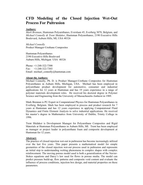
CFD Modeling of the Closed Injection Wet-Out Process For Pultrusion
CFD Modeling of the Closed Injection Wet-Out Process For Pultrusion
CFD Modeling of the Closed Injection Wet-Out Process For Pultrusion

You also want an ePaper? Increase the reach of your titles
YUMPU automatically turns print PDFs into web optimized ePapers that Google loves.
<strong>CFD</strong> <strong>Modeling</strong> <strong>of</strong> <strong>the</strong> <strong>Closed</strong> <strong>Injection</strong> <strong>Wet</strong>-<strong>Out</strong><br />
<strong>Process</strong> <strong>For</strong> <strong>Pultrusion</strong><br />
Authors:<br />
Mark Brennan, Huntsman Polyurethanes, Everslaan 45, Everberg 3078, Belgium, and<br />
Michael Connolly & Trent Shidaker, Huntsman Polyurethanes, 2190 Executive Hills<br />
Boulevard, Auburn Hills, MI, USA 48326<br />
Michael Connolly<br />
Product Manager-Urethane Composites<br />
Huntsman Polyurethanes<br />
2190 Executive Hills Boulevard<br />
Auburn Hills, Michigan USA 48326<br />
Phone: +1-248-322-7300<br />
Fax: +1-248-322-7303<br />
Email: michael_connolly@huntsman.com<br />
About <strong>the</strong> Authors:<br />
Michael Connolly, Ph. D. is Product Manager-Urethane Composites for Huntsman<br />
Polyurethanes in Auburn Hills, Michigan, USA. Michael has been employed in<br />
polyurethane product development for automotive, consumer and industrial<br />
applications for 12 years at Huntsman and has 19 years experience in a range <strong>of</strong><br />
polymer materials development roles. He received his doctoral degree in Polymer<br />
Science and Engineering from <strong>the</strong> University <strong>of</strong> Massachusetts-Amherst in 1989.<br />
Mark Brennan is PU Expert in Computational Physics for Huntsman Polyurethanes in<br />
Everberg, Belgium. Mark has been employed in process and product research for 7<br />
years at Huntsman and has 12 years experience in applying Computational Fluid<br />
Dynamics and Finite Element Analysis to solve industrial applications. He received<br />
his master s degree in Ma<strong>the</strong>matics from University <strong>of</strong> Dublin, Trinity College in<br />
1996.<br />
Trent Shidaker is Development Manager for Polyurethane Composites and Rigid<br />
Materials at Huntsman Polyurethanes in Auburn Hills, MI. Trent has been employed<br />
as manager or project leader in polyurethane foam and composite development at<br />
Huntsman for 12 years.<br />
Abstract:<br />
The practice <strong>of</strong> closed injection wet-out in pultrusion has become increasingly utilized<br />
over <strong>the</strong> last five years. This paper presents a ma<strong>the</strong>matical model for simple<br />
geometries <strong>of</strong> <strong>the</strong> closed injection wet-out process used in pultrusion and represents<br />
an initial step to understanding wetting phenomena in complex shapes with complex<br />
reinforcement. The moving porous model used is both a generalization <strong>of</strong> <strong>the</strong> Navier-<br />
Stokes equations and Darcy s law used for flows in porous media. The model can<br />
predict pressure build-up, flow patterns and composite void content and evaluate <strong>the</strong><br />
influence <strong>of</strong> process conditions, injection box design, and material properties on <strong>the</strong>se<br />
parameters.
INTRODUCTION<br />
Over <strong>the</strong> past decade, <strong>the</strong> global<br />
pultrusion industry has increasingly<br />
adopted closed injection wet-out for<br />
pr<strong>of</strong>ile processing. This trend has been<br />
driven by awareness <strong>of</strong> worker safety<br />
and mandates by regulatory agencies to<br />
reduce volatile organic compounds<br />
(VOC s) and by <strong>the</strong> availability <strong>of</strong> new<br />
resin technology. Polyurethane (PU)<br />
resins, in particular, have become an<br />
accepted alternate technology which<br />
contain no VOC s, especially for<br />
applications requiring high strength<br />
and durability combined with <strong>the</strong><br />
potential for high pultrusion line<br />
speeds (Ref. 1-3 and references<br />
<strong>the</strong>rein). However, <strong>the</strong> relatively fast<br />
reactivity <strong>of</strong> PU resins requires<br />
processing via closed injection wetout.<br />
The complex pr<strong>of</strong>ile geometries and<br />
reinforcement schedules used in state<strong>of</strong>-<strong>the</strong>-art<br />
pr<strong>of</strong>iles make efficient wetout<br />
challenging in a constrained state<br />
within an injection box. This<br />
challenge is even greater for PU resins,<br />
considering <strong>the</strong>ir inherently fast<br />
reactivity. Hence, a more thorough<br />
understanding <strong>of</strong> wet-out dynamics in<br />
injection processing for pultrusion is<br />
needed to expand acceptance <strong>of</strong> this<br />
process for PU resins and accelerate its<br />
implementation.<br />
This report describes a ma<strong>the</strong>matical<br />
model for closed injection wet-out in<br />
<strong>the</strong> pultrusion process. The model<br />
predicts <strong>the</strong> impact <strong>of</strong> injection box<br />
geometry, process conditions, resin<br />
viscosity, reinforcement fraction and<br />
permeability on flow patterns, pressure<br />
pr<strong>of</strong>iles and final part density.<br />
EXPERIMENTAL<br />
<strong>CFD</strong> simulations were carried on an<br />
injection box for a die pr<strong>of</strong>ile<br />
dimension <strong>of</strong> 5.21cm x 0.648 cm<br />
(2.05 x 0.255 ). The line speeds were<br />
varied between 0.6 and 1.5 m/min (24<br />
to 60 inch/min) with injection box<br />
lengths from 30.5 to 53.3 cm (12 to<br />
21 ). Resin viscosity was varied<br />
between 600 and 2400 cP.<br />
Experimental pultrusion runs were<br />
made to verify <strong>the</strong> <strong>CFD</strong> results.<br />
RIMLine ® SK 97007 polyol and<br />
Suprasec ®<br />
9700 isocyanate and<br />
experimental variants were combined<br />
as <strong>the</strong> polyurethane matrix. Pr<strong>of</strong>iles<br />
were pultruded with 120 rovings for a<br />
total glass content <strong>of</strong> 77 wt% (60 vol<br />
%). A two-component metering unit<br />
(Electric Willie from GS<br />
Manufacturing) with gear pump flow<br />
control was used to ensure delivery <strong>of</strong><br />
<strong>the</strong> polyurethane resin at constant<br />
pressure. <strong>Injection</strong> boxes were<br />
fabricated using aluminum with HDPE<br />
guide plates having small holes to<br />
prevent resin leakage. Digital pressure<br />
transducers or pressure gauges were<br />
placed at ~2.5 cm (1 ) and ~10 cm (4 )<br />
from <strong>the</strong> die face as well as <strong>the</strong><br />
injection port. The typical injection<br />
box setup is shown in Figure 1.<br />
MATHEMATICAL MODEL<br />
Due to difficulty in modeling<br />
macroscopic transport <strong>of</strong> resin and<br />
reinforcement based on microscopic<br />
variation <strong>of</strong> velocity between fibers,<br />
<strong>the</strong> resin and reinforcement are better<br />
treated as a moving porous fiber<br />
medium. The moving porous model<br />
used is both a generalization <strong>of</strong> <strong>the</strong><br />
Navier-Stokes equations and Darcy s<br />
law used for flows in porous media.<br />
The balance equations for mass and<br />
momentum for steady incompressible<br />
flow are<br />
u<br />
0<br />
2<br />
u u p u S<br />
u, p, , , and S are <strong>the</strong> superficial<br />
velocity, pressure, density, viscosity<br />
and momentum sources, respectively.
The momentum sources, S, defining<br />
<strong>the</strong> moving porous medium are<br />
S u U<br />
K<br />
K, and U are <strong>the</strong> permeability tensor,<br />
porosity and velocity <strong>of</strong> <strong>the</strong> fiber<br />
bundle. The geometry <strong>of</strong> <strong>the</strong> injection<br />
box is shown in Figure 2. This<br />
approach is similar to <strong>the</strong> model<br />
demonstrated by Jeswani et al. [Ref. 4]<br />
The approach is a phenomenological<br />
one with <strong>the</strong> main assumption being<br />
that <strong>the</strong> surface tension effects are not<br />
important or are captured in <strong>the</strong><br />
permeability tensor. The<br />
reinforcements are initially dry and <strong>the</strong><br />
resin must penetrate <strong>the</strong> fiber bundles.<br />
Capillary forces <strong>of</strong> attraction and<br />
repulsion act at <strong>the</strong> flow front. These<br />
forces, which depend on <strong>the</strong> surface<br />
tension <strong>of</strong> <strong>the</strong> resin and on its ability to<br />
adhere to <strong>the</strong> surface <strong>of</strong> <strong>the</strong> fibers, have<br />
an effect <strong>of</strong> increasing or decreasing<br />
<strong>the</strong> effective pressure at <strong>the</strong> resin front.<br />
However, <strong>the</strong>y are assumed to be<br />
sufficiently small to be neglected by<br />
<strong>the</strong> model. This assumption can be<br />
checked with micro-scale modeling <strong>of</strong><br />
air-resin interface flow in fiber<br />
bundles.<br />
A fur<strong>the</strong>r assumption in <strong>the</strong> model is<br />
that degree <strong>of</strong> conversion and hence<br />
build-up <strong>of</strong> viscosity is small and,<br />
hence, can be ignored in <strong>the</strong> injection<br />
box region. It is also assumed that<br />
<strong>the</strong>re is no shear rate dependence <strong>of</strong><br />
viscosity. These complexities can be<br />
added to <strong>the</strong> model without great<br />
difficulty.<br />
Porosity and Fiber Volume Fraction<br />
The porosity <strong>of</strong> <strong>the</strong> fiber bundle varies<br />
with axial distance in <strong>the</strong> model<br />
1 Vf ( z)<br />
hence, <strong>the</strong> stream wise and transverse<br />
permeability throughout <strong>the</strong> injection<br />
is not constant. An example <strong>of</strong> porosity<br />
variation throughout <strong>the</strong> injection box<br />
is shown in Figure 3.<br />
Permeability Model<br />
The Gebart permeability model [Ref.<br />
5] with a hexagonal fiber arrangement<br />
was chosen to model <strong>the</strong> permeability<br />
in both <strong>the</strong> axial and transverse fiber<br />
directions. The model is particularly<br />
suited to pultrusion processes as <strong>the</strong><br />
fibers are unidirectional. In <strong>the</strong> axial<br />
direction, <strong>the</strong> permeability is defined<br />
by<br />
K<br />
z<br />
2D<br />
2 3<br />
f<br />
2<br />
c<br />
(1 )<br />
where Df is <strong>the</strong> effective fiber diameter<br />
and c a model constant. The<br />
permeability in <strong>the</strong> transverse direction<br />
is<br />
K K<br />
x y<br />
C D<br />
V<br />
1<br />
2<br />
f f ,max<br />
1<br />
4 (1 )<br />
where Vf,max is <strong>the</strong> maximum volume<br />
fraction <strong>of</strong> fibers and C1 a model<br />
constant. Pr<strong>of</strong>iles <strong>of</strong> stream wise and<br />
transverse permeability are shown in<br />
Figure 4.<br />
Boundary Conditions<br />
Where <strong>the</strong> fiber reinforcement enters<br />
<strong>the</strong> injection box, <strong>the</strong> pressure is set to<br />
atmospheric pressure and a positive<br />
pressure is set at <strong>the</strong> injection port. At<br />
<strong>the</strong> exit <strong>of</strong> <strong>the</strong> computational domain, a<br />
small distance into <strong>the</strong> die, <strong>the</strong> axial<br />
velocity is set to <strong>the</strong> porosity times <strong>the</strong><br />
pull speed.<br />
5<br />
2
Flow Solver<br />
The ma<strong>the</strong>matical model was solved<br />
by <strong>the</strong> flow solver ANSYS-CFX 11.0<br />
with additional source terms added to<br />
account for <strong>the</strong> moving porous<br />
medium.<br />
RESULTS AND DISCUSSION<br />
Flow Patterns in <strong>the</strong> <strong>Injection</strong> Box<br />
Streamlines, created by releasing massless<br />
particles from <strong>the</strong> feed ports, show<br />
how <strong>the</strong> resin impregnates <strong>the</strong> fiber<br />
bundle in Figure 5. Resin injected<br />
through <strong>the</strong> feed ports spreads over <strong>the</strong><br />
top <strong>of</strong> <strong>the</strong> bundle, <strong>the</strong>n impregnates<br />
into it and finally is pulled through <strong>the</strong><br />
injection box, achieving good wet-out.<br />
The streamlines are colored to indicate<br />
<strong>the</strong> pressure gradient.<br />
Pressure Pr<strong>of</strong>iles in <strong>the</strong> <strong>Injection</strong> Box<br />
Figure 6 shows <strong>the</strong> centerline pressure<br />
pr<strong>of</strong>iles in <strong>the</strong> injection box for<br />
different line speeds. As expected <strong>the</strong><br />
final pressure rise increases with line<br />
speed. <strong>For</strong> example, at a line speed <strong>of</strong><br />
0.6 m/min, <strong>the</strong> pressure rise at <strong>the</strong> die<br />
face is 23 bar, rising to 57 bar at a line<br />
speed <strong>of</strong> 1.5 m/min. The experimental<br />
results (blue squares in Fig. 6) compare<br />
favorably with <strong>the</strong> <strong>CFD</strong> results at ~10<br />
cm from <strong>the</strong> die face. However, <strong>the</strong><br />
injection box pressure measured at<br />
~2.5 cm from <strong>the</strong> die face is much<br />
higher than predicted. The model<br />
assumes a uniform reinforcement<br />
matrix and does not take into account<br />
factors such as roving twist or<br />
resin/fiber interactions which would<br />
likely be magnified in <strong>the</strong> constrained<br />
state near <strong>the</strong> die face. Fur<strong>the</strong>r<br />
experimental work is in progress to<br />
verify and expand on <strong>the</strong>se results.<br />
Figure 7 shows <strong>the</strong> influence <strong>of</strong> <strong>the</strong><br />
viscosity <strong>of</strong> <strong>the</strong> resin, glass fraction,<br />
box length and box height (i.e., <strong>the</strong><br />
effective taper angle <strong>of</strong> <strong>the</strong> box) on <strong>the</strong><br />
final pressure rise in <strong>the</strong> injection box.<br />
As expected for a fully wet-out part,<br />
this relationship is linear for viscosity<br />
and box length. While <strong>the</strong> physics <strong>of</strong><br />
<strong>the</strong> pressure rise are not completely<br />
understood, <strong>the</strong> model predicts nonlinear<br />
relationships for box height and<br />
glass fraction. The model can also look<br />
at <strong>the</strong> influence <strong>of</strong> o<strong>the</strong>r geometrical<br />
factors such as injection location(s)<br />
and o<strong>the</strong>r operating parameters<br />
including injection pressure on <strong>the</strong><br />
pressure pr<strong>of</strong>iles in <strong>the</strong> box.<br />
Fiber <strong>Wet</strong>-<strong>Out</strong> in <strong>the</strong> <strong>Injection</strong> Box<br />
Figure 8 shows <strong>the</strong> resin flow-front<br />
development in <strong>the</strong> injection box. To<br />
achieve good wet-out, both flow fronts<br />
should reach <strong>the</strong> center <strong>of</strong> <strong>the</strong> fiber<br />
bundle but also spread to all regions <strong>of</strong><br />
<strong>the</strong> injection box. In Figure 8, <strong>the</strong> resin<br />
is colored to indicate residence time in<br />
<strong>the</strong> box. It can be observed in this case<br />
that <strong>the</strong> pultruded part is completely<br />
wet-out by <strong>the</strong> time it enters <strong>the</strong> die.<br />
The model can be used to illustrate<br />
process conditions under which pr<strong>of</strong>ile<br />
wet-out becomes an issue. It can also<br />
be used to evaluate <strong>the</strong> influence <strong>of</strong><br />
injection box geometry and operating<br />
parameters such as injection pressure<br />
on wetting efficiency.
CONCLUSIONS<br />
A ma<strong>the</strong>matical model <strong>of</strong> a pultrusion<br />
injection box has been created. A<br />
permeability model for unidirectional<br />
reinforcements based on porosity and<br />
direction has been used. The model<br />
can predict injection box pressure<br />
pr<strong>of</strong>iles and flow patterns giving an<br />
estimation <strong>of</strong> reinforcement wet-out.<br />
The model has proven to be versatile<br />
and can evaluate a number <strong>of</strong> factors<br />
influencing process performance<br />
including injection box geometry, <strong>the</strong><br />
number and location <strong>of</strong> <strong>the</strong> injection<br />
ports, injection pressure, line speed,<br />
resin physical properties, fiber<br />
permeability and fiber fraction on<br />
pressure rise in <strong>the</strong> injection box.<br />
The model predicts <strong>the</strong> appropriate<br />
trends when compared with<br />
experimental data and experience.<br />
Fur<strong>the</strong>r experimental work is planned<br />
to verify additional geometric and<br />
process variations. With <strong>the</strong> use <strong>of</strong> this<br />
model, <strong>the</strong> typical empirical approach<br />
taken with injection box development<br />
can be reduced or eliminated. Hence,<br />
<strong>the</strong> development time line can be<br />
shortened and adoption <strong>of</strong> closed<br />
injection wet-out and PU resin systems<br />
may be accelerated in <strong>the</strong> pultrusion<br />
industry.<br />
All information contained herein<br />
is provided "as is" without any<br />
warranties, express or implied, and<br />
under no circumstances shall <strong>the</strong><br />
authors or Huntsman be liable for any<br />
damages <strong>of</strong> any nature whatsoever<br />
resulting from <strong>the</strong> use or reliance upon<br />
such information. Nothing contain in<br />
this publication should be construed as<br />
a license under any intellectual<br />
property right <strong>of</strong> any entity, or as a<br />
suggestion, recommendation, or<br />
authorization to take any action that<br />
would infringe any patent. The term<br />
"Huntsman" is used herein for<br />
convenience only, and refers to<br />
Huntsman Corporation, its direct and<br />
indirect affiliates, and <strong>the</strong>ir employees,<br />
<strong>of</strong>ficers, and directors.<br />
REFERENCES<br />
1. Connolly, M., King, J.P., Shidaker,<br />
T.A., Duncan, A.C., Pultruding<br />
Polyurethane Composite Pr<strong>of</strong>iles:<br />
Practical Guidelines for <strong>Injection</strong><br />
Box Design, Component Metering<br />
Equipment and <strong>Process</strong>ing,<br />
Proceedings <strong>of</strong> Composites 2005,<br />
American Composites<br />
Manufacturers Association, Sept.<br />
2005.<br />
2. Connolly, M., King, J.P., Shidaker,<br />
T.A., Duncan, A.C., <strong>Process</strong>ing<br />
and Characterization <strong>of</strong> Pultruded<br />
Polyurethane Composites,<br />
Proceedings <strong>of</strong> <strong>the</strong> 8 th World<br />
<strong>Pultrusion</strong> Conference, European<br />
Pultruders Technical Association,<br />
March 2006.<br />
3. Connolly, M., King, J.P., Shidaker,<br />
T.A., Duncan, A.C.,<br />
Characterization <strong>of</strong> Pultruded<br />
Polyurethane Composites:<br />
Environmental Exposure and<br />
Component Assembly Testing,<br />
Proceedings <strong>of</strong> Composites 2006,<br />
American Composites<br />
Manufacturers Association, Oct.<br />
2006.<br />
4. Jeswani, A.L., Roux, J.A.,<br />
Vaughan, J.G., Impact <strong>of</strong> Axial<br />
Location <strong>of</strong> <strong>the</strong> <strong>Injection</strong> Slot for<br />
High Pull Speed Resin <strong>Injection</strong><br />
<strong>Pultrusion</strong>, Proceedings <strong>of</strong> <strong>the</strong> 1 st<br />
Global <strong>Pultrusion</strong> Conference,<br />
Baltimore, MD, June 2006.<br />
5. Gebart, B.R., Permeability <strong>of</strong><br />
Unidirectional Reinforcements for<br />
RTM, Journal <strong>of</strong> Composite<br />
Materials, 26: 1100-1133 (1992).
Mixhead<br />
Static Mixers<br />
Pressure<br />
Guage at<br />
Tee Inlet<br />
Digital<br />
Pressure<br />
Transducer<br />
Fiberglass Rovings Mounting Bracket<br />
Figure 1: Typical <strong>Injection</strong> Box Setup<br />
Figure 2: <strong>CFD</strong> model <strong>of</strong> injection box
Figure 3: Porosity variation <strong>of</strong> <strong>the</strong> fiber bundle in <strong>the</strong> injection box<br />
Figure 4: Stream wise and transverse permeability pr<strong>of</strong>iles in <strong>the</strong> injection box
Figure 5: Flow streamlines in <strong>the</strong> injection box colored with pressure for a line<br />
speed <strong>of</strong> 1.2 m/min<br />
Figure 6: Centerline pressure pr<strong>of</strong>iles for 45.7 cm (18 ) injection box at different<br />
line speeds with a viscosity <strong>of</strong> 1200 cP
Figure 7: Influence <strong>of</strong> viscosity, glass fraction, box length and box height on final<br />
pressure rise in <strong>the</strong> injection box<br />
Figure 8: Development <strong>of</strong> resin flow front indicating fiber wet-out