2003 - Astronomia - Università degli Studi di Firenze
2003 - Astronomia - Università degli Studi di Firenze
2003 - Astronomia - Università degli Studi di Firenze

Create successful ePaper yourself
Turn your PDF publications into a flip-book with our unique Google optimized e-Paper software.
EUSO filter<br />
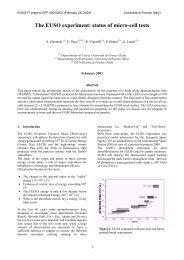
In <strong>2003</strong> year XUVLab has stu<strong>di</strong>ed optical properties, again in collaboration with INOA and INFN, several<br />
solutions of <strong>di</strong>fferent coatings on Schott BG3 absorption filter that has been selected as the baseline<br />
filter for EUSO detectors, in particular the transmittance at various incidence angles. Those<br />
measurements are necessary to taking into account that a UV filter must be arranged in front of the<br />
MAPMT to limit photons wavelength at range of nitrogen fluorescence, between 300nm and 400nm. The<br />
Schott BG3 absorption filter has been selected as the baseline filter for EUSO detectors. This filter will have a<br />
multi-layer coating that cuts off transmission sharply above 400 nm and is anti-reflective [Gambicorti at<br />
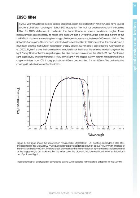
el., <strong>2003</strong>]. Figure 1 shows the transmission characteristics of the filter at the extreme incident angles of the<br />
light. For light incident at the largest angles, the blue and red curves show the effect of S and P polarized<br />
light respectively. This filter transmits >90% of the light in the region 330nm-400nm for most incidence<br />
angles with less than 10% throughput above 440nm and less than 1% at 460nm. The anti-reflective<br />
coating virtually eliminates reflection losses.<br />
Transmittance (%)<br />
100<br />
90<br />
80<br />
70<br />
60<br />
50<br />
40<br />
30<br />
20<br />
10<br />
Figure 1. This figure shows the transmission measured of MgF2/HfO2 + AR coating applied to a BG3 filter.<br />
The ad<strong>di</strong>tion of the MgF2/HfO2 multilayer coating provides a shape cut-off above 400 nm with little loss of<br />
transmission below 400 nm. The two black curves show the transmission of light at normal incidence and<br />
at the largest angle of incidence. For the latter case, the blue and red curves show the transmission for S<br />
and P polarized light.<br />
These coatings will be stu<strong>di</strong>ed of developed during 2004 coupled to the optical adapters for the MAPMT.<br />
XUVLab activity summary <strong>2003</strong><br />
INFN B2: Transmittance<br />
0<br />
200 220 240 260 280 300 320 340 360 380 400 420 440 460 480 500 520 540 5<br />
Wavelength<br />
optical design and testing 10