draft document IEC 61400-25-6 - scc-online.de
draft document IEC 61400-25-6 - scc-online.de
draft document IEC 61400-25-6 - scc-online.de

You also want an ePaper? Increase the reach of your titles
YUMPU automatically turns print PDFs into web optimized ePapers that Google loves.
1<br />
2<br />
3<br />
4<br />
5<br />
6<br />
7<br />
8<br />
9<br />
10<br />
11<br />
12<br />
13<br />
14<br />
15<br />
16<br />
17<br />
18<br />
19<br />
20<br />
21<br />
22<br />
23<br />
24<br />
<strong>25</strong><br />
WD for <strong>61400</strong>-<strong>25</strong>-6 © <strong>IEC</strong>: 2007 – 1 –<br />
Updated proposal for <strong>IEC</strong><strong>61400</strong>-<strong>25</strong>-6 to be discussed in further <strong>de</strong>tails at the<br />
working group meeting in Madrid <strong>25</strong>.- 26.09.2007 – Carsten An<strong>de</strong>rsson & Knud<br />
Johansen.<br />
WIND TURBINES<br />
Part <strong>25</strong>-6:<br />
Communications for monitoring and control of wind power plants –<br />
Logical no<strong>de</strong> classes and data classes for condition monitoring<br />
Version: <strong>61400</strong>-<strong>25</strong>-6_R0-4-WD_2007-09-11, rev. 2<br />
Version <strong>61400</strong>-<strong>25</strong>-6_R0-4-WD_2007-09-11
1<br />
2<br />
3<br />
4<br />
5<br />
6<br />
7<br />
8<br />
9<br />
10<br />
11<br />
12<br />
13<br />
14<br />
15<br />
16<br />
17<br />
18<br />
19<br />
20<br />
21<br />
22<br />
23<br />
24<br />
<strong>25</strong><br />
26<br />
27<br />
28<br />
29<br />
30<br />
31<br />
32<br />
33<br />
34<br />
35<br />
36<br />
37<br />
38<br />
39<br />
40<br />
41<br />
42<br />
WD for <strong>61400</strong>-<strong>25</strong>-6 © <strong>IEC</strong>: 2007 – 2 –<br />
CONTENTS<br />
FOREWORD.........................................................................................................................4<br />
INTRODUCTION...................................................................................................................5<br />
1 Scope ............................................................................................................................9<br />
1.1 Setup and control of condition monitoring systems ........................................................10<br />
1.2 Condition monitoring techniques ...................................................................................10<br />
2 Terms and <strong>de</strong>finitions ...................................................................................................12<br />
3 Abbreviated terms ........................................................................................................14<br />
4 General ........................................................................................................................17<br />
4.1 Condition Monitoring as related to the logical no<strong>de</strong> classes ...........................................17<br />
4.2 Logical No<strong>de</strong> Classes related to condition monitoring ....................................................17<br />
4.3 Condition monitoring data .............................................................................................17<br />
4.4 Condition Monitoring Data Types ..................................................................................18<br />
4.5 Condition Monitoring and active power bins...................................................................19<br />
4.6 Mo<strong>de</strong>lling the information from the wind turbine.............................................................19<br />
4.7 Mandatory Measurements.............................................................................................21<br />
5 Wind Turbine Condition Monitoring Information .............................................................22<br />
5.1 General Structure of WCON Class information ..............................................................22<br />
5.2 Example of a WCON Class ...........................................................................................22<br />
5.3 Examples of WCON Class logical no<strong>de</strong> addresses from the table: .................................<strong>25</strong><br />
5.4 Examples of WCON Classes not covered by the example..............................................<strong>25</strong><br />
6 Common Data Classes .................................................................................................<strong>25</strong><br />
6.1 Basic Concepts for Common Data Classes....................................................................<strong>25</strong><br />
6.2 Structure of Common Data Classes...............................................................................27<br />
6.3 Common Data Class Attribute types..............................................................................27<br />
6.3.1 Common Data Class attributes types inherited from <strong>IEC</strong> <strong>61400</strong>-<strong>25</strong>-2 .........27<br />
6.4 Common data Class attributes types inherited from <strong>IEC</strong> 61850-7-3 ................................27<br />
6.5 Vector ..........................................................................................................................27<br />
6.6 Point ............................................................................................................................27<br />
6.7 RangeConfig ................................................................................................................27<br />
6.8 ScaledValueConfig .......................................................................................................28<br />
6.9 Wind turbine condition monitoring specific common data classes (CDC) ........................28<br />
6.9.1 Scalar Value (SV) ....................................................................................28<br />
6.9.2 Vector Value (VV) ....................................................................................28<br />
6.9.3 Scalar Value Array (SVA) .........................................................................29<br />
6.9.4 Setpoint Array (SPA)................................................................................29<br />
6.9.5 Data File (DAF)........................................................................................29<br />
Annex A (Informative) Application of Shaft and Bearing position numbering for<br />
annotating frequency spectra.......................................................................................30<br />
A.1 General ........................................................................................................................30<br />
A.2 Example with gearbox...................................................................................................30<br />
Version <strong>61400</strong>-<strong>25</strong>-6_R0-4-WD_2007-09-11
1<br />
2<br />
3<br />
4<br />
5<br />
6<br />
7<br />
WD for <strong>61400</strong>-<strong>25</strong>-6 © <strong>IEC</strong>: 2007 – 3 –<br />
Annex B (Informative) Examples of trend histories of mandatory measurements to be<br />
used for due diligence etc.............................................................................................31<br />
B.1 Trend history of Generator measurements.....................................................................31<br />
Figure 1 – The two major information and information exchange mo<strong>de</strong>ls ................................6<br />
Figure 2 – Conceptual information and information exchange mo<strong>de</strong>l of <strong>IEC</strong> <strong>61400</strong>-<strong>25</strong>-6 .........7<br />
Version <strong>61400</strong>-<strong>25</strong>-6_R0-4-WD_2007-09-11
1<br />
2<br />
3<br />
4<br />
5<br />
6<br />
7<br />
8<br />
9<br />
10<br />
11<br />
12<br />
13<br />
14<br />
15<br />
16<br />
17<br />
18<br />
19<br />
20<br />
21<br />
22<br />
23<br />
24<br />
<strong>25</strong><br />
26<br />
27<br />
28<br />
29<br />
30<br />
31<br />
32<br />
33<br />
34<br />
35<br />
36<br />
37<br />
38<br />
39<br />
40<br />
41<br />
42<br />
43<br />
44<br />
45<br />
46<br />
WD for <strong>61400</strong>-<strong>25</strong>-6 © <strong>IEC</strong>: 2007 – 4 –<br />
INTERNATIONAL ELECTROTECHNICAL COMMISSION<br />
____________<br />
WIND TURBINES –<br />
Part <strong>25</strong>-6:<br />
Communications for monitoring and control of wind power plants –<br />
Logical no<strong>de</strong> classes and data classes for condition monitoring<br />
FOREWORD<br />
1) The <strong>IEC</strong> (International Electrotechnical Commission) is a worldwi<strong>de</strong> organisation for standardisation comprising<br />
all national electrotechnical committees (<strong>IEC</strong> National Committees). The object of the <strong>IEC</strong> is to promote<br />
international co-operation on all questions concerning standardisation in the electrical and electronic fields. To<br />
this end and in addition to other activities, the <strong>IEC</strong> publishes International Standards. Their preparation is<br />
entrusted to technical committees; any <strong>IEC</strong> National Committee interested in the subject <strong>de</strong>alt with may<br />
participate in this preparatory work. International, governmental and non-governmental organisations liaising<br />
with the <strong>IEC</strong> also participate in this preparation. The <strong>IEC</strong> collaborates closely with the International<br />
Organisation for Standardisation (ISO) in accordance with conditions <strong>de</strong>termined by agreement between the<br />
two organisations.<br />
2) The formal <strong>de</strong>cisions or agreements of the <strong>IEC</strong> on technical matters express, as nearly as possible, an<br />
international consensus of opinion on the relevant subjects since each technical committee has representation<br />
from all interested National Committees.<br />
3) The <strong>document</strong>s produced have the form of recommendations for international use and are published in the form<br />
of standards, technical specifications, technical reports or gui<strong>de</strong>s and they are accepted by the National<br />
Committees in that sense.<br />
4) In or<strong>de</strong>r to promote international unification, <strong>IEC</strong> National Committees un<strong>de</strong>rtake to apply <strong>IEC</strong> International<br />
Standards transparently to the maximum extent possible in their national and regional standards. Any<br />
divergence between the <strong>IEC</strong> Standard and the corresponding national or regional standard shall be clearly<br />
indicated in the latter.<br />
5) The <strong>IEC</strong> provi<strong>de</strong>s no marking procedure to indicate its approval and cannot be ren<strong>de</strong>red responsible for any<br />
equipment <strong>de</strong>clared to be in conformity with one of its standards.<br />
6) Attention is drawn to the possibility that some of the elements of this International Standard may be the subject<br />
of patent rights. The <strong>IEC</strong> shall not be held responsible for i<strong>de</strong>ntifying any or all such patent rights.<br />
Recipients of this <strong>document</strong> are invited to submit, with their comments, notification of<br />
any relevant patent rights of which they are aware and to provi<strong>de</strong> supporting <strong>document</strong>ation.<br />
This publication has been <strong>draft</strong>ed in accordance with the ISO/<strong>IEC</strong> Directives, Part 2.<br />
<strong>IEC</strong> <strong>61400</strong>-<strong>25</strong> consists of the following parts, un<strong>de</strong>r the general title Communications for<br />
monitoring and control of wind power plants:<br />
Part <strong>25</strong>-1: Overall <strong>de</strong>scription on principles and mo<strong>de</strong>ls<br />
Part <strong>25</strong>-2: Information mo<strong>de</strong>ls<br />
Part <strong>25</strong>-3: Information Exchange Mo<strong>de</strong>ls<br />
Part <strong>25</strong>-4: Mapping to communication profile<br />
Part <strong>25</strong>-5: Conformance testing<br />
Part <strong>25</strong>-6: Logical no<strong>de</strong> classes and data classes for condition monitoring 1<br />
Version <strong>61400</strong>-<strong>25</strong>-6_R0-4-WD_2007-09-11
1<br />
2<br />
3<br />
4<br />
5<br />
6<br />
7<br />
8<br />
9<br />
10<br />
11<br />
12<br />
13<br />
14<br />
15<br />
16<br />
17<br />
18<br />
19<br />
20<br />
21<br />
22<br />
23<br />
24<br />
<strong>25</strong><br />
26<br />
27<br />
28<br />
29<br />
30<br />
31<br />
32<br />
33<br />
34<br />
35<br />
36<br />
37<br />
38<br />
39<br />
WD for <strong>61400</strong>-<strong>25</strong>-6 © <strong>IEC</strong>: 2007 – 5 –<br />
INTRODUCTION<br />
<strong>IEC</strong> <strong>61400</strong>-<strong>25</strong> <strong>de</strong>fines information mo<strong>de</strong>ls and information exchange mo<strong>de</strong>ls for monitoring<br />
and control of wind power plants. The mo<strong>de</strong>lling approach (for information mo<strong>de</strong>ls and information<br />
exchange mo<strong>de</strong>ls) of <strong>IEC</strong> <strong>61400</strong>-<strong>25</strong>-2 and <strong>IEC</strong> <strong>61400</strong>-<strong>25</strong>-4 uses abstract <strong>de</strong>finitions of<br />
classes and services such that the specifications are in<strong>de</strong>pen<strong>de</strong>nt of specific communication<br />
protocol stacks, implementations, and operating systems. The mapping of these abstract <strong>de</strong>finitions<br />
to specific communication profiles is <strong>de</strong>fined in <strong>IEC</strong> <strong>61400</strong>-<strong>25</strong>-4.<br />
The <strong>de</strong>finitions in parts <strong>IEC</strong> <strong>61400</strong>-<strong>25</strong>-1 to <strong>IEC</strong> <strong>61400</strong>-<strong>25</strong>-5 apply also for this part 6 of the<br />
standard series<br />
The purpose of this <strong>draft</strong> of Part 6 is to <strong>de</strong>fine an information mo<strong>de</strong>l for condition monitoring<br />
information and to <strong>de</strong>fine the necessary extensions to the already existing parts of <strong>IEC</strong> <strong>61400</strong>-<br />
<strong>25</strong> in or<strong>de</strong>r to handle information related to condition monitoring of wind turbines.<br />
Condition monitoring <strong>de</strong>finition<br />
In the context of this standard condition monitoring is taken to mean a process with the purpose<br />
of watching machinery for a period of time in or<strong>de</strong>r to evaluate the state of the machinery<br />
and any changes to it, in or<strong>de</strong>r to <strong>de</strong>tect early signs of impending failure.<br />
Condition monitoring is most frequently used as a Predictive or Condition-Based Maintenance<br />
technique (CBM). However, there are other predictive maintenance techniques that can also<br />
be used, including the use of the Human Senses (look, listen, feel, smell etc.) or Machine Performance<br />
Monitoring techniques. These would not be consi<strong>de</strong>red to be condition monitoring<br />
for the purposes of this standard.<br />
Condition monitoring techniques<br />
These inclu<strong>de</strong>, but are not limited to techniques such as:<br />
• Vibration measurements and analysis<br />
• Oil analysis<br />
• Temperature measurement<br />
• Strain gauge measurement<br />
• Etc.<br />
Equipment can be monitored by using advanced instrumentation as well as using a manual<br />
process.<br />
Condition monitoring <strong>de</strong>vices<br />
The information consumed and generated by condition monitoring functions may be located in<br />
different physical <strong>de</strong>vices. Some information may be located in the turbine controller <strong>de</strong>vice<br />
(TCD) while other information may be located in an additional condition monitoring <strong>de</strong>vice<br />
(CMD). Various actors may request to exchange data located in the TCD or CMD. A SCADA<br />
<strong>de</strong>vice may want to receive data from the TCD or CMD; a CMD may want to receive data from<br />
TCD and vice versa. The information exchange between any two <strong>de</strong>vices requires the use of<br />
information exchange services <strong>de</strong>fined in <strong>IEC</strong> <strong>61400</strong>-<strong>25</strong>-3 or ad<strong>de</strong>d in this part 6. A summary<br />
of the above is <strong>de</strong>picted in Figure 1.<br />
Version <strong>61400</strong>-<strong>25</strong>-6_R0-4-WD_2007-09-11
1<br />
2<br />
3<br />
4<br />
5<br />
6<br />
7<br />
8<br />
9<br />
10<br />
11<br />
12<br />
13<br />
14<br />
15<br />
16<br />
WD for <strong>61400</strong>-<strong>25</strong>-6 © <strong>IEC</strong>: 2007 – 6 –<br />
Actors like<br />
SCADA, Operator, Network<br />
Control Center, …<br />
<strong>25</strong>-xx<br />
Information<br />
Exchange<br />
…<br />
Logical No<strong>de</strong>s and Data<br />
<strong>25</strong>-3/4<br />
Information<br />
Scope of<br />
standard<br />
<strong>25</strong>-3/4 & 6<br />
Information<br />
Exchange<br />
Exchange<br />
Turbine control <strong>de</strong>vice or function<br />
with Logical No<strong>de</strong>s and Data (<strong>25</strong>-2)<br />
Actors like SCADA, Operator, Network<br />
Control Center, Owner, Maintenance, …<br />
<strong>25</strong>-3/4 & 6<br />
Information<br />
Exchange<br />
Condition monitoring <strong>de</strong>vice or function<br />
with Logical No<strong>de</strong>s and Data (<strong>25</strong>-2/6)<br />
Gearbox<br />
Generator<br />
Brake<br />
Tower<br />
Version <strong>61400</strong>-<strong>25</strong>-6_R0-4-WD_2007-09-11<br />
TC/CM<br />
Figure 1 – The two major information and information exchange mo<strong>de</strong>ls<br />
The use case of having the CM functions located in the TCD is a special use case. That use<br />
case does not require information exchange services for the information exchange between<br />
the CM functions and TC functions. The case of having separate <strong>de</strong>vices is the more comprehensive<br />
use case. This is used as the basic topology in this part of the standard. The special<br />
case of both functions in one <strong>de</strong>vice could be <strong>de</strong>rived from the most general use case.<br />
It may also be required to build a hierarchical mo<strong>de</strong>l of TC and CM <strong>de</strong>vices/functions. The last<br />
but one box in the figure indicates that case. A simple CMD (providing measured values and<br />
status information and very basic monitoring capabilities) may be located close to the turbine.<br />
A second CMD may be located in the wind park control room. This CMD may retrieve information<br />
from the un<strong>de</strong>rlying CMD or TCD and may further process and analyse the measured values<br />
and status information.<br />
Note 1: The location of <strong>de</strong>vices and functions (more centralized or <strong>de</strong>centralized topology) is outsi<strong>de</strong> the scope of<br />
this standard.<br />
Figure 2 below <strong>de</strong>picts the basic concept of the information and information exchange mo<strong>de</strong>ls.<br />
…<br />
…
1<br />
2<br />
3<br />
4<br />
5<br />
6<br />
7<br />
8<br />
9<br />
10<br />
WD for <strong>61400</strong>-<strong>25</strong>-6 © <strong>IEC</strong>: 2007 – 7 –<br />
Outsi<strong>de</strong><br />
scope<br />
Actor<br />
e. g.<br />
Analysis,<br />
SCADA,<br />
Maintenance<br />
part of central<br />
Condition Monitoring<br />
Client<br />
Information exchange<br />
Information exchange<br />
mo<strong>de</strong>l (get, set, report,<br />
mo<strong>de</strong>l (get, set, report,<br />
log, control, publish /<br />
log, control, publish /<br />
subscribe, …)<br />
subscribe, …)<br />
<strong>IEC</strong> <strong>61400</strong>-<strong>25</strong>-3<br />
<strong>IEC</strong> <strong>61400</strong>-<strong>25</strong>-3<br />
Wind power plant<br />
Wind power plant<br />
information mo<strong>de</strong>l<br />
information mo<strong>de</strong>l<br />
<strong>IEC</strong> <strong>61400</strong>-<strong>25</strong>-2/-6<br />
<strong>IEC</strong> <strong>61400</strong>-<strong>25</strong>-2/-6<br />
Server<br />
Information exchange<br />
Information exchange<br />
mo<strong>de</strong>l (get, set, report,<br />
mo<strong>de</strong>l (get, set, report,<br />
log, control, publish /<br />
log, control, publish /<br />
subscribe, …)<br />
subscribe, …)<br />
<strong>IEC</strong> <strong>61400</strong>-<strong>25</strong>-3<br />
<strong>IEC</strong> <strong>61400</strong>-<strong>25</strong>-3<br />
Wind power plant<br />
Wind power plant<br />
information mo<strong>de</strong>l<br />
information mo<strong>de</strong>l<br />
(aging, …)<br />
(aging, …)<br />
<strong>IEC</strong> <strong>61400</strong>-<strong>25</strong>-6<br />
<strong>IEC</strong> <strong>61400</strong>-<strong>25</strong>-6<br />
Communication mo<strong>de</strong>l of <strong>IEC</strong> <strong>61400</strong>-<strong>25</strong><br />
Messaging through<br />
Messaging through<br />
mapping to<br />
mapping to<br />
communication<br />
communication<br />
profile (Records,<br />
profile (Records,<br />
Read, write, ...<br />
Read, write, ...<br />
message)<br />
message)<br />
<strong>IEC</strong> <strong>61400</strong>-<strong>25</strong>-4<br />
<strong>IEC</strong> <strong>61400</strong>-<strong>25</strong>-4<br />
part of turbine Controller<br />
Server<br />
Wind power plant<br />
Wind power plant<br />
information mo<strong>de</strong>l<br />
information mo<strong>de</strong>l<br />
(rotor speed, break<br />
(rotor speed, break<br />
status, total power<br />
status, total power<br />
production, …)<br />
production, …)<br />
<strong>IEC</strong> <strong>61400</strong>-<strong>25</strong>-2<br />
<strong>IEC</strong> <strong>61400</strong>-<strong>25</strong>-2<br />
Information exchange<br />
Information exchange<br />
mo<strong>de</strong>l (get, set, report,<br />
mo<strong>de</strong>l (get, set, report,<br />
log, control, publish /<br />
log, control, publish /<br />
subscribe, …)<br />
subscribe, …)<br />
<strong>IEC</strong> <strong>61400</strong>-<strong>25</strong>-3<br />
<strong>IEC</strong> <strong>61400</strong>-<strong>25</strong>-3<br />
part of local Condition<br />
Monitoring<br />
Server<br />
Information exchange<br />
Information exchange<br />
mo<strong>de</strong>l (get, set, report,<br />
mo<strong>de</strong>l (get, set, report,<br />
log, control, publish /<br />
log, control, publish /<br />
subscribe, …)<br />
subscribe, …)<br />
<strong>IEC</strong> <strong>61400</strong>-<strong>25</strong>-3<br />
<strong>IEC</strong> <strong>61400</strong>-<strong>25</strong>-3<br />
Wind power plant<br />
Wind power plant<br />
information mo<strong>de</strong>l<br />
information mo<strong>de</strong>l<br />
(Vibration samples,<br />
(Vibration samples,<br />
aging, …)<br />
aging, …)<br />
<strong>IEC</strong> <strong>61400</strong>-<strong>25</strong>-6<br />
<strong>IEC</strong> <strong>61400</strong>-<strong>25</strong>-6<br />
Version <strong>61400</strong>-<strong>25</strong>-6_R0-4-WD_2007-09-11<br />
Outsi<strong>de</strong><br />
scope<br />
Wind power<br />
plant<br />
component<br />
e. g. wind turbine<br />
Application<br />
Figure 2 – Conceptual information and information exchange mo<strong>de</strong>l of <strong>IEC</strong> <strong>61400</strong>-<strong>25</strong>-6<br />
Condition Monitoring Value Chain<br />
In automatic condition monitoring, when any monitored and pre<strong>de</strong>fined condition limit is excee<strong>de</strong>d,<br />
a signal or output is turned on. This signal can be used by a Condition Monitoring<br />
Supervision function to generate actionable information which can be used by a service organisation<br />
to create work or<strong>de</strong>rs. Figure 3 below illustrates the value chain of a system using<br />
condition monitoring to perform condition based maintenance.<br />
The figure illustrates how data are refined and concentrated through the value chain, ending<br />
up wit the ultimate goal of condition based maintenance the work or<strong>de</strong>r to the service staff.
1<br />
2<br />
3<br />
4<br />
5<br />
6<br />
7<br />
8<br />
WD for <strong>61400</strong>-<strong>25</strong>-6 © <strong>IEC</strong>: 2007 – 8 –<br />
Figure 3 – The value chain of condition based maintenance<br />
Figure 3 illustrates the scope of <strong>IEC</strong> <strong>61400</strong>-<strong>25</strong>-6 which is the two first levels of the value<br />
chain. That is, the Local condition monitoring and data acquisition performed by the condition<br />
monitoring <strong>de</strong>vice located in the wind turbine and the central condition monitoring performed<br />
by the Central Condition Monitoring Server. The <strong>de</strong>creasing sizes of the boxes in the value<br />
chain illustrate the data reduction and the data refinement process.<br />
Version <strong>61400</strong>-<strong>25</strong>-6_R0-4-WD_2007-09-11
1<br />
2<br />
3<br />
4<br />
5<br />
6<br />
7<br />
8<br />
9<br />
10<br />
11<br />
12<br />
13<br />
14<br />
15<br />
16<br />
17<br />
18<br />
19<br />
20<br />
21<br />
22<br />
23<br />
24<br />
<strong>25</strong><br />
26<br />
27<br />
28<br />
WD for <strong>61400</strong>-<strong>25</strong>-6 © <strong>IEC</strong>: 2007 – 9 –<br />
WIND TURBINES –<br />
Part <strong>25</strong>-6:<br />
Communications for monitoring and control of wind power plants –<br />
Logical no<strong>de</strong> classes and data classes for condition monitoring<br />
1 Scope<br />
This standard <strong>de</strong>fines the information mo<strong>de</strong>ls related to condition monitoring for wind power<br />
plants and the information exchange of data values related to these mo<strong>de</strong>ls.<br />
Condition monitoring relies mainly on the following kinds of information:<br />
1. Time waveform records (samples) of a specific time interval to be exchanged in real-time<br />
or by files for analysis (e.g. acceleration, position <strong>de</strong>tection, speed, stress <strong>de</strong>tection)<br />
2. Status information and measurements (synchronized with the waveform records) representing<br />
the Turbine Operation Conditions.<br />
3. Results of Time waveform record analysis of vibration data (scalar values, array values,<br />
statistical values, historical (statistical) values, counters and status information).<br />
4. Results of oil <strong>de</strong>bris analysis.<br />
It is the purpose of this standard to mo<strong>de</strong>l condition monitoring information by using the mo<strong>de</strong>lling<br />
approach as <strong>de</strong>scribed in clause 6.2.2 of <strong>61400</strong>-<strong>25</strong>-1 and by extending the already existing<br />
information mo<strong>de</strong>l as indicated in Clause 6 of <strong>61400</strong>-<strong>25</strong>-2.<br />
Fig 4 – Structure of wind power plant information mo<strong>de</strong>l<br />
By the use of already <strong>de</strong>fined logical no<strong>de</strong>s and the table of abbreviated terms as <strong>de</strong>fined in<br />
<strong>IEC</strong> <strong>61400</strong>-<strong>25</strong>-2, and by <strong>de</strong>scribing a logical no<strong>de</strong> WCON for data related to condition monitoring<br />
data classes, data for condition monitoring classes shall be mapped by extending the<br />
table of abbreviated terms from <strong>61400</strong>-<strong>25</strong>-2 with abbreviations related to condition monitoring.<br />
Refer to section 3 of this <strong>document</strong>.<br />
Note 1: Proposals for additional abbreviations are marked with yellow in the table.<br />
Version <strong>61400</strong>-<strong>25</strong>-6_R0-4-WD_2007-09-11
1<br />
2<br />
3<br />
4<br />
5<br />
6<br />
7<br />
8<br />
9<br />
10<br />
11<br />
12<br />
13<br />
14<br />
15<br />
16<br />
17<br />
18<br />
19<br />
20<br />
21<br />
22<br />
23<br />
24<br />
<strong>25</strong><br />
26<br />
WD for <strong>61400</strong>-<strong>25</strong>-6 © <strong>IEC</strong>: 2007 – 10 –<br />
This standard <strong>de</strong>scribes the data mo<strong>de</strong>l for the following categories of data to be retrieved<br />
from the wind turbine condition monitoring system:<br />
1. Scalar data<br />
2. Arrays of Scalar data<br />
3. Vector data<br />
4. Data files<br />
5. Trigger Options<br />
Note 2: Trigger options refer to <strong>IEC</strong> <strong>61400</strong>-<strong>25</strong>-2 Table <strong>25</strong>. This is a notification that a state or value change has occurred.<br />
1.1 Setup and control of condition monitoring systems<br />
It is not within the scope of the standard to setup and control the condition monitoring system<br />
1.2 Condition monitoring techniques<br />
It is not within the scope of this standard to <strong>de</strong>fine how to implement the condition monitoring<br />
of wind turbines and to specify allowable limits for measured data. This work is done by other<br />
standardisation committees such as “Richtlinie VDI 3834 Messung und Beurteilung <strong>de</strong>r<br />
mechanischen Schwingungen von Win<strong>de</strong>nergieanlagen und <strong>de</strong>ren Komponenten.<br />
Impacts on other parts of <strong>IEC</strong> <strong>61400</strong>-<strong>25</strong><br />
This proposal for <strong>61400</strong>-<strong>25</strong>-6 will have some implications on the following parts of <strong>61400</strong>-<strong>25</strong><br />
1. Extension of the Logical No<strong>de</strong> Classes as <strong>de</strong>fined in <strong>IEC</strong> <strong>61400</strong>-<strong>25</strong>-2 to comprise the information<br />
related to condition monitoring systems. WTUR for status information of the<br />
condition monitoring <strong>de</strong>vice and WALM for inclusion of alarms generated by the condition<br />
monitoring system into the general alarm overview.<br />
2. Extensions of the Information Exchange Mo<strong>de</strong>l as <strong>de</strong>fined in <strong>IEC</strong> <strong>61400</strong>-<strong>25</strong>-3 to handle the<br />
Data file entity and the Vector entity.<br />
3. Extension of the Mapping to communication profile as <strong>de</strong>fined in <strong>IEC</strong> <strong>61400</strong>-<strong>25</strong>-4 to handle<br />
the Data File entity and the Vector entity.<br />
Version <strong>61400</strong>-<strong>25</strong>-6_R0-4-WD_2007-09-11
1<br />
2<br />
3<br />
4<br />
5<br />
6<br />
7<br />
8<br />
9<br />
10<br />
11<br />
12<br />
13<br />
14<br />
15<br />
16<br />
17<br />
18<br />
19<br />
WD for <strong>61400</strong>-<strong>25</strong>-6 © <strong>IEC</strong>: 2007 – 11 –<br />
Normative references<br />
The following referenced <strong>document</strong>s are indispensable for the application of this <strong>document</strong>.<br />
For dated references, only the edition cited applies. For undated references, the latest edition<br />
of the referenced <strong>document</strong> (including any amendments) applies.<br />
<strong>IEC</strong> <strong>61400</strong>-<strong>25</strong>-1:2006, Communications for monitoring and control of wind power plants –<br />
Overall <strong>de</strong>scription on principles and mo<strong>de</strong>ls<br />
<strong>IEC</strong> <strong>61400</strong>-<strong>25</strong>-2:2006, Communications for monitoring and control of wind power plants -- Information<br />
Exchange Mo<strong>de</strong>l<br />
<strong>IEC</strong> <strong>61400</strong>-<strong>25</strong>-3:2006, Communications for monitoring and control of wind power plants -- Information<br />
Mo<strong>de</strong>ls<br />
<strong>IEC</strong> <strong>61400</strong>-<strong>25</strong>-4, Communications for monitoring and control of wind power plants -- Mapping<br />
to communication profile1<br />
<strong>IEC</strong> 61850-7-4 Amendment 1, Communication networks and systems in substations – Part 7-<br />
4: Basic communication structure for substations and fee<strong>de</strong>r equipment – Compatible logical<br />
no<strong>de</strong> classes and data classes<br />
<strong>IEC</strong> 60<strong>25</strong>5-24:2001, Electrical relays – Part 24: Common format for transient data exchange<br />
(COMTRADE) for power systems<br />
ISO 10816/1-6 “Mechanical vibration – Evaluation of machine vibration by measurements on<br />
non-rotating parts”<br />
—————————<br />
1 To be published<br />
Version <strong>61400</strong>-<strong>25</strong>-6_R0-4-WD_2007-09-11
1<br />
2<br />
3<br />
4<br />
5<br />
6<br />
7<br />
8<br />
9<br />
10<br />
11<br />
12<br />
13<br />
14<br />
15<br />
16<br />
17<br />
18<br />
19<br />
20<br />
21<br />
22<br />
23<br />
24<br />
<strong>25</strong><br />
26<br />
27<br />
28<br />
29<br />
30<br />
31<br />
32<br />
33<br />
34<br />
35<br />
36<br />
37<br />
38<br />
39<br />
40<br />
41<br />
42<br />
43<br />
WD for <strong>61400</strong>-<strong>25</strong>-6 © <strong>IEC</strong>: 2007 – 12 –<br />
2 Terms and <strong>de</strong>finitions<br />
For the purpose of this <strong>document</strong>, the terms and <strong>de</strong>finitions <strong>de</strong>fined in part <strong>IEC</strong> <strong>61400</strong>-<strong>25</strong>-1<br />
and the following apply.<br />
Editor’s note: The following list is not complete. This section shall be updated in case more terms and <strong>de</strong>finitions<br />
will be required for part <strong>25</strong>-6.<br />
2.1<br />
actor<br />
Any entity that receives (sends) data values from (to) another <strong>de</strong>vice. Examples of actors<br />
could be SCADA systems, maintenance systems, owner, etc.<br />
2.2<br />
mandatory<br />
Defined content must be provi<strong>de</strong>d in compliance to this standard.<br />
2.3<br />
Optional<br />
Defined content can be optionally provi<strong>de</strong>d in compliance to this standard.<br />
2.4<br />
Conditional<br />
Defined content can be provi<strong>de</strong>d in compliance to this standard if certain conditions are present.<br />
2.5<br />
Scalar value<br />
A Scalar value is a quantity which can be <strong>de</strong>scribed by a single number, such as a temperature.<br />
Scalar values are very suitable for historical trending and statistical purposes.<br />
2.6<br />
Data file<br />
In a computer system, a data file is an entity of data available to system users (including the<br />
system itself and its application programs) that is capable of being manipulated as an entity<br />
(for example, moved from one file directory to another). The file must have a unique name<br />
within its own directory. Some operating systems and applications <strong>de</strong>scribe files with given<br />
formats by giving them a particular file name suffix. (The file name suffix is also known as a<br />
file name extension.)<br />
2.7<br />
Peak Value<br />
The Peak Value is the maximum excursion of a time wave form from its mean value within a<br />
specific time interval.<br />
2.8<br />
Peak-to-Peak Value<br />
The difference between the positive and negative extreme values of a time wave form.<br />
2.9<br />
Crest Factor<br />
The crest factor of a waveform is the ratio of the peak value of a time waveform to the RMS<br />
value of the time wave form within a specific time interval. It is also sometimes called the<br />
"peak-to-RMS-ratio".<br />
Version <strong>61400</strong>-<strong>25</strong>-6_R0-4-WD_2007-09-11
1<br />
2<br />
3<br />
4<br />
5<br />
6<br />
7<br />
8<br />
9<br />
10<br />
11<br />
12<br />
13<br />
14<br />
15<br />
16<br />
17<br />
18<br />
19<br />
20<br />
21<br />
22<br />
23<br />
24<br />
<strong>25</strong><br />
26<br />
27<br />
28<br />
29<br />
30<br />
31<br />
32<br />
33<br />
34<br />
35<br />
36<br />
37<br />
38<br />
39<br />
40<br />
WD for <strong>61400</strong>-<strong>25</strong>-6 © <strong>IEC</strong>: 2007 – 13 –<br />
2.10<br />
RMS Value<br />
RMS stands for Root Mean Square, and is a measure of the level of a signal. It is calculated<br />
by squaring the instantaneous value of the signal, averaging the squared values over time,<br />
and taking the square root of the average value. The RMS value is the value which is used to<br />
calculate the energy or power in a signal.<br />
2.11<br />
Band pass (BP)<br />
A filter that only passes energy between two frequencies which are called the lower and upper<br />
cut-off frequencies. Band pass filters can be fixed, where the cut-off frequencies are constant,<br />
and can be variable, where the cut-off frequencies are varied with time.<br />
2.12<br />
Or<strong>de</strong>r<br />
An or<strong>de</strong>r is a multiple of some reference frequency. An FFT spectrum plot displayed in or<strong>de</strong>rs<br />
will have multiples of running speed along the horizontal axis. Or<strong>de</strong>rs are commonly referred<br />
to as 1x for running speed, 2x for twice the running speed, and so on. When an Or<strong>de</strong>r is an integral<br />
number of the running speed it may be referred to as a harmonic of the running speed.<br />
E.g. 2x may be referred to as the 2nd harmonic of the running speed.<br />
2.13<br />
Or<strong>de</strong>r Analysis<br />
Ability to study the amplitu<strong>de</strong> changes of specific signals that are related to the rotation of the<br />
<strong>de</strong>vice un<strong>de</strong>r observation.<br />
2.14<br />
UFF 58<br />
De-facto standard file format for storing noise and vibration information in the area of the car<br />
industry. The format can be read by analyzers from several vendors on the market<br />
2.15<br />
ISO 10816 1-6<br />
A wi<strong>de</strong>ly used standard for evaluation of vibration measurements. It consists of 6 parts.<br />
ISO10816-1 is the basic <strong>document</strong> <strong>de</strong>scribing the general requirements for evaluating machinery<br />
vibration using casing and/or foundation measurements. Subsequent parts of each series<br />
of <strong>document</strong>s apply to different classes and types of machinery, and inclu<strong>de</strong> specific<br />
evaluation criteria used to assess vibration severity. The Vibration Magnitu<strong>de</strong> is <strong>de</strong>fined within<br />
this group of standards as the maximum value of the broadband RMS value (acceleration, velocity<br />
or displacement) in the specified frequency range (typically from 10 to 1,000 Hz).<br />
2.16<br />
HFBP – High Frequency Band Pass<br />
Overall measurement covering a high frequency range of 1 kHz – 10 kHz. Impacts from bearing<br />
faults often results in one or more resonance effects in the high frequency range. Measurements<br />
limited to this frequency range are therefore well suited for <strong>de</strong>tecting bearing faults.<br />
Version <strong>61400</strong>-<strong>25</strong>-6_R0-4-WD_2007-09-11
1<br />
2<br />
3<br />
4<br />
5<br />
6<br />
7<br />
8<br />
9<br />
10<br />
WD for <strong>61400</strong>-<strong>25</strong>-6 © <strong>IEC</strong>: 2007 – 14 –<br />
3 Abbreviated terms<br />
CDC Common Data Class<br />
CM Condition Monitoring (Function)<br />
CMD Condition Monitoring Device<br />
DC Data Class<br />
ING Common Data Class for Integer Setting value (see <strong>IEC</strong> 61850-7-3)<br />
LCB Log Control Block<br />
LD Logical Device<br />
LN logical no<strong>de</strong><br />
LPHD Logical no<strong>de</strong> Physical Device Information<br />
RCB Report Control Block<br />
RMS Root Mean Square<br />
SAV Common Data Class for Sampled Analogue Values (see <strong>IEC</strong> 61850-7-3)<br />
SHS Statistical and Historical Statistical data (as <strong>de</strong>fined in <strong>IEC</strong> <strong>61400</strong>-<strong>25</strong>-2 Annex A)<br />
SMV Sampled Measured Values; some times short: SV = Sampled Values<br />
TC Turbine Controller (Function)<br />
TCD Turbine Controller Device<br />
TOC Turbine Operation Conditions<br />
WPP Wind Power Plant<br />
WT Wind Turbine<br />
Abbreviated terms used to build names of data classes found in LNs shall be as listed below.<br />
Editor’s note The following list has been copied from Draft <strong>IEC</strong> <strong>61400</strong>-<strong>25</strong>-2 (CDV). The list needs to be updated<br />
in case we need new terms/abbreviations for part <strong>25</strong>-6.<br />
EXAMPLE RotPos is constructed by using two names “Rot” which stands for Rotor and “Pos” which stands for<br />
“Position”. Thus the concatenated name represents a “Rotor Position”.<br />
Note 3: The items of the table marked in yellow are examples of abbreviations to be used for creating data classes<br />
for the WCON logical no<strong>de</strong>.<br />
Term Description<br />
A Current<br />
AC AC<br />
Ack Acknowledge<br />
Acs Access<br />
Act Actual<br />
Alm Alarm<br />
An Analogue<br />
Ane Anemometer<br />
Ang Angle<br />
Alt Altitu<strong>de</strong><br />
At Active (real)<br />
Atv Activate<br />
Av Average<br />
Avl Availability<br />
Version <strong>61400</strong>-<strong>25</strong>-6_R0-4-WD_2007-09-11<br />
Term Description<br />
Az Azimuth<br />
Bec Beacon<br />
Bl Bla<strong>de</strong><br />
Blk Blocked<br />
Brg Bearing<br />
Brk Brake<br />
Cab Cable<br />
Ccw Counter clockwise<br />
Ch Characteristic<br />
Chg Change<br />
Chk Check<br />
Chrg Charge<br />
Cl Cooling<br />
Cm Command
WD for <strong>61400</strong>-<strong>25</strong>-6 © <strong>IEC</strong>: 2007 – 15 –<br />
Term Description<br />
Cnv Converter<br />
Ct Counting<br />
Ctl Control<br />
Cw Clockwise<br />
d Description<br />
Dat Data<br />
Db Deadband<br />
DC DC (Direct Current)<br />
Dcl Dc-link<br />
Dec Decrease<br />
Dehum De-humidifier<br />
Del Delta<br />
Det Detection<br />
Dir Direction<br />
Disp Displacement<br />
Dly Daily<br />
Dmd Demand<br />
Drv Drive<br />
Dn Down<br />
Egy Energy<br />
Elev Elevator<br />
Emg Emergency<br />
En Enable<br />
Ent Entrance<br />
Ety Empty<br />
Evt Event<br />
Ex External<br />
Ext Excitation<br />
Flsh Flash<br />
Flt Fault<br />
Ftr Filter<br />
Gbx Gearbox<br />
Gra Gradient<br />
Gri Grid<br />
Gn Generator<br />
Gs Grease<br />
Hi High<br />
Hly Hourly<br />
Hor Horizontal<br />
Ht Heating<br />
Htex Heat-exchanger<br />
Hum Humidity<br />
Hy Hydraulic<br />
Hz Frequency<br />
Version <strong>61400</strong>-<strong>25</strong>-6_R0-4-WD_2007-09-11<br />
Term Description<br />
Ice Ice<br />
Id I<strong>de</strong>ntifier<br />
Idl Idling<br />
Inc Increase<br />
Inj Injection<br />
Inl Inline<br />
Inlet Inlet<br />
Inst Instantaneous<br />
Intl Internal<br />
Lev Level<br />
Log Log<br />
Lift Lift<br />
Lim Limit<br />
Lo Low<br />
Lu Lubrication<br />
Lum Luminosity<br />
Man Manual<br />
Max Maximum<br />
Met Meteorological<br />
Min Minimum<br />
Mly Monthly<br />
Mod Mo<strong>de</strong><br />
Mx Measurement<br />
Mul Multiplier<br />
Nac Nacelle<br />
Num Number (size)<br />
Of Off line<br />
Oil Oil<br />
Op Operate, Operating<br />
Oper Operator<br />
Ov Over<br />
Per Period, Periodic<br />
PF Power factor<br />
Ph Phase<br />
Pmp Pump<br />
Pl Plant<br />
Plu Pollution<br />
Pos Position<br />
Pres Pressure<br />
Prod Production<br />
Pt Pitch<br />
Ptr Pointer<br />
Pwr Power<br />
q Quality
WD for <strong>61400</strong>-<strong>25</strong>-6 © <strong>IEC</strong>: 2007 – 16 –<br />
Term Description<br />
Rdy Ready<br />
Rep Report<br />
Rms Root-mean-square<br />
Rng Range<br />
Roof Roof<br />
Rot Rotor (windturbine)<br />
Rs Reset<br />
React Reactive<br />
Rtr Rotor (generator)<br />
Sdv Standard <strong>de</strong>viation<br />
Sev Severity<br />
Seq Sequence<br />
Shf Shaft<br />
Smk Smoke<br />
Smp Sampled<br />
Sp Setpoint<br />
Spd Speed<br />
St Status<br />
Sta Stator<br />
Stdby Standby<br />
Stop Stop<br />
Str Start<br />
Sw Switch<br />
Sys System<br />
T Timestamp<br />
Tm Timer<br />
Tmp Temperature<br />
Tot Total<br />
Tow Tower<br />
Tra Transient<br />
Trf Transformer<br />
Trg Trigger<br />
Torq Torque<br />
Tur Turbine<br />
Un Un<strong>de</strong>r<br />
Urg Urgent<br />
V Voltage<br />
VA Apparent power<br />
Val Value<br />
Vals Values<br />
Ver Vertical<br />
Vib Vibration<br />
Vis Visibility<br />
Wd Wind (power)<br />
Version <strong>61400</strong>-<strong>25</strong>-6_R0-4-WD_2007-09-11<br />
1<br />
Term Description<br />
Wly Weekly<br />
Wup Windup<br />
Xdir X-direction<br />
Ydir Y-direction<br />
Yly Yearly<br />
Yw Yaw<br />
Lt Lateral<br />
Pc Power Class<br />
Up Up (opposite to Down)<br />
St State<br />
Acc Accelerometer<br />
1Ps 1’st Planetary Stage<br />
2Ps 2’nd Planetary Stage<br />
Iss Intermediate Speed Stage<br />
Hss High Speed Stage<br />
Stg Stage (1, 2, 3 .. etc.)<br />
Fr Front<br />
Rr Rear<br />
Ax Axial<br />
Ra Radial<br />
Up Up<br />
Deb Debris<br />
Sld Structural Load
1<br />
2<br />
3<br />
4<br />
5<br />
6<br />
7<br />
8<br />
9<br />
10<br />
11<br />
12<br />
13<br />
14<br />
15<br />
16<br />
17<br />
18<br />
19<br />
20<br />
21<br />
22<br />
23<br />
24<br />
<strong>25</strong><br />
26<br />
27<br />
28<br />
WD for <strong>61400</strong>-<strong>25</strong>-6 © <strong>IEC</strong>: 2007 – 17 –<br />
4 General<br />
4.1 Condition Monitoring as related to the logical no<strong>de</strong> classes<br />
Values for condition monitoring can all be related to a particular part of the turbine, exactly as<br />
a SCADA value such as temperature can be related to a part of the turbine. Therefore the<br />
data mo<strong>de</strong>l as <strong>de</strong>scribed in <strong>61400</strong>-<strong>25</strong>-2 for the SCADA values can be applied to condition<br />
monitoring data.<br />
4.2 Logical No<strong>de</strong> Classes related to condition monitoring<br />
Table 1: Wind Turbine Condition Monitoring related no<strong>de</strong> classes:<br />
WTUR Wind turbine general information<br />
WALM Wind power plant alarm information<br />
WCON Wind condition monitoring information<br />
The WTUR no<strong>de</strong> class is related to wind turbine condition monitoring as the condition monitoring<br />
system may refer to information from this class.<br />
The WALM no<strong>de</strong> class is related to wind turbine condition monitoring as alarms from the condition<br />
monitoring system may be referred to by this class.<br />
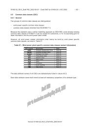
4.3 Condition monitoring data<br />
As shown in the table below, each of the data categories as specified by the Common Data<br />
Classes <strong>de</strong>fined in the scope of this standard can be used by a number of different data types<br />
used in a condition monitoring system.<br />
In particular, when using vibration monitoring it is possible to <strong>de</strong>rive several measurement<br />
values of different data types from the transducer signal by using filtering and other post<br />
processing techniques. The table below shows some examples of relationships between data<br />
categories as specified by the Common Data Classes and the data types of the measurements.<br />
Table 2: Wind Turbine Condition Monitoring Specific information categories<br />
Data type examples Category<br />
ISO RMS according to ISO 10816 Scalar Value<br />
Crest Factor Scalar Value<br />
Band pass Value (E.g. picking up the tooth meshing frequency) Scalar Value<br />
Power Spectrum (Auto spectrum) result of an FFT analysis Array of Scalar Values<br />
Envelope Spectrum (result of an FFT analysis of a pre-processed time waveform) Array of Scalar Values<br />
Time Wave Form Array of Scalar Values<br />
Filtered Time Wave Form Array of Scalar Values<br />
Picture Data File<br />
Thermo graphic Data Data File<br />
Time Wave form on ASCII format Data File<br />
Hi, HiHi, Lo, LoLo Trigger Option<br />
Danger, Alert Trigger Option<br />
Alarm, Warning Trigger Option<br />
The data types used for condition monitoring are many and may be <strong>de</strong>veloped for specific application<br />
and their number may increase as new <strong>de</strong>velopment goes on. The data categories<br />
are more general, there are not so many and the number of different data categories is more<br />
static.<br />
The figure below illustrates the relationship between Category, Data Type and Measured Values.<br />
Version <strong>61400</strong>-<strong>25</strong>-6_R0-4-WD_2007-09-11
1<br />
2<br />
3<br />
4<br />
5<br />
6<br />
7<br />
8<br />
9<br />
10<br />
11<br />
12<br />
13<br />
14<br />
15<br />
16<br />
17<br />
18<br />
WD for <strong>61400</strong>-<strong>25</strong>-6 © <strong>IEC</strong>: 2007 – 18 –<br />
Figure 5 – Relationship between Data category, Data Type and measured values<br />
4.4 Condition Monitoring Data Types<br />
The data types to be used for monitoring wind turbines shall be divi<strong>de</strong>d between a group of<br />
data types <strong>de</strong>fined as mandatory by this standard and a group which are optional and vendor<br />
specific.<br />
The objective of the mandatory data types is to create a uniform background for evaluating<br />
the state of a turbine. Note! This standard does not specify any recommen<strong>de</strong>d levels of these<br />
data. This is subject for other standards or for internal recommendations <strong>de</strong>veloped by individual<br />
turbine operators.<br />
The objective of the vendor specific data types are to adapt to the fact that different vendors<br />
have <strong>de</strong>veloped different philosophies for monitoring wind turbines and for allowing the future<br />
use of monitoring techniques which may not have been invented yet<br />
The data types specified for the condition monitoring system for a particular part of the turbine<br />
shall be assigned a unique number as shown in the table below. This data type is then used<br />
in the data mo<strong>de</strong>l as reference when referring to measurements of a certain data type. For the<br />
same location on the machine there may exist several measurements of different data types.<br />
Table 3: Numbers used to <strong>de</strong>scribe measurement types: D11-D99 is Vibration Related Values – Vendor Specific<br />
Data Type Number Abbreviation. Explanation<br />
Reserved Data Types<br />
Vendor specific data types<br />
D01 RMS Overall RMS according to ISO 10816<br />
D02 HFBP High Frequency Band pass. Range 1kHz – 10kHz.<br />
D03 TMF Tooth Meshing Frequency<br />
D04 2TMF 2 Or<strong>de</strong>r Tooth Meshing Frequency<br />
D05 3TMF 3 Or<strong>de</strong>r Tooth Meshing Frequency<br />
D06 1MA 1 st Or<strong>de</strong>r Magnitu<strong>de</strong><br />
D07 2MA 2 nd Or<strong>de</strong>r Magnitu<strong>de</strong><br />
D08 3MA 3 rd Or<strong>de</strong>r Magnitu<strong>de</strong><br />
D09 TwRMS Used for Tower Measurements. Range 0.1Hz – 100Hz.<br />
D10 - Not Used<br />
D11 BP 4kHz-6kHz<br />
D12 BP 100Hz – 500Hz<br />
D13 .<br />
D14 .<br />
D15 .<br />
D16 BPFO Ball Passing Frequency Outer Ring<br />
D17 BPFI Ball Passing Frequency Inner Ring<br />
D18 FFT 0-10kHz<br />
D19 TWF Time Wave Form<br />
.<br />
.<br />
Version <strong>61400</strong>-<strong>25</strong>-6_R0-4-WD_2007-09-11
1<br />
2<br />
3<br />
4<br />
5<br />
6<br />
7<br />
8<br />
9<br />
10<br />
11<br />
12<br />
13<br />
14<br />
15<br />
16<br />
17<br />
18<br />
19<br />
20<br />
21<br />
22<br />
23<br />
24<br />
<strong>25</strong><br />
26<br />
27<br />
28<br />
WD for <strong>61400</strong>-<strong>25</strong>-6 © <strong>IEC</strong>: 2007 – 19 –<br />
4.5 Condition Monitoring and active power bins<br />
A wind turbine in principle operates over a wi<strong>de</strong> range of wind speeds causing a large range<br />
of loads on the tower, bla<strong>de</strong>s and related mechanical structures. An adaptive monitoring technique<br />
is often applied to secure a higher <strong>de</strong>gree of reliability and repeatability of measurements<br />
used to <strong>de</strong>tect <strong>de</strong>veloping faults in the full operating range, thus reducing the risk of<br />
false alarms. In or<strong>de</strong>r to adapt to the varying operating conditions, data can be stored in several<br />
“active power bins”. The basic principle of condition monitoring is to compare new measurements<br />
with old. The effect of changing operating conditions can be limited by only comparing<br />
data belonging to the same “active power bin.<br />
Active power are used for the adaptive monitoring technique rather than the wind speed as<br />
the vibration level measured on the turbine components are closely related to the active<br />
power production of the turbine. Using the active power also ensures that vibration measurements<br />
only are recor<strong>de</strong>d when the turbine is producing.<br />
Fig. 6 – Active power bin concept. Example of vibration data which is individually compared<br />
to alarm limits for five different “active power bins” with individual alarm trigger<br />
levels.<br />
4.6 Mo<strong>de</strong>lling the information from the wind turbine<br />
When referring condition monitoring information to a wind turbine it is necessary in many<br />
cases to be able to relate a measurement to a specific location on the turbine.<br />
E.g. A tooth meshing frequency (TMF) must be related to a specific shaft of the gearbox and<br />
the vibration level of the outer ring frequency of a bearing (BPFO) must be related to a specific<br />
shaft and a bearing position on that shaft.<br />
The schematic illustration below shows the principle of the shaft and bearing numbering used<br />
to relate a particular measurement to a location on the turbine. The numbering of the shafts<br />
and bearings are done with increasing numbering downwind direction, following the transmission<br />
of the force from the wind turbine bla<strong>de</strong>s. Note! The numbering also applies to other machine<br />
structures than the one shown in this section.<br />
Version <strong>61400</strong>-<strong>25</strong>-6_R0-4-WD_2007-09-11
1<br />
2<br />
3<br />
4<br />
5<br />
6<br />
7<br />
8<br />
9<br />
10<br />
11<br />
12<br />
13<br />
14<br />
15<br />
16<br />
17<br />
18<br />
19<br />
20<br />
21<br />
22<br />
23<br />
24<br />
<strong>25</strong><br />
26<br />
WD for <strong>61400</strong>-<strong>25</strong>-6 © <strong>IEC</strong>: 2007 – 20 –<br />
Fig. 7 - A schematic view of a wind turbine showing the shaft and bearing numbering<br />
principle.<br />
Shaft Number Bearing Position<br />
1 Main Shaft 1.1 Main bearing<br />
2 Carrier 2.1 Carrier Bearing<br />
3, 4, 5 Planet Shaft 1, 2 and 3 3.1, 4.1, 5.1 Plant Bearings<br />
6 Sun Shaft 6.1, 6.2 Sun Shaft Bearings<br />
7 Intermediate Shaft 7.1, 7.2 Intermediate Shaft Bearings<br />
8 High Speed Shaft 8.1, 8.2 High Speed Shaft bearings<br />
9 Generator Shaft 9.1, 9.2 Generator Shaft Bearings<br />
Note: An example from a wind turbine without a gearbox might be placed here for illustration<br />
of the large variety of mechanical <strong>de</strong>signs on the market.<br />
The following convention shall be used when referring to wind turbine vibration measurements:<br />
1) Overall vibration levels or Band pass measurements covering a wi<strong>de</strong> frequency range<br />
measured by transducers located on the different parts of the turbine cannot be related to<br />
specific shafts or bearings. Such measurements shall be i<strong>de</strong>ntified by the location of the<br />
sensor using the abbreviated terms <strong>de</strong>fined in section 3, and the name or number of the<br />
particular measurement. Refer to Example 1 below.<br />
2) Vibration levels which can be referred to a specific shaft, such as a tooth meshing frequency<br />
or or<strong>de</strong>r measurements shall be referred to by the shaft number. As an option the<br />
shaft number can be prece<strong>de</strong>d by the abbreviation as specified in section 3, if <strong>de</strong>sired. Refer<br />
to Example 2 below.<br />
3) Vibration levels which can be referred to a specific bearing, such as the Ball Passing Frequency<br />
of the Outer ring shall be referred to by the shaft number and bearing position. Refer<br />
to Example 3 below.<br />
Examples:<br />
1) The Overall RMS level measured by the transducer on the Intermediate Stage of the<br />
gearbox shall be referred to as: Iss.RMS.<br />
As the RMS is a standardized measurement type it can be referred to by its name.<br />
Version <strong>61400</strong>-<strong>25</strong>-6_R0-4-WD_2007-09-11
1<br />
2<br />
3<br />
4<br />
5<br />
6<br />
7<br />
8<br />
9<br />
10<br />
11<br />
12<br />
13<br />
14<br />
15<br />
16<br />
17<br />
18<br />
19<br />
20<br />
21<br />
22<br />
23<br />
24<br />
<strong>25</strong><br />
WD for <strong>61400</strong>-<strong>25</strong>-6 © <strong>IEC</strong>: 2007 – 21 –<br />
2) The vibration level of the Tooth Meshing Frequency of the Intermediate Shaft shall be referred<br />
to as: 7.TMF or Iss.7.TMF<br />
As the TMF is a standardized measurement type it can be referred by its name.<br />
3) The vibration level of the Ball Passing Frequency Outer Ring of the downwind bearing of<br />
the Intermediate Shaft shall be referred to as: 7.2.D16. or Iss.7.2.D16.<br />
The number “16” refers to table 3 of the previous section. As the BPFO is a vendor specified<br />
measurement it is referred to by its number.<br />
4.7 Mandatory Measurements<br />
The objective of the mandatory measurements is to provi<strong>de</strong> a way of evaluating the overall<br />
state of a wind turbine without going into diagnostic <strong>de</strong>tails. The selected data types are well<br />
suited for long term trending to study the <strong>de</strong>velopment in the vibration levels. It is beyond the<br />
scope of this standard to specify for example max. allowable limit values for these measurements.<br />
Defining specific levels for vibrations can be applicable for turbine operators and vendors e.g.<br />
in the following situations:<br />
• When a warranty period start<br />
• When a warranty period expires<br />
• When main components of the WTG is retrofitted or exchanged.<br />
• When a turbine operator is making a due diligence before acquiring a wind power plant<br />
• When benchmarking wind power plants and wind turbines<br />
The table below lists the proposed mandatory measurements for each turbine stage:<br />
Planetary Stages<br />
Data Type Number Abbreviation Explanation<br />
D01 RMS Overall RMS after the ISO-10816 standard (10Hz -1000Hz)<br />
D02 HFBP High Frequency Bandpass (1kHz – 10kHz)<br />
D03 TMF Tooth Meshing Frequency<br />
D04 2TMF 2 Or<strong>de</strong>r Tooth Meshing Frequency<br />
D05 3TMF 3 Or<strong>de</strong>r Tooth Meshing Frequency<br />
Other Gearbox Stages<br />
Data Type Number Abbreviation Explanation<br />
D01 RMS Overall RMS after the ISO standard<br />
D02 HFBP High Frequency Bandpass (1kHz – 10kHz)<br />
D03 TMF Tooth Meshing Frequency<br />
D04 2TMF 2 Or<strong>de</strong>r Tooth Meshing Frequency<br />
D05 3TMF 3 Or<strong>de</strong>r Tooth Meshing Frequency<br />
D06 1MA 1 st Magnitu<strong>de</strong><br />
D07 2MA 2 nd Magnitu<strong>de</strong><br />
Generator Drive End and Non Drive End<br />
Data Type Number Abbreviation Explanation<br />
D01 RMS Overall RMS after the ISO-10816 standard (10Hz -1000Hz)<br />
D02 HFBP High Frequency Band pass (1kHz – 10kHz)<br />
D06 1MA 1 st Magnitu<strong>de</strong><br />
D07 2MA 2 nd Magnitu<strong>de</strong><br />
Tower Down Wind and Tower Lateral<br />
Data Type Number Abbreviation Explanation<br />
D01 RMS Overall RMS after the ISO-10816 standard (10Hz -1000Hz)<br />
D06 1MA 1 st Or<strong>de</strong>r Magnitu<strong>de</strong><br />
Version <strong>61400</strong>-<strong>25</strong>-6_R0-4-WD_2007-09-11
1<br />
2<br />
3<br />
4<br />
5<br />
6<br />
7<br />
8<br />
9<br />
10<br />
11<br />
12<br />
13<br />
14<br />
15<br />
16<br />
17<br />
18<br />
19<br />
20<br />
21<br />
22<br />
23<br />
24<br />
<strong>25</strong><br />
26<br />
27<br />
WD for <strong>61400</strong>-<strong>25</strong>-6 © <strong>IEC</strong>: 2007 – 22 –<br />
D08 3MA 3 rd Or<strong>de</strong>r Magnitu<strong>de</strong><br />
5 Wind Turbine Condition Monitoring Information<br />
As shown in the table below the data class name for the condition monitoring parameters<br />
based upon vibration starts with the abbreviation “Vib”.<br />
5.1 General Structure of WCON Class information<br />
The general structure of the WCON class information is specified in the table below.<br />
WCON class<br />
Attribute Name Attr. Type Explanation M/O/C<br />
Specified by combining the optional and mandatory<br />
fields.<br />
Data<br />
Type of Information M<br />
Part of the turbine – Related Vibration Sensor O<br />
Data related to a turbine stage M/O<br />
Data related to a shaft M/O<br />
Data related to a shaft and bearing position O<br />
Explanation of WCON class content<br />
• This <strong>de</strong>notes the data class as specified by the abbreviations in section 3.<br />
E.g. Vib – Vibration.<br />
• This <strong>de</strong>notes the part of the turbine as specified by the abbreviations in section<br />
3. E.g. Hss – High Speed Stage<br />
• This <strong>de</strong>notes the vibration data type as specified in section 4.4. E.g. ISO<br />
RMS.<br />
• This <strong>de</strong>notes the shaft number as <strong>de</strong>fined in section 4.6.<br />
• This <strong>de</strong>notes the position of the bearing on the shaft as <strong>de</strong>fined in section 4.6.<br />
• This <strong>de</strong>fines the Bin where the measurement is stored as <strong>de</strong>fined in section 4.5.<br />
Bain may be active power bins for vibration measurements or bins for grouping particle<br />
sizes in oil <strong>de</strong>bris analysis. Bin number is left out for data types not related to a bin concept.<br />
• The Common Data Class type of the measured data.<br />
• M/O/C This <strong>de</strong>notes whether the information is Mandatory, Optional or Conditional.<br />
5.2 Example of a WCON Class<br />
The table below illustrates how a WCON Class may look for a simple wind turbine consisting<br />
of a main bearing, a three stage gearbox and a generator stage. In this example data has<br />
been grouped into 5 bins. Only fractions of the table are shown.<br />
Note 1: The table shall not be taken as a recommendation. It purely shows the principle of how a WCON class<br />
might be structured in practice.<br />
WCON class<br />
Attribute Name Attr. Type Explanation M/O<br />
Specified by combining the optional and mandatory<br />
fields.<br />
Data<br />
Vib Vibration M<br />
1Ps First planetary stage accelerometer M/O<br />
Version <strong>61400</strong>-<strong>25</strong>-6_R0-4-WD_2007-09-11
1<br />
WD for <strong>61400</strong>-<strong>25</strong>-6 © <strong>IEC</strong>: 2007 – 23 –<br />
RMS 1 SV Overall RMS of the 1 Pl. Stage M<br />
RMS 2 SV Overall RMS of the 1 Pl. Stage M<br />
RMS 3 SV Overall RMS of the 1 Pl. Stage M<br />
RMS 4 SV Overall RMS of the 1 Pl. Stage M<br />
RMS 5 SV Overall RMS of the 1 Pl. Stage M<br />
HFBP 1 SV High Frequency Band pass of the 1 Pl. Stage M<br />
HFBP 2 SV High Frequency Band pass of the 1 Pl. Stage M<br />
HFBP 3 SV High Frequency Band pass of the 1 Pl. Stage M<br />
HFBP 4 SV High Frequency Band pass of the 1 Pl. Stage M<br />
HFBP 5 SV High Frequency Band pass of the 1 Pl. Stage M<br />
3/ 4/ 5 TMF 1 SV Tooth Meshing Frequency for Pl. Shafts M<br />
3/ 4/ 5 TMF 2 SV Tooth Meshing Frequency for Pl. Shafts M<br />
3/ 4/ 5 TMF 3 SV Tooth Meshing Frequency for Pl. Shafts M<br />
3/ 4/ 5 TMF 4 SV Tooth Meshing Frequency for Pl. Shafts M<br />
3/ 4/ 5 TMF 5 SV Tooth Meshing Frequency for Pl. Shafts M<br />
3/ 4/ 5 2TMF 1 SV 2. Tooth Meshing Frequency for Pl. Shafts M<br />
3/ 4/ 5 2TMF 2 SV 2. Tooth Meshing Frequency for Pl. Shafts M<br />
3/ 4/ 5 2TMF 3 SV 2. Tooth Meshing Frequency for Pl. Shafts M<br />
3/ 4/ 5 2TMF 4 SV 2. Tooth Meshing Frequency for Pl. Shafts M<br />
3/ 4/ 5 2TMF 5 SV 2. Tooth Meshing Frequency for Pl. Shafts M<br />
3/ 4/ 5 3TMF 1 SV 3. Tooth Meshing Frequency for Pl. Shafts M<br />
3/ 4/ 5 3TMF 2 SV 3. Tooth Meshing Frequency for Pl. Shafts M<br />
3/ 4/ 5 3TMF 3 SV 3. Tooth Meshing Frequency for Pl. Shafts M<br />
3/ 4/ 5 3TMF 4 SV 3. Tooth Meshing Frequency for Pl. Shafts M<br />
3/ 4/ 5 3TMF 5 SV 3. Tooth Meshing Frequency for Pl. Shafts M<br />
3/ 4/ 5 1 D16 1 SV Vendor Specific – BPFO O<br />
3/ 4/ 5 1 D16 2 SV Vendor Specific – BPFO O<br />
3/ 4/ 5 1 D16 3 SV Vendor Specific – BPFO O<br />
3/ 4/ 5 1 D16 4 SV Vendor Specific – BPFO O<br />
3/ 4/ 5 1 D16 5 SV Vendor Specific – BPFO O<br />
3/ 4/ 5 1 D17 1 SV Vendor Specific – BPFI O<br />
3/ 4/ 5 1 D17 2 SV Vendor Specific – BPFI O<br />
3/ 4/ 5 1 D17 3 SV Vendor Specific – BPFI O<br />
3/ 4/ 5 1 D17 4 SV Vendor Specific – BPFI O<br />
3/ 4/ 5 1 D17 5 SV Vendor Specific – BPFI O<br />
D19 1 DAF Time Wave Form O<br />
D19 2 DAF Time Wave Form O<br />
D19 3 DAF Time Wave Form O<br />
D19 4 DAF Time Wave Form O<br />
D19 5 DAF Time Wave Form O<br />
Iss Intermediate Speed Stage Accelerometer<br />
RMS 1 SV Overall RMS of the Iss Stage M<br />
RMS 2 SV Overall RMS of the Iss Stage M<br />
RMS 3 SV Overall RMS of the Iss Stage M<br />
RMS 4 SV Overall RMS of the Iss Stage M<br />
RMS 5 SV Overall RMS of the Iss Stage M<br />
7 TMF 1 SV Tooth Meshing Frequency for Iss Shaft M<br />
7 TMF 2 SV Tooth Meshing Frequency for Iss Shaft M<br />
7 TMF 3 SV Tooth Meshing Frequency for Iss Shaft M<br />
7 TMF 4 SV Tooth Meshing Frequency for Iss Shaft M<br />
7 TMF 5 SV Tooth Meshing Frequency for Iss Shaft M<br />
7 2TMF 1 SV 2 nd Tooth Meshing Frequency for Iss Shaft<br />
7 2TMF 2 SV 2 nd Tooth Meshing Frequency for Iss Shaft<br />
7 2 D17 3 SV Vendor Specific – BPFI O<br />
7 2 D17 4 SV Vendor Specific – BPFI O<br />
Version <strong>61400</strong>-<strong>25</strong>-6_R0-4-WD_2007-09-11
1<br />
WD for <strong>61400</strong>-<strong>25</strong>-6 © <strong>IEC</strong>: 2007 – 24 –<br />
7 2 D17 5 SV Vendor Specific – BPFI O<br />
D18 1 SVA Vendor Specific FFT 0-10kHz O<br />
D18 2 SVA Vendor Specific FFT 0-10kHz O<br />
D18 3 SVA Vendor Specific FFT 0-10kHz O<br />
D18 4 SVA Vendor Specific FFT 0-10kHz O<br />
D18 5 SVA Vendor Specific FFT 0-10kHz O<br />
TowDnWd Tower Down Wind Accelerometer<br />
TwRMS 1 SV Overall RMS M<br />
TwRMS 2 SV Overall RMS M<br />
TwRMS 3 SV Overall RMS M<br />
TwRMS 4 SV Overall RMS M<br />
TwRMS 5 SV Overall RMS M<br />
1MA 1 SV Vibration at rotational speed M<br />
1MA 2 SV Vibration at rotational speed M<br />
1MA 3 SV Vibration at rotational speed M<br />
1MA 4 SV Vibration at rotational speed M<br />
1MA 5 SV Vibration at rotational speed M<br />
3MA 1 SV Vibration at the bla<strong>de</strong> passing frequency M<br />
3MA 2 SV Vibration at the bla<strong>de</strong> passing frequency M<br />
3MA 3 SV Vibration at the bla<strong>de</strong> passing frequency M<br />
3MA 4 SV Vibration at the bla<strong>de</strong> passing frequency M<br />
3MA 5 SV Vibration at the bla<strong>de</strong> passing frequency M<br />
TowLt Tower Lateral Accelerometer M<br />
TwRMS 1 SV Overall RMS M<br />
TwRMS 2 SV Overall RMS M<br />
TwRMS 3 SV Overall RMS M<br />
TwRMS 4 SV Overall RMS M<br />
TwRMS 5 SV Overall RMS M<br />
1MA 1 SV Vibration at rotational speed M<br />
1MA 2 SV Vibration at rotational speed M<br />
1MA 3 SV Vibration at rotational speed M<br />
1MA 4 SV Vibration at rotational speed M<br />
1MA 5 SV Vibration at rotational speed M<br />
3MA 1 SV Vibration at the bla<strong>de</strong> passing frequency M<br />
3MA 2 SV Vibration at the bla<strong>de</strong> passing frequency M<br />
3MA 3 SV Vibration at the bla<strong>de</strong> passing frequency M<br />
3MA 4 SV Vibration at the bla<strong>de</strong> passing frequency M<br />
3MA 5 SV Vibration at the bla<strong>de</strong> passing frequency M<br />
OilDeb Oil <strong>de</strong>bris Analysis. Particle Count M<br />
1Ps First planetary stage outlet O<br />
Fe 1 SV Ferrous Particles 50-200µm O<br />
Fe 2 SV Ferrous Particles 200-400µm O<br />
Fe 3 SV Ferrous Particles > 400µm O<br />
NonFe 1 SV Non Ferrous Particles 50-200µm O<br />
NonFe 2 SV Non Ferrous Particles 200-400µm O<br />
NonFe 3 SV Non Ferrous Particles > 400µm O<br />
IssHss Intermed. stage & Highspeed Stage outlet O<br />
Fe 1 SV Ferrous Particles 50-200µm O<br />
Fe 2 SV Ferrous Particles 200-400µm O<br />
Fe 3 SV Ferrous Particles > 400µm O<br />
NonFe 1 SV Non Ferrous Particles 50-200µm O<br />
NonFe 2 SV Non Ferrous Particles 200-400µm O<br />
NonFe 3 SV Non Ferrous Particles > 400µm O<br />
VibSp Vibration Setpoint Levels O<br />
1PsHi First planetary stage accelerometer O<br />
Version <strong>61400</strong>-<strong>25</strong>-6_R0-4-WD_2007-09-11
1<br />
2<br />
3<br />
4<br />
5<br />
6<br />
7<br />
8<br />
9<br />
10<br />
11<br />
12<br />
13<br />
14<br />
15<br />
WD for <strong>61400</strong>-<strong>25</strong>-6 © <strong>IEC</strong>: 2007 – <strong>25</strong> –<br />
RMS 1 SPV Setpoint Overall RMS of the 1 Pl. Stage O<br />
RMS 2 SPV Setpoint Overall RMS of the 1 Pl. Stage O<br />
RMS 3 SPV Setpoint Overall RMS of the 1 Pl. Stage O<br />
RMS 4 SPV Setpoint Overall RMS of the 1 Pl. Stage O<br />
RMS 5 SPV Setpoint Overall RMS of the 1 Pl. Stage O<br />
HFBP 1 SPV Setpoint HFBP of the 1 Pl. Stage O<br />
1PsHiHi First planetary stage accelerometer M<br />
RMS 1 SPV Setpoint Overall RMS of the 1 Pl. Stage M<br />
RMS 2 SPV Setpoint Overall RMS of the 1 Pl. Stage M<br />
RMS 3 SPV Setpoint Overall RMS of the 1 Pl. Stage M<br />
RMS 4 SPV Setpoint Overall RMS of the 1 Pl. Stage M<br />
RMS 5 SPV Setpoint Overall RMS of the 1 Pl. Stage M<br />
HFBP 1 SPV Setpoint HFBP of the 1 Pl. Stage M<br />
5.3 Examples of WCON Class logical no<strong>de</strong> addresses from the table:<br />
Logical No<strong>de</strong> Address Meaning<br />
WCON.Vib.1Ps.RMS.2 Overall RMS of 1st Planetary Stage Bin 2<br />
WCON.Vib.Iss.7.TMF.4 Tooth Meshing Frequency of Intermediate Shaft Bin 4<br />
WCON.Vib.Iss.7.2.D17.5 BPFI of the downwind bearing (Pos. 2) on the Intermediate Shaft Bin 5<br />
WCON.OilDeb.IssHss.NonFe.2 Particle Count of non ferrous particles, 200-400µm, Intermediate & High<br />
Speed Stage.<br />
WCON.VibSp.IssHi.RMS.3 Hi Setpoint of the RMS measurement on the Intermediate Stage<br />
5.4 Examples of WCON Classes not covered by the example<br />
As not all cases are covered by the example in table examples of a few other logical no<strong>de</strong> addresses<br />
is listed in this section.<br />
Logical No<strong>de</strong> Address Meaning<br />
WCON.Vib.GnRa.RMS.2 Overall RMS of generator radial accelerometer. Bin 2<br />
WCON.Vib.GnAxDnWd.RMS.3 Overall RMS of generator axial accelerometer mounted on the downwind<br />
part of the generator. Bin 3.<br />
WCON.Vib.Bl1.D20 Vendor specified measurement on Bla<strong>de</strong> 1<br />
Editor’s note It is the intention to cover any type of condition monitoring data by the mo<strong>de</strong>l by applying other<br />
types of abbreviations or add new to the table of terms in section 3. E.g Transformer Vibrations Vib.Trf….<br />
6 Common Data Classes<br />
6.1 Basic Concepts for Common Data Classes.<br />
The Common Data Classes <strong>de</strong>fines any data which is contained in the logical no<strong>de</strong>s. It is a<br />
generic template used to <strong>de</strong>fine the specific data classes which contains the information.<br />
Version <strong>61400</strong>-<strong>25</strong>-6_R0-4-WD_2007-09-11
1<br />
2<br />
3<br />
4<br />
5<br />
6<br />
7<br />
8<br />
9<br />
10<br />
11<br />
12<br />
13<br />
14<br />
15<br />
16<br />
17<br />
18<br />
19<br />
20<br />
21<br />
22<br />
WD for <strong>61400</strong>-<strong>25</strong>-6 © <strong>IEC</strong>: 2007 – 26 –<br />
Fig. 8 – Wind Power Plant Information Mo<strong>de</strong>l<br />
Shared properties of a group of data classes of data <strong>de</strong>fined in logical no<strong>de</strong>s are <strong>de</strong>fined in a<br />
common data class (CDC). A data class inherits all information (data and meta data) as specified<br />
in its accompanying.<br />
Examples of relationships between the Wind Power Plant Information Mo<strong>de</strong>l and the examples<br />
in this standard.<br />
Information Mo<strong>de</strong>l Example Explanation<br />
LN WCON Logical No<strong>de</strong> for condition monitoring data<br />
Attribute Name of data Class Vib.Iss.7.TMF Name for Intermediate Shaft TMF Vibration level.<br />
CDC SV Scalar Value Common Data Class<br />
Based on the requirements to information mo<strong>de</strong>lling for Wind Turbine Condition Monitoring, a<br />
set of specific common data classes for wind power plants have been specified.<br />
The mo<strong>de</strong>lling of the information related to condition monitoring for a wind turbine requires<br />
some data classes to be specified in addition to the common data classes inherited from <strong>IEC</strong><br />
<strong>61400</strong>-<strong>25</strong>-2<br />
The following common data classes shall be ad<strong>de</strong>d in the <strong>de</strong>finitions given in section 7 of <strong>IEC</strong><br />
<strong>61400</strong>-<strong>25</strong>-2.<br />
a) Wind Turbine Condition Monitoring specific common data classes (CDC)<br />
Scalar Value (SV)<br />
Vector (VV)<br />
Scalar Array (SVA)<br />
Set Point Array (SPA)<br />
Data File (DAF) (*note the class shall contain a file <strong>de</strong>scriptor telling the format)<br />
b) Common Data Classes inherited from <strong>IEC</strong> <strong>61400</strong>-<strong>25</strong>-2<br />
Set Point Value (SPV)<br />
Version <strong>61400</strong>-<strong>25</strong>-6_R0-4-WD_2007-09-11
1<br />
2<br />
3<br />
4<br />
5<br />
6<br />
7<br />
8<br />
9<br />
10<br />
11<br />
12<br />
13<br />
14<br />
15<br />
16<br />
17<br />
18<br />
19<br />
20<br />
21<br />
22<br />
23<br />
24<br />
<strong>25</strong><br />
26<br />
WD for <strong>61400</strong>-<strong>25</strong>-6 © <strong>IEC</strong>: 2007 – 27 –<br />
Status Value (STV)<br />
Alarm (ALM)<br />
6.2 Structure of Common Data Classes<br />
Refer to section 7.1.2 <strong>IEC</strong> <strong>61400</strong>-<strong>25</strong>-2.<br />
6.3 Common Data Class Attribute types<br />
These are used to characterize the Attributes used to <strong>de</strong>scribe each of the Common Data<br />
Classes.<br />
6.3.1 Common Data Class attributes types inherited from <strong>IEC</strong> <strong>61400</strong>-<strong>25</strong>-2<br />
Only a subset of the Common data Class Attributes already <strong>de</strong>fined in section 7.2 of <strong>IEC</strong><br />
<strong>61400</strong>-<strong>25</strong>-2 are used. A summary is given below:<br />
7.2.1 Analogue Value and<br />
7.2.1 Analogue Value (n) – <strong>de</strong>noting an array of analogue values<br />
7.2.2 Time Stamp<br />
7.2.3 Quality<br />
7.2.4 Units<br />
6.4 Common data Class attributes types inherited from <strong>IEC</strong> 61850-7-3<br />
For ease of reference these attributes are repeated in this section.<br />
6.5 Vector<br />
Note4! Normally in condition monitoring we used the term phase instead of angle. To comply with common terminology<br />
we may need another attribute.<br />
Vector Type <strong>de</strong>finition<br />
Attr. Name Attr. Type Value/value Range M/O/C<br />
Mag Analogue Value M<br />
Ang Analogue Value M<br />
6.6 Point<br />
PointType <strong>de</strong>finition<br />
Attr. Name Attr. Type Value/value Range M/O/C<br />
xVal Analogue Value M<br />
yVal Analogue Value M<br />
6.7 RangeConfig<br />
RangeConfig Type <strong>de</strong>finition<br />
Attr. Name Attr. Type Value/value Range M/O/C<br />
hhLim Analogue Value M<br />
hLim Analogue Value M<br />
lLim Analogue Value M<br />
llLim Analogue Value M<br />
Min Analogue Value O<br />
Max Analogue Value O<br />
Version <strong>61400</strong>-<strong>25</strong>-6_R0-4-WD_2007-09-11
1<br />
2<br />
3<br />
4<br />
5<br />
6<br />
7<br />
8<br />
9<br />
10<br />
11<br />
12<br />
13<br />
14<br />
15<br />
16<br />
17<br />
18<br />
19<br />
20<br />
21<br />
22<br />
WD for <strong>61400</strong>-<strong>25</strong>-6 © <strong>IEC</strong>: 2007 – 28 –<br />
6.8 ScaledValueConfig<br />
ScaledValueConfig Type <strong>de</strong>finition<br />
Attr. Name Attr. Type Value/value Range M/O/C<br />
scaleFactor Analogue Value M<br />
Offset Analogue Value M<br />
6.9 Wind turbine condition monitoring specific common data classes (CDC)<br />
Because the <strong>IEC</strong> <strong>61400</strong>-<strong>25</strong>-6 uses a similar mo<strong>de</strong>lling approach as specified in <strong>IEC</strong> <strong>61400</strong>-<strong>25</strong>-<br />
2, some existing data classes shall be reused when mo<strong>de</strong>lling the condition monitoring information.<br />
This section therefore only <strong>de</strong>als with the additional data classes for condition monitoring.<br />
6.9.1 Scalar Value (SV)<br />
Common Data Class Scalar Value (SV) comprises attributes which characterizes the size of a<br />
physical quantity the size of which is specified completely by its magnitu<strong>de</strong>. Examples of scalar<br />
values from other areas is a quantity such as a mass or a temperature.<br />
Note 5: The Measured Value (MV) Common Data Class might be applicable here. The reason for creating the SV<br />
Class is to comply more to the terminology used within condition monitoring.<br />
SV Class<br />
Attribute Name Attribute Type FC TrgOp Explanation and value/range M/O<br />
Data<br />
6.9.2 Vector Value (VV)<br />
Common Data Class Vector Value (VV) comprise attributes which characterizes the size of a<br />
physical quantity that has both magnitu<strong>de</strong> and direction. Magnitu<strong>de</strong>, or "size" of a vector,<br />
can be thought of as the scalar portion of the vector and is represented by the length of the<br />
vector. By <strong>de</strong>finition, a vector has both magnitu<strong>de</strong> and direction. Commonly know vector<br />
quantities are velocity and force. In the area of condition monitoring vector measurements are<br />
mainly used for monitoring shaft behaviour.<br />
VV Class<br />
Attribute Name Attribute Type FC TrgOp Explanation and value/range M/O<br />
Data<br />
Version <strong>61400</strong>-<strong>25</strong>-6_R0-4-WD_2007-09-11
1<br />
2<br />
3<br />
4<br />
5<br />
6<br />
7<br />
8<br />
9<br />
10<br />
11<br />
12<br />
13<br />
WD for <strong>61400</strong>-<strong>25</strong>-6 © <strong>IEC</strong>: 2007 – 29 –<br />
6.9.3 Scalar Value Array (SVA)<br />
The Scalar Value Array (SVA) is a collection of scalar values all having the same time stamp.<br />
The Scalar value Array is used for FFT Spectra and Time Functions.<br />
SVA Class<br />
Attribute Name Attribute Type FC TrgOp Explanation and value/range M/O<br />
Data<br />
6.9.4 Set Point Array (SPA)<br />
The set points array is used in connection with <strong>de</strong>fining set point values such as Hi and HiHi<br />
for Scalar Value Array Measurements.<br />
SPA Class<br />
Attribute Name Attribute Type FC TrgOp Explanation and value/range M/O<br />
Data<br />
6.9.5 Data File (DAF)<br />
The Data File (DAF) is used for transferring data using a <strong>de</strong>fined file format. Often time waveforms<br />
are transferred in such a format to be compatible with various application software<br />
packages used for analysis. File format often used are the UFF file format and the COM-<br />
TRADE format.<br />
DAF Class<br />
Attribute Name Attribute Type FC TrgOp Explanation and value/range M/O<br />
Data<br />
Version <strong>61400</strong>-<strong>25</strong>-6_R0-4-WD_2007-09-11
1<br />
2<br />
3<br />
4<br />
5<br />
6<br />
7<br />
8<br />
9<br />
10<br />
11<br />
12<br />
13<br />
14<br />
15<br />
16<br />
17<br />
18<br />
19<br />
20<br />
21<br />
WD for <strong>61400</strong>-<strong>25</strong>-6 © <strong>IEC</strong>: 2007 – 30 –<br />
Annex A<br />
(Informative)<br />
Application of Shaft and Bearing position numbering for annotating<br />
frequency spectra<br />
A.1 General<br />
When applying frequency spectra for analysis of vibration signal from wind turbines the different<br />
peaks in the frequency spectrum are related to the different kinematical frequencies of for<br />
example a gearbox. This annex shows how the shaft and bearing numbering system introduced<br />
in section 4.6 of this standard, can be applied to annotate the peaks in the frequency<br />
spectrum, thus illustrating the relationship to the different components of the wind turbine.<br />
A.2 Example with gearbox<br />
Fig. 9 - Frequency Spectrum from the intermediate speed sensor<br />
In the frequency spectrum shown above the tooth meshing frequencies from three different<br />
parts of a gearbox are annotated. The shaft numbers shown along with the annotation indicates<br />
the origin of the frequency component.<br />
3 – Planet shaft<br />
7 – Intermediate Shaft<br />
8 – High speed Shaft<br />
Refer also to figure 7 in section 4.6.<br />
Version <strong>61400</strong>-<strong>25</strong>-6_R0-4-WD_2007-09-11
1<br />
2<br />
3<br />
4<br />
5<br />
6<br />
7<br />
8<br />
9<br />
10<br />
11<br />
12<br />
13<br />
14<br />
15<br />
16<br />
17<br />
WD for <strong>61400</strong>-<strong>25</strong>-6 © <strong>IEC</strong>: 2007 – 31 –<br />
Annex B<br />
(Informative)<br />
Examples of trend histories of mandatory measurements to be used for<br />
example for a due diligence and other purpose<br />
B.1 Trend history of generator measurements<br />
The example below shows how a report of mandatory measurements might look. Here is only<br />
shown data for the generator in power bin 3. Each plot spans a period of 2 years with approximately<br />
800-1000 measurements in each plot. The plots show that bearing fault has been<br />
present on the generator drive end bearing in 2005. After repair the levels has dropped to a<br />
constant low level.<br />
It is seen from the plots that the HFBP which is sensitive to bearing failures provi<strong>de</strong>s a longer<br />
lead time than the ISO RMS measurement. At a later stage when the bearing has <strong>de</strong>teriorated,<br />
vibrations also start to rise in the frequency range covered by the ISO RMS value. The<br />
1MA and 2MA rises at a very late stage when looseness and misalignment starts to affect the<br />
rotor vibrations.<br />
Version <strong>61400</strong>-<strong>25</strong>-6_R0-4-WD_2007-09-11
1<br />
WD for <strong>61400</strong>-<strong>25</strong>-6 © <strong>IEC</strong>: 2007 – 32 –<br />
Other annexes required as informative or normative to be agreed at<br />
the working group meeting in Madrid – Carsten An<strong>de</strong>rsson & Knud<br />
Johansen.<br />
Version <strong>61400</strong>-<strong>25</strong>-6_R0-4-WD_2007-09-11