ICEPAK 13.0: buone notizie per i progettisti elettronici ... - EnginSoft
ICEPAK 13.0: buone notizie per i progettisti elettronici ... - EnginSoft
ICEPAK 13.0: buone notizie per i progettisti elettronici ... - EnginSoft

Create successful ePaper yourself
Turn your PDF publications into a flip-book with our unique Google optimized e-Paper software.
Combined 1D & 3D CFD approach<br />
for GT Ventilation System analysis<br />
Analisi di un meccanismo<br />
link-drive <strong>per</strong> presse con tecnologia<br />
multibody in ANSYS<br />
CALL FOR PAPERS<br />
IS NOW OPEN<br />
Multi Variate Analysis in<br />
Systematic Impeller Design Applying<br />
modeFRONTIER at Sulzer Pumps<br />
Year 8 n°1 Spring 2011<br />
<strong>ICEPAK</strong> <strong>13.0</strong>:<br />
<strong>buone</strong> <strong>notizie</strong> <strong>per</strong> i<br />
<strong>progettisti</strong> <strong>elettronici</strong><br />
CAE-based<br />
tablet design<br />
Interview with<br />
Paolo Nesti,<br />
Piaggio Group<br />
Ottimizzazione<br />
Termofluidodinamica<br />
di un forno da<br />
cucina Indesit
<strong>EnginSoft</strong> Flash<br />
With this 1st edition of the Newsletter in<br />
2011, we extend a Special Invitation to<br />
our readers, to meet us at the <strong>EnginSoft</strong><br />
International Conference 2011 from 20th<br />
- 21st October in Verona. There could<br />
hardly be a better venue for the community<br />
of simulation and VP (Virtual Prototyping)<br />
users than Verona. A UNESCO world<br />
heritage site, famous for its o<strong>per</strong>as, the<br />
ancient amphitheatre built by the Romans,<br />
Romeo and Juliet, and a diverse cultural<br />
wealth. Today, Verona is a vibrant city<br />
dedicated to innovation. Verona’s airport<br />
offers daily nonstop flights to Europe’s<br />
hubs which will facilitate travel for our<br />
guests from around the world!<br />
The Conference, which is one of the major<br />
Get-togethers for CAE and VP users worldwide, will again<br />
present a parallel event: the ANSYS Italian Users’ Meeting.<br />
<strong>EnginSoft</strong> is delighted to collaborate with ANSYS, Inc. and<br />
ANSYS Italia, our key partners, to offer an interactive<br />
platform to the ANSYS develo<strong>per</strong>s and users to share<br />
knowledge, ex<strong>per</strong>iences and to enhance the use of ANSYS<br />
in the various industrial fields.<br />
In this edition, we report on the progress of the <strong>EnginSoft</strong><br />
Americas Project. <strong>EnginSoft</strong> has recently strengthened its<br />
North American o<strong>per</strong>ations by expanding its base in Palo<br />
Alto, Silicon Valley. Moreover, <strong>EnginSoft</strong> has joined the<br />
TFSA (Thermal and Fluid Sciences Affiliate) Program of<br />
Stanford University.<br />
Cascade Technologies, Inc, <strong>EnginSoft</strong>’s partner, is a spinoff<br />
of the Center for Turbulence Research at Stanford<br />
University. Cascade develops and supports state of the art<br />
CFD analysis tools for various engineering applications. To<br />
stimulate the discussion on optimization, <strong>EnginSoft</strong> and<br />
Cascade have sponsored a One-Day Seminar on<br />
Optimization, which was held on 1st February at Stanford<br />
Campus. The driving force behind Cascade Technologies is<br />
Prof. Gianluca Iaccarino, who was recently awarded the<br />
Presidential Early Career Award for Scientists and<br />
Engineers (PECASE) by President Barack Obama. Our<br />
readers will find more information on Prof. Iaccarino’s<br />
work and the prestigious award in this issue.<br />
<strong>EnginSoft</strong>’s growing international business is also<br />
reflected in the highlights of this issue: Sulzer Pumps, one<br />
of the world's leading centrifugal pump manufacturers<br />
based in Winterthur, Switzerland, speaks about Multi<br />
Variate Analysis in Systematic Impeller Design.<br />
Ing. Stefano Odorizzi<br />
<strong>EnginSoft</strong> CEO and President<br />
Newsletter <strong>EnginSoft</strong> Year 8 n°1 - 3<br />
Researchers of Trinity College Dublin have<br />
significantly improved the fatigue resistance<br />
of components using modeFRONTIER. GE Oil<br />
& Gas Italy adopted a combined 1D and 3D<br />
numerical approach with Flowmaster and<br />
ANSYS Fluent to study ventilation systems.<br />
We interviewed Mr Paolo Nesti, engineer at<br />
Piaggio Group, one of the major players<br />
worldwide in the two-wheeler vehicles<br />
sector, and feature a case study on the use of<br />
ANSYS Workbench at Piaggio. Landi Renzo<br />
S.p.A., a global leader in components, LPG<br />
and CNG fuel systems for motor vehicles,<br />
spoke to us about the use of modeFRONTIER<br />
in their product development. Componeering<br />
Inc. Finland presents the Opencell Delta<br />
concept which provides a brand new way to<br />
construct metal sandwich panels.<br />
The Event Calendar features conferences, fairs and courses<br />
across Europe, in the USA and Japan...<br />
When we hear about Japan in these days, above all our<br />
heart and best wishes go out to the Japanese people who<br />
battle and will overcome the consequences of a terrible<br />
natural disaster that hit their country. Our Japan Column<br />
brings to our readers an article on the novel approach of<br />
CAE-based tablet design of Mr. Hideaki Sato of ASAHI<br />
BREWERIES, LTD. Elysium presents news on the use of<br />
ASFALIS at Nissan. We close the Column with an article on<br />
Tokyo, a unique metropolis…and some ideas on how each<br />
one of us can help.<br />
Finally, the Editorial Team would like to recommend the<br />
new book “Reactive Business Intelligence. From Data to<br />
Models to Insight” by Prof. Roberto Battiti and Prof.<br />
Mauro Brunato to our readers. While the book is easy-toread,<br />
it guides us from the very basics to such advanced<br />
topics as su<strong>per</strong>vised learning, data-mining, optimization,<br />
statistics and interactive visualizations.<br />
To continue our discovery of the immense opportunities of<br />
CAE and VP in our today’s world, <strong>EnginSoft</strong> and ANSYS<br />
invite our readers to the International Conference 2011.<br />
Please follow the Announcements, Call for Pa<strong>per</strong>s and<br />
Program on www.caeconference.com<br />
We look forward to welcoming you to Verona this October!<br />
Stefano Odorizzi<br />
Editor in chief
4 - Newsletter <strong>EnginSoft</strong> Year 8 n°1<br />
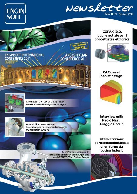
Sommario - Contents<br />
CASE STUDIES<br />
6 Multi Variate Analysis in Systematic Impeller Design Applying modeFRONTIER at Sulzer Pumps<br />
10 Analisi di un meccanismo link-drive <strong>per</strong> presse con tecnologia multibody in ANSYS<br />
13 Ottimizzazione termofluidodinamica di un forno da cucina Indesit<br />
15 Combined 1D & 3D CFD Approach for GT Ventilation System Analysis<br />
19 ANSYS WB and a Review of the Design Metrics in Piaggio: the Case of the Motor Shaft<br />
INTERVIEWS<br />
21 <strong>EnginSoft</strong> Interviews Ing. Paolo Nesti, Piaggio Group<br />
CASE STUDIES<br />
26 modeFRONTIER Used in the Design of Fatigue-Resistant Notches<br />
27 A Multi-Objective Optimization with Open Source Software<br />
SOFTWARE NEWS<br />
32 ANSYS 13: Il punto sui solutori <strong>per</strong> modelli di grandi dimensioni nelle simulazioni meccaniche<br />
33 La simulazione di sistema in ANSYS: Simplorer<br />
36 <strong>ICEPAK</strong> <strong>13.0</strong>: <strong>buone</strong> <strong>notizie</strong> <strong>per</strong> i <strong>progettisti</strong> <strong>elettronici</strong><br />
38 Development of the Novel Opencell<br />
IN DEPTH STUDIES<br />
41 Componenti forgiati di qualità necessitano di un approccio CAE integrato – es<strong>per</strong>ienze di simulazione di processo<br />
nel campo Energia e Nucleare<br />
TESTIMONIAL<br />
46 Landi Renzo: the global leader in the sector of components and LPG and CNG fuel systems<br />
JAPAN CAE COLUMN<br />
47 The CAD-CAM Coo<strong>per</strong>ation in Nissan Achieved by ASFALIS<br />
48 CAE-based tablet design<br />
52 Tokyo a Metropolis<br />
The <strong>EnginSoft</strong> Newsletter editions contain references to the following<br />
products which are trademarks or registered trademarks of their respective<br />
owners:<br />
ANSYS, ANSYS Workbench, AUTODYN, CFX, FLUENT and any and all<br />
ANSYS, Inc. brand, product, service and feature names, logos and slogans are<br />
registered trademarks or trademarks of ANSYS, Inc. or its subsidiaries in the<br />
United States or other countries. [ICEM CFD is a trademark used by ANSYS,<br />
Inc. under license]. (www.ANSYS.com)<br />
modeFRONTIER is a trademark of ESTECO srl (www.esteco.com)<br />
Flowmaster is a registered trademark of The Flowmaster Group BV in the<br />
USA and Korea. (www.flowmaster.com)<br />
MAGMASOFT is a trademark of MAGMA GmbH. (www.magmasoft.com)<br />
ESAComp is a trademark of Componeering Inc.<br />
(www.componeering.com)<br />
Forge and Coldform are trademarks of Transvalor S.A.<br />
(www.transvalor.com)<br />
AdvantEdge is a trademark of Third Wave Systems .<br />
(www.thirdwavesys.com)<br />
LS-DYNA is a trademark of Livermore Software Technology Corporation.<br />
(www.lstc.com)<br />
SCULPTOR is a trademark of Optimal Solutions Software, LLC<br />
(www.optimalsolutions.us)<br />
Grapheur is a product of Reactive Search SrL, a partner of <strong>EnginSoft</strong><br />
For more information, please contact the Editorial Team
PRESS RELEASE<br />
54 President Obama Honors <strong>EnginSoft</strong>’s Partner with the<br />
Presidential Early Career Award for Scientists and<br />
Engineers<br />
56 Formazione a distanza sugli elementi finiti<br />
BOOK REVIEWS<br />
57 REACTIVE BUSINESS INTELLIGENCE: From Data to<br />
Models to Insight<br />
EVENTS<br />
58 <strong>EnginSoft</strong> at the Optimization Day: Research and<br />
Applications<br />
60 NAFEMS World Congress 2011 - Preliminary Agenda<br />
Announced<br />
61 <strong>EnginSoft</strong> alla Fiera Made in Steel di Brescia<br />
62 <strong>EnginSoft</strong> Event Calendar<br />
PAGE 6 MULTI VARIATE ANALYSIS IN<br />
SYSTEMATIC IMPELLER DESIGN APPLYING<br />
MODEFRONTIER AT SULZER PUMPS<br />
PAGE 15 COMBINED 1D & 3D CFD<br />
APPROACH FOR GT VENTILATION<br />
SYSTEM ANALYSIS<br />
PAGE 36 <strong>ICEPAK</strong> <strong>13.0</strong>: BUONE NOTIZIE<br />
PER I PROGETTISTI ELETTRONICI<br />
Newsletter <strong>EnginSoft</strong><br />
Year 8 n°1 - Spring 2011<br />
To receive a free copy of the next <strong>EnginSoft</strong><br />
Newsletters, please contact our Marketing office at:<br />
newsletter@enginsoft.it<br />
All pictures are protected by copyright. Any reproduction<br />
of these pictures in any media and by any means is<br />
forbidden unless written authorization by <strong>EnginSoft</strong> has<br />
been obtained beforehand.<br />
©Copyright <strong>EnginSoft</strong> Newsletter.<br />
Advertisement<br />
For advertising opportunities, please contact our<br />
Marketing office at: newsletter@enginsoft.it<br />
<strong>EnginSoft</strong> S.p.A.<br />
24124 BERGAMO Via Galimberti, 8/D<br />
Tel. +39 035 368711 • Fax +39 0461 979215<br />
50127 FIRENZE Via Panciatichi, 40<br />
Tel. +39 055 4376113 • Fax +39 0461 979216<br />
35129 PADOVA Via Giambellino, 7<br />
Tel. +39 49 7705311 • Fax 39 0461 979217<br />
72023 MESAGNE (BRINDISI) Via A. Murri, 2 - Z.I.<br />
Tel. +39 0831 730194 • Fax +39 0461 979224<br />
38123 TRENTO fraz. Mattarello - via della Stazione, 27<br />
Tel. +39 0461 915391 • Fax +39 0461 979201<br />
www.enginsoft.it - www.enginsoft.com<br />
e-mail: info@enginsoft.it<br />
COMPANY INTERESTS<br />
ESTECO srl<br />
34016 TRIESTE Area Science Park • Padriciano 99<br />
Tel. +39 040 3755548 • Fax +39 040 3755549<br />
www.esteco.com<br />
CONSORZIO TCN<br />
38123 TRENTO Via della Stazione, 27 - fraz. Mattarello<br />
Tel. +39 0461 915391 • Fax +39 0461 979201<br />
www.consorziotcn.it<br />
<strong>EnginSoft</strong> GmbH - Germany<br />
<strong>EnginSoft</strong> UK - United Kingdom<br />
<strong>EnginSoft</strong> France - France<br />
<strong>EnginSoft</strong> Nordic - Sweden<br />
A<strong>per</strong>io Tecnologia en Ingenieria - Spain<br />
www.enginsoft.com<br />
ASSOCIATION INTERESTS<br />
NAFEMS International<br />
www.nafems.it<br />
www.nafems.org<br />
TechNet Alliance<br />
www.technet-alliance.com<br />
RESPONSIBLE DIRECTOR<br />
Stefano Odorizzi - newsletter@enginsoft.it<br />
PRINTING<br />
Grafiche Dal Piaz - Trento<br />
Newsletter <strong>EnginSoft</strong> Year 8 n°1 - 5<br />
The <strong>EnginSoft</strong> NEWSLETTER is a quarterly<br />
magazine published by <strong>EnginSoft</strong> SpA<br />
Autorizzazione del Tribunale di Trento n° 1353 RS di data 2/4/2008
6 - Newsletter <strong>EnginSoft</strong> Year 8 n°1<br />
Multi Variate Analysis in<br />
Systematic Impeller Design Applying<br />
modeFRONTIER at Sulzer Pumps<br />
The most important pump component - its heart - is the<br />
impeller which transforms kinetic energy into pressure and<br />
therefore generates the required head. The impeller<br />
geometry is defined by more than 50 parameters requiring<br />
ex<strong>per</strong>ienced hydraulic design engineers. Even if only 20 of<br />
these parameters have a major influence, it is obvious<br />
that a severe variation yields an excessive database which<br />
should be made use of.<br />
Fig. 1 - Two stage pump with detailed view of the first stage impeller.<br />
Fig. 2 - Dimensions of the impeller.<br />
A pro<strong>per</strong> classification of the available designs in the<br />
database gives the develo<strong>per</strong> a better understanding of<br />
the complex parameter correlation and enables the<br />
prediction of not yet available impellers by interpolating<br />
among the existing designs. This gives a first parameter<br />
estimate for the new impeller and pro<strong>per</strong>ly conditions the<br />
variable ranges for an optimization which is likely to<br />
follow. This article presents an approach based on<br />
classification of existing impeller designs with Multi<br />
Variate Analysis through Self Organizing Maps (SOM) by<br />
use of modeFRONTIER.<br />
Systematic impeller design<br />
The parameters defining an impeller include the main<br />
dimensions like outer diameter D2 and shaft diameter D0 as<br />
also the meridional contour and blade shape (Figure 2).<br />
The impeller design is done for a specified o<strong>per</strong>ating point<br />
with given flow rate Q and head H for a certain rotational<br />
speed n. Efficiency η is one criterion for an optimal<br />
impeller design not only at best efficiency point bep but<br />
also over a certain o<strong>per</strong>ating range (Figure 3, left).<br />
Suction capability, which is the pressure available at pump<br />
inlet NPSH, is another criterion (Figure 3, centre).<br />
Decreasing NPSH affects the pump head which needs to be<br />
considered.<br />
Good suction capability and high efficiency both over a<br />
broad o<strong>per</strong>ating range are conflictive design goals.<br />
Increasing suction capability at maximum o<strong>per</strong>ating point<br />
reduces efficiency at minimum o<strong>per</strong>ating point. This is an<br />
important fact when using optimization techniques in<br />
impeller design.<br />
Characteristic numbers<br />
Impellers can be classified by characteristic numbers<br />
enabling a comparison among the designs. The specific<br />
speed nq defines the form of the impeller (Figure 4) and is<br />
calculated from flow rate Q, head H and the rotational<br />
speed n. Figure 5 lists the main design parameters and<br />
shows their conversion into characteristic numbers. The<br />
outer diameter D2 of the impeller is selected according an<br />
Fig. 3 - left: Efficiency η; centre: suction capability NPSH within the o<strong>per</strong>ating range of the impeller dependent on the flow rate Q; right: NPSH3% criterion
optimal head coefficient Ψ for the specific speed nq. The<br />
inlet diameter D1 influences the suction capability and<br />
depends on the flow coefficient at inlet ϕ1. The suction<br />
capability can either be expressed by a characteristic<br />
number σ or the suction specific speed nss which both<br />
depend on the suction head at pump inlet NPSH. Similar<br />
relations exist for other dimensions.<br />
Using these characteristic numbers and dimensionless<br />
values, impellers with different outer diameters D2 can be<br />
Fig. 4 - Impeller form in meridional view dependent on specific speed nq<br />
compared and new designs can be calculated based on<br />
these values. This facilitates a classification of the<br />
impellers and the use of the SOM technique.<br />
Self-Organizing Map<br />
Any existing impeller design is described through a multidimensional<br />
vector, where each component represents a<br />
defining parameter (input) or a <strong>per</strong>formance index<br />
(output).<br />
The Self-Organizing Map (SOM) is an unsu<strong>per</strong>vised Neural<br />
Network algorithm capable to group and classify such<br />
already available impeller designs in a two-dimensional<br />
grid space. Each node of this grid is called “Unit” and it<br />
groups (includes) vectors (impeller designs)<br />
that are similar with respect to all their<br />
parameters (inputs and outputs)<br />
simultaneously.<br />
SOM preserves the topology of the data, so<br />
that similar data items will be mapped to<br />
nearby units on the map. To do so, units are<br />
hexagonal-shaped, and hence each unit has 6<br />
neighbors and is labeled by a “prototype<br />
vector” that in fact represents all the vectors<br />
included in the unit itself, as a kind of<br />
average.<br />
SOM lives in the multi-dimensional data<br />
space, but its visualization capabilities are<br />
built on the top of its representation in the<br />
grid space. Each of the hexagons becomes a<br />
Fig. 5 - Correlation between dimensional and non dimensional values<br />
Newsletter <strong>EnginSoft</strong> Year 8 n°1 - 7<br />
“pixel” being colored to reflect different pro<strong>per</strong>ties of the<br />
input data, e.g. specific speed n q, impeller width B2 or<br />
efficiency η. This way SOM overcomes the problem of<br />
visualizing multivariate data: input data are projected<br />
onto a 2D grid (Figure 6).<br />
Another advantage of the SOM is related to its intrinsic<br />
interpolation capability. There might exist regions of<br />
unexplored zones, the <strong>per</strong>formance of the impeller is not<br />
yet predicted by CFD. This is reflected in SOMs by empty<br />
hexagons separating others that are filled up by different<br />
families of designs. When this happens, it is reasonable to<br />
look at the prototype vector of the empty unit as kind of<br />
forecast of a design family that have still to be realized,<br />
and that represent a reasonable interpolation of the ones<br />
that are available. The benefit of the SOM is that, apart<br />
from the input variables characterizing such design<br />
families, also a complete forecast of the <strong>per</strong>formances is<br />
immediately available. This predictive use of the SOM is<br />
really powerful when handling designs that are described<br />
by a high number of parameters (inputs and outputs) so<br />
that any other interpolations approach, like Response<br />
Surface Modeling, becomes heavy to implement.<br />
For the pump impellers described here, a unique SOM is<br />
trained on the existing database and used to forecast new<br />
design families able to provide certain <strong>per</strong>formances.<br />
Impeller design and multi variate analysis<br />
The dimensionless values for the main parameters and the<br />
design objectives efficiency and suction capability (η,<br />
nSS,bep, nSS,max) are selected as input for the training<br />
(classification) of the SOM. Within this test case, the<br />
results of six different impeller optimizations with three<br />
Fig. 6 - Left: SOM is the blue network that adapts to real data (red points) in a X-Y-Z space,<br />
note that some nodes are far from any real point, hence the related unit will be empty.<br />
Centre: the same SOM in its 2D conventional representation: each of the nodes is a hexagonal<br />
unit. Right: each unit is colored with respect to the X-value of its prototype vector, and the<br />
square on its center represents the number of real design enclosed in the unit (see the empty<br />
units).
8 - Newsletter <strong>EnginSoft</strong> Year 8 n°1<br />
Fig. 7 - Specific speed (nq) in the SOM with distribution of existing<br />
designs<br />
different specific speeds between nq13 and nq60 are used<br />
as data basis. Goal of this study is to develop new<br />
impellers in this range with high suction capability and<br />
high efficiency for four different specific speeds (n q16,<br />
n q24, n q30, n q47) under the assumption that for each n q<br />
both o<strong>per</strong>ating point and impeller diameter D 2 are given<br />
and the shaft diameter is pre-defined from mechanical<br />
calculations.<br />
Figure 7 illustrates the trained SOM of the specific speed<br />
ranging from n q13 (blue) to n q60 (red). The squares<br />
describe the density of input parameters available. The<br />
larger the square the more data exists, no square signifies<br />
that parameter values are based on pure interpolation.<br />
The selection of the new impellers is undertaken in<br />
regions with purely interpolated data (Figure 8). For each<br />
new impeller, existing designs with a similar n q in the SOM<br />
table are compared. This is necessary as three objectives<br />
need to be fulfilled, and the SOM designs might only<br />
achieve one.<br />
The advantage of this technique is the access to every<br />
single parameter defining the impeller geometry. With an<br />
amount of over 50 parameters, the entire meridional<br />
impeller contour and the blade shape are approximated by<br />
the SOM. This method allows a complete impeller design<br />
within a few minutes just by giving the o<strong>per</strong>ating point<br />
and selecting an appropriate outer diameter D 2. The<br />
impeller parameters are taken from the SOM and converted<br />
Table 1 - Comparison of coefficients of obtained and predicted objectives for the<br />
selected designs<br />
Fig. 8 - Selected designs in the SOM (Color: specific<br />
speed)<br />
back from dimensionless<br />
to dimensional<br />
parameters. A new<br />
impeller is then generated<br />
with the conventional<br />
design tools and its<br />
<strong>per</strong>formance is checked by<br />
CFD.<br />
Table 1 shows a<br />
comparison of the<br />
<strong>per</strong>formances obtained by<br />
CFD and predicted by SOM<br />
for the selected nq. A<br />
coefficient is defined<br />
with:<br />
objectiveCFD / objective SOM ,<br />
describing the ratio of the CFD result to the prediction of<br />
the objective by the SOM. A value equal to one signifies<br />
an error of zero; the CFD <strong>per</strong>formance matches the<br />
predicted one. For a coefficient smaller than one, the<br />
<strong>per</strong>formance is over predicted, if it is larger than one, the<br />
design is under predicted by the SOM.<br />
n q24<br />
The first impeller modeled with the SOM is n q24. Therefore<br />
the best possible solution in compliance with the specific<br />
speed and the design goals is selected. CFD calculations<br />
are <strong>per</strong>formed according the CFD in the optimization<br />
process. The results are excellent, both efficiency and<br />
suction <strong>per</strong>formance are better than predicted by the SOM.<br />
n q16<br />
For the second impeller (n q16) two different designs are<br />
selected from the SOM table, one with high efficiency<br />
predicted and a second with a lower efficiency but a<br />
better expected suction capability. The impeller with high<br />
efficiency reaches almost the suction capability at bep<br />
while the impeller with the lower efficiency exceeds the<br />
suction capability. Both impellers out<strong>per</strong>form the<br />
expected suction capability at the maximum o<strong>per</strong>ating<br />
point efficiency.<br />
n q30<br />
For the impeller n q30 two different interpolated designs<br />
are selected from the SOM table, differing in suction<br />
capability at maximum o<strong>per</strong>ating point. After<br />
calculating <strong>per</strong>formances of the interpolated designs,<br />
the aspired suction capability at overload is not<br />
achieved, the other targets are out<strong>per</strong>formed. For this<br />
reason two more designs from the SOM table are<br />
selected, now with lower efficiency than the previous<br />
designs. With the lower efficiency target, the suction<br />
capability is reached for both o<strong>per</strong>ating points. This<br />
proves the conflicting design targets efficiency and<br />
suction capability.
Fig. 9 - Efficiency (red = high, blue = low) Fig. 10 - suction capability at bep (based on σ,<br />
blue = good, red=bad)<br />
n q47<br />
Two designs from the SOM table are selected. The second<br />
design with the higher suction capability target at bep<br />
misses the required suction capability at maximum<br />
o<strong>per</strong>ating point. Even if the first design does not fulfill<br />
the requirements at bep, the deviation from the target<br />
value is only small.<br />
Summary for all designs<br />
For all designs, the calculated efficiency is higher than<br />
SOM predicted. The suction capability misses the<br />
requirements for some designs because of contradicting<br />
objectives. In these cases it is possible to select new<br />
designs from the SOM with compromises in efficiency but<br />
achieving the required suction capability.<br />
Figures 9-11 present the objectives efficiency, suction<br />
capability at bep and max OP. It can be clearly seen that<br />
efficiency and suction <strong>per</strong>formance pattern are completely<br />
different. This discrepancy makes it difficult to fulfill all<br />
three objectives and either a compromise is required or<br />
one objective has to be prioritized.<br />
Conclusions<br />
The article describes a novel methodology to design<br />
impellers starting from the well assessed knowledge at<br />
Sulzer Pumps<br />
Sulzer Pumps is one of the world's leading centrifugal<br />
pump manufacturers. Intensive research and development<br />
in fluid dynamics, process-oriented products and special<br />
materials as well as reliable service helps Sulzer Pumps<br />
maintain its leading positions in its key markets. Its<br />
customers come from the oil and gas, hydrocarbon<br />
processing, power generation and pulp and pa<strong>per</strong> sectors<br />
as well as from water distribution and treatment and<br />
other general industries. The products are internationally<br />
reputed for their technical excellence.<br />
www.sulzerpumps.com<br />
Newsletter <strong>EnginSoft</strong> Year 8 n°1 - 9<br />
Fig. 11 - suction capability at max OP (based on σ,<br />
blue = good, red=bad)<br />
Sulzer Pumps. The concept has proven to provide the<br />
designer a new and effective tool to speed up the design<br />
process of the pumps core part - the impeller.<br />
Self-Organizing Maps (SOM) have been trained on the<br />
already available impeller designs and corresponding<br />
<strong>per</strong>formance indicates: such a SOM embeds the so far<br />
available pump designer knowledge, and provides a<br />
complete interpolation in regions in which designs are<br />
still missing. Each input or output variable of the impeller<br />
design can be represented through a conventional twodimensional<br />
SOM map. This allows the use of SOM as an<br />
extremely powerful tool to suggest new designs in regions<br />
in which the design space has not yet been explored to<br />
forecast their <strong>per</strong>formances. In fact, the methodology<br />
allows a new and complete impeller design in some<br />
minutes, just assigning a few parameters, as the o<strong>per</strong>ating<br />
point and the outer diameter. Any new design proposed by<br />
the SOM can be validated through high-fidelity fluid<br />
dynamic simulations (CFD) and then be used as starting<br />
point for further refinements by directly linking the CFD<br />
model to a modeFRONTIER optimizer, [2].<br />
References<br />
[1] Gülich J.: "Centrifugal Pumps", Springer, 2010<br />
[2]Krüger S., Maurer W.: "How to use modeFRONTIER<br />
within the daily hydraulic design process: Sulzer<br />
Pumps’ ex<strong>per</strong>iences with automated impeller design",<br />
modeFRONTIER 2008 Users’Meeting, Trieste, 14th-15th<br />
October 2008<br />
Wolfgang Maurer, Susanne Krueger<br />
Sulzer Pumps, Winterthur, Switzerland<br />
Luca Fuligno<br />
<strong>EnginSoft</strong> SpA, Trento, Italy<br />
Francesco Linares<br />
<strong>EnginSoft</strong> GmbH, Frankfurt am Main, Germany
10 - Newsletter <strong>EnginSoft</strong> Year 8 n°1<br />
Analisi di un meccanismo link-drive <strong>per</strong><br />
presse con tecnologia multibody in<br />
ANSYS<br />
Analysis of a link drive mechanism for presses using ANSYS<br />
MBD multibody technology<br />
This pa<strong>per</strong> presents a test case in which the tool “Rigid<br />
Dynamics” of ANSYS Workbench 13 is used to investigate the<br />
kinematics and the dynamics of a link drive mechanism<br />
equipping a deep drawing press.<br />
The device is first analyzed by developing the kinematic motion<br />
equations. This step highlights the difficulty which arises when<br />
we have to manually manipulate the equations of a complex<br />
multibody system.<br />
Then, a parameterized multibody model of the link drive is built<br />
in ANSYS. This approach is much more straightforward and<br />
allows the user to understand the mechanism’s behavior in a<br />
shorter time. In addition, the software makes it possible to<br />
watch the working mechanism animation at the end of the<br />
solution.<br />
The multibody model returns information about the dynamics,<br />
which is useful for structural design purposes. Moreover, thanks<br />
to the easy parameter management in ANSYS, we can<br />
automatically investigate and compare multiple alternatives of<br />
the same mechanism.<br />
Questo articolo presenta un test case significativo nel quale attraverso<br />
una “Rigid Dynamics” di ANSYS Workbench 13 vengono<br />
efficacemente analizzate la cinematica e la dinamica di una<br />
pressa meccanica <strong>per</strong> imbutitura profonda.<br />
L’imbutitura è un processo di formatura a freddo attraverso il<br />
quale una lamiera metallica viene trasformata in un oggetto cavo,<br />
con <strong>buone</strong> caratteristiche dimensionali e di finitura. Nello<br />
schema tradizionale, l’imbutitura si realizza attraverso un pun-<br />
Fig. 1 – confronto tra pressa “Slider–Crank”e “link drive”:<br />
velocità del punzone e zona di lavoro<br />
zone che spinge la lamiera, eventualmente fissata con un premilamiera,<br />
all'interno di una matrice. Il processo è intrinsecamente<br />
delicato <strong>per</strong>ché deve indurre nel materiale elevate deformazioni<br />
plastiche, senza raggiungere la condizione di rottura.<br />
La qualità del prodotto finale è fortemente influenzata dai parametri<br />
di processo, tra i quali spicca <strong>per</strong> importanza la velocità<br />
di discesa del punzone nel tratto di corsa in cui lavora la lamiera.<br />
Idealmente, la velocità del punzone dovrebbe essere bassa, <strong>per</strong><br />
realizzare una deformazione graduale del materiale, e costante,<br />
<strong>per</strong> evitare la formazione di pieghe e striature su<strong>per</strong>ficiali.<br />
In una pressa meccanica con tradizionale schema slider crank,<br />
la riduzione della velocità del punzone è ottenibile solo aumentando<br />
il tempo ciclo, con ovvie conseguenze negative sulla<br />
produttività dell’impianto. Pertanto, se si vogliono ottenere<br />
<strong>buone</strong> <strong>per</strong>formance di processo senza penalizzare la produzione,<br />
è opportuno predisporre un meccanismo più raffinato, che<br />
consenta maggiori libertà nella gestione della velocità del punzone.<br />
Una soluzione è il meccanismo link drive illustrato, già<br />
utilizzato da alcuni produttori di presse. La Figura 1 confronta<br />
le curve di velocità del punzone <strong>per</strong> una pressa tradizionale e<br />
una pressa link Drive di pari dimensioni (con la stessa corsa<br />
massima e lo stesso tempo ciclo).<br />
La velocità di discesa del punzone, <strong>per</strong> la pressa link drive, presenta<br />
un tratto con andamento regolare a velocità quasi costante.<br />
Inoltre, grazie al maggior numero di membri, questo<br />
meccanismo è molto versatile: variando le dimensioni del meccanismo<br />
si possono ottenere diverse curve di velocità. Risulta,<br />
<strong>per</strong>tanto, evidente che il link drive presenta caratteristiche e<br />
prestazioni molto più vantaggiose dello schema tradizionale.<br />
Studio analitico del meccanismo link drive<br />
Il paragrafo precedente ha messo in luce l’importanza della velocità<br />
di discesa del punzone nella messa a punto del processo<br />
di imbutitura. Pertanto, è opportuno focalizzare l’attenzione<br />
sull’analisi cinematica del meccanismo link drive, che <strong>per</strong>mette<br />
di comprendere come il meccanismo trasformi la rotazione del<br />
motore elettrico nella traslazione a velocità variabile del punzone.<br />
Gli approcci <strong>per</strong> condurre uno studio cinematico sono diversi.<br />
Per un meccanismo relativamente semplice come il link drive,<br />
è possibile, seppure con qualche difficoltà, derivare analiticamente<br />
le equazioni del moto. Lo schema cinematico cui si farà<br />
riferimento è riportato in Figura 2.
Fig. 2 – schema cinematico della pressa link drive<br />
I vettori L1, L3, L4, L5 e L6 rappresentano i membri mobili del<br />
meccanismo, il vettore L2 rappresenta il telaio e il vettore srappresenta<br />
la posizione del punzone (misurata da un riferimento<br />
arbitrario). Lo studio analitico della cinematica inizia con la<br />
scrittura delle equazioni di chiusura in forma vettoriale:<br />
Ciascun vettore può essere formalmente descritto nella forma<br />
L= L cos (φ), dove L è la lunghezza e φ è l’angolo di inclinazione.<br />
Sostituendo nelle precedenti e manipolando opportunamente<br />
è possibile esprimere la posizione s del punzone in funzione<br />
dell’angolo φ4 di rotazione dell’eccentrico (variabile indipendente<br />
del problema). Successivamente, si ricavano <strong>per</strong> derivazione<br />
rispetto al tempo la velocità v e l’accelerazione a. In<br />
sintesi, l’analisi cinematica mediante approccio analitico restituisce<br />
tre equazioni nella forma:<br />
Queste espressioni hanno una struttura molto articolata e <strong>per</strong>tanto<br />
ne omettiamo la scrittura estesa. Si noti che i risultati<br />
dipendono dalla legge di moto assegnata al movente e dai parametri<br />
dimensionali del meccanismo.<br />
Benché l’approccio analitico consenta di <strong>per</strong>venire ai risultati<br />
cinematici in tempi accettabili, va precisato che la manipolazione<br />
di equazioni con questo livello di complessità è una o<strong>per</strong>azione<br />
alquanto delicata: se non si dispone di strumenti <strong>per</strong> la<br />
manipolazione simbolica, il rischio di errore è decisamente elevato.<br />
Newsletter <strong>EnginSoft</strong> Year 8 n°1 - 11<br />
Simulazione multibody del meccanismo link drive<br />
Una valida alternativa <strong>per</strong> studiare meccanismi in modo più veloce<br />
e con minor rischio di errore è la simulazione tramite codice<br />
multibody. ANSYS Workbench 13, attraverso il modulo<br />
“Rigid Dynamics”, consente di creare e gestire modelli<br />
multibody a corpi rigidi. L’utilizzo di questo strumento, <strong>per</strong>mette,<br />
inoltre, di integrare i risultati dell’analisi cinematica con<br />
tutte le grandezze dinamiche fondamentali <strong>per</strong> la progettazione<br />
strutturale del dispositivo.<br />
ANSYS Workbench 13 consente di gestire in modo parametrico<br />
qualsiasi modello di calcolo. Con riferimento all’analisi<br />
multibody del link drive, la parametrizzazione <strong>per</strong>mette di simulare<br />
varie alternative del meccanismo, consentendo la scelta<br />
di quella più adatta alle esigenze.<br />
Nella fase di pre-processing avviene l’assemblaggio del modello<br />
multibody. Le geometrie dei corpi possono provenire da CAD<br />
esterni oppure possono essere create direttamente all’interno<br />
di Design Modeler. Per questa applicazione abbiamo provveduto<br />
a creare integralmente la pressa ed il meccanismo, parametrizzando<br />
le grandezze di cui andremo ad analizzare gli effetti.<br />
Sono quindi state scelte e create le connessioni tra i corpi<br />
(Figura 3).<br />
I revolute joint consentono la rotazione relativa tra i membri<br />
connessi, mentre i general joint lasciano liberi i gradi di libertà<br />
scelti esplicitamente dall’utente.<br />
Per consentire la soluzione di un modello multibody a corpi rigidi,<br />
i vincoli, inseriti sottoforma di connessioni, non devono<br />
essere ridondanti. ANSYS mette a disposizione lo strumento<br />
“Redundancy Analysis” che <strong>per</strong>mette di individuare automaticamente<br />
la presenza di vincoli in eccesso e che fornisce indi-<br />
Fig. 2 – vista 3D dell’assieme e schema delle connessioni
12 - Newsletter <strong>EnginSoft</strong> Year 8 n°1<br />
Fig. 4 – modelli di pressa ottenuti tramite parametrizzazione<br />
cazione di quali modifiche si debbono apportare <strong>per</strong> rendere il<br />
modello consistente.<br />
Il meccanismo virtuale viene azionato applicando una legge di<br />
moto all’albero dell’eccentrico. ANSYS consente di assegnare a<br />
qualsiasi connessione sia leggi di moto, sia azioni dinamiche.<br />
In entrambi i casi, le funzioni sono gestibili in forma tabulata<br />
o tramite espressioni analitiche. Nel caso del meccanismo link<br />
drive, abbiamo imposto al movente una velocità di rotazione<br />
costante.<br />
L’analisi multibody comporta l’integrazione delle equazioni del<br />
moto che il software ha sviluppato automaticamente durante<br />
l’assemblaggio del modello. ANSYS dispone di due integratori,<br />
con diverse opzioni <strong>per</strong> la gestione del passo, della convergenza<br />
e della qualità della soluzione.<br />
Nella fase di post-processing ANSYS Workbench <strong>per</strong>mette di<br />
estrarre numerosi risultati dai corpi e dalle connessioni. Le<br />
grandezze disponibili <strong>per</strong> i corpi sono di natura cinematica (posizione,<br />
velocità, accelerazione), mentre <strong>per</strong> le connessioni<br />
possiamo diagrammare le grandezze cinematiche dei gradi di libertà<br />
consentiti e le reazioni vincolari dei gradi di libertà annullati<br />
dal joint.<br />
Ad esempio, su un “revolute joint” possiamo leggere angolo,<br />
velocità ed accelerazione angolare lungo l’asse di rivoluzione,<br />
e, in aggiunta, possiamo estrarre forze radiali, forze assiali e<br />
momenti trasversali che i corpi si scambiano mutuamente.<br />
Fig. 5 – confronto della velocità del punzone <strong>per</strong> i tre modelli di pressa<br />
Confronto di 3 configurazioni del meccanismo link drive<br />
A titolo di esempio, proponiamo lo studio comparativo della risposta<br />
cinematica restituita dal meccanismo link drive modificando<br />
la coordinata orizzontale della cerniera di collegamento<br />
della biella L1 al telaio (Figura 2 e Figura 4).<br />
Nello specifico, abbiamo ipotizzato di passare da un valore di<br />
1400 mm a 1100 mm, con un valore intermedio di 1250 mm.<br />
Le tre analisi sono condotte semplicemente modificando il parametro<br />
corrispondente nell’interfaccia utente. ANSYS MBD aggiorna<br />
automaticamente le geometrie e ripete la simulazione<br />
multibody.<br />
La Figura 5 illustra gli effetti del parametro scelto sulla velocità<br />
del punzone. Lo zoom mette in particolare evidenza la comparsa<br />
del tratto a velocità quasi costante, passando dalla pressa<br />
A alla pressa C. Pertanto, se l’obiettivo è quello di usare la<br />
pressa <strong>per</strong> un processo di imbutitura, la soluzione C è la migliore.<br />
Naturalmente, sfruttando la parametrizzazione del modello,<br />
è possibile individuare configurazioni con prestazioni ulteriormente<br />
migliorate.<br />
Per maggiori informazioni:<br />
Fabiano Maggio - <strong>EnginSoft</strong><br />
info@enginsoft.it<br />
L’esempio del meccanismo link drive solleva una serie di<br />
problematiche tipiche della modellazione multibody. Infatti,<br />
l’utente deve scegliere con cura numero e tipologia di vincoli<br />
se non vuole <strong>per</strong>venire a risultati incompleti o addirittura<br />
errati. L’utilizzo di strumenti come “ANSYS Transient<br />
Structurla MBD” presuppone che l’utente possieda adeguate<br />
nozioni di meccanica applicata e calcolo numerico che gli<br />
consentano di tradurre correttamente un sistema fisico in un<br />
modello virtuale. La schematizzazione può avvenire in modo<br />
più o meno raffinato, con conseguenze dirette sull’efficacia<br />
della simulazione. È compito del modellista scegliere<br />
dimensione, grado di complessità e dettagli del modello che<br />
vuole creare, considerando simultaneamente obiettivi da<br />
raggiungere, onere computazionale e tempo a disposizione.<br />
Il miglior modello non è quello più dettagliato, ma quello<br />
che risponde in modo più veloce ed esauriente alle esigenze.<br />
Questa regola, che vale in generale <strong>per</strong> tutte le dimensioni<br />
del CAE, assume un ruolo decisivo <strong>per</strong> la simulazione<br />
multibody.<br />
<strong>EnginSoft</strong> propone un corso di modellistica multibody della<br />
durata di 2 giorni a tutti i <strong>progettisti</strong> che affrontano<br />
quotidianamente problemi di cinematica e dinamica. Il corso<br />
è pensato e strutturato in modo da trasferire in breve tempo<br />
le conoscenze che servono a formulare consapevolmente le<br />
principali scelte di modellazione multibody. Il corso verrà<br />
tenuto dal prof. Roberto Lot dell’Università di Padova in<br />
collaborazione con l’ing. Fabiano Maggio di <strong>EnginSoft</strong>.<br />
Per informazioni sui contenuti consultare il sito del<br />
consorzio TCN www.consorziotcn.it<br />
Per iscrizioni e informazioni generali consultare la sig.ra<br />
Mirella Prestini della segreteria del consorzio. E-mail:<br />
info@enginsoft.it Tel: 035 368711
Indesit Company è tra i leader in<br />
Europa nella produzione e commercializzazione<br />
di grandi elettrodomestici:<br />
lavabiancheria, asciugabiancheria, lavastoviglie,<br />
frigoriferi, congelatori,<br />
cucine, cappe, piani di cottura e forni.<br />
Proprio su quest’ultimo prodotto, il<br />
forno da cucina, si è recentemente<br />
concentrata un fase di sviluppo volta a<br />
migliorarne efficienza in termini di<br />
consumi e di uniformità di cottura.<br />
Lavorando già da tempo con strumenti<br />
di modellazione numerica (nello<br />
specifico ANSYS ICEM CFD e ANSYS CFX) Fig. 1<br />
<strong>per</strong> coadiuvare le prove s<strong>per</strong>imentali,<br />
Indesit Company ha deciso di utilizzare tali strumenti <strong>per</strong> tutta<br />
la fase di ottimizzazione della termodinamica interna del forno,<br />
avvalendosi del software di ottimizzazione modeFRONTIER e della<br />
collaborazione dei tecnici della <strong>EnginSoft</strong> S.p.A.<br />
A valle di studi s<strong>per</strong>imentali e considerazioni basate su know<br />
how interno, si è pensato che, <strong>per</strong> migliorare le prestazioni del<br />
forno dal punto di vista energetico e funzionale, l’attenzione<br />
maggiore doveva essere posta sulla paratia forata che si trova tra<br />
la ventola e la zona di cottura. Il lavoro presentato, è quindi<br />
quello dell’ottimizzazione geometrica di tale paratia, alla ricerca<br />
della configurazione tale da avere minori consumi ed una maggiore<br />
uniformità di tem<strong>per</strong>atura nella muffola.<br />
Modellazione<br />
Si è partiti dalla modellazione di tutto il “volume bagnato” del<br />
forno nella configurazione baseline di partenza. Il forno, in questa<br />
configurazione, presenta anche una leccarda nella parte inferiore<br />
della zona di cottura. Sfruttando il fatto che la parte geometrica<br />
soggetta a modifica parametrica è la sola paratia, si è<br />
pensato di dividere il volume in due parti con un piano che separi<br />
il dominio di calcolo in prossimità della paratia. In questo<br />
modo, la parte di modello a valle della paratia, comprendente<br />
anche tutta la leccarda, rimane invariata, e viene <strong>per</strong>ciò preparata<br />
(geometria + griglia di calcolo) una sola volta. L’altra parte<br />
del modello, è a sua volta suddivisa in un volume che rimane invariato,<br />
il dominio rotante con la ventola, e tutto il resto, comprendente<br />
fra gli altri la paratia, la cui geometria e griglia di calcolo<br />
sono state parametrizzate <strong>per</strong> poter essere rigenerate automaticamente<br />
di volta in volta sulla base delle scelte o<strong>per</strong>ate<br />
dal’ottimizzatore.<br />
Il software utilizzato <strong>per</strong> le modifiche geometriche e la generazione<br />
della griglia di calcolo è stato ANSYS ICEM CFD.<br />
Mettendo a punto una sequenza di istruzioni opportune, ICEM<br />
modifica la geometria della paratia e genera la griglia del volume<br />
ottenuto. In questo insieme di istruzioni (script) sono<br />
presenti oltre a tutti i parametri geometrici, anche quelli re-<br />
Newsletter <strong>EnginSoft</strong> Year 8 n°1 - 13<br />
Ottimizzazione termofluidodinamica di<br />
un forno da cucina Indesit<br />
Fig. 2<br />
lativi alla dimensione degli elementi<br />
della griglia di calcolo, sia a livello<br />
globale che locale. Per tutte le configurazioni<br />
analizzate, 3 strati di prismi<br />
sono stati estrusi su tutte le pareti del<br />
dominio di calcolo. Le griglie di calcolo<br />
che tipicamente si possono ottenere<br />
con questa impostazione constano<br />
di circa due milioni di elementi tetraedrici<br />
ed un milione di prismi. È chiaro<br />
tuttavia che il numero di elementi è<br />
leggermente diverso <strong>per</strong> ogni configurazione,<br />
essendo la geometria parametricamente<br />
variata <strong>per</strong> ogni design.<br />
L’attività sul modello baseline, oltre<br />
che rappresentare il riferimento <strong>per</strong> quantificare il margine e la<br />
direzione del miglioramento nella fase di ottimizzazione, è servita<br />
anche <strong>per</strong> la fase di taratura, indispensabile in attività di<br />
questa portata <strong>per</strong> determinare il miglior compromesso tra numero<br />
di elementi, qualità degli stessi e numerica più efficace all’ottenimento<br />
di risultati affidabili del calcolo CFD.<br />
Variabili di Input ed Output<br />
modeFRONTIER è un ottimizzatore multi disciplinare e multi<br />
obiettivo. L’es<strong>per</strong>ienza che vanta <strong>EnginSoft</strong> nell’utilizzo di questo<br />
strumento accoppiato a software di analisi numerica, ha consentito<br />
la messa a punto di un flusso logico di macro-o<strong>per</strong>azioni<br />
che hanno portato ad una vera e propria “customizzazione”<br />
<strong>per</strong> il problema qui illustrato (ottimizzazione forno).<br />
I parametri geometrici di ingresso sono stati in tutto sedici. Essi<br />
hanno <strong>per</strong>messo di controllare dimensione, distribuzione e numero<br />
di fori sui quattro bordi della paratia. Lo spazio delle possibili<br />
configurazioni è stato delimitato in tre modi: dai valori minimi<br />
e massimi che ciascuna variabile di input doveva rispettare,<br />
da vincoli di costruzione, e da vincoli geometrici che evitassero<br />
geometrie degeneri.<br />
Discorso un po’ più dettagliato meritano le variabili di output. A<br />
monte del lavoro di ottimizzazione è stata valutata molto attentamente<br />
la modellazione delle variabili in uscita. Esse infatti devono<br />
rappresentare un indice sia dell’efficienza del forno in termini<br />
di uniformità della tem<strong>per</strong>atura che del suo consumo di
14 - Newsletter <strong>EnginSoft</strong> Year 8 n°1<br />
energia. Si è deciso di scegliere<br />
come grandezza <strong>per</strong> l’uniformità<br />
di tem<strong>per</strong>atura, il suo scarto quadratico<br />
medio (RMS di T) misurato<br />
su una nuvola di punti situata<br />
“ad hoc” nella zona di cottura,<br />
mentre <strong>per</strong> la potenza elettrica<br />
necessaria si è optato <strong>per</strong> la portata<br />
d’aria ricircolante all’interno<br />
della muffola. Con queste assunzioni,<br />
gli obiettivi implementati<br />
in modeFRONTIER diventano <strong>per</strong>ciò<br />
la ricerca di un design che<br />
renda minimo il valore dello scarto<br />
quadratico medio delle tem<strong>per</strong>ature<br />
sulla nuvola di punti garantendo<br />
allo stesso tempo una<br />
portata d’aria su<strong>per</strong>iore ad un va- Fig. 3<br />
lore limite precedentemente stabilito come limite inferiore.<br />
Il processo logico che lega tutti i passaggi è il seguente:<br />
Partendo dal file replay.rpl che modeFRONTIER ha aggiornato<br />
con i valori delle variabili di ingresso, lo script, eseguito<br />
in batch da ICEM, si occupa di modificare la paratia con i<br />
fori, copiare il resto della geometria che resta immutata e<br />
generare la griglia di calcolo.<br />
Terminata questa prima fase, la griglia di calcolo generata<br />
viene caricata assieme a quella che resta inalterata nel preprocessor<br />
di CFX. Al modello così aggiornato viene quindi<br />
applicato il setup fisico e numerico dell’analisi cfd, scritto il<br />
file di lancio e lanciato il run, specificando eventualmente se<br />
il calcolo deve essere eseguito in modalità parallela. Anche<br />
questa fase è interamente eseguita in modalità batch da tutti<br />
i software coinvolti.<br />
Finita l’analisi, sempre in batch, un altro script del post-processore<br />
di CFX, calcola le grandezza di output dal file di<br />
risultati, concludendo così l’iterazione <strong>per</strong> il singolo design<br />
Doe e Ottimizzazione<br />
Il DOE (Design Of Ex<strong>per</strong>iment) di partenza è stato realizzato mediante<br />
l’algoritmo RANDOM tra i più adatti <strong>per</strong> un’ottimizzazione<br />
mono-obiettivo. In effetti anche se gli output sono due, solo<br />
la minimizzazione dello scarto quadratico medio della tem<strong>per</strong>atura<br />
è un vero e proprio obiettivo, dato che il controllo del valore<br />
di portata d’aria smaltita dalla ventola sia sempre su<strong>per</strong>iore<br />
ad un valore minimo è considerato come un vincolo del problema.<br />
Il numero di design iniziale, dipendente anche dal tipo di<br />
algoritmo scelto <strong>per</strong> l’ottimizzazione, è in questo caso calcolato<br />
come la somma dei parametri di ingresso più uno, come richiesto<br />
dall’algoritmo di ottimizzazione utilizzato.<br />
A seguito della campagna di analisi sui risultati del DOE di partenza,<br />
è iniziata la fase di ottimizzazione, mediante l’utilizzo<br />
dell’SIMPLEX. Il numero di design simulati in questa fase, utili<br />
all’ottenimento di una buona convergenza dell’algoritmo stesso,<br />
è stato di 107.<br />
Ottenuto il design “ottimo”, sfruttando le potenzialità di postprocessing<br />
e statistica presenti all’interno di modeFRONTIER è<br />
stato possibile estrarre dalla considerevole<br />
mole di dati resisi disponibili, delle informazioni<br />
importanti <strong>per</strong> capire il legame tra le<br />
varibili di input e tra ciascuna di esse e<br />
l’obiettivo. Più in generale, questa fase consente<br />
di raccogliere delle preziose informazioni<br />
<strong>per</strong> capire più approfonditamente il<br />
problema studiato, soprattutto laddove esso<br />
dipenda da diversi input e output anche fra<br />
loro in forte contrasto, tipicamente con<br />
comportamento non lineare.<br />
Strumenti quali matrici di correlazione, grafici<br />
a coordinate parallele, filtri, bubble multidimensionali,<br />
hanno consentito di stabilire<br />
quale sia il peso dei singoli ingressi sui risultati,<br />
e quale sia il migliore intervallo di<br />
utilizzo tra i valori ammissibili, <strong>per</strong> ogni variabile.<br />
Infine, conoscendo come ogni variabile influisce sul risultato finale,<br />
partendo dal miglior design sono state implementate modifiche<br />
aggiuntive, che, integrando quelle previste dallo spazio<br />
parametrico sopra illustrato, hanno portato ad un ulteriore miglioramento<br />
delle <strong>per</strong>formance del forno.<br />
Dall’attività nel suo complesso, ne è scaturita una profonda conoscenza<br />
del fenomeno fisico, delle relazioni fra le variabili, con<br />
soddisfacenti riscontri s<strong>per</strong>imentali.<br />
Risultati e Conclusioni<br />
Grazie alle simulazioni numeriche e all’es<strong>per</strong>ienza dei tecnici<br />
Indesit nell’indirizzare decisioni e assunzioni da prendere, le<br />
prestazioni del forno da cucina sono migliorate nell’ordine del<br />
20% sullo scarto quadratico medio rispetto alla configurazione<br />
iniziale.<br />
Le prove s<strong>per</strong>imentali sul miglior design hanno confermato i risultati<br />
numerici ed un risparmio energetico dovuto ad una portata<br />
smaltita dalla ventola su<strong>per</strong>iore a quella del design di partenza.<br />
Fig. 3<br />
Gianluca Mattogno, Indesit - gianluca.mattogno@indesit.com<br />
Fabio Damiani, <strong>EnginSoft</strong> - info@enginsoft.it
The Gas Turbine ventilation system is designed to supply<br />
the necessary amount of air for cooling and to prevent the<br />
accumulation of hazardous gases in the enclosure by<br />
maintaining a slight over-pressure. The classical GE<br />
approach to studying ventilation system o<strong>per</strong>ating<br />
conditions consists of modeling the whole system as a<br />
series of discrete losses, where the ASHRAE duct-fitting<br />
database provides the corresponding pressure loss<br />
coefficients. The system is solved by means of a onedimensional<br />
flow simulation tool (Flowmaster).<br />
The goal of this work was to improve the critical points<br />
that affect the above-mentioned procedure, such as<br />
modeling of complex fittings and bend interactions. For<br />
this purpose, dedicated CFD analyses were <strong>per</strong>formed to<br />
characterize the loss coefficient for splitting and bend<br />
interactions at different o<strong>per</strong>ating conditions (split<br />
<strong>per</strong>centage and inlet flow rate) for two different<br />
ventilation systems. The resulting loss coefficient curves<br />
have been implemented within the corresponding onedimensional<br />
Flowmaster models. Finally, to characterize<br />
off-design conditions, a variable Heat Rejection model<br />
(obtained from previous CFD analyses) and real fan curves<br />
were used.<br />
This new approach produces more accurate results, as<br />
confirmed by the close agreement with ex<strong>per</strong>imental<br />
measurements. Among the benefits of using this new<br />
approach is the ability to characterize the flow behavior<br />
of complex fittings. This would be useful in the event of<br />
a fitting redesign or for noise reduction analyses.<br />
Current GE approach to studying<br />
Gas Turbine Ventilation Systems<br />
A ventilation system must provide a continuous source of<br />
cooling air over the entire Gas Turbine o<strong>per</strong>ation range in<br />
order to:<br />
maintain a uniform and constant airflow through the<br />
flange-to-flange Gas Turbine at all ambient conditions;<br />
remove heat and maintain the air tem<strong>per</strong>ature in the<br />
compartment below the o<strong>per</strong>ating limit. (The<br />
o<strong>per</strong>ating limit is set according to the tem<strong>per</strong>ature<br />
rating of the components located in the<br />
compartment);<br />
eliminate stagnation zones and prevent the<br />
accumulation of hazardous gases;<br />
prevent the ingress of dust and sand in gas turbines<br />
located in regions prone to sandstorm conditions by<br />
means of pro<strong>per</strong> compartment pressurization.<br />
Newsletter <strong>EnginSoft</strong> Year 8 n°1 - 15<br />
Combined 1D & 3D CFD Approach for<br />
GT Ventilation System analysis<br />
Specific Design Practices provide a general description,<br />
acceptance limits and design criteria that a ventilation<br />
system must meet for Oil & Gas applications (e.g.,<br />
enclosure design tem<strong>per</strong>ature ranges, design pressure<br />
ranges, purging ranges, etc.).<br />
As mentioned, the current GE approach to studying GT<br />
ventilation systems consists of modeling the whole system<br />
as a series of “blocks”. Each block represents a source of<br />
pressure loss (concentrated loss) due to changes in shape<br />
(e.g., elbow, transition, etc.), flow direction or the<br />
presence of physical obstacles within the system. The<br />
ASHRAE duct-fitting database provides the corresponding<br />
pressure loss coefficients.<br />
Following the net balancing by means of a onedimensional<br />
flow tool (Flowmaster), the system is<br />
characterized in terms of velocities, pressures, and flow<br />
rate split.<br />
Critical points for this approach are the modeling of<br />
complex fittings and bend interactions. In order to<br />
improve the current Ventilation System calculation<br />
procedure, dedicated CFD analyses were <strong>per</strong>formed for<br />
these critical points. A combined 1D & 3D CFD approach<br />
was adopted to study two different GE Ventilation<br />
Systems, called for simplicity System A and System B.<br />
Numerical calculations for System A<br />
The current System A Flowmaster network, modeled as a<br />
series of discrete losses, is shown in Figure 1. The<br />
Fig. 1 - System A Flowmaster model based on discrete losses.
16 - Newsletter <strong>EnginSoft</strong> Year 8 n°1<br />
enclosure is modeled as two heaters and the fan as two<br />
flow sources with a flow rate of 65000 m 3<br />
/h, estimated by<br />
using the enthalpy balance equation:<br />
were:<br />
= mass air flow [Kg/s],<br />
= enclosure heat rejection [W]<br />
= specifiwec heat at constant pressure [J/Kg °C]<br />
= maximum allowable outlet air tem<strong>per</strong>ature [°C]<br />
= max ambient tem<strong>per</strong>ature [°C]<br />
In order to develop a more suitable model (taking into<br />
account interactions, 3D characteristics of the fluid, etc.),<br />
dedicated ANSYS FLUENT CFD analyses were <strong>per</strong>formed. In<br />
particular, a critical point for the discrete losses modeling<br />
is the flow split into the Load Compartment and the Gas<br />
Turbine Compartment (see Figure 2).<br />
Fig. 2 - Analyzed split (left) and Load Compartment final section (right),<br />
System A<br />
It is useful to define the coefficients K12 and K13 as:<br />
;<br />
where:<br />
P01 = inlet total pressure<br />
P02 = GT Compartment total pressure<br />
P03 = Load Compartment total pressure<br />
V2 = GT Compartment mean velocity<br />
V3 = Load Compartment mean velocity<br />
For the characterization of the flow<br />
split at different o<strong>per</strong>ating points,<br />
two test campaigns were <strong>per</strong>formed.<br />
In both cases the inlet flow rate was<br />
fixed (65000 m 3<br />
/h and 130000 m 3<br />
/h,<br />
respectively) and, for each of these, a<br />
variable split <strong>per</strong>centage between the<br />
GT and Load compartments was used.<br />
These analyses provided K12 and K13,<br />
K12 (GT Compartment) K13 Load Compartment<br />
ASHRAE Database 0.4 0.71<br />
modified ASHRAE model<br />
(ex<strong>per</strong>ience based)<br />
1.15 1.5<br />
CFD 0.4-0.6 2.28<br />
Table 1: Loss coefficients used for standard calculations, System A.<br />
defined in (2), as a function of the flow rate split (see<br />
Figure 3).<br />
Subsequently, these coefficients were implemented within<br />
the corresponding one-dimensional Flowmaster model.<br />
A comparison between the loss coefficients obtained<br />
using CFD and those coefficients used for standard<br />
calculations is summarized in Table 1.<br />
Finally, to better simulate the ventilation system a bend<br />
interaction analysis was <strong>per</strong>formed on the Load<br />
Compartment final section, which is highlighted in Figure<br />
2 (for System B the geometry of this section is the same).<br />
The total loss coefficient as a function of the inlet<br />
velocity is shown in Figure 4. The loss coefficient<br />
decreases as the inlet flow velocity increases, and a good<br />
agreement with the ASHRAE database value was found for<br />
a velocity of about 5m/s. For higher velocity values the<br />
difference between the two curves (CFD and ASHRAE)<br />
starts to be significant. Again, the loss coefficient curve<br />
obtained was implemented within the new model.<br />
The fan, previously modeled as two flow sources, was<br />
replaced by the “FAN” element with the corresponding real<br />
o<strong>per</strong>ating curve.<br />
The final System A Flowmaster model including the main<br />
differences from the standard approach is shown in Figure<br />
5.<br />
The results obtained with the new model were compared<br />
with the results obtained by the ADV (Air Ducts and<br />
Ventilation) department using a model based on the<br />
ASHRAE loss coefficient with appropriate corrections<br />
based on ex<strong>per</strong>ience and with the results obtained with a<br />
pure ASHRAE model (see Table 2). The reliability of each<br />
approach was evaluated through comparison with<br />
ex<strong>per</strong>imental data.<br />
Fig. 3 - K12 and K13 as a function of flow rate split for two different inlet flow rates, System A.
Fig. 4 - Loss coefficient curve for Bend Interaction.<br />
Fig. 5 - New System A Flowmaster model.<br />
Table 2 summarizes the results obtained for the enclosure<br />
pressure. Using the new approach we got a favorable level<br />
of approximation with respect to the measured value<br />
(error equal to 7%). The other two approaches yielded<br />
errors higher than 25%.<br />
Figure 6 shows for each model the load compartment<br />
velocity and the corresponding error from the measured<br />
value at clean filter house conditions. The measured mean<br />
velocity is 12.47 m/s.<br />
Both the new model and the modified ASHRAE model<br />
(ex<strong>per</strong>ience-based) led to a high level of agreement (error<br />
Discrete loss model<br />
(ASHRAE)<br />
Discrete loss model<br />
(Ex<strong>per</strong>ience based)<br />
New model<br />
(Flowmaster+CFD)<br />
Enclosure<br />
Pressure[mmH2O]<br />
Measured<br />
value[mmH2O]<br />
Error[%]<br />
54.40 43.0 26.5<br />
54.86 43.0 27.6<br />
40.00 43.0 -7.0<br />
Table 2: Enclosure pressure, clean filter house conditions, System A.<br />
Newsletter <strong>EnginSoft</strong> Year 8 n°1 - 17<br />
lower than 5%). On the contrary, the pure ASHRAE model<br />
produced an error of 18%.<br />
Numerical calculations for System B<br />
Also for the System B split, several tests were <strong>per</strong>formed<br />
to determine the split loss coefficients for different<br />
o<strong>per</strong>ating conditions. Figure 7 shows K12 and K13 as a<br />
function of the split flow rate <strong>per</strong>centage between the GT<br />
and Load compartments for an inlet flow rate equal to<br />
70000 m 3<br />
/h (design flow rate). As one can see, both<br />
curves follow a linear trend.<br />
Similar to the System A model, the new<br />
System B Flowmaster model contains the<br />
loss coefficient curves obtained from CFD<br />
analyses (including the bend interaction<br />
curve) and the real fan o<strong>per</strong>ating curve.<br />
Finally, in order to better simulate the<br />
heat removal, the heat rejection was<br />
modeled as a function of the mass flow<br />
rate, in accordance with recent studies<br />
<strong>per</strong>formed by the SYS-OPT (System<br />
Optimization) department, that is:<br />
where:<br />
HR = heat rejection<br />
HR0 = reference heat rejection<br />
= mass flow rate<br />
0 = reference mass flow rate<br />
n = reference exponent<br />
The final System B Flowmaster model is shown in Figure 8.<br />
Figure 9 shows the GT and Load Compartment velocity<br />
obtained with the STD model (previous calculations) and<br />
the new model for dirty and clean filter house conditions.<br />
Fig. 6 - Load compartment velocity, clean filter house conditions, System A.
18 - Newsletter <strong>EnginSoft</strong> Year 8 n°1<br />
In both cases, the load<br />
compartment velocity obtained<br />
with the new approach is<br />
significantly higher than the old<br />
value (+49%). In particular, for<br />
the new approach, we got a split<br />
of 89-11% compared to a value of<br />
92.7-7.3% obtained from<br />
previous calculations.<br />
Considering that the target flow<br />
rate is 90-10%, the new approach<br />
again provides more accurate<br />
results.<br />
No significant variations between<br />
the two approaches in terms of<br />
enclosure pressure and<br />
tem<strong>per</strong>ature were found.<br />
Fig. 7 - K12 and K12 as a function of flow rate split, System B.<br />
Conclusions<br />
In this work, a combined 1D and<br />
3D numerical approach was<br />
adopted to study two GE<br />
ventilation systems. This<br />
approach, compared to the<br />
current one-dimensional<br />
approach, improves the<br />
simulation of the actual o<strong>per</strong>ating<br />
conditions in terms of inlet flow<br />
rate, duct velocity and enclosure<br />
pressure, as confirmed by the<br />
close agreement with ex<strong>per</strong>imental<br />
measurements.<br />
Among the benefits of using this new approach is the<br />
ability to characterize the flow behavior of complex<br />
fittings. This would be useful to support the redesign of<br />
fittings or for noise reduction analyses.<br />
Fig. 8 - New System B Flowmaster model.<br />
About GE Oil & Gas<br />
GE Oil & Gas (www.ge.com/oilandgas) is a world leader<br />
in advanced technology equipment and services for all<br />
segments of the oil and gas industry, from drilling and<br />
production, LNG, pipelines and storage, to industrial<br />
power generation, refining and petrochemicals. We<br />
also provide pipeline integrity solutions, including<br />
inspection and data management, and design and<br />
manufacture wire-line and drilling measurement<br />
solutions for the oilfield services segment. As part of<br />
our 'Innovation Now' customer focus and commitment,<br />
GE Oil & Gas exploits technological innovation from<br />
other GE businesses, such as Aviation and Healthcare,<br />
to continuously improve oil and gas industry<br />
<strong>per</strong>formance and productivity. GE Oil & Gas employs<br />
more than 12,000 people worldwide and o<strong>per</strong>ates in<br />
over 100 countries.<br />
References<br />
[1]Miller, D.S.: Internal Flow Systems; 2nd Edition, Miller<br />
Innovations, 2008<br />
[2]Idelchik I.E.: Handbook of hydraulic resistance, 3rd<br />
Edition, CRC Begell House, 1994<br />
[3]ASHRAE Duct Fitting Database, Version 2.5.0. ASHRAE<br />
L. Barbato, M. Blarasin, S. Rossin<br />
GE Oil & Gas,<br />
Via Felice Matteucci 2, Florence, Italy<br />
Figure 9 - GT and Load compartment velocity for STD and New approach,<br />
System B.
I still can remember the time when, looking at a 3D CAD<br />
model of an engine block, I would start thinking about the<br />
best way to translate it into a PREP7 procedure. I would<br />
come up with something to mesh, but the next time I<br />
would have to start from scratch again. In those times,<br />
beam representations in conjunction with SIFs were the<br />
best way to go with crankshafts. Other components<br />
required similar efforts.<br />
Things evolved in a continuous fashion, but a<br />
discontinuity came when ANSYS changed its face<br />
completely with Workbench. At first I thought that<br />
dealing with it would have been a dive into a bottomless<br />
ocean, just like the first time I met a CONTA174. But I’ve<br />
always been a fundamentalist when it comes to new CAE<br />
techniques, so I tried to move to WB as quickly as I could<br />
and to the maximum possible extent.<br />
And my way of working radically changed: geometry<br />
import and meshing issues sharply decreased, and past<br />
Newsletter <strong>EnginSoft</strong> Year 8 n°1 - 19<br />
ANSYS WB and a review of the design<br />
metrics in Piaggio: the case of the<br />
motor shaft<br />
models could be used as templates for new, similar<br />
analyses. This last aspect evolved dramatically with the<br />
introduction of WB projects, where bunches of<br />
interconnected analyses form now real CAE procedures,<br />
laid down with nearly no effort.<br />
Such a case happened just a few weeks ago when I came<br />
up against a crankshaft simulation.<br />
I had to use WB both as stand-alone application and as<br />
part of a CAE chain, including MBS and durability<br />
analyses.<br />
The simulations I had to <strong>per</strong>form required both linear and<br />
nonlinear models, involving the simulation of neighboring<br />
components, in addition to the crankshaft pro<strong>per</strong>. WB<br />
allowed me to quickly setup a baseline model: DM fixed a<br />
few CAD issues and Mechanical Automatic Contact<br />
detection feature greatly speeded up the assembly setup.<br />
The CAD interface can sense CAD simplified<br />
representations, allowing to <strong>per</strong>form partial CAD imports,<br />
really useful when dealing with big CAD models.<br />
Generating all the other models I needed from the<br />
baseline one was really easy at a project level, duplicating<br />
when a different topology was needed and linking when<br />
only different load systems or different analysis types<br />
were required.<br />
That way, I could assess both the frictional load transfer<br />
capability and the fatigue <strong>per</strong>formance of the crankshaft<br />
assembly.<br />
For the former I used nonlinear models, exploiting the WB<br />
contact features, whose default settings are much more<br />
error-proof than navigating among all the keyoptions and
20 - Newsletter <strong>EnginSoft</strong> Year 8 n°1<br />
real constants of the good old CONTA family. I could check<br />
the functionality of friction couplings with both standard<br />
and custom postprocessing quantities. The latter are<br />
easily definable with the aid of another WB feature: the<br />
Worksheets.<br />
With them you have an overview of your modeling stages<br />
in a neat tabular form. You can check the pro<strong>per</strong>ties of the<br />
bodies included in an assembly, of the contact interfaces,<br />
or the available postprocessing quantities, to name a few.<br />
From a table you can jump to the relevant model element<br />
with a simple click. So Worksheets prove to be a nice tool<br />
to check what you’ve done.<br />
The fatigue analyses required the computation of<br />
load/stress transfer functions and of a Craig-Bampton<br />
modal representation [1]. The latter was calculated by<br />
means of a simple combination of rigid Remote<br />
Displacement features and of a Commands object: no more<br />
messing around with CERIGs, since WB did the job totally<br />
in the background.<br />
The results of the activity were not only fatigue safety<br />
factors and stress distributions; besides them, and above<br />
all, a neat trace of what I did has been left both at a<br />
Project and System level, in the WB jargon. The next time<br />
a similar component will have to be simulated, it will be<br />
an update process, not a generation one. Opening the WB<br />
project, the modeling procedure will be easily<br />
recognizable.<br />
In the past the CAE techniques had a hard time trying to<br />
be simultaneously fast and accurate; that slowed their<br />
integration into the development process of complex<br />
systems. I think that WB has been one of the major<br />
milestones in overcoming these problems, therefore<br />
allowing the simulations to be <strong>per</strong>ceived as standard and<br />
required activities.<br />
For more information:<br />
Roberto Gonella - <strong>EnginSoft</strong><br />
info@enginsoft.it<br />
[1]R.R. Craig, M.C.C. Bampton - Coupling of substructures<br />
for dynamic analyses - AIAA Journal,vol. 6, n.7, 1968
<strong>EnginSoft</strong><br />
interviews Ing.<br />
Paolo Nesti,<br />
Piaggio Group<br />
ABOUT THE PIAGGIO GROUP<br />
The Piaggio Group was founded in 1884 and nowadays<br />
is the European leader and one of the<br />
major players worldwide in the sector of twowheeler<br />
vehicles. The Group is also a global leader<br />
in the development and manufacture of<br />
commercial vehicles. The product range of the<br />
Piaggio Group includes scooters, motorbikes and<br />
motorcycles from 50 to 1,200 cc and the trademarks:<br />
Piaggio, Vespa, Gilera, Aprilia, Moto<br />
Guzzi, Derbi, Scarabeo. In the light commercial<br />
vehicle market, Piaggio is represented with its<br />
three- and four-wheeler vehicles and the trademarks: Ape,<br />
Porter and Quargo.<br />
The Group’s head office is based in Pontedera (in the province<br />
of Pisa, Italy). Since 2003, it is managed by the industrial<br />
holding Immsi S.p.A. Roberto Colaninno is the President and<br />
Managing Director of the Piaggio Group.<br />
The manufacturing plants are located in: Pontedera (Pisa),<br />
Noale and Scorzè (Venice), Mandello del Lario (Lecco),<br />
Martorelles (Barcelona, Spain), Baramati (India, in the<br />
Maharashtra nation), and Vinh Phuc (Vietnam).<br />
Furthermore, there is a joint venture in China (in Foshan, in<br />
the province of Guangdong). In 2009, the Piaggio Group sold<br />
607.700 vehicles worldwide: 410,300 two-wheeler vehicles<br />
and 197.400 commercial vehicles. Motorcycle racing is a very<br />
important business for the Piaggio Group. Some Piaggio<br />
models are well known for some world records: 95 world<br />
championships won in different fields and more than 500 victories<br />
in different competitions. Among the most successful<br />
brands is Aprilia. With its 45 global qualifications and 278<br />
wins in the GP, Aprilia is the most successful brand in the history<br />
of the GP Motorcycle Racing in Italy and Europe.<br />
The engineer Paolo Nesti graduated in Mechanical<br />
Engineering. Since 1988, the focus of his work has been on<br />
engines. Presently he is responsible for the design of engines<br />
and for computational systems at the Centro Tecnico<br />
Motori 2 Ruote of Pontedera. This Piaggio Group Center is<br />
dedicated to the development of two-wheeler vehicle power<br />
engines.<br />
1. What is or should be the role of innovation in the<br />
industrial and entrepreneurial world?<br />
Nowdays the market has enlarged itself and Global<br />
competition is our new work environment and we are not<br />
Newsletter <strong>EnginSoft</strong> Year 8 n°1 - 21<br />
<strong>EnginSoft</strong><br />
intervista l’ing.<br />
Paolo Nesti del<br />
Gruppo Piaggio<br />
IL GRUPPO PIAGGIO: PROFILO<br />
Il Gruppo Piaggio, fondato nel 1884, è il più<br />
grande costruttore europeo e uno dei principali<br />
player mondiali nel settore dei veicoli motorizzati<br />
a due ruote. È inoltre protagonista internazionale<br />
nel settore dei veicoli commerciali.<br />
La gamma di prodotti del Gruppo comprende<br />
scooter, moto e ciclomotori da 50 a 1.200cc<br />
con i marchi Piaggio, Vespa, Gilera, Aprilia,<br />
Moto Guzzi, Derbi, Scarabeo, e veicoli commerciali<br />
leggeri a tre e quattro ruote con le gamme<br />
Ape, Porter e Quargo.<br />
Il Gruppo ha sede a Pontedera (Pisa, Italia) e dal 2003 è<br />
controllato da Immsi S.p.A., holding industriale facente capo<br />
a Roberto Colaninno, che ricopre la carica di Presidente<br />
e Amministratore Delegato del Gruppo Piaggio.<br />
Sul piano della produzione, il Gruppo Piaggio o<strong>per</strong>a nel<br />
mondo con una serie di stabilimenti situati a: Pontedera<br />
(Pisa), Noale e Scorzè (Venezia), Mandello del Lario<br />
(Lecco), Martorelles (Barcellona, Spagna); Baramati<br />
(India, nello stato del Maharashtra), Vinh Phuc (Vietnam).<br />
Il Gruppo Piaggio o<strong>per</strong>a inoltre con una società in joint venture<br />
in Cina (a Foshan, nella provincia del Guangdong). Il<br />
Gruppo Piaggio nel 2009 ha complessivamente venduto nel<br />
mondo 607.700 veicoli di cui 410.300 nel business due ruote<br />
e 197.400 nel business dei veicoli commerciali.<br />
Di grande rilievo, <strong>per</strong> la produzione motociclistica del<br />
Gruppo Piaggio, sono le attività racing. Il Gruppo vanta infatti,<br />
nel proprio portafoglio di brand, marchi facenti parte<br />
a pieno titolo della storia del motociclismo sportivo mondiale,<br />
con un palmarès complessivo di 95 campionati mondiali<br />
conquistati nelle varie specialità e oltre 500 vittorie<br />
nelle varie specialità. Tra i marchi del Gruppo, Aprilia con<br />
45 titoli mondiali e 278 vittorie nei G.P. è il marchio italiano<br />
e europeo più vincente nella storia del Motomondiale.<br />
L'ing Paolo Nesti è laureato in ing. Meccanica, in Piaggio<br />
dal 1988, si è sempre occupato di motori. Oggi è il responsabile<br />
della Progettazione Motori e Sistemi di Calcolo<br />
del Centro Tecnico Motori 2 Ruote di Pontedera, dove si<br />
sviluppano tutti i motopropulsori <strong>per</strong> i veicoli a 2 ruote<br />
del Gruppo.<br />
1. Che spazio ha (e dovrebbe avere) l’innovazione nel<br />
mondo industriale/impresariale?<br />
La competizione globale a cui siamo chiamati non può es-
22 - Newsletter <strong>EnginSoft</strong> Year 8 n°1<br />
able to win our challenge playing on the simple grounds of<br />
cost reduction. A large group like ours, which o<strong>per</strong>ates on<br />
all major world markets, must be in a position of<br />
competitive advantage based on providing products more<br />
attractive to the customer, most original, high quality: we<br />
can achieve this goal looking at the expressed and latent<br />
Customers requirements even if they are also extremely<br />
different from themselves because economic, lifestyle and<br />
consumption reasons: in a word, we absolutely must<br />
innovate. Only in this way we can create products that<br />
ensure profitable business of the Company. Our group was<br />
very clear this need.<br />
Finally in order to achieve this goal, anything but simple,<br />
we must put attention to the market, to extensive technical<br />
ex<strong>per</strong>tise often interdisciplinary, to ability to express and<br />
synthesize new solutions, to fast implementation of ideas<br />
into products, to process control and to organization.<br />
2. What are the strategies for innovation and quality<br />
assessments pushing innovation?<br />
In order to innovate the right prerequisites are the<br />
following ones:<br />
to be very knowledgeable about both the product and<br />
customer;<br />
to have the ex<strong>per</strong>tise on technology and product<br />
knowledge of the best competitors;<br />
to be ensure that the work environment is "creative",<br />
giving space to <strong>per</strong>sons who may contribute to the<br />
creation of ideas and having care to them encouraging<br />
their development aims by providing preferential<br />
channels for such projects.<br />
The MP3 version and Hybrid are strictly examples of this<br />
approach: the original idea was quickly passed to the<br />
development objective by providing our customers the best<br />
technology available on the market today (from a vehicle<br />
structure enhanced by a revolutionary hybrid engine based<br />
on a 4-stroke ie Euro3 with integrated management of the<br />
two engines, ride-by-wire, lithium batteries, plug-in<br />
without external power supply, electric reverse, etc.)…<br />
sere giocata sul semplice terreno della riduzione dei costi.<br />
Un grande Gruppo come il nostro, che o<strong>per</strong>a su tutti principali<br />
mercati mondiali, deve porsi in una posizione di<br />
vantaggio rispetto alla Concorrenza basandosi sull'offerta<br />
di prodotti più attraenti <strong>per</strong> il Cliente, più originali, di<br />
elevata qualità globale, intendendo con questo termine<br />
anche e soprattutto la rispondenza ai bisogni espressi o<br />
latenti di Clienti anche estremamente diversi tra di loro<br />
<strong>per</strong> esigenze, contesti economici, stili di vita e di consumo:<br />
in una parola, deve fare innovazione. Solo in questo<br />
modo potrà realizzare prodotti profittevoli che garantiscano<br />
l'attività dell'Azienda. Il nostro Gruppo ha ben chiara<br />
questa necessità.<br />
Per raggiungere questo obiettivo, tutt'altro che semplice,<br />
occorrono attenzione al mercato, vaste competenze tecniche<br />
spesso interdisciplinari, capacità di esprimere e sintetizzare<br />
nuove soluzioni, velocità nell'implementazione<br />
delle idee in prodotti, controllo dei processi ed organizzazione.<br />
2. Quali sono le strategie <strong>per</strong> essere innovativi e quali<br />
valutazioni spingono all’innovazione?<br />
Per poter fare innovazione bisogna prima di tutto essere<br />
profondi conoscitori sia del prodotto sia della clientela,<br />
avendo le competenze specifiche sulle tecnologie e la conoscenza<br />
dei prodotti dei migliori concorrenti; occorre poi<br />
far sì che l’ambiente di lavoro sia “creativo”, dando spazio<br />
alle <strong>per</strong>sone che possono contribuire alla nascita delle<br />
idee e favorendone lo sviluppo predisponendo canali<br />
preferenziali <strong>per</strong> tali progetti.<br />
L’MP3 prima e la versione Hybrid dopo sono un esempio di<br />
questo tipo di approccio: dall’idea originale si è passati in<br />
breve tempo allo sviluppo finalizzato, mettendo a disposizione<br />
dei clienti la miglior tecnologia disponibile ad oggi<br />
sul mercato (un veicolo dalla struttura rivoluzionaria<br />
impreziosito da un motore ibrido basato su un 4T i.e. Euro<br />
3, dotato di gestione integrata dei due propulsori, rideby-wire,<br />
batterie al litio, plug-in senza alimentatore esterno,<br />
retromarcia elettrica, etc.).<br />
3. Che ruolo ricoprono gli strumenti CAE e di prototipazione<br />
virtuale in tal senso?<br />
L'innovazione in campo industriale parte<br />
da un'idea che, attraverso stadi successivi<br />
di maturazione, si trasforma in<br />
uno o più prodotti che generano profitto<br />
<strong>per</strong> l'impresa. Questo processo non è<br />
spontaneo; passa bensì <strong>per</strong> una serie di<br />
verifiche ed eventuali correzioni, che<br />
determinano il tempo necessario <strong>per</strong><br />
passare da idea a profitto. È quindi cruciale<br />
che queste attività siano veloci<br />
senza <strong>per</strong>dere accuratezza; gli strumenti<br />
CAE contribuiscono ad accelerare il<br />
processo, consentendo di ridurre i cicli<br />
di s<strong>per</strong>imentazione fisica che richiedono<br />
notevole dispendio di tempo e quin-
3. What role do the CAE and virtual<br />
prototyping tools in this regard?<br />
Innovation in industry starts with an idea<br />
that, through successive stages of<br />
maturation, changes in one or more<br />
products that generate profits for the<br />
company. This process is not spontaneous,<br />
but it is composed by multiple checks and<br />
corrections, which determines the time it<br />
takes to go from idea to profit.<br />
Therefore it is crucial that these activities<br />
are fast without losing accuracy and the<br />
CAE tools help speed up the process,<br />
reducing, for example, the cycles of<br />
physical ex<strong>per</strong>imentation saving<br />
considerable time and therefore money.<br />
In the early stages of development of an innovative idea<br />
the checks mentioned above are possible only at a<br />
conceptual level, the details are not yet available for<br />
physical prototypes At this level the simulation is the only<br />
way to correct any abuses of the process of maturation.<br />
4. How user needs have changed in recent years?<br />
User requirements have been prompted by a significant<br />
level of integration of CAE techniques and actually these<br />
technologies are completely integrated in the process<br />
design of product development.<br />
It obviously implies that the complexity of the simulation<br />
increase and, at the same time, the numerical results should<br />
be produced in more little time; and it seems to be a<br />
paradoxical situation.<br />
CAE Users therefore need intensive tools interfaced with<br />
those used in other business areas such as CAD software and<br />
processing of ex<strong>per</strong>imental data, another requirement is the<br />
ability to simulate not only the separate components, but<br />
also systems to study the interactions between<br />
components. This work field requires software tools fast,<br />
robust and accurate, and hardware with the maximum<br />
possible power from various points of view (processors,<br />
RAM, CPU, etc.)… All these things are strictly necessary<br />
without ever losing sight of the overall objective and<br />
having clear theoretical principles that govern the software<br />
used.<br />
5. What are the advantages pointed out in his<br />
professional ex<strong>per</strong>ience and how has it changed its<br />
approach to the design/production?<br />
The advantages are actually well known to all actors<br />
(engineers, managers): first of all the savings in time and<br />
obviously money, having care to make virtual models (CAD,<br />
Multibody, FEM) analysis and CFD studies for engine<br />
<strong>per</strong>formance, analysis of cooling, etc…<br />
The primary purpose of this type of activity, but not the<br />
only one, is to minimize the construction of physical<br />
prototypes, thus avoiding the long series of validation<br />
tests, limiting this activity to a stage "ripe" for the project.<br />
The construction of prototypes takes place when the phase<br />
Newsletter <strong>EnginSoft</strong> Year 8 n°1 - 23<br />
di di denaro. Nelle fasi precoci di elaborazione dell'idea<br />
innovativa le verifiche prima citate sono inoltre possibili<br />
solo a livello concettuale, non essendo ancora disponibili<br />
i dettagli <strong>per</strong> realizzare prototipi fisici: a questo livello la<br />
simulazione rappresenta l'unico strumento <strong>per</strong> correggere<br />
eventuali derive del processo di maturazione.<br />
4. Come sono cambiate le esigenze degli utilizzatori negli<br />
ultimi anni?<br />
Le esigenze degli utenti sono state indotte dal sensibile<br />
livello d'integrazione che le tecniche CAE hanno ottenuto<br />
nel processo di sviluppo dei prodotti. Questa circostanza<br />
ha richiesto e continua a richiedere simulazioni sempre<br />
più complesse e, sebbene questo possa sembrare paradossale,<br />
sempre più veloci. Gli utenti CAE hanno <strong>per</strong>ciò bisogno<br />
di strumenti fortemente interfacciati con quelli usati<br />
in altre aree aziendali, come i software CAD e di elaborazione<br />
dei dati s<strong>per</strong>imentali; un'altra esigenza è la possibilità<br />
di simulare non solo componenti isolati, ma anche sistemi,<br />
<strong>per</strong> studiare le interazioni fra componenti. Questo<br />
quadro richiede strumenti software veloci, robusti e accurati,<br />
e hardware con la massima potenza possibile sotto<br />
vari punti di vista (processori, memoria RAM, CPU, ecc.).<br />
Il tutto senza mai <strong>per</strong>dere di vista l’obiettivo globale ed<br />
avendo chiari i principi teorici che sovrintendono gli applicativi<br />
utilizzati.<br />
5. Quali vantaggi ha rilevato nella sua es<strong>per</strong>ienza professionale<br />
e come è cambiato il suo approccio alla progettazione/produzione?<br />
I vantaggi sono oramai noti a tutti: prima di tutto il risparmio<br />
di tempo e quindi di denaro facendo modelli virtuali<br />
(CAD, Multidody, FEM), analisi e studi CFD <strong>per</strong> le prestazioni<br />
dei motori, analisi di raffreddamento, etc.<br />
Lo scopo primario di questo tipo di attività, ma non il solo,<br />
è ridurre al minimo la costruzione di prototipi fisici<br />
evitando così la lunga serie di prove di validazione, limitando<br />
questa attività ad una fase “matura” del progetto.<br />
La costruzione dei prototipi avviene quando la fase di calcolo<br />
(e di ottimizzazione) è stata completata, riducendo<br />
così la probabilità di dover apportare costose correzioni
24 - Newsletter <strong>EnginSoft</strong> Year 8 n°1<br />
calculation (and optimization) has been completed, thus<br />
reducing the likelihood of having to make costly<br />
adjustments to physical parts.<br />
The second key issue concerns the quality of the project:<br />
using CAE tools intelligently, we can quickly arrive at a<br />
definition of optimal projects, thus laying the foundation<br />
for a quality product.<br />
The third aspect is rewarding management and sharing of<br />
information: in this development process, it is essential to<br />
share information in real time and records management, to<br />
speed up internal processes of decision, correction,<br />
approval, etc… and then once again reduce the risk of<br />
introducing errors.<br />
6. What was the contribution of <strong>EnginSoft</strong> and how it has<br />
helped to enhance quality, capability and capacity of its<br />
industry/company?<br />
<strong>EnginSoft</strong> was invaluable in training, both basic and<br />
learning new software, even with the help of TCN. Basic<br />
education is key to preventing senseless and unconscious<br />
use of CAE tools: a real risk because of the simplicity and<br />
widespread use of software that claims to be based on<br />
complex theoretical apparatus.<br />
<strong>EnginSoft</strong> has also played and still plays a vital role in the<br />
innovation process, enabling access to technical and<br />
software embedded in a significant way with other<br />
development activities, and promoting effective networking<br />
among users, for example conferences and meetings with<br />
the resonance increasing year after year.<br />
7. What prospects he sees for the calculation codes in<br />
relation to the challenges of the future?<br />
It 'is now widely believed that competitive, if not survival,<br />
of different firms in the Old Continent and in the western<br />
world, in general, must be based on knowledge and<br />
innovation content of the products: the old standards of<br />
competitiveness are indeed falling down because the real<br />
big power of the new countries and these new ‘world’ will<br />
become strong players in the world economy. The<br />
instruments that promote the enrichment of science and<br />
technology products are becoming so indispensable to be<br />
su pezzi fisici. Il secondo aspetto fondamentale riguarda<br />
la qualità del progetto: utilizzando con intelligenza gli<br />
strumenti CAE, si può arrivare rapidamente ad una definizione<br />
ottimale dei progetti, ponendo così le basi <strong>per</strong> un<br />
prodotto di qualità.<br />
Il terzo aspetto premiante è la gestione e la condivisione<br />
delle informazioni: in questo processo di sviluppo è fondamentale<br />
la condivisione delle informazioni in tempo<br />
reale e la gestione della documentazione <strong>per</strong> velocizzare i<br />
processi interni di decisione, correzione, approvazione,<br />
etc. e quindi ridurre ancora una volta i rischi di introdurre<br />
errori.<br />
6. Qual è stato il contributo di <strong>EnginSoft</strong> e in che modo<br />
ha saputo valorizzare qualità, potenzialità e capacità<br />
della sua industria/impresa?<br />
<strong>EnginSoft</strong> è stata preziosa nel campo della formazione, sia<br />
a livello base che di apprendimento di nuovi software, anche<br />
con il contributo di TCN. La formazione di base è fondamentale<br />
<strong>per</strong> evitare usi scriteriati e inconsapevoli degli<br />
strumenti CAE: rischio concreto e diffuso a causa della<br />
semplicità d'uso di software che pure si basano su apparati<br />
teorici complessi.<br />
Enginsoft ha inoltre rico<strong>per</strong>to e tuttora ricopre un ruolo<br />
basilare nell'ambito dell'innovazione di processo, rendendo<br />
possibile l'accesso a tecniche e software integrabili in<br />
modo significativo con le altre attività di sviluppo, e promuovendo<br />
con efficacia il networking fra utenti, <strong>per</strong><br />
esempio con conferenze e incontri di risonanza crescente<br />
anno dopo anno.<br />
7. Che prospettive intravede <strong>per</strong> i codici di calcolo in relazione<br />
alle sfide poste dal futuro?<br />
È ormai convinzione diffusa che la competitività, se non<br />
la sopravvivenza, delle imprese del Vecchio Continente e<br />
del mondo occidentale in genere dovrà poggiare sulla conoscenza<br />
e sul contenuto innovativo dei prodotti; i vecchi<br />
canoni di competitività si stanno infatti sfaldando di<br />
fronte ai paesi che sono divenuti protagonisti dell'economia<br />
mondiale. Gli strumenti che favoriscono l'arricchimento<br />
scientifico e tecnologico dei prodotti stanno divenendo<br />
<strong>per</strong>ciò indispensabili <strong>per</strong> riuscire a rimanere<br />
nel mercato; i codici di calcolo<br />
appartengono a tale categoria ed è <strong>per</strong>ciò<br />
prevedibile che la loro evoluzione da<br />
prodotti di nicchia a strumenti di uso<br />
corrente si completi nei prossimi anni,<br />
accompagnata dall'accelerazione della<br />
loro potenza ed efficienza, resa possibile<br />
dall'analoga tendenza in campo hardware.<br />
8. Quali progetti, obiettivi e nuovi traguardi<br />
intende <strong>per</strong>seguire grazie all’uso<br />
di questi strumenti?<br />
Ritengo che nel medio termine non si verificheranno<br />
cambiamenti sostanziali nel-
able to stay in the market, the<br />
computer codes belong to this category<br />
and it is therefore like absolutely sure<br />
that their evolution from niche<br />
products to use current tools will be<br />
completed in the nextg years, and it<br />
will be accompanied by the<br />
acceleration of their power and<br />
efficiency, and it will be made possible<br />
from the analogous trend in the field<br />
hardware.<br />
8. What plans, objectives and new<br />
goals will be pursued through the use<br />
of these tools?<br />
I believe that in the medium term there<br />
will be no substantial changes in the use of CAE tools in<br />
Piaggio; during trouble-shooting in phase its usage has<br />
become a minority compared to the prediction, and it is<br />
evident that the products are developed today with growing<br />
contribution of the simulations.<br />
To predict the spread of multi-disciplinary optimization<br />
techniques will be Piaggio road map in this area, and the<br />
integration between CAE tools available today from various<br />
related subjects could push this design-way just as it<br />
happens between fluid dynamics and mechanics cold<br />
thematic.<br />
The number of ex<strong>per</strong>imental procedures for the qualification<br />
and a relative fee CAE activity will increase in the next<br />
future, so that physical tests will be conducted on<br />
prototypes already developed and optimized in terms of<br />
simulation, thereby increasing the likelihood of success of<br />
the test.<br />
In general, the use of CAE techniques will "dominate" more<br />
and more products in the sense that you can know more<br />
deeply the physical behavior, with clear benefits in terms of<br />
quality and reliability.<br />
9. And what we hope for the world of scientific<br />
technology to the continuing search for a dimension of<br />
creativity and competitiveness?<br />
The synthesis between creativity and competitiveness gets<br />
through the tools that technology provides. The task of<br />
scientific technology is just to make simple evaluations and<br />
complex activities that hinder the creativity of the people,<br />
thus removing the obstacles that typically prevent you from<br />
looking up to new ideas. It will be increasingly necessary to<br />
have integrated multidisciplinary tools, in order to further<br />
improve the aspects that are now viewed individually.<br />
Optimizers, being able to interact with different<br />
disciplinary tools, they have a high development potential<br />
that any company can develop applications specifically for<br />
doing their business. Also in this area Piaggio has already<br />
made some ex<strong>per</strong>iences and others are being set<br />
(modeFRONTIER and application specific simulation engine)<br />
to maximize engine <strong>per</strong>formance and reduce development<br />
time for new products.<br />
Newsletter <strong>EnginSoft</strong> Year 8 n°1 - 25<br />
l’uso degli strumenti CAE in Piaggio: l'uso in fase troubleshooting<br />
è divenuto minoritario rispetto a quello predittivo,<br />
indicando che i prodotti vengono sviluppati oggi con<br />
contributo crescente da parte delle simulazioni.<br />
Prevedo <strong>per</strong> Piaggio una diffusione delle tecniche di ottimizzazione<br />
multi-disciplinare, favorita dall'integrazione<br />
spinta oggi disponibile fra strumenti CAE afferenti da diverse<br />
materie, come ad esempio la fluidodinamica e la<br />
meccanica fredda.<br />
Aumenterà il numero di procedure di qualifica s<strong>per</strong>imentale<br />
con un corrispettivo CAE, in modo che i test fisici siano<br />
condotti su prototipi già studiati e ottimizzati a livello<br />
di simulazione, aumentando così la probabilità di successo<br />
della prova.<br />
In generale, l'uso delle tecniche CAE consentirà di "dominare"<br />
sempre più i prodotti, nel senso che sarà possibile<br />
conoscerne sempre più a fondo il comportamento fisico,<br />
con evidenti benefici in termini di qualità ed affidabilità.<br />
9. E cosa si auspica <strong>per</strong> il mondo della tecnologia scientifica<br />
alla continua ricerca di una dimensione tra creatività<br />
e competitività?<br />
La sintesi tra creatività e competitività passa proprio attraverso<br />
gli strumenti che la tecnologia mette a disposizione.<br />
Compito della tecnologia scientifica è appunto<br />
quello di rendere semplici le valutazioni e le attività complesse<br />
che ostacolano la creatività delle <strong>per</strong>sone, rimuovendo<br />
così gli ostacoli che tipicamente impediscono di alzare<br />
lo sguardo verso nuove idee. Sarà sempre più necessario<br />
avere strumenti multidisciplinari integrati, <strong>per</strong> poter<br />
migliorare ancora gli aspetti che ora sono visti singolarmente.<br />
Gli ottimizzatori, potendo interagire con diversi strumenti<br />
multidisciplinari, hanno un elevato potenziale di sviluppo<br />
che ogni azienda può sviluppare facendo applicazioni<br />
ad hoc <strong>per</strong> le proprie attività. Anche in questo settore<br />
Piaggio ha fatto già alcune es<strong>per</strong>ienze e altre sono in corso<br />
di impostazione (modeFRONTIER e applicativi specifici<br />
di simulazione motore) <strong>per</strong> massimizzare le prestazioni dei<br />
motori e <strong>per</strong> ridurre il tempo di sviluppo dei nuovi prodotti.
26 - Newsletter <strong>EnginSoft</strong> Year 8 n°1<br />
modeFRONTIER Used in the Design of<br />
Fatigue-Resistant Notches<br />
Fig. 1 - Researchers at Trinity College Dublin used modeFRONTIER<br />
in the Design of Fatigue-Resistant Notches<br />
Researchers at Trinity College Dublin in Ireland have used<br />
modeFRONTIER (mF) software to reduce stress<br />
concentration effects of notches and thus significantly<br />
improve the fatigue resistance of components. Many<br />
engineering components contain features such as notches<br />
and fillets, which are usually designed with a constant<br />
radius of curvature.<br />
However it has long been known that this is not the best<br />
solution.<br />
Variable-radius notches, in which the radius of curvature<br />
changes with position along the notch, can achieve much<br />
lower stress concentration factors with negligible change<br />
in the weight or size of the component. Nature has<br />
Fig. 2 - Finite element analysis of a variable-radius fillet in a bracket<br />
component.<br />
evolved variable-radius notches in trees, bones, etc; the<br />
German engineer Claus Mattheck showed that similar<br />
concepts could be applied to engineering structures.<br />
Professor David Taylor at Trinity College Dublin in Ireland<br />
wondered whether the variable-radius notch could be<br />
treated as an optimisation problem, and decided to use<br />
mF to solve it. Working with Matteo Toso and Professor<br />
Luca Susmel of the University of Ferrara in Italy, they<br />
considered the problem of a 90° fillet and used mF to seek<br />
for solutions within a design space consisting of different<br />
variable-radius fillets. They were able to find solutions<br />
better than those previously obtained using other<br />
methods, achieving reductions in the maximum stress of<br />
more than a factor of two.<br />
Ex<strong>per</strong>imental work conducted on steel samples showed<br />
that these predicted reductions translated exactly into<br />
real improvements in the fatigue strength of the<br />
components. Reductions in stress concentration factors<br />
can be highly beneficial, allowing designers to save<br />
weight, with consequent reductions in energy and material<br />
costs, without sacrificing reliability. The approach<br />
developed at Trinity College could be automated for use in<br />
industrial design, using mF in conjunction with FEM, to<br />
achieve real improvements in components of the future.<br />
Prof. David Taylor M.R.I.A.,<br />
Mechanical Engineering, Trinity College Dublin<br />
For more information, please contact:<br />
Professor David Taylor, DTAYLOR@tcd.ie<br />
Department of Mechanical and<br />
Manufacturing Engineering<br />
The Department of Mechanical and Manufacturing<br />
Engineering undertakes research in a number of<br />
selected themes, including; Bioengineering, Fracture<br />
and Fatigue of Materials, Fluids, Acoustics and<br />
Vibration, Fluids and Heat Transfer, Manufacturing<br />
Technology and Systems, and Tribology and Surface<br />
Engineering.<br />
http://www.tcd.ie/mecheng/research/
A Multi-Objective Optimization with<br />
Open Source Software<br />
Sometimes it happens that a small-to-medium sized firm<br />
does not benefit from the advantages that could be<br />
achieved through the use of virtual simulation and<br />
optimization techniques. This represents in many cases a<br />
great limitation in the innovation of products and<br />
processes, and this can lead, in a very short time, to a<br />
complete exclusion from the market and to an inevitable<br />
end.<br />
Nowadays, it is mandatory to reduce as much as possible<br />
the time-to-market, while always improving the quality of<br />
products and satisfying the customer needs better that<br />
the competitors. In some fields it is a question of “life or<br />
death”.<br />
According to our opinion, the main reasons that limit or,<br />
in the worst case, make impossible the use of the virtual<br />
simulation and optimization techniques can be grouped<br />
into three categories:<br />
1. These techniques are not yet sufficiently known and<br />
the possible users do not have a great confidence in<br />
the results. Sometimes physical ex<strong>per</strong>imentation,<br />
guided by ex<strong>per</strong>ience maturated through many years of<br />
practice, is thought to be the only possible way to<br />
proceed. This is actually wrong in the great majority of<br />
cases, especially when new problems have to be<br />
solved. A change of vision is the most difficult but<br />
essential step to take in this context.<br />
License<br />
Development<br />
Rough Phase Fine Phase<br />
Many possibilities are<br />
available<br />
Continuous improvement<br />
and a clear guideline<br />
Available features State of the art<br />
Technical support<br />
Usability<br />
Usually the distributor<br />
offers a technical support<br />
Easy-to-use and smart<br />
GUIs<br />
Customization Only in some cases<br />
GNU license largely used or similar<br />
versions with some restrictions<br />
Left to the community<br />
It strongly depends on “who” leads<br />
the development. Sometimes, very<br />
advanced<br />
features can be available.<br />
Usually no support is available but<br />
in some cases forums can help<br />
Some effort could be required to<br />
the user<br />
If the source code is available the<br />
possibility of customization and<br />
development is complete<br />
Table 1: The table compares some key features that characterize commercial<br />
and open source software, according to our opinion.<br />
Newsletter <strong>EnginSoft</strong> Year 8 n°1 - 27<br />
2. Adequate hardware facilities considered necessary to<br />
<strong>per</strong>form an optimization are not available and<br />
therefore the design time becomes too long. We are<br />
convinced that, in many cases, common <strong>per</strong>sonal<br />
computers are enough to efficiently solve a large<br />
variety of engineering problems. So, this second point,<br />
which is often seen as an enormous obstacle, has to be<br />
considerably downsized.<br />
3. The simulation software licenses are much too<br />
expensive given the firm’s financial resources. Even<br />
though the large majority of commercial software<br />
houses offer a low-cost first entry license, it is not<br />
always immediately evident that these technologies<br />
are not just an expense, but rather a good investment.<br />
As briefly stated above, the second point often does not<br />
represent a real problem; the most important obstacle is<br />
summarized in the first point. People actually find it hard<br />
to leave a well-established procedure, even if obsolete, for<br />
a new one which requires a change in the everyday way of<br />
working. The problem listed in the third point can be<br />
solved, when possible, by using open source (see [1]),<br />
free and also home-made software. It is possible to find,<br />
with an accurate search on internet, many simulation<br />
software systems which are freely distributed by the<br />
authors (under GNU license in many cases). Some of them<br />
also exhibit significant features that usually are thought<br />
to be exclusive to commercial software.<br />
As usual, when adopting a new technology, it is<br />
recommended to consider both the advantages and the<br />
disadvantages. We have compared in Table 1 some aspects<br />
that characterize the commercial and the open source<br />
codes which should be considered before adopting a new<br />
technology.<br />
Open source codes are usually developed and maintained<br />
by researchers; contributions are also provided by<br />
advanced users all over the world or by people who are<br />
supported by research projects or public institutions, such<br />
as universities or research centers. Unfortunately, this can<br />
lead to a discontinuous improvement, not driven by a<br />
clear guideline, but rather left to the free contributions<br />
given by the community. On the contrary, commercial<br />
software houses drive the development according to wellknown<br />
roadmaps which generally reflect specific industry<br />
trends and needs.<br />
Commercial software is usually “plug-and-play”: the user<br />
has just to install the package and start using it. On the<br />
contrary - but not always - open source software could
28 - Newsletter <strong>EnginSoft</strong> Year 8 n°1<br />
require some skill and effort in<br />
compiling the code or adapting a<br />
package to a specific system<br />
configuration.<br />
Software houses usually offer to the<br />
customer technical support, which<br />
can be, in some cases, really helpful<br />
to make the investment profitable. An<br />
internet forum, when it exists, is the<br />
only way to have support for a user of<br />
an open source code.<br />
Another important issue is the<br />
usability of the simulation software,<br />
which is mainly given by a userfriendly<br />
graphical interface (often<br />
referred to as GUI). The commercial<br />
software usually has sophisticated<br />
graphical tools that allow the user to<br />
easily manage and explore large<br />
models in an easy and smart way; the<br />
open source codes rarely offer a similar suite of tools, but<br />
they have simpler and less easy-to-use graphical<br />
interfaces.<br />
The different magnitude of the investment can explain all<br />
these differences between the commercial and open<br />
source codes.<br />
However, there are some issues that can make the use of<br />
a free software absolutely profitable, even in an industrial<br />
context. Firstly, no license is needed to run simulations:<br />
in other words, no money is needed to access the virtual<br />
simulation world. Secondly, the use of open source<br />
software allows to break all the undesired links with third<br />
party software houses and their destiny. Third, the number<br />
of simultaneous runs that can be launched is not limited,<br />
and this could be extremely important when <strong>per</strong>forming<br />
an optimization process. Last, but not least, if the source<br />
code is available all sorts of customizations are in<br />
principle possible.<br />
The results of a structural optimization, <strong>per</strong>formed using<br />
Plate thickness [mm] Plate max dimensions [m] Available steel codes<br />
20<br />
30<br />
Vertical
Fig. 3 - A possible version of the C-shaped plate meshed in Gmsh.<br />
Fig. 4 - The CalculiX GraphiX window, where the von Mises stress for the Cshaped<br />
plate is plotted.<br />
not of practical interest, if it requires a steel characterized<br />
by a yield limit greater that 600 [MPa].<br />
For this reason all the requirements collected in Tables 2<br />
and 3 have been included in order to drive the<br />
optimization algorithm to feasible and interesting<br />
solutions.<br />
Moreover, it is required that the hollow in the plate (H2max(R1,R2)<br />
x V2, see Figure 2) is at least 500 x 500 [mm]<br />
to allow the positioning of the transversal plates and the<br />
hydraulic cylinder.<br />
Another technical requisite is that the maximum vertical<br />
displacement is less than 5 [mm] to avoid excessive<br />
misalignments between the cylinder axis and the structure<br />
under the usual o<strong>per</strong>ating conditions. This limit has been<br />
chosen arbitrarily, in the attempt to exclude the designs<br />
that are not sufficiently stiff, taking into account,<br />
however, that the C-plate is a part of a more complex real<br />
structure which will be much more stiff than what is<br />
calculated with this simple model.<br />
A designer should recognize that the solution of such a<br />
problem is not exactly trivial. Firstly, it is not easy to find<br />
a configuration which is able to satisfy all the requisites<br />
listed above; secondly, it is rather challenging to obtain a<br />
design that minimizes both the volume of the plate (the<br />
weight) and the production cost.<br />
Newsletter <strong>EnginSoft</strong> Year 8 n°1 - 29<br />
The open source software for the<br />
structural analysis<br />
Gmsh has been used as a preprocessor to manage<br />
the parametric geometry of the C-shaped plate and<br />
mesh it in batch mode. Gmsh has the ability to mesh<br />
a non-regular geometry using triangular elements;<br />
many controls are available to efficiently define the<br />
typical element dimension, the refinement depth<br />
and more. It is a very powerful software tool which<br />
is also able to manage complicated threedimensional<br />
geometries and efficiently mesh them<br />
using a rich element library.<br />
The mesh can be exported in a formatted text file<br />
where the nodes and the element connectivities are<br />
listed together with some useful information related<br />
to the so-called physical entities, previously defined<br />
by the user; this information can be used to correctly<br />
apply, for example, boundary conditions, domain<br />
pro<strong>per</strong>ties and loads to a future finite element model.<br />
The CalculiX finite element software has been used to<br />
solve the linear elastic problem. Also in this case a batch<br />
run is available; among the many interesting features that<br />
this software offers are the easy input text format, and the<br />
ability to <strong>per</strong>form both linear and non-linear static and<br />
dynamic analyses.<br />
CalculiX also offers a pre and post processing<br />
environment, called CalculiX GraphiX, which can be used<br />
to prepare quite complicated models and, above all,<br />
display results.<br />
These two software tools are both well documented and<br />
also some useful examples are provided for new users. The<br />
input and output formats are, in both cases, easy to<br />
understand and manage.<br />
In order to make the use of these tools completely<br />
automatic, it is necessary to write a procedure that<br />
translates the mesh output file produced by Gmsh into an<br />
input file readable by CalculiX. This translation is a<br />
relatively simple o<strong>per</strong>ation and it can be <strong>per</strong>formed<br />
without a great effort using a variety of programming<br />
languages; a text file has to be read, some information<br />
has to be captured and then rewritten into a text file<br />
using some simple rules. For this, a simple executable file<br />
(named translate.exe) has been compiled and it will be<br />
launched whenever necessary.<br />
A similar o<strong>per</strong>ation has also to be <strong>per</strong>formed in an<br />
optimization context to extract the interesting quantities<br />
from the CalculiX result file and rewrite them into a<br />
compact and accessible text file.<br />
As before, an executable file (named read.exe) has been<br />
produced to read the .dat results file and write the<br />
volume, the maximum vertical displacement and the nodal<br />
von Mises stress corresponding to a given design into a<br />
file named results.out.<br />
Many other open source software codes are available, both<br />
for the model setup and for its solution. Also for the<br />
results visualization, there are many free tools with<br />
powerful features. For this reason the interested reader
30 - Newsletter <strong>EnginSoft</strong> Year 8 n°1<br />
can imagine the use of other<br />
tools to solve this problem in an<br />
efficient way.<br />
The optimization process driven<br />
by Scilab<br />
The genetic algorithm toolbox, by<br />
Yan Collette, is available in the<br />
standard installation of Scilab<br />
and it can be used to solve the<br />
multi-objective optimization<br />
problem described above. This<br />
toolbox is composed of some<br />
Design<br />
name<br />
H1<br />
[mm]<br />
H2<br />
[mm]<br />
V1<br />
[mm]<br />
V2<br />
[mm]<br />
Variable<br />
Lower bound<br />
[mm]<br />
routines which implement both a MOGA and a NSGA2<br />
algorithm and also a version for the o<strong>per</strong>ations that have<br />
been <strong>per</strong>formed when running a genetic algorithm, that is<br />
the encoding, the crossover, the mutation and the<br />
selection.<br />
Up<strong>per</strong> bound<br />
[mm]<br />
Step<br />
[mm]<br />
H1 250 150. 5<br />
H2 500 1500 5<br />
V1 250 1500 5<br />
V2 500 1500 5<br />
V3 250 1500 5<br />
R1 50 225 5<br />
R2 50 225 5<br />
TH 20 50 10<br />
Table 4: The lower and up<strong>per</strong> bounds together with the<br />
step for the input variables.<br />
V3<br />
[mm]<br />
R1<br />
[mm]<br />
R2<br />
[mm]<br />
TH<br />
[mm]<br />
Cost<br />
[$]<br />
max vM<br />
stress<br />
[MPa]<br />
max vertical<br />
displacement<br />
[mm]<br />
These routines are extremely flexible<br />
and they can be modified by the user<br />
according to his or her own needs,<br />
since the source code is available. This<br />
is exactly what we have done,<br />
modifying the optim_moga.sci script to<br />
handle the constraints (with a penalty<br />
approach) and manage the infeasible<br />
designs efficiently (i.e.: all the<br />
configurations which cannot be<br />
computed); we have then redefined the<br />
coding_ga_binary.sci to allow the<br />
discretization of the input variables as<br />
Volume<br />
[mm 3<br />
]<br />
A 670 665 575 500 490 165 110 20 1304 577.7 4.93 3.53 10 7<br />
B 1155 695 725 545 840 185 165 30 1097 199.8 1.73 1.06 10 8<br />
Table 5: The optimal solutions.<br />
Fig. 5 - The Cost of the computed configurations can be plotted versus the Volume. Red points stand for the feasible<br />
configurations while the blue plus indicates the configurations that do not respect one constraint at least.<br />
The two green squares are the Pareto (optimal) solutions (A and B in Table 5).<br />
Fig. 6 - The vertical displacement for the design A. Fig.7 - The von Mises stress for the design A.<br />
listed in Table 4. Other<br />
small changes have been<br />
made to the routines to<br />
<strong>per</strong>form some marginal<br />
o<strong>per</strong>ations, such as writing<br />
partial results to a file.<br />
When the genetic algorithm<br />
requires the evaluation of a<br />
given configuration, we run a Scilab script which is<br />
charged to prepare all the text files needed to <strong>per</strong>form the<br />
run and then launch the software (Gmsh, CalculiX and the<br />
other executables) through a call to the system in the<br />
right order. The script finally loads the results needed by<br />
the optimization.<br />
It is important to highlight<br />
that this script can be easily<br />
changed to launch other<br />
software tools or <strong>per</strong>form other<br />
o<strong>per</strong>ations whenever necessary.<br />
In our case, eight input<br />
variables are sufficient to<br />
completely parameterize the<br />
geometry of the plate (see<br />
Figure 2): the lower and up<strong>per</strong><br />
bounds together with the steps<br />
are collected in Table 4. Note<br />
that the lower bound of<br />
variable V2 has been set to 500<br />
[mm], in order to satisfy the<br />
constraint on the minimal<br />
vertical dimension required for<br />
the hollow.<br />
We can use a rich initial<br />
population, (200 designs<br />
randomly generated),<br />
considering the fact that a high<br />
number of them will violate the<br />
imposed constraints, or worse,<br />
be unfeasible. The following<br />
generations will however<br />
consist of only 50 designs, to<br />
limit the optimization time.
After 50 generations we obtain<br />
the results plotted in Figure 5<br />
and Table 5, where the two<br />
Pareto (optimal) solutions are<br />
collected. We finally decided to<br />
choose, between the two<br />
optimal ones, the configuration<br />
with the lowest volume (named<br />
as “A” in Table 5).<br />
In Figures 6 and 7 the vertical<br />
displacement and the von Mises<br />
stress are plotted for the<br />
optimal configuration named<br />
“A” (see Table 5). Note that<br />
during the optimization, the maximum value of the von<br />
Mises stress computed in the finite element Gauss points<br />
has been used, while in Figure 7 the von Mises stress<br />
extrapolated by CalculiX to the mesh nodes is plotted; this<br />
is the reason why the maximum values are different.<br />
However, they are both less than the yield limit<br />
corresponding to the steel type C, as reported in Table 3.<br />
Horizontal and vertical<br />
length of cuts starting<br />
from corners [mm]<br />
Cost<br />
[$]<br />
Fig. 8 - The vertical displacement for the modified<br />
design.<br />
max vM<br />
stress<br />
[MPa]<br />
max Vertical<br />
displacement<br />
[mm]<br />
Volume<br />
[mm 3<br />
]<br />
H1/3 1304 581.3 4.80 3.33 10 7<br />
Table 6: The modified design. It can be seen that there is an interesting<br />
reduction in the volume with respect to the original design, the “A” configuration<br />
in Table 5. Other output quantities do not present significant variations.<br />
Another interesting consideration is that the Pareto front<br />
in our case consists of just two designs: this shows that<br />
the solution of this optimization problem is far from<br />
trivial.<br />
The design of the C-shaped plate can be further improved.<br />
If we run other generations with the optimization<br />
algorithm better solutions could probably be found, but<br />
we feel that the improvements that might be obtained in<br />
this way do not justify additional computations.<br />
Substantial improvements can be achieved in another way.<br />
Actually, if we look at the von Mises stress distribution<br />
drawn in Figure 7 we note that the corners of the plate do<br />
not have a very high stress level and that they should not<br />
influence the structural behavior very much.<br />
A new design can be tested, cutting the corners of the<br />
plate; for the sake of simplicity we decided to use four<br />
equal cuts of horizontal and vertical dimensions equal to<br />
H1/3, starting from the corners. The results are drawn in<br />
Figures 8 and 9, which can be compared with Figures 6<br />
and 7.<br />
As expected, there is a reduction in volume with respect<br />
to the original design, but no significant variations are<br />
registered in the other outputs. This corroborates the idea<br />
that the cut dimensions can be excluded from the set of<br />
Newsletter <strong>EnginSoft</strong> Year 8 n°1 - 31<br />
Fig. 9 - The von Mises stress for the modified design.<br />
input variables, since the output does not strongly<br />
dependent on them, and this leads to a simpler<br />
optimization problem.<br />
The cost does not change; actually it represents the cost<br />
of the rectangular plate needed to produce the C-shaped<br />
profile.<br />
Other configurations with a lower volume can be probably<br />
found with some other runs; however, the reader has to<br />
consider that these improvements are not really<br />
significant in an industrial context, where, probably, it is<br />
much more important to find optimal solutions in a very<br />
short time.<br />
Conclusions<br />
In this work it has been shown how it is possible to use<br />
open source software to solve a non-trivial structural<br />
optimization problem.<br />
Some aspects which characterize the commercial and the<br />
open source software have been stressed in order to help<br />
the reader to make his or her own best choice. We are<br />
convinced that there is not a single right solution but<br />
rather that the best solution has to be found for each<br />
situation.<br />
Whichever the choice, the hope is that virtual simulation<br />
and optimization techniques are used to innovate.<br />
References<br />
[1]Visit http://www.opensource.org/ to have more<br />
information on open source software<br />
[2]Scilab can be freely downloaded from:<br />
http://www.scilab.org/<br />
[3]Gmsh can be freely downloaded from:<br />
http://www.geuz.org/gmsh/<br />
[4]Calculix can be freely downloaded from:<br />
http://www.calculix.de/<br />
Contacts<br />
For more information on this document please contact the<br />
author:<br />
Massimiliano Margonari - Enginsoft S.p.A.<br />
info@enginsoft.it
32 - Newsletter <strong>EnginSoft</strong> Year 8 n°1<br />
ANSYS 13: Il punto sui solutori <strong>per</strong><br />
modelli di grandi dimensioni nelle<br />
simulazioni meccaniche<br />
Una delle grandi sfide <strong>per</strong> i software di simulazione basati sul<br />
metodo degli elementi finiti è l’efficienza nel trattare modelli<br />
di grandi dimensioni, e quindi:<br />
di conservare i dettagli presenti nei modelli CAD;<br />
di avere risultati accurati;<br />
di disporre di algoritmi veloci e robusti <strong>per</strong> la meshatura;<br />
di disporre di CPU sia su desktop che su cluster.<br />
In particolare è sempre più vero che il costo della CPU è inferiore<br />
al costo uomo, e cioè che, in presenza di algoritmi affidabili<br />
<strong>per</strong> la meshatura di modelli di grandi dimensioni,<br />
conviene ricorrere a questi piuttosto che svolgere un pesante<br />
lavoro di “defeaturing” e di meshatura semiautomatica.<br />
All’aspetto dei costi si affianca - ed è più importante di questo<br />
- l’aspetto dell’affidabilità dei risultati. Esso dipende in<br />
larga parte dalla qualità del modello e quindi anche della<br />
mesh.<br />
La release 13 del codice ANSYS Mechanical offre una risposta<br />
molto convincente a questi problemi, trattati in ottica industriale.<br />
Infatti:<br />
orienta all’High Performance Computing consentendo<br />
l’uso di CPU diverse;<br />
produce modelli schematizzati automaticamente in<br />
maniera adeguata;<br />
contiene acceleratori specifici.<br />
La novità della release R13 di ANSYS, infatti sta nel sa<strong>per</strong><br />
adattare il nuovo paradigma di processamento del calcolo <strong>per</strong><br />
via numerica nel campo delle applicazioni meccaniche. Nel<br />
passato infatti l’elaborazione numerica è sempre stata assegnata<br />
alle potenzialità della CPU in una architettura in cui la<br />
CPU svolgeva un ruolo centralizzato. Oggi, invece, i principali<br />
produttori di schede grafiche hanno messo a punto nuove<br />
architetture che <strong>per</strong>mettono incrementi consistenti delle prestazioni<br />
grafiche: la novità sta nella capacità di sfruttare il<br />
gran numero di ALU (Arithmetic Logic Unit) <strong>per</strong> eseguire algoritmi<br />
in parallelo. Seguendo la comparsa nel tempo di queste<br />
soluzioni si può far riferimento alle schede progettate da<br />
nVIDIA con tecnologia CUDA e dalla ATI con tecnologia<br />
STREAM.<br />
ANSYS a sua volta ha sviluppato algoritmi paralleli che eseguono<br />
calcoli in doppia precisione sfruttando le risorse relative<br />
alla tecnologia “GPU based”.<br />
In generale e <strong>per</strong> comprendere l’attenzione dedicata da<br />
ANSYS al problema di accelerare l’analisi si può far riferimento<br />
anche alle tecnologie disponibili nelle precedenti versioni.<br />
Queste tecnologie, del resto, sono state rese ancora più<br />
efficaci nell’ambito degli aggiornamenti sviluppati da ANSYS.<br />
Si richiamano:<br />
SMP (Shared memory Processing), tecnologia consistente in<br />
un’architettura di più CPU che condividono la stessa memoria.<br />
DMP (Distributed Memory), tecnologia consistente in un’architettura<br />
di più CPU con una porzione di memoria dedicata<br />
a ciascuna CPU.<br />
Se si confrontano queste due architetture solamente sulla base<br />
del tempo di calcolo risulta più efficiente la tecnologia<br />
DMP, sua volta più costosa dal punto di vista dell’hardware.<br />
Il vantaggio della tecnologia DMP rispetto al SMP risulta <strong>per</strong>ò<br />
inferiore se il tempo di calcolo è misurato come intero<br />
“elapsed time”, intendendo con questo il tempo relativo all’intero<br />
processo incluse le fasi precedenti e successive all’analisi<br />
vera e propria.<br />
Se quindi si ragiona in base al “dpd” (design produced <strong>per</strong><br />
day) il rapporto di efficienza DMP/SMP è meno significativo.<br />
Più precisamente questo confronto è valido fino ad 8 CPU<br />
<strong>per</strong>ché al di sopra di questo numero la SMP satura ed la DMP<br />
diventa oltremodo vantaggiosa anche in termini di “dpd”.<br />
Altra tecnologia del software ANSYS <strong>per</strong> ridurre i tempi di<br />
esecuzioni delle analisi è la VT (Variational Technology) che<br />
implementa gli algoritmi di Taylor, Pade’ e Roms.
Essa non può <strong>per</strong>ò essere utilizzata in tutti i casi. Si applica<br />
ad analisi termiche, ad analisi in frequenza e anche ad alcuni<br />
problemi di non linearità strutturali quali le tematiche di<br />
creep. Non possono, <strong>per</strong>ò, essere presenti nel modello elementi<br />
CONTACT e questo, <strong>per</strong> certi versi, è il limite di tale approccio.<br />
Infine è utile ricordare quanto certe metodologie di analisi di<br />
ben solida ed antica applicazione siano utili e rinnovabili<br />
nelle situazioni più complesse e quanto queste stesse tecniche<br />
possano beneficiare comunque delle generali accelerazioni<br />
legate all’aumento delle capacità di calcolo (esempio “GPU<br />
technique”).<br />
Ricordandole brevemente esse sono:<br />
Submodelling: valutazione locale del gradiente delle tensioni<br />
in situazioni alla De Saint Venant<br />
Substructuring: riduzione del modello a condensazioni di<br />
masse e rigidezze e ripetizione delle stesse <strong>per</strong> parti del<br />
modello ripetitive<br />
Newsletter <strong>EnginSoft</strong> Year 8 n°1 - 33<br />
CMS: Component Mode Synthesis è una specie di sottostrutturazione<br />
con accoppiamento delle zone di interfaccia<br />
tramite equazioni di ‘coupling’<br />
I tre sistemi sono stati rivisti nell’ottica dei miglioramenti<br />
progettati <strong>per</strong> la nuova release.<br />
Per concludere uno sguardo al futuro: le tecnologie <strong>per</strong> l’accelerazione<br />
della velocità di calcolo richiedono parallelamente<br />
il potenziamento dell’hardware. Gli sviluppi previsti in<br />
ANSYS tengono in conto l’evoluzione nell’hardware <strong>per</strong> migliorare<br />
le prestazioni. La release 13 rappresenta quindi un<br />
primo passo nell’adattamento delle metriche della tecnologia<br />
GPU, finalizzato a migliorare la scalabilità del software in<br />
tutte le applicazioni seguendo così quanto già fatto con successo<br />
ad esempio nelle applicazioni relative alla CFD.<br />
Per maggiori informazioni:<br />
Emiliano D’Alessandro - <strong>EnginSoft</strong><br />
info@enginsoft.it<br />
La simulazione di sistema in ANSYS:<br />
Simplorer<br />
La release 13 di ANSYS lega nello stesso ambiente le tecnologie<br />
<strong>per</strong> la simulazione elettromagnetica in bassa ed<br />
alta frequenza prodotte da Ansoft. Di queste, abbiamo dato<br />
informazione in edizioni precedenti della newsletter.<br />
Ci occupiamo qui invece di Simplorer, la tecnologia <strong>per</strong> la<br />
simulazione di sistema in ANSYS.<br />
Simplorer è un software di simulazione Multi-Domain che<br />
consente di modellare, simulare, analizzare e ottimizzare<br />
sistemi complessi, come sistemi elettromagnetici, elettromeccanici,<br />
elettrotermici, e più in generale, meccatronici<br />
e cibernetici.<br />
Se quindi da un lato ANSYS fornisce strumenti <strong>per</strong> la modellazione<br />
e la simulazione di singoli componenti in diverse<br />
fisiche e discipline, dall’altro, attraverso una tecnologia<br />
come Simplorer, essa consente la simulazione a livello di<br />
sistema. In altre parole vengono messe a disposizione metodologie<br />
e tecniche affinché singoli componenti possano<br />
essere analizzati simultaneamente in un unico modello,<br />
tenendo in considerazione le mutue interazioni tra di essi.<br />
Fig. 1 - Simplorer in interfaccia ANSYS WB.<br />
L’utilizzo delle caratteristiche di modellazione di Simplorer<br />
consente quindi ai <strong>progettisti</strong> di realizzare prototipi virtuali<br />
considerando tutti gli aspetti ed i componenti di un<br />
sistema, quali ad esempio i componenti <strong>elettronici</strong>, i sensori,<br />
gli attuatori, i motori elettrici ed i generatori, i propulsori<br />
ibridi, i convertitori di potenza così come i con- Fig. 2 - Modelli e linguaggi <strong>per</strong> la simulazione di sistema in Simplorer.
34 - Newsletter <strong>EnginSoft</strong> Year 8 n°1<br />
Fig. 3 - Link dinamico tra HFSS-Simplorer (a) e SIwave-Simplorer (b).<br />
trolli ed i software embedded.<br />
Una tale metodologia si realizza attraverso l’implementazione<br />
di schemi circuitali, modelli analitici ed a parametri<br />
concentrati, circuiti equivalenti, tecniche di cosimulazione,<br />
reti multi-livello ecc…<br />
Di seguito vengono analizzate alcune delle principali caratteristiche<br />
di Simplorer:<br />
1) Tecniche di modellazione<br />
Simplorer offre diverse tecniche di modellazione inclusi<br />
circuiti, diagrammi a blocchi, macchine a stati, equazioni<br />
e linguaggi di modellazione come il linguaggio VHDL-AMS,<br />
il SML (Simplorer Modeling Language) ed il C/C++.<br />
L’impiego simultaneo di tali strumenti consente di modellare<br />
sistemi caratterizzati da segnali analogici, digitali o<br />
analogico-digitale. Questo approccio elimina la necessità<br />
di effettuare trasformazioni matematiche, tipicamente<br />
soggette ad errori.<br />
Una tale flessibilità nelle tecniche di modellazione fa di<br />
Simplorer uno strumento molto efficace all’interno di un<br />
gruppo di lavoro poiché professionisti di diversa estrazione<br />
tecnica possono far confluire modelli realizzati con linguaggi<br />
diversi all’interno dell’unica piattaforma di simulazione<br />
di Simplorer.<br />
In Figura 2 una sintesi delle tecniche<br />
di modellazione a disposizione di<br />
Simplorer.<br />
2) Physics-based modeling<br />
Per modelli <strong>per</strong> i quali è richiesto un<br />
elevato livello di accuratezza,<br />
Simplorer fornisce un link diretto ad<br />
altri software ANSYS, tra questi:<br />
Maxwell, Q3D Extractor, RMxprt,<br />
PExprt, HFSS, SIwave, ANSYS Icepak,<br />
ANSYS Rigid Dynamics e ANSYS<br />
Mechanical.<br />
In particolare dall’ultima versione<br />
(Simplorer 9.0.1) è possibile integrare<br />
all’interno della simulazione di<br />
Simplorer i modelli agli elementi fini-<br />
ti realizzati in SIwave e HFSS. Tale procedura si basa sulla<br />
valutazione e caratterizzazione a parametri S di un modello<br />
FEM.<br />
Tipicamente, una volta definite opportunamente le porte<br />
di input ed output nei modelli agli elementi finiti, SIwave<br />
e HFSS consentono infatti di esportare la matrice di scattering<br />
verso Simplorer.<br />
Come mostrato in Figura 3 il link SIwave-Simplorer consente<br />
di effettuare in Simplorer analisi di Signal integrity<br />
su schede PCB, mentre l’integrazione di HFSS <strong>per</strong>mette<br />
l’analisi elettromagnetica di sistema anche in alta frequenza.<br />
Le tecniche con le quali è possibile includere modelli realizzati<br />
con altri software di casa ANSYS sono in particolare<br />
due: La tecnica della cosimulazione e la tecnica della<br />
model order reduction (MOR).<br />
La cosimulazione o “Co-Simulation” (co-o<strong>per</strong>ative simulation)<br />
è una metodologia di simulazione che consente a<br />
componenti singoli di essere simulati in maniera simultanea<br />
da differenti software. Questa tecnologia <strong>per</strong>mette<br />
quindi ai due software di scambiarsi informazioni, quali ad<br />
esempio boundary conditions o time steps, in maniera collaborativa<br />
e sincronizzata.<br />
Fig. 4 - Control Design <strong>per</strong> il modello multy-body di un braccio di un escavatore in ANSYS WB.
Fig. 5 - Analisi di sistema e circuit coupling in ANSYS.<br />
Questo tipo di tecnica è implementabile con i modelli di<br />
Maxwell e con i modelli Multy Body di ANSYS, <strong>per</strong> i quali<br />
Simplorer fornisce gli eventuali controlli (Fig 4).<br />
La tecnica della Model Order Reduction (MOR) è una disciplina<br />
della teoria dei sistemi e dei controlli che studia le<br />
proprietà dei sistemi dinamici in modo tale da ridurne la<br />
complessità, preservandone il comportamento agli ingressi<br />
e alle uscite (input ed output).<br />
Attraverso la tecnica della Model Order Reduction è possibile<br />
trasferire nell’ambiente di simulazione di Simplorer<br />
modelli a parametri concentrati estratti da modelli agli elementi<br />
finiti realizzati tra gli altri in ANSYS Mechanical,<br />
ANSYS Fluent e ANSYS ICEPack.<br />
In Figura 5 viene sintetizzato lo stato dell’arte dell’integrazione<br />
di sistema in ANSYS.<br />
3) Cosimulazione con tool esterni ad ANSYS<br />
Programmi in C/C++, MATLAB® / Simulink®, ModelSim®,<br />
QuestaSim® e Mathcad® possono essere integrati direttamente<br />
in Simplorer attraverso la tecnica della cosimulazione.<br />
Questo <strong>per</strong>mette una semplice e rapida implementazione di<br />
modelli realizzati anche con software<br />
esterni al portafoglio dei<br />
prodotti ANSYS.<br />
La diretta integrazione dei modelli<br />
nel loro ambiente di simulazione<br />
evita la traduzione del modello,<br />
consente di risparmiare tempo<br />
<strong>per</strong> la progettazione, e <strong>per</strong>mette<br />
la comunicazione e lo scambio di<br />
informazioni tra diversi <strong>progettisti</strong>.<br />
4) Analisi Statistiche e di<br />
Ottimizzazione.<br />
Optimetrics, tool embedded in<br />
Simplorer, consente di effettuare<br />
analisi parametriche, di ottimizzazione, di sensitività,<br />
e di tuning al fine di ottenere un progetto<br />
ottimizzato, in relazione a criteri di <strong>per</strong>formance<br />
fissati, raggiungendo il miglior trade-off<br />
possibile.<br />
In questo senso Simplorer può usufruire di tutta<br />
la potenza di calcolo a disposizione <strong>per</strong>ché in<br />
grado di effettuare analisi distribuite.<br />
In particolare, dall’ultima release, Optimetrics<br />
viene incluso all’acquisto nel pacchetto software.<br />
5) Tools di caratterizzazione di power devices.<br />
Simplorer supporta strumenti e sistemi <strong>per</strong> la caratterizzazione<br />
di dispositivi di potenza quali<br />
IGBT e converter AC/DC.<br />
Per quanto riguarda l’analisi degli IGBT, Simplorer<br />
fornisce due diversi metodi di caratterizzazione: dinamica<br />
e mediata (dynamic and average). La caratterizzazione dinamica<br />
consente una maggiore precisione nel descrivere i<br />
fenomeni di switching che avvengono in questi dispositivi,<br />
mentre la caratterizzazione average <strong>per</strong>mette una modellazione<br />
del dispositivo tale da consentire tempi di simulazione<br />
più ridotti, fornendo comunque una stima delle<br />
<strong>per</strong>dite medie durante le fasi di switching.<br />
Entrambe le metodologie descritte leggono gli input necessari<br />
alla caratterizzazione del dispositivo direttamente<br />
dai datasheet messi a disposizione dai fornitori.<br />
Per quanto riguarda la definizione e la caratterizzazione di<br />
dispositivi <strong>elettronici</strong> inoltre è possibile accedere in rete<br />
(http://model.simplorer.com) ad una vasta libreria di modelli<br />
di componenti quali Diodi, MOFSFETs ed IGBTs.<br />
In Figura 6 viene illustrato un esempio di simulazione multi<br />
dominio in ANSYS Simplorer.<br />
Per maggiori informazioni<br />
Emiliano D’Alessandro - <strong>EnginSoft</strong><br />
info@enginsoft.it<br />
Fig. 6 - Simulazione elettro-termica di un commutatore IGBT in Simplorer.<br />
Newsletter <strong>EnginSoft</strong> Year 8 n°1 - 35
36 - Newsletter <strong>EnginSoft</strong> Year 8 n°1<br />
<strong>ICEPAK</strong> <strong>13.0</strong>: <strong>buone</strong> <strong>notizie</strong> <strong>per</strong> i<br />
<strong>progettisti</strong> <strong>elettronici</strong><br />
I malfunzionamenti legati al surriscaldamento, le eccessive<br />
sollecitazioni termiche sulla struttura e la gestione non ottimale<br />
della distribuzione dei flussi di calore sono problemi comuni<br />
nell’ambito della progettazione dei dispositivi <strong>elettronici</strong>.<br />
Tutti questi problemi possono essere studiati e risolti<br />
utilizzando ANSYS Icepak.<br />
Icepak è un codice di fluidodinamica computazionale robusto<br />
e completo creato specificatamente <strong>per</strong> il controllo termico<br />
dei dispositivi <strong>elettronici</strong>. Caratterizzato da un’interfaccia<br />
estremamente intuitiva, <strong>per</strong>mette di eseguire analisi termo<br />
fluidodinamiche stazionarie e tempo transienti simulando<br />
tutte le modalità di trasferimento del calore (conduzione,<br />
convezione, radiazione e scambio termico coniugato).<br />
Presente sul mercato da ormai più di dieci anni, Icepak è<br />
giunto alla release <strong>13.0</strong> che ha aggiunto nuove funzionalità<br />
in grado di aumentarne la facilità di utilizzo e di renderlo ancora<br />
più attraente al progettista elettronico.<br />
Di seguito sono indicate le principali novità introdotte nella<br />
versione corrente suddivise <strong>per</strong> aree tematiche:<br />
Integrazione con ambiente Workbench<br />
Il graduale inserimento di Icepak all’interno dell’ambiente di<br />
lavoro Workbench, iniziato con la release 12.0, continua nella<br />
versione attuale.<br />
In relazione alla fase di pre-processamento geometrico, sono<br />
stati implementati in Design Modeler alcuni strumenti (riuniti<br />
nel gruppo dei tools denominato Electronics – vedi Figura<br />
1) che <strong>per</strong>mettono di semplificare entità geometriche anche<br />
complesse e di convertirle direttamente in oggetti nativi di<br />
Icepak con un notevole risparmio di tempo da parte dell’utente.<br />
Fig. 1 - Strumenti di semplificazione e conversione geometrie in Design<br />
Modeler: Electronics tools<br />
Fig. 2 - Strumenti di semplificazione e conversione geometrie in Design<br />
Modeler: Electronics tools<br />
Per quanto riguarda la fase di post-processing, tutte le funzionalià<br />
del visualizzatore interno ad Icepak sono ora disponibili<br />
nel software unico di postprocessing di Workbench<br />
(CFD-Post) che è uno strumento in generale più potente e in<br />
grado di gestire griglie di calcolo anche di notevoli dimensioni<br />
(vedi Figura 2).<br />
Sempre nell’ambito di una progressiva integrazione di Icepak<br />
nell’ambiente di lavoro Workbench è da registrare il miglioramento<br />
dell’algoritmo di trasferimento del campo termico verso<br />
il solutore strutturale con una conseguente velocizzazione<br />
dei tempi di calcolo <strong>per</strong> le analisi FSI 1way (vedi Figura 3).<br />
Mesh<br />
Il generatore di griglie di calcolo interno ad Icepak è stato<br />
ulteriormente sviluppato al fine di automatizzare il processo<br />
di meshing. Tra le nuove features ricordiamo:<br />
La nuova opzione di meshing multi level (2D zero Cut<br />
Cell) <strong>per</strong>mette un notevole risparmio di elementi di<br />
griglia nel caso di modelli 2.5D ed è molto utile <strong>per</strong> la<br />
modellazione delle tracce sulle printed circuit board (PCB)<br />
(vedi Figura 4);<br />
il metodo di estrusione di griglia (Extruded Mesh) è stato<br />
implementato al fine di controllare il numero di celle<br />
posizionate nello spessore delle PCBs e dei Packages;<br />
L’utilizzo degli O-Grid <strong>per</strong> la generazione della griglia di<br />
calcolo è stato ora esteso anche ad oggetti 2D<br />
(precedentemente era applicato solo a entità geometriche<br />
tridimensionali) con notevole beneficio sia della qualità<br />
della griglia che della risoluzione dei boundary layer<br />
termici;<br />
È ora possibile creare mesh non conformi <strong>per</strong> i singoli<br />
componenti di un Assembly mettandoli a diretto contatto<br />
tra di loro (Zero Slack Assembly). Questo miglioramento<br />
nella gestione delle interfacce tra mesh porta ad una<br />
notevole riduzione del numero degli elementi da usare <strong>per</strong><br />
discretizzare oggetti quali Heat sink, BGA etc. dove i
Fig. 3 - Trasferimento diretto dei dati da Icepak ad ANSYS Meshanical<br />
Fig. 4 - Multi Level 2D Cut Cell Meshing<br />
singoli componenti hanno dimensioni caratteristiche<br />
molto differenti.<br />
Modellazione<br />
Uno dei punti di forza di Icepak è la possibilità di generare<br />
modelli fisici rappresentativi dei singoli componenti <strong>elettronici</strong><br />
da includere nella simulazione numerica quando il focus<br />
dello studio non è a livello della componentistica (scala [m])<br />
ma a livello di sistema (scala [m]) – vedi Figura 5. Questo<br />
punto di forza è stato ulteriormente sviluppato con:<br />
Il miglioramento del sistema di caratterizzazione dei<br />
packages <strong>elettronici</strong> denominato Delphi Extractor che<br />
<strong>per</strong>mette di creare in modo automatico una<br />
rappresentazione RC (Resistiva Capacitiva) di packages<br />
quali BGA, Exposed Die BGA e QFP (Figura 6);<br />
L’introduzione di una nuova macro <strong>per</strong> assistere nella<br />
modellazione delle Heat Pipes (Figura<br />
7).<br />
La versione 13 è inoltre supportata <strong>per</strong> oggetti<br />
2D quali Fans, Grilles, Walls e<br />
Openings la geometria derivante da CAD.<br />
Ciò <strong>per</strong>mette di utilizzare forme geometriche<br />
realistiche anziché approssimazioni a<br />
geometria poligonale <strong>per</strong> tali oggetti.<br />
Solutore<br />
Le novità fondamentali del solutore possono<br />
essere riassunte in 2 punti:<br />
Fig. 7 - Caratterizzazione dei componenti: Heat<br />
Pipes<br />
Newsletter <strong>EnginSoft</strong> Year 8 n°1 - 37<br />
Sono stati introdotti due nuovi modelli di radiazione: il<br />
“surface to surface” e il “ray tracing”. Il primo modello è<br />
semplice ed economico, adatto alla maggior parte delle<br />
applicazioni con mezzi trasparenti. Il secondo modello è<br />
molto più generale ed accurato ma dai costi<br />
computazionali elevati. Da sottolineare inoltre il supporto<br />
<strong>per</strong> il carico termico solare (compatibile con tutti i<br />
modelli di radiazione) che <strong>per</strong>mette di tenere in conto<br />
della radiazione proveniente dall’ambiante esterno e del<br />
suo orientamento nello spazio.<br />
Fig. 5 - Icepak <strong>per</strong>mette di eseguire analisi termiche a varie scale dimensionali<br />
Fig. 6 - Caratterizzazione dei componenti: Delphi Extractor<br />
È ora possibile importare ed esportare oggetti networks<br />
cioè modelli bidimensionali che rappresentare circuiti<br />
integrati tramite file CSV/Excel.<br />
Per concludere questa visione di insieme della principali novità<br />
introdotte con Icepak 13 è da segnalare la possibilità di<br />
interagire in modo bidirezionale con<br />
SIwave, software <strong>per</strong> il calcolo dell’integrità<br />
di segnale. Icepak può ora dialogare<br />
con SIwave fornendo mappe di tem<strong>per</strong>atura<br />
e ricevendo campi di potenza.<br />
Interazione che risulta fondamentale <strong>per</strong><br />
analisi dove le proprietà elettriche del dispositivo<br />
dipendono dalla tem<strong>per</strong>atura.<br />
Per esempi, materiale e richieste di informazioni:<br />
Ing. Matteo Nobili - <strong>EnginSoft</strong><br />
info@enginsoft.it
38 - Newsletter <strong>EnginSoft</strong> Year 8 n°1<br />
Development of the Novel Opencell<br />
A completely new metal sandwich panel concept,<br />
Opencell, has been developed. Instead of the<br />
conventional three constituent panel structure<br />
(sheet/core/sheet), an integral cut-and-formed face sheet<br />
and the core, and a solid face sheet are used. This concept<br />
provides a reduction in the number of joining components<br />
and thus manufacturing phases can be decreased for a<br />
more cost-efficient process. An increased number of<br />
design variables means potential for tailored pro<strong>per</strong>ties.<br />
Unlike many traditional metal sandwich panels, the<br />
structure can have equal mechanical pro<strong>per</strong>ties in the<br />
longitudinal and transversal directions, and in specific<br />
applications this concept provides stiffer solutions than<br />
the conventional sandwich panels.<br />
TECHNOLOGY REVIEW<br />
Metal sandwich panels offer a number of outstanding<br />
pro<strong>per</strong>ties allowing the designer to develop light and<br />
efficient structural configurations for a large variety of<br />
applications. The most established type of all-metal<br />
sandwich panels is the use of directional stiffeners<br />
Fig. 1 - The Opencell structure can take the form of flat, single side curved and doubly side curved shapes.<br />
between two solid face sheets, such as straight webs (Icore),<br />
(rectangular) hollow sections (O-core), hat or<br />
corrugated sheets (Vf/V-core), etc. [1].<br />
In contrast to the previous ones, called calottes, formed<br />
indents to separate the panel face sheets provide more<br />
isotropic pro<strong>per</strong>ties. However the closed nature of calottes<br />
limits their maximum depth (formability) [2, 3].<br />
Another developing direction of<br />
all-metal sandwich panel<br />
technology is towards lattice<br />
truss core structures. This has<br />
evolved into a completely new<br />
approach for a metal panel<br />
structure concept called<br />
Opencell. This invention,<br />
described in patent application<br />
WO/2009/034226, includes a<br />
panel structure wherein the core<br />
structure is formed from face<br />
sheets that are mechanically<br />
connected to each other using connection members<br />
formed from one of the face sheets, i.e. without any<br />
addition of the core material [4].<br />
CONCEPT DEVELOPMENT<br />
The motivation of the product development naturally is<br />
increased <strong>per</strong>formance. In principle, two approaches exist<br />
to develop more efficient structures: either the<br />
application of new materials or the use of novel structural<br />
design – or a combination of these. Opencell idea itself<br />
introduces a large number of design variables for tailored<br />
pro<strong>per</strong>ties. With Opencell one can build panels with<br />
balanced transversal and longitudinal stiffness pro<strong>per</strong>ties<br />
and challenging panel shapes are possible (see Figure 1).<br />
Within certain limits, panel height can be increased<br />
without mass penalty. This means increased bending<br />
stiffness offering potential for weight savings.<br />
The initial concepts were not very efficient in terms of<br />
structural <strong>per</strong>formance and the project team focused on<br />
the concept development. Different geometrical layouts<br />
(see Figure 2), providing a range of structural <strong>per</strong>formance<br />
and various types of packing patterns, were developed,<br />
simulated using FEA, and evaluated for the pro<strong>per</strong><br />
understanding of their mechanical behavior.<br />
The purpose of the work was to make general comparative<br />
analyses using a design study, for which a reference<br />
application was adapted from an earlier sandwich project<br />
Fig. 2 - Some of the studied Opencell concepts. Three right-most solutions represent Opencell Delta concepts.<br />
All unit cells are in mutual scale, i.e. height of the panel is constant.
Table 1. Panel dimensions in the design studies.<br />
[5]. This consisted of a beam-like supported 54 mm high<br />
panel with a support span L of 2 m and a uniform pressure<br />
load of 4800 Pa. A deflection constraint was set to L/300.<br />
The objective was to meet this constraint with 4 mm steel<br />
consumption divided between the two components.<br />
A great <strong>per</strong>formance improvement was achieved when the<br />
Opencell Delta concept was established in which four<br />
delta-shaped legs form the core. Also, it provided high<br />
unit cell packing density and consequently, rather<br />
homogenous structure.<br />
Fig. 3 - Bottom left: optimum layout for curved panel applications. Right: maximum displacement<br />
results as a function of the unit cell width for a flat panel (H 75 mm, span 3 m). Top left: optimum<br />
layout for the flat panel.<br />
OPTIMIZATION<br />
The next step in the project was to gather more<br />
information about the type of applications for which the<br />
Opencell Delta structure is appropriate and to determine<br />
the optimum cell configurations in the different<br />
applications. The design study was divided to flat and<br />
curved panel applications. Three corresponding panel<br />
heights were selected to represent different design groups<br />
(Table 1). Each design group was further on divided to<br />
three sub-groups determined by the span of the beam-like<br />
panel. In case of flat panels, two opposite edges were<br />
simply supported. For curved panels, also the longitudinal<br />
translations were constrained on both edges. In both<br />
applications, panels were loaded with a uniform pressure<br />
load of 4800 Pa.<br />
After the conceptual design studies it could be concluded<br />
that to achieve the best <strong>per</strong>formance, certain geometrical<br />
measures need to be driven towards the minimum or<br />
maximum allowed value. As a result, free design variables<br />
were limited to the choice of the unit cell width and the<br />
thickness combination of the two face sheets. Allowed<br />
face sheet thicknesses for the two applications are<br />
presented in Table 1.<br />
Newsletter <strong>EnginSoft</strong> Year 8 n°1 - 39<br />
In the optimization problem the objective<br />
was to maximize specific stiffness of the<br />
panel (inverse of the panel maximum<br />
deflection divided by the total thickness of<br />
the two sheets).<br />
The optimization procedure was set up in modeFRONTIER,<br />
the design optimization and process integration software<br />
package of our choice. The design of ex<strong>per</strong>iments and<br />
optimization algorithms provided in modeFRONTIER were<br />
used to drive the Opencell towards our goals.<br />
Thus modeFRONTIER created new designs by determining<br />
input values for the variables which were fed to a fully<br />
parametric FE model in ANSYS. Results for a single design<br />
study are presented in the 4-D image of Figure 3.<br />
Displacement results are presented as a function of the<br />
three variables for the different designs.<br />
For illustration, displacement results were<br />
selected because they are not as abstract<br />
as the specific stiffness. The unit cell<br />
width is on the horizontal axis. The color<br />
of the bubble indicates the total thickness<br />
of the face sheets.<br />
For example, cyan bubble (SUM_30…)<br />
indicates that the total amount is 3.0<br />
mm. The stiffest structure in terms of real<br />
displacements naturally comes with the<br />
highest amount of material. Therefore, red<br />
bubbles (5.0 mm) are on top (least<br />
negative values). In the study, the total<br />
amount of material was restricted to 5.0<br />
mm. The diameter of the bubble indicates<br />
the thickness of the plain sheet. The smaller the bubble is,<br />
the thinner the sheet. Therefore, for this application, the<br />
stiffest structure is obtained by maximizing the thickness<br />
of the cut sheet. This is the trend particularly for flat<br />
panels with long support spans. Increased thickness on<br />
the cut sheet moves the neutral plane closer to the<br />
geometrical mid-plane and therefore, panels work better<br />
in bending. For long span applications, bigger unit cell<br />
size is preferable as it increases the amount of material at<br />
the surfaces. For short span applications, which are outof-plane<br />
shear dominated, smaller unit cells are<br />
preferable. It should be noted that the plain sheet should<br />
be rigid enough to avoid local deformation close to the<br />
supports or loading points.<br />
Curved panels behave quite differently. They act<br />
essentially the same way as pressure vessels, where loads<br />
are carried by membrane forces. Therefore, the in-plane<br />
stiffness dominates the applications and the fewer cuts<br />
<strong>per</strong> unit area, the bigger the membrane area. The best<br />
specific stiffness is obtained with the combination of the<br />
thickest plain sheet and the thinnest cut sheet, and with<br />
the highest value of the unit cell width. Still, the cut<br />
sheet should be thick enough so that local deformations<br />
and stability are not a problem.
40 - Newsletter <strong>EnginSoft</strong> Year 8 n°1<br />
Fig. 4 - The software solution provides panel key pro<strong>per</strong>ties such as EI and GA. User can solve the panel deflection U under different boundary and loading<br />
conditions. Stress recovery is made for a single unit cell with a separate model.<br />
SOFTWARE SOLUTION<br />
Opencell Delta simulation capabilities have been<br />
integrated as a separate module in ESAComp, a software<br />
tool for the analysis and design of layered composite<br />
structures. The software module consists of three<br />
components: geometry modeler, homogenization tool and<br />
simulation tool.<br />
The geometry modeler creates an FE mesh for a single unit<br />
cell according to the user-defined parameters (e.g. panel<br />
height, unit cell width, angle of the legs, etc.) and<br />
provides basic functions for visualization of the geometry.<br />
The homogenization tool calculates the basic pro<strong>per</strong>ties of<br />
the Opencell Delta panel. In the conceptual design<br />
phase, designers would like to compare different<br />
alternatives with some key pro<strong>per</strong>ties, like panel axial<br />
stiffness, bending stiffness, and shear stiffness, which are<br />
derived internally. The panel pro<strong>per</strong>ties can be used in<br />
commercial FE codes to calculate deflections of flat and<br />
curved panels with arbitrary shapes, boundary and loading<br />
conditions. The homogenization approach is described in<br />
detailed in [6].<br />
The simulation tool integrated in ESAComp software<br />
supports the analysis of flat panels (see Figure 4). The<br />
ESAComp solution relies on Elmer solver [7]. Two types of<br />
analyses are supported: static load response and analysis<br />
of details that covers, for example, failure analysis.<br />
CONCLUSIONS<br />
The introduced Opencell Delta concept provides a brand<br />
new way to construct metal sandwich panels. The concept<br />
gives potential for cost savings in manufacturing due to<br />
the reduced number of components and simplified<br />
continuous manufacturing process. In specific<br />
applications, increased mechanical <strong>per</strong>formance can be<br />
achieved even with less material when compared to<br />
traditional metal sandwich panels, as could be shown<br />
optimizing Opencell Delta panels with modeFRONTIER.<br />
Both aspects are highly valued especially in<br />
transportation applications. Opencell panels can be<br />
formed in challenging shapes and they provide internal<br />
space for wirings, piping and other equipment, which may<br />
be required in the product. The presented software<br />
solution provides an efficient way to <strong>per</strong>form panel<br />
dimensioning. With a very limited effort one can reliably<br />
estimate if the Opencell Delta concept brings benefits in<br />
the specific application.<br />
REFERENCES<br />
[1]Säynäjäkangas, J. and Taulavuori, T. 2004. A review in<br />
design and manufacturing of stainless steel sandwich<br />
panels. Stainless Steel World, October, 2004. pp. 55 –<br />
59<br />
[2]Lohtander, M. & Varis J. P. A novel manufacturing<br />
process for producing cell structures using a modern<br />
turrett punch press. 17th ICPR (International<br />
Conference of Production Research), 3 to 7 August,<br />
2003. Blacksburg (VA), USA. 9 p.<br />
[3]Larkiola, J., Martikainen, H., Pellikka, E. Simulations of<br />
the forming and loading conditions of calotte panel<br />
structures. Espoo, 2003. VTT Technical Research Centre<br />
of Finland, report BTUO35-031181. 13 p. + 2 p. app.<br />
[4]Patent application WO/2009/034226. 2009. Panel<br />
structure. Outokumpu Oyj. Priority 11.09.2007, publ.<br />
19.3.2009. 23 p.<br />
[5]Gales, A., Sirén, M., Säynäjäkangas, J., Akdut, N., van<br />
Hoecke, D. and Sánchez, R. 2007. Development of<br />
lightweight trains and metro cars by using ultra-highstrength<br />
stainless steels. European Commission. Final<br />
report EUR 22837. 266 p.<br />
[6]Katajisto, H., Valente, A. and Mönicke, A. Designoptimisation<br />
of the innovative, high-<strong>per</strong>formance<br />
metal sandwich solution. 9th International Conference<br />
on Sandwich Structures ICSS 9. California Institute of<br />
Technology, Pasadena (CA), USA, 14 to 16 June, 2010.<br />
[7]Elmer Models Manual, CSC - Scientific Computing Ltd.,<br />
2007, Elmer web site www.csc.fi/elmer<br />
HARRI KATAJISTO, ANDRÉ MÖNICKE<br />
Componeering Inc., Itämerenkatu 8, FI-00180 Helsinki,<br />
Finland<br />
ANTONIO VALENTE<br />
PLY Engenharia, Lda, Largo dos Fornos 1, PT-2770-067<br />
Paço de Arcos, Portugal
I processi di forgiatura a stampi a<strong>per</strong>ti (open-die) e di laminazione<br />
circolare (ring-rolling) sono in grado di produrre pezzi<br />
di grosse dimensioni in acciaio, il più possibile privi di porosità<br />
e con la massima omogeneità nelle caratteristiche<br />
meccaniche. Tali specifiche sono richieste nei settori meccanico-siderurgico<br />
(alberi pignone, pignoni, ruote pignone, alberi<br />
eccentrici, terminali e manicotti, …), petrol-chimico<br />
(corpi valvola, tubi, B.O.P., …), navale (alberi intermedi, alberi<br />
pinna ed alberi timone, …) e dell’energia (alberi turbina,<br />
alberi ventilatore, alberi <strong>per</strong> eolico, generatori quadripolari,<br />
…). In particolare in questo ultimo ambito, i componenti<br />
necessari <strong>per</strong> la costruzione di centrali nucleari devono<br />
soddisfare delle normative molto restrittive in grado di garantire<br />
le prestazioni del manufatto dopo molti anni di utilizzo<br />
in condizioni severe di contatto con agenti aggressivi e<br />
sottoposti ad irraggiamento. Si cerca quindi di produrre particolari<br />
con meno discontinuità (porosità, inclusioni, segregazioni,<br />
…) possibile e che possano essere assemblati limitando<br />
al minimo le saldature. Lo sviluppo integrato (la design<br />
chain) parte della colata dell’acciaio in acciaieria in una<br />
forma opportuna (lingotti, barre, blumi, altre forme), <strong>per</strong> proseguire<br />
con il trasferimento in forgia, dove il lingotto viene<br />
controllato, trattato termicamente e quindi lavorato alla<br />
pressa e/o al laminatoio. Il trattamento termico e le lavorazioni<br />
meccaniche di sgrossatura e di finitura sono le fasi conclusive<br />
<strong>per</strong> l’ottenimento del pezzo finito. Per ognuna di queste<br />
fasi esistono degli strumenti di simulazione dedicati e<br />
verticalizzati che consentono di simulare accuratamente le<br />
condizioni al contorno della fase in esame allo scopo di prevedere<br />
e ottimizzare la qualità del componente, grazie ad una<br />
migliore comprensione dell’influenza dei parametri di processo.<br />
L’approccio viene applicato e descritto successivamente<br />
nel caso di un lingotto in acciaio.<br />
Acciaieria - processo di colata<br />
Il processo di colata di lingotti è caratterizzato da una serie<br />
di parametri molto complessi, che determinano la qualità del<br />
prodotto finale. La composizione della lega è uno degli<br />
aspetti più importanti, ma lo sono anche le modalità di colata<br />
(velocità di colata, utilizzo di polveri isolanti, …) ed i<br />
materiali utilizzati <strong>per</strong> la lingottiera. Tutti questi aspetti sono<br />
tenuti in conto dai software di simulazione, che possono<br />
dare delle utili informazioni su quello che succede nella fase<br />
di riempimento dello stampo e di solidificazione del metallo.<br />
Software specifici in questo ambito (MAGMAsoft di Magma<br />
GmbH ad esempio) riescono a valutare, oltre ai ritiri in soli-<br />
Newsletter <strong>EnginSoft</strong> Year 8 n°1 - 41<br />
Componenti forgiati di qualità<br />
necessitano di un approccio CAE<br />
integrato – es<strong>per</strong>ienze di simulazione di<br />
processo nel campo Energia e Nucleare<br />
Fig. 1 – MAGMASOFT – simulazione del riempimento di un lingotto.<br />
NUCLEARE<br />
Fig. 2 – MAGMASOFT – simulazione della solidificazione di un lingotto.<br />
E ENERGIA CAMPO<br />
Fig. 3 – MAGMASOFT – distribuzione di tem<strong>per</strong>ature in una lingottiera.<br />
NEL PROCESSO DI<br />
Fig. 4 – MAGMASOFT – Difetti: macro ritiri, micro ritiri, moti convettivi,<br />
segregazioni. SIMULAZIONE
42 - Newsletter <strong>EnginSoft</strong> Year 8 n°1<br />
Fig. 5 – Forge - riscaldo in forno lingotto da 40t – tem<strong>per</strong>ature a cuore ed a su<strong>per</strong>ficie.<br />
dificazione, anche la formazione di porosità, la segregazione<br />
dei vari elementi, la presenza di cricche a caldo, … (Figure<br />
1, 2, 3, 4).<br />
Al termine della prima fase del processo produttivo, ci si pone<br />
come obiettivo quello di trasferire le proprietà microstrutturali<br />
e gli eventuali difetti alla fase successiva come avviene<br />
nella sequenza reale. L’ormai pluriennale es<strong>per</strong>ienza maturata<br />
in <strong>EnginSoft</strong> sia nel CAE che nel processo manifatturiero<br />
ha <strong>per</strong>messo lo sviluppo di algoritmi specifici che agevolano<br />
il dialogo fra strumenti software commerciali di diversa natura<br />
e storia.<br />
Forgiatura – processo di riscaldo del lingotto<br />
Il lingotto prodotto in acciaieria viene trasportato alla forgia,<br />
dove viene inizialmente riscaldato in forno. Questo processo<br />
non è così semplice come sembra, in quanto bisogna adottare<br />
degli accorgimenti in modo da garantire un riscaldo uniforme<br />
cuore-su<strong>per</strong>ficie, guidando nel contempo le trasforma-<br />
Fig. 6 – Forge – possibili movimenti impostabili <strong>per</strong> ogni colpo/passata ed esempio blumatura.<br />
zioni che avvengono nell’acciaio aumentando la tem<strong>per</strong>atura.<br />
Le dimensioni dei lingotti sono considerevoli, quindi bisogna<br />
modulare il forno in modo tale che l’acciaio venga portato<br />
gradualmente ad una tem<strong>per</strong>atura attorno ai 700-800°C, che<br />
deve essere mantenuta <strong>per</strong> qualche tempo in modo da rendere<br />
omogeneo il cambio di fase e non creare eccessivi gradienti<br />
termici cuore - su<strong>per</strong>ficie, dopodiché si può procedere fino<br />
alla tem<strong>per</strong>atura di forgia di 1150-1200°C, fino ad ottenere<br />
Fig. 7 – Forge – ricalcatura, blumatura, stondatura spigoli, ricalcatura di testa e martellatura.<br />
una uniformità di tem<strong>per</strong>atura tra cuore e su<strong>per</strong>ficie.<br />
La simulazione del riscaldo in forno (fig. 5) può essere<br />
effettuata con software come Forge, dove può<br />
essere specificata una curva dell’atmosfera del forno<br />
e le tem<strong>per</strong>ature del lingotto possono essere monitorate<br />
attraverso dei sensori. L’utilizzo dell’ottimizzatore<br />
integrato in Forge può essere utile <strong>per</strong> calibrare<br />
i tempi di <strong>per</strong>manenza in forno: grazie a questo<br />
strumento, nel caso specifico di un lingotto da<br />
40t, si è compreso come il tempo di <strong>per</strong>manenza alla<br />
rima tem<strong>per</strong>atura deva essere aumentato da 16 a<br />
24h, mentre alla massima tem<strong>per</strong>atura si possono risparmiare<br />
ben 12h.<br />
Forgiatura – processi di deformazione open-die<br />
Il processo di forgiatura è caratterizzato dalla presenza di<br />
due elementi fondamentali: il manipolatore, che tiene il pezzo<br />
in posizione e ne guida gli spostamenti e le rotazioni, la<br />
pressa, che deforma il pezzo con diversi colpi e passate. La<br />
forma finale viene ottenuta infatti attraverso una serie di deformazioni<br />
localizzate sotto le mazze, con tempi di diversi<br />
minuti che comportano un raffreddamento dell’acciaio e la<br />
necessità di prevedere, soprattutto <strong>per</strong> pezzi di grosse dimensioni,<br />
delle ricalde in forno anche di diverse ore, <strong>per</strong> riportare<br />
il pezzo alla tem<strong>per</strong>atura di lavorazione. Le difficoltà<br />
principali nella simulazione di questo processo sono la necessità<br />
di automatizzare la sequenza degli afferraggi da parte<br />
dei manipolatori, la sequenza dei colpi e delle passate, con<br />
le corrette rotazioni e traslazioni del pezzo e/o delle mazze.<br />
Fondamentale è la corretta definizione del<br />
materiale in termini di curve di deformazione<br />
a caldo e dalla corretta definizione delle<br />
caratteristiche della pressa idraulica utilizzata.<br />
Il software Forge è stato sviluppato<br />
in questi termini grazie all’apporto dei molti<br />
utilizzatori francesi che producono nel<br />
campo dell’energia: la sequenza di colpi e<br />
passate può essere definita con precisione<br />
(fig. 6), indicando quando entrano in funzione i manipolatori.<br />
Per ciascuno di essi si può specificare la zona di presa o e<br />
l’eventuale rigidezza degli afferraggi, che possono arretrare<br />
alla spinta del materiale. La geometria delle mazze e del lingotto<br />
di partenza vengono infine importate da CAD (formati<br />
.stl o .step).<br />
Durante la simulazione si può valutare come viene indotta la<br />
deformazione del materiale: quando la pressa esaurisce
Fig. 8 – Forge - chiusura delle porosità di colata con il processo di forgiatura.<br />
l’energia, la mazza si arresta e si passa al colpo successivo.<br />
Se il materiale è troppo freddo non si raggiungono le altezze<br />
di ricalcatura/blumatura desiderate, <strong>per</strong>ciò dall’analisi delle<br />
curve di discesa si può capire quando sia necessario sospendere<br />
la lavorazione <strong>per</strong> riportare in tem<strong>per</strong>atura il pezzo.<br />
Possono essere simulate pressoché tutte le lavorazioni che<br />
vengono effettuate in forgia: ricalcatura con mazza piana o<br />
con bocca, blumatura a stampi piani, curvi o sagomati, stondatura<br />
degli spigoli, ricalcature di testa (Fig. 7). Partendo da<br />
barre o blumi è possibile utilizzare solo due mazze verticali o<br />
macchine più complesse con 4 mazze, <strong>per</strong> il processo di martellatura<br />
rotante, o valutare in virtuale macchinari definiti<br />
solo sulla carta.<br />
Newsletter <strong>EnginSoft</strong> Year 8 n°1 - 43<br />
la posizione nel lingotto di partenza, come è mostrato in fig.<br />
9. L’utilità di questo metodo consiste nella identificazione<br />
degli istanti in cui i difetti si generano e le relative cause <strong>per</strong><br />
agevolare il tecnico nella ricerca della soluzione appropriata<br />
e efficace.<br />
Risulta quindi ovvia la possibilità di calibrazione virtuale delle<br />
fasi di forgiatura necessarie <strong>per</strong> l’ottenimento di anelli a<br />
sezione rettangolare o sagomati, che poi possono essere laminati<br />
(fig. 10).<br />
In questo caso si effettuano delle analisi 2D molto rapide, simulando<br />
le fasi di ricalcatura, sagomatura, punzonatura e foratura,<br />
come mostrato nella fig. 11 <strong>per</strong> un anello sagomato.<br />
La funzione di “chaining” consente impostare, calcolare ed<br />
analizzare in sequenza tutte le o<strong>per</strong>azioni, trasferendo i risultati<br />
da una o<strong>per</strong>azione alla successiva, fino all’ultima azione<br />
di tranciatura, nella quale si abilita la funzione di danneggiamento<br />
<strong>per</strong> seguire la separazione del fondo <strong>per</strong> effetto del<br />
punzone di tranciatura.<br />
Volendo rimanere nel campo della produzione di componenti<br />
<strong>per</strong> il settore nucleare, un altro processo comunemente utilizzato<br />
<strong>per</strong> l’allargamento degli anelli è la bigornatura: l’anello<br />
ottenuto come sopra illustrato, di sezione rettangolare,<br />
viene caricato su un mandrino ed una<br />
mazza che ne provoca la deformazione<br />
localizzata. La rotazione del mandrino<br />
tra un colpo ed il successivo consente<br />
di ottenere un allargamento graduale<br />
dell’anello, preservandone la lunghezza<br />
(Figura 12).<br />
NUCLEARE<br />
E<br />
Forgiatura – processi di laminazione<br />
circolare<br />
Fig. 9 – Forge – valutazione a ritroso posizione difetti attraverso l’uso di sensori.<br />
L’anello prodotto con le fasi sopra descritte<br />
può quindi essere laminato, <strong>per</strong> ottenere le dimensio-<br />
La simulazione viene utilizzata anche <strong>per</strong> valutare se la deni (allargamento) e/o la forma desiderata (sagomatura del ENERGIA<br />
formazione è in grado di compattare a sufficienza il materia- profilo). I laminatoi, che possono essere di diverso tipo, sole,<br />
partendo eventualmente da una distribuzione di porosità no costituiti generalmente da un rullo principale che induce<br />
proveniente dalla simulazione di colata del lingotto, come è la rotazione, da un mandrino, che spinge il materiale verso il<br />
mostrato in Fig. 8.<br />
rullo e da eventuali coni, che guidano l’altezza del profilo. CAMPO<br />
Tutti questi oggetti possono essere piani o sagomati. La si-<br />
Gli eventuali difetti nel forgiato sono ovviamente oggetti di mulazione di questo specifico processo risulta molto com- NEL<br />
indagine e lo studio può essere effettuato anche a ritroso, plessa <strong>per</strong> la limitata area di contatto tra mandrino, anello e<br />
ovvero definendo la posizione del difetto rilevato nel pezzo rullo, nella quale si concentra la massima deformazione e <strong>per</strong><br />
finito e seguendone il movimento “a marcia indietro” fino al- la cinematica guidata dall’allargamento dell’anello. L’elevato<br />
PROCESSO DI<br />
Fig. 10 – processo di ottenimento di anelli a sezione rettangolare da laminare SIMULAZIONE
44 - Newsletter <strong>EnginSoft</strong> Year 8 n°1<br />
Fig. 11 – Forge – 2D ricalcatura, punzonatura e tranciatura fondo <strong>per</strong> un anello sagomato.<br />
Fig. 12 – Forge – bigornatura anello.<br />
Fig. 13 – Forge – simulazione processo di laminazione circolare anello rettangolare e sagomato.<br />
Fig. 14 – Forge – simulazione trattamento termico: tem<strong>per</strong>atura, % martensite e durezza HV.<br />
Fig. 15 – Forge – simulazione fase di immersione dell’anello in bagno di tempra.<br />
numero di giri infine rende il numero di calcoli da effettuare<br />
molto elevato con una mesh adattiva che si aggiorna in particolare<br />
nelle zone di contatto. In tal caso le architetture<br />
hardware con calcolo parallelo multi-core o multi-processore<br />
(cluster) <strong>per</strong>mettono di ottenere dei risultati sufficientemente<br />
accurati tempi ragionevoli. Nello specifico della definizione<br />
delle cinematiche del mandrino e dei coni è possibile guidare<br />
gli stampi mediante le stesse curve di laminazione che<br />
l’o<strong>per</strong>atore imposta sul software del laminatoio, riproducendo<br />
quindi in virtuale il comportamento della macchina reale.<br />
L’analisi del comportamento del materiale tra mandrino e rullo<br />
consente di modificare la curva di laminazione e risolvere<br />
i tipici difetti di forma di questo processo,<br />
presenti soprattutto <strong>per</strong> pezzi sagomati:<br />
fish-tailing, mancanze di profilo,<br />
rigetti di materiale.<br />
Forgiatura – trattamento termico<br />
Per tutte le tipologie di pezzi sopra trattate,<br />
dopo la fase di deformazione è<br />
sempre presente il trattamento termico<br />
<strong>per</strong> migliorare le caratteristiche meccaniche<br />
dell’acciaio. Il processo, che può<br />
essere anche molto articolato, si compone<br />
di un riscaldamento in forno alla tem<strong>per</strong>atura<br />
di austenitizzazione ed una<br />
successiva immersione in un bagno di<br />
tempra, che induce delle trasformazioni<br />
microstrutturali nell’acciaio, modificando<br />
le fasi presenti. A seconda della drasticità<br />
dello scambio termico, si vanno a<br />
formare ferrite, <strong>per</strong>lite, bainite e, nella<br />
zone dove massimo è il gradiente, martensite.<br />
Nello specifico, la trasformazione<br />
martensitica è una trasformazione<br />
esotermica ed induce una espansione<br />
della struttura cristallina, che può provocare<br />
una distorsione del pezzo. Anche<br />
<strong>per</strong> questa o<strong>per</strong>azione è possibile utilizzare la simulazione,<br />
con il software Forge, <strong>per</strong> valutare, al variare del <strong>per</strong>corso di<br />
tempra e della forma del pezzo la formazione delle varie fasi,<br />
in funzione del raffreddamento imposto alle varie zone, <strong>per</strong><br />
confronto con le curve TTT del materiale. Viene infatti effettuato<br />
un calcolo termico-meccanico-metallurgico accoppiato,<br />
grazie al quale si ottengono le fasi e la conseguente durezza<br />
finale del pezzo (fig. 14).<br />
Recentemente il modello di calcolo è stato migliorato <strong>per</strong> tener<br />
conto di parametri di processo quali ad esempio la durata<br />
della fase di immersione nel bagno di tempra e l’effetto<br />
sulla tempra del pezzo, come è mostrato in fig. 15.
Fig. 15 – Forge – simulazione fase di immersione dell’anello in bagno di tempra.<br />
Una volta valutate tutte le singole fasi di produzione di un<br />
componente, dalla colata dell’acciaio, alla deformazione, alla<br />
tempra ed alle lavorazioni meccaniche, è possibile infine utilizzare<br />
i risultati ottenuti (distorsioni di forma, stress residui,<br />
proprietà meccaniche, difetti, …) <strong>per</strong> effettuare delle analisi<br />
strutturali o fluidodinamiche, nelle quali valutare le prestazioni<br />
in esercizio del componente. Nell’immagine seguente è<br />
mostrato come l’introduzione degli stress residui e delle proprietà<br />
meccaniche come condizioni iniziali <strong>per</strong> l’analisi strutturale<br />
modifichi in modo rilevante le caratteristiche meccaniche<br />
di un corpo valvola sollecitato in esercizio.<br />
Conclusioni<br />
La presente panoramica ha evidenziato come oggi sia possibile<br />
simulare tutte le o<strong>per</strong>azioni necessarie alla produzione di<br />
un particolare in acciaio di grosse dimensioni, partendo dalla<br />
colata del metallo nel lingotto, alla successiva lavorazione<br />
di forgiatura o di laminazione, al trattamento termico.<br />
Aspetto saliente è la possibilità con questi diversi strumenti<br />
di valutare tutta la design-chain, in modo da essere in grado<br />
di comprendere le cause di un problema andando a ritroso<br />
lungo tutti i vari passaggi di produzione.<br />
FORGIATURA MAMÈ<br />
Abbiamo fondato il CRS (Centro di Ricerca e Sviluppo) con<br />
l'obiettivo di sviluppare il nostro know-how e migliorare le<br />
conoscenze sui nostri prodotti e sul processo produttivo.<br />
L'acquisto di FORGE il software di simulazione del processo di<br />
forgiatura e trattamento termico ha lo scopo di aiutare il CRS<br />
nella creazione di know-how. Grazie a questo software è<br />
possibile quindi analizzare il processo nel dettaglio,<br />
ottimizzando le fasi di fabbricazione, la qualità dei prodotti e<br />
quindi la riduzione dei costi e dei tempi - ciclo. L'ambizione<br />
dell'azienda è quella di riuscire ad offrire ai propri clienti un<br />
concreto strumento di coo<strong>per</strong>azione nella fase di<br />
progettazione dei prodotti, analizzando e simulando le<br />
caratteristiche che più soddisfano i requisiti che il forgiato<br />
deve possedere in funzione della sua destinazione d'uso.<br />
L'utilizzo di Forge rappresenta il punto più importante<br />
dell'attività del CRS: <strong>per</strong>metterà di acquisire una conoscenza<br />
oggettiva, di tipo scientifico-ingegneristico. Non più soltanto<br />
empirica e legata quindi solo all'es<strong>per</strong>ienza <strong>per</strong>sonale di chi fa<br />
parte dell'azienda.<br />
Newsletter <strong>EnginSoft</strong> Year 8 n°1 - 45<br />
Gli strumenti adatti e le competenze adeguate determinano<br />
un binomio vincente <strong>per</strong> lo studio e la progettazione di componenti<br />
High Tech forgiati <strong>per</strong> il settore energetico e in particolare<br />
quella nucleare.<br />
<strong>EnginSoft</strong> ha estese competenze nella simulazione di processo,<br />
derivanti da oltre 15 anni di es<strong>per</strong>ienza a diretto contatto<br />
con questo tipo di problematiche del mondo industriale.<br />
Per informazioni, rivolgersi a:<br />
ing. Marcello Gabrielli – <strong>EnginSoft</strong><br />
info@enginsoft.it<br />
SOCIETÀ DELLE FUCINE – THISSEN KRUPP<br />
Società delle Fucine ha deciso di intraprendere la<br />
collaborazione con <strong>EnginSoft</strong> e dotarsi di strumenti di<br />
simulazione numerica del processo di fucinatura, scegliendo in<br />
particolare il software Forge nella versione parallela<br />
multiprocessore. La competenza e disponibilità dei tecnici di<br />
<strong>EnginSoft</strong> è risultata fondamentale <strong>per</strong> la rapida introduzione<br />
dei nostri parametri di processo e la taratura dei modelli<br />
numerici di fucinatura a stampi a<strong>per</strong>ti che ha consentito di<br />
raggiungere simulazioni aderenti alla realtà in tempi molto<br />
rapidi. L'ing. Roberto Caldarelli, responsabile della<br />
preventivazione e della progettazione delle sequenze di<br />
produzione dichiara: “La scelta è caduta su questo programma<br />
grazie alla estrema flessibilità nella definizione delle<br />
cinematiche: tramite semplici istruzioni è possibile impostare<br />
le passate ed i singoli colpi, indicando il tempo di pausa tra<br />
un colpo ed il successivo e tutte le movimentazioni effettuate<br />
dal manipolatore <strong>per</strong> posizionare correttamente il pezzo sotto<br />
la pressa. Questi aspetti sono essenziali, assieme a risultati<br />
che abbiamo verificato essere molto precisi, <strong>per</strong> poter<br />
utilizzare Forge <strong>per</strong> prevenire possibili problemi di<br />
deformazione del pezzo sotto la pressa, adottando opportune<br />
modifiche dei cicli di stampaggio.“ “Prevediamo di utilizzare<br />
le simulazioni in modo via via sempre più sistematico <strong>per</strong> i<br />
nuovi pezzi prodotti e di estendere il suo utilizzo alle fasi di<br />
riscaldamento in forno, <strong>per</strong> prevedere tempi di riscaldo e<br />
dilatazioni e <strong>per</strong> il successivo processo di tempra, <strong>per</strong> valutare<br />
le deformazioni relative alla trasformazione martensitica,<br />
grazie alla possibilità di simulare le trasformazioni<br />
microstrutturali”. Per ultimo si cercherà un collegamento con i<br />
risultati ottenuti dalla simulazione della colata dei lingotti, in<br />
modo da tener conto delle caratteristiche proprie del lingotto<br />
di partenza e simulare tutto il processo produttivo.<br />
SIMULAZIONE DI PROCESSO NEL CAMPO ENERGIA E NUCLEARE
46 - Newsletter <strong>EnginSoft</strong> Year 8 n°1<br />
Landi Renzo: the global leader in the<br />
sector of components<br />
and LPG and CNG fuel systems<br />
Based in Cavriago (Reggio Emilia<br />
- Italy), with more than 50 years<br />
ex<strong>per</strong>ience in the sector, Landi<br />
Renzo is distinguished by a<br />
sustained revenue growth, a<br />
listing in the STAR segment of<br />
the Italian stock exchange, and the extent of its<br />
international o<strong>per</strong>ations, with a presence in over 50<br />
countries.<br />
The Landi Renzo Company was established in 1954 when<br />
Renzo Landi and his wife Giovannina Domenichini founded<br />
Officine Meccaniche Renzo Landi, at the time the only<br />
manufacturer of mixers specifically designed for all kinds of<br />
vehicles.<br />
Landi Renzo S.p.A. is<br />
now a global leader in<br />
the sector of<br />
components and LPG<br />
and CNG fuel systems<br />
for motor vehicles,<br />
serving more than<br />
30% of the market of alternative automotive fuel systems<br />
and components. It is a preferred supplier by a growing<br />
number of worldwide brands like Daimler Chrysler, Fiat, Opel,<br />
PSA, Renault, Volkswagen, and more recently Toyota.<br />
Landi Renzo S.p.A. Research and Development Centre is<br />
currently the only one in its field to use advanced<br />
technologies that allow creating and developing modern<br />
systems to convert vehicle fuel systems to LPG and CNG.<br />
Visit the website on: www.landi.it<br />
modeFRONTIER in LandiRenzo<br />
“The first project with modeFRONTIER®, a product of ESTECO<br />
srl, dates back to 2008, when we <strong>per</strong>formed an optimization<br />
of the new Electronic Pressure Regulator (EPR) - says<br />
Ferdinando Ciardiello, Research & Development Modelling<br />
Manager at Landi. “Ercole Sangregorio, current EPR Project<br />
Manager, - continues Ciardello - built-up a two steps<br />
development: at first, leveraging on ex<strong>per</strong>imental test data<br />
available in our in-house facilities, modeFRONTIER calibrated<br />
a numerical model of the EPR. We obtained a very precise 1D<br />
model, able to predict well and quickly the system’s behavior,<br />
the steady-state and the transient in different possible<br />
configurations. Afterwards, modeFRONTIER was used as a<br />
process integrator and a multi-objective optimizer,<br />
connecting different software tools to build a truly and<br />
multi-disciplinary virtual bench, with mechanical, pneumatic<br />
and control system models, and finding overall optimal<br />
configurations. In this way, we<br />
were able to minimize pressure<br />
oscillations in the control<br />
volume and to get an optimal<br />
and robust EPR configuration in<br />
just few weeks”. “Moreover, we<br />
expanded the concept to 3D<br />
fluid-dynamics design,<br />
particularly with the ANSYS<br />
Workbench direct node in<br />
modeFRONTIER, resulting in<br />
scheduled 3D simulation<br />
campaigns during night time<br />
and weekends. It proved to be a very efficient approach,<br />
based on the state-of-the-art Design Of Ex<strong>per</strong>iment available<br />
in modeFRONTIER.”<br />
Why modeFRONTIER and <strong>EnginSoft</strong><br />
“Computer-Aided Engineering has always been a key success<br />
factor for our growth”, says Viliam Alberini, Leader of the<br />
Components Division, “and <strong>EnginSoft</strong> has been supporting<br />
our demands well for years. Adding modeFRONTIER to our<br />
software chain in 2008 has been a winning move for more<br />
than one reason: with modeFRONTIER our approach to<br />
product concept has become more systematic and now allows<br />
us to evaluate more alternatives and take into account the<br />
effects of more design variables. This translates into value to<br />
our customers: critical factors are understood and handled<br />
much earlier in the process and the design results more<br />
robust in a shorter time. modeFRONTIER has also improved<br />
the predictive power of our numerical models by feeding<br />
them with lab testing results. This philosophy has reduced<br />
development times and costs, and our team can cater to<br />
customer demands and discuss specifications with them more<br />
efficiently”.
Manufacturing companies are increasingly tending to<br />
centralize the management of their 3D product data. This<br />
requires moving from segmented 3D CAD data conversion<br />
and communication paths to a single integrated system.<br />
Such a system must be able to correctly translate product<br />
data from one CAD system to another and also be able to<br />
prepare the data for other uses, such as FEA and CAM.<br />
However, these tasks are not always done correctly or<br />
adequately due to the significant difficulties in handling<br />
mismatches between various software systems. Though<br />
this is a difficult undertaking, Nissan Motor Company –<br />
the well-known Japanese automobile manufacturer – has<br />
successfully built a reliable system for conversion and<br />
distribution of their 3D product data to be used companywide<br />
for all CAD-CAM o<strong>per</strong>ations.<br />
At Nissan, the control and delivery systems had used many<br />
3D tools in production technology, and the level of data<br />
quality had differed from tool<br />
to tool. This difference in<br />
quality frequently disrupted<br />
the accuracy of data<br />
translation. To solve this<br />
problem, Nissan launched a<br />
new project to shift to a<br />
totally new translation<br />
workflow, while changing its<br />
standard CAD system from Ideas<br />
to NX.<br />
On this project, Nissan chose<br />
‘ASFALIS’, one of the products<br />
of Elysium - a Japanese<br />
provider of 3D<br />
intero<strong>per</strong>ability solutions - to<br />
consolidate the company-wide data conversion system in<br />
order to achieve high accuracy and great stability of<br />
<strong>per</strong>formance. ASFALIS helps users establish a large-scale<br />
and flexible system to automatically o<strong>per</strong>ate CAD-to-CAD<br />
conversion or other optimization. It has been introduced<br />
among many Japanese major automobile manufacturers<br />
for their CAD conversion.<br />
“We are replacing all the 3D translators in production<br />
engineering with Elysium’s ASFALIS, which controls all the<br />
3D data translation and distribution processes in Nissan,”<br />
said Katsuro Fujitani, senior manager of the<br />
manufacturing and SCM system department in global IS<br />
division (as of 2010). He continued, “With its preeminent<br />
translation <strong>per</strong>formance, more than 99.9 <strong>per</strong>cent of the<br />
Newsletter <strong>EnginSoft</strong> Year 8 n°1 - 47<br />
The CAD-CAM Coo<strong>per</strong>ation in Nissan<br />
Achieved by ASFALIS<br />
data can be converted without error.” ASFALIS adapters<br />
are ready for all the possible translation patterns, which<br />
allow the Nissan staff to utilize any type of CAD data. In<br />
fact, they translate 3D data between INCAM* and several<br />
CAD systems such as I-deas, NX and DELMIA. Even large<br />
amounts of data are automatically converted and delivered<br />
to predetermined destinations. It is also able to control<br />
concurrently running file translation processes. Because<br />
the ASFALIS-based system is integrated to the intranet<br />
and connected with ‘Teamcenter’, the master PDM, Nissan<br />
staff in domestic branches are able to access ASFALIS to<br />
execute translations. The results of translations are<br />
automatically delivered in a specified format to another<br />
branch.<br />
Even though different paths are needed between approved<br />
data and data under consideration, users merely have to<br />
change settings. Once configured, ASFALIS automatically<br />
translates data and distributes results, whose quality is<br />
admirable and stable. Elysium’s reliable 3D data<br />
translation and distribution system has improved the<br />
efficiency at every step of processes throughout the<br />
product lifecycle management (PLM) in Nissan.<br />
* INCAM is the in-house CAM system in Nissan.<br />
For more information, please visit the ELYSIUM website:<br />
http://www.elysium-global.com<br />
For information on Elysium products in Italy, please contact:<br />
Giorgio Buccilli at <strong>EnginSoft</strong>, info@enginsoft.it
48 - Newsletter <strong>EnginSoft</strong> Year 8 n°1<br />
CAE-based tablet design<br />
Supported by<br />
Economic growth has provided us with many rewards including a<br />
wealthy and comfortable society. At the same time though, we<br />
are facing problems that occur with an aging population and an<br />
increase in lifestyle diseases. Even in Japan, the country with<br />
the highest life expectancy, health problems linked to lifestyle<br />
and age are evident. While in Europe, Japanese cuisine has<br />
become quite popular in the last decade, also for supporting a<br />
healthy diet and for curing disorders linked to an excessive<br />
lifestyle, in Japan a trend of eating more “fast” and less<br />
Japanese food can be witnessed. The consequences are increases<br />
in bad dietary habits and lifestyle diseases. Both have led to<br />
more frequent and longer sicknesses and to shortened life<br />
expectancy. In a modern society like this, pharmaceuticals are<br />
more and more in demand to offer supplements that can<br />
effectively treat our increasing health disorders and thus<br />
improve the quality of our lives.<br />
ASAHI BREWERIES GROUP is one of the largest food<br />
manufacturers in Japan. The Group mainly produces alcoholic<br />
beverages, but also focuses on the research and development of<br />
various supplements for the food production part of their<br />
business. Some of these supplements are designed for<br />
compensating the lack of a healthy nutrition, such as vitamins<br />
and minerals that tend to be insufficient in our modern diet.<br />
Some of these supplements include beer yeast for which the<br />
ASAHI BREWERIES GROUP has become world-famous. The Group’s<br />
supplements are of the highest quality and hence are products<br />
that we can trust.<br />
Pharmaceuticals and supplements are available in many forms,<br />
such as tablets, granulates, hard and soft capsules, jellies or<br />
syrups. Tablets are the most common today, and they come in<br />
many different shapes, colors and flavors. People sometimes find<br />
it difficult to swallow tablets because they must be taken<br />
without chewing and are usually washed down with hot or cold<br />
water (except for chewable tablets).<br />
It actually is an extremely important requirement today to<br />
develop tablets that are easy to swallow, both from a<br />
compliance and a usability point of view. Until recently, no<br />
quantitative research on the correlation between shape of tablet<br />
and ease of swallowing has been made. It was Mr. Hideaki Sato<br />
of ASAHI BREWERIES, LTD. who began to investigate the shape<br />
of tablets for ease of swallowing, using sensitivity engineering<br />
and optimization methods to develop the most suitable shape.<br />
Mr. Hideaki Sato evaluated the “tablet shape/hardness” and the<br />
“pressure resistance” of the tablet machine pestle using the FEM<br />
simulation software ANSYS.<br />
Study of the tablet’s shape for ease of swallowing<br />
To review the correlation between tablet diameter, radius of<br />
curvature, thickness and ease of swallowing of the most typical<br />
circular tablets, the following steps were carried out by using a<br />
sensory evaluation technology based on the ex<strong>per</strong>ience of food<br />
development and response surface methods.<br />
Step 1: Preparing tablets<br />
36 different shapes of tablets made from microcrystalline<br />
cellulose and calcium stearate were prepared with all the<br />
possible combinations of tablet diameter (6mm, 7mm, 8mm and<br />
9mm), radius of curvature (6mm, 9mm and 12mm) and thickness<br />
(3 values from 2.5mm to 6.5mm).<br />
Fig. 1 - The shape of the circular tablet<br />
Step 2: Sensory evaluation<br />
The participants were 10 healthy men and women who took<br />
tablets from Step 1 with a glass of water every 30 minutes in<br />
random order. With the sensory evaluation, the ease of<br />
swallowing was rated on a 5 level score.<br />
Fig. 2 - The response surface of tablet diameter, radius of curvature and ease<br />
of swallowing
Step 3: Analysis of sensory evaluation result<br />
Based on the results of Step 2, the response surface of the tablet<br />
diameter, radius of curvature and ease of swallowing was<br />
established by spline interpolation connecting each data point.<br />
This was done for actual ease of swallowing and for apparent<br />
ease of swallowing.<br />
The result shows that it is easier to swallow when both the<br />
diameter and the radius of curvature are smaller with the<br />
smallest diameter and radius of curvature being the easiest when<br />
the thickness is 3.5mm. However, the best score for swallowing<br />
in cases where thickness exceeds 3.5mm is when the diameter is<br />
7mm, not the lowest value 6mm. This way, it became clear that<br />
the smaller diameter is not always better for swallowing.<br />
Moreover, it is important to consider the most appropriate<br />
diameter based on the radius of curvature and the thickness.<br />
Regarding the apparent ease of swallowing, the result was<br />
different from the result of the actual ease of swallowing. The<br />
participants felt that smaller diameters and smaller radiuses of<br />
curvature are generally better. Additionally, the best shape for<br />
swallowing based on each volume was specialized. This research<br />
revealed the relation between tablet shape and ease of<br />
swallowing.<br />
Considering the fact that it is indeed difficult to change<br />
pharmaceutical diameters in Japan, the conclusion was that the<br />
most appropriate solution would be to reduce the radius of<br />
curvature (i.e. to make the shape round).<br />
However reducing the radius of curvature size entails the<br />
problem of decreased durability of the tablet and the die (a part<br />
of the tablet machine pestle). To overcome this, ANSYS was used<br />
for the stress simulation of the arbitrarily-shaped tablet and<br />
tablet machine pestle.<br />
Stress simulation for the arbitrarily-shaped tablet<br />
Typically, in the pharmaceutical and food industries, the tablet<br />
strength is evaluated by a stress test to examine the fracture<br />
load under the unidirectional load of the tablet. This is called<br />
“Tablet Hardness”. To predict this as accurately as possible, CAE<br />
simulations were <strong>per</strong>formed. We should mention here that this<br />
was the first time that a CAE approach has been applied in these<br />
industries. In fact, tablet strength evaluations are very<br />
challenging, as tablets are made of compressed formations of<br />
powdered substances and unlike mechanical structures, the<br />
shape and Young’s modulus are different and dependent on the<br />
pressure loads.<br />
Step1: Simulation under the assumption of a constant Young<br />
moduleus<br />
As a first step, the reaction force of the tablet, a 1/8<br />
symmetrical segment model, was calculated under enforced<br />
displacement. In this simulation, it was assumed that the<br />
tablet’s Young Modules was constant, and an adequate material<br />
pro<strong>per</strong>ty was defined for the model. It was done this way<br />
because 3 different shapes of tablets made by the same pressure<br />
load had almost the same volume (density), and the prediction<br />
was that the Young Modules would be constant. However, there<br />
was a divergence between the simulation results and the test<br />
Newsletter <strong>EnginSoft</strong> Year 8 n°1 - 49<br />
results under the same conditions. So, it became obvious that<br />
applicable accuracy cannot be expected under the assumption<br />
that the Young Modules is constant.<br />
Fig. 3 - 1/8 model of the tablet and analysis condition<br />
Step2: Simulation with the Young Module defined by the reaction<br />
force on the pestle<br />
This new approach was applied to gain realistic values for the<br />
tablet’s Young’s Modulus. The stress simulation of the tablet<br />
machine pestle was <strong>per</strong>formed to obtain the reaction force on<br />
the pestle head when tableting, and then to verify the<br />
distribution of the reaction force as the distribution of the<br />
tablet’s Young Modulus by transcribing it to the tablet model.<br />
Fig. 4 - The tablet machine pestle and the area of the simulation<br />
Fig. 5 - 2D symmetrical model for the simulation<br />
In order to determine the reaction force on the contact area, a<br />
stress simulation using the 2D symmetrical model shown in<br />
Fig.5, was <strong>per</strong>formed. The model was made from chrome-nickel<br />
and a load of 20kN was applied to the up<strong>per</strong> region. The<br />
distribution of the reaction force was obtained by the simulation<br />
illustrated in Fig.6.<br />
The reaction force was then transcribed to the tablet model for<br />
its own stress simulation. At the same time, the average reaction<br />
force for each divided region (2 parts or 4 parts) was transcribed
50 - Newsletter <strong>EnginSoft</strong> Year 8 n°1<br />
Fig. 6 - The reaction force distribution on the pestle head<br />
Fig. 7 - Young Module transcription to the tablet model<br />
Fig. 8 - Relation between tablet hardness and reaction force<br />
to the similarly divided region of the tablet model (the<br />
transcription model of SATO-MIURA).<br />
The result of the ANSYS simulation was consistent with the<br />
ex<strong>per</strong>imental result, and it led to suitable results with practical<br />
accuracy.<br />
Fig. 9 shows the 3 different contour plots of the stress<br />
simulation for the tablet with a diameter of 8mm and a radius<br />
of curvature of 15mm. These are the results when the Young<br />
Modulus is assumed to be constant, divided into 2 parts and<br />
divided into 4 parts, respectively from left to right.<br />
The new approach to transcribe the reaction force on another<br />
model of the analysis model was applicable in this case. However<br />
further considerations regarding the applicable range (e.g.<br />
powder pro<strong>per</strong>ty, tablet machine type and tablet machining<br />
conditions) will become necessary in the future.<br />
Stress simulation for the arbitrarily-shaped tablet machine<br />
pestle<br />
The tablet machine is in o<strong>per</strong>ation all day to compress powder<br />
instantaneously with hundreds or thousands of kgf of pressure.<br />
A lot of stress occurs on the machine and sometimes this causes<br />
breakage. When reducing the tablet curvature size, the pestle<br />
head will be sharpened and the load capacity of the pestle will<br />
drop to a lower level. In the past, the load capacity of the pestle<br />
used to be based on the tablet machine manufacturer’s<br />
ex<strong>per</strong>imental rules. To predict the load capacity more accurately,<br />
an ANSYS simulation of the tablet machine was <strong>per</strong>formed. A 2D<br />
axisymmetric model was prepared and the contact element<br />
between the pestle and the tablet was defined to represent the<br />
pestle sliding slightly on the tablet during the powder<br />
Fig. 10 - Analysis condition<br />
Fig. 9 - the maximum principle stress of the tablet with 8mm tablet diameter and 15mm radius of<br />
curvature<br />
compression phase. The surface of<br />
the tablet was defined as rigid. The<br />
analysis condition is shown in Fig.<br />
10. In this simulation, the<br />
calculation was repeated until the<br />
Young Module of the pestle:<br />
166,100Mpa<br />
Poisson ratio of the pestle: 0.3<br />
Acceptable stress value of<br />
metallic material of the pestle:<br />
2,172Mpa<br />
Tablet diameter: 6.0mm and<br />
8.0mm<br />
Land: 0.1mm<br />
Contact stiffness coefficient of<br />
the pestle and the tablet: 5.0<br />
stress value inside the pestle reached the allowable stress value<br />
of 2,172Mpa in order to know the load capacity.<br />
Fig. 11 shows the area which might break. This<br />
corresponds exactly with the tablet machine<br />
manufacturer’s ex<strong>per</strong>imental rule. Hence we can<br />
conclude that the CAE simulation for the tablet<br />
machine is valid.<br />
The new approach of using CAE received a<br />
great response from industry<br />
Today, CAE is the standard tool of machine<br />
design manufacturers and many examples,
Fig. 11 - Contour plot of the equivalent stress<br />
Comments from Mr. Sato of ASAHI BREWERIES, LTD.<br />
(Share the Kando.*)<br />
In today’s food industries, we only find a few examples<br />
for CAE- (and even fewer for FEM-) based product<br />
development. For the work described in this article, we<br />
applied ANSYS to evaluate our tablet design, and this<br />
attempt provided us with a lot of new and useful<br />
information. The response surface for the ease of<br />
swallowing has high prediction accuracy, this is why it is<br />
now used for product development in the ASAHI<br />
BREWERIES GROUP. Regarding the transcription model,<br />
the idea to consider the reaction force on the pestle as<br />
the tablet’s Young Module was a complete breakthrough.<br />
For the use of the approach in the future, we would like<br />
to make a decision on the applicable range of the<br />
theoretical model based on the powdered material and<br />
the working conditions of the tablet machine.<br />
We are no CAE specialists, so to us simulation is just a<br />
tool and not our main objective. It is necessary to<br />
coo<strong>per</strong>ate with the CAE vendors for those simulation<br />
cases which cannot be solved by ourselves. In such<br />
situations, it is very important to deliver our analysis<br />
results and requirements to the CAE vendors as sufficient<br />
engineering knowledge and analytical thinking are<br />
indispensable. We expect from the CAE vendors that they<br />
don’t stick to their own technologies and simulation<br />
results, and that they provide flexible services. There are<br />
cases where – after sufficient communications and<br />
exchange of information - we find out that no use of CAE<br />
simulation is necessary.<br />
I am very pleased that Mr. Miura of Cybernet Systems has<br />
always responded quickly to my requests, and that he is a<br />
reliable partner. I do believe that the best solutions come<br />
from human communication, not from automatic<br />
computational calculation. This is the spirit of “Share the<br />
KANDO.”<br />
*This is the corporate message of ASAHI BREWERIES, LTD.<br />
It means: Always creating new value moves people’s hearts<br />
and forms a strong bond. Always imagining a fresh<br />
tomorrow moves people’s hearts and helps them shine.<br />
Sharing these emotional ex<strong>per</strong>iences with as many people<br />
as possible—this is the mission of the Asahi Breweries<br />
Group.<br />
Newsletter <strong>EnginSoft</strong> Year 8 n°1 - 51<br />
reports and testimonials come from these industries. The<br />
specialists in the design and development divisions are<br />
becoming more and more familiar with CAE. The various<br />
technologies are not too difficult to apply, even for beginners,<br />
as they usually have previous ex<strong>per</strong>ience, and the manuals and<br />
guidelines are pretty clear. Still, CAE with stress simulation has<br />
not been used in the pharmaceutical and food industries<br />
worldwide until recently. Mr. Sato indeed has made a big step<br />
forward with his idea of using CAE for tablet design. The key<br />
success factor was the new approach of using the substituted<br />
condition for the target simulation in cases where the real<br />
physical condition cannot be determined. In 2010, these series<br />
of simulations were presented at different academic meetings<br />
and in various publications. Mr. Sato’s work and approach<br />
received a great response from the pharmaceutical and food<br />
industries and the CAE sector.<br />
This article is based on the original case study by Mr. Hideaki<br />
Sato, Research Laboratories For Food Technology, ASAHI<br />
BREWERIES, LTD. and Mr. Takahiro Miura, Mechanical CAE Division,<br />
CYBERNET SYSTEMS CO.,LTD.<br />
Akiko Kondoh<br />
Consultant for <strong>EnginSoft</strong> in Japan<br />
Comments from Mr. Miura of CYBERNET SYSTEMS<br />
Co.,Ltd.<br />
CYBERNET SYSTEMS is a Japanese company offering<br />
computational engineering solutions, such as CAE<br />
software tools and all product-supporting services<br />
including seminars, support and consulting. ANSYS is one<br />
of our major business areas. We have a strong customer<br />
base in different industries, for example in automotive,<br />
electrical machinery, electrical devices, energy, aerospace<br />
and medical engineering. For the past 25 years since its<br />
establishment, CYBERNET SYSTEMS has been passionate<br />
about supporting MONOZUKURI in Japan as a CAE solution<br />
provider. Now, it also has some affiliated companies in<br />
Asia, North America and Europe, and has become a global<br />
player.<br />
ASAHI BREWERIES GROUP is a pioneering Japanese food<br />
and beverage manufacturer. We are truly honored to be<br />
able to collaborate with Mr. Sato who is promoting<br />
cutting-edge research and development. Currently, CAE is<br />
not used extensively in the food and beverage industries<br />
in comparison with other industries. We believe that CAEbased<br />
engineering simulation will provide effective<br />
solutions for achieving “time savings”, “cost reduction”,<br />
“security assurance” and “environmental protection”,<br />
important topics also for companies in these industries.<br />
We will endeavor to develop other examples for the<br />
engineers in the food and beverage industries, to<br />
encourage them to connect with and use CAE. We will also<br />
deepen the relations with our partners, like with Mr. Sato,<br />
and grow their passion for MONOZUKURI with our own<br />
passion.
52 - Newsletter <strong>EnginSoft</strong> Year 8 n°1<br />
Tokyo a Metropolis<br />
Tokyo, the capital of Japan, is the world’s biggest mega city<br />
according to the United Nations’ 2010 report, with a population<br />
of 13 million and 36.6 million if we include its surrounding<br />
urban areas. Another report by PricewaterhouseCoo<strong>per</strong>s (PwC)<br />
states that Tokyo has the highest GDP of any cities in the world.<br />
Tokyo is also the heart of Japan with regards to politics, culture<br />
and education. When we think of Tokyo, images of typical<br />
cityscapes with high-rise buildings standing above busy crowds,<br />
elaborate train and subway systems, different varieties of<br />
academic and cultural facilities along with a rich entertainment<br />
heritage are conjured up. On the other hand, the city has many<br />
different aspects, such as numerous parks and green areas,<br />
waterways and finally the sea! There are many places where one<br />
can relax and unwind watching the changes of the seasons. From<br />
the many faces of Tokyo, I would like to introduce my favorite<br />
spots in this article.<br />
The skyscra<strong>per</strong>s<br />
When visiting Tokyo, many of my European friends are surprised<br />
by the cluster of high-rise buildings in different areas and the<br />
endless expansion of crowded residential areas spread across the<br />
suburbs. In fact, many new buildings are constructed with<br />
incredible rapidity every year, and the landscape changes<br />
The nightscape of Shinjyuku<br />
constantly. The high-rise buildings of Tokyo not only overwhelm<br />
people at daytime, they also present amazing views after sunset.<br />
Tokyo is known all over the world for its diversity of restaurants<br />
and gourmet places, in particular: Japanese, Italian and French<br />
cuisine are the people’s favorite. On the top floors of some tall<br />
buildings such as “Tokyo Midtown” in Roppongi and the<br />
“Marunouchi Building” near Tokyo station, we can enjoy the<br />
great bird’s eye view with a variety of gourmet food. This is truly<br />
a unique ex<strong>per</strong>ience. After a busy day, a lot of people in Tokyo<br />
feel at home watching the illuminations and the slowly blinking<br />
lights floating into the night sky.<br />
The green oases<br />
Surprisingly, there are many large parks with a lot of trees in<br />
Tokyo. In Shinjyuku, located nearby the Tokyo Metropolitan<br />
March 2011 Earthquake<br />
and Tsunami in Japan<br />
This article was written before a terrible earthquake hit<br />
parts of Japan and its people.<br />
If you want to help, please donate to:<br />
Italian Red Cross:<br />
http://www.cri.it<br />
The Japanese Red Cross Society:<br />
http://www.jrc.or.jp/english/<br />
British Red Cross:<br />
http://www.redcross.org.uk/<br />
German Red Cross:<br />
http://www.drk.de<br />
or to any other organization that helps Japan in the<br />
present crisis.<br />
Thank you<br />
The Newsletter Editorial Team<br />
Shinjyuku-Gyoen Park<br />
Government offices, there is a park called Shinjyuku-Gyoen that<br />
I often visit with my family when the weather is fine. Shinjyuku-<br />
Gyoen is run by the Ministry of the Environment and covers an<br />
area of 580,000 m². This beautiful park invites visitors to enjoy<br />
gardens of three distinct styles: the French Formal Garden, the<br />
English Landscape Garden and the Traditional Japanese Garden.<br />
In spring, the park’s 1300 cherry trees attract many visitors as<br />
one of the best cherry blossom-viewing spots in Japan. A short<br />
distance from Shinjyuku, there is another large green oasis<br />
called Meiji-Jingu, it is the home of a famous Shinto shrine and<br />
covers 700,000 m². Meiji-Jingu is surrounded by a very old manmade<br />
forest. As soon as you enter the area, you will feel a<br />
sublime atmosphere, far from the hustle and bustle of the city.<br />
Once you have passed the wooden approach, you will reach the<br />
main hall enshrining a God, a treasure museum called<br />
Homotsuden and Shiseikan of martial arts. At week-ends, you<br />
might even be able to see a traditional Japanese wedding<br />
ceremony.<br />
Asakusa – the old town of Tokyo<br />
Dwarfed by the modern buildings, Tokyo’s old towns welcome<br />
visitors with warmth and old world charm. The most famous<br />
town is Asakusa which is very popular among foreign travelers.
Senso-ji Temple<br />
The Senso-ji temple can be found here, it is world-renowned for<br />
its Kaminari-mon. The existing main hall and five-story pagoda<br />
were reconstructed after having been burned down during the<br />
Second World War. The original buildings date back to more than<br />
a thousand years ago, and they are historical and symbolic<br />
temples of Tokyo. Along the approach from the Kaminari-mon to<br />
the Hozo-mon, there are many souvenir and snack shops lining<br />
up a street called Nakamise. Here we can enjoy shopping in a<br />
very Japanese atmosphere. The neighborhood is dotted with lots<br />
of classic restaurants, which will satisfy your appetite with very<br />
authentic Tokyoite dishes, such as Tenpura, Sukiyaki and Unagi.<br />
On the west side, there is Kappabashi, a street devoted to<br />
kitchenware, which supplies most of the restaurants in Tokyo.<br />
Recently, so-called ultra-realistic food models are sold here<br />
which have become very popular as souvenirs.<br />
Returning to the east side of the Senso-ji temple, there is the<br />
Sumida river, where you can enjoy a nice walk and maybe a short<br />
trip on a cruise boat. Behind the red painted Azuma-bashi<br />
bridge, the headquarters of ASAHI BREWERIES, LTD. are located,<br />
the Japanese Group that we introduce in this Newsletter with<br />
the CAE tablet design case study. It is a major landmark because<br />
of the golden flame on top of the black building. On the left of<br />
the ASAHI BREWERIES buildings, the world’s tallest TV tower<br />
“Tokyo Sky Tree” appears. It is still under construction. In<br />
February 2011, its height has reached 574m. The construction<br />
will be completed at the end of 2011, the final height will be<br />
634m. The number 634 was selected because of its<br />
pronunciation in Japanese which is MUSASHI, the old name of<br />
the Tokyo metropolitan area.<br />
The headquarters of ASAHI BREWERIES, LTD., and Tokyo Sky Tree<br />
Newsletter <strong>EnginSoft</strong> Year 8 n°1 - 53<br />
ODAIBA the bay area<br />
Odaiba is the bay area which did not exist in the old maps<br />
because it was constructed by massive landfills towards the end<br />
of the last century, and the current landscape only appeared<br />
after the 1990’s. Towards the end of the Edo Period (1603-<br />
1868), a number of forts were built here on the different islands<br />
in the bay, to protect Tokyo against possible attacks from the<br />
sea. More than a century later, Tokyo began a spectacular<br />
development project aimed to relieve the congestion in the city<br />
center, and it became a large business and residential district<br />
starting with the opening of the Rainbow Bridge. The beautiful<br />
scenery of neo-futuristic streets and the bay area, attracts many<br />
visitors from all parts of the country to Odaiba.<br />
Odaiba is, at the same time, a favorite place for engineers. Many<br />
trade shows dedicated to the manufacturing and CAD/CAE<br />
industries are held at this “Tokyo Big Sight” which was opened<br />
in 1996. The hotels in this area are often chosen as venues for<br />
different Users’ Meetings of CAD/CAE software products.<br />
Rainbow Bridge in Odaiba<br />
Savor the Cuisine of Tokyo<br />
One of the major attractions of Tokyo is its cuisine and unique<br />
gastronomic variety. Here, locals and visitors from all parts of<br />
Japan and around the world, savor different kinds of Japanese<br />
food and the cuisines from many other cultures. In Tokyo, we<br />
can enjoy food of the highest qualities and standards at<br />
reasonable prices.<br />
If you visit Tokyo and wish to look for a suitable restaurant,<br />
there are several handy search guides you can use, for example<br />
GourNavi. You can select from a wealth of information based on<br />
location, food type and price range.<br />
If you search e.g., for a restaurant near Roppongi, about 2,000<br />
restaurants will come up very quickly (100 on the English<br />
website). In case you are tired at some stage, from all the going<br />
out to restaurants, why not discover DepaChika, the department<br />
store's basement food floor in the station. Here you can buy your<br />
favorite dishes from a variety of choices and take them to a<br />
nearby park or wherever you are staying – this is very easy and<br />
convenient and what the locals do also!<br />
Tokyo is one of the biggest and most modern metropolis in the<br />
world. At the same time, it is also a very interesting city that<br />
has always maintained its originality, a melting-pot of nature,<br />
people’s love for nature and traditional cultures…<br />
There is so much more about Tokyo that we will bring to you in<br />
the next Japan Columns of the Newsletter!<br />
Akiko Kondoh, Consultant for <strong>EnginSoft</strong> in Japan
54 - Newsletter <strong>EnginSoft</strong> Year 8 n°1<br />
President Obama Honors <strong>EnginSoft</strong>’s<br />
Partner with the Presidential Early<br />
Career Award for Scientists and<br />
Engineers<br />
Prof. Gianluca Iaccarino has been<br />
recognized last December with the<br />
Presidential Early Career Award for<br />
Scientists and Engineers (PECASE), the<br />
highest honor the U.S. government<br />
bestows on scientists and engineers in<br />
the early stages of their research careers,<br />
during an official ceremony at the White<br />
House in Washington D.C. Prof.<br />
Iaccarino, one of 13 U.S. Department of<br />
Energy researchers named as recipients,<br />
was recognized for “his extensive and<br />
deep scientific contributions in the areas<br />
of turbulent flow and uncertainty<br />
quantifications for the National Nuclear<br />
Security Administration community,”<br />
according to a Department of Energy<br />
official. The award winners were honored<br />
for their research efforts in a variety of<br />
fields, from helping the nation achieve<br />
energy independence to exploring the realms of space to<br />
identify dark matter. These awardees are funded by the U.S.<br />
Department of Energy's Office of Science and the National<br />
Nuclear Security Administration. The winning DOE scientists<br />
are among 85 researchers supported by 10 federal<br />
departments and agencies who have received the award. In<br />
addition to a citation and a plaque, each PECASE winner will<br />
continue to receive DOE funding for up to five years to<br />
advance his or her research.<br />
“Science and technology have long been at the core of<br />
America's economic strength and global leadership I am<br />
confident that these individuals, who have shown such<br />
tremendous promise so early in their careers, will go on to<br />
make breakthroughs and discoveries that will continue to move<br />
our nation forward in the years ahead” said President Obama.<br />
“These gifted young scientists and engineers represent the best<br />
in our country. The awards recognize ingenuity, dedication,<br />
diligence and talent. I congratulate the PECASE awardees and<br />
wish them continued success towards new discoveries and<br />
advances in science, energy research, and national security”<br />
said Secretary Steven Chu.<br />
The Award Motivation<br />
“For his extensive and deep scientific contributions in the<br />
areas of turbulent flow and uncertainty quantifications and<br />
quantified margins of uncertainty, which are<br />
amplified for the National Nuclear Security<br />
Administration (NNSA) community through<br />
his position of intellectual leadership at the<br />
NNSA Predictive Science Academic Alliance<br />
Program Center at Stanford”<br />
Nominated by Lawrence Livermore National<br />
Laboratory<br />
Prof. Gianluca Iaccarino<br />
Dr. Gianluca Iaccarino is an Assistant<br />
Professor at Stanford University with joint<br />
appointments in the Mechanical Engineering<br />
Department and the Institute for<br />
Computational Mathematical Engineering. He<br />
completed his graduate studies in Italy<br />
working on computational methods for fluid<br />
dynamics and worked as a Research<br />
Associate at the NASA Center for Turbulence<br />
Research before joining the Faculty at<br />
Stanford in 2007. He is the Deputy Director of the NNSA<br />
Predictive Science Academic Alliance Program (PSAAP) Center<br />
at Stanford and leads the effort on Quantification of Margins<br />
and Uncertainties, a decision-making computational<br />
framework aimed at managing risks associated to highconsequence<br />
systems. His research activities are focused on<br />
Computational Fluid Dynamics, in areas ranging from analysis<br />
of wind turbines, to hy<strong>per</strong>sonic propulsion, to turbulence and<br />
transition modeling, to thermal management in batteries. In<br />
2007 Dr. Iaccarino funded the Uncertainty Quantification Lab<br />
(http://uq.stanford.edu): a joint initiative between the<br />
School of Engineering and the Mathematics and Statistics<br />
Departments. The UQLab is supported by various grants from<br />
NNSA, DOE Office of Science, NSF, and industries and focuses<br />
on probabilistic algorithms<br />
for uncertainty analysis,<br />
stochastic inference and<br />
robust optimization. The<br />
research work ranges from<br />
the theoretical aspects of<br />
uncertainty representation,<br />
to algorithms for nondeterministic<br />
analysis, to<br />
large-scale applications<br />
leveraging massively parallel<br />
computers. Many of the<br />
current projects involve
active collaborations with Sandia,<br />
Lawrence Livermore and Los Alamos<br />
National Laboratories. Dr. Iaccarino is<br />
involved in various educational<br />
activities at Stanford and in the<br />
computational engineering community.<br />
He organized Uncertainty<br />
Quantification tutorials, workshops and<br />
special sessions at major engineering<br />
conferences. He has published more<br />
than 50 pa<strong>per</strong>s in both engineering<br />
and mathematics journals and about 70<br />
conference pa<strong>per</strong>s. He is also a<br />
Humboldt fellow at the University of<br />
Munich, Germany.<br />
Dr. Iaccarino is also the Director of the<br />
Thermal and Fluid Sciences Affiliates<br />
and Sponsors Program (TFSA -<br />
http://www.stanford.edu/group/tfsa/) which <strong>EnginSoft</strong> has<br />
recently joined and he is also one of the co-founders of<br />
Cascade Technologies Inc.<br />
(http://www.cascadetechnologies.com), <strong>EnginSoft</strong>’s Partner<br />
Company in Palo Alto (California) that develops, markets, and<br />
supports state of the art Computational Fluid Dynamics (CFD)<br />
analysis tools for engineering applications across industries.<br />
About the Award<br />
The Presidential Early Career Award for Scientists and<br />
Engineers (PECASE) is the highest honor bestowed by the<br />
United States government on outstanding scientists and<br />
engineers in the early stages of their independent research<br />
careers. The White House, following recommendations from<br />
participating agencies, confers the awards annually. To be<br />
eligible for a Presidential Award, an individual must be a U.S.<br />
Newsletter <strong>EnginSoft</strong> Year 8 n°1 - 55<br />
citizen, national or <strong>per</strong>manent resident.<br />
Winning scientists and engineers receive up<br />
to a five-year research grant.<br />
History<br />
In February 1996, the National Science and<br />
Technology Council (NSTC), was<br />
commissioned by President Bill Clinton to<br />
create an award program that would honor<br />
and support the achievements of young<br />
professionals at the outset of their<br />
independent research careers in the fields of<br />
science and technology. The stated aim of<br />
the award is to help maintain the leadership<br />
position of the United States in science.<br />
Originally, 60 recipients received the PECASE<br />
award <strong>per</strong> year. Due to increased<br />
participation by the Department of Defense,<br />
this has increase to 100 <strong>per</strong> year. The 2002 PECASE awards<br />
were not announced until May 2004 due to bureaucratic<br />
delays within the Bush administration.<br />
Agencies<br />
The agencies participating in the PECASE Awards program<br />
are: Department of Agriculture, Department of Commerce,<br />
Department of Defense, Department of Energy, Department of<br />
Education, Department of Health and Human Services:<br />
National Institutes of Health, Department of Veterans Affairs,<br />
National Aeronautics and Space Administration, and the<br />
National Science Foundation.<br />
From Wikipedia, the free encyclopedia:<br />
http://en.wikipedia.org/wiki/PECASE
56 - Newsletter <strong>EnginSoft</strong> Year 8 n°1<br />
Formazione a distanza sugli<br />
elementi finiti<br />
<strong>EnginSoft</strong> ha messo a punto e sostiene, <strong>per</strong> conto di Consorzio<br />
TCN, l'iniziativa di formazione a distanza in ingegneria “improve.it”,<br />
con l’obiettivo di creare una risorsa di alta formazione<br />
continua, coerente con gli obiettivi di formazione del Consorzio.<br />
Tramite il portale all’indirizzo http://www.improve.it è possibile<br />
accedere a corsi multimediali di auto-formazione sui temi della<br />
simulazione numerica e prototipazione virtuale e temi a questi<br />
complementari e affini.<br />
Nel 2010 il portale improve.it è stato completamente rinnovato<br />
sia nella grafica che nei contenuti. Tra le nuove funzionalità offerte<br />
da improve.it sono disponibili il nuovo sistema di ricerca<br />
dei contenuti e la nuova procedura online <strong>per</strong> l’acquisto dei corsi.<br />
Il contenuto di tutti i corsi disponibili è inoltre stato migliorato<br />
e <strong>per</strong> la loro erogazione viene ora utilizzato un nuovo sistema<br />
multimediale di elevata qualità.<br />
Il catalogo dei corsi è costantemente aggiornato e riportato sul<br />
sito. Per ogni corso è disponibile il programma dettagliato. È<br />
inoltre consentito l'accesso gratuito ad alcuni corsi. Sono oggi<br />
disponibili on-line corsi a vari livelli relativi a metodo degli elementi<br />
finiti, analisi statica e dinamica, fluidodinamica computazionale,<br />
acustica computazionale, elettromagnetismo, progettazione,<br />
ottimizzazione multi-obiettivo, scienza dei materiali, processi<br />
produttivi, metallurgia…<br />
Nuovo corso online 2011 di introduzione al FEM<br />
Il metodo degli elementi finiti: teoria e applicazioni meccanico-strutturali<br />
in campo elastico lineare<br />
Docente del corso: Prof. Leonardo Bertini, Dipartimento di<br />
Ingegneria Meccanica, Nucleare e della Produzione, Università di<br />
Pisa. Il corso, suddiviso in tre unità didattiche <strong>per</strong> un totale di<br />
19 moduli multimediali, si propone di fornire gli strumenti teorici<br />
e applicativi <strong>per</strong> l'impiego corretto e ragionato del metodo<br />
degli elementi finiti <strong>per</strong> lo studio di strutture meccaniche in<br />
campo elastico lineare.<br />
Prima unità didattica:<br />
le basi teoriche del metodo degli elementi finiti<br />
Vengono sviluppati otto moduli <strong>per</strong> introdurre la teoria del metodo<br />
degli elementi finiti, in modo semplificato e attraverso<br />
l'utilizzo di numerosi grafici ed esempi. Gli argomenti trattati includono:<br />
discretizzazione, campo di spostamenti, calcolo delle<br />
deformazioni, analisi agli elementi finiti, vincoli e carichi, fun-<br />
Istantanea di una delle lezioni multimediali che compongono il corso<br />
zioni di forma, convergenza della soluzione, utilizzo di elementi<br />
di ordine su<strong>per</strong>iore al primo.<br />
Seconda unità didattica: applicazioni del metodo FEM alle principali<br />
classi di problemi strutturali in campo elastico lineare<br />
Nei successivi dieci moduli del corso vengono passate in rassegna<br />
le principali famiglie di elementi finiti e <strong>per</strong> ciascuna di esse<br />
vengono forniti esempi di applicazione e limiti di utilizzo. In<br />
particolare vengono affrontati i seguenti tipi di elemento: asta,<br />
trave, pipe, piani, di Fourier, gap, guscio assialsimmetrico, elementi<br />
guscio/piastra 3D, brick.<br />
Terza unità didattica: analisi critica dei risultati di un modello<br />
FEM e criteri generali di modellazione con il metodo degli elementi<br />
finiti<br />
I due moduli conclusivi del corso affrontano i criteri generali di<br />
modellazione FEM e introducono l'analisi critica dei risultati attraverso<br />
esempi sui seguenti argomenti: singolarità dello stato<br />
di tensione, definizione e schematizzazione dei vincoli, utilizzo<br />
delle simmetrie.<br />
Materiali aggiuntivi e questionario di autovalutazione<br />
Oltre al materiale multimediale della durata complessiva di 4<br />
ore, il corso offre tracce di esercizi da svolgere tramite analisi<br />
agli elementi finiti, e un questionario di autovalutazione della<br />
comprensione degli argomenti trattati, composto da 20 domande<br />
a risposta multipla. Agli iscritti che affronteranno positivamente<br />
il questionario di vautazione verrà inviato l'attestato di<br />
partecipazione al corso. All'interno del corso è disponibile il forum<br />
privato <strong>per</strong> porre domande al docente. Agli iscritti al corso,<br />
oltre all'accesso ai materiali didattici, verranno inviate le dispense<br />
a colori con la riproduzione delle oltre 280 diapositive<br />
utilizzate dal Docente nelle lezioni.<br />
Per informazioni e iscrizioni:<br />
http://www.improve.it
The new book by Roberto Battiti and Mauro Brunato is<br />
now available:<br />
ROBERTO BATTITI AND MAURO BRUNATO.<br />
Reactive Business Intelligence.<br />
From Data to Models to Insight.<br />
Reactive Search Srl, Italy, February 2011.<br />
ISBN: 978-88-905795-0-9<br />
Take the plunge into<br />
Reactive Business Intelligence!<br />
Reactive Business Intelligence is much more than “pretty<br />
pictures”. It is about integrating data mining, modeling<br />
and interactive visualization, into an end-to-end<br />
discovery and continuous innovation process powered by<br />
human and automated learning.<br />
The concept is illustrated in the figure RBI: reactive<br />
business intelligence. This holistic and unifying goal<br />
requires collecting and integrating topics which are<br />
Newsletter <strong>EnginSoft</strong> Year 8 n°1 - 57<br />
REACTIVE BUSINESS INTELLIGENCE<br />
From Data to Models to Insight<br />
usually dissected in books<br />
dedicated to different areas.<br />
Brevity and attention to the<br />
essential ideas and methods<br />
were our design principles.<br />
Readers of the <strong>EnginSoft</strong><br />
Newsletter deal with<br />
engineering simulations,<br />
models and designs and do<br />
not need many words to<br />
understand the powerful<br />
combination of models, simulators, and interactive<br />
visualizations.<br />
We hope that this book will be useful to researchers and<br />
practitioners in widely different areas and business<br />
sectors.<br />
The School of Athens, by the Renaissance artist Raphael, 1510.<br />
Last but not least, using pro<strong>per</strong> visualizations can provide<br />
us with aesthetic satisfaction and even artistic emotions,<br />
although maybe not to the same extent as Raffaello’s “The<br />
School of Athens”…<br />
To buy this book, please visit the book’s web page:<br />
http://reactivebusinessintelligence.com/<br />
By inserting the coupon code ENGINSOFT-RBI, a special<br />
20% discount will be applied (this offer ends on 31st May<br />
2011).
58 - Newsletter <strong>EnginSoft</strong> Year 8 n°1<br />
<strong>EnginSoft</strong> at the Optimization Day:<br />
Research and Applications<br />
<strong>EnginSoft</strong> joins the Thermal and Fluid Sciences Affiliate<br />
Program of Stanford University and Sponsors a One Day<br />
Seminar on Optimization.<br />
<strong>EnginSoft</strong> has recently strengthened its North American<br />
o<strong>per</strong>ations by means of expanding both the<br />
office’s space and the employed <strong>per</strong>sonnel at its<br />
Silicon Valley office, located at the Palo Alto<br />
Technology Center (San Francisco Bay Area -<br />
California).<br />
With the aim of stimulating the networking in<br />
the area as well as of providing continuous<br />
support and commitment to scientific research,<br />
<strong>EnginSoft</strong> has also joined the TFSA (Thermal and<br />
Fluid Sciences Affiliate) of Stanford University<br />
and has been welcomed as a new member<br />
during the 2011 TFSA conference which took<br />
place at the Munger Conference Center, inside<br />
the Stanford University Campus, in Palo Alto on<br />
February 2-4, 2011.<br />
The conference is organized every year within<br />
the TFSA program and is aimed at presenting<br />
the latest research work of the Stanford Thermal<br />
and Fluid Sciences program. This year’s<br />
conference has been enriched and anticipated<br />
by a One-Day Seminar on Optimization (the<br />
“Optimization Day”) which has been held on<br />
February 1st, at Stanford Campus. The event, as<br />
part of TFSA program, has been organized by<br />
Prof. Gianluca Iaccarino and <strong>EnginSoft</strong> ’s staff<br />
in Palo Alto. <strong>EnginSoft</strong> has indeed sponsored<br />
and fully supported the event with the intent of<br />
stimulating the discussion on optimization as<br />
an effective and practical means for<br />
engineering practice, while bringing its<br />
contribution in terms of leading technology<br />
(modeFRONTIER) and ex<strong>per</strong>tise in the field of Multi-<br />
Objective Design Optimization, in particular with respect<br />
to Computational Fluid Dynamics (CFD) applications. The<br />
many applications of optimization that were presented
anged from Rapid Product Development to Web searching,<br />
from Sophisticated Multidisciplinary Analysis to Robust<br />
Design Under Uncertainty. In each specific presentation<br />
the following questions were addressed: What are the<br />
Remaining Barriers for Optimization Algorithms? How are<br />
Present Computational Resources Changing the Paradigm<br />
of Engineering Design? Are Current Optimization Methods<br />
Sufficient to Drive Decision-Making? The objective of<br />
bringing together Stanford faculty and industrial<br />
representatives to discuss the<br />
current applications and<br />
remaining bottlenecks to the<br />
adoption of Optimization<br />
Algorithm was achieved<br />
through this event with a<br />
great success of attendance.<br />
Companies like Rolls Royce<br />
and GE illustrated their<br />
activities on aeroengines,<br />
while Ferrari brought its<br />
ex<strong>per</strong>ience from its Formula 1<br />
racing activities. Stanford<br />
faculty members illustrated<br />
their wide ex<strong>per</strong>ience in<br />
aerodynamic design via<br />
control theory (Prof. A.<br />
Jameson) and gave talks on<br />
frontier topics such as optimal<br />
design under uncertainties<br />
(Prof. G. Iaccarino).<br />
The following 3 days (2-4<br />
February) the TFSA convened<br />
for its annual conference,<br />
covering advanced topics in<br />
CFD introduced by Professor<br />
Parviz Moin. The conference is<br />
the main event organized<br />
within the program every year<br />
in February. It was an exciting<br />
conference presenting the<br />
latest work of the Stanford<br />
Thermal and Fluid Sciences<br />
program. The 2011 conference<br />
had over 100 participants,<br />
Newsletter <strong>EnginSoft</strong> Year 8 n°1 - 59<br />
including affiliates representatives, sponsors of<br />
research, and special guests, and the technical program<br />
was made up of more than 50 oral presentations and a<br />
poster session. Several topics were covered with<br />
contributions in various areas of our research activities,<br />
including predictive science, aeroacustics and noise,<br />
fluid mechanics, LES, combustion (modeling and<br />
diagnostic) heat transfer, energy science, processing<br />
and engineering of materials, micro-scale flow and heat<br />
transfer and fuel cells, as well as issues regarding design<br />
Optimization under design uncertainties. Several new<br />
initiatives that are providing substantial growth in the<br />
research activities and new opportunities for industrial<br />
collaboration were described. During the last day of the<br />
conference, a lab tour was organized so as to illustrate the<br />
capabilities and state of the art of the Stanford labs and<br />
computing facilities. Finally, a dinner banquet at the<br />
Stanford Faculty Club was held; it was there that the best<br />
presentations and scientific pa<strong>per</strong>s were awarded<br />
(http://www.stanford.edu/group/tfsa/).<br />
Examples from Some Pa<strong>per</strong>s Presented at the<br />
TFSA Conference 2011<br />
“Large-Eddy Simulation of Active Flow Control”, by<br />
Parviz Moin (Stanford Univ.) and Arvin Shmilovich<br />
(Boeing)<br />
LES of Su<strong>per</strong>sonic Jets from Complex Nozzles“ by<br />
Joseph W. Nichols, Frank E. Ham, Yaser Khalighi,<br />
Sanjiva K. Lele, and Parviz Moin
60 - Newsletter <strong>EnginSoft</strong> Year 8 n°1<br />
NAFEMS World Congress 2011 -<br />
Preliminary Agenda Announced<br />
International Association for the<br />
Engineering Analysis Community<br />
Releases Line-up for Global Simulation<br />
& Analysis Conference<br />
GLASGOW, UK, FEBRUARY 18TH 2011 –<br />
NAFEMS, the International Association for<br />
the Engineering Analysis Community, has<br />
announced the preliminary agenda for its<br />
2011 World Congress, being held in<br />
Boston, MA, USA between May 23rd and<br />
26th. Including over 150 presentations in more than 40<br />
sessions over three days, this represents the most<br />
comprehensive and wide-ranging collection of analysis and<br />
simulation specific pa<strong>per</strong>s available from one independent,<br />
international event.<br />
Keynote speakers at the Congress will include;<br />
Marc Hal<strong>per</strong>n: Gartner, Inc., USA<br />
Mike Hinton: QinetiQ, United Kingdom<br />
Alexander Karl: Rolls-Royce Corporation, USA<br />
Ronald Krüger: National Institute of Aerospace, USA<br />
Wiley Larson: Stevens Institute of Technology, USA<br />
Laura Michalske: Procter & Gamble, USA<br />
The full agenda is available to view, and to download, from<br />
the Congress website at www.nafems.org/congress.<br />
Registration is also available here, as well as full details of<br />
the location, venue and exhibition opportunities.<br />
About NAFEMS<br />
NAFEMS is a not for profit organization aimed at<br />
promoting best practices and fostering education and<br />
awareness in the engineering analysis community. In line<br />
with its objectives to promote the effective use of<br />
simulation technologies, NAFEMS is continually seeking<br />
to create awareness of new analysis methodologies,<br />
deliver education & training, and stimulate the adoption<br />
of best practices and standards by offering a platform for<br />
continuous professional development. For more<br />
information, visit www.nafems.org.<br />
Further information and high-resolution images are<br />
available on request.<br />
Tim Morris from NAFEMS is available for further comment<br />
by arrangement.<br />
A number of short training courses and special workshops will<br />
also be available for delegates to attend, ensuring that their<br />
time in Boston is used to maximum effect.<br />
As many as 6 parallel tracks will run over the three days of<br />
the Congress, covering topics including;<br />
Optimization<br />
Integration<br />
Composites<br />
Materials<br />
CFD<br />
Fatigue & Fracture<br />
Geotechnics<br />
MBS<br />
Industrial Applications<br />
Business Benefits<br />
Dynamics & Testing<br />
Education<br />
Analysis Management<br />
Simulation Data Management<br />
Seismic Analysis<br />
High Performance Computing<br />
Business Benefits of Simulation<br />
…and many more<br />
The NAFEMS World Congress is the only event dedicated to<br />
showcasing the state-of-the-art and state-of-practice in the<br />
simulation world in an impartial forum, open to everyone<br />
with an interest in how to get the most from their use of<br />
simulation. Visit the Congress website at<br />
http://www.nafems.org/congress to find out more, and to<br />
register for the only independent, international conference<br />
dedicated to analysis and simulation technology.<br />
Press Contact<br />
David Quinn (NAFEMS),<br />
+44 (0) 13 55 22 56 88 david.quinn@nafems.org
<strong>EnginSoft</strong> alla Fiera<br />
Made in Steel di Brescia<br />
Dal 23 al 25 marzo 2011 si è svolta presso il centro fiera<br />
Brixia Expo Fiera di Brescia la quarta edizione di Made in<br />
Steel, un evento biennale dedicato alla filiera dell’acciaio.<br />
Made in Steel 2011 ha registrato un record di visite rispetto<br />
alle sue precedenti edizioni: 13.500 visitatori, provenienti da<br />
46 nazioni, confrontati con i 12.000 della scorsa edizione nel<br />
2009. Un aumento rilevante anche nel numero degli espositori,<br />
salito da 187 a 248, e di conseguenza nell’area espositiva<br />
(da 7.400 a 10.200 mq). Va ricordata inoltre la presenza<br />
delle delegazioni estere di Austria, Bielorussia e Cina.<br />
<strong>EnginSoft</strong> ha partecipato a Made in Steel con uno stand, focalizzando<br />
l’attenzione sui software e le applicazioni specifiche<br />
<strong>per</strong> il settore metallurgico, in particolare quelle sostenute da:<br />
MAGMA (MAGMAsteel e MAGMAfrontier), Transvalor (FORGE) e<br />
Third Wave Systems (AdvantEdge FEM e Production).<br />
La fiera è stata visitata prevalentemente da manager e il nostro<br />
stand ha registrato un buon afflusso di <strong>per</strong>sone appartenenti<br />
ad importanti aziende con le quali sono stati organizzati<br />
degli incontri riservati dove sono stati discussi problemi<br />
specifici e ipotesi <strong>per</strong> future collaborazioni.<br />
Il terzo giorno, venerdì 25 marzo, la nostra società ha organizzato<br />
presso la Sala Steel il seminario dal titolo: “Energia<br />
Nucleare di nuova generazione: engineering e design di processo<br />
e di prodotto”. I relatori sono stati Piero Parona, che<br />
ha illustrato la mission di <strong>EnginSoft</strong> e le proprie referenze,<br />
Marcello Gabrielli le applicazioni di FORGE dedicate ai forgiatori<br />
d’acciaio, Enrico Borsetto quelle di ADVANTEDGE <strong>per</strong> le<br />
lavorazioni meccaniche, Gianluca Quaglia quelle di MAGMA<br />
dedicate ai processi di fonderia e di Trattamento Termico e<br />
Massimo Galbiati quelle FEM di tipo fluidodinamico, termico<br />
e strutturale. Erano presenti una cinquantina di partecipanti<br />
provenienti da importanti aziende fra le quali ThyssenKrupp,<br />
il Gruppo Cividale, il Gruppo FOMAS e Hydromec, importante<br />
costruttore di presse bresciano col quale <strong>EnginSoft</strong> ha siglato<br />
un accordo di collaborazione tecnologica che porterà<br />
Newsletter <strong>EnginSoft</strong> Year 8 n°1 - 61<br />
Hydromec ad utilizzare FORGE <strong>per</strong> studiare nuove soluzioni di<br />
stampaggio e alla proposta congiunta di seminari tecnici <strong>per</strong><br />
specifici settori dello stampaggio.<br />
Nel complesso Made in Steel è stata un’es<strong>per</strong>ienza positiva<br />
che ha dato modo ad <strong>EnginSoft</strong> di farsi conoscere maggiormente<br />
nel settore metallurgico, dove è presente da circa dieci<br />
anni con clienti molto importanti, ma che può essere ulteriormente<br />
sviluppato.<br />
Hydromec srl ed Enginsoft hanno siglato<br />
un accordo di collaborazione tecnologica.<br />
Brescia 1 Marzo 2011 – Hydromec srl, azienda di riferimento<br />
nella progettazione e costruzione di presse <strong>per</strong> lo<br />
stampaggio dei metalli ed Enginsoft, società italiana di<br />
maggior consistenza e tradizione nel settore della<br />
s<strong>per</strong>imentazione virtuale e del CAE, hanno siglato un accordo<br />
di collaborazione tecnica finalizzato all'integrazione e<br />
sviluppo delle proprie tecnologie.<br />
Il processo di stampaggio dei metalli rappresenta oggi un<br />
settore manifatturiero di grande importanza e ad alto<br />
contenuto di sviluppo potenziale e, <strong>per</strong> questo motivo, le<br />
due Società hanno deciso di condividere know-how ed<br />
es<strong>per</strong>ienze.<br />
Da una parte la tecnologia meccanica, la qualità dei<br />
materiali e l'accuratezza di progettazione con sistemi<br />
innovativi di controllo e gestione di Hydromec srl, dall'altra<br />
software di simulazione, come Forge e Ansys, e di<br />
ottimizzazione dei parametri di processo come<br />
modeFRONTIER, rappresenteranno una base innovativa <strong>per</strong><br />
risolvere le problematiche e le applicazioni tecnologicamente<br />
sempre più complesse che i processi di stampaggio oggi<br />
richiedono.<br />
Hydromec srl<br />
Fondata nel 1980, Hydromec srl nasce<br />
come azienda <strong>per</strong> la revisione di<br />
macchine.<br />
Ben presto Hydromec srl dirige i propri sforzi produttivi verso<br />
il settore dello stampaggio a caldo dell'ottone. Nascono così<br />
le presse della serie HF che si avvalgono di ben dieci brevetti<br />
tecnici. Successivamente Hydromec srl amplia la propria<br />
gamma di prodotti realizzando le presse oleodinamiche a<br />
quattro colonne della serie HSF utilizzate nel settore della<br />
forgiatura dell'acciaio a caldo, cui si aggiungono i laminatoi<br />
della serie LAR <strong>per</strong> la produzione di anelli, flange e sagomati<br />
in acciaio. Il Sistema Gestione Qualità di Hydromec è<br />
conforme alle norme UNI-EN ISO 9001:2008.<br />
Per informazioni e contatti: www.hydromec.it
62 - Newsletter <strong>EnginSoft</strong> Year 8 n°1<br />
<strong>EnginSoft</strong> Event Calendar<br />
ITALY<br />
<strong>EnginSoft</strong> is pleased to announce the next Seminars and<br />
Webinars. For more information, please contact:<br />
eventi@enginsoft.it<br />
Please visit www.enginsoft.com<br />
<strong>EnginSoft</strong> International Conference 2010<br />
CAE Technologies for Industry.<br />
To receive a copy of the The Conference Proceedings, please<br />
contact: eventi@enginsoft.it<br />
<strong>EnginSoft</strong> International Conference 2011<br />
CAE Technologies for Industry<br />
Fiera di Verona - ITALY 20-21 October 2011<br />
Please stay tuned to www.caeconference.com for one of the<br />
major events for CAE Users in Europe!<br />
FRANCE<br />
<strong>EnginSoft</strong> France 2011 Journées porte ouverte<br />
dans nos locaux à Paris et dans d’autres villes de France, en<br />
collaboration avec nos partenaires.<br />
Pour plus d'information visitez: www.enginsoft-fr.com,<br />
contactez: info.fr@enginsoft.com<br />
Webinars Flowmaster: Introduction au logiciel Flowmaster<br />
31 March<br />
14 April<br />
18 May - Etats Généraux Micado. France<br />
http://www.enginsoft-fr.com/events/index.html<br />
15-16 June - Séminaire modeFRONTIER au CETIM<br />
Cetim Senlis.<br />
http://www.enginsoft-fr.com/events/index.html<br />
20-26 June - Salon du Le Bourget - Paris Air Show<br />
Le Bourget, Paris.<br />
Talk to our ex<strong>per</strong>ts at the <strong>EnginSoft</strong>/ Flowmaster booth!<br />
http://www.paris-air-show.com/en<br />
18-29 June – Teratec Conference. Ecole Polytechnique<br />
Palaiseau. Meet us at the <strong>EnginSoft</strong> / Flowmaster booth!<br />
http://www.enginsoft-fr.com/events/index.html<br />
12 October - User Group Meeting modeFRONTIER France. Paris<br />
http://www.enginsoft-fr.com/events/index.html<br />
13 October - User Group Meeting Flowmaster France. Paris<br />
http://www.enginsoft-fr.com/events/index.html<br />
GERMANY<br />
Please stay tuned to: www.enginsoft-de.com<br />
Contact: info.de@enginsoft.com for more information.<br />
modeFRONTIER Seminars 2011. <strong>EnginSoft</strong> GmbH, Frankfurt<br />
am Main. Attend our regular Webinars and Seminars<br />
to learn more on how design optimization with<br />
modeFRONTIER.<br />
can enhance your product development processes<br />
14-15 April - Efficient Design of Composite Structures –<br />
ESAComp Users' Meeting 2011. Technical University of<br />
Munich, Institute for Carbon Composites<br />
<strong>EnginSoft</strong> will be presenting: Optimization and robustness of<br />
composite structures: The whole design chain driven by<br />
modeFRONTIER<br />
In addition to presentations on simulation and design of<br />
composite structures, the latest advances in the ESAComp<br />
software will be presented. Three workshops will be held: -<br />
the aerospace industry, - wind, marine energy and industrial<br />
applications, - optimizing composite structures.<br />
<strong>EnginSoft</strong> is a sponsor of the Users’ Meeting<br />
http://www.enginsoft.com/events/esacomp_um.pdf<br />
www.esacomp.com<br />
Seminars Process Product Integration<br />
<strong>EnginSoft</strong> GmbH, Frankfurt am Main<br />
How to innovate and improve your production processes!<br />
Seminars hosted by <strong>EnginSoft</strong> Germany and <strong>EnginSoft</strong> Italy<br />
SPAIN<br />
Programa de cursos de modeFRONTIER and other local events<br />
Please contact our partner, APERIO Tecnología:<br />
info@a<strong>per</strong>iotec.es<br />
Stay tuned to: www.a<strong>per</strong>iotec.es<br />
10 March - National Instruments Day - Barcelona. Discover<br />
the latest trends in technology and new products from<br />
National Instruments during the Technology Forum on<br />
Graphic Design Systems.<br />
A<strong>per</strong>ioTec and ESTECO will be present to show the latest dedicated<br />
connection between modeFRONTIER and NI LabView.<br />
Participation is free. http://www.ni.com/nidays/es/<br />
5-8 June - IDDRG 2011 International Conference. Bilbao (País<br />
Vasco). This year, in addition to stamping, material characterization,<br />
numerical simulation and tooling normally covered,<br />
the organizers would like to focus the conference on su-
stainability: of global concern, not only for industry but also<br />
for consumers, politicians and business leaders.<br />
For more information, please visit:<br />
http://www.iddrg2011.eu/<br />
SWEDEN<br />
2011 Training Courses on modeFRONTIER - Drive your designs<br />
from good to GREAT <strong>EnginSoft</strong> Nordic offices in Lund, Sweden<br />
The Training Courses are focused on optimization, both multi-<br />
and single-objective, process automation and interpretation<br />
of results. Participants will learn different optimization<br />
strategies in order to complete a project within a specified<br />
time and simulation budget.<br />
Other topics, such as design of ex<strong>per</strong>iments, metamodeling<br />
and robust design are introduced as well. The two day training<br />
consists of a mix of theoretical sessions and workshops.<br />
7-8 April<br />
2-3 May<br />
7-8 June<br />
11-12 August<br />
5-6 September<br />
4-5 October<br />
2-3 November<br />
1-2 December<br />
To discuss your needs, for more information and to register,<br />
please contact <strong>EnginSoft</strong> Nordic, info@enginsoft.se<br />
UK<br />
The workshops are designed to give delegates a good appreciation<br />
of the functionality, application and benefits of<br />
modeFRONTIER. The workshops include an informal blend of<br />
presentation plus ‘hands-on’ examples with the objective of<br />
enabling delegates to be confident to evaluate<br />
modeFRONTIER for their applications using a trial license at<br />
no cost.<br />
modeFRONTIER Workshops<br />
Warwick Digital Laboratory, Warwick University<br />
12 April<br />
12 May<br />
21 June<br />
20 July<br />
17 August<br />
14 September<br />
13 October<br />
22 November<br />
14 December<br />
modeFRONTIER Workshops with InfoWorks CS Warwick Digital<br />
Laboratory<br />
26 May<br />
9 November<br />
Please register for free on www.enginsoft-uk.com<br />
Multi-Disciplinary Optimization Training Course.<br />
International Digital Lab, Warwick University<br />
16-17 May<br />
6-7 September<br />
Newsletter <strong>EnginSoft</strong> Year 8 n°1 - 63<br />
For more information and to register, please visit www.enginsoft-uk.com.<br />
Contact: Bipin Patel, info@enginsoft.com<br />
24-25 May - National Manufacturing Debate 2011. Vincent<br />
Building (Building 52), Cranfield campus, Cranfield<br />
University <strong>EnginSoft</strong> will be attending.<br />
www.cranfield.ac.uk/sas/manufacturingdebate<br />
27-29 April - ESAFORM 2011. 14th International ESAFORM<br />
Conference on Material Forming. Belfast, Northern<br />
Ireland/UK. The purpose of this conference is to facilitate<br />
the communication between specialists in various fields of<br />
material forming sciences. Presentations concerning all the<br />
steps of material forming processes are welcome: from fundamental<br />
studies to applied aspects, from ex<strong>per</strong>imental to numerical<br />
research. Gino Duffett of A<strong>per</strong>ioTec has been invited<br />
to give a plenary on advances and the future of simulation in<br />
the manufacturing industry<br />
www.qub.ac.uk/sites/ESAFORM2011/<br />
GREECE<br />
9 May - 5th PhilonNet CAE Conference. Athens. If you would<br />
like to present your work with ANSYS (including CFX, Fluent<br />
and Ansoft products), ANYBODY, DIFFPACK, ESACOMP, eta/DY-<br />
NAFORM, eta/VPG, Flowmaster, FTI, LS-DYNA,<br />
modeFRONTIER, MOLDFLOW, SIMPLEWARE or ADVANTEDGE<br />
please send your abstract to: info@philonnet.gr<br />
For more information, please visit: www.philonnet.gr<br />
USA<br />
Courses on Design Optimization with modeFRONTIER<br />
Sunnyvale, CA<br />
For more information, please contact: training@ozeninc.com<br />
www.ozeninc.com<br />
JAPAN<br />
17 June - CDAJ CAE Solution Conference 2011<br />
modeFRONTIER Conference Day<br />
PAN PACIFIC Yokohama Bay Hotel Tokyu<br />
http://www.cdaj.co.jp/<br />
Europe, various locations<br />
modeFRONTIER Academic Training<br />
Please note: These Courses are for Academic users only. The<br />
Courses provide Academic Specialists with the fastest route<br />
to being fully proficient and productive in the use of<br />
modeFRONTIER for their research activities. The courses combine<br />
modeFRONTIER Fundamentals and Advanced<br />
Optimization Techniques.<br />
For more information, please contact Rita Podzuna,<br />
info@enginsoft.it<br />
To meet with <strong>EnginSoft</strong> at any of the above events, please<br />
contact us: info@enginsoft.com
ENGINSOFT INTERNATIONAL<br />
ANSYS ITALIAN<br />
CONFERENCE 2011 CONFERENCE 2011<br />
CAE TECHNOLOGIES FOR INDUSTRY<br />
®<br />
20-21 OCTOBER<br />
CALL FOR PAPERS<br />
IS NOW OPEN<br />
VERONA -IT<br />
www.caeconference.com<br />
Two major events coming together for the most significant occasion in the Italian CAE Calendar