Simufact for Fastener industry
Simufact for Fastener industry
Simufact for Fastener industry

You also want an ePaper? Increase the reach of your titles
YUMPU automatically turns print PDFs into web optimized ePapers that Google loves.
lanks that extrude full and sharp knurl teeth. The progression was then finished with an open die<br />
upset of the smaller flange in the sixth station. This initial design progression was simulated using<br />
<strong>Simufact</strong>.<strong>for</strong>ming. The results of the first station simulation showed that simultaneously extruding<br />
on the die and punch sides per the initial design produced immediate buckling. This in<strong>for</strong>mation<br />
proved useful in allowing the design team to make the necessary modifications to the tooling<br />
design prior to tooling fabrication. Simulation of the following stations was not completed due to<br />
failure of the fastener in the first station. It was concluded that this failure in the first station was<br />
due to the combined load created by open extruding, near the recommended limit, on the die and<br />
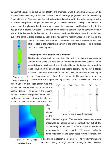
Figure 3: 1 st<br />
Station Buckling<br />
punch sides simultaneously, which exceeded the column strength of the steel.<br />
This resulted in the uncontained portion of the shank buckling. This simulation<br />
result is shown in Figure 3.<br />
2. Redesign of First Station and Simulation<br />
The buckling effect produced from the initial design required extrusions on the<br />
die and punch sides in the first station to be separated into two stations. In the<br />
second design, initial extrusion on the die side was in the first station and the<br />
initial extrusion on the punch side in the second station. This was not a desired<br />
situation because it reduced the number of stations available <strong>for</strong> <strong>for</strong>ming the<br />
large flange and knurl blank. To accommodate this extrusion in the second<br />
station, one of the upset <strong>for</strong>ming stations had to be eliminated. The third<br />
station upset in the initial design was the<br />
station that was removed as a part of the<br />
second design. The upset in the second<br />
station in the initial design was then modified<br />
by having the gap between the die and<br />
punch reduced to make the upset <strong>for</strong>m<br />
Figure 5: 4 th Design<br />
Underfilled Blank<br />
closer<br />
in<br />
shape<br />
to the<br />
C-O St1 St2 St3 St4 St5 St6<br />
Figure 4: 2nd Design Progression<br />
initial third station part. This re-design places much more<br />
importance on getting optimum material flow out of this<br />
second design third station. The fourth station remained the<br />
same since the part going into the fifth die needs to be the<br />
same regardless of the other upset <strong>for</strong>ming changes. The<br />
re-designed progression is in Figure 4. The results from running<br />
the second design through <strong>Simufact</strong>.<strong>for</strong>ming simulation showed