Simufact for Fastener industry
Simufact for Fastener industry
Simufact for Fastener industry

You also want an ePaper? Increase the reach of your titles
YUMPU automatically turns print PDFs into web optimized ePapers that Google loves.
Cold Forged <strong>Fastener</strong> Development utilizing <strong>Simufact</strong>.<strong>for</strong>ming Software<br />
Nathan Crowgey, Vico Products Co., Plymouth, MI, USA<br />
Abstract<br />
This paper considers the process the Vico Products engineering team contemplated during the<br />
development of a fastener in a six station cold <strong>for</strong>ging machine. The fastener being developed is<br />
double flanged and double threaded with a <strong>for</strong>med knurl using 10B21 material. Due to these<br />
features, this part poses many challenges in the <strong>for</strong>ming process. This paper will describe the<br />
stations in the part progression that required improvement and how the <strong>Simufact</strong>.<strong>for</strong>ming<br />
simulation software aided in the development process.<br />
1. Initial Design and Simulation<br />
The baseline tooling design was created using prior successful designs of similar parts Vico<br />
Products has developed. With this fastener being very similar in function, length and diameter, it<br />
was determined that it could be <strong>for</strong>med with the same basic progression. This initial progression<br />
began by extruding down to the shank diameter<br />
from an intermediate wire size on both the die<br />
and punch sides in the first station. Extrusion of<br />
the thread blanks and the <strong>for</strong>ming of the upset<br />
<strong>for</strong> the large flange occurred in the second and<br />
third stations while working on the upset <strong>for</strong> the<br />
large flange. The fourth station then finished<br />
the large flange and knurl blank to complete the<br />
upset <strong>for</strong>ming sequence. Finishing the<br />
progression, the fifth station <strong>for</strong>ms the knurl<br />
while the sixth station <strong>for</strong>ms the small flange.<br />
This basic progression is shown in Figure 2. As<br />
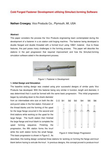
Figure 1: <strong>Fastener</strong> in Development<br />
C-O St1 St2 St3 St4 St5 St6<br />
Figure 2: Initial Design Progression<br />
described, this tooling design contained three stations <strong>for</strong> working on <strong>for</strong>ming the flange and knurl<br />
blank be<strong>for</strong>e having to extrude the knurl. In previous designs, this concept proved to produce knurl
lanks that extrude full and sharp knurl teeth. The progression was then finished with an open die<br />
upset of the smaller flange in the sixth station. This initial design progression was simulated using<br />
<strong>Simufact</strong>.<strong>for</strong>ming. The results of the first station simulation showed that simultaneously extruding<br />
on the die and punch sides per the initial design produced immediate buckling. This in<strong>for</strong>mation<br />
proved useful in allowing the design team to make the necessary modifications to the tooling<br />
design prior to tooling fabrication. Simulation of the following stations was not completed due to<br />
failure of the fastener in the first station. It was concluded that this failure in the first station was<br />
due to the combined load created by open extruding, near the recommended limit, on the die and<br />
Figure 3: 1 st<br />
Station Buckling<br />
punch sides simultaneously, which exceeded the column strength of the steel.<br />
This resulted in the uncontained portion of the shank buckling. This simulation<br />
result is shown in Figure 3.<br />
2. Redesign of First Station and Simulation<br />
The buckling effect produced from the initial design required extrusions on the<br />
die and punch sides in the first station to be separated into two stations. In the<br />
second design, initial extrusion on the die side was in the first station and the<br />
initial extrusion on the punch side in the second station. This was not a desired<br />
situation because it reduced the number of stations available <strong>for</strong> <strong>for</strong>ming the<br />
large flange and knurl blank. To accommodate this extrusion in the second<br />
station, one of the upset <strong>for</strong>ming stations had to be eliminated. The third<br />
station upset in the initial design was the<br />
station that was removed as a part of the<br />
second design. The upset in the second<br />
station in the initial design was then modified<br />
by having the gap between the die and<br />
punch reduced to make the upset <strong>for</strong>m<br />
Figure 5: 4 th Design<br />
Underfilled Blank<br />
closer<br />
in<br />
shape<br />
to the<br />
C-O St1 St2 St3 St4 St5 St6<br />
Figure 4: 2nd Design Progression<br />
initial third station part. This re-design places much more<br />
importance on getting optimum material flow out of this<br />
second design third station. The fourth station remained the<br />
same since the part going into the fifth die needs to be the<br />
same regardless of the other upset <strong>for</strong>ming changes. The<br />
re-designed progression is in Figure 4. The results from running<br />
the second design through <strong>Simufact</strong>.<strong>for</strong>ming simulation showed
that the extrusions in the first and second stations <strong>for</strong>med without any buckling with these design<br />
modifications. Upsetting in the third station <strong>for</strong>med as predicted however, the material did not flow<br />
as planned in the fourth station. The knurl blank did not fully fill out to the dimensional requirements<br />
and there<strong>for</strong>e during simulation of the fifth station, it produced an under filled knurl profile. The<br />
under-filled knurl blank simulation result is shown in Figure 5. The simulation of material flow of<br />
the third station part into the flange cavity in the fourth station also showed that there was a lack of<br />
material in that upset shape, shown in Figure 6. In that<br />
simulation, the material also pulled away from the<br />
undercut feature as it was flowing out into the flange<br />
cavity leaving a void between the die and the material. It<br />
was concluded that the third station upset <strong>for</strong>m would<br />
require modification to provide more material to fill out the<br />
flange cavity as well as a revised shape to aid in filling out<br />
the knurl blank. Due to time constraints, tooling had to be<br />
ordered and this second design had to be sampled in the<br />
machine. The results were consistent with those produced with<br />
the <strong>Simufact</strong>.<strong>for</strong>ming software. Some minor modifications were<br />
made to the tooling during the sample run but those changes did<br />
not make enough of a difference to produce a quality part.<br />
3. Redesign of Upsets<br />
The concept in redesigning the upset stations was to work on the<br />
volumes, angles and lengths of the die and punch shapes so that the<br />
material would flow easily into the flange cavity in the fourth station and<br />
thus fill out the knurl and flange in the fifth station. <strong>Simufact</strong>.<strong>for</strong>ming<br />
provided a lot of in<strong>for</strong>mation to aid in determining how to go about<br />
modifying the third upset. In analyzing the initial and second designs, the<br />
simulation animations illustrated where the material voids occurred and<br />
thus showed where the material needed to be in the third station to<br />
produce the desired results in the fourth station. Using this in<strong>for</strong>mation, it<br />
was concluded that in station 3, the punch side lead angle on the face<br />
needed to be steeper and the shoulder needed to be lengthened. It was<br />
also determined that on the die side the face angle had to be opened up<br />
and pushed deeper. The sum of these changes were intended to aid in<br />
guiding the material outward in a more controlled manner as well as drive<br />
Figure 6: 4 th Station<br />
Under-filled Flange<br />
Figure 7: 3rd<br />
Design Tooling<br />
material down into the knurl shoulder. The third station tool concept is shown in Figure 7. These<br />
modifications did improve the results in simulation and the fourth station did fill out better however,
it was felt that more changes could be made at this stage to produce better results be<strong>for</strong>e<br />
attempting another machine run.<br />
After reviewing this third design and the <strong>Simufact</strong>.<strong>for</strong>ming results, it was determined by the<br />
engineering team that the next design to be simulated would follow a different concept. This<br />
iteration varied by having a counter bore at the face on the punch side instead of an angle leading<br />
into the counter bore as was the case in the previous design. This third punch design is shown in<br />
Figure 8. In this fourth design, the assumption was that the material would first fill into the counter<br />
bore and then upset into the gap between the die and punch. The results of this situation were<br />
good in simulation. The first and second stations remained unchanged from the previous two<br />
designs. In the third station the material filled into the counter bore and upset between the die and<br />
punch sides. In the fourth station, the part <strong>for</strong>med in the third station filled into the knurl shoulder<br />
and into the flange cavity providing a fully filled out fourth station<br />
part. The part <strong>for</strong>med in the fourth station was simulated in the fifth<br />
station as well and the resulting part displayed a fully filled out knurl<br />
profile. With this outcome the fourth design was tooled up and set<br />
up in the machine. However, the actual results from manufacturing<br />
run did not match the simulation results. The engineering team<br />
concluded that this was because in the third station of the sample<br />
run, the material did not fill into the counter bore fully as was displayed in simulation which resulted<br />
in a lack of material in the fourth station to fill the knurl blank. This under- filled counter bore in the<br />
third station was due to oil and material coating residue being trapped into the corner of the punch<br />
counter bore preventing the material from flowing all the way in. Due to this condition the third<br />
station counter bore on this header run was actually more under filled than with the previous<br />
design.<br />
On the fifth and final design, a steep angle was placed at the face of the third station punch going<br />
back to the thread blank with no intermediate counter bore. This punch design is shown in Figure<br />
9. Initially this did not seem like it would provide the best results in<br />
material flow and filling out the corners and cavities in the fourth<br />
station but it was ran through <strong>Simufact</strong>.<strong>for</strong>ming and displayed the<br />
best balance of filling out the knurl blank as well as fully filling out<br />
the flange <strong>for</strong>m without excessive flashing in between the die and<br />
punch. This design was run in the last header trial and provided<br />
improved results. The parts produced in third and fourth stations<br />
Figure 8: 4th<br />
Design Punch<br />
Figure 9: 5th Design Punch<br />
were then able to continue on to the last two stations. Being able to run through several iterations<br />
using simulation in a relatively short period of time was very beneficial in developing a successful<br />
progression and being able to simulate ideas and designs that may otherwise have been passed<br />
over or ruled out because of the time and cost in manufacturing each iteration in the header. Once
passing through the upsetting stations with the desired blank, the knurl and open die stations<br />
worked with little adjustment or modification.<br />
4. Knurl and Open Die Stages<br />
While the primary struggles experienced on this part were in manipulating the upset <strong>for</strong>ms, the fifth<br />
and sixth stations still benefited from simulating their <strong>for</strong>ming processes. The knurl extrusion on<br />
the initial design of the fifth station did not <strong>for</strong>m the knurls as fully and<br />
cleanly as anticipated even though the entering blank was filled. It<br />
was initially assumed that the diameter of the knurl blank needed to<br />
be increased however it could not be proven. While this job was still<br />
in the machine, the engineering team was able to set up another<br />
Figure 11: 5 th Station Filled Knurl<br />
simulation trial to attempt to<br />
replicate the situation in the fifth<br />
station, to see what was causing<br />
the under-filled condition. The<br />
animation of that simulation<br />
showed increasing strain at the<br />
start of the knurl extrude as the part<br />
pushed into the punch and also showed the knurl starting to<br />
under fill as seen at the machine. The under-filled fifth station<br />
simulation is shown in Figure 10. With this in<strong>for</strong>mation,<br />
another simulation was set up with a modification to the lead-<br />
in angle and radius of the knurl extrude in an attempt to reduce that resistance and the knurl filled<br />
out fully. The results of that simulation produced a full, sharp knurl that <strong>for</strong>med with less<br />
resistance. The simulated full knurl is shown in Figure 11. This verified that the knurl blank was<br />
correct and that it was the knurl extrude that needed to be modified. At the machine, the fifth<br />
punch knurl extrude was modified according to the simulated fifth punch and the knurl filled very<br />
similarly to the simulation animation.<br />
In the sixth station, using the results from the newly re-designed fifth<br />
station simulation, the first simulation was evaluated and it produced<br />
a finished part very close to design specifications with no<br />
modifications, shown in Figure 12. Analyzing the simulation results, it<br />
was determined that the design of the tooling <strong>for</strong> this station was<br />
acceptable however some minor adjustments needed to be made at<br />
the machine to get the finish part fully to the print specifications.<br />
Making these small changes did bring the part into the print<br />
specification and Vico Products was then able to finish the rest of the<br />
processing of this part to submit a sample to the customer.<br />
Figure 10: 5 th Station<br />
Under filled Knurl<br />
Figure 12: 6 th Station<br />
Filled Out Open Die
5. Conclusion<br />
The application of the <strong>Simufact</strong>.<strong>for</strong>ming Simulation software provided invaluable in<strong>for</strong>mation at a<br />
critical time in the design process. It af<strong>for</strong>ded the opportunity to see how the initial design <strong>for</strong>med<br />
and allowed multiple iterations to be made to the design prior to purchasing any tooling. In<br />
addition after each machine run, the simulation software was able to provide valuable insight into<br />
what was actually going on with the material flow so further development and re-design could head<br />
in the most practical and efficient direction. The progress attained from simulation in the refining of<br />
the upset <strong>for</strong>ming on this part allowed <strong>for</strong> fewer machine runs as well as providing more confidence<br />
in the design and manufacturing results. Past development of similar parts took a great deal more<br />
time and resources to achieve the same result.