Manuale uso manutenzione
Manuale uso manutenzione
Manuale uso manutenzione

Create successful ePaper yourself
Turn your PDF publications into a flip-book with our unique Google optimized e-Paper software.
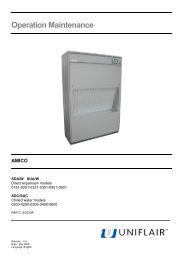
Instruction Manual<br />
AQUAFLAIR<br />
BREC<br />
Air-cooled water chillers<br />
BREF<br />
Air-cooled water chillers with free-cooling system<br />
1602A - 1802A - 2202A - 2502A - 2802A - 3202A - 3602A - 4202A - 4802A<br />
R134a (300-1050 kW)<br />
EN<br />
06MM108@00B0100<br />
05/11/2008
UNIFLAIR SpA policy is one of continuous technological innovation and the Company therefore reserves the<br />
right to amend any data herein without prior notice.<br />
2<br />
Prepared by:<br />
A.Schimicci<br />
Verified by:<br />
M.Salvagno<br />
06MM104@00B0100<br />
05/11/2008<br />
Approved by:<br />
D.Marchetti
USE AND MAINTENANCE MANUAL<br />
Index<br />
SYMBOLS USED ............................................................................................................................................................. 4<br />
WARNING ................................................................................................................................................................... 5<br />
GENERAL ........................................................................................................................................................................... 5<br />
LOW OUTDOOR AIR TEMPERATURE ................................................................................................................................. 6<br />
SAFETY .......................................................................................................................................................................... 7<br />
DOCUMENTATION INCLUDED WITH THE UNIT .............................................................................................................. 8<br />
DATA PLATE .................................................................................................................................................................. 8<br />
DIMENSIONS AND WEIGHTS ......................................................................................................................................... 9<br />
INSTALLATION ............................................................................................................................................................ 10<br />
TRANSPORT AND HANDLING .......................................................................................................................................... 10<br />
RECEIVING AND STORING THE UNIT ............................................................................................................................... 10<br />
ANTI-VIBRATION SUPPORTS .......................................................................................................................................... 11<br />
HYDRAULIC CONNECTIONS ............................................................................................................................................. 12<br />
EXAMPLE OF UNIT INSTALLATION WITH OR WITHOUT PUMP ........................................................................................ 13<br />
FILLING OF THE WATER CIRCUIT .............................................................................................................................................. 14<br />
ELECTRICAL CONNECTIONS ............................................................................................................................................ 15<br />
GENERAL INSTRUCTIONS CONNECTION TO MAINS SUPPLY ........................................................................................... 15<br />
FITTING THE OPTIONAL RS 485 BOARD ........................................................................................................................... 17<br />
STARTUP AND TESTING CHECK LIST ................................................................................................................................ 18<br />
PROGRAMMING AND REGULATION ............................................................................................................................... 19<br />
PROGRAM VERSION ........................................................................................................................................................ 19<br />
SEMI-HERMETIC COMPACT SCREWS START-UP PROCEDURE ....................................................................................... 20<br />
SETTING THE SAFETY DEVICE .......................................................................................................................................... 21<br />
MAINTENANCE AND REPLACING COMPONENTS ......................................................................................................... 22<br />
REFRIGERANT CHARGE .......................................................................................................................................................... 22<br />
REFRIGERANT CONTENT ........................................................................................................................................................ 23<br />
DRAINING THE WATER CIRCUIT ............................................................................................................................................... 23<br />
MAINTENANCE AND CLEANING .................................................................................................................................. 25<br />
MAINTENANCE PROGRAMME .................................................................................................................................... 26<br />
TECHNICAL DATA ........................................................................................................................................................ 27<br />
WATER CIRCUIT CAPACITY .............................................................................................................................................. 27<br />
RECOMMENDED MINIMUM PLANT CAPACITY ............................................................................................................... 27<br />
MAXIMUM WORKING PRESSURE OF HYDRAULIC CIRCUIT ............................................................................................. 27<br />
COMPRESSOR OIL ........................................................................................................................................................... 27<br />
EVAPORATOR PRESSURE DROP ..................................................................................................................................... 28<br />
PUMP HEAD PRESSURE AND UNIT PRESSURE DROPS ..................................................................................................... 29<br />
PARTIAL HEAT RECOVERY ........................................................................................................................................... 31<br />
OPERATING LIMIT ....................................................................................................................................................... 32<br />
BREC................................................................................................................................................................................ 32<br />
BREF ................................................................................................................................................................................ 33<br />
ELECTRICAL DATA ....................................................................................................................................................... 34<br />
PROBLEM SOLVING ..................................................................................................................................................... 44<br />
GUIDE TO TROUBLESHOOTING ................................................................................................................................... 44<br />
06MM108@00B0100 3<br />
05/11/2008
4<br />
SYMBOLS USED<br />
06MM108@00B0100<br />
05/11/2008<br />
USE AND MAINTENANCE MANUAL<br />
SYMBOL MEANING SYMBOL MEANING<br />
DANGER<br />
MOVING COMPONENTS<br />
IMPORTANT WARNING<br />
HIGH VOLTAGE – ELECTRICAL<br />
RISK<br />
FRAGILE: handle with care.<br />
PROTECT AGAINST<br />
MOISTURE: the packaged unit<br />
must be stored in a dry place.<br />
CENTRE OF GRAVITY: shows<br />
the centre of gravity of the<br />
packaged unit.<br />
KEEP AWAY FROM HEAT: the<br />
unit must be kept away from heat<br />
sources.<br />
HOT SURFACES – DANGER OF<br />
BURNING<br />
SHARP EDGES<br />
THIS SIDE UP shows the<br />
orientation of the unit.<br />
TEMPERATURE LIMITS: the unit<br />
must not be stored outside these<br />
limits.<br />
NO HOOKS: do not use hooks to<br />
lift the packed unit.<br />
DO NOT STACK.
USE AND MAINTENANCE MANUAL<br />
GENERAL<br />
WARNING<br />
This unit has been subjected to risk analysis under EC Directive 98/37/CEE (89/392/CEE). The technical<br />
solutions implemented during the design phase are described in the unit‟s technical file.<br />
This equipment is manufactured to function safely for the purposes for which it was designed, as long as the<br />
installation, operation and maintenance are carried out according to the instructions in this manual and the<br />
labels attached to the unit.<br />
In compliance with European Community Directive 94/9/CE these units are not to be used in potentially<br />
explosive environments.<br />
This machine is subject to the European Community Directive 97/23/EEC regarding<br />
Pressure Equipment. Any intervention on the pressure circuit must be authorized by<br />
Uniflair, and the personnel must be approved by Uniflair. If any of the following components:<br />
compressors, liquid receivers, safety valves, refrigerant pressostats are to be replaced,<br />
Uniflair must be immediately informed of the serial number of the new devices and the<br />
devices replaced, otherwise Uniflair shall not guarantee the integrity of the equipment.<br />
Additionally, if any soldered joint needs to be repaired on site, Uniflair must be immediately<br />
informed which joint and the name of the engineer.<br />
This unit contains refrigerant gas circuits, chilled water under pressure, live electrical components,<br />
hot surfaces, sharp edges (the fins on the coils) and rotating devices such as the fans.<br />
All service and maintenance operations which require access to the inside of the unit while<br />
it is in operation must be performed by qualified and experienced personnel who are aware<br />
of the necessary precautions.<br />
06MM108@00B0100 5<br />
05/11/2008
Before accessing the inside of the unit, disconnect it from the electrical power supply.<br />
In any case, all safety legislation regarding the installation location must be followed.<br />
6<br />
06MM108@00B0100<br />
05/11/2008<br />
USE AND MAINTENANCE MANUAL<br />
In the event of fire, water and other conductive substances must not be used to extinguish the fire near live<br />
electrical components. This warning must be displayed on notices in the unit installation location.<br />
If the refrigerants used come into contact with fire they decompose, forming acids and other irritants. The<br />
smell of these substances, even at concentrations below the danger levels, gives enough warning to allow<br />
evacuation of the area at risk.<br />
Make sure that the mains supply to the unit is the same as that shown on the data plate.<br />
Free cooling chillers must be loaded with anti-freeze.<br />
If the unit is fitted with the optional heating cable, it must be turned off without cutting the electrical power<br />
supply.<br />
Install a mechanical filter in the section of tubing near the intake of the unit to prevent the heat<br />
exchanger being blocked with pieces of welding or flakes of oxidised metal from the water mains.<br />
LOW OUTDOOR AIR TEMPERATURE<br />
Units without free-cooling: drain all the water from the system before the winter to avoid freezing.<br />
In periods in which the temperature may fall below 0°C, empty the unit in order to prevent serious damage<br />
caused by the formation of ice.<br />
This precaution is not necessary if the unit is charged with an appropriate anti-freeze mixture.<br />
Air-cooled water chillers with the free-cooling system must be loaded with anti-freeze mixture.
USE AND MAINTENANCE MANUAL<br />
SAFETY<br />
The new range of AQUAFLAIR water chillers and heat pumps features state-of-the-art technology<br />
ensuring maximum reliability, safety, quiet operation and respect for the environment.<br />
1) RELIABILITY: Trouble-free operation of Uniflair precision chillers is ensured by rigorous<br />
production process controls under ISO 9001-certified quality procedures:<br />
quality control of components;<br />
pressure testing of refrigerant and water circuits;<br />
testing of current absorption and IEC safety testing;<br />
calibration and testing of instruments and safety devices;<br />
final testing of the unit under operating conditions.<br />
2) ACTIVE SAFETY: UNIFLAIR safety and control systems have a supervision and prevention<br />
function with:<br />
automatic blocking of components in dangerous conditions;<br />
indication of function status; reading and continuous display of circulating fluid<br />
temperature;<br />
management of compressor start-ups to reduce excessive switching on and off;<br />
compressor start timing to reduce total unit start-up current;<br />
indication of anomalous operating conditions and/or alarms.<br />
3) PASSIVE SAFETY: The essential functions of UNIFLAIR chillers are protected against<br />
anomalous function conditions and potential damage by:<br />
high and low pressure switches on the refrigerant circuit (HP with manual re-set);<br />
safety valve on the high pressure refrigerant line;<br />
anti-freeze protection to prevent freezing of the evaporator, pump and tank;<br />
compressor motor electrical protection;<br />
water circuit safety (with optional pump group);<br />
compressor crankcase heater (standard on free-cooling and heat pump versions).<br />
4) PERSONAL SAFETY. The design and cabling of all UNIFLAIR chillers conforms to IEC<br />
electro-technical norms. Electrical panels have auxiliary 24V circuits and are equipped with:<br />
general switch and door lock switch;<br />
automatic circuit-breaker switches;<br />
double protection panel on fan compartment.<br />
The fans are protected on both sides by an external metal grille which conforms to applicable safety<br />
norms.<br />
06MM108@00B0100 7<br />
05/11/2008
8<br />
06MM108@00B0100<br />
05/11/2008<br />
USE AND MAINTENANCE MANUAL<br />
DOCUMENTATION INCLUDED WITH THE UNIT<br />
Each AQUAFLAIR chiller is delivered complete with the following documentation:<br />
BRE and microprocessor control instruction manuals<br />
Unit installation diagrams<br />
Diagrams of the refrigerant and hydraulic circuits of the unit<br />
Electrical diagrams<br />
List of spare parts<br />
CE declaration with list of European directives and norms to which the unit conforms<br />
Warranty Conditions<br />
The chiller data plate is in the electrical panel<br />
and gives the following information:<br />
Model of the unit<br />
Serial number<br />
Voltage, number of phases and power<br />
supply frequency for primary and auxiliary<br />
circuits<br />
Current and power absorbed<br />
OA (Operating current), FLA (Full load<br />
current) and LRA ( Locked rotor current )<br />
Safety device settings<br />
Refrigerant type and charge in kg for each<br />
circuit.<br />
DATA PLATE<br />
MODEL SERIAL No.<br />
POWER SUPPLY VOLTAGE<br />
CURRENT<br />
OA FLA LRA KW TOTAL<br />
SAFETY DEVICE SETTINGS<br />
REFRIGERANT<br />
REFRIGERANT TYPE O.D.P. G.W.P. T.E.W.I.(*)<br />
R134 HFC 0 1300 1821<br />
(*) for year, specific (each kW, each year), with assumed total refrigerant recovery factor at end of life ( =1)
USE AND MAINTENANCE MANUAL<br />
DIMENSIONS AND WEIGHTS<br />
BREC - F 1602A 1802A 2202A 2502A 2802A 3202A 3602A 4202A 4802A<br />
Height (**) mm 2510 2510 2510 2510 2510 2510 2510 2510 2510<br />
Depth mm 4985 4985 6415 6415 6415 8890 8890 10320 10320<br />
Width mm 2250 2250 2250 2250 2250 2250 2250 2250 2250<br />
Weights (BREC)<br />
Weight (basic version,<br />
(*) Kg 3961 4317 4583 4611 5095 6304 6604 7321 7360<br />
without hydraulic kit)<br />
Weight (basic version<br />
with 1 pump) (*)<br />
Weight (version with 2<br />
pumps) (*)<br />
Weights (BREF)<br />
Kg 4111 4467 4748 4776 5260 6654 6954 7621 7660<br />
Kg 4271 4627 4929 4957 5441 7035 7335 7928 7967<br />
Weight (basic version,<br />
(*) Kg 4677 5121 5546 5574 5936 7402 7702 8843 8882<br />
without hydraulic kit)<br />
Weight (basic version<br />
with 1 pump) (*)<br />
Weight (version with 2<br />
pumps) (*)<br />
Options<br />
Kg 4827 5271 5711 5739 6101 7752 8052 9143 9182<br />
Kg 4989 5433 5896 5924 6286 8133 8433 9450 9489<br />
Partial heat recovery Kg 80 80 110 110 110 300 300 320 320<br />
Ultra low noise version Kg 200 200 200 200 200 505 505 550 550<br />
Economizer Kg 35 35 45 45 45 80 80 85 85<br />
(*) with empty hydraulic circuit<br />
(**) without vibration supports<br />
06MM108@00B0100<br />
05/11/2008<br />
9
TRANSPORT AND HANDLING<br />
10<br />
INSTALLATION<br />
06MM108@00B0100<br />
05/11/2008<br />
USE AND MAINTENANCE MANUAL<br />
Move the unit as near to the installation site as possible before removing packaging. The unit must be lifted<br />
using equipment and procedures illustrated in the drawings in the documentation attached.<br />
Check the drawings attached to the unit or the installation drawings included in the machine<br />
documentation.<br />
Unit dimensions are given in the technical data tables and installation drawings included.<br />
RECEIVING AND STORING THE UNIT<br />
Each unit leaves the factory in perfect condition. Therefore please check the unit very carefully on<br />
delivery and notify the transport company immediately and in writing of any damage which may<br />
have been caused during transportation.<br />
Respect the storage temperature : -15 +50°C<br />
Do not expose to the solar ray<br />
Check that the load capacity of the floor is sufficient to support the weight of the unit.<br />
The unit must be set on a solid, level surface. Once positioned, level the unit with the aid of a suitable spirit<br />
level using the adjustable feet and, where necessary, shims: the gradient should not exceed 0.5 degrees<br />
under any circumstances.<br />
The unit must not be turned on its side or upside down.
USE AND MAINTENANCE MANUAL<br />
POSITIONING THE UNIT – OPERATING SPACE<br />
For lifting the unit it is necessary to consult<br />
the drawings attached to the documentation<br />
This unit has been built for outdoor installation and therefore with a free flow of air to the condensing coil.<br />
The air flow aspirated by the fans through the condensing coil must not be blocked in order not to affect the<br />
unit‟s efficiency and to avoid the safety devices intervening.<br />
In any case, the safety standards in force on the installation site must be respected as well as the minimum<br />
distances indicated (see operating space paragraph), they must also be respected when any maintenance is<br />
carried out.<br />
Avoid installation in particularly harsh environments (in this case please contact Uniflair S.p.A. for possible<br />
technical solutions.)<br />
The rubber or spring anti-vibration supports (both optional) reduce the transmission of vibrations to the<br />
support slab.<br />
Note: The dimensions are in mm.<br />
Verify the placing of the unit on the roof/floor. The unit should be<br />
placed on anti-vibration supports (rubber or spring type depending<br />
on the type of application) in order to reduce the vibration levels.<br />
The unit must be placed perfectly horizontally.<br />
ANTI-VIBRATION SUPPORTS<br />
To reduce vibrations, AQUAFLAIR B.R.E units can be supplied with antivibration<br />
supports.<br />
Uniflair has selected spring supports for its units.<br />
They are composed of C72 steel with epoxy painted springs, the bases<br />
are made of elastomer with a metal insert. These supports allow<br />
considerable yielding while being highly compact. As a result, they are<br />
particularly efficient in insulating low frequencies, typical of machines,<br />
such as refrigerators, running at low revs.<br />
Moreover, their design enables them to be used in particularly difficult<br />
and/or aggressive environments, as the supports are highly resistant to<br />
oils, corrosion and high temperatures.<br />
06MM108@00B0100<br />
05/11/2008<br />
11
HYDRAULIC CONNECTIONS<br />
12<br />
06MM108@00B0100<br />
05/11/2008<br />
USE AND MAINTENANCE MANUAL<br />
For a welded hydraulic connection use the “stub pipes” which are supplied, or connect the<br />
unit directly by using pipes channeled into the unit using a victaulic joint, ensuring that the<br />
joint gasket is adequately embedded.<br />
1) CHECK that the section of chilled water pipes and the circulation pump fitted are adequate.<br />
An inadequate water flow significantly reduces the cooling capacity of the unit.<br />
2) CHECK the water inlet/outlet directions. There are labels next to the inlet, outlet and heat<br />
recovery connections as shown in the diagram below.<br />
INGRESSO - INLET<br />
EINGANG - ENTREE<br />
ENTRADA<br />
I ev<br />
USCITA - OUTLET<br />
AUSGANG - SORTIE<br />
U ev<br />
SALIDA<br />
3) Connect the chiller using flexible tubes to stop the transmission of vibrations. Fit shut-off<br />
valves so that the unit can be isolated from the water circuit;<br />
4) Insulate the chilled water pipes to stop the formation of condensation;<br />
5) Fit temperature measuring points on the pipes near the inlet and outlet connections;<br />
6) Install a metal filter in the section of pipe next to the unit intake to prevent pieces of welding<br />
or flakes of rust entering the heat exchanger;<br />
7) Provide a discharge well so that the unit can be emptied when necessary.<br />
BREC- BREF 1602A 1802A 2202A 2502A 2802A 3202A 3602A 4202A 4802A<br />
Victaulic hydraulic<br />
connections<br />
4” 4” 4” 4” 5” 5” 5” 6” 6”
USE AND MAINTENANCE MANUAL<br />
EXAMPLE OF UNIT INSTALLATION WITH OR WITHOUT PUMP<br />
UNIT<br />
WITH<br />
PUMP<br />
VE EXPANSION VESSEL<br />
GR FILL IN<br />
PUMP<br />
AUTOMATIC AIR VALVE<br />
UNIT<br />
WITHOUT PUMP<br />
Limit of equipment<br />
Limit of equipment<br />
VE<br />
06MM108@00B0100<br />
05/11/2008<br />
SAFETY VALVE<br />
VALVE<br />
GR<br />
MECHANICAL FILTER<br />
MANOMETER<br />
GR<br />
To the user<br />
From user<br />
To the user<br />
From user<br />
13
14<br />
06MM108@00B0100<br />
05/11/2008<br />
USE AND MAINTENANCE MANUAL<br />
Filling of the water circuit<br />
Once the unit is connected to the installation of the user it is possible to proceed with filling it with<br />
water ( or water + Glycol ) allowing the air present in the pipes to escape by means of the installer‟s<br />
predisposed valves.<br />
For models with free-cooling (BREF) remove the panels on the right side of the unit and allow the air<br />
to escape by means of the appropriate screw valves as indicated in the following designs.<br />
During the filling phase of the free-cooling circuit it is also necessary to allow the air to escape from<br />
the pipes above the pump to avoid cavitation and any consequent damage to the pump.<br />
Panels to be<br />
removed on<br />
this side<br />
Valve<br />
Important: if a possible stop during winter is predicted, it is necessary<br />
to completely empty the hydraulic circuit adding the necessary quantity<br />
of glycol to the remaining water in the unit.<br />
Valve Valve<br />
Glycol water mixtures can be cooled down to -15°C as long as the water in the circuit<br />
contains sufficient antifreeze to prevent freezing inside the evaporator<br />
Minimum fluid temperature with unit<br />
operating<br />
Free cooling<br />
pump<br />
5,0 °C 3,0 °C -5,0 °C -10,0 °C -18,0 °C -28,0°C<br />
Freezing temperature 0 °C -4,4 °C -9,6 °C -16,1 °C -24,5 °C -35,5 °C<br />
Percentage of ethylene glycol by weight 0% 10% 20% 30% 40% 50%
USE AND MAINTENANCE MANUAL<br />
ELECTRICAL CONNECTIONS<br />
Before performing any work on electrical parts, make sure they are not connected to the power<br />
supply.<br />
In order to prevent accidents and for the chiller to provide good, lasting, continuous service, it is<br />
essential that wiring is carried out correctly, in a professional manner and in accordance with the<br />
regulations in force.<br />
GENERAL INSTRUCTIONS CONNECTION TO MAINS SUPPLY<br />
To connect the power cables, remove the cover plate on the bottom of the unit.<br />
Since the unit is placed outdoors, IP55 insulation protection must be maintained, therefore<br />
suitable cable clamps/sheath clamps and/or junction boxes must be used.<br />
Cables must be connected by first removing the Plexiglas cover protecting the poles of the<br />
disconnector and then fastening the wire terminals of the cables to the relevant holes<br />
provided for this purpose.<br />
Once this has been done, make sure the cover is re-positioned.<br />
It is vital the phases are connected correctly in the position indicated on the wiring diagram<br />
which is supplied with the unit as if they are connected in any other way, the unit will not<br />
work.<br />
Particular attention must be given to the following:<br />
Electrical connections must be carried out by qualified installers.<br />
Power leads must be protected upstream against the effects of<br />
short-circuits and current overload.<br />
06MM108@00B0100<br />
05/11/2008<br />
15
DESCRIPTION OF PROCEDURE<br />
16<br />
06MM108@00B0100<br />
05/11/2008<br />
USE AND MAINTENANCE MANUAL<br />
1) OPEN the door of the master electrical panel which is located on the front of the unit above the<br />
compressor compartment;<br />
2) MAKE SURE that the mains voltage matches the voltage given on the data plate of the unit (voltage,<br />
number and frequency of the phases);<br />
3) INTRODUCE the feeding cable through the flange in the position indicated in the diagram.<br />
Remove the flange which is placed low on the left of the unit, and make the necessary entry holes (this must<br />
be done in such a way as to fix the cable to the upright of the unit until it reaches the electrical panel).<br />
There is an extractable flange on the left of the base of the electrical panel and two holes on the right hand<br />
side to allow the power supply and signal cables to enter.<br />
a. for the power supply cables, which will be connected to the terminals on the IG general switch on the<br />
left hand side of the electrical panel, it is necessary to unscrew the flange and make two holes where<br />
needed.<br />
b. for the signal cables, which will be connected to the terminals on the microprocessor board on the<br />
right hand side of the electrical panel, only the plugs on the holes which have already been made<br />
need to be removed.<br />
The power supply lead is not supplied by UNIFLAIR S.p.A and the installer must choose an appropriately<br />
sized cable.<br />
The power lead‟s cross-section must be chosen based on the length of the lead, how it is to be laid, the<br />
chiller's maximum current demand, and in such a way that an excessive drop in voltage is avoided (the<br />
supply voltage must be within ± 10% of the rated value).<br />
The power supply connection must be supported by the entry flange provided for this purpose.<br />
Supply cable<br />
entrance
USE AND MAINTENANCE MANUAL<br />
4) CONNECT the three power phases to the terminals of the IG master switch, making sure beforehand that<br />
none of the electrical parts are live.<br />
Ensure the wires are properly fitted in the respective terminals and tighten the screws as far as they will go.<br />
It is possible to switch the unit on and off or switch between cooling and heating mode using remote switches:<br />
5) CONNECT the remote ON/OFF switch to terminals 20 and 50 on the terminal board of the electrical panel;<br />
6) CONNECT the remote alarm warning (if there is no remote user terminal):<br />
7) USE the switching contact (terminals 961, 960, 962) for signalling type-A alarms (971,970,972) for type-B<br />
alarms (see controller's manual).<br />
8) Close the IG master switch followed by the IM9 switch and then make sure the two LEDs on the RSF<br />
phase sequence relay, which is located at the top of the panel, come on.<br />
If this doesn‟t happen, check the power supply or swap over the two phases of the power lead.<br />
FITTING THE OPTIONAL RS 485 BOARD<br />
1. Disconnect the power supply to the board;<br />
2. Insert the RS485 card on the SERIAL<br />
connector of the main board;<br />
3. Respect the polarities shown when connecting<br />
the serial line;<br />
4. The serial line must be closed by means of a<br />
120 - 1/4W resistance, placed between the<br />
TX/RX+ and TX/RX- terminals of the board at<br />
the end line of the network.<br />
The serial address is set via the user terminal using<br />
the relevant functions (see controller's manual)<br />
06MM108@00B0100<br />
05/11/2008<br />
Income key for the programming<br />
PCO1<br />
Analog input housing Serial card housing<br />
17
STARTUP AND TESTING CHECK LIST<br />
Before starting-up the unit, read the enclosed section on<br />
Commissioning the first start-up for screw compressors<br />
Once installation is complete, follow the procedure illustrated:<br />
18<br />
06MM108@00B0100<br />
05/11/2008<br />
USE AND MAINTENANCE MANUAL<br />
Tighten all the electrical terminal connections<br />
Verify the correct mains voltage<br />
Verify the gas circuit pressures (manometer).<br />
Verify the percentage of glycol present in the hydraulic circuit.<br />
Close the IG master switch electrical panel, making sure beforehand that the power supply phases<br />
are properly connected<br />
OIL HEATING :<br />
after the unit has been connected to the power supply, (with the IG master<br />
switch in position ON, the IM9 closed and the unit switched off from the user<br />
terminal ) wait 12 hours before starting the system in order to heat the oil<br />
of the compressors sufficiently. Do not switch off the power during<br />
weekly breaks in operation. When left idle for longer periods, the<br />
refrigerant may migrate into the compressor casing of its own accord.<br />
This may result in the oil foaming when the machine is switched on, which<br />
is liable to lead to damage because of insufficient purification.<br />
When the power is supplied to the auxiliary circuit of the electrical panel (IM9) the control is<br />
activated as follows:<br />
the yellow led lights up indicating that there is a power supply to the master board (see master<br />
board layout )<br />
a short audible signal is heard<br />
the display shows the start screen for 10 seconds before switching to unit stopped status<br />
when the unit is powered but not running, 3 fields are active on the user terminal display: Time and<br />
current date (only in units featuring a clock card), return water temperature, external temperature<br />
(only units featuring free-cooling), and one of the following messages indicating how the unit has<br />
been switched off : ON/OFF button, supervisory system, time programme or manual override.<br />
WATER IN TEMP. . . . . °C<br />
WATER OUT TEMP. . . . . °C<br />
UNIT OFF<br />
Start the unit (read the section on commissioning screw compressors first) by pressing the on-off<br />
key on the user terminal.<br />
Make sure none of the red alarm LEDs are lit : if an LED lights up, refer to the “Problem solving<br />
guide” section and instructions given in the microprocessor control manual. To switch off the unit,<br />
use the local terminal to allow the pumps to stop at least 10 seconds after the chiller, thus<br />
preventing the chiller from stopping in no-flow conditions
USE AND MAINTENANCE MANUAL<br />
PROGRAMMING AND REGULATION<br />
This system, which is able to be programmed according to the specific needs of its user, is<br />
particularly suitable for technological applications since it enables independent control of all of the<br />
on/off switches on the compressors.<br />
The regulation program, which can be found in the FLASH EPROM memory (base card), is<br />
identified by an alphanumeric code, the logic of which is explained here below.<br />
Control parameters (set points, alarms) and display of data and events (reading of set points and control<br />
values, operating events or/and alarms) are all programmed through the User terminal as shown below<br />
PROGRAM VERSION<br />
Press to view the program version which has been installed in the<br />
Flash Eprom memory.<br />
You will need this information when several units are to be connected to a<br />
local LAN network, all of the units which are connected must have the<br />
same program version.<br />
When using a service centre, it is important to inform the technicians which<br />
version of the regulation program is installed in the Flash Eprom.<br />
UPC1m board<br />
06MM108@00B0100<br />
05/11/2008<br />
Versione del Programma<br />
(120 screw)<br />
19
SEMI-HERMETIC COMPACT SCREWS START-UP PROCEDURE<br />
CHECKING THE ROTATION DIRECTION<br />
20<br />
06MM108@00B0100<br />
05/11/2008<br />
USE AND MAINTENANCE MANUAL<br />
Attention!<br />
Danger of severe compressor damage.<br />
Operate screw compressors only in the prescribed rotation direction.<br />
Despite the phase sequence control by the INT69VSY-II protection device, a test is recommended.<br />
Rotation direction check with mounted suction shut-off valve:<br />
• Connect a gauge to the suction shut-off valve.<br />
• Close the valve and then open it again with one turn.<br />
• Start the compressor briefly (approx. 0.5 .. 1 s).<br />
• Correct rotating direction: the suction pressure drops immediately.<br />
• Wrong rotating direction: the pressure increases or the protection device shuts off.<br />
Invert the polarity of the terminals on the common supply line.<br />
Rotation direction check without suction shut-off valve:<br />
• Close the solenoid valves (evaporator and economiser).<br />
• Start the compressor briefly (approx. 0.5 .. 1 s).<br />
• The changes in pressure are noticeably reduced compared to a throttled suction shut-off valve.<br />
• Correct rotating direction: the suction pressure drops.<br />
• Wrong rotating direction: the pressure remains unchanged, increases or the protection device<br />
shuts off.<br />
Invert the polarity of the terminals on the common supply line.<br />
Start-up<br />
Start the compressor again and slowly open the suction shut-off valve.<br />
Lubrication / oil check<br />
The compressor lubrication should be checked immediately after the unit is started up.<br />
• Oil level visible inside the sight glass or slightly below (repeat this check during the first hours of<br />
operation).<br />
• Oil foam can be generated during the starting phase, but should reduce under stable operating<br />
conditions, otherwise this can indicate excessive liquid in the suction gas.<br />
WHEN THE UNIT IS RUNNING AT FULL LOAD<br />
Check that the liquid supercooling at the thermostatic intake is<br />
5 to 10°C less than the condensation temperature on the<br />
manometer scale and that the superheating is between 5 and 8°C.<br />
NOTE: when charging with R134a check the liquid supercooling<br />
value (5 to 10°C) in the sight glass.
USE AND MAINTENANCE MANUAL<br />
SETTING THE SAFETY DEVICE<br />
The function parameter values set on the microprocessor control are given in the enclosed<br />
instruction manual. The table below gives the settings of the safety devices; these are also on the<br />
data plate on the unit.<br />
Component Circuit 1 Circuit 2<br />
High pressure swich barg 22,5 22,5<br />
Low pressure sensor barg 0,3 0,3<br />
High safety pressure valve barg 25 25<br />
Low safety pressure valve barg 16 16<br />
06MM108@00B0100<br />
05/11/2008<br />
21
22<br />
06MM108@00B0100<br />
05/11/2008<br />
USE AND MAINTENANCE MANUAL<br />
MAINTENANCE AND REPLACING COMPONENTS<br />
Disconnect the unit from the electric power supply before<br />
accessing internal components.<br />
All service and maintenance operations which require access to the<br />
internal components of the unit while it is operating must be carried<br />
out by qualified experts who are aware of the necessary precautions to take.<br />
Refrigerant charge<br />
Units are pre-charged in the factory and do not need re-charging unless there have been problems<br />
during transport or installation or if the safety valve has intervened. If it is necessary to adjust the<br />
charge, follow the instructions below. If the circuit has been drained for the replacement of<br />
components, a vacuum must be<br />
created in the circuit before re-<br />
charging.<br />
CREATING A VACUUM IN THE<br />
CIRCUIT<br />
Connect the vacuum pump to the<br />
valves in the compressor housing<br />
and take the vacuum in the system to<br />
0.3 mbar; remember that the vacuum<br />
must not be created too quickly (at<br />
least 120 minutes). When the<br />
vacuum level is reached, maintain it<br />
for at least 60 minutes.<br />
Charge<br />
connection<br />
Electric valve<br />
ETF<br />
Filter drier Sight<br />
glass<br />
Compressor<br />
Pressostat connection<br />
Thermostatic<br />
valve<br />
Charge<br />
connection<br />
Evaporator<br />
REFRIGERANT CHARGE<br />
The system must be charged with Refrigerant charge connections<br />
liquid refrigerant fluid via the needle<br />
valve between the thermostatic<br />
expansion valve and the evaporator until there are no bubbles in the flow sight glass.<br />
The charge must be carried out under normal conditions and with an output pressure of 10,5-12,0<br />
bar (43-48°C).<br />
Check the data plate to see the quantity of refrigerant needed and check that the liquid supercooling<br />
at the thermostatic intake is 5 to 10°C less than the condensation temperature on the manometer<br />
scale and that the superheating is between 5 and 8°C<br />
NOTE: when charging with R134a check the liquid supercooling value (5 to 10°C) in the sight glass.
USE AND MAINTENANCE MANUAL<br />
Refrigerant content<br />
The table below shows the refrigerant content for the basic version. These values are indicative and the<br />
quantities may vary slightly due to adjustments made during end of line testing.<br />
The above data refer to the basic version of each unit, i.e. it goes without saying that the amount may vary<br />
depending on the configuration of the unit itself.<br />
BREC - F 1602A 1802A 2202A 2502A 2802A 3202A 3602A 4202A 4802A<br />
Circuit 1 Kg 47 48 63 64 65 78 80 95 96<br />
Circuit 2 Kg 47 48 63 64 65 78 80 95 96<br />
Check the type of refrigerant used on the unit data plate and on the compressor<br />
data plate.<br />
If it is necessary to top up the oil, use only the oils listed.<br />
Do not use the compressor to create a vacuum in the system.<br />
Draining the water circuit<br />
During winter shutdown (cooling-only versions) or for special maintenance, it may be necessary to<br />
drain the water circuit.<br />
In the drawing below the positions for the following devices are shown: drain train, shut-off valves<br />
and non-return valves.<br />
A<br />
A. Drain plugs<br />
B. Pumps shut-off valves<br />
C. Non-return valves<br />
06MM108@00B0100<br />
05/11/2008<br />
C<br />
B<br />
23
C<br />
24<br />
E D<br />
06MM108@00B0100<br />
05/11/2008<br />
USE AND MAINTENANCE MANUAL<br />
Substitution of the compressors<br />
1. Remove the vertical struts and cross bars “A” (the coils remain supported by the internal brackets)<br />
2. Dismantle the sound proofing compressor housing (only present on the Ultra Low Noise version).<br />
3. Disconnect the power supply inside the connection box of the compressor<br />
4. Disconnect the pressure switch, the probes and the partialization coil.<br />
5. Close the shut-off valves of the compressor.<br />
6. Discharge the gas present in the compressor.<br />
7. Remove the compressor shut-off valves in such a way that they remain connected to the pipes so<br />
avoiding to completely discharge the refrigerating circuit.<br />
8. With the aid of appropriate equipment extract the compressor “B” by sliding it laterally on to a platform.<br />
9. Arrange installation of the new compressor.<br />
10. Check the correct connection of phases<br />
Substitution of the fans<br />
1. Remove the fan to be substituted “C” working laterally to the unit, or from above the unit taking care to<br />
step only in correspondence to the cross bars underneath.<br />
Substitution of the circulation or free cooling pumps.<br />
1. Once the pumps “D” have been disconnected from the plant, proceed with their removal laterally with<br />
the aid of appropriate equipment.<br />
Substitution of the water or gas coils<br />
1. On the collection side remove the internal panels relative to the coil to be substituted.<br />
2. Remove the brackets joining the coils together and all rivets fixing them.<br />
3. Extract the water coil by sliding it on the support guides.<br />
4. Extract the gas coil after extracting the water coil following the same procedure.<br />
Substitution of the evaporator<br />
1. If the operating space allows, extract the evaporator from behind the unit “E”, however, if not possible<br />
proceed by dismantling the pump “D” and extracting the evaporator laterally.<br />
A<br />
B
USE AND MAINTENANCE MANUAL<br />
MAINTENANCE AND CLEANING<br />
To clean the coils proceed in the following manner:<br />
Dismantle the panels on the left side of the unit (A).<br />
Use a jet of water directed from the inside to the<br />
outside of the coil (reversed flow in respect to normal<br />
operation).<br />
Reclose the panels.<br />
All maintenance and cleaning operations must be carried<br />
out safely, following the instructions in this manual.<br />
To ensure the correct functioning of the unit, it is advisable<br />
to check regularly that the heat exchanger coils, the metal<br />
filters and the protection grilles are clean.<br />
A<br />
06MM108@00B0100<br />
05/11/2008<br />
Cleaning flow<br />
25
3 MONTHS<br />
26<br />
MAINTENANCE PROGRAMME<br />
Check the power supply<br />
Check the alarm status<br />
Check the working pressures and temperatures<br />
Check the correct operation of the local/remote controls<br />
Check and clean the condensing and free-cooling coil/s and any metal pre-filters<br />
6 MONTHS<br />
06MM108@00B0100<br />
05/11/2008<br />
USE AND MAINTENANCE MANUAL<br />
Repeat these checks on a three-monthly basis<br />
Check the fittings and the operation of the condensing fans<br />
Check the correct water flow by measuring the thermal gradient of the fluid<br />
Check the fittings, the operation and the absorption of the circulation pump(s) onboard the unit<br />
Check for fouling of the water filters and carry out any cleaning needed<br />
12 MONTHS<br />
Repeat these checks on a six-monthly basis<br />
Check the varnish and the nuts and bolts<br />
Check the hinges, rabbets and gaskets<br />
Check the cables and wiring<br />
Tighten the terminal blocks<br />
Check and reset if necessary the safety device settings (pressure switches, thermostats, water flow switches<br />
and protection devices)<br />
Check the fittings, operation and absorption of the compressor/s<br />
Check the flanges and/or Victaulic joints<br />
Check the gas leak detector and if necessary replace the seal of the refrigerant circuit/s and tighten the joints<br />
and connections of the unit<br />
Check and if necessary top up the refrigerant gas and/or oil<br />
Check and if necessary reset the regulation devices setting<br />
Check the tightness of the water joints and internal connections and if necessary replace the seals<br />
Check the seals of the regulation valves and/or water shut off valve which are onboard the unit<br />
Check the glycol concentration and if necessary adjust it<br />
60 MONTHS<br />
Check and if necessary replace the gas filters<br />
Check and if necessary replace the compressor oil<br />
Important: if a winter shut down period is planned, it is necessary to empty the hydraulic circuit.
USE AND MAINTENANCE MANUAL<br />
TECHNICAL DATA<br />
WATER CIRCUIT CAPACITY<br />
The table below shows the capacity (litres) of the water circuit in basic units<br />
BREC 1602A 1802A 2202A 2502A 2802A 3202A 3602A 4202A 4802A<br />
Evaporator<br />
litres<br />
140 140 160 160 256 250 250 420 420<br />
.<br />
The table below shows the capacity (litres) of the water circuit in basic units (“free-cooling”).<br />
BREF 1602A 1802A 2202A 2502A 2802A 3202A 3602A 4202A 4802A<br />
Evaporator<br />
Free-cooling coils<br />
litres 140 140 160 160 256 250 250 420 420<br />
litres 150 186 200 200 250 300 300 360 360<br />
RECOMMENDED MINIMUM PLANT CAPACITY<br />
The table below shows the recommended minimum plant capacity<br />
BREF 1602A 1802A 2202A 2502A 2802A 3202A 3602A 4202A 4802A<br />
Recommended<br />
minimum plant<br />
capacity<br />
litres 1000 1150 1300 1400 1600 1800 2000 2400 2600<br />
MAXIMUM WORKING PRESSURE OF HYDRAULIC CIRCUIT<br />
Maximum working pressure of hydraulic circuit P0 10<br />
COMPRESSOR OIL<br />
Compressor type Oil type<br />
Fu Sheng SOLEST 120 (POE)<br />
Bitzer BSE 170 (POE)<br />
06MM108@00B0100<br />
05/11/2008<br />
27
EVAPORATOR PRESSURE DROP<br />
28<br />
06MM108@00B0100<br />
05/11/2008<br />
USE AND MAINTENANCE MANUAL
USE AND MAINTENANCE MANUAL<br />
PUMP HEAD PRESSURE AND UNIT PRESSURE DROPS<br />
06MM108@00B0100<br />
05/11/2008<br />
29
30<br />
06MM108@00B0100<br />
05/11/2008<br />
USE AND MAINTENANCE MANUAL
PARTIAL HEAT RECOVERY<br />
In the BREC-BREF range, partial heat recovery is carried out by plate/tubular heat exchangers placed<br />
between the discharge section of the compressor and the air condenser; the following diagram shows the<br />
recovery circuit within the unit and the circuit used.<br />
For correct operation of the chiller it is necessary to avoid supplying the recovery exchanger (REC) with water<br />
which is too cold (temperatures lower than 30°C).<br />
For this reason, it is advisable to install a 3-way valve (VM) as shown in the diagram.<br />
VT<br />
EV<br />
CN Condensing coil<br />
VT Expansion valve<br />
EV Evaporator<br />
C1/2 Scroll Compressors<br />
VM 3-way valve<br />
PARTIAL HEAT RECOVERY<br />
Partial condensation heat<br />
recovery<br />
Cooling capacity<br />
06MM108@00B0100<br />
05/11/2008<br />
SAC Water tank<br />
P Circulation pump<br />
REC Recuperator<br />
MF Mechanical filter<br />
1602A 1802A 2202A 2502A 2802A 3202A 3602A 4202A 4802A<br />
kW 365 458 519 547 661 728 837 937 1034<br />
Absorbed power kW 108 141 156 169 206 227 267 290 331<br />
Heat recovery heating<br />
capacity<br />
CN REC<br />
C1 C2<br />
MF<br />
kW 68 91 100 107 135 152 178 192 219<br />
Heat recovery water flow l/h 11850 15652 17430 18559 23500 26600 31000 33600 38100<br />
Heat recovery pressure drop kPa 13 23 11,5 13 20 48 64 56 70,5<br />
Data refer to nominal conditions for both heat recovery: inlet / outlet water temperature 12 / 7°C; external<br />
temperature: 35°C; Heat recovery water temperature: 40/45°C; glycol 0%<br />
P<br />
VM<br />
SAC
32<br />
OPERATING LIMIT<br />
06MM108@00B0100<br />
05/11/2008<br />
USE AND MAINTENANCE MANUAL<br />
BREC<br />
The BREC units are equipped with modulation control and oil heaters for the mass produced<br />
compressors, still, depending on requirements, it is necessary to select the different options:<br />
The available options are:<br />
Low ambient temperature: the unit will be equipped with anti-condensation resistance for the circuit<br />
board.<br />
High ambient temperature: the unit will be equipped with compressors provided with motors capable<br />
of operating with high condensation temperatures. These motors are standard for the models 1602A<br />
– 1802A – 2202A – 2502A – 2802A.<br />
Low water temperature production: the units are predisposed for the production of glycoled water at<br />
low temperature.<br />
Glycol water mixtures can be cooled down to -15°C as long as the water in the circuit contains sufficient<br />
antifreeze to prevent freezing inside the evaporator<br />
Minimum fluid temperature with unit operating<br />
5,0 °C 3,0 °C -5,0 °C -10,0 °C -18,0 °C -28,0°C<br />
Freezing temperature 0 °C -4,4 °C -9,6 °C -16,1 °C -24,5 °C -35,5 °C<br />
Percentage of ethylene glycol by weight 0% 10% 20% 30% 40% 50%
USE AND MAINTENANCE MANUAL<br />
BREF<br />
The BREF units can be predisposed to operate in high ambient temperatures: the unit will be<br />
provided with compressors equipped with motors capable of operating in high condensation<br />
temperatures. These motors are standard for the models 1602A – 1802A – 2202A – 2502A –<br />
2802A.<br />
External temperature management<br />
The BREC/F units are provided with modulating condensation control, therefore the influence of<br />
the external temperature variations on the condensation pressures are managed by varying the<br />
speed of the ventilating sections.<br />
In the event the external temperatures are such that the maximum condensation pressure is<br />
reached even with the fans at maximum speed, the control software automatically reduces the<br />
capacity of the compressors, consequently reducing the condensation pressure and maintaining<br />
the unit in operation, even if with a lower capacity (unloading).<br />
06MM108@00B0100<br />
05/11/2008<br />
33
COOLING ONLY SERIES<br />
34<br />
BREC<br />
ELECTRICAL DATA<br />
06MM108@00B0100<br />
05/11/2008<br />
USE AND MAINTENANCE MANUAL<br />
Compressor circuit 1 Compressor circuit 2<br />
OP OA FLI FLA LRA ST OP OA FLI FLA LRA ST<br />
1602A 52,1 84,2 85,4 137,7 177 Y 52,3 84,2 85,4 137,7 177 Y<br />
1802A 68,4 110,7 110,1 177,6 224 Y 68,3 110,7 110,1 177,6 224 Y<br />
2202A 74,2 120,1 122 196,7 279 Y 74,2 120,1 122 196,7 279 Y<br />
2502A 80,8 130,9 130,5 210,4 279 Y 80,7 130,9 130,5 210,4 279 Y<br />
2802A 96,9 159,2 156,3 243,6 276 Y 96,7 159,2 156,3 243,6 276 Y<br />
3202A 108,1 178,7 145,3 280 436 Y 107,9 178,7 145,3 280 436 Y<br />
3602A 128,7 207,9 170,7 310 465 Y 128,7 207,9 170,7 310 465 Y<br />
4202A 138,4 231,7 191,1 320 586 Y 138,4 231,7 191,1 320 586 Y<br />
4802A 160,0 264,0 217 360 650 Y 160,3 264,0 217 360 650 Y<br />
BREC<br />
Standard fans EC fans<br />
OP FLA OP FLA<br />
1602A 12 25,8 9,6 15<br />
1802A 12 25,8 9,6 15<br />
2202A 16 34,4 12,8 20<br />
2502A 16 34,4 12,8 20<br />
2802A 16 34,4 12,8 20<br />
3202A 20 43 16,0 25<br />
3602A 20 43 16,0 25<br />
4202A 24 51,6 19,2 30<br />
4802A 24 51,6 19,2 30<br />
BREC<br />
Principal pump<br />
OP OA LRA<br />
1602A 9,2 18,5 153,55<br />
1802A 9,2 18,5 153,55<br />
2202A 11 21,5 180,6<br />
2502A 11 21,5 180,6<br />
2802A 11 21,5 180,6<br />
3202A 11 21,5 180,6<br />
3602A 11 21,5 180,6<br />
4202A 22 42 378<br />
4802A 22 42 378
USE AND MAINTENANCE MANUAL<br />
COOLING ONLY SERIES WITHOUT PUMPS<br />
BREC<br />
Units without power phase capacitors<br />
OP OA SC FLI FLA LRA Cosphi 1<br />
1602A 116,4 194,2 245,7 182,8 301,2 340,5 0,87<br />
1802A 148,7 247,1 306,1 232,2 381 427,4 0,87<br />
2202A 164,4 274,6 375,4 260 427,8 510,1 0,86<br />
2502A 177,5 296,1 380,4 277 455,2 523,8 0,87<br />
2802A 209,5 352,7 391,8 328,6 521,6 554 0,86<br />
3202A 236,6 401,2 571,3 310,6 603 759 0,85<br />
3602A 278,2 460,1 612,5 361,4 663 818 0,87<br />
4202A 301,6 516,2 759,3 406,2 691,6 957,6 0,84<br />
4802A 345,4 581,9 837,8 458 771,6 1061,6 0,86<br />
BREC<br />
Units with power phase capacitors<br />
OP OA SC FLI FLA LRA Cosphi 1<br />
1602A 116,4 181,4 245,7 182,8 116,4 340,5 0,93<br />
1802A 148,7 231,4 306,1 232,2 148,7 427,4 0,93<br />
2202A 164,4 255,6 375,4 260 164,4 510,1 0,93<br />
2502A 177,5 277,0 380,4 277 177,5 523,8 0,93<br />
2802A 209,5 329,6 391,8 328,6 209,5 554 0,92<br />
3202A 236,6 371,3 571,3 310,6 236,6 759 0,92<br />
3602A 278,2 434,9 612,5 361,4 278,2 818 0,92<br />
4202A 301,6 475,3 759,3 406,2 301,6 957,6 0,92<br />
4802A 345,4 542,3 837,8 458 345,4 1061,6 0,92<br />
06MM108@00B0100<br />
05/11/2008<br />
35
COOLING ONLY SERIES WITHOUT PUMPS<br />
36<br />
BREC<br />
06MM108@00B0100<br />
05/11/2008<br />
USE AND MAINTENANCE MANUAL<br />
Units with high external temperature option without power phase capacitors<br />
OP OA SC FLI FLA LRA Cosphi<br />
1602A 116,4 194,2 245,7 182,8 301,2 340,5 0,87<br />
1802A 148,7 246,6 306,1 232,2 381 427,4 0,87<br />
2202A 164,4 274,6 375,4 260 427,8 510,1 0,86<br />
2502A 177,5 296,1 380,4 277 455,2 523,8 0,87<br />
2802A 209,5 352,7 391,8 328,6 521,6 554 0,86<br />
3202A 236,6 401,2 571,3 340,4 783 999 0,85<br />
3602A 278,2 460,1 612,5 397,8 883 1113 0,87<br />
4202A 301,6 516,2 759,3 448 951,6 1306,6 0,84<br />
4802A 345,4 581,9 837,8 512 951,6 1306,6 0,86<br />
BREC<br />
Units with high external temperature option with power phase capacitors<br />
OP OA SC FLI FLA LRA Cosphi<br />
1602A 116,4 181,4 245,7 182,8 301,2 340,5 0,93<br />
1802A 148,7 231,4 306,1 232,2 381 427,4 0,93<br />
2202A 164,4 255,6 375,4 260 427,8 510,1 0,93<br />
2502A 177,5 277,0 380,4 277 455,2 523,8 0,93<br />
2802A 209,5 329,6 391,8 328,6 521,6 554 0,92<br />
3202A 236,6 371,3 571,3 310,6 603 999 0,92<br />
3602A 278,2 434,9 612,5 361,4 663 1113 0,92<br />
4202A 301,6 475,3 759,3 406,2 691,6 1306,6 0,92<br />
4802A 345,4 542,3 837,8 458 771,6 1306,6 0,92
USE AND MAINTENANCE MANUAL<br />
COOLING ONLY SERIES WITH ONBOARD PUMP/S<br />
BREC<br />
Units without power phase capacitors<br />
OP OA SC FLI FLA LRA Cosphi<br />
1602A 125,6 212,7 264,2 192 319,7 359 0,85<br />
1802A 157,9 265,6 324,6 241,4 399,5 445,9 0,86<br />
2202A 175,4 296,1 396,9 271 449,3 531,6 0,86<br />
2502A 188,5 317,6 401,9 288 476,7 545,3 0,86<br />
2802A 220,5 374,2 413,3 339,6 543,1 575,5 0,85<br />
3202A 247,6 422,7 592,8 321,6 624,5 780,5 0,85<br />
3602A 289,2 481,6 634,0 372,4 684,5 839,5 0,87<br />
4202A 323,6 558,2 801,3 428,2 733,6 999,6 0,84<br />
4802A 367,4 623,9 879,8 480 813,6 1103,6 0,85<br />
BREC<br />
Units with power phase capacitors<br />
OP OA SC FLI FLA LRA Cosphi<br />
1602A 125,6 196,2 264,2 192 319,7 359 0,92<br />
1802A 157,9 249,0 324,6 241,4 399,5 445,9 0,92<br />
2202A 175,4 276,2 396,9 271 449,3 531,6 0,92<br />
2502A 188,5 294,8 401,9 288 476,7 545,3 0,92<br />
2802A 220,5 344,5 413,3 339,6 543,1 575,5 0,92<br />
3202A 247,6 389,0 592,8 321,6 624,5 780,5 0,92<br />
3602A 289,2 452,8 634,0 372,4 684,5 839,5 0,92<br />
4202A 323,6 507,0 801,3 428,2 733,6 999,6 0,92<br />
4802A 367,4 567,6 879,8 480 813,6 1103,6 0,93<br />
06MM108@00B0100<br />
05/11/2008<br />
37
COOLING ONLY SERIES WITH ONBOARD PUMP/S<br />
38<br />
BREC<br />
06MM108@00B0100<br />
05/11/2008<br />
USE AND MAINTENANCE MANUAL<br />
Units with high external temperature option without power phase capacitors<br />
OP OA SC FLI FLA LRA Cosphi<br />
1602A 125,6 212,7 264,2 192 319,7 359 0,85<br />
1802A 157,9 265,1 324,6 241,4 399,5 445,9 0,86<br />
2202A 175,4 296,1 396,9 271 449,3 531,6 0,86<br />
2502A 188,5 317,6 401,9 288 476,7 545,3 0,86<br />
2802A 220,5 374,2 413,3 339,6 543,1 575,5 0,85<br />
3202A 247,6 422,7 592,8 351,4 804,5 1020,5 0,85<br />
3602A 289,2 481,6 634,0 408,8 904,5 1134,5 0,87<br />
4202A 323,6 558,2 801,3 470 993,6 1348,6 0,84<br />
4802A 367,4 623,9 879,8 534 993,6 1348,6 0,85<br />
BREC<br />
Units with high external temperature option with power phase capacitors<br />
OP OA SC FLI FLA LRA Cosphi<br />
1602A 125,6 196,2 264,2 192 319,7 359 0,92<br />
1802A 157,9 249,0 324,6 241,4 399,5 445,9 0,92<br />
2202A 175,4 276,2 396,9 271 449,3 531,6 0,92<br />
2502A 188,5 294,8 401,9 288 476,7 545,3 0,92<br />
2802A 220,5 344,5 413,3 339,6 543,1 575,5 0,92<br />
3202A 247,6 389,0 592,8 321,6 624,5 1020,5 0,92<br />
3602A 289,2 452,8 634,0 372,4 684,5 1134,5 0,92<br />
4202A 323,6 507,0 801,3 428,2 733,6 1348,6 0,92<br />
4802A 367,4 567,6 879,8 480 813,6 1348,6 0,93
USE AND MAINTENANCE MANUAL<br />
FREE-COOLING SERIES<br />
BREF<br />
Compressors circuit 1 Compressors circuit 2<br />
OP OA FLI FLA LRA ST OP OA FLI FLA LRA ST<br />
1602A 52,5 86,6 85,4 137,7 177 Y 52,5 86,6 85,4 137,7 177 Y<br />
1802A 71,1 117,0 110,1 177,6 224 Y 71,1 117,0 110,1 177,6 224 Y<br />
2202A 76,6 125,8 122 196,7 279 Y 76,6 125,8 122 196,7 279 Y<br />
2502A 83,4 137,3 130,5 210,4 279 Y 83,4 137,3 130,5 210,4 279 Y<br />
2802A 98,5 170,6 156,3 243,6 276 Y 98,5 170,6 156,3 243,6 276 Y<br />
3202A 111,8 188,6 145,3 280 436 Y 111,8 188,6 145,3 280 436 Y<br />
3602A 135,5 224,2 170,7 310 465 Y 135,5 224,2 170,7 310 465 Y<br />
4202A 146,0 248,5 191,1 320 586 Y 146,0 248,5 191,1 320 586 Y<br />
4802A 169,1 285,8 217 360 650 Y 169,1 285,8 217 360 650 Y<br />
BREF<br />
Standard fans EC fans<br />
OP OP OP FLA<br />
1602A 12 9,6 9,6 15<br />
1802A 12 9,6 9,6 15<br />
2202A 16 12,8 12,8 20<br />
2502A 16 12,8 12,8 20<br />
2802A 16 12,8 12,8 20<br />
3202A 20 16,0 16,0 25<br />
3602A 20 16,0 16,0 25<br />
4202A 24 19,2 19,2 30<br />
4802A 24 19,2 19,2 30<br />
BREF<br />
Principal pump Free-cooling pump<br />
OP OA LRA OP OA LRA<br />
1602A 9,2 18,5 153,55 7,5 16 140,8<br />
1802A 9,2 18,5 153,55 7,5 16 140,8<br />
2202A 11 21,5 180,6 9,2 18,5 153,55<br />
2502A 11 21,5 180,6 9,2 18,5 153,55<br />
2802A 11 21,5 180,6 9,2 18,5 153,55<br />
3202A 11 21,5 180,6 11 21,5 180,6<br />
3602A 11 21,5 180,6 11 21,5 180,6<br />
4202A 22 42 378 18,5 34 329,8<br />
4802A 22 42 378 18,5 34 329,8<br />
06MM108@00B0100<br />
05/11/2008<br />
39
FREE-COOLING SERIES WITHOUT PUMP/S<br />
40<br />
BREF<br />
Units without power phase capacitors<br />
06MM108@00B0100<br />
05/11/2008<br />
USE AND MAINTENANCE MANUAL<br />
OP OA SC FLI FLA LRA Cosphi<br />
1602A 124,5 215,0 261,7 190,3 317,2 356,5 0,84<br />
1802A 161,7 275,8 322,1 239,7 397 443,4 0,85<br />
2202A 178,4 304,5 393,9 269,2 446,3 528,6 0,85<br />
2502A 192,0 327,5 398,9 286,2 473,7 542,3 0,85<br />
2802A 222,2 394,1 410,3 337,8 540,1 572,5 0,81<br />
3202A 254,6 441,7 592,8 321,6 624,5 780,5 0,83<br />
3602A 302,0 512,9 634,0 372,4 684,5 839,5 0,85<br />
4202A 334,5 582,6 793,3 424,7 725,6 991,6 0,83<br />
4802A 380,7 657,2 871,8 476,5 805,6 1095,6 0,84<br />
BREF<br />
Units with power phase capacitors<br />
OP OA SC FLI FLA LRA Cosphi 1<br />
1602A 124,5 194,6 261,7 190,3 317,2 356,5 0,92<br />
1802A 161,7 252,5 322,1 239,7 397 443,4 0,92<br />
2202A 178,4 280,8 393,9 269,2 446,3 528,6 0,92<br />
2502A 192,0 300,7 398,9 286,2 473,7 542,3 0,92<br />
2802A 222,2 349,5 410,3 337,8 540,1 572,5 0,92<br />
3202A 254,6 398,8 592,8 321,6 624,5 780,5 0,92<br />
3602A 302,0 475,9 634,0 372,4 684,5 839,5 0,92<br />
4202A 334,5 522,5 793,3 424,7 725,6 991,6 0,92<br />
4802A 380,7 597,3 871,8 476,5 805,6 1095,6 0,92<br />
1 Cosphi on units equipped with EC fans: EC motors do not have the same effect of asynchronous motors regarding the phase<br />
shift between current and voltage. The phenomena is different, in fact these types of motors modify the shape of the wave and the effect on<br />
Power Factor cannot be corrected with the traditional solution of condensers.
USE AND MAINTENANCE MANUAL<br />
FREE-COOLING SERIES WITHOUT PUMP/S<br />
BREF<br />
Units with high external temperature option without power phase capacitors<br />
OP OA SC FLI FLA LRA Cosphi<br />
1602A 124,5 215,0 261,7 190,3 317,2 356,5 0,84<br />
1802A 161,7 275,8 322,1 239,7 397 443,4 0,85<br />
2202A 178,4 304,5 393,9 269,2 446,3 528,6 0,85<br />
2502A 192,0 327,5 398,9 286,2 473,7 542,3 0,85<br />
2802A 222,2 394,1 410,3 337,8 540,1 572,5 0,81<br />
3202A 254,6 441,7 592,8 351,4 804,5 1020,5 0,83<br />
3602A 302,0 512,9 634,0 408,8 904,5 1134,5 0,85<br />
4202A 334,5 582,6 793,3 466,5 985,6 1340,6 0,83<br />
4802A 380,7 657,2 871,8 530,5 985,6 1340,6 0,84<br />
BREF<br />
Units with high external temperature option with power phase capacitors<br />
OP OA SC FLI FLA LRA Cosphi<br />
1602A 124,5 194,6 261,7 190,3 317,2 356,5 0,92<br />
1802A 161,7 252,5 322,1 239,7 397 443,4 0,92<br />
2202A 178,4 280,8 393,9 269,2 446,3 528,6 0,92<br />
2502A 192,0 300,7 398,9 286,2 473,7 542,3 0,92<br />
2802A 222,2 349,5 410,3 337,8 540,1 572,5 0,92<br />
3202A 254,6 398,8 592,8 321,6 624,5 1020,5 0,92<br />
3602A 302,0 475,9 634,0 372,4 684,5 1134,5 0,92<br />
4202A 334,5 522,5 793,3 424,7 725,6 1340,6 0,92<br />
4802A 380,7 597,3 871,8 476,5 805,6 1340,6 0,92<br />
06MM108@00B0100<br />
05/11/2008<br />
41
FREE-COOLING SERIES WITH PUMP/S<br />
42<br />
BREF<br />
Unit complete without power phase capacitors<br />
06MM108@00B0100<br />
05/11/2008<br />
USE AND MAINTENANCE MANUAL<br />
OP OA SC FLI FLA LRA Cosphi<br />
1602A 133,7 233,5 280,2 199,5 335,7 375 0,83<br />
1802A 170,9 294,3 340,6 248,9 415,5 461,9 0,84<br />
2202A 189,4 326,0 415,4 280,2 467,8 550,1 0,84<br />
2502A 203,0 349,0 420,4 297,2 495,2 563,8 0,84<br />
2802A 233,2 415,6 431,8 348,8 561,6 594 0,81<br />
3202A 265,6 463,2 614,3 332,6 646 802 0,83<br />
3602A 313,0 534,4 655,5 383,4 706 861 0,85<br />
4202A 356,5 624,6 835,3 446,7 767,6 1033,6 0,82<br />
4802A 402,7 699,2 913,8 498,5 847,6 1137,6 0,83<br />
BREF<br />
Unit complete with power phase capacitors<br />
OP OA SC FLI FLA LRA Cosphi<br />
1602A 133,7 209,3 280,2 199,5 335,7 375 0,92<br />
1802A 170,9 267,2 340,6 248,9 415,5 461,9 0,92<br />
2202A 189,4 298,5 415,4 280,2 467,8 550,1 0,92<br />
2502A 203,0 318,4 420,4 297,2 495,2 563,8 0,92<br />
2802A 233,2 365,6 431,8 348,8 561,6 594 0,92<br />
3202A 265,6 412,3 614,3 332,6 646 802 0,93<br />
3602A 313,0 485,3 655,5 383,4 706 861 0,93<br />
4202A 356,5 555,7 835,3 446,7 767,6 1033,6 0,93<br />
4802A 402,7 630,5 913,8 498,5 847,6 1137,6 0,92<br />
1 Cosphi on units equipped with EC fans: EC motors do not have the same effect of asynchronous motors regarding the phase<br />
shift between current and voltage. The phenomena is different, in fact these types of motors modify the shape of the wave and the effect on<br />
Power Factor cannot be corrected with the traditional solution of condensers.
USE AND MAINTENANCE MANUAL<br />
FREE-COOLING SERIES WITH PUMP/S<br />
BREF<br />
Unit for high external temperatures without power phase capacitors<br />
OP OA SC FLI FLA LRA Cosphi<br />
1602A 133,7 233,5 280,2 199,5 335,7 375 0,83<br />
1802A 170,9 294,3 340,6 248,9 415,5 461,9 0,84<br />
2202A 189,4 326,0 415,4 280,2 467,8 550,1 0,84<br />
2502A 203,0 349,0 420,4 297,2 495,2 563,8 0,84<br />
2802A 233,2 415,6 431,8 348,8 561,6 594 0,81<br />
3202A 265,6 463,2 614,3 362,4 826 1042 0,83<br />
3602A 313,0 534,4 655,5 419,8 926 1156 0,85<br />
4202A 356,5 624,6 835,3 488,5 1027,6 1382,6 0,82<br />
4802A 402,7 699,2 913,8 552,5 1027,6 1382,6 0,83<br />
BREF<br />
Units with high external temperature option with power phase capacitors<br />
OP OA SC FLI FLA LRA Cosphi<br />
1602A 133,7 209,3 280,2 199,5 335,7 375 0,92<br />
1802A 170,9 267,2 340,6 248,9 415,5 461,9 0,92<br />
2202A 189,4 298,5 415,4 280,2 467,8 550,1 0,92<br />
2502A 203,0 318,4 420,4 297,2 495,2 563,8 0,92<br />
2802A 233,2 365,6 431,8 348,8 561,6 594 0,92<br />
3202A 265,6 412,3 614,3 332,6 646 1042 0,93<br />
3602A 313,0 485,3 655,5 383,4 706 1156 0,93<br />
4202A 356,5 555,7 835,3 446,7 767,6 1382,6 0,93<br />
4802A 402,7 630,5 913,8 498,5 847,6 1382,6 0,92<br />
06MM108@00B0100<br />
05/11/2008<br />
43
44<br />
PROBLEM SOLVING<br />
GUIDE TO TROUBLESHOOTING<br />
06MM108@00B0100<br />
05/11/2008<br />
USE AND MAINTENANCE MANUAL<br />
PROBLEM POSSIBLE CAUSE CHECKS/CORRECTIVE<br />
ACTION<br />
THE CHILLER DOESN‟T WORK The onboard electrical panel isn‟t<br />
connected to the power supply<br />
HIGH DISCHARGE PRESSURE OR<br />
INTERVENTION OF THE HIGH<br />
PRESSURE SWITCH<br />
The control base card is not connected<br />
to the power supply<br />
The board is connected to the power<br />
supply but unit operation is not<br />
activated<br />
The air flow to the condenser is<br />
insufficient or the inlet temperature is<br />
too high<br />
Control of the condensing pressure is<br />
inefficient<br />
One or more of the fans are out of<br />
service<br />
Incondensable air in the circuit which<br />
can be detected by the presence of<br />
bubbles, even if there is a high level of<br />
subcooling<br />
The circuit is overfilled with refrigerant;<br />
the condenser is partially flooded<br />
Check that the unit is connected to<br />
the power supply<br />
Check that the general cut off switch<br />
is closed<br />
Check that the IM9 automatic cut off<br />
switch of the auxiliaries is armed<br />
Check that the fuse protection of the<br />
board hasn‟t intervened<br />
Check that there are no alarms<br />
present<br />
Check to see if there is any<br />
recirculation of the condensing air<br />
and that the instructions contained in<br />
the paragraph “Positioning the chiller”<br />
have been followed correctly<br />
Check that the air temperature is<br />
within the unit‟s operating limits<br />
Check that the finned pack coils and<br />
metal filters are not dirty<br />
Check the fan rotation direction<br />
Control the setting and operation of the<br />
fan regulator<br />
Check to see if the fan protection has<br />
intervened<br />
Repair or replace the fan which is<br />
broken<br />
Empty and recharge the circuit<br />
The subcooling of the liquid on the<br />
condenser discharge is excessive,<br />
remove some refrigerant from the<br />
circuit<br />
Dirty condenser or metal filters Remove the material which is blocking<br />
the condenser (leaves, paper etc...)
USE AND MAINTENANCE MANUAL<br />
PROBLEM POSSIBLE CAUSE CHECKS/CORRECTIVE<br />
ACTION<br />
HIGH DISCHARGE PRESSURE OR<br />
INTERVENTION OF THE HIGH<br />
PRESSURE SWITCH<br />
LOW DISCHARGE PRESSURE OR<br />
INTERVENTION OF THE LOW<br />
PRESSURE SWITCH<br />
INTERVENTION OF THE ANTI-<br />
FREEZE SAFETY DEVICE<br />
High suction pressure Check the return water temperature of<br />
the chilled water and the values set in<br />
the control<br />
Thermostatic valve de-calibrated or<br />
defective<br />
06MM108@00B0100<br />
05/11/2008<br />
Check that the superheating of the<br />
thermostatic valve is correct (5-8°C)<br />
Dirty filter dryer cartridge Check that the filter dryer cartridge<br />
doesn‟t need to be replaced; the<br />
difference in temperature measured up<br />
and downstream from the filter must<br />
be less than 2°C<br />
With a cold external climate the low<br />
pressure switch intervenes before the<br />
refrigerant circuit stabilizes<br />
Increase the inhibit time of the low<br />
pressure switch start up to 180<br />
seconds<br />
Insufficient refrigerant load Check to see if there are any leaks<br />
and top up the load until the<br />
subcooling of the discharge liquid<br />
Insufficient water flow (significant<br />
difference between the inlet and outlet<br />
chilled water temperatures)<br />
The outlet temperature of the chilled<br />
water is too low<br />
The anti-freeze alarm setting is wrong<br />
or the probe is defective<br />
reaches 5-10°C.<br />
Check the pump and the pressure<br />
drop in the piping<br />
Check that the water flow is sufficient<br />
and that the difference between the<br />
inlet and outlet water temperatures is<br />
not too high<br />
Check the setting of the alarm on the<br />
control<br />
45
46<br />
06MM108@00B0100<br />
05/11/2008<br />
USE AND MAINTENANCE MANUAL<br />
PROBLEM POSSIBLE CAUSE CHECKS/CORRECTIVE<br />
ACTION<br />
THE COMPRESSOR DOESN‟T<br />
WORK DESPITE IT BEING<br />
REQUESTED BY THE THERMOSTAT<br />
INTERVENTION OF THE<br />
COMPRESSOR‟S INTERNAL<br />
PROTECTION<br />
N.B. Before starting up the<br />
compressors check the compressor<br />
heaters and windings<br />
One of the unit‟s safety devices has<br />
intervened<br />
The short circuit protection has<br />
intervened<br />
One of the unit‟s safety devices has<br />
intervened (high or low pressure<br />
switches, anti-freeze safety)<br />
The control is not giving the correct<br />
signal<br />
The water flow meter is not giving the<br />
go-ahead for the compressors to start<br />
up<br />
Check to see if there are any alarms<br />
present on the display of the user<br />
terminal<br />
Check the cause of the short circuit<br />
and reset the thermo-magnetic cut off<br />
switch<br />
See paragraphs: „Low discharge<br />
pressure or intervention of the low<br />
pressure switch‟, „High discharge<br />
pressure or intervention of the high<br />
pressure switch‟, ‘Intervention of the<br />
anti-freeze safety device’<br />
Check the control<br />
Check the water flow as well as the<br />
water flow meter and pump function<br />
There is no phase Check the electrical connections of<br />
the compressor<br />
The motor is overloaded Check that the power supply voltage<br />
is not too high or too low<br />
Blocked rotor Replace the compressor<br />
THE COMPRESSOR IS NOISY Liquid return to the compressor Check the function and superheating<br />
of the expansion valve<br />
The compressor is damaged Call the nearest Technical Assistance<br />
Centre in order to replace the<br />
compressor<br />
LOW DISCHARGE PRESSURE The control system of the condensing<br />
pressure is inefficient<br />
The chiller is operating with an<br />
external temperature which is too low<br />
Check the regulatory function of the<br />
fan speed<br />
Check the function of the air<br />
temperature probe<br />
Check that the unit is operating within<br />
its temperature limits<br />
HIGH SUCTION PRESSURE The return temperature of the chilled Check that the unit is operating within<br />
water is higher than the nominal value its temperature limits<br />
Return of liquid refrigerant to the Check the function of the expansion<br />
compressor<br />
valve<br />
Check that the superheating of the<br />
thermostatic valve is correct (5-8°C)
USE AND MAINTENANCE MANUAL<br />
THIS PAGE HAS BEEN INTENTIONALLY LEFT BLANK<br />
06MM108@00B0100<br />
05/11/2008<br />
47
UNIFLAIR S.p.A.<br />
Legal and Administrative Headquarters:<br />
Viale della Tecnica 2, 35026 Conselve (PD) Italy<br />
Tel +39 049 5388211 Fax +39 049 5388212 -<br />
uniflair.com<br />
info@uniflair.com<br />
P.IVA 02160760282 C.C.I.A.A. di PD R.E.A. 212586<br />
del 21/04/1988 - R.I.N. 02160760282 M. PD004505<br />
48<br />
06MM108@00B0100<br />
05/11/2008<br />
USE AND MAINTENANCE MANUAL