Emergency Stop Relays, Safety Gate Monitors - ELTRON
Emergency Stop Relays, Safety Gate Monitors - ELTRON
Emergency Stop Relays, Safety Gate Monitors - ELTRON

You also want an ePaper? Increase the reach of your titles
YUMPU automatically turns print PDFs into web optimized ePapers that Google loves.
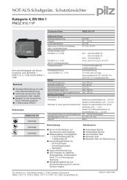
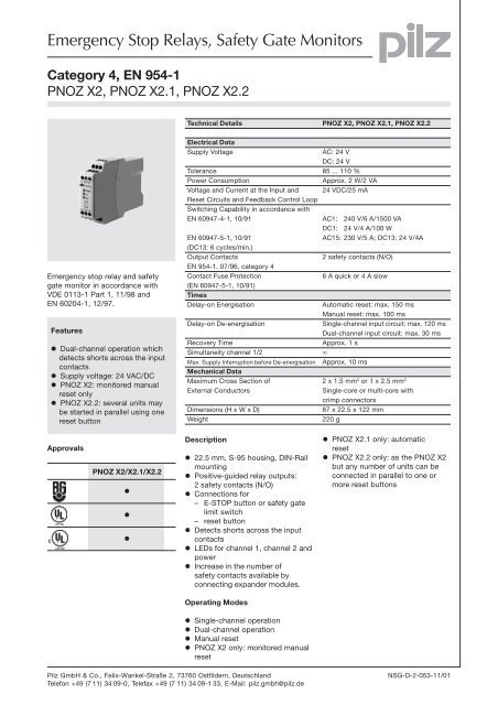
<strong>Emergency</strong> <strong>Stop</strong> <strong>Relays</strong>, <strong>Safety</strong> <strong>Gate</strong> <strong>Monitors</strong><br />
Category 4, EN 954-1<br />
PNOZ X2, PNOZ X2.1, PNOZ X2.2<br />
<strong>Emergency</strong> stop relay and safety<br />
gate monitor in accordance with<br />
VDE 0113-1 Part 1, 11/98 and<br />
EN 60204-1, 12/97.<br />
Features<br />
l Dual-channel operation which<br />
detects shorts across the input<br />
contacts<br />
l Supply voltage: 24 VAC/DC<br />
l PNOZ X2: monitored manual<br />
reset only<br />
l PNOZ X2.2: several units may<br />
be started in parallel using one<br />
reset button<br />
Approvals<br />
PNOZ X2/X2.1/X2.2<br />
l<br />
l<br />
l<br />
Technical Details PNOZ X2, PNOZ X2.1, PNOZ X2.2<br />
Electrical Data<br />
Supply Voltage AC: 24 V<br />
DC: 24 V<br />
Tolerance 85 ... 110 %<br />
Power Consumption Approx. 2 W/2 VA<br />
Voltage and Current at the Input and 24 VDC/25 mA<br />
Reset Circuits and Feedback Control Loop<br />
Switching Capability in accordance with<br />
EN 60947-4-1, 10/91 AC1: 240 V/6 A/1500 VA<br />
DC1: 24 V/4 A/100 W<br />
EN 60947-5-1, 10/91 AC15: 230 V/5 A; DC13: 24 V/4A<br />
(DC13: 6 cycles/min.)<br />
Output Contacts 2 safety contacts (N/O)<br />
EN 954-1, 07/96, category 4<br />
Contact Fuse Protection 6 A quick or 4 A slow<br />
(EN 60947-5-1, 10/91)<br />
Times<br />
Delay-on Energisation Automatic reset: max. 150 ms<br />
Manual reset: max. 100 ms<br />
Delay-on De-energisation Single-channel input circuit: max. 120 ms<br />
Dual-channel input circuit: max. 30 ms<br />
Recovery Time Approx. 1 s<br />
Simultaneity channel 1/2 ¥<br />
Max. Supply Interruption before De-energisation Approx. 10 ms<br />
Mechanical Data<br />
Maximum Cross Section of 2 x 1.5 mm 2 or 1 x 2.5 mm 2<br />
External Conductors Single-core or multi-core with<br />
crimp connectors<br />
Dimensions (H x W x D) 87 x 22.5 x 122 mm<br />
Weight 220 g<br />
Description<br />
l 22.5 mm, S-95 housing, DIN-Rail<br />
mounting<br />
l Positive-guided relay outputs:<br />
2 safety contacts (N/O)<br />
l Connections for<br />
– E-STOP button or safety gate<br />
limit switch<br />
– reset button<br />
l Detects shorts across the input<br />
contacts<br />
l LEDs for channel 1, channel 2 and<br />
power<br />
l Increase in the number of<br />
safety contacts available by<br />
connecting expander modules.<br />
Operating Modes<br />
l Single-channel operation<br />
l Dual-channel operation<br />
l Manual reset<br />
l PNOZ X2 only: monitored manual<br />
reset<br />
l PNOZ X2.1 only: automatic<br />
reset<br />
l PNOZ X2.2 only: as the PNOZ X2<br />
but any number of units can be<br />
connected in parallel to one or<br />
more reset buttons<br />
Pilz GmbH & Co., Felix-Wankel-Straße 2, 73760 Ostfildern, Deutschland NSG-D-2-053-11/01<br />
Telefon +49 (7 11) 34 09-0, Telefax +49 (7 11) 34 09-1 33, E-Mail: pilz.gmbh@pilz.de<br />
1<br />
1-1
1<br />
<strong>Emergency</strong> <strong>Stop</strong> <strong>Relays</strong>, <strong>Safety</strong> <strong>Gate</strong> <strong>Monitors</strong><br />
Category 4, EN 954-1<br />
PNOZ X2, PNOZ X2.1, PNOZ X2.2<br />
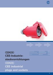
Internal Wiring Diagram<br />
– PNOZ X2, PNOZ X2.1<br />
– PNOZ X2.2<br />
External Wiring<br />
l Example 1<br />
Single-channel E-STOP wiring with<br />
monitored manual reset, delay-on<br />
de-energisation: max. 100 ms<br />
S1<br />
UB<br />
(L+)<br />
A1<br />
S11 S21<br />
S3<br />
S33<br />
S12 S22 S34<br />
A1 (L+) A2 (L-)<br />
UB<br />
UB<br />
A1 (L+) A2 (L-)<br />
Reset Input<br />
circuit circuit<br />
<strong>Safety</strong><br />
contacts<br />
S34 S33 S11 S12 13 23<br />
Start<br />
Unit<br />
K1<br />
Start<br />
Unit<br />
S22 S21<br />
Input circuit<br />
K2<br />
Reset<br />
circuit<br />
Input<br />
circuit<br />
<strong>Safety</strong><br />
contacts<br />
S33 S34 S11 S12 13 23<br />
K3<br />
Start<br />
Unit<br />
K3<br />
K1<br />
Start<br />
Unit<br />
S22 S21<br />
Input circuit<br />
l Example 2<br />
Dual-channel E-STOP wiring with<br />
monitored manual reset.<br />
S1<br />
14<br />
K2<br />
24<br />
14<br />
24<br />
S11 S21<br />
S3<br />
S33<br />
S12 S22 S34<br />
l Example 3<br />
PNOZ X2.1 only: dual-channel<br />
E-STOP wiring with automatic reset.<br />
S1<br />
S11 S21 S33<br />
S12 S22 S34<br />
l Example 4<br />
Dual-channel safety gate control<br />
through forced-contact limit switches<br />
with position monitoring.<br />
S11<br />
S22<br />
S1<br />
S12<br />
S21<br />
S2<br />
l Example 5<br />
PNOZ X2.1 only: dual-channel safety<br />
gate control with automatic reset.<br />
Pilz GmbH & Co., Felix-Wankel-Straße 2, 73760 Ostfildern, Deutschland NSG-D-2-053-11/01<br />
Telefon +49 (7 11) 34 09-0, Telefax +49 (7 11) 34 09-1 33, E-Mail: pilz.gmbh@pilz.de<br />
S11<br />
S22<br />
S1<br />
S12<br />
S21<br />
S2<br />
S3<br />
S33<br />
S34<br />
S33<br />
S34
<strong>Emergency</strong> <strong>Stop</strong> <strong>Relays</strong>, <strong>Safety</strong> <strong>Gate</strong> <strong>Monitors</strong><br />
Category 4, EN 954-1<br />
PNOZ X2, PNOZ X2.1, PNOZ X2.2<br />
l Example 6<br />
PNOZ X2.2 only: dual-channel<br />
E-STOP wiring where units can be<br />
started in parallel using one reset<br />
button.<br />
– Key<br />
+24 V DC<br />
0 V<br />
S1/2: E-STOP or safety gate switch<br />
S3: Reset button<br />
1L1<br />
1L2<br />
S1<br />
Switch operated<br />
<strong>Gate</strong> open<br />
<strong>Gate</strong> closed<br />
l Increase in safety contacts<br />
The number of output contacts can<br />
be increased by using expander<br />
modules or relays/contactors with<br />
positive-guided contacts.<br />
K4 K5<br />
S33 S34<br />
13 23 24<br />
A1 S33 S34<br />
S11 S12 A2<br />
14 S21 S22<br />
13<br />
14<br />
K4 K5<br />
S1<br />
13 23 24<br />
A1 S33 S34<br />
S11 S12 A2<br />
14 S21 S22<br />
S1<br />
13 23 24<br />
A1 S33 S34<br />
S11 S12 A2<br />
14 S21 S22<br />
Pilz GmbH & Co., Felix-Wankel-Straße 2, 73760 Ostfildern, Deutschland NSG-D-2-053-11/01<br />
Telefon +49 (7 11) 34 09-0, Telefax +49 (7 11) 34 09-1 33, E-Mail: pilz.gmbh@pilz.de<br />
S3<br />
1<br />
1-3
1<br />
<strong>Emergency</strong> <strong>Stop</strong> <strong>Relays</strong>, <strong>Safety</strong> <strong>Gate</strong> <strong>Monitors</strong><br />
Category 4, EN 954-1<br />
PNOZ X2, PNOZ X2.1, PNOZ X2.2<br />
General Technical Data<br />
Unless stated otherwise in the technical details for the specific unit<br />
Electrical Data<br />
Frequency Range AC 50 ... 60 Hz<br />
Residual Ripple DC 160 %<br />
Contact Material AgSnO 2<br />
Continuous Duty 100 %<br />
Environmental Data<br />
EMC EN 50081-1, 01/92, EN 50082-2, 03/95<br />
Vibration in accordance with Frequency: 10 ... 55 Hz,<br />
EN 60068-2-6, 04/95 Amplitude: 0.35 mm<br />
Climatic Suitability DIN IEC 60068-2-3, 12/86<br />
Airgap Creepage DIN VDE 0110 part 1, 04/97<br />
Ambient Temperature -10 ... +55 °C<br />
Storage Temperature -40 ... +85 °C<br />
Mechanical Data<br />
Torque Setting on Connection Terminals 0.6 Nm (screws)<br />
Mounting Position Any<br />
Housing Material Thermoplast Noryl SE 100<br />
Protection Mounting: IP 54<br />
Housing: IP 40<br />
Terminal Range: IP 20<br />
The units were tested in accordance with the relevant standards current at<br />
the time of development.<br />
Order References<br />
Type U B Order No.<br />
PNOZ X2 24 V AC/DC 774 303<br />
PNOZ X2.1 24 V AC/DC 774 306<br />
PNOZ X2.2 24 V AC/DC 774 607<br />
Pilz GmbH & Co., Felix-Wankel-Straße 2, 73760 Ostfildern, Deutschland NSG-D-2-053-11/01<br />
Telefon +49 (7 11) 34 09-0, Telefax +49 (7 11) 34 09-1 33, E-Mail: pilz.gmbh@pilz.de