MAPS-010164 - M/A-COM Technology Solutions
MAPS-010164 - M/A-COM Technology Solutions
MAPS-010164 - M/A-COM Technology Solutions

You also want an ePaper? Increase the reach of your titles
YUMPU automatically turns print PDFs into web optimized ePapers that Google loves.
2<br />
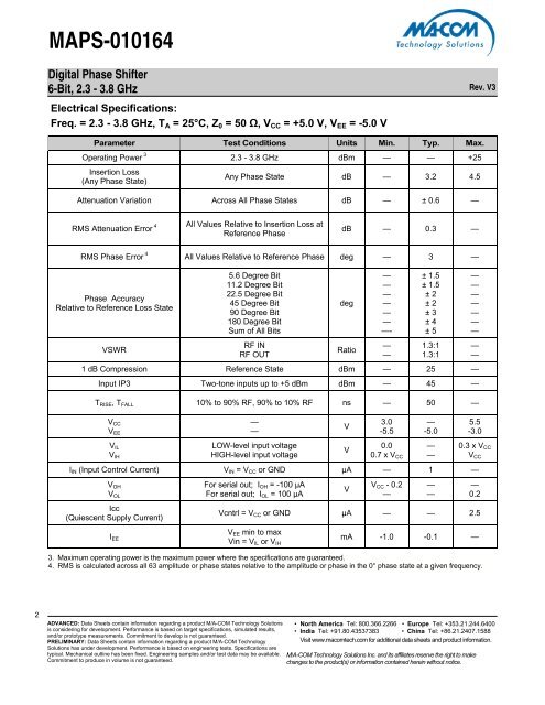
<strong>MAPS</strong>-<strong>010164</strong><br />
Digital Phase Shifter<br />
6-Bit, 2.3 - 3.8 GHz<br />
Electrical Specifications:<br />
Freq. = 2.3 - 3.8 GHz, TA = 25°C, Z0 = 50 Ω, VCC = +5.0 V, VEE = -5.0 V<br />
Parameter Test Conditions Units Min. Typ. Max.<br />
Operating Power 3 2.3 - 3.8 GHz dBm — — +25<br />
Insertion Loss<br />
(Any Phase State)<br />
Any Phase State dB — 3.2 4.5<br />
Attenuation Variation Across All Phase States dB — ± 0.6 —<br />
RMS Attenuation Error 4<br />
All Values Relative to Insertion Loss at<br />
Reference Phase<br />
ADVANCED: Data Sheets contain information regarding a product M/A-<strong>COM</strong> <strong>Technology</strong> <strong>Solutions</strong><br />
is considering for development. Performance is based on target specifications, simulated results,<br />
and/or prototype measurements. Commitment to develop is not guaranteed.<br />
PRELIMINARY: Data Sheets contain information regarding a product M/A-<strong>COM</strong> <strong>Technology</strong><br />
<strong>Solutions</strong> has under development. Performance is based on engineering tests. Specifications are<br />
typical. Mechanical outline has been fixed. Engineering samples and/or test data may be available.<br />
Commitment to produce in volume is not guaranteed.<br />
dB — 0.3 —<br />
RMS Phase Error 4 All Values Relative to Reference Phase deg — 3 —<br />
Phase Accuracy<br />
Relative to Reference Loss State<br />
VSWR<br />
5.6 Degree Bit<br />
11.2 Degree Bit<br />
22.5 Degree Bit<br />
45 Degree Bit<br />
90 Degree Bit<br />
180 Degree Bit<br />
Sum of All Bits<br />
RF IN<br />
RF OUT<br />
deg<br />
Ratio<br />
—<br />
—<br />
—<br />
—<br />
—<br />
—<br />
—-<br />
—<br />
—<br />
± 1.5<br />
± 1.5<br />
± 2<br />
± 2<br />
± 3<br />
± 4<br />
± 5<br />
1.3:1<br />
1.3:1<br />
1 dB Compression Reference State dBm — 25 —<br />
Input IP3 Two-tone inputs up to +5 dBm dBm — 45 —<br />
TRISE, TFALL 10% to 90% RF, 90% to 10% RF ns — 50 —<br />
VCC<br />
VEE<br />
VIL<br />
VIH<br />
—<br />
—<br />
LOW-level input voltage<br />
HIGH-level input voltage<br />
V<br />
V<br />
3.0<br />
-5.5<br />
0.0<br />
0.7 x VCC<br />
lIN (Input Control Current) VIN = VCC or GND µA — 1 —<br />
VOH<br />
VOL<br />
Icc<br />
(Quiescent Supply Current)<br />
IEE<br />
For serial out; IOH = -100 µA<br />
For serial out; IOL = 100 µA<br />
V<br />
VCC - 0.2<br />
—<br />
—<br />
-5.0<br />
—<br />
—<br />
—<br />
—<br />
Rev. V3<br />
• North America Tel: 800.366.2266 • Europe Tel: +353.21.244.6400<br />
• India Tel: +91.80.43537383 • China Tel: +86.21.2407.1588<br />
Visit www.macomtech.com for additional data sheets and product information.<br />
M/A-<strong>COM</strong> <strong>Technology</strong> <strong>Solutions</strong> Inc. and its affiliates reserve the right to make<br />
changes to the product(s) or information contained herein without notice.<br />
—<br />
—<br />
—<br />
—<br />
—<br />
—<br />
—<br />
—<br />
—<br />
5.5<br />
-3.0<br />
0.3 x VCC<br />
Vcntrl = VCC or GND µA — — 2.5<br />
VEE min to max<br />
Vin = VIL or VIH<br />
VCC<br />
—<br />
0.2<br />
mA -1.0 -0.1 —<br />
3. Maximum operating power is the maximum power where the specifications are guaranteed.<br />
4. RMS is calculated across all 63 amplitude or phase states relative to the amplitude or phase in the 0° phase state at a given frequency.