AT90-1413 - M/A-COM Technology Solutions
AT90-1413 - M/A-COM Technology Solutions
AT90-1413 - M/A-COM Technology Solutions

You also want an ePaper? Increase the reach of your titles
YUMPU automatically turns print PDFs into web optimized ePapers that Google loves.
1<br />
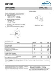
<strong>AT90</strong>-<strong>1413</strong><br />
Digital Attenuator<br />
15 dB, 4-Bit, TTL Driver, DC-4.0 GHz<br />
Features<br />
• Attenuation: 1 dB Steps to 15 dB<br />
• Single Positive Supply<br />
• Contains Internal DC to DC Converter<br />
• Integral TTL Driver<br />
• 50 Ohm Impedance<br />
• Test Boards Available<br />
• Tape and Reel Packaging Available<br />
• CSP-1 Package<br />
Description<br />
M/A-<strong>COM</strong>’s <strong>AT90</strong>-<strong>1413</strong> is a GaAs FET 4-Bit digital<br />
attenuator with integral driver. Step size is 1 dB providing<br />
a 15 dB attenuation range. This device is in<br />
an PQFN plastic surface mount package. The<br />
<strong>AT90</strong>-<strong>1413</strong> is suited for single supply applications<br />
where accuracy, fast speed, low power consumption<br />
and low costs are required. For dual supply designs<br />
without switching noise, use <strong>AT90</strong>-0413.<br />
Ordering Information<br />
Part Number Package<br />
<strong>AT90</strong>-<strong>1413</strong> Bulk Packaging<br />
<strong>AT90</strong>-<strong>1413</strong>TR 1000 piece reel<br />
<strong>AT90</strong>-<strong>1413</strong>-TB Sample Test Board<br />
Note: Reference Application Note M513 for reel size<br />
information.<br />
ADVANCED: Data Sheets contain information regarding a product M/A-<strong>COM</strong> <strong>Technology</strong> <strong>Solutions</strong><br />
is considering for development. Performance is based on target specifications, simulated results,<br />
and/or prototype measurements. Commitment to develop is not guaranteed.<br />
PRELIMINARY: Data Sheets contain information regarding a product M/A-<strong>COM</strong> <strong>Technology</strong><br />
<strong>Solutions</strong> has under development. Performance is based on engineering tests. Specifications are<br />
typical. Mechanical outline has been fixed. Engineering samples and/or test data may be available.<br />
Commitment to produce in volume is not guaranteed.<br />
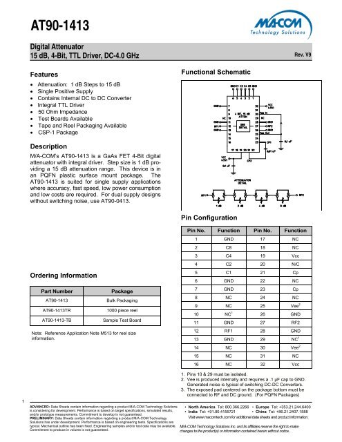
Functional Schematic<br />
Pin Configuration<br />
• North America Tel: 800.366.2266 • Europe Tel: +353.21.244.6400<br />
• India Tel: +91.80.4155721 • China Tel: +86.21.2407.1588<br />
Visit www.macomtech.com for additional data sheets and product information.<br />
M/A-<strong>COM</strong> <strong>Technology</strong> <strong>Solutions</strong> Inc. and its affiliates reserve the right to make<br />
changes to the product(s) or information contained herein without notice.<br />
Rev. V9<br />
Pin No. Function Pin No. Function<br />
1 GND 17 NC<br />
2 C8 18 NC<br />
3 C4 19 Vcc<br />
4 C2 20 N/C<br />
5 C1 21 Cp<br />
6 GND 22 NC<br />
7 GND 23 Cp<br />
8 NC 24 NC<br />
9 NC 25 Vee 2<br />
10 NC 1 26 GND<br />
11 GND 27 RF2<br />
12 RF1 28 GND<br />
13 GND 29 NC 1<br />
14 NC 30 Vee 2<br />
15 NC 31 NC<br />
16 NC 32 Vcc<br />
1. Pins 10 & 29 must be isolated.<br />
2. Vee is produced internally and requires a .1 µF cap to GND.<br />
Generated noise is typical of switching DC-DC Converters.<br />
3. The exposed pad centered on the package bottom must be<br />
connected to RF and DC ground. (For PQFN Packages)
2<br />
<strong>AT90</strong>-<strong>1413</strong><br />
Digital Attenuator<br />
15 dB, 4-Bit, TTL Driver, DC-4.0 GHz<br />
Electrical Specifications: TA = 25°C, Z0 = 50Ω<br />
Parameter Test Conditions Frequency Units Min Typ Max<br />
Insertion Loss —<br />
DC-2.5 GHz<br />
DC-4.0 GHz<br />
Attenuation<br />
Accuracy<br />
ADVANCED: Data Sheets contain information regarding a product M/A-<strong>COM</strong> <strong>Technology</strong> <strong>Solutions</strong><br />
is considering for development. Performance is based on target specifications, simulated results,<br />
and/or prototype measurements. Commitment to develop is not guaranteed.<br />
PRELIMINARY: Data Sheets contain information regarding a product M/A-<strong>COM</strong> <strong>Technology</strong><br />
<strong>Solutions</strong> has under development. Performance is based on engineering tests. Specifications are<br />
typical. Mechanical outline has been fixed. Engineering samples and/or test data may be available.<br />
Commitment to produce in volume is not guaranteed.<br />
DC-2.5 GHz<br />
DC-4.0 GHz<br />
VSWR Full Attenuation Range DC-2.5 GHz<br />
DC-4.0 GHz<br />
Switching Speed 50% Cntl to 90%/10% RF<br />
—<br />
10% to 90% or 90% to 10%<br />
—<br />
1 dB Compression —<br />
50 MHz<br />
0.5-4.0 GHz<br />
Input IP3<br />
50 MHz<br />
0.5-4.0 GHz<br />
dB<br />
dB<br />
dB<br />
dB<br />
Ratio<br />
Ratio<br />
ns<br />
ns<br />
dBm<br />
dBm<br />
dBm<br />
dBm<br />
—<br />
—<br />
—<br />
—<br />
—<br />
—<br />
—<br />
—<br />
—<br />
—<br />
—<br />
—<br />
2.0<br />
2.5<br />
—<br />
—<br />
1.5:1<br />
1.8:1<br />
75<br />
20<br />
+21<br />
+29<br />
+35<br />
+48<br />
2.5<br />
3.0<br />
• North America Tel: 800.366.2266 • Europe Tel: +353.21.244.6400<br />
• India Tel: +91.80.4155721 • China Tel: +86.21.2407.1588<br />
Visit www.macomtech.com for additional data sheets and product information.<br />
M/A-<strong>COM</strong> <strong>Technology</strong> <strong>Solutions</strong> Inc. and its affiliates reserve the right to make<br />
changes to the product(s) or information contained herein without notice.<br />
Rev. V9<br />
±(0.3+4% of atten setting)<br />
±(0.3+6% of atten setting)<br />
Vcc —<br />
— V 4.75 5.0 5.25<br />
VIL<br />
VIH<br />
Individual Bits or<br />
Combination of Bits<br />
Two-tone Inputs up to +5 dBm<br />
LOW-level input voltage<br />
HIGH-level input voltage<br />
lin (Input Leakage Current) Vin = VCC or GND<br />
— uA -1.0 — 1.0<br />
Icc 4 Vcc min to max, Logic “0” or “1” — mA — 6 10<br />
Turn-on Current 5 For guaranteed start-up — mA — — 125<br />
ΔIcc<br />
(Additional Supply Current<br />
Per TTL Input Pin)<br />
—<br />
—<br />
VCC = Max, Vcntrl = VCC - 2.1 V — mA — — 1.0<br />
Switching Noise Generated from<br />
DC-DC Converter with<br />
recommended capacitors<br />
V<br />
V<br />
0.0<br />
2.0<br />
—<br />
—<br />
1.8:1<br />
2.0:1<br />
150<br />
50<br />
—<br />
—<br />
—<br />
—<br />
0.8<br />
5.0<br />
3.5 MHz dBm — -93 —<br />
Thermal Resistance θjc — — °C/W — 15 —<br />
4. During turn-on, the device requires an initial start up current (Icc)<br />
specified as “Turn-on Current”. Once operational, Icc will drop to the<br />
specified levels.<br />
5. The DC-DC converter is guaranteed to start in 100 µs as long as the<br />
power supplies have the maximum turn-on current available for startup.<br />
Absolute Maximum Ratings 6,7<br />
Parameter Absolute Maximum<br />
Max. Input Power<br />
0.05 GHz<br />
0.5 - 4.0 GHz<br />
VCC<br />
+27 dBm<br />
+34 dBm<br />
-0.5V ≤ VCC ≤ +6.0V<br />
Vin 8 -0.5V ≤ Vin ≤ VCC + 0.5V<br />
Operating Temperature -40ºC to +85ºC<br />
Storage Temperature -65ºC to +125ºC<br />
6. Exceeding any one or combination of these limits may cause<br />
permanent damage to this device.<br />
7. M/A-<strong>COM</strong> does not recommend sustained operation near<br />
these survivability limits.<br />
8. Standard CMOS TTL interface, latch-up will occur if logic signal<br />
is applied prior to power supply.<br />
Recommended PCB Configuration 9<br />
9. Application Note S2083 is available on line at www.macom.com
3<br />
<strong>AT90</strong>-<strong>1413</strong><br />
Digital Attenuator<br />
15 dB, 4-Bit, TTL Driver, DC-4.0 GHz<br />
Handling Procedures<br />
Please observe the following precautions to avoid<br />
damage:<br />
Static Sensitivity<br />
Gallium Arsenide Integrated Circuits are sensitive<br />
to electrostatic discharge (ESD) and can be<br />
damaged by static electricity. Proper ESD control<br />
techniques should be used when handling these<br />
devices.<br />
Moisture Sensitivity<br />
The MSL rating for this part is defined as Level 2<br />
per IPC/JEDEC J-STD-020. Parts shall be stored<br />
and/or baked as required for MSL Level 2 parts.<br />
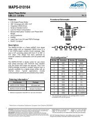
Typical Performance Curves<br />
Insertion Loss<br />
Attenuation (dB)<br />
3.00<br />
2.50<br />
2.00<br />
1.50<br />
1.0 0<br />
0 500 1000 1500 2000 2500 3000 3500 4000<br />
Fre que ncy (MHz)<br />
ADVANCED: Data Sheets contain information regarding a product M/A-<strong>COM</strong> <strong>Technology</strong> <strong>Solutions</strong><br />
is considering for development. Performance is based on target specifications, simulated results,<br />
and/or prototype measurements. Commitment to develop is not guaranteed.<br />
PRELIMINARY: Data Sheets contain information regarding a product M/A-<strong>COM</strong> <strong>Technology</strong><br />
<strong>Solutions</strong> has under development. Performance is based on engineering tests. Specifications are<br />
typical. Mechanical outline has been fixed. Engineering samples and/or test data may be available.<br />
Commitment to produce in volume is not guaranteed.<br />
Truth Table (Digital Attenuator)<br />
C8 C4 C2 C1 Attenuation<br />
0 0 0 0 Loss, Reference<br />
0 0 0 1 1.0 dB<br />
0 0 1 0 2.0 dB<br />
0 1 0 0 4.0 dB<br />
1 0 0 0 8.0 dB<br />
1 1 1 1 15.0 dB<br />
0 = TTL Low; 1 = TTL High<br />
VSWR @ Insertion Loss<br />
Attenuation Error, 1 dB Bit Attenuation Error, 2 dB Bit<br />
Attenuation (dB)<br />
0.30<br />
0.20<br />
0.10<br />
0.00<br />
-0.10<br />
-0.20<br />
-0.30<br />
0 500 1000 1500 2000 2500 3000 3500 4000<br />
Frequency (MHz)<br />
VSWR<br />
Attenuation (dB)<br />
1.6 0<br />
1.4 0<br />
1.2 0<br />
RF In RF Out<br />
• North America Tel: 800.366.2266 • Europe Tel: +353.21.244.6400<br />
• India Tel: +91.80.4155721 • China Tel: +86.21.2407.1588<br />
Visit www.macomtech.com for additional data sheets and product information.<br />
M/A-<strong>COM</strong> <strong>Technology</strong> <strong>Solutions</strong> Inc. and its affiliates reserve the right to make<br />
changes to the product(s) or information contained herein without notice.<br />
Rev. V9<br />
1.0 0<br />
0 500 1000 1500 2000 2500 3000 3500 4000<br />
0.30<br />
0.20<br />
0.10<br />
0.00<br />
-0.10<br />
-0.20<br />
Fre que ncy (MHz)<br />
-0.30<br />
0 500 1000 1500 2000 2500 3000 3500 4000<br />
Fre que ncy (MHz)
4<br />
<strong>AT90</strong>-<strong>1413</strong><br />
Digital Attenuator<br />
15 dB, 4-Bit, TTL Driver, DC-4.0 GHz<br />
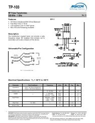
Typical Performance Curves<br />
Attenuation Error, 4 dB Bit<br />
Attenuation (dB)<br />
0.60<br />
0.40<br />
0.20<br />
0.00<br />
-0.20<br />
0 500 1000 1500 2000 2500 3000 3500 4000<br />
Fre que ncy (MHz)<br />
ADVANCED: Data Sheets contain information regarding a product M/A-<strong>COM</strong> <strong>Technology</strong> <strong>Solutions</strong><br />
is considering for development. Performance is based on target specifications, simulated results,<br />
and/or prototype measurements. Commitment to develop is not guaranteed.<br />
PRELIMINARY: Data Sheets contain information regarding a product M/A-<strong>COM</strong> <strong>Technology</strong><br />
<strong>Solutions</strong> has under development. Performance is based on engineering tests. Specifications are<br />
typical. Mechanical outline has been fixed. Engineering samples and/or test data may be available.<br />
Commitment to produce in volume is not guaranteed.<br />
Attenuation Error, 8 dB Bit<br />
Attenuation Error, Max. Attenuation VSWR, 1 dB Bit<br />
Attenuation (dB)<br />
VSWR, 2 dB Bit VSWR, 4 dB Bit<br />
VSWR<br />
-0.20<br />
-0.40<br />
0 500 1000 1500 2000 2500 3000 3500 4000<br />
1.6 0<br />
1.4 0<br />
1.2 0<br />
0.40<br />
0.20<br />
0.00<br />
Fre que ncy (MHz)<br />
RF In RF Out<br />
1.0 0<br />
0 500 1000 1500 2000 2500 3000 3500 4000<br />
Fre que ncy (MHz)<br />
Attenuation (dB)<br />
VSWR<br />
VSWR<br />
0.20<br />
0.00<br />
-0.20<br />
-0.40<br />
• North America Tel: 800.366.2266 • Europe Tel: +353.21.244.6400<br />
• India Tel: +91.80.4155721 • China Tel: +86.21.2407.1588<br />
Visit www.macomtech.com for additional data sheets and product information.<br />
M/A-<strong>COM</strong> <strong>Technology</strong> <strong>Solutions</strong> Inc. and its affiliates reserve the right to make<br />
changes to the product(s) or information contained herein without notice.<br />
Rev. V9<br />
-0.60<br />
0 500 1000 1500 2000 2500 3000 3500 4000<br />
1.6 0<br />
1.4 0<br />
1.2 0<br />
Fre que ncy (MHz)<br />
RF In RF Out<br />
1.0 0<br />
0 500 1000 1500 2000 2500 3000 3500 4000<br />
1.6 0<br />
1.4 0<br />
1.2 0<br />
Fre que ncy (MHz)<br />
RF In RF Out<br />
1.0 0<br />
0 500 1000 1500 2000 2500 3000 3500 4000<br />
Fre que ncy (MHz)
5<br />
<strong>AT90</strong>-<strong>1413</strong><br />
Digital Attenuator<br />
15 dB, 4-Bit, TTL Driver, DC-4.0 GHz<br />
Typical Performance Curves<br />
VSWR, 8 dB Bit<br />
VSWR<br />
1.6 0<br />
1.4 0<br />
1.2 0<br />
RF In RF Out<br />
1.0 0<br />
0 500 1000 1500 2000 2500 3000 3500 4000<br />
Fre que ncy (MHz)<br />
CSP-1, 4 x 6 mm, 32-lead PQFN †<br />
†<br />
Reference Application Note M538 for lead-free solder reflow<br />
recommendations.<br />
ADVANCED: Data Sheets contain information regarding a product M/A-<strong>COM</strong> <strong>Technology</strong> <strong>Solutions</strong><br />
is considering for development. Performance is based on target specifications, simulated results,<br />
and/or prototype measurements. Commitment to develop is not guaranteed.<br />
PRELIMINARY: Data Sheets contain information regarding a product M/A-<strong>COM</strong> <strong>Technology</strong><br />
<strong>Solutions</strong> has under development. Performance is based on engineering tests. Specifications are<br />
typical. Mechanical outline has been fixed. Engineering samples and/or test data may be available.<br />
Commitment to produce in volume is not guaranteed.<br />
VSWR, Maximum Attenuation<br />
VSWR<br />
1.6 0<br />
1.4 0<br />
1.2 0<br />
1.0 0<br />
RF In RF Out<br />
• North America Tel: 800.366.2266 • Europe Tel: +353.21.244.6400<br />
• India Tel: +91.80.4155721 • China Tel: +86.21.2407.1588<br />
Visit www.macomtech.com for additional data sheets and product information.<br />
M/A-<strong>COM</strong> <strong>Technology</strong> <strong>Solutions</strong> Inc. and its affiliates reserve the right to make<br />
changes to the product(s) or information contained herein without notice.<br />
Rev. V9<br />
0 500 1000 1500 2000 2500 3000 3500 4000<br />
Fre que ncy (MHz)