Maximizing DAC Performance for Every Budget - ESS Technology, Inc.
Maximizing DAC Performance for Every Budget - ESS Technology, Inc.
Maximizing DAC Performance for Every Budget - ESS Technology, Inc.

You also want an ePaper? Increase the reach of your titles
YUMPU automatically turns print PDFs into web optimized ePapers that Google loves.
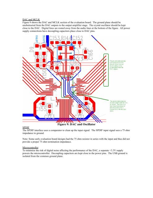
<strong>DAC</strong> and MCLK<br />
Figure 9 shows the <strong>DAC</strong> and MCLK section of the evaluation board. The ground plane should be<br />
unobstructed from the <strong>DAC</strong> outputs to the output amplifier stage. The crystal oscillator should be kept<br />
close to the <strong>DAC</strong>. Digital lines are routed away from the audio lines at the bottom of the figure. All power<br />
supply connections have decoupling capacitors place close to <strong>DAC</strong> pins.<br />
Figure 9: <strong>DAC</strong> and Oscillator<br />
SPDIF<br />
The SPDIF interface uses a comparator to clean up the input signal. The SPDIF input signal sees a 75 ohm<br />
impedance to ground.<br />
Note: Some early evaluation board designs had the 75 ohm resistor in series with the input and thus did not<br />
provide a proper 75 ohm termination impedance.<br />
Microcontroller<br />
To minimize the risk of digital noise affecting the per<strong>for</strong>mance of the <strong>DAC</strong>, a separate +3.3V supply<br />
powers the microcontroller. Decoupling capacitors are kept close to the power pins. The USB ground is<br />
isolated from the common ground plane.