TTC Timmler Technology TTC Active and Passive Chilled Beams ...
TTC Timmler Technology TTC Active and Passive Chilled Beams ...
TTC Timmler Technology TTC Active and Passive Chilled Beams ...

Create successful ePaper yourself
Turn your PDF publications into a flip-book with our unique Google optimized e-Paper software.
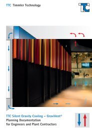
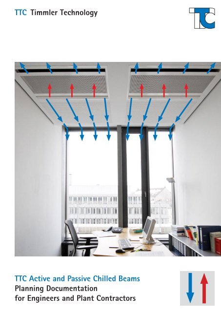
<strong>TTC</strong> <strong>Timmler</strong> <strong>Technology</strong><br />
<strong>TTC</strong> <strong>Active</strong> <strong>and</strong> <strong>Passive</strong> <strong>Chilled</strong> <strong>Beams</strong><br />
Planning Documentation<br />
for Engineers <strong>and</strong> Plant Contractors
Contents | Features<br />
<strong>Active</strong> <strong>TTC</strong> <strong>Chilled</strong> <strong>Beams</strong><br />
2<br />
i<br />
General Information Pages 4–7<br />
· Order key for <strong>TTC</strong> <strong>Chilled</strong> <strong>Beams</strong><br />
· Notes in air conditioning<br />
· Diagram of an air conditioned space<br />
· Controls <strong>and</strong> schematic diagram of <strong>TTC</strong><br />
chilled beams<br />
<strong>TTC</strong> Cassette <strong>Chilled</strong> Beam ACBLQ Pages 8–9<br />
· Installation in panelled ceilings<br />
· White casing (coating similar to RAL 9010)<br />
· Length <strong>and</strong> width (592 x 592 mm) · 3 capacity levels<br />
· Height 225 mm, side supply air<br />
·<br />
connection<br />
Capacity at ∆m = 10 K, air volume flow<br />
· Air adjustment valve as st<strong>and</strong>ard 80 m³⁄h (4-sided air discharge); capacity<br />
· Air discharge on 4 sides, individually level 9<br />
adjustable<br />
Cooling capacity Q˙ K(tot) = 500 W<br />
· Recirculating air intake through<br />
perforated cover<br />
Sound pressure level < 25 dB (A)<br />
<strong>TTC</strong> <strong>Chilled</strong> Beam ACBLZ Pages 10–11<br />
· Installation preferably in panelled ceilings Capacity at ∆m = 10 K, air volume flow<br />
· Low height 146 mm, top or end supply 40 m³⁄h (2-sided air discharge); capacity<br />
air connection<br />
level 1, setting 5<br />
· Air adjustment valve as st<strong>and</strong>ard Cooling capacity Q˙ K(tot) = 500 W<br />
· Air discharge 2-sided<br />
Sound pressure level < 25 dB (A) for a<br />
· Power level adjustable via the air<br />
adjustment valve<br />
· White casing (coating similar to RAL 9010)<br />
chilled beam length of 12 dm<br />
<strong>TTC</strong> <strong>Chilled</strong> Beam ACBLA Pages 12–13<br />
· Installation preferably underneath the · White casing (coating similar to RAL 9010)<br />
ceiling<br />
· Built-in air passage grill<br />
· 4 capacity levels<br />
· Length ≈ 1200/1800/2400 mm<br />
Capacity at ∆m = 10 K, air volume flow<br />
· Height 171 mm, Width 364 mm<br />
60 m³⁄h (2-sided air discharge); capacity<br />
· Recirculating air intake through<br />
level 8<br />
perforated cover<br />
Cooling capacity q˙ K(spec) = 540 W/m<br />
· Supply air discharge on the side at the top Sound pressure level < 25 dB (A) for a<br />
· Supply air inlet on the end<br />
chilled beam length of 24 dm<br />
<strong>TTC</strong> <strong>Chilled</strong> Beam ACBLE Pages 14–17<br />
· Installation preferably in panelled ceilings<br />
· Built-in air passage grill<br />
· Length ≈ 1200/1800/2400 mm<br />
· Height 165 mm, Width 592 mm<br />
· Recirculating air intake through<br />
perforated cover<br />
· Supply air discharge horizontally underneath<br />
the ceiling<br />
· Supply air inlet on the end<br />
· White casing (coating similar to RAL 9010)<br />
· 4 capacity levels<br />
Capacity at ∆m = 10 K, air volume flow<br />
60 m³⁄h (2-sided air discharge); capacity<br />
level 8<br />
Cooling capacity q˙ K(spec) = 540 W/m<br />
Sound pressure level < 25 dB (A) for a<br />
chilled beam length of 24 dm<br />
<strong>TTC</strong> <strong>Chilled</strong> Beam ACBLO Pages 18–19<br />
· Installation preferably in panelled ceilings · White casing (coating similar to RAL 9010)<br />
· Cover can be folded up or down<br />
· 3 capacity levels<br />
· Length ≈ 1200/1800/2400 mm<br />
Capacity at ∆m = 10 K, air volume flow<br />
· Height 255 mm, width 595 mm<br />
50 m³⁄h (2-sided air discharge); capacity<br />
· Recirculating air inlet at the top<br />
level 9<br />
· Supply air discharge horizontally under- Cooling capacity q˙ K(spec) = 835W/m<br />
neath the ceiling<br />
Sound pressure level < 25 dB (A) for a<br />
· Supply air inlet on the end<br />
chilled beam length of 24 dm<br />
Subject to technical changes · Issued 10/2010
Subject to technical changes · Issued 10/2010<br />
Contents | Features<br />
<strong>Passive</strong> <strong>TTC</strong> <strong>Chilled</strong> <strong>Beams</strong><br />
<strong>TTC</strong> <strong>Chilled</strong> Beam AECAK Pages 20–21<br />
· Installation underneath a ceiling<br />
· Built-in air passage grill<br />
· Length 10–40 dm in 5 dm-increments<br />
· Height 142 mm<br />
· Width 45/60 cm<br />
· Recirculating air inlet at the top<br />
· Cool air discharge at the bottom<br />
· White casing (coating similar to RAL 9010)<br />
Capacity at ∆m = 10 K<br />
Width 45 cm<br />
Capacity q˙ K(tot) = 275 W/m<br />
Width 60 cm<br />
Cooling capacity q˙ K(tot) = 415 W/m<br />
<strong>TTC</strong> <strong>Chilled</strong> Beam AECBK Pages 22–23<br />
· Installation underneath a ceiling<br />
· Built-in air passage grill<br />
· Length 10–40 dm in 5 dm-increments<br />
· Height 156 mm<br />
· Width 45/60 cm<br />
· Recirculating air inlet at the top<br />
· Cool air discharge at the bottom<br />
· White casing (coating similar to RAL 9010)<br />
Capacity at ∆m = 10 K<br />
Width 45 cm<br />
Capacity q˙ K(tot) = 340 W/m<br />
Width 60 cm<br />
Cooling capacity q˙ K(tot) = 470 W/m<br />
<strong>TTC</strong> <strong>Chilled</strong> Beam AECBU Pages 24–25<br />
· Installation underneath a panelled ceiling<br />
· Built-in air passage grill<br />
· Length 10–40 dm in 5 dm-increments<br />
· Height 122 mm<br />
· Width 45/60 cm<br />
· Recirculating air inlet at the top<br />
· Cool air discharge at the bottom<br />
· Casing made of galvanized steel plate<br />
Capacity at ∆m = 10 K<br />
Width 45 cm<br />
Capacity q˙ K(tot) = 265 W/m<br />
Width 60 cm<br />
Cooling capacity q˙ K(tot) = 355 W/m<br />
<strong>TTC</strong> <strong>Chilled</strong> Beam AECEU Pages 26–27<br />
· Installation underneath a panelled ceiling Capacity at ∆m = 10 K<br />
· High performance chilled beam (ideal for Width 45 cm<br />
sound <strong>and</strong> TV studios)<br />
Capacity q˙ K(tot) = 425 W/m<br />
· Length 10–40 dm in 5 dm-increments Width 60 cm<br />
· Height 187 mm<br />
Cooling capacity q˙ K(tot) = 575 W/m<br />
· Width 45/60 cm<br />
· Recirculating air inlet at the top<br />
· Cool air discharge at the bottom<br />
· Casing made of galvanized steel plate<br />
Design Example for <strong>Passive</strong> <strong>Chilled</strong> Beam & Mollier-hx-Diagram Pages 28–29<br />
Products in Use | Project Examples <strong>and</strong> combinated with LED light Pages 30–31<br />
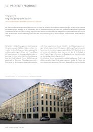
· Project »Dexia Bank«<br />
· Project »Altstadtpalais«<br />
· Example Wall/Ceiling Installation<br />
· Combination with Multifunctional<br />
Ceiling Covers <strong>and</strong> LED Lights<br />
© 2010 <strong>TTC</strong> <strong>Timmler</strong> <strong>Technology</strong> GmbH<br />
This document or any part thereof may not be<br />
reprinted, copied, or translated <strong>and</strong> figures <strong>and</strong><br />
diagrams may not be used without prior permission<br />
in writing from <strong>TTC</strong> <strong>Timmler</strong> <strong>Technology</strong> GmbH.<br />
3
Order Key for Floor Units<br />
4<br />
Order Key for <strong>TTC</strong> <strong>Chilled</strong> <strong>Beams</strong><br />
ACBLO 30 60 2 H 6 B<br />
Air discharge direction<br />
S = Vertical air discharge (passive chilled beams)<br />
B = 2-sided air discharge (in air flow direction)<br />
R = Single-sided air discharge to the right (in air flow direction)<br />
L = Single-sided air discharge to the left (in air flow direction) 4 = 4-sided air discharge<br />
Power level<br />
<strong>Active</strong> <strong>Chilled</strong> <strong>Beams</strong> <strong>Passive</strong> <strong>Chilled</strong> <strong>Beams</strong><br />
Type ACBLQ ACBLZ ACBLA ACBLE ACBLO AECAK AECBK AECBU AECEU<br />
-- -- -- -- -- 0 0 0 0<br />
-- 1 -- -- -- -- -- -- --<br />
6* -- 6* 6* 6* -- -- -- --<br />
7 -- 7 7 7 -- -- -- --<br />
-- -- 8 8 -- -- -- -- --<br />
9 -- 9 9 9 -- -- -- --<br />
12 -- 12 12 12 -- -- -- --<br />
*Power level 6 on request<br />
Power Level<br />
Water supply connection<br />
H = Horizontal<br />
V = Vertical<br />
Pipe divisions<br />
1 (2, 3, 4 on request)<br />
Unit width Wtot[mm]<br />
36 = for depth 362 mm<br />
45 = for depth 455 mm<br />
60 = for depth 605 <strong>and</strong> 592 mm<br />
Unit length Ltot[mm]<br />
<strong>Active</strong> <strong>Chilled</strong> <strong>Beams</strong> <strong>Passive</strong> <strong>Chilled</strong> <strong>Beams</strong><br />
Type ACBLQ ACBLZ ACBLA ACBLE ACBLO AECAK AECBK AECBU AECEU<br />
Unit length Ltot[mm]<br />
600 -- -- -- -- 1000 1000 1000 1000<br />
-- 1200 1200 1200 1200 1500 1500 1500 1500<br />
-- -- 1800 1800 1800 2000 2000 2000 2000<br />
-- -- 2400 2400 2400 2500 2500 2500 2500<br />
-- -- -- -- -- 3000 3000 3000 3000<br />
-- -- -- -- -- 3500 3500 3500 3500<br />
-- -- -- -- -- 4000 4000 4000 4000<br />
Models<br />
<strong>Active</strong> <strong>Chilled</strong> <strong>Beams</strong> <strong>Passive</strong> <strong>Chilled</strong> <strong>Beams</strong><br />
ACBLQ AECAK<br />
ACBLZ AECBK<br />
ACBLA AECBU<br />
ACBLE<br />
ACBLO<br />
AECEU<br />
Subject to technical changes · Issued 10/2010
Subject to technical changes · Issued 10/2010<br />
Why air conditioning?<br />
The benefit of air conditioning<br />
Our thermal well-being depends on a num-<br />
ber of factors. Our body will always try<br />
to balance its heat regulation so that all<br />
organs can work properly. In order for our<br />
organs <strong>and</strong> circulation to perform at opti-<br />
mum level our body temperature needs to<br />
remain at a constant 37 0 C. This can only<br />
be achieved if both all sources that may<br />
generate heat (such as muscle activity, the<br />
burning of calories, etc.) <strong>and</strong> all ways to<br />
get rid of surplus heat (such as chivering,<br />
thin clothes, etc.) are in balance. Studies<br />
by P. O. Fanger have shown that people will<br />
only feel comfortable if they are in a neutral<br />
thermal state (Fig. 5.2), i.e. their ideal<br />
temperature is not disturbed. However, this<br />
ideal temperature may vary slightly from<br />
person to person.<br />
Any deviation from this ideal temperature<br />
will result in a drop in performance from<br />
this person <strong>and</strong> reduce his productivity as<br />
well as his sense of well-being (Fig. 5.1).<br />
This important fact should always be taken<br />
into account when making an investment.<br />
Depending on ambient temperature, clothing<br />
<strong>and</strong> Type of activity performed we<br />
regulate our body heat through convection<br />
<strong>and</strong> radiation (sensible heat discharge)<br />
Performance drop [%]<br />
5.1<br />
Interior wall temperature [°C]<br />
5.2<br />
100<br />
90<br />
80<br />
70<br />
60<br />
50<br />
40<br />
30<br />
25<br />
21<br />
20<br />
16<br />
15<br />
-6 -5 -4 -3 -2 -1 0 +1 +2 +3 +4 +5 +6<br />
Deviation from the ideal temperature [°C]<br />
t e = 21 0 C<br />
k = 0,5 W/m2•K 190C<br />
k = 1,0 W/m2•K<br />
k = 1,5 W/m2•K<br />
10<br />
10 15 20 23 25 30<br />
Deviation from the ideal temperature [°C]<br />
Comfort zone (Source: Paperback »Heizung und Klimatechnik«,<br />
by Recknagel, Sprenger & Höhnmann)<br />
t = Perceived temperature, t = Outdoor tempera-<br />
e a<br />
ture, k = Heat transfer rate of the walls<br />
•<br />
23°C<br />
ta = -10°C<br />
or the evaporation of sweat (latent heat<br />
discharge) as illustrated in Fig. 5.3).<br />
· Type of clothing worn<br />
· Air temperature<br />
· Relative humidity<br />
· Air flow<br />
· Temperature of the surrounding surfaces<br />
· Level of a person’s physical activity, etc.<br />
Heat discharge [W]<br />
5.3<br />
160<br />
140<br />
120<br />
100<br />
80<br />
60<br />
40<br />
20<br />
0<br />
Convection<br />
Evaporation<br />
Radiation<br />
10 14 18 22 26 30 34 38<br />
Air temperature [°C]<br />
Is ventilation necessary?<br />
The German St<strong>and</strong>ard DIN 1946/Part 2/<br />
Section 3.2 makes outside air flow rates<br />
compulsory for enclosed spaces so that<br />
people who work in these rooms are supplied<br />
with pre-conditioned outside air.<br />
In addition, a central ventilation system<br />
will remove the latent cooling percentage<br />
(air humidity) <strong>and</strong> any smells from the<br />
rooms.<br />
However, the air volume flow may be reduced<br />
to the legal requirement. This would<br />
result in a substantial reduction in the size<br />
of the ventilation system needed.<br />
»A min« minimum distances between active chilled beams arranged in parallel<br />
If several active chilled beams are to be arranged<br />
in parallel the units must be spaced<br />
a minimum distance »Amin« apart.<br />
To roughly calculate the distance between<br />
the units you can use the formula<br />
Amin = 1,4 · aL <strong>and</strong> Fig. 5.4.<br />
The diagram applies to the one-sided air<br />
discharge only; for two-sided air<br />
7<br />
discharge you will need to halve<br />
the air volume flow<br />
6<br />
VL(specif) when you determine the<br />
5<br />
Amin spacing.<br />
Example:<br />
<strong>Chilled</strong> beam with two-sided<br />
air discharge,<br />
VL(specif) = 47 (m³/h·m),<br />
required air flow rate in the room<br />
vL = 0,2 m<br />
Reference distance aL [m]<br />
4<br />
3<br />
2<br />
1,2<br />
1<br />
0<br />
l/(s·m)<br />
How do chilled beams work?<br />
<strong>TTC</strong> chilled beams always directly affect<br />
the air that circulates in a room <strong>and</strong> any<br />
heat sources present. A chilled beam’s<br />
cooling capacity is always supplied to the<br />
room in the form of a natural no-draught<br />
convection. This ensures a high level of<br />
comfort as regards the protection from<br />
draughts <strong>and</strong> noises.<br />
<strong>TTC</strong> chilled beams are available in two<br />
designs:<br />
· <strong>Active</strong> chilled beams with air supply<br />
connection<br />
· <strong>Passive</strong> chilled beams<br />
<strong>Active</strong> chilled beams have a constant air<br />
flow rate because of the central ventilation<br />
system. <strong>Passive</strong> chilled beams change<br />
their air flow rate <strong>and</strong> cooling capacity<br />
dependent on the temperature difference<br />
between the room temperature <strong>and</strong> the<br />
surface temperature of the chilled beams.<br />
For this Type of chilled beam the supply<br />
air flow rate, a compulsory requirement<br />
of the German St<strong>and</strong>ard DIN 1946/Part 2/<br />
Section 3.2, must be provided using an<br />
additional ventilation system.<br />
Note!<br />
Please refer to our planning document<br />
»<strong>TTC</strong> Silent Gravity Cooling Modultherm«<br />
where you will find further information on<br />
how temperature differences cause people<br />
discomfort <strong>and</strong> how well various air conditioning<br />
systems are accepted.<br />
aL = 47 m³/(h·m) · 0,5 = 23,5 m³/(h·m)<br />
equals: aL = 1,2 m<br />
The »Amin« spacing between the chilled<br />
beams can now be calculated as follows:<br />
Amin = aL[m] · 1,4 = 1,2 m · 1,4 = 1,68 m<br />
If there are very high thermal loads the<br />
parameter »Amin« can be reduced.<br />
v L = 0,2 m/s<br />
v L = 0,25 m/s<br />
5 6 7 8 9 10 11 12 13 14 15 16<br />
m 20 25 30 35 40 45 50 55<br />
3/(h·m)<br />
23,5<br />
Specific air volume flow<br />
5.4 5
Products in Use | Examples<br />
Cooling, Heating, Ventilation<br />
Fig. 6.1 shows an example how a room<br />
can be fully air conditioned – cooled, heated<br />
<strong>and</strong> ventilated – with <strong>TTC</strong> model ACBLE<br />
chilled beams <strong>and</strong> underfloor convectors<br />
for the heating mode.<br />
Air conditioning a room using <strong>TTC</strong> <strong>Chilled</strong> <strong>Beams</strong><br />
[1] <strong>TTC</strong> chilled beam, e.g. model ACBLE<br />
[2] Cold water return<br />
[3] Flexible pipe for the pre-conditioned<br />
outside air<br />
[4] Cold water flow<br />
[5] Dew sensor to prevent the temperature<br />
in the chilled beam from falling<br />
below the dew point (to be installed<br />
in the cold water flow »inside« the<br />
chilled beam to pick up the condition<br />
in the room)<br />
[6] Cooling mode control valve<br />
[7] Sequential controller for heating or<br />
cooling mode with a neutral zone<br />
between the two modes<br />
[8] Heating flow<br />
[9] Heating return<br />
[10] Heating mode control valve<br />
(inside the floor channel)<br />
[11] Radiator, e.g. <strong>TTC</strong> underfloor<br />
trenchheater<br />
[12] Cold water return<br />
[13] Cold water flow<br />
6<br />
Heat transfer through people [W]<br />
· The illustration does not show the air<br />
h<strong>and</strong>ling unit required to pre-condition<br />
the primary air supply.<br />
· To supply the chilled beams with cold<br />
water you can either use suitable cold<br />
Activity ≈ W Level of Activity ≈ W/m³<br />
Sleeping 60 –– 35<br />
Lying down 80 –– 45<br />
Normal office work 100 I 55<br />
Typing 150 II 85<br />
Walking slowly 3 km/h 200 III 110<br />
Walking fast 6 km/h 250 IV<br />
Heavy physical work ≥170<br />
AL Supply air to ventilate the room <strong>and</strong><br />
possibly to absorb humidity from the<br />
room (minimum supply air flow rates<br />
need to be complied with in line with<br />
German St<strong>and</strong>ard DIN 1946/Part 2/<br />
Section 3.2)<br />
FL Air passage grill to remove hygienically<br />
[11]<br />
~<br />
[1] [2] [AL] [3] [4] [5] [6] [12]<br />
Z Z Z<br />
[10] [9]<br />
U<br />
[8]<br />
water generators in heat pump mode<br />
or dry cooling towers to benefit from<br />
energy saving »freecooling«.<br />
You will find more information on how<br />
to correctly control chilled beams on<br />
page 7.<br />
tainted recirculating air (escaping air)<br />
U Warm recirculating air<br />
Z Outside <strong>and</strong> recirculating air that has<br />
been cooled in the chilled beam<br />
FL<br />
U<br />
<br />
~<br />
•<br />
•<br />
•<br />
6.1<br />
[13]<br />
[7]<br />
Subject to technical changes · Issued 10/2010
Subject to technical changes · Issued 10/2010<br />
Operation <strong>and</strong> Function<br />
<strong>Chilled</strong> beams are generally controlled<br />
with individual room or zone thermostats.<br />
This aims to satisfy the individual needs of<br />
the users. Room thermostats are installed<br />
to sequentially control the cooling <strong>and</strong><br />
heating valve. This prevents any overlap<br />
between the heating <strong>and</strong> the cooling<br />
mode. The thermoelectrical actuators are<br />
applied to the room thermostat which<br />
is used to control the system based on a<br />
variance comparison.<br />
As the chilled beams are to remove<br />
sensible cooling loads only, a drop below<br />
the dew point must be avoided. It makes<br />
sense to install a dew sensor in the control<br />
circuit which will close the cooling valve if<br />
a drop below the dew point is detected.<br />
The chilled beams will discharge the cool<br />
air in a very natural way. The difference<br />
in temperature between the air in the<br />
room <strong>and</strong> on the surface of the air<br />
cooler (floating temperature difference)<br />
automatically controls the level of cool air<br />
that is discharged.<br />
A two-point valve control (OPEN-CLOSED)<br />
for the chilled beams is totally adequate<br />
<strong>and</strong> has the benefit of providing you with a<br />
considerable cost saving.<br />
Components needed<br />
A zone can be controlled (sequential control)<br />
with the following components:<br />
· 1 off valve box (valve gate), suitable for<br />
the installation of an electrical actuator<br />
· 1 off valve box (three-way valve) for<br />
the zone mixing control, suitable for the<br />
installation of an electrical actuator<br />
· 2 off 24 V actuators (currentless, normally<br />
closed)<br />
· 1 off dew sensor<br />
· 1 off room thermostat<br />
· 1 off chilled beam controller, suitable for<br />
Controls <strong>and</strong> schematic diagram for an air conditioning system using chilled beams in cooling mode<br />
[1] <strong>TTC</strong> chilled beams (active)<br />
[2] Sequential control for one zone to be<br />
air conditioned<br />
[3] Room thermostat or room sensor for<br />
cooling/heating (incl. a neutral zone)<br />
[4] Overflow valve to avoid an increase of<br />
pressure in the pipe system<br />
7.1<br />
Central unit with heat recovery (as an example)<br />
[11]<br />
[12]<br />
~<br />
[13]<br />
[5] Three-way control valve for one zone<br />
[6] Secondary pump for one cooling circuit<br />
[7] Zone control valve with thermoelectrical<br />
actuator (currentless, normally closed)<br />
[8] Dew sensor to monitor the dew point<br />
[9] Electrical stop valves (OPEN-CLOSED)<br />
[10] Water circulating pumps for operation<br />
[14] ~<br />
[10]<br />
~<br />
[9]<br />
[10]<br />
[9]<br />
~<br />
[15]<br />
heating/cooling mode <strong>and</strong> the connection<br />
of a dew sensor<br />
· 1 off circulating pump to control the<br />
flow temperature<br />
Note!<br />
Please do not hesitate to contact us with<br />
any questions you might have concerning<br />
your planning requirements.<br />
with a cooling tower<br />
[11] Dry cooling tower<br />
[12] Three-way switching valve<br />
[13] Water cooled cold water set<br />
[14] Three-way control-valve to cool the<br />
outside air<br />
[15] Plate heat exchanger<br />
[8]<br />
[7]<br />
[6]<br />
[5]<br />
[9]<br />
~<br />
~<br />
~<br />
RT<br />
<br />
Note!<br />
This diagram<br />
does not show<br />
the m<strong>and</strong>atory<br />
heaters.<br />
[1]<br />
[2]<br />
[3]<br />
[4]<br />
7
Cassette <strong>Chilled</strong> Beam ACBLQ 0660 (active)<br />
Specification | Capacity Charts<br />
8.1<br />
8<br />
Dimensions<br />
8.2 ACBLQ 0660 side view<br />
8.3<br />
8.2–8.3<br />
Air-sided pressure difference ∆pL [Pa]<br />
A<br />
D B<br />
1000<br />
700<br />
500<br />
400<br />
300<br />
200<br />
150<br />
100<br />
70<br />
50<br />
30<br />
20<br />
10<br />
C<br />
ACBLQ<br />
Note!<br />
4 air discharge directions for the air<br />
supply. Air adjustment valves which<br />
come as st<strong>and</strong>ard allow 4 different<br />
settings for the air volume flow.<br />
The power levels in charts 8.4 to 8.7<br />
apply only when the air adjustment<br />
valves are fully open (100 %).<br />
Air resistance, Sound pressure level*)<br />
Pressure drop [Pa], sound pressure level dB(A)<br />
Power level 7, 9 <strong>and</strong> 12 (100 % open)<br />
Level 7/4<br />
Level 9/4<br />
Level 12/4<br />
30 dB(A)<br />
40 dB(A)<br />
25 dB(A)<br />
30<br />
25 40 50 60 70 80 100 150 200 250<br />
8.4 Air volume flow VL [m³/h]<br />
35 dB(A)<br />
The sound pressure level [dB(A)] refers to an effective room area<br />
of 10 m² Sabine <strong>and</strong> a reverbation period of 0,5 seconds.<br />
Capacity charts, 4-sided air discharge<br />
700<br />
650<br />
600<br />
550<br />
500<br />
450<br />
400<br />
350<br />
300<br />
250<br />
200<br />
150<br />
100<br />
PL. 7<br />
Cooling capacity [W] Cooling capacity ACBLQ 0660 | Power level 7<br />
90 m3/h<br />
80 m3/h<br />
70 m3/h<br />
60 m3/h<br />
50 m3/h<br />
40 m3/h<br />
36 m3/h<br />
5 6 7 8 9 10 11 12<br />
8.5 Temperature difference ∆m [K]<br />
700<br />
650<br />
m3/h<br />
600 100<br />
550<br />
500<br />
450<br />
400<br />
350<br />
300<br />
250<br />
200<br />
PL. 9<br />
Cooling capacity [W] Cooling capacity ACBLQ 0660 | Power level 9<br />
120 m3/h<br />
80 m3/h<br />
72 m3/h<br />
5 6 7 8 9 10 11 12<br />
8.6 Temperature difference ∆m [K]<br />
600<br />
550<br />
500<br />
450<br />
400<br />
350<br />
300<br />
250<br />
200<br />
LPL 12 140 m3/h<br />
Cooling capacity [W] Cooling capacity ACBLQ 0660 | Power level 12<br />
130 m3/h<br />
120 m3/h<br />
100 m3/h<br />
90 m3/h<br />
5 6 7 8 9 10 11 12<br />
8.7 Temperature difference ∆m [K]<br />
Subject to technical changes · Issued 10/2010
Subject to technical changes · Issued 10/2010<br />
Cassette <strong>Chilled</strong> Beam ACBLQ 0660 (active)<br />
Design Features | Installation Example<br />
Design features for model ACBLQ<br />
The cassette chilled beam model ACBLQ<br />
is an active chilled beam. It’s design <strong>and</strong><br />
operation combines a ceiling air discharge<br />
with a decentralized cooling unit.<br />
This means that none of the usual additional<br />
air discharge points are required<br />
which in turn helps to optimize both the<br />
investment <strong>and</strong> the energy costs. The design<br />
allows for trouble-free installation in<br />
st<strong>and</strong>ard panelled ceilings which makes the<br />
unit suitable for a whole host of applications.<br />
The units can be installed flush in<br />
panelled ceilings.<br />
Air cooler<br />
The air cooler is made of copper pipes<br />
covered with aluminium fins. To ensure a<br />
continuous heat transfer the fins <strong>and</strong> the<br />
pipes are bonded together..<br />
· The water quality of the coolant must<br />
meet the requirements of the German<br />
St<strong>and</strong>ard VDI 2035<br />
· Maximum operating pressure 6 bar*<br />
· Maximum operating temperature 90°C*<br />
*Further installation options on request<br />
Connections<br />
The connecting pipes projects horizontally<br />
»H« from the casing. The copper connection<br />
pipes have a diameter of 15 mm.<br />
The connections are suitable for soldered<br />
joints, clamping joints <strong>and</strong> crimped connections.<br />
Casing<br />
The casing is made of coated steel plate<br />
(the colour is white, similar to RAL 9010).<br />
The cover can be removed for maintenance<br />
purposes. For dimensions see Fig. 8.2.<br />
A ø 125 mm air inlet connector is located<br />
at the top of the casing. Upon request the<br />
unit can also be supplied with this connector<br />
located at the side.<br />
An air adjustment to individually control<br />
the supply air volume flows on each air<br />
discharge side comes as st<strong>and</strong>ard.<br />
Options<br />
· ø 125 mm air inlet connector located at<br />
the side of the unit<br />
Applications<br />
Offices, open plan offices, administrative<br />
buildings, restaurants, showrooms, galleries,<br />
supermarkets, department stores, etc.<br />
Flush installation in panelled ceiling | Central recirculating air inlet<br />
[1] Panelled ceiling<br />
[2] Perforated cover<br />
to suck in recirculating air<br />
[U] Warm recirculating air<br />
[Z] Cooled supply air<br />
9.1 Installation example <strong>and</strong> function<br />
8<br />
7<br />
6<br />
5<br />
4<br />
3<br />
2<br />
1<br />
0<br />
kg/h<br />
kg/s<br />
10<br />
9<br />
Z<br />
ACBLQ 0660<br />
Water-sided pressure drop [kPa] Water-sided pressure drop* [∆pw]<br />
1 pipe division<br />
0 100 200 300 400 500<br />
0 0,05 0,10 0,15<br />
9.2 Water volume flow m˙ w [kg/h]<br />
* Note!<br />
You can calculate the water-sided pressure difference [kPa] of the panelled chilled beam,<br />
model ACBLQ, using the water volume flow (Formula 4) in Fig. 9.2.<br />
Further pressure optimization on request.<br />
Formula 1 to calculate the average<br />
temperature difference ∆m<br />
tW1 [°C] + tW2 [°C]<br />
∆m[K] = tR -<br />
2<br />
U<br />
Z<br />
[2]<br />
[1]<br />
Formula 4 to roughly estimate the water<br />
volume flow m˙ W<br />
Q · k(tot) [kW]<br />
m˙ W[kg/h] = 860 ·<br />
tW2 - tW1 [K]<br />
9
<strong>Chilled</strong> Beam ACBLZ (active)<br />
Specification | Capacity Charts<br />
10.1<br />
Dimensions<br />
10.2<br />
10<br />
AL<br />
56<br />
146 186 203<br />
297<br />
≈50 9x60<br />
594<br />
1260<br />
Technical data | Weights<br />
10.3<br />
10<br />
9<br />
8<br />
7<br />
6<br />
5<br />
4<br />
3<br />
2<br />
1<br />
∅15 ∅100<br />
alternative supply air connection<br />
Type L(tot)<br />
[mm]<br />
ACBLZ<br />
1 Rohrteilung<br />
Water-sided pressure drop [kPa/m] Water-sided pressure difference [∆pw]<br />
L(finned)<br />
[mm]<br />
∅15<br />
130<br />
146<br />
200<br />
0<br />
kg/h 0 50 100 150 200 250 300 350<br />
kg/s 0 0,05 0,10<br />
10.4 Water volume flow m˙ W [kg/h]<br />
Water-sided<br />
1 pipe division<br />
Weight<br />
[kg]<br />
ACBLZ 1260 1193 1000 24<br />
Cooling capacity [W]<br />
Capacity charts 2-sided air discharge<br />
Specif. cooling capacity ACBLZ 1260.1.2<br />
Air adjustment valve in position 0<br />
700<br />
600<br />
500<br />
400<br />
300<br />
200<br />
ACBLZ / 0<br />
60 m3/h<br />
40 m3/h<br />
20 m3/h<br />
100<br />
50<br />
5 6 7 8 9 10 11 12<br />
10.5<br />
Temperature difference ∆m [K]<br />
Air adjustment valve in position 5<br />
Cooling capacity [W]<br />
600<br />
500<br />
400<br />
300<br />
200<br />
ACBLZ / 5<br />
60 m3/h<br />
40 m3/h<br />
20 m3/h<br />
100<br />
50<br />
5 6 7 8 9 10 11 12<br />
10.6<br />
Temperature difference ∆m [K]<br />
Air adjustment valve in position 10<br />
Cooling capacity [W]<br />
10.7<br />
600<br />
500<br />
400<br />
300<br />
200<br />
100<br />
50<br />
1000<br />
500<br />
300<br />
200<br />
100<br />
50<br />
40<br />
m3/h<br />
ACBLZ / 10<br />
60 m3/h<br />
40 m3/h<br />
20 m3/h<br />
5 6 7 8 9 10 11 12<br />
Temperature difference ∆m [K]<br />
Position 0<br />
Position 5<br />
Position 10<br />
30 dB(A)<br />
40 dB(A)<br />
25 dB(A)<br />
Air-sided pressure difference ∆pL [Pa] Air resistance | Sound pressure level*)<br />
10.8<br />
35 dB(A)<br />
20 25 30 40 50 60 80 100 130<br />
Air volume flow vL [m³/h]<br />
Subject to technical changes · Issued 10/2010
Subject to technical changes · Issued 10/2010<br />
<strong>Chilled</strong> <strong>Beams</strong> ACBLZ (active)<br />
Design Features | Installation Example<br />
Design features for model ACBLZ<br />
The panelled chilled beam model ACBLZ<br />
is an active air conditioning unit. As it<br />
requires a supply air flow to operate it<br />
automatically meets the requirements<br />
regarding the ventilation of a room. An air<br />
adjustment valve to control the air flow<br />
volume comes as st<strong>and</strong>ard. Installation<br />
of the unit is in panelled ceilings. An<br />
additional air passage grill is not required.<br />
The structural design of the units will be<br />
explained in the following.<br />
Air cooler<br />
The air cooler is made of copper pipes<br />
covered with aluminium fins. To ensure a<br />
continuous heat transfer the fins <strong>and</strong> the<br />
pipes are bonded together.<br />
· The water quality of the coolant must<br />
meet the requirements of the German<br />
St<strong>and</strong>ard VDI 2035<br />
· Maximum operating pressure 6 bar<br />
· Maximum operating temperature 90°C<br />
Connections<br />
The chilled beams will be supplied with<br />
»H« (horizontal) connection pipes only. The<br />
connection pipes average diameter is<br />
· ø 15 mm with one pipe division<br />
· ø 22 mm with two or more pipe divisions.<br />
The supply air connection (ø 100 mm) is<br />
located at the end or alternatively at the<br />
top of the unit.<br />
Casing<br />
The casing is made of coated steel plate<br />
(the colour is white, similar to RAL 9010).<br />
The perforated recirculating air inlet cover<br />
can be removed for maintenance purposes.<br />
For dimensions see Fig. 10.2.<br />
Two mounting rails run along the top of<br />
the whole unit. The mounting brackets<br />
which are included in the delivery are attached<br />
to these rails.<br />
Options<br />
· Integrated light fixture<br />
Installation notes<br />
If the chilled beams are to be arranged in<br />
parallel the installation requirements illustrated<br />
in Fig. 11.2 must be complied with<br />
to ensure a trouble-free operation.<br />
Applications<br />
Offices, open plan offices, administrative<br />
buildings, restaurants, showrooms, sound<br />
<strong>and</strong> TV studios, supermarkets, department<br />
stores, etc.<br />
Flush installation in panelled ceiling<br />
Z<br />
U<br />
[U] Warm recirculating air entering the ch. b.<br />
[Z] Cooled recirculating <strong>and</strong> supply air leaving the ch. b.<br />
[AL] Centrally conditioned outside air<br />
11.1 Installation example <strong>and</strong> function<br />
»Amin« minimum distances between chilled beams arranged in parallel<br />
2-sided air discharge<br />
11.2<br />
U<br />
Model ACBLZ chilled beams are installed in panelled ceilings only. An additional air passage<br />
grill is not required.<br />
If a number of chilled beams are needed to meet the cooling requirements of the room<br />
the minimum installation distances given in Fig. 11.2 must be observed.<br />
Supply air channel<br />
Amin.≥ 0,7 · aL B<br />
Amin.≥ 1,4 · aL *) B Amin.≥ 0,7 · aL<br />
*)aL = Reference spacing (see page 5)<br />
[B] Width of the chilled beam, see Fig. 10.2<br />
[Amin] Minimum distance between two chilled beams or a chilled beam <strong>and</strong> a wall, in line<br />
with the air volume flow, see Fig. 5.4<br />
Note!<br />
You can calculate the water-sided pressure difference [kPa] of the panelled chilled beam,<br />
model ACBLZ, using the water volume flow (Formula 4) in Fig. 10.4.<br />
Formula 1 to calculate the average<br />
temperature difference ∆m<br />
tW1 [°C] + tW2 [°C]<br />
∆m[K] = tR -<br />
2<br />
Z<br />
AL<br />
Q · Formula 4 to roughly estimate the water<br />
volume flow m˙ W<br />
K(tot) [kW]<br />
m˙ W[kg/h] = 860 ·<br />
tW2 - tW1 [K]<br />
11
<strong>Chilled</strong> Beam ACBLA (active)<br />
Specification | Capacity Charts<br />
12.1<br />
Dimensions<br />
12<br />
Water-sided<br />
1 pipe division<br />
AL<br />
12.2<br />
86<br />
50<br />
41<br />
∅15<br />
30<br />
182<br />
Technical data | Weights<br />
12.3<br />
8<br />
7<br />
6<br />
186<br />
L(ges.)<br />
Type L(tot)<br />
[mm]<br />
ACBLA 36<br />
∅15 ∅125<br />
364<br />
159<br />
171<br />
9x60<br />
170<br />
5<br />
4<br />
3<br />
2<br />
1<br />
0<br />
kg/h 0 50 100 150 200 250 300 350 400 450<br />
kg/s<br />
0 0,05 0,10 0,13<br />
Water-sided pressure difference [kPa/m] Water-sided pressure difference [∆pw]<br />
12.4 Water volume flow m˙ w [kg/h]<br />
L(finned)<br />
[mm]<br />
Weight<br />
[kg]<br />
ACBLE 1236 1193 1000 24<br />
ACBLE 1836 1793 1600 36<br />
ACBLE 2436 2393 2200 48<br />
ACBLE 3036 2993 2800 60<br />
Capacity Charts 2-sided air discharge<br />
Specif. cooling capacity [q˙ K(spez)] ACBLA __36<br />
12.5<br />
12.6<br />
12.7<br />
800<br />
700<br />
600<br />
500<br />
400<br />
300<br />
Cooling capacity [W/m] Power level 7<br />
200<br />
100<br />
50<br />
700<br />
600<br />
500<br />
400<br />
300<br />
200<br />
Cooling capacity [W/m] Power level 8<br />
100<br />
50<br />
600<br />
500<br />
400<br />
300<br />
200<br />
Cooling capacity [W/m] Power level 9<br />
100<br />
50<br />
500<br />
400<br />
300<br />
200<br />
PL. / 8<br />
60 m3/h·m<br />
40 m3/h·m<br />
20 m3/h·m<br />
5 6 7 8 9 10 11 12<br />
Temperature difference ∆m [K]<br />
PL. / 9<br />
60 m3/h·m<br />
40 m3/h·m<br />
20 m3/h·m<br />
5 6 7 8 9 10 11 12<br />
Temperature difference ∆m [K]<br />
PL. / 12<br />
60 m3/h·m<br />
40 m3/h·m<br />
20 m3/h·m<br />
100<br />
50<br />
5 6 7 8 9 10 11 12<br />
12.8 Temperature difference ∆m [K]<br />
Cooling capacity [W/m] Power level 12<br />
PL. / 7<br />
60 m3/h·m<br />
40 m3/h·m<br />
20 m3/h·m<br />
5 6 7 8 9 10 11 12<br />
Temperature difference ∆m [K]<br />
Subject to technical changes · Issued 10/2010
Subject to technical changes · Issued 10/2010<br />
<strong>Chilled</strong> Beam ACBLA (active)<br />
Design Features | Installation Example<br />
Design features for model ACBLA<br />
Model ACBLA panelled chilled beams<br />
are active air conditioning units. As they<br />
require a supply air flow to operate they<br />
automatically meet the requirements<br />
regarding the ventilation of a room. Installation<br />
of the units is underneath ceilings<br />
only. An additional air passage grill is not<br />
required. The structural design of the units<br />
will be explained in the following.<br />
Air cooler<br />
The air cooler is made of copper pipes<br />
covered with aluminium fins. To ensure a<br />
continuous heat transfer the fins <strong>and</strong> the<br />
pipes are bonded together.<br />
· The water quality of the coolant must<br />
meet the requirements of the German<br />
St<strong>and</strong>ard VDI 2035<br />
· Maximum operating pressure 6 bar<br />
· Maximum operating temperature 90°C<br />
Connections<br />
The chilled beams will be supplied with<br />
»H« (horizontal) connection pipes only. The<br />
connection pipes average diameter is<br />
· ø 15 mm with one pipe division<br />
· ø 22 mm with two or more pipe divisions.<br />
The supply air connection (ø 100 mm) is<br />
located at the end or alternatively at the<br />
top of the unit.<br />
Casing<br />
The casing is made of coated steel plate<br />
(the colour is white, similar to RAL 9010).<br />
The perforated recirculating air inlet cover<br />
can be removed for maintenance purposes.<br />
For dimensions see Fig. 11.2.<br />
Two mounting rails run along the top of<br />
the whole unit. The mounting brackets<br />
which are included in the delivery are attached<br />
to these rails.<br />
Options<br />
· Available unit lengths: 12–36 dm in 6 dm<br />
increments<br />
Installation notes<br />
Model ACBLA chilled beams are always<br />
installed directly underneath the ceiling.<br />
If the chilled beams are to be arranged in<br />
parallel the installation requirements illustrated<br />
in Fig. 13.2 must be complied with<br />
to ensure a trouble-free operation.<br />
Applications<br />
Offices, open plan offices, administrative<br />
buildings, restaurants, showrooms, sound<br />
<strong>and</strong> TV studios, supermarkets, department<br />
stores, etc.<br />
Installation underneath a ceiling<br />
13.1 Installation example <strong>and</strong> function<br />
Z<br />
[U] Warm recirculating air entering the ch. b.<br />
[Z] Cooled recirculating <strong>and</strong> supply air leaving the ch. b.<br />
[AL] Centrally conditioned outside air<br />
Z<br />
U<br />
AL<br />
Model ACBLA chilled beams are always installed underneath a ceiling. An additional air<br />
passage grill is not required.<br />
If a number of chilled beams are needed to meet the cooling requirements of the room<br />
the minimum installation distances given in Fig. 13.2 must be observed.<br />
»Amin« Minimum distances between chilled beams arranged in parallel<br />
2-sided air discharge<br />
13.2<br />
Amin 0,7 · aL B<br />
Amin 1,4 · aL *) B Amin 0,7 · aL<br />
*)aL = Reference spacing (see page 5)<br />
[B] Width of the chilled beam, see Fig. 12.2<br />
[Amin] Minimum distance between two chilled beams or a chilled beam <strong>and</strong> a wall, in line<br />
with the air volume flow, see Fig. 5.4<br />
Note!<br />
You can calculate the water-sided pressure difference [kPa] of the panelled chilled<br />
beam, model ACBLZ, using the water volume flow (Formula 4) in Fig. 12.4; please use<br />
Fig. 17.1–17.4 to calculate the sound pressure level.<br />
Formula 1 to calculate the average<br />
temperature difference ∆m<br />
tW1 [°C] + tW2 [°C]<br />
∆m[K] = tR -<br />
2<br />
Z<br />
U<br />
U<br />
Z<br />
Formula 4 to roughly estimate the water<br />
volume flow m˙ W<br />
q˙ (spezif) [kW/m] · L(finned)[m]<br />
m˙ W[kg/h] = 860 ·<br />
tW2 - tW1 [K]<br />
Z<br />
Z<br />
13
<strong>Chilled</strong> Beam ACBLE (active)<br />
Specification | Capacity Charts<br />
14.1<br />
Dimensions<br />
14.2<br />
14<br />
135<br />
332,9 7,6<br />
Technical data | Weights<br />
14.3<br />
8<br />
7<br />
6<br />
350<br />
350<br />
439,14<br />
592<br />
1054,9<br />
1192<br />
Type L(tot)<br />
[mm]<br />
ACBLE 60<br />
1 pipe division<br />
5<br />
4<br />
3<br />
2<br />
1<br />
0<br />
kg/h 0 50 100 150 200 250 300 350 400 450<br />
kg/s<br />
0 0,05 0,10 0,13<br />
Water-sided pressure difference [kPa/m] Water-sided pressure difference [∆pw]<br />
14.4 Water volume flow m˙ w [kg/h]<br />
L(finned)<br />
[mm]<br />
165<br />
ø98<br />
Weight<br />
[kg]<br />
ACBLE 1260 1193 1000 40<br />
ACBLE 1860 1793 1600 60<br />
ACBLE 2460 2393 2200 80<br />
ACBLE 3060 2993 2800 100<br />
Cooling capacity [W/m] Power level 7<br />
Capacity Charts 2-sided air discharge<br />
Specif. cooling capacity [q˙ k(spez)] ACBLE __60<br />
800<br />
700<br />
600<br />
500<br />
400<br />
300<br />
200<br />
100<br />
50<br />
5 6 7 8 9 10 11 12<br />
14.5 Temperature difference ∆m [K]<br />
700<br />
600<br />
500<br />
400<br />
300<br />
200<br />
Cooling capacity [W/m] Power level 8<br />
PL. / 8<br />
60 m3/h·m<br />
40 m3/h·m<br />
20 m3/h·m<br />
100<br />
50<br />
5 6 7 8 9 10 11 12<br />
14.6 Temperature difference ∆m [K]<br />
600<br />
500<br />
400<br />
300<br />
200<br />
Cooling capacity [W/m] Power level 9<br />
PL. / 9<br />
60 m3/h·m<br />
40 m3/h·m<br />
20 m3/h·m<br />
100<br />
50<br />
5 6 7 8 9 10 11 12<br />
14.7 Temperature difference ∆m [K]<br />
500<br />
400<br />
300<br />
200<br />
PL. / 12<br />
60 m3/h·m<br />
40 m3/h·m<br />
20 m3/h·m<br />
100<br />
50<br />
5 6 7 8 9 10 11 12<br />
14.8 Temperature difference ∆m [K]<br />
Cooling capacity [W/m] Power level 12<br />
PL. / 7<br />
60 m3/h·m<br />
40 m3/h·m<br />
20 m3/h·m<br />
Subject to technical changes · Issued 10/2010
Subject to technical changes · Issued 10/2010<br />
<strong>Chilled</strong> Beam ACBLE (active)<br />
Design Features | Installation Example<br />
Design features for model ACBLE<br />
Model ACBLE panelled chilled beams are<br />
active air conditioning units. As they<br />
require a supply air flow to operate they<br />
automatically meet the requirements regarding<br />
the ventilation of a room. Installation<br />
of the units is in panelled ceilings. An<br />
additional air passage grill is not required.<br />
The structural design of the units will be<br />
explained in the following.<br />
Air cooler<br />
The air cooler is made of copper pipes<br />
covered with aluminium fins. To ensure a<br />
continuous heat transfer the fins <strong>and</strong> the<br />
pipes are bonded together.<br />
· The water quality of the coolant must<br />
meet the requirements of the German<br />
St<strong>and</strong>ard VDI 2035<br />
· Maximum operating pressure 6 bar<br />
· Maximum operating temperature 90°C<br />
Connections<br />
The chilled beams can be ordered with »H«<br />
(horizontal) or »V« (vertical) connection<br />
pipes only. The connection pipes average<br />
diameter is<br />
· ø 15 mm with one pipe division<br />
· ø 22 mm with two or more pipe divisions.<br />
The supply air connection (ø 100 mm) is<br />
located at the end or alternatively at the<br />
top of the unit.<br />
Casing<br />
The casing is made of coated steel plate<br />
(the colour is white, similar to RAL 9010).<br />
The perforated recirculating air inlet cover<br />
can be removed for maintenance purposes.<br />
For dimensions see Fig. 14.2.<br />
Two mounting rails run along the top of<br />
the whole unit. The mounting brackets<br />
which are included in the delivery are attached<br />
to these rails.<br />
Options<br />
· Available unit lengths: 12–36 dm in 6 dm<br />
increments<br />
Installation notes<br />
If the chilled beams are to be arranged in<br />
parallel the installation requirements illustrated<br />
in Fig. 15.2 must be complied with<br />
to ensure a trouble-free operation.<br />
Applications<br />
Offices, open plan offices, administrative<br />
buildings, restaurants, showrooms, sound<br />
<strong>and</strong> TV studios, supermarkets, department<br />
stores, etc.<br />
Installation in panelled ceiling<br />
U<br />
[U] Warm recirculating air entering the ch. b.<br />
[Z] Cooled recirculating <strong>and</strong> supply air leaving the ch. b.<br />
[AL] Centrally conditioned outside air<br />
15.1 Installation example <strong>and</strong> function<br />
Z<br />
AL<br />
U<br />
Model ACBLE chilled beams are always installed flush in panelled ceilings. An additional<br />
air passage grill is not required.<br />
If a number of chilled beams are needed to meet the cooling requirements of the room<br />
the minimum installation distances given in Fig. 15.2 must be observed.<br />
Note!<br />
Other installation options on request.<br />
Z<br />
»Amin« Minimum distance between two chilled beams arranged in parallel<br />
2-sided air discharge<br />
15.2<br />
B B<br />
Amin.≥ 0,7 · aL Amin.≥ 1,4 · aL *) Amin.≥ 0,7 · aL<br />
*)aL = Reference spacing (see page 5)<br />
[B] Width of the chilled beam, see Fig. 14.2<br />
[Amin] Minimum distance between two chilled beams or a chilled beam <strong>and</strong> a wall, in line<br />
with the air volume flow, see Fig. 5.4<br />
Note!<br />
You can calculate the water-sided pressure difference [kPa] of the panelled chilled<br />
beam, model ACBLE, using the water volume flow (Formula 4) in Fig. 14.4; please use<br />
Fig. 16.4–16.7 <strong>and</strong> 17.1–17.4 to calculate the sound pressure level.<br />
Formula 4 to roughly estimate the water<br />
volume flow m˙ w<br />
q˙ k(spezif) [kW/m] · L(finned)[m]<br />
m˙ W[kg/h] = 860 ·<br />
(tW2 - tW1) [K]<br />
Supply air channel<br />
Z<br />
15
<strong>Chilled</strong> Beam ACBLA/ACBLE (active)<br />
Specification | Capacity Charts for 1-sided Air Discharge<br />
Cooling capacity [W/m]<br />
Specif. cooling capacity [q · K(spezif)] | 1-sided air discharge<br />
Power level 8<br />
16.1<br />
16.2<br />
16<br />
700<br />
600<br />
500<br />
400<br />
300<br />
200<br />
100<br />
50<br />
600<br />
500<br />
400<br />
300<br />
200<br />
Cooling capacity [W/m] Power level 9<br />
16.3<br />
100<br />
50<br />
500<br />
400<br />
300<br />
200<br />
100<br />
50<br />
Cooling capacity [W/m] Power level 12<br />
PL. / 8<br />
5 6 7 8 9 10 11 12<br />
PL. / 9<br />
Temperature difference ∆m [K]<br />
Temperature difference ∆m [K]<br />
60 m3/h·m<br />
40 m3/h·m<br />
20 m3/h·m<br />
60 m3/h·m<br />
40 m3/h·m<br />
20 m3/h·m<br />
5 6 7 8 9 10 11 12<br />
PL. / 12<br />
60 m3/h·m<br />
40 m3/h·m<br />
20 m3/h·m<br />
5 6 7 8 9 10 11 12<br />
Temperature difference ∆m [K]<br />
Note!<br />
*) The sound pressure level [dB(A)] refers to an effective room<br />
area of 10 m² Sabine <strong>and</strong> a reverbation period of 0,5 seconds.<br />
Other power levels on request.<br />
Air resistance | Sound pressure level* | 1-sided air discharge<br />
ACBLA 1236<br />
ACBLE 1260<br />
16.4<br />
ACBLA 1836<br />
ACBLE 1860<br />
16.5<br />
ACBLA 2436<br />
ACBLE 2460<br />
16.6<br />
ACBLA 3036<br />
ACBLE 3060<br />
16.7<br />
Air pressure drop ∆pL [Pa]<br />
Air pressure drop ∆pL [Pa]<br />
Air resistance ∆pL [Pa]<br />
Air pressure drop ∆pL [Pa]<br />
1000<br />
500<br />
300<br />
200<br />
150<br />
100<br />
50<br />
ACBLA/E 12 dm<br />
Level 8<br />
Level 9<br />
Level 12<br />
25 dB(A)<br />
40 dB(A)<br />
35 dB(A)<br />
30 dB(A)<br />
30<br />
20<br />
m3/h 20 30 40 60 80 100<br />
Air volume flow V<br />
200<br />
· L<br />
1000<br />
500<br />
300<br />
200<br />
150<br />
100<br />
50<br />
ACBLA/E 18 dm<br />
Level 8<br />
Level 9<br />
25 dB(A)<br />
Air volume flow V · 30<br />
20<br />
m3/h 20 30 40 60 80 100<br />
L<br />
200<br />
700<br />
500<br />
300<br />
200<br />
150<br />
100<br />
50<br />
Level 12<br />
ACBLA/E 24 dm<br />
30 dB(A)<br />
35 dB(A)<br />
40 dB(A)<br />
30<br />
20<br />
15<br />
m3/h 30 40 60 80 100<br />
Air volume flow V<br />
200<br />
· L<br />
700<br />
500<br />
300<br />
200<br />
150<br />
100<br />
50<br />
Level 8<br />
Level 9<br />
Level 8-1<br />
25 dB(A)<br />
Level 9-1<br />
ACBLA/E 30 dm<br />
40 dB(A)<br />
35 dB(A)<br />
30 dB(A)<br />
Level 12-1<br />
30<br />
20<br />
15<br />
m3/h 25 30 40 60 80 100 200<br />
Air volume flow V · L<br />
Level 12<br />
Subject to technical changes · Issued 10/2010
Subject to technical changes · Issued 10/2010<br />
<strong>Chilled</strong> Beam ACBLA/ACBLE (active)<br />
Air Resistance <strong>and</strong> Sound Pressure Level for 2-sided Air Discharge<br />
Air resistance | Sound pressure level* | 2-sided air discharge<br />
ACBLA 1236<br />
ACBLE 1260<br />
17.1<br />
ACBLA 1836<br />
ACBLE 1860<br />
17.2<br />
ACBLA 2436<br />
ACBLE 2460<br />
17.3<br />
ACBLA 3036<br />
ACBLE 3060<br />
17.4<br />
Air pressure drop ∆pL [Pa]<br />
Air pressure drop ∆pL [Pa]<br />
AIr pressure drop ∆pL [Pa]<br />
Air pressure drop ∆pL [Pa]<br />
1000<br />
500<br />
300<br />
200<br />
150<br />
100<br />
50<br />
ACBLA/E 12 dm<br />
Level 7<br />
Level 8<br />
40 dB[A]<br />
35 dB[A]<br />
30 dB[A]<br />
25 dB[A]<br />
30<br />
20<br />
15<br />
m3/h 20 30 40 60 80 100<br />
Air volume flow V<br />
200<br />
· L<br />
1000<br />
500<br />
300<br />
200<br />
150<br />
100<br />
50<br />
Level 9<br />
Level 7<br />
Level 12<br />
ACBLA/E 18 dm<br />
40 dB[A]<br />
35 dB[A]<br />
30 dB[A]<br />
25 dB[A]<br />
Level 8<br />
Air volume flow V · 30<br />
20<br />
15<br />
m3/h 20 30 40 60 80 100<br />
L<br />
200<br />
1000<br />
500<br />
200<br />
100<br />
50<br />
30<br />
20<br />
10<br />
ACBLA/E 24 dm<br />
Level 7<br />
Level 8<br />
Level 9<br />
Level 9<br />
Level 12<br />
40 dB[A]<br />
35 dB[A]<br />
Level 12<br />
30 dB[A]<br />
25 dB[A]<br />
5<br />
m3/h 20 30 40 60 80 100<br />
Air volume flow V<br />
200<br />
· L<br />
1000<br />
500<br />
200<br />
100<br />
50<br />
30<br />
20<br />
10<br />
5<br />
ACBLA/E 30 dm<br />
25 dB[A]<br />
Level 7<br />
Level 8<br />
Level 9<br />
40 dB[A]<br />
35 dB[A]<br />
Level 12<br />
30 dB[A]<br />
m3/h 20 30 40 60 80 100 200<br />
Air volume flow V · L<br />
Formulas for calculation<br />
Formula 1<br />
Calculating the average temperature difference ∆m<br />
tW1 [°C] + tW2 [°C]<br />
∆m[K] = tR -<br />
2<br />
Formula 3<br />
Calculating the total cooling capacity Q˙ Ktot (1 unit)<br />
Q · K(tot)[kW] = q ˙K(specif)[W/m] · L(finned)[m]<br />
Formula 4<br />
Estimating roughly the water volume flow m˙ w<br />
q˙ (spezif) [kW/m] · L(finned)[m]<br />
m˙ W[kg/h] = 860 ·<br />
tW2 - tW1 [K]<br />
Formula 5<br />
Calculating the total water-sided pressure drop (1 unit)<br />
∆pW(tot)[kPa] = ∆qW(specif)[W/m] · L(finned)[m]<br />
Note!<br />
*) The sound pressure level [dB(A)] refers to an effective room<br />
area of 10 m² Sabine <strong>and</strong> a reverbation period of 0,5 seconds.<br />
Other power levels on request.<br />
17
<strong>Chilled</strong> Beam ACBLO (active)<br />
Specification | Capacity Charts<br />
18.1<br />
Dimensions<br />
18.2<br />
18<br />
ø15<br />
ø125<br />
405<br />
202<br />
39<br />
39<br />
296,5<br />
Technical data | Weights<br />
18.3<br />
Type<br />
L(tot)<br />
[mm]<br />
602<br />
525<br />
L(ges.)<br />
L(berippt)<br />
L(finned)<br />
[mm]<br />
60 x 9<br />
Weight<br />
[kg]<br />
20<br />
235<br />
min. distance<br />
to the ceiling<br />
[mm]<br />
ACBLO 1260 1193 1000 40 100<br />
ACBLO 1860 1793 1600 60 100<br />
ACBLO 2460 2393 2200 80 100<br />
ACBLO 3060 2993 2800 100 100<br />
Cooling capacity [W/m] Power level 7<br />
Capacity Charts 2-sided air discharge<br />
1200<br />
1100<br />
1000<br />
900<br />
800<br />
700<br />
600<br />
500<br />
400<br />
300<br />
200<br />
PL. / 6<br />
5 6 7 8 9 10 11 12<br />
18.4 Temperature difference ∆m [K]<br />
1200<br />
1100 PL. / 9<br />
1000<br />
900<br />
800<br />
700<br />
600<br />
500<br />
400<br />
300<br />
200<br />
•<br />
5 6 7 8 9 10 11 12<br />
18.5 Temperature difference ∆m [K]<br />
Cooling capacity [W/m] Power level 9<br />
1400<br />
1300<br />
1200<br />
1100<br />
1000<br />
900<br />
800<br />
700<br />
600<br />
550<br />
500<br />
400<br />
Cooling capacity [W/m] Power level 12<br />
PL. / 12<br />
66 m3/(h·m)<br />
65 m3/(h·m)<br />
108 m3/(h·m)<br />
50 m3/(h·m)<br />
36 m3/(h·m)<br />
86 m3/(h·m)<br />
65 m3/(h·m)<br />
5 6 7 8 9 10 11 12<br />
18.6 Temperature difference ∆m [K]<br />
40 m3/(h·m)<br />
36 m3/(h·m)<br />
29 m3/(h·m)<br />
22 m3/(h·m)<br />
Subject to technical changes · Issued 10/2010
Subject to technical changes · Issued 10/2010<br />
<strong>Chilled</strong> Beam ACBLO (active)<br />
Design Features | Installation Example<br />
Design features for model ACBLO<br />
Model ACBLO chilled beams are active air<br />
conditioning units. As they require a supply<br />
air flow to operate they automatically meet<br />
the requirements regarding the ventilation<br />
of a room. Installation is flush to a panelled<br />
ceiling. The structural design of the units<br />
will be explained in the following.<br />
Air cooler<br />
The air cooler is made of copper pipes<br />
covered with aluminium fins. To ensure a<br />
continuous heat transfer the fins <strong>and</strong> the<br />
pipes are bonded together.<br />
· The water quality of the coolant must<br />
meet the requirements of the German<br />
St<strong>and</strong>ard VDI 2035<br />
· Maximum operating pressure 6 bar*<br />
· Maximum operating temperature 90°C*<br />
*Other installation options on request.<br />
Connections<br />
The chilled beams can be ordered with »H«<br />
(horizontal) or »V« (vertical) connection<br />
pipes only. The connection pipes average<br />
diameter is<br />
· ø 15 mm with one pipe division<br />
· ø 22 mm with two or more pipe divisions.<br />
The supply air connection (ø 100 mm) is located<br />
at the end of the unit. (see page 18).<br />
Casing<br />
The casing is made of coated steel plate<br />
(the colour is white, similar to RAL 9010).<br />
The recirculating air inlet cover can be<br />
removed for maintenance purposes. For<br />
dimensions see Fig. 18.2.<br />
Two mounting rails run along the top of<br />
the whole unit. The mounting brackets<br />
which are included in the delivery are attached<br />
to these rails.<br />
Options<br />
· Available unit lengths: 12–36 dm in<br />
6 dm increments<br />
· 1- <strong>and</strong> 2-sided air discharge<br />
Installation notes<br />
The installation requirements for chilled<br />
beams illustrated in Fig. 18.3 in respect<br />
of the distances to the ceiling must be<br />
complied with as the stated cooling rates<br />
will not be achieved otherwise.<br />
Applications<br />
Offices, open plan offices, administrative<br />
buildings, restaurants, showrooms, sound<br />
<strong>and</strong> TV studios, supermarkets, department<br />
stores, etc.<br />
Installation in a panelled ceiling<br />
Sb<br />
U<br />
19.1 Installation example <strong>and</strong> function<br />
Z<br />
AL<br />
SL<br />
[AL] Centrally conditioned outside air<br />
[U] Warm recirculating air entering the ch. b.<br />
[Z] Cooled recirculating <strong>and</strong> supply air leaving the ch. b.<br />
[SL] Recirculating air induced by the supply air flow<br />
Model ACBLO chilled beams are always installed flush in panelled ceilings.<br />
If a number of chilled beams are needed to meet the cooling requirements of the room<br />
the minimum installation distances given in Fig. 19.2 must be observed.<br />
The edge gaps »Sb« must be at least 70 % of the free area of the chilled beam’s face view.<br />
Note!<br />
Other installation options available on request.<br />
»Amin« Minimum distances between chilled beams arranged in parallel<br />
2-sided air discharge<br />
19.2<br />
Sb Sb<br />
Dmin<br />
Amin.≥ 0,7 · aL B Amin.≥ 1,4 · aL *) B Amin.≥ 0,7 · aL<br />
*)aL = Reference spacing (see page 5)<br />
[B] Width of the chilled beam, see Fig. 18.2<br />
[Amin] Minimum distance between two chilled beams or between a chilled beam <strong>and</strong> a<br />
wall, in line with the air volume flow, see Fig. 5.4<br />
[Dmin] Minimum distance between the top edge of the chilled beam <strong>and</strong> the prefabricated<br />
or the room’s ceiling, see Fig. 18.3<br />
Z<br />
Z<br />
U<br />
19
<strong>Chilled</strong> Beam AECAK (passive)<br />
Specification | Capacity Charts<br />
20.1<br />
Dimensions<br />
20.2<br />
20<br />
255<br />
9x60<br />
375<br />
453<br />
525<br />
405<br />
9x60<br />
603<br />
Technical data | Weights<br />
20.3<br />
L(tot)<br />
[mm]<br />
L(finned)<br />
[mm]<br />
<strong>Chilled</strong><br />
beam<br />
witdh B<br />
[mm]<br />
40<br />
39<br />
142<br />
Distance to<br />
the ceiling<br />
Dmin<br />
[mm]<br />
142<br />
39<br />
Mounting brackets<br />
Up to 2,4 m 2 off<br />
from 2,5 m 3 off<br />
Connections<br />
1 pipe division<br />
ø 15; 150 mm long<br />
Water<br />
content<br />
[l]<br />
Weight<br />
[≈kg]<br />
1000 800 450 80 0,80 8<br />
1500 1300 450 80 1,20 12<br />
2000 1800 450 80 1,60 16<br />
2500 2300 450 80 2,00 20<br />
3000 2800 450 80 2,40 24<br />
3500 3300 450 80 2,80 28<br />
4000 3800 450 80 3,20 32<br />
1000 800 600 120 1,10 10<br />
1500 1300 600 120 1,65 15<br />
2000 1800 600 120 2,20 20<br />
2500 2300 600 120 2,75 25<br />
3000 2800 600 120 3,30 30<br />
3500 3300 600 120 3,85 35<br />
4000 3800 600 120 4,40 40<br />
550<br />
500<br />
450<br />
400<br />
AECAK<br />
Unit width 60<br />
350<br />
300<br />
250<br />
200<br />
150<br />
100<br />
50<br />
0<br />
0 1 2 3 4 5 6 7 8 9 10 11 12<br />
20.4 Temperature difference ∆m [K]<br />
Specif. cooling capacity [W/m] Specific cooling capacity [q ˙ K(spez)]<br />
20.5<br />
8<br />
7<br />
6<br />
5<br />
4<br />
3<br />
2<br />
1<br />
0<br />
kg/h<br />
kg/s<br />
AECBK 45<br />
AECBK 60<br />
Specif. pressure drop [kPa/m] Specific pressure drop [∆pw]<br />
Unit width 45<br />
0 100 200 300 400 500 600 700 800 900<br />
0 0,05 0,10 0,15 0,20 0,25<br />
Formulas for calculation<br />
Water volume flow m˙ w [kg/h]<br />
Formula 1<br />
Calculating the average temperature difference ∆m<br />
tW1 [°C] + tW2 [°C]<br />
∆m[K] = tR -<br />
2<br />
Formula 3<br />
Calculating the total cooling capacity Q˙ Ktot (1 unit)<br />
Q · K(tot)[kW] = q ˙K(specif)[W/m] · L(finned)[m]<br />
Formula 4<br />
Estimating roughly the water volume flow m˙ w<br />
q˙ (spezif) [kW/m] · L(finned)[m]<br />
m˙ W[kg/h] = 860 ·<br />
tW2 - tW1 [K]<br />
Formula 5<br />
Calculating the total water-sided pressure drop (1 unit)<br />
∆pW(tot)[kPa] = ∆qW(specif)[W/m] · L(finned)[m]<br />
∆m[K] = Average temperature difference between two different media<br />
tR [°C] = Room temperature<br />
tW1 [°C] = Water inlet temperature<br />
tW2 [°C] = Water outlet temperature<br />
m · W[kg/h] = Water volume flow<br />
Q · K(tot) = Total cooling capacity of a hilled beam<br />
q · K(spezif)[W/m] = Cooling power per metre of finned chilled beam length (L(finned))<br />
(L(finned)) [m] = L(tot)[m] - 0,2 m<br />
∆pW(tot)[kPa] = Total pressure drop of a chilled beam<br />
∆pW(spezif)[kPa/m] = Specific pressure drop of 1 m finned chilled beam length (L(finned)) see Fig. 20.5<br />
Subject to technical changes · Issued 10/2010
Subject to technical changes · Issued 10/2010<br />
<strong>Chilled</strong> Beam AECAK (passive)<br />
Design Features | Installation Example<br />
Design features for model AECAK<br />
Model AECAK chilled beams are designed<br />
to be seen. They can be used in areas with<br />
high cooling loads such as department<br />
stores with high thermal loads, etc. The<br />
units can be tailor-made to complement<br />
the architectural design of the room.<br />
The structural design of the units will be<br />
explained in the following.<br />
Air cooler<br />
The air cooler is made of copper pipes<br />
covered with aluminium fins. To ensure a<br />
continuous heat transfer the fins <strong>and</strong> the<br />
pipes are bonded together.<br />
· The water quality of the coolant must<br />
meet the requirements of the German<br />
St<strong>and</strong>ard VDI 2035<br />
· Finned length of the chilled beam Lfinned,<br />
see Fig. 20.3<br />
· Maximum operating pressure 6 bar<br />
· Maximum operating temperature 90°C<br />
Connections<br />
The chilled beams can be ordered with »H«<br />
(horizontal) or »V« (vertical) connection<br />
pipes only. The connection pipes average<br />
diameter is<br />
· ø 15 mm with one pipe division<br />
Casing<br />
The casing is made of coated steel plate<br />
(the colour is white, similar to RAL 9010).<br />
For dimensions see Fig. 20.2; unit length<br />
Lges <strong>and</strong> finned length of chilled beam Lfinned<br />
see Fig. 20.3.<br />
Mounting rails run along the top of the<br />
whole unit. The mounting brackets which<br />
are included in the delivery are attached to<br />
these rails.<br />
White special fins protect the interior of<br />
the chilled beam.<br />
Options<br />
· integrated lighting fixtures<br />
· integrated smoke detectors<br />
Installation notes<br />
The installation requirements for chilled<br />
beams illustrated in Fig. 20.3 in respect<br />
of the distances to the ceiling must be<br />
complied with as the stated cooling rates<br />
will not be achieved otherwise.<br />
Applications<br />
Offices, open plan offices, administrative<br />
buildings, restaurants, showrooms, sound<br />
<strong>and</strong> TV studios, supermarkets, department<br />
stores, etc.<br />
Installation underneath a ceiling in plain view<br />
21.1 Installation example <strong>and</strong> function<br />
Z<br />
Model AECAK chilled beams are installed in plain view underneath a ceiling. An additional<br />
air passage grill is not required.<br />
If a number of chilled beams are needed to meet the cooling requirements of the room<br />
the minimum installation distances given in Fig. 21.2 must be observed.<br />
a<br />
»Amin« Minimum distances between chilled beams arranged in parallel<br />
21.2<br />
U<br />
[U] Warm recirculating air entering the ch. b.<br />
[Z] Cooled recirculating air floating down<br />
Dmin<br />
A ≥ 0,5 · B B A ≥ 1,4 · B B A ≥ 0,5 · B<br />
[B] Width of the chilled beam, see Fig. 20.2<br />
[Amin] Minimum distance between a chilled beam <strong>and</strong> a wall<br />
[Dmin] Minimum distance between the top edge of the chilled beam <strong>and</strong> a prefabricated<br />
or room’s ceiling, see Fig. 20.3<br />
Note!<br />
Please refer to the Order Key on page 4.<br />
Z<br />
U<br />
Z<br />
U<br />
21
<strong>Chilled</strong> Beam AECBK (passive)<br />
Specification | Capacity Charts<br />
22.1<br />
Dimensions<br />
22.2<br />
Technical data | Weights<br />
22.3<br />
22<br />
L(tot)<br />
[mm]<br />
255<br />
9 x 60<br />
375<br />
453<br />
525<br />
605<br />
L(finned)<br />
[mm]<br />
405<br />
9 x 60<br />
<strong>Chilled</strong><br />
beam<br />
width B<br />
[mm]<br />
40<br />
156<br />
Distance to<br />
the ceiling<br />
Dmin<br />
[mm]<br />
156<br />
39<br />
Mounting brackets<br />
Up to 2,4 m 2 off<br />
from 2,5 m 3 off<br />
Connections<br />
1 pipe division<br />
ø 15; 150 mm long<br />
Water<br />
content<br />
Note! Design example for passive chilled beams page 28.<br />
[l]<br />
Weight<br />
[≈kg]<br />
1000 800 450 80 0,80 8<br />
1500 1300 450 80 1,20 12<br />
2000 1800 450 80 1,60 16<br />
2500 2300 450 80 2,00 20<br />
3000 2800 450 80 2,40 24<br />
3500 3300 450 80 2,80 28<br />
4000 3800 450 80 3,20 32<br />
1000 800 600 120 1,10 10<br />
1500 1300 600 120 1,65 15<br />
2000 1800 600 120 2,20 20<br />
2500 2300 600 120 2,75 25<br />
3000 2800 600 120 3,30 30<br />
3500 3300 600 120 3,85 35<br />
4000 3800 600 120 4,40 40<br />
550<br />
500<br />
450<br />
400<br />
AECBK<br />
350<br />
300<br />
250<br />
200<br />
150<br />
100<br />
50<br />
0<br />
0 1 2 3 4 5 6 7 8 9 10 11 12<br />
22.4 Temperature difference ∆m [K]<br />
Specif. cooling capacity [W/m] Specific cooling capacity [q ˙ K(spez)]<br />
22.5<br />
8<br />
7<br />
6<br />
5<br />
4<br />
3<br />
2<br />
1<br />
0<br />
kg/h<br />
kg/s<br />
AECBK 45<br />
AECBK 60<br />
Specif. pressure drop [kPa/m] Specific pressure drop [∆pw]<br />
Unit width 60<br />
Unit width 45<br />
0 100 200 300 400 500 600 700 800 900<br />
0 0,05 0,10 0,15 0,20 0,25<br />
Formulas for calculation<br />
Water volume flow m˙ w [kg/h]<br />
Formula 1<br />
Calculating the average temperature difference ∆m<br />
tW1 [°C] + tW2 [°C]<br />
∆m[K] = tR -<br />
2<br />
Formula 3<br />
Calculating the total cooling capacity Q˙ Ktot (1 unit)<br />
Q · K(tot)[kW] = q ˙K(specif)[W/m] · L(finned)[m]<br />
Formula 4<br />
Estimating roughly the water volume flow m˙ w<br />
q˙ (spezif) [kW/m] · L(finned)[m]<br />
m˙ W[kg/h] = 860 ·<br />
tW2 - tW1 [K]<br />
Formula 5<br />
Calculating the total water-sided pressure drop (1 unit)<br />
∆pW(tot)[kPa] = ∆qW(specif)[W/m] · L(finned)[m]<br />
∆m[K] = Average temperature difference between two different media<br />
tR [°C] = Room temperature<br />
tW1 [°C] = Water inlet temperature<br />
tW2 [°C] = Water outlet temperature<br />
m · W[kg/h] = Water volume flow<br />
Q · K(tot) = Total cooling capacity of a hilled beam<br />
q · K(spezif)[W/m] = Cooling power per metre of finned chilled beam length (L(finned))<br />
(L(finned)) [m] = L(tot)[m] - 0,2 m<br />
∆pW(tot)[kPa] = Total pressure drop of a chilled beam<br />
∆pW(spezif)[kPa/m] = Specific pressure drop of 1 m finned chilled beam length (L(finned)) see Fig. 20.5<br />
Subject to technical changes · Issued 10/2010
Subject to technical changes · Issued 10/2010<br />
<strong>Chilled</strong> Beam AECBK (passive)<br />
Design Features | Installation Example<br />
Design features for model AECBK<br />
Model AECBK chilled beams are designed<br />
to be seen. They can be used in areas with<br />
high cooling loads such as department<br />
stores with high thermal loads, etc. The<br />
units can be tailor-made to complement<br />
the architectural design of the room.<br />
The structural design of the units will be<br />
explained in the following.<br />
Air cooler<br />
The air cooler is made of copper pipes<br />
covered with aluminium fins. To ensure a<br />
continuous heat transfer the fins <strong>and</strong> the<br />
pipes are bonded together.<br />
· The water quality of the coolant must<br />
meet the requirements of the German<br />
St<strong>and</strong>ard VDI 2035<br />
· Finned length of the chilled beam Lfinned,<br />
see Fig. 20.3<br />
· Maximum operating pressure 6 bar<br />
· Maximum operating temperature 90°C<br />
Connections<br />
The chilled beams can be ordered with »H«<br />
(horizontal) or »V« (vertical) connection<br />
pipes only. The connection pipes average<br />
diameter is<br />
· ø 15 mm with one pipe division<br />
Casing<br />
The casing is made of coated steel plate<br />
(the colour is white, similar to RAL 9010).<br />
For dimensions see Fig. 22.2; unit length<br />
Lges <strong>and</strong> finned length of chilled beam Lfinned<br />
see Fig. 22.3.<br />
Mounting rails run along the top of the<br />
whole unit. The mounting brackets which<br />
are included in the delivery are attached to<br />
these rails.<br />
White special fins protect the interior of<br />
the chilled beam.<br />
Options<br />
· integrated lighting fixtures<br />
· integrated smoke detectors<br />
Installation notes<br />
The installation requirements for chilled<br />
beams illustrated in Fig. 22.3 in respect<br />
of the distances to the ceiling must be<br />
complied with as the stated cooling rates<br />
will not be achieved otherwise.<br />
Applications<br />
Offices, open plan offices, administrative<br />
buildings, restaurants, showrooms, sound<br />
<strong>and</strong> TV studios, supermarkets, department<br />
stores, etc.<br />
Installation underneath a ceiling in plain view<br />
23.1 Installation example <strong>and</strong> function<br />
Z<br />
Model AECBK chilled beams are installed in plain view underneath a ceiling. An additional<br />
air passage grill is not required.<br />
If a number of chilled beams are needed to meet the cooling requirements of the room<br />
the minimum installation distances given in Fig. 23.2 must be observed.<br />
»Amin« Minimum distances between chilled beams arranged in parallel<br />
23.2<br />
U<br />
[U] Warm recirculating air entering the ch. b.<br />
[Z] Cooled recirculating air floating down<br />
Dmin<br />
A ≥ 0,5 · B B A ≥ 1,4 · B B A ≥ 0,5 · B<br />
[B] Width of the chilled beam, see Fig. 22.2<br />
[Amin] Minimum distance between a chilled beam <strong>and</strong> a wall<br />
[Dmin] Minimum distance between the top edge of the chilled beam <strong>and</strong> a prefabricated<br />
or room’s ceiling, see Fig. 22.3<br />
Note!<br />
Please refer to the Order Key on page 4.<br />
Z<br />
U<br />
Z<br />
U<br />
23
<strong>Chilled</strong> Beam AECBU (passive)<br />
Specification | Capacity Charts<br />
24.1<br />
Dimensions<br />
24.2<br />
24<br />
255<br />
9x60<br />
375<br />
455<br />
405<br />
9x60<br />
525<br />
605<br />
Technical data | Weights<br />
24.3<br />
L(tot)<br />
[mm]<br />
L(finned)<br />
[mm]<br />
<strong>Chilled</strong><br />
beam<br />
width B<br />
[mm]<br />
40<br />
122<br />
Distance to<br />
the ceiling<br />
Dmin<br />
[mm]<br />
122<br />
39<br />
Mounting brackets<br />
Up to 2,4 m 2 off<br />
from 2,5 m 3 off<br />
Connections<br />
1 pipe division<br />
ø 15; 150 mm long<br />
Water<br />
content<br />
Note! Design example for passive chilled beams page 28.<br />
[l]<br />
Weight<br />
[≈kg]<br />
1000 800 450 80 0,80 8<br />
1500 1300 450 80 1,20 12<br />
2000 1800 450 80 1,60 16<br />
2500 2300 450 80 2,00 20<br />
3000 2800 450 80 2,40 24<br />
3500 3300 450 80 2,80 28<br />
4000 3800 450 80 3,20 32<br />
1000 800 600 120 1,10 10<br />
1500 1300 600 120 1,65 15<br />
2000 1800 600 120 2,20 20<br />
2500 2300 600 120 2,75 25<br />
3000 2800 600 120 3,30 30<br />
3500 3300 600 120 3,85 35<br />
4000 3800 600 120 4,40 40<br />
550<br />
500<br />
450<br />
400<br />
350<br />
300<br />
270<br />
250<br />
200<br />
180<br />
150<br />
100<br />
50<br />
AECBU<br />
Specif. cooling capacity [W/m] Specific cooling capacity [q ˙ K(spez)]<br />
Unit width 60<br />
Unit width 45<br />
0 1 2 3 4 5 6 7 8 9 10 11 12<br />
24.4 Temperature difference ∆m [K]<br />
24.5<br />
8<br />
7<br />
6<br />
5<br />
4<br />
3<br />
2<br />
1,9<br />
1<br />
0<br />
•<br />
kg/h 0 100 200267300 400 500 600 700 800 900<br />
kg/s<br />
AECBU<br />
Specif. pressure drop [kPa/m] Specific pressure drop [∆pw]<br />
Unit width 60<br />
0 0,05 0,10 0,15 0,20 0,25<br />
Formulas for calculation<br />
•<br />
•<br />
Unit width 45<br />
Water volume flow m˙ w [kg/h]<br />
Formula 1<br />
Calculating the average temperature difference ∆m<br />
tW1 [°C] + tW2 [°C]<br />
∆m[K] = tR -<br />
2<br />
Formula 3<br />
Calculating the total cooling capacity Q˙ Ktot (1 unit)<br />
Q · K(tot)[kW] = q ˙K(specif)[W/m] · L(finned)[m]<br />
Formula 4<br />
Estimating roughly the water volume flow m˙ w<br />
q˙ (spezif) [kW/m] · L(finned)[m]<br />
m˙ W[kg/h] = 860 ·<br />
tW2 - tW1 [K]<br />
Formula 5<br />
Calculating the total water-sided pressure drop (1 unit)<br />
∆pW(tot)[kPa] = ∆qW(specif)[W/m] · L(finned)[m]<br />
∆m[K] = Average temperature difference between two different media<br />
tR [°C] = Room temperature<br />
tW1 [°C] = Water inlet temperature<br />
tW2 [°C] = Water outlet temperature<br />
m · W[kg/h] = Water volume flow<br />
Q · K(tot) = Total cooling capacity of a hilled beam<br />
q · K(spezif)[W/m] = Cooling power per metre of finned chilled beam length (L(finned))<br />
(L(finned)) [m] = L(tot)[m] - 0,2 m<br />
∆pW(tot)[kPa] = Total pressure drop of a chilled beam<br />
∆pW(spezif)[kPa/m] = Specific pressure drop of 1 m finned chilled beam length (L(finned)) see Fig. 20.5<br />
Subject to technical changes · Issued 10/2010
Subject to technical changes · Issued 10/2010<br />
<strong>Chilled</strong> Beam AECBU (passive)<br />
Design Features | Installation Example<br />
Design features for model AECBU<br />
Model AECBU chilled beams are preferably<br />
used in panelled ceilings or specially<br />
designed panelling systems. The units<br />
can be tailor-made to complement the<br />
architectural design of the room. An air<br />
passage grill [2] is required on the side that<br />
is visible from the room for optical reasons.<br />
The structural design of the units will be<br />
explained in the following.<br />
Air cooler<br />
The air cooler is made of copper pipes<br />
covered with aluminium fins. To ensure a<br />
continuous heat transfer the fins <strong>and</strong> the<br />
pipes are bonded together.<br />
· The water quality of the coolant must<br />
meet the requirements of the German<br />
St<strong>and</strong>ard VDI 2035<br />
· Finned length of the chilled beam Lfinned,<br />
see Fig. 20.3<br />
· Maximum operating pressure 6 bar<br />
· Maximum operating temperature 90°C<br />
Connections<br />
The chilled beams can be ordered with »H«<br />
(horizontal) or »V« (vertical) connection<br />
pipes only. The connection pipes average<br />
diameter is<br />
· ø 15 mm with one pipe division<br />
Casing<br />
The casing is made of coated steel plate.<br />
For dimensions see Fig. 24.2.<br />
Mounting rails run along the top of the<br />
whole unit. The mounting brackets which<br />
are included in the delivery are attached to<br />
these rails.<br />
Installation notes<br />
The installation requirements for chilled<br />
beams illustrated in Fig. 24.3 in respect<br />
of the distances to the ceiling must be<br />
complied with as the stated cooling rates<br />
will not be achieved otherwise.<br />
Applications<br />
Offices, open plan offices, administrative<br />
buildings, restaurants, showrooms, sound<br />
<strong>and</strong> TV studios, supermarkets, department<br />
stores, etc.<br />
Note!<br />
Please refer to the Order Key on page 4.<br />
Installation in panelled ceiling | Air intake through gaps along the edges<br />
Sb<br />
U<br />
25.1 Installation example <strong>and</strong> function<br />
Z<br />
[1] Panelled ceiling<br />
[2] Air passage grill<br />
[U] Warm recirculating air entering the ch. b.<br />
[Z] Cooled recirculating air leaving the ch. b.<br />
25.2 Installation example <strong>and</strong> function<br />
Model AECBU chilled beams are installed in a panelled ceiling. An air passage grill [2] is<br />
required to protect the interior of the unit from view. The free area of a grill must be 70 %<br />
of the free face area of the chilled beam. If the panelled ceiling is installed flush with the<br />
walls the air intake will be through the air intake grills [3], see Fig. 25.2.<br />
If a number of chilled beams are needed to meet the cooling requirements of the room<br />
the minimum installation distances given in Fig. 25.3 must be observed.<br />
Other installation options on request.<br />
»Amin« Minimum distances between chilled beams arranged in parallel<br />
Dmin<br />
Sb Sb<br />
A ≥ 0,5 · B B A ≥ 1,4 · B<br />
B A ≥ 0,5 · B<br />
25.3<br />
[B] Width of the chilled beam, see Fig. 24.2<br />
[Amin] Minimum distance between two chilled beams or between a chilled beam <strong>and</strong> a wall<br />
[Dmin] Minimum distance between the top edge of the chilled beam <strong>and</strong> a prefabricated<br />
or room’s ceiling, see Fig. 24.3<br />
25<br />
Z<br />
U<br />
[2][1]<br />
Installation in panelled ceiling | Air intake through 2 grills at either side of the unit<br />
U<br />
[1] Panelled ceiling<br />
[2] Air passage grill<br />
[3] Air intake grill<br />
[U] Warm recirculating air entering the ch. b.<br />
[Z] Cooled recirculating air leaving the ch. b.<br />
Z<br />
U<br />
Z<br />
Z<br />
[2] [3] [1]
<strong>Chilled</strong> Beam AECEU (passive)<br />
Specification | Capacity Charts<br />
26.1<br />
Dimensions<br />
26.2<br />
26<br />
255<br />
9x60<br />
455<br />
405<br />
9x60<br />
605<br />
39<br />
187<br />
187<br />
39<br />
700<br />
650<br />
600<br />
550<br />
500<br />
450<br />
400<br />
350<br />
300<br />
250<br />
200<br />
150<br />
100<br />
50<br />
AECEU<br />
Specif. cooling capacity [W/m] Specific cooling capacity [q ˙ K(spez)]<br />
Unit width 60<br />
Unit width 45<br />
0 1 2 3 4 5 6 7 8 9 10 11 12<br />
26.4 Temperature difference ∆m [K]<br />
26.5<br />
10<br />
9<br />
8<br />
7<br />
6<br />
5<br />
4<br />
3<br />
2<br />
1<br />
0<br />
kg/h<br />
kg/s<br />
AECEU<br />
Specif. pressure drop [kPa/m] Specif. pressure drop [∆pw]<br />
Technical data | Weights Formulas for calculation<br />
26.3<br />
L(tot)<br />
[mm]<br />
L(finned)<br />
[mm]<br />
<strong>Chilled</strong><br />
beam<br />
width B<br />
[mm]<br />
Distance to<br />
the ceiling<br />
Dmin<br />
[mm]<br />
Mounting brackets<br />
Up to 2,4 m 2 off<br />
from 2,5 m 3 off<br />
Connections<br />
1 pipe division<br />
ø 15; 150 mm long<br />
Water<br />
content<br />
Note! Design example for passive chilled beams page 28.<br />
[l]<br />
Weight<br />
[≈kg]<br />
1000 800 450 80 0,80 8<br />
1500 1300 450 80 1,20 12<br />
2000 1800 450 80 1,60 16<br />
2500 2300 450 80 2,00 20<br />
3000 2800 450 80 2,40 24<br />
3500 3300 450 80 2,80 28<br />
4000 3800 450 80 3,20 32<br />
1000 800 600 120 1,10 10<br />
1500 1300 600 120 1,65 15<br />
2000 1800 600 120 2,20 20<br />
2500 2300 600 120 2,75 25<br />
3000 2800 600 120 3,30 30<br />
3500 3300 600 120 3,85 35<br />
4000 3800 600 120 4,40 40<br />
Unit width 60<br />
Unit width 45<br />
0 100 200 300 400 500 600 700 800 900<br />
0 0,05 0,10 0,15 0,20 0,25<br />
Water volume flow m˙ w [kg/h]<br />
Formula 1<br />
Calculating the average temperature difference ∆m<br />
tW1 [°C] + tW2 [°C]<br />
∆m[K] = tR -<br />
2<br />
Formula 3<br />
Calculating the total cooling capacity Q˙ Ktot (1 unit)<br />
Q · K(tot)[kW] = q ˙K(specif)[W/m] · L(finned)[m]<br />
Formula 4<br />
Estimating roughly the water volume flow m˙ w<br />
q˙ (spezif) [kW/m] · L(finned)[m]<br />
m˙ W[kg/h] = 860 ·<br />
tW2 - tW1 [K]<br />
Formula 5<br />
Calculating the total water-sided pressure drop (1 unit)<br />
∆pW(tot)[kPa] = ∆qW(specif)[W/m] · L(finned)[m]<br />
∆m[K] = Average temperature difference between two different media<br />
tR [°C] = Room temperature<br />
tW1 [°C] = Water inlet temperature<br />
tW2 [°C] = Water outlet temperature<br />
m · W[kg/h] = Water volume flow<br />
Q · K(tot) = Total cooling capacity of a hilled beam<br />
q · K(spezif)[W/m] = Cooling power per metre of finned chilled beam length (L(finned))<br />
(L(finned)) [m] = L(tot)[m] - 0,2 m<br />
∆pW(tot)[kPa] = Total pressure drop of a chilled beam<br />
∆pW(spezif)[kPa/m] = Specific pressure drop of 1 m finned chilled beam length (L(finned)) see Fig. 20.5<br />
Subject to technical changes · Issued 10/2010
Subject to technical changes · Issued 10/2010<br />
<strong>Chilled</strong> Beam AECEU (passive)<br />
Design Features | Installation Example<br />
Design features for model AECEU<br />
Model AECEU chilled beams are high<br />
performance units. It’s the unit of choice<br />
for locations with very high sensible cooling<br />
loads such as sound <strong>and</strong> TV studios,<br />
department stores with high thermal loads<br />
due to the lighting, computer rooms, etc.<br />
Installation is in panelled ceiling, behind<br />
decorative panels to protect them from<br />
view or in plain view if being able to see<br />
the technology is not a problem. Due to<br />
the high cooling power it is not recommended<br />
for people to occupy an area<br />
directly below the chilled beam for long<br />
periods (air flow rate > 0,25 m/s). <strong>TTC</strong> can<br />
supply suitable solutions for such an application.<br />
Air cooler<br />
The air cooler is made of copper pipes<br />
covered with aluminium fins. To ensure a<br />
continuous heat transfer the fins <strong>and</strong> the<br />
pipes are bonded together.<br />
· The water quality of the coolant must<br />
meet the requirements of the German<br />
St<strong>and</strong>ard VDI 2035<br />
· Maximum operating pressure 6 bar<br />
· Maximum operating temperature 90°C<br />
Connections<br />
The chilled beams can be ordered with »H«<br />
(horizontal) or »V« (vertical) connection<br />
pipes only. The connection pipes average<br />
diameter is<br />
· ø 15 mm with one pipe division<br />
Casing<br />
The casing is made of coated steel plate.<br />
For dimensions see Fig. 26.2; unit length<br />
Lges <strong>and</strong> finned length of chilled beam Lfinned<br />
see Fig. 26.3. Mounting rails run along<br />
the top of the whole unit. The mounting<br />
brackets which are included in the delivery<br />
are attached to these rails.<br />
Installation notes<br />
The installation requirements for chilled<br />
beams illustrated in Fig. 26.3 in respect<br />
of the distances to the ceiling must be<br />
complied with as the stated cooling rates<br />
will not be achieved otherwise.<br />
Applications<br />
Offices, open plan offices, administrative<br />
buildings, restaurants, showrooms, sound<br />
<strong>and</strong> TV studios, supermarkets, department<br />
stores, etc.<br />
Note!<br />
Please refer to the Order Key on page 4.<br />
Installation in panelled ceiling | Air intake through 1 grill<br />
[1] Panelled ceiling<br />
[2] Air passage grill<br />
[U] Warm recirculating air entering the ch. b.<br />
[Z] Cooled recirculating air leaving the ch. b.<br />
27.1 Installation example <strong>and</strong> function<br />
Z<br />
Installation in panelled ceiling | Air intake through air gaps<br />
[1] Panelled ceiling<br />
[2] Air passage grill<br />
[4] Air gaps<br />
U<br />
[U] Warm recirculating air entering the ch. b.<br />
[Z] Cooled recirculating air leaving the ch. b.<br />
27.2 Installation example <strong>and</strong> function<br />
Model AECEU chilled beams are installed preferably in a panelled ceiling [1]. An air passage<br />
grill [2] is required to protect the interior of the unit from view. The free area of the<br />
edge gaps »Sb« must be 70 % of the free face area of the chilled beam. If the panelled<br />
ceiling is installed flush with the walls the air intake will be through the air gaps [4], see<br />
Fig. 27.2.<br />
If a number of chilled beams are needed to meet the cooling requirements of the room<br />
the minimum installation distances given in Fig. 27.3 must be observed.<br />
»Amin« Mindestabstände bei parallel angeordneten <strong>Chilled</strong> Beamen<br />
Dmin<br />
Sb Sb<br />
A ≥ 0,5 · B B A ≥ 1,4 · B B A ≥ 0,5 · B<br />
27.3<br />
[B] Width of the chilled beam, see Fig. 27.2<br />
[Amin] Minimum distance between two chilled beams or between a chilled beam <strong>and</strong> a wall<br />
[Dmin] Minimum distance between the top edge of the chilled beam <strong>and</strong> a prefabricated<br />
or room’s ceiling, see Fig. 27.3<br />
Z<br />
U<br />
U<br />
[2] [3] [1]<br />
Z<br />
Z<br />
U<br />
[2] [4] [1]<br />
U<br />
27
Design Example<br />
<strong>Passive</strong> <strong>Chilled</strong> Beam | Example model AECBU<br />
28<br />
Other calculation criteria ><br />
Calculate ∆m ><br />
Calculate q · K(spezif.) ><br />
Required finned length L(finned) ><br />
Required finned length L(finned) ><br />
Unit width B 45 cm ><br />
Unit width B 60 cm ><br />
Select a chilled beam ><br />
Water volume flow m · W ><br />
Calculate ∆p · W(specif) ><br />
Total water-sided pressure drop ><br />
Cooling power of the primary air ><br />
The Task<br />
An office with a sensible cooling load of Q · K(sen) = 1.200 W is to be cooled using two passive<br />
chilled beams of the type AECBU. In addition, preconditioned primary air will be fed<br />
into the room.<br />
The chilled beams are to be installed in a panelled ceiling at a height of 2,7 m.<br />
The required supply air flow will be supplied to the room through a ventilation system.<br />
The room volume is approx. 80 m³.<br />
· Cold water temperatures: tW1<br />
= 17°C <strong>and</strong> tW2 = 19°C<br />
· Room temperature: tR<br />
= 26°C<br />
· Supply air temperature: tL(ZU)<br />
= 18°C<br />
· Max. possible installation length L(tot)<br />
= 5,50 m<br />
· The supply air flow V·<br />
L(ZU) shall be 240 m³/h, i.e. the air in the room is to be changed 3 times<br />
· Cooling capacity Q<br />
·<br />
K(sen) = 600 W per chilled beam<br />
The Solution (explained step by step)<br />
1. Use Formula 1 to calculate the average temperature difference ∆m<br />
(tW1 + tW2)°C<br />
∆m[K] = tR - = 26 -<br />
2<br />
2. Fig. 24.4 gives the following specific cooling capacity qK(specif.) for unit width of 45 <strong>and</strong><br />
60 at ∆m = 8 K:<br />
· (Unit width 45) q·<br />
K(specif) = 180 W/m<br />
· (Unit width 60) q·<br />
K(specif) = 270 W/m } Note! For people to feel comfortable a specific cooling power of<br />
250 W/m should not be exceeded in rooms used as offices.<br />
3. Calculate the required finned length of the chilled beams<br />
· a) (Unit width 45) L(finned)<br />
= Q · K(sen)[W]: q · K(specif)[W/m] = 600 W : 180 W/m ≈ 3,33 m<br />
· b) (Unit width 60) L(finned)<br />
= Q · K(sen)[W]: q · K(specif)[W/m] = 600 W : 270 W/m ≈ 2,22 m<br />
Deduction in line with Fig. 24.3:<br />
· for a) part no. AECBU3545, unit length L(tot.)<br />
= 35 dm > equivalent to L(finned) = 3,3 dm<br />
· for b) part no. AECBU2560, unit length L(tot.)<br />
= 25 dm > equivalent to L(finned) = 2,3 dm<br />
4. Select the chilled beam you require from step 3.<br />
In respect of the installation length you could use both of the chilled beams. For the<br />
subsequent calculation we have chosen solution »b« (part no. AECBU2560 _ _ _ OS)<br />
Installed cooling capacity Q · K(sen) = 270 W/m · 2,3 m = 621 W (required 600 W)<br />
Water-sided pressure drop<br />
5. Rough calculation of the water volume flow using formula 4<br />
m˙ W[kg/h] = 860 ·<br />
17°C + 19°C<br />
2<br />
q˙ (spezif) [kW/m] · L(finned)[m]<br />
tW2 - tW1 [K]<br />
6. Calculate the total water-sided pressure drop using formula 5<br />
· Fig. 24.5 shows a specific pressure drop of ∆pW(specif) = 1,9 kPa/m for mW = 267 kg/h<br />
· The selected chilled beam AECBU 2560 has a finned length of L(finned)<br />
= 33 dm = 3,3 m<br />
∆pW(tot)[kPa] = ∆pW(spezif)[kPa/m] · L(finned)[m] = 1,9 kPa/m · 2,3 m = 4,37 kPa<br />
Air-sided cooling capacity<br />
7. The additional cooling capacity provided through the required supply air supply at<br />
240 m³/h is calculated as follows:<br />
Please note > Note!<br />
Corrective factors must be applied to the calculated cooling power if <strong>TTC</strong> grills are used<br />
for air inlet <strong>and</strong> air discharge (please refer to the <strong>TTC</strong> Modultherm Planning Documentation)<br />
= 8 K<br />
0,27 kW/m · 2,3 m<br />
= 860 · = 267 kg/h<br />
2 K<br />
240 (m³/h) · 1,2 (kg/m³) · 1 (kJ/kg·K) · 8 (K)<br />
Q<br />
3600<br />
· K(air)[kW] = = 0,64 kW<br />
Subject to technical changes · Issued 10/2010
Subject to to technical changes · · Issued Issued 10/2010<br />
Mollier h,x-Diagramm<br />
45<br />
40<br />
35<br />
30<br />
t L [°C]<br />
25<br />
20<br />
15<br />
10<br />
5<br />
0<br />
- 5<br />
-10<br />
-15<br />
1,15 density in kg/m 3<br />
1,20<br />
1,25<br />
1,30<br />
1,35<br />
-10<br />
-5<br />
2<br />
0<br />
3<br />
5<br />
10<br />
4<br />
0,1<br />
15<br />
5<br />
20<br />
Mollier h,x-Diagramm<br />
Barometer reading 1013 mb<br />
6<br />
25<br />
7<br />
0,2<br />
Comfort zone<br />
30<br />
8<br />
35<br />
9<br />
10<br />
40<br />
11<br />
0,3<br />
45<br />
12<br />
50<br />
0,4<br />
0,5<br />
Enthalpy in kJ/kg<br />
13<br />
0,6<br />
relative humidity = 0,8<br />
14<br />
55<br />
15<br />
60<br />
Quantity of moisture x in g/kg of dry air<br />
-500<br />
0<br />
in kJ/kg<br />
dh<br />
dx<br />
500<br />
4200<br />
1000<br />
0,7<br />
16<br />
4000<br />
3500<br />
1500<br />
0,9<br />
65<br />
17<br />
3000<br />
2500<br />
2000<br />
1<br />
18<br />
29
Products in Use | Examples<br />
Dexia Bank, Luxemburg<br />
Architect Claude Vasconi<br />
For the new administrative building of<br />
Dexia Bank in Luxemburg, <strong>TTC</strong> developed<br />
an active chilled beam (ACBLE) for heating<br />
<strong>and</strong>/or cooling as well as the corresponding<br />
curved ceiling panels (Fig. 30.1–3).<br />
The primary air is supplied via nozzles,<br />
using induction to suck in secondary air<br />
through the air inlet grating <strong>and</strong> the heat<br />
exchanger, located in the unit. The escaping<br />
mixed air attaches itself to the ceiling,<br />
due to the Co<strong>and</strong>a effect, then disperses<br />
into the room <strong>and</strong> thus creates air circulation<br />
in the room.<br />
Altstadtpalais Munich<br />
In the Altstadtpalais in Munich, architects<br />
Auer + Weber/Munich applied ecological<br />
axioms in conjunction with Feng shui<br />
rules to install 434 active chilled beams<br />
with primary air connection in the ceiling,<br />
allowing a high level of flexibility<br />
with regard to how the room is used <strong>and</strong><br />
furnished (Fig. 30.4–5).<br />
30.4<br />
30<br />
30.1<br />
30.2 30.3<br />
30.5<br />
Subject to technical changes · Issued 10/2010
Subject to technical changes · Issued 10/2010<br />
Products in Use | Examples<br />
In Combination with Multifunction<br />
Covers <strong>and</strong> LEDs<br />
<strong>TTC</strong> covers are an ideal combinations of<br />
design <strong>and</strong> function. Available in a multitude<br />
of shapes ans materials they can be<br />
integrated into any type of architectural<br />
design. (Fig. 31.1–4).<br />
Adding coloured direct or indirect illumination<br />
can create different moods <strong>and</strong> thus<br />
increase peoples sense of well-being.<br />
Being to set how much air will be discharged<br />
into the room means that a room’s<br />
requirements can be met exactly. All covers<br />
can of course also be used to remove<br />
air from the room. Different functions such<br />
as heating/cooling <strong>and</strong> ventilation can<br />
be concentrated in a small space which<br />
reduces investment cost.<br />
<strong>TTC</strong> ceiling covers are particulary suitable<br />
for retrofitting in offices, department<br />
stores <strong>and</strong> showrooms. Their design<br />
ensures trouble-free installation in most<br />
commonly used st<strong>and</strong>ard panelled ceilings.<br />
Design: www.two-design.com<br />
Wall/Ceiling Installation<br />
<strong>Active</strong> chilled beams, model ACBLH, can be<br />
installed on the wall underneath the ceiling<br />
(Fig. 31.5–6).<br />
The primary air is injected via a nozzle<br />
system behind the heat exchanger where it<br />
uses induction to create a vacuum which<br />
sucks the warm room air into the heat<br />
exchanger. The room air is then mixed with<br />
the primary air in the mixing chamber <strong>and</strong><br />
blown out again underneath the ceiling.<br />
Due to the Co<strong>and</strong>a effect the air stream<br />
attaches itself to the ceiling <strong>and</strong> thus<br />
achieves a high trajectory length <strong>and</strong> penetration<br />
depth. When in cooling mode, all<br />
condensate that may accumulate will be<br />
collected in a condensate tray from where<br />
it can be drained.<br />
Applications:<br />
Offices <strong>and</strong> administrative buildings<br />
Showrooms<br />
Cafés, Restaurants, Pubs, etc.<br />
31.1 Multifunctional ceiling covers with integrated illumination<br />
31.2/3 Ceiling covers with integrated illumination 31.4 Ceiling covers, Design: two-design.com<br />
31.5 Model ACBLH installed on wall/ceiling 31.6<br />
31
<strong>TTC</strong> <strong>Timmler</strong> <strong>Technology</strong><br />
Developing innovative solutions<br />
for new buildings <strong>and</strong> redevelopment projects<br />
in close co-operation with architects <strong>and</strong> planners<br />
Assisting architects <strong>and</strong> planners to develop customized solutions during the planning phase<br />
is just one of the strengths of <strong>TTC</strong> <strong>Timmler</strong> <strong>Technology</strong>.<br />
<strong>TTC</strong> supplies intelligent buildings technology for contemporary residential <strong>and</strong> work environments:<br />
LED lights, innovative air conditioning systems, design-oriented façade components<br />
<strong>and</strong> gratings for both interior <strong>and</strong> exterior applications. Our know-how <strong>and</strong> many years<br />
experience let you combine modern design, energy efficiency <strong>and</strong> economic viability.<br />
Whatever your technical requirements, we design customized solutions consisting of st<strong>and</strong>ard<br />
components or tailor-made components, produced to your specifications.<br />
Kind to the environment <strong>and</strong> economically viable<br />
People <strong>and</strong> the environment are at the heart of <strong>TTC</strong>’s philosophy. We develop natural air<br />
conditioning systems that are both energy <strong>and</strong> cost efficient.<br />
Multi-functionality<br />
Use our know-how to enhance your design<br />
Multi-functionality is a particularly strong point of <strong>TTC</strong> buildings technology. To name just a<br />
few examples:<br />
• LED Lightdesign – As with <strong>TTC</strong> gratings you can also use <strong>TTC</strong> Lighttools in our maintenance<br />
platforms to create a stunning illumination <strong>and</strong> to put your design into the »limelight«.<br />
The options <strong>TTC</strong> Lightdesign is offering are as versatile as your ideas: From Façade<br />
space lights, Power LEDs, LED light lines <strong>and</strong> tiles to wall washers – with individual designs<br />
<strong>and</strong> a wide range of materials we can deliver customized solutions for your projects.<br />
•<br />
•<br />
•<br />
•<br />
•<br />
<strong>TTC</strong> Modultherm is the ideal system to noiseless air condition whole buildings cost<br />
efficiently, using the natural force of gravity.<br />
<strong>TTC</strong> <strong>Chilled</strong> <strong>Beams</strong> ensure an air conditioning with high comfort an very low noise in<br />
working areas. In arrangement with the architect chilled beams add themselves into the<br />
design of the ceiling.<br />
<strong>TTC</strong> Floorunits with different functionalities of heating, cooling <strong>and</strong> ventilation provide the<br />
free view through space high glass façades. These products combine design with functionality<br />
an energy efficiency.<br />
Homogeneous grating systems allow a seamless transition between the interior <strong>and</strong> the<br />
exterior design of a building. On the inside <strong>TTC</strong> Under Floor systems provide solutions for<br />
all your heating, cooling <strong>and</strong> ventilation requirements <strong>and</strong> on the outside they complement<br />
the <strong>TTC</strong> Façade Drainage systems.<br />
Filigree sun protection systems on the façade provide openness <strong>and</strong> transparency.<br />
<strong>TTC</strong> <strong>Timmler</strong> <strong>Technology</strong> GmbH<br />
Christian-Schäfer-Str. 8<br />
D-53881 Flamersheim<br />
Tel +49 (0) 2255 921-0<br />
Fax +49 (0) 2255 921-500<br />
info@ttc-technology.eu<br />
www.ttc-technology.eu