SCREAMIN' EAGLE TWIN CAM 103 (1690 CC ... - Harley-Davidson
SCREAMIN' EAGLE TWIN CAM 103 (1690 CC ... - Harley-Davidson
SCREAMIN' EAGLE TWIN CAM 103 (1690 CC ... - Harley-Davidson

You also want an ePaper? Increase the reach of your titles
YUMPU automatically turns print PDFs into web optimized ePapers that Google loves.
-J03825 REV. 2010-12-15<br />
<strong>SCREAMIN'</strong> <strong>EAGLE</strong> <strong>TWIN</strong> <strong>CAM</strong> <strong>103</strong> (<strong>1690</strong> <strong>CC</strong>) CONVERSION KIT<br />
GENERAL<br />
Kit Number<br />
29877-06 (Black) and 29876-06 (Silver)<br />
Models<br />
These kits fit 2006 Touring models equipped with Electronic<br />
Fuel Injection (EFI).<br />
Additional Parts and Tools Required<br />
This kit requires the separate purchase of the following parts<br />
and tools which are available from a <strong>Harley</strong>-<strong>Davidson</strong> dealer.<br />
• Camshaft/Crankshaft Sprocket Locking Tool (HD-43614)<br />
• Camshaft Remover/Installer (HD-43644)<br />
• Loctite ® 243 (blue) 99642-97<br />
Proper installation of this kit requires the use of Digital Technician<br />
at a <strong>Harley</strong>-<strong>Davidson</strong> dealer.<br />
The rider's safety depends upon the correct installation<br />
of this kit. Use the appropriate service manual procedures.<br />
If the procedure is not within your capabilities or you do<br />
not have the correct tools, have a <strong>Harley</strong>-<strong>Davidson</strong> dealer<br />
perform the installation. Improper installation of this kit<br />
could result in death or serious injury. (00333a)<br />
NOTE<br />
This instruction sheet references Service Manual information.<br />
A Service Manual for your model motorcycle is required for<br />
this installation and is available from a <strong>Harley</strong>-<strong>Davidson</strong> dealer.<br />
Kit Contents<br />
See Figure 13 to Figure 16, and Table 1 to Table 4.<br />
NOTES<br />
Installation of this kit by an authorized <strong>Harley</strong>-<strong>Davidson</strong> dealer<br />
will not impact your limited vehicle warranty.<br />
This Conversion kit is intended for High Performance applications<br />
only. This engine related performance part is legal for<br />
sale or use in California on pollution controlled motor vehicles.<br />
Engine related performance parts are intended for the experienced<br />
rider only.<br />
The Product Information Label contained in this kit is a<br />
requirement of the California Air Resource Board (CARB)<br />
emission regulation. Place the label on the right side of the<br />
frame directly beneath the VIN sticker.This label is not required<br />
outside the state of California.<br />
REMOVAL<br />
When servicing the fuel system, do not smoke or allow<br />
open flame or sparks in the vicinity. Gasoline is extremely<br />
flammable and highly explosive, which could result in<br />
death or serious injury. (00330a)<br />
1. Remove maxi-fuse. Refer to MAXI-FUSE INSTALLATION<br />
in Service Manual.<br />
2. Remove existing air cleaner assembly. Discard filter element,<br />
backplate, and air cleaner cover insert but save<br />
remaining parts. Refer to AIR CLEANER REMOVAL in<br />
Service Manual.<br />
3. Remove existing exhaust system. Discard mufflers but<br />
save remaining parts for kit installation. Refer to EXHAUST<br />
SYSTEM REMOVAL in Service Manual.<br />
4. Remove engine from chassis following the instructions in<br />
the Service Manual.<br />
5. Remove induction module. Refer to appropriate FUEL<br />
INJECTION section in Service Manual.<br />
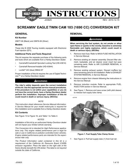
6. See Figure 1. Remove and save screw (with pilot sleeve)<br />
to release fuel supply tube clamp.<br />
is03165<br />
Figure 1. Fuel Supply Tube Clamp Screw<br />
7. See Figure 2. Pull fuel supply tube (1) from fuel rail.<br />
-J03825 1 of 10
is03166<br />
1<br />
1. Fuel supply tube<br />
2. Sealing washer<br />
3. O-ring<br />
4. Screw (with pilot sleeve)<br />
4<br />
3<br />
Figure 2. Fuel Supply Tube Assembly<br />
8. Remove sealing washer (2) and O-ring (3) from fuel supply<br />
tube. Remove second O-ring (3) from fuel rail bore. Discard<br />
sealing washer and O-rings.<br />
9. See Figure 3. Pull fuel injectors (1) with attached fuel rail<br />
from induction module. To overcome the resistance of the<br />
bottom O-ring (2) on both fuel injectors, gently rock<br />
assembly back and forth while pulling.<br />
10. Remove spring clips (3) from fuel injectors. Pull fuel<br />
injectors from fuel rail. To overcome the resistance of the<br />
top O-ring (4) on both fuel injectors, gently rock assembly<br />
back and forth while pulling.<br />
11. Disassemble engine top end, engine bottom end, crankcase,<br />
and crankshaft. Refer to appropriate ENGINE sections<br />
in Service Manual.<br />
is03167<br />
2<br />
1<br />
1. Fuel injector<br />
2. O-ring, bottom<br />
3. Clip, spring<br />
4. O-ring, top<br />
4<br />
Figure 3. Fuel Injector Assembly<br />
2<br />
3<br />
3<br />
INSTALLATION<br />
Inspect Cam Clearance<br />
A clearance problem between the new cam lobe and<br />
crankcase housing may exist on certain older model<br />
engines. Failure to maintain proper clearance could result<br />
in severe engine damage. (00391b)<br />
1. See Figure 4. Prior to starting assembly procedures, insert<br />
new cams from kit into inner needle bearings (1) located<br />
in the right side crankcase and check for a minimum of<br />
0.030 in. clearance between highest lift point of cam lobes<br />
and crankcase housing (2) with feeler gauges.<br />
NOTE<br />
If inadequate clearance is detected, crankcase housing must<br />
be machined to provide 1.060 in. Radius clearance from center<br />
of each cam bearing bore. After machining, recheck for minimum<br />
of 0.030 in. clearance.<br />
is03157<br />
1. Inner needle bearings<br />
2. Crankcase housing clearance area<br />
1<br />
2<br />
Figure 4. Inspect Cam Clearance<br />
2. Prior to engine assembly, inspect chain tensioner guides,<br />
chain guide bracket, and balance chain. Refer to inspection<br />
procedures in Service Manual.<br />
Install Flywheel Assembly<br />
See Figure 16. Install flywheel assembly (13) from kit following<br />
the instructions in the Service Manual.<br />
Remove Existing Cam Bearings<br />
NOTE<br />
Both crank and primary cam sprocket flange screws are specially<br />
hardened while the flat washers are of a special diameter<br />
and have ground surfaces. Therefore, use only the parts<br />
provided in the Cam Drive Gear Retention Kit (25533-99A)<br />
when performing this upgrade. The crank and primary cam<br />
sprocket flange screws are not interchangeable.<br />
1. Remove existing crank and primary cam sprocket flange<br />
screws and washers according to instructions in Service<br />
Manual. Discard cam drive sprocket flange screws and<br />
washers.<br />
2. Remove existing cam drive sprocket according to instructions<br />
in Service Manual.<br />
-J03825 2 of 10
3. Remove and discard existing cam bearings. Refer to<br />
ENGINE, BOTTOM END OVERHAUL Cam Support Plate,<br />
Disassembly/Assembly (Camshaft, Camshaft Bearings)<br />
section(s) of appropriate Service Manual.<br />
Install New Cam Bearings<br />
To center thrust washer, be sure o-ring is installed in relief<br />
groove. Damage to bearing cage and engine can occur if<br />
thrust washer is not centered. (00473b)<br />
NOTE<br />
If not enough of the splined shaft is exposed to install the<br />
sprocket, leave out the spacer and proceed to Step 1e. Once<br />
the bearing inner race has been started onto the machined<br />
area, remove the flange screw, washer, and sprocket, then<br />
assemble using the spacer. Repeat Step 1e to fully install<br />
bearing inner race.<br />
is03134<br />
2<br />
1. Roller bearing<br />
2. O-ring<br />
3. Thrust washer<br />
4. Bearing inner race<br />
Figure 5. Rear Cam Roller Bearing Kit<br />
1<br />
3<br />
4<br />
1. See Figure 5. Install rear cam roller bearing kit (Figure 15,<br />
item 8) onto rear camshaft.<br />
a. Install O-ring in grinding relief groove. Groove is on<br />
the splined end between the machined area and the<br />
secondary cam sprocket. Exercise caution to avoid<br />
stretching or breaking the O-ring. Since the O-ring is<br />
not sold separately, damage will require purchase of<br />
new roller bearing kit.<br />
b. Slide thrust washer down rear camshaft until centered<br />
over O-ring in grinding relief position.<br />
c. Slide bearing inner race down rear camshaft until<br />
contact is made with shoulder of machined area.<br />
d. Install primary cam sprocket spacer and sprocket on<br />
camshaft, and secure using thicker flat washer and<br />
long flange screw.<br />
e. See Figure 6. Wrap a shop rag (1) around camshaft<br />
to get a firm grip and also to protect hand from sharp<br />
edges of sprocket. Using a 9/16 in. box wrench (2),<br />
turn flange screw in a clockwise direction. Bearing<br />
inner race (3) is fully installed when it makes firm<br />
contact with the thrust washer (4).<br />
f. Verify thrust washer is locked in place and cannot<br />
be rotated. If necessary, install shaft in vise using<br />
brass jaw inserts, and further tighten flange screw<br />
until desired result is achieved.<br />
g. Remove flange screw, flat washer, sprocket, and<br />
spacer.<br />
is03135<br />
2<br />
1. Shop rag<br />
2. Box wrench, 9/16 in.<br />
3. Bearing inner race<br />
4. Thrust washer<br />
Figure 6. Install Bearing Inner Race (with O-Ring and<br />
Washer)<br />
NOTES<br />
Be aware that the front and rear cam bearings are not interchangeable.<br />
The rear cam utilizes a roller bearing while the<br />
front cam utilizes a ball bearing (See Figure 7).<br />
Bearing fit may be a light press or slightly loose fit. If deemed<br />
necessary, clean bearing O.D. and apply Loctite 243 (blue)<br />
before installation, but exercise caution to avoid getting compound<br />
on rollers or bearing I.D.<br />
-J03825 3 of 10<br />
3<br />
4<br />
1
2. Install new cam bearings into cam support plate according<br />
to the following:<br />
a. See Figure 8. Obtain the Camshaft Remover/Installer<br />
(HD-43644).<br />
b. With the secondary cam chain side facing upward,<br />
place cam support plate on support block, so that<br />
outer races of bearings are properly supported. Note<br />
that one corner of the support block is contoured to<br />
accommodate the chain guide blocks cast into the<br />
front of the support plate.<br />
c. Center new bearing over bearing bore with the<br />
lettered side up. Slide pilot shaft of bearing driver<br />
through bearing into hole of support block.<br />
d. See Figure 9. Center bearing driver under ram of<br />
arbor press. Press on driver until bearing makes firm<br />
contact with counterbore in cam support plate. Repeat<br />
Steps 2a through 2c to install second bearing.<br />
is03136<br />
1. Roller bearing, rear cam<br />
2. Ball bearing, front cam<br />
1<br />
Figure 7. Cam Bearings<br />
3. Apply Loctite 243 (blue) to threads of four bearing retainer<br />
plate screws.<br />
4. Using a T20 Torx ® drive head, secure bearing retainer<br />
plate to cam support plate.<br />
5. Tighten four bearing retainer screws to 20-30 in-lbs (2.3-<br />
3.4 Nm) in a crosswise pattern. Verify that hole in retainer<br />
plate is properly aligned with secondary cam chain oiler.<br />
is03137<br />
3<br />
1. Support block<br />
2. Bearing/pilot driver<br />
3. Camshaft driver<br />
Figure 8. Camshaft Remover/Installer<br />
2<br />
1<br />
2<br />
is03138<br />
1 2<br />
1. Bearing/pilot driver<br />
2. Bearing<br />
3. Support block<br />
Figure 9. Press Bearings into Cam Support Plate<br />
Install Camshafts<br />
1. Start camshafts into cam bearings.<br />
2. Place cam support plate back on support block, if removed.<br />
The block properly supports inner races of bearings as<br />
camshafts are installed.<br />
3. See Figure 10. Align punch marks on teeth of secondary<br />
cam sprockets (outboard faces). Using a colored marker,<br />
carefully mark the punch mark locations on the inboard<br />
side of the sprocket teeth. These marks are needed to<br />
observe proper orientation of the camshafts when they<br />
are pressed into the bearings.<br />
is03139<br />
1. Punch marks<br />
2. Front camshaft<br />
3. Rear camshaft<br />
3<br />
1<br />
Figure 10. Align Punch Marks on Teeth of Camshaft<br />
Sprockets<br />
4. Place secondary cam chain around the sprockets of both<br />
the front and rear camshafts. To maintain the original direction<br />
of rotation, be sure that the colored mark placed on<br />
the chain link during disassembly is facing opposite the<br />
cam support plate during installation.<br />
-J03825 4 of 10<br />
2<br />
3
5. Orient the camshafts so that they are positioned on<br />
opposite ends of the chain, and then verify that the colored<br />
marks placed on the inboard side of the sprocket teeth<br />
are still in alignment.<br />
6. Maintaining the position of the camshafts on the chain with<br />
the colored marks in alignment, place the sprocket ends<br />
of the camshafts into the bearings.<br />
NOTE<br />
Be sure not to mix camshafts during the press procedure. The<br />
rear camshaft, which can be identified by the splined shaft,<br />
must go into the roller bearing at the rear of the cam support<br />
plate.<br />
7. Place cup of camshaft driver over end of front camshaft<br />
only.<br />
During press procedure, keep tensioner shoe clear of chain<br />
to prevent damage to tensioner assembly. (00474b)<br />
8. Center end of front camshaft under ram and slowly apply<br />
pressure to driver just to start front camshaft into bearing<br />
I.D.<br />
Be sure rear camshaft is aligned during press procedure.<br />
Misalignment can cause inner race to catch on bearing<br />
rollers resulting in bearing damage. (00475b)<br />
9. Slowly apply pressure to driver on front camshaft, while<br />
wiggling rear camshaft as necessary to guide inner race<br />
between bearing rollers.<br />
10. When inner race on rear cam is started into roller bearing,<br />
apply pressure to driver until front camshaft is fully seated.<br />
If necessary, keep finger pressure at top of rear camshaft<br />
so that assembly remains square and inner race moves<br />
to installed position in roller bearing.<br />
11. After installing new cams, check for proper cam to cam<br />
timing using straightedge along punch marks as described<br />
in Service Manual.<br />
12. Install retaining ring from kit in groove at end of front<br />
camshaft.<br />
NOTES<br />
Inspect cam needle bearings in crankcase and replace if<br />
necessary.<br />
Replace oil pump to cam plate O-ring (Figure 15, item 2) and<br />
cam plate to crankcase O-ring (Figure 15, item 6).<br />
Install Cam Support Plate<br />
Install cam plate according to ENGINE, BOTTOM END<br />
OVERHAUL Cam Support Plate, Disassembly/Assembly<br />
instructions in applicable Service Manual.<br />
Install Rear Cam Sprocket, Crank Sprocket, and<br />
Primary Cam Chain<br />
1. Apply a thin film of clean H-D 20W50 engine oil to the<br />
splines of the rear cam.<br />
2. Install splined sprocket onto rear camshaft. Refer to<br />
ENGINE, BOTTOM END OVERHAUL Cam Support Plate,<br />
Disassembly/Assembly (Camshaft, Camshaft Bearings)<br />
section(s) in appropriate Service Manual. Use spacers<br />
provided in kit in place of those listed in Service Manual.<br />
NOTES<br />
Verify alignment at crank and primary cam sprocket punch<br />
marks as described in Service Manual.<br />
Verify alignment at crank and primary cam sprocket faces. Use<br />
spacers provided in kit to maintain alignment at plus (+) or<br />
minus (-) 0.01 in.<br />
3. See Figure 15. Use cam flange screw (12), washer (11),<br />
crank flange screw (10), and washer (9) from kit.<br />
Apply threadlocker to maintain clamp load on flange bolt.<br />
A loose flange bolt can cause engine failure, which could<br />
result in death or serious injury. (00476c)<br />
4. Install new flange screws and washers as follows:<br />
a. Verify threads are clean and free from oil then apply<br />
Loctite Primer 7649.<br />
b. Apply Loctite ® 262 (red) 94759-99 to threads of flange<br />
screws.<br />
c. Apply a thin film of clean H-D 20W50 engine oil to<br />
both sides of flat washers.<br />
d. Start flange screw with flat washer to secure crank<br />
sprocket to end of crankshaft.<br />
e. Start flange screw with flat washer to secure primary<br />
cam sprocket to end of camshaft.<br />
f. See Figure 11. Position Camshaft/Crankshaft<br />
Sprocket Locking Tool (HD-42314) between the crank<br />
and primary cam sprockets to prevent rotation. The<br />
handle of the tool is stamped "Cam" and "Crank" for<br />
proper orientation.<br />
g. Tighten crank and primary cam sprocket flange<br />
screws to 15 ft-lbs (20.3 Nm).<br />
h. Loosen each flange screw one full turn.<br />
i. Tighten crank flange screw to 24 ft-lbs (32.5 Nm) final<br />
torque value.<br />
j. Tighten primary cam sprocket flange screw to 34 ftlbs<br />
(46.0 Nm) final torque value.<br />
k. Remove sprocket locking tool and follow instructions<br />
in Service Manual for unloading primary cam chain<br />
tensioner.<br />
5. Install cam cover according to ENGINE, BOTTOM END<br />
OVERHAUL, Cam Support Plate, Disassembly/Assembly<br />
instructions in applicable Service Manual.<br />
NOTE<br />
Replace cam cover gasket (Figure 15, item 3).<br />
-J03825 5 of 10
is03140<br />
Figure 11. Camshaft/Crankshaft Sprocket Locking Tool<br />
Install Engine, Fuel Injection, and Clutch Spring<br />
1. Assemble remaining engine components. Refer to appropriate<br />
ENGINE sections in Service Manual.<br />
2. Install engine in chassis following the instructions in the<br />
Service Manual.<br />
3. See Figure 3. Apply a thin coating of clean engine oil to<br />
O-rings (2, 4) from kit on fuel injectors (1).<br />
4. Push electrical connector side of fuel injectors into fuel<br />
rail.<br />
5. See Figure 12. With the concave side toward the fuel rail,<br />
install spring clip into slot on fuel injector. In the installed<br />
position, openings (1) in side of clip engage lip (2) of fuel<br />
rail, while fork (3) at back of clip captures fuel injector tab<br />
(4).<br />
6. Rotate fuel injectors, so that the electrical connectors are<br />
on the outboard side. Push fuel injectors into the induction<br />
module bores until fuel rail tab (5) engages machined slot<br />
at top of induction module.<br />
is03168<br />
1. Opening<br />
2. Lip<br />
3. Fork<br />
4. Injector tab<br />
5. Rail tab<br />
4<br />
3<br />
Figure 12. Installation of Spring Clips<br />
5<br />
1<br />
2<br />
7. See Figure 2. Slide O-ring (3) from kit down shorter neck<br />
of the fuel supply tube (1) until it contacts the collar. Slide<br />
sealing washer (2) from kit down tube until it contacts Oring.<br />
Install second O-ring (3) in fuel rail bore.<br />
8. See Figure 1. Push fuel supply tube into fuel rail bore until<br />
clamp is seated on round step of fuel rail. Install screw<br />
(with pilot sleeve) previously removed and tighten to 90-<br />
110 in-lbs (10.2-12.4 Nm).<br />
9. Install induction module. Refer to appropriate FUEL<br />
INJECTION section in Service Manual.<br />
10. Install clutch diaphragm spring (Table 2, item 15) from kit<br />
following the instructions in the Service Manual.<br />
Install Mufflers and Air Cleaner<br />
NOTE<br />
When installing the exhaust system, first install the rear and<br />
front cylinder exhaust pipes, shields, and related components.<br />
1. See Figure 16. Install exhaust system using mufflers (1,<br />
2) from kit and parts previously removed. Refer to<br />
EXHAUST SYSTEM INSTALLATION in Service Manual.<br />
2. See Figure 13. Install air cleaner assembly using backplate<br />
(9), filter element (10), and air cleaner cover insert (11)<br />
from kit. Refer to AIR CLEANER INSTALLATION in Service<br />
Manual.<br />
Final Assembly<br />
Install maxi-fuse. Refer to MAXI-FUSE INSTALLATION in<br />
Service Manual.<br />
Recalibrate ECM<br />
You must recalibrate the ECM when installing this kit.<br />
Failure to properly recalibrate the ECM can result in severe<br />
engine damage. (00399b)<br />
Download the new ECM calibration using the Digital Technician<br />
at a <strong>Harley</strong>-<strong>Davidson</strong> dealer.<br />
-J03825 6 of 10
SERVICE PARTS<br />
Item<br />
1<br />
2<br />
3<br />
4<br />
5<br />
6<br />
7<br />
8<br />
is03171<br />
3<br />
5<br />
12<br />
4<br />
13<br />
2<br />
5<br />
8<br />
6<br />
Figure 13. Service Parts: Screamin Eagle Twin Cam <strong>103</strong> (<strong>1690</strong> <strong>CC</strong>) Conversion Kit<br />
Description (Quantity)<br />
1550 Cylinder assembly (Black)<br />
(2) (used in Kit 29877-06)<br />
Cylinder assembly (Silver) (2)<br />
(used in Kit 29876-06)<br />
Piston (2)<br />
Piston ring set (2)<br />
Piston pin (2)<br />
Piston pin circlip (4)<br />
Head gasket (2)<br />
O-ring, cylinder deck ring dowel<br />
(2)<br />
O-ring, cylinder spigot (2)<br />
Table 1. Service Parts: SE Twin Cam <strong>103</strong> (<strong>1690</strong> <strong>CC</strong>) Conversion Kit<br />
Part Number<br />
16547-99<br />
16548-99<br />
Not Sold Separately<br />
21918-99<br />
22132-99<br />
22097-99<br />
16787-99A<br />
11273<br />
11256<br />
Item<br />
9<br />
10<br />
11<br />
12<br />
13<br />
--<br />
1<br />
7<br />
11<br />
10<br />
Description (Quantity)<br />
Backplate assembly, air cleaner<br />
Element, filter<br />
Insert, air cleaner cover<br />
Cylinder head, front (black)<br />
Cylinder head, front (silver)<br />
Cylinder head, rear (black)<br />
Cylinder head, rear (silver)<br />
Piston kit (includes items 2<br />
through 5)<br />
9<br />
Part Number<br />
29697-02A<br />
29509-06<br />
29480-03<br />
17150-06<br />
17149-06<br />
17152-06<br />
17151-06<br />
22421-03<br />
Notes: Do not install O-ring (item 7) to top cylinder dowels.<br />
Refer to 2006 FLHTCUSE Parts Catalog, part number 99428-<br />
06 for individual components of cylinder head assemblies<br />
(items 11 and 12).<br />
-J03825 7 of 10
is03151b<br />
Item<br />
1<br />
2<br />
3<br />
4<br />
5<br />
6<br />
7<br />
8<br />
9<br />
6<br />
4<br />
5<br />
3<br />
9<br />
Figure 14. Service Parts: Screamin' Eagle Big Bore Stage 1 Kit<br />
Table 2. Service Parts: Screamin' Eagle Twin Cam <strong>103</strong> (<strong>1690</strong> <strong>CC</strong>) Conversion Kit<br />
Description (Quantity)<br />
Gasket, rocker cover base (2)<br />
Gasket, rocker cover top (2)<br />
Gasket, tappet cover (2)<br />
Part Number<br />
16719-99A<br />
17386-99A<br />
18635-99B<br />
O-ring, middle push rod cover (4) 11132<br />
O-ring, lower push rod cover (4)<br />
O-ring, upper push rod cover (4)<br />
O-ring, rocker arm support (2)<br />
Bolt (4)<br />
Breather assembly<br />
11145<br />
11293<br />
11270<br />
4400<br />
17025-03A<br />
7<br />
Item<br />
10<br />
11<br />
12<br />
13<br />
14<br />
15<br />
--<br />
8<br />
2<br />
10<br />
1<br />
Description (Quantity)<br />
Baffle assembly (2)<br />
Product information label (Not<br />
Shown)<br />
Seal, exhaust (Not Shown)<br />
Seal, EFI intake (2) (Not Shown)<br />
Seal, map sensor (Not Shown)<br />
Spring, clutch diaphragm (Not<br />
Shown)<br />
Breather assembly (includes items<br />
8 through 10)<br />
Part Number<br />
26500002<br />
Not Sold Separately<br />
17048-98<br />
26995-86B<br />
11291<br />
37951-98<br />
17025-03A<br />
-J03825 8 of 10
Item<br />
1<br />
2<br />
3<br />
4<br />
5<br />
6<br />
7<br />
8<br />
9<br />
10<br />
11<br />
is03176<br />
8<br />
12<br />
4<br />
11<br />
7<br />
1<br />
5<br />
10<br />
2<br />
9<br />
6<br />
1<br />
20<br />
7<br />
Figure 15. Service Parts: Screamin' Eagle Twin Cam <strong>103</strong> (<strong>1690</strong> <strong>CC</strong>) Conversion Kit<br />
Table 3. Service Parts: Screamin' Eagle Twin Cam <strong>103</strong> (<strong>1690</strong> <strong>CC</strong>) Conversion Kit<br />
Description (Quantity)<br />
Retaining ring, camshaft (2)<br />
O-ring, oil pump to cam plate<br />
Gasket, cam cover<br />
Retaining ring, camshaft<br />
Ball bearing, front camshaft<br />
1<strong>103</strong>1<br />
11286<br />
Part Number<br />
25244-99A<br />
11494<br />
8990A<br />
O-ring, cam plate to crankcase (2) 11301<br />
Camshaft kit<br />
Roller bearing kit, rear camshaft<br />
Washer (crank) (2)<br />
Capscrew, flanged (crank)<br />
Washer (rear cam)<br />
25376-03<br />
8983<br />
Not Sold Separately<br />
Not Sold Separately<br />
6294<br />
19<br />
Item<br />
12<br />
13<br />
14<br />
15<br />
16<br />
17<br />
18<br />
19<br />
20<br />
21<br />
3<br />
18<br />
17<br />
16<br />
Description (Quantity)<br />
Capscrew, flanged (rear cam)<br />
Flywheel assembly<br />
Seal, main bearing oil<br />
Washer, thrust sprocket shaft<br />
main bearing<br />
Bearing, main (2)<br />
Retaining ring, internal<br />
O-ring, crankcase ring dowel (2)<br />
O-ring, piston cooling (2)<br />
O-ring, CPS<br />
Loctite 262 (red), 0.5 ml packet<br />
(Not Shown)<br />
13<br />
996<br />
15<br />
14<br />
Part Number<br />
23740-03B<br />
12068<br />
8972<br />
24604-00D<br />
35114-02<br />
26432-76A<br />
11140<br />
11289A<br />
Not Sold Separately<br />
Notes: Items 9 and 10 are only available as part of Cam Drive<br />
Retention Kit 25533-99A. Loctite (item 21) is only available in<br />
6 ml tube, part number 94759-99.<br />
-J03825 9 of 10
Item<br />
1<br />
2<br />
3<br />
4<br />
5<br />
6<br />
is03169<br />
5<br />
1<br />
Figure 16. Service Parts: Screamin' Eagle Twin Cam <strong>103</strong> (<strong>1690</strong> <strong>CC</strong>) Conversion Kit<br />
Table 4. Service Parts: Screamin' Eagle Twin Cam <strong>103</strong> (<strong>1690</strong> <strong>CC</strong>) Conversion Kit<br />
Muffler assembly, R.H. (with end caps)<br />
Muffler assembly, L.H. (with end caps)<br />
O-ring, fuel supply tube (2)<br />
Sealing washer, fuel supply tube<br />
Fuel injector (2)<br />
Element, filter (Not Shown)<br />
Description (Quantity)<br />
2<br />
3<br />
4<br />
3<br />
66077-06<br />
66012-06<br />
27680-06<br />
27681-06<br />
27709-06<br />
29509-06<br />
Part Number<br />
-J03825 10 of 10