
Create successful ePaper yourself
Turn your PDF publications into a flip-book with our unique Google optimized e-Paper software.
<strong>SmartScan</strong><br />
<strong>User's</strong> <strong>Manual</strong><br />
for <strong>SmartScan</strong> 25/50
ii<br />
<strong>SmartScan</strong> User’s <strong>Manual</strong><br />
Important Notice<br />
This manual is delivered subject to the following conditions<br />
and restrictions:<br />
This manual contains proprietary information belonging<br />
to Solid Applied Technologies Ltd. Such information is<br />
supplied solely for the purpose of assisting explicitly and<br />
properly authorized users of <strong>SmartScan</strong>.<br />
No part of its contents may be used for any other<br />
purpose, disclosed to any person or firm or reproduced<br />
by any means, electronic or mechanical, without the<br />
express prior written permission of Solid Technologies<br />
Ltd.<br />
The text and graphics are for the purpose of illustration<br />
and reference only. The specifications on which they are<br />
based are subject to change without notice.<br />
Information in this document is subject to change without<br />
notice. Corporate and individual names and data used in<br />
examples herein are fictitious unless otherwise noted.<br />
Copyright © 2004. All rights reserved.<br />
<strong>SmartScan</strong>® is a trademark of Solid Applied Technologies<br />
Ltd.<br />
Other company and brand products and service names are<br />
trademarks or registered trademarks of their respective<br />
holders.<br />
Date Revision Software Version Catalog Number<br />
June, 2004 2.1 5.06 - 5.07<br />
2.05 - 2.06<br />
680003C
Safety Guidelines<br />
Safety Guidelines<br />
Please review the following points before installing and<br />
operating the <strong>SmartScan</strong> system.<br />
<strong>SmartScan</strong> must be installed, connected and operated<br />
according to the instructions in this <strong>Manual</strong>.<br />
If installed incorrectly or used for applications for which<br />
it is not intended, application-related dangers may arise.<br />
Only qualified personnel are authorized to install and<br />
operate <strong>SmartScan</strong>.<br />
When <strong>SmartScan</strong> is reopened, ensure that you replace<br />
the O-ring, in order that the unit will remain sealed (for<br />
IP67 units). The O-ring is suitable for one use only.<br />
Modifications and repairs to <strong>SmartScan</strong> are permissible<br />
only when the manufacturer expressly approves them.<br />
iii
iv<br />
<strong>SmartScan</strong> User’s <strong>Manual</strong><br />
Table of Contents<br />
Chapter 1: Introducing <strong>SmartScan</strong>............................................... 1<br />
Sensor Dimensions ........................................................................................ 6<br />
<strong>SmartScan</strong> 25 Specifications .......................................................................... 8<br />
<strong>SmartScan</strong> 50 Specifications ........................................................................ 12<br />
Sensor Recommendations............................................................................ 15<br />
Sensor Cable Recommendations.................................................................. 16<br />
Chapter 2: Installing <strong>SmartScan</strong>................................................. 19<br />
Precautions ................................................................................................. 19<br />
Installing the <strong>SmartScan</strong> Sensor .................................................................. 20<br />
Threading Options................................................................................... 21<br />
Sensor Positioning ................................................................................... 24<br />
Installing the Sensor via an Extension Pipe .............................................. 26<br />
Wiring the <strong>SmartScan</strong> Unit ......................................................................... 28<br />
Wiring the Sensor Cable.......................................................................... 29<br />
Wiring the Monitoring Cables.................................................................. 31<br />
Wiring the Relays Cable .......................................................................... 32<br />
Wiring VDC Power Cable........................................................................ 33<br />
Wiring VAC Power Cable........................................................................ 33<br />
<strong>SmartScan</strong> 25 Intrensically Safe Connections........................................... 34<br />
Chapter 3: Basic Setup............................................................... 40<br />
Using the <strong>SmartScan</strong> Function Buttons ....................................................... 42<br />
Modifying Numerical Values................................................................... 43
Table of Contents<br />
Menu and Version Selection........................................................................ 44<br />
Accessing the Main Menu ........................................................................... 45<br />
Using the Main Menu.............................................................................. 46<br />
Default Screen............................................................................................. 47<br />
Setting Main Menu Options ........................................................................ 49<br />
Setting the Indication Mode..................................................................... 50<br />
Setting the Measurement Unit.................................................................. 52<br />
Setting the Relay Values for <strong>SmartScan</strong> 50............................................... 54<br />
Setting the Relay Values for <strong>SmartScan</strong> 25............................................... 63<br />
Setting the 20 mA/4 mA Levels ................................................................ 65<br />
Setting the Flow Measurements ............................................................... 66<br />
Setting the Tank Height............................................................................ 67<br />
Setting the Application Type.................................................................... 69<br />
Setting the Operation Modes ................................................................... 70<br />
Setting the Sensor Offset .......................................................................... 72<br />
Setting the Scan Distance Values ............................................................. 74<br />
Clearing the Scan Distance Values .......................................................... 77<br />
Viewing Processor Information ................................................................... 77<br />
Chapter 4: <strong>SmartScan</strong> Open Channels........................................79<br />
Selecting the Flow Measurement Settings ................................................... 79<br />
Open Channels Flow Measurements ........................................................... 81<br />
Flume/Weir Types.................................................................................... 82<br />
European Standard .................................................................................. 83<br />
Rectangular Suppressed Sharp-crested Weir (Type 1) .............................. 83<br />
Rectangular Contracted Sharp-crested Weir (Type 2)............................... 84<br />
Trapezoidal (Cipolletti) Sharp-crested Weir (Type 3)................................ 85<br />
V-notch (Triangular) Sharp-crested Weir (Type 4) .................................... 86<br />
v
vi<br />
<strong>SmartScan</strong> User’s <strong>Manual</strong><br />
Khafagi-Venturi Flume (Type 5) ............................................................... 87<br />
Parshall Flume (Type 6) ........................................................................... 88<br />
Palmer Bowls Flume Trapezoidal Throat Cross-selection (Type 7)........... 89<br />
H Flume (Type 8)..................................................................................... 90<br />
Neyrpic Venturi Flume/Long-base Weir (Type 9)..................................... 91<br />
American Standard ................................................................................. 93<br />
Rectangular Suppressed Sharp-crested Weir (Type 1) .............................. 93<br />
Rectangular Contracted Sharp-crested Weir (Type 2)............................... 94<br />
Trapezoidal (Cipolletti) Sharp-crested Weir (Type 3) ............................... 95<br />
V-notch (Triangular) Sharp-crested Weir (Type 4).................................... 96<br />
Parshall Flume (Type 5) ........................................................................... 97<br />
Palmer Bowls Flume Trapezoidal Throat Cross-selection (Type 6)........... 98<br />
H Flume (Type 7)..................................................................................... 99<br />
Leopold Lagco Flume (Type 8) .............................................................. 100<br />
Chapter 5: Additional Features ................................................ 101<br />
Accessing the Additional Menu................................................................. 102<br />
Setting Additional Menu Options.............................................................. 103<br />
Selecting an Indication .......................................................................... 104<br />
<strong>Manual</strong>ly Inserting Strapping Table Values ............................................ 106<br />
Semi-automatic Inserting of Strapping Table Values .............................. 108<br />
Inserting a Coefficient for Readings ....................................................... 110<br />
Erasing Strapping Table Values.............................................................. 112<br />
Configuring Height for a Cone............................................................... 113<br />
Defining 22mA/3.7mA Signal Error Messages........................................ 114<br />
Entering Factor for Gas Compensation in <strong>SmartScan</strong> 25 ........................ 116
Table of Contents<br />
Chapter 6: Diameter Mode Setup.............................................118<br />
Using Diameter Sum Option ..................................................................... 123<br />
Chapter 7: Troubleshooting <strong>SmartScan</strong> ....................................125<br />
Appendix A: <strong>SmartScan</strong> Ranges ................................................128<br />
Appendix B: Gas Factor Table ..................................................130<br />
Index........................................................................................133<br />
vii
viii<br />
<strong>SmartScan</strong> User’s <strong>Manual</strong><br />
Table of Figures<br />
Figure 1: Front View of <strong>SmartScan</strong> ......................................................... 3<br />
Figure 2: Side View of <strong>SmartScan</strong> ........................................................... 3<br />
Figure 3: Wall-mount Plate..................................................................... 4<br />
Figure 4: Back View of <strong>SmartScan</strong> with Wall-mount Plate...................... 4<br />
Figure 5: Panel Mount ............................................................................ 5<br />
Figure 6: Top View of <strong>SmartScan</strong> with Panel-mount Installation............. 5<br />
Figure 7: <strong>SmartScan</strong> Sensor Dimensions ................................................. 6<br />
Figure 8: Sensor Threading Options...................................................... 21<br />
Figure 9: Sensor Positioning.................................................................. 24<br />
Figure 10: Extension Pipe Installation ................................................... 26<br />
Figure 11: Electrical Unit...................................................................... 28<br />
Figure 12: <strong>SmartScan</strong> Main Menu Screen ............................................. 41<br />
Figure 13: <strong>SmartScan</strong> Default Screen.................................................... 47<br />
Figure 14: Tank Height ......................................................................... 74<br />
Figure 15: Scan Distance Process.......................................................... 77<br />
Figure 16: Rectangular Suppressed Sharp-crested Weir ........................ 83<br />
Figure 17: Rectangular Contracted Sharp-crested Weir ........................ 84<br />
Figure 18: Trapezoidal (Cipolletti) Sharp-crested Weir......................... 85<br />
Figure 19: V-notch (Triangular) Sharp-crested Weir ............................. 86<br />
Figure 20: Khafagi-Venturi Flume ......................................................... 87<br />
Figure 21: Parshall Flume ..................................................................... 88<br />
Figure 22: Palmer Bowls Flume Trapezoidal Throat Cross-selection ..... 89
Table of Figures<br />
Figure 23: H Flume............................................................................... 90<br />
Figure 24: Neyrpic Venturi Flume ........................................................ 91<br />
Figure 25: Long-base Weir.................................................................... 92<br />
Figure 26: Leopold-Lagco Flume......................................................... 100<br />
Figure 27: Cone Height ...................................................................... 113<br />
Figure 28: Measuring Rolls Diameter ................................................. 118<br />
ix
Introducing <strong>SmartScan</strong><br />
CHAPTER 1<br />
1<br />
Chapter 1<br />
Introducing <strong>SmartScan</strong><br />
<strong>SmartScan</strong> is a non-contact, ultrasonic, continuous-level<br />
measurement instrument that is able to provide accurate<br />
measurements for both liquids and solids, while<br />
automatically compensating for changes in temperature and<br />
other environmental conditions. <strong>SmartScan</strong> is designed for<br />
applications such as process tanks, storage vessels, open air<br />
piles, open channels, and so on.<br />
<strong>SmartScan</strong> is a four-wire, low-voltage device, and is available<br />
with a customized graphic LCD display. <strong>SmartScan</strong> has two<br />
major components, the main control unit and the sensor<br />
(connected via a cable).<br />
Main (electronic) control unit: If required, this<br />
component can be optionally wall mounted, using a<br />
wall-mount plate, or panel mounted. To ensure proper<br />
operation, the unit must be installed up to 200 m (656 ft)<br />
from the sensor and 100m (328 ft) for EX sensors.<br />
Sensor and data cable: The sensor is supplied with the<br />
data cable attached. See description of available cable<br />
lengths in Page 16.<br />
The installation procedure and wiring connections for<br />
these components are described in Chapter 2, Installing<br />
<strong>SmartScan</strong>.
2<br />
<strong>SmartScan</strong> User’s <strong>Manual</strong><br />
The <strong>SmartScan</strong> product line comprises two families,<br />
<strong>SmartScan</strong> 25 (25 KHz) and <strong>SmartScan</strong> 50 (50 KHz), each<br />
with its own models (as listed below). A variety of sensors are<br />
available for <strong>SmartScan</strong> 25, suitable for different ranges.<br />
<strong>SmartScan</strong> 25:<br />
<strong>SmartScan</strong> L for liquid (Standard Range/Long Range)<br />
<strong>SmartScan</strong> S for solid (Standard Range/Long Range)<br />
<strong>SmartScan</strong> O for open channel (Standard Range/Long<br />
Range)<br />
<strong>SmartScan</strong> R for Liquid short Range<br />
<strong>SmartScan</strong> 50:<br />
<strong>SmartScan</strong> L for liquid<br />
<strong>SmartScan</strong> S for solid<br />
<strong>SmartScan</strong> O for open channel<br />
<strong>SmartScan</strong> D for diameter
Introducing <strong>SmartScan</strong><br />
CHAPTER 1<br />
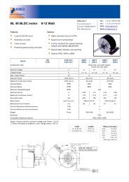
The following diagrams show the front and side views of<br />
<strong>SmartScan</strong>, and its dimensions in millimeters:<br />
Figure 1: Front View of<br />
<strong>SmartScan</strong><br />
Figure 2: Side View of<br />
<strong>SmartScan</strong><br />
3
4<br />
<strong>SmartScan</strong> User’s <strong>Manual</strong><br />
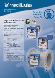
The following schematic diagrams show the wall-mount and<br />
panel-mount options, with the dimensions in millimeters:<br />
Figure 3: Wall-mount Plate<br />
Figure 4: Back View of<br />
<strong>SmartScan</strong> with Wall-mount<br />
Plate
Figure 5: Panel Mount<br />
Introducing <strong>SmartScan</strong><br />
CHAPTER 1<br />
Figure 6: Top View of <strong>SmartScan</strong> with Panel-mount Installation<br />
5
6<br />
<strong>SmartScan</strong> User’s <strong>Manual</strong><br />
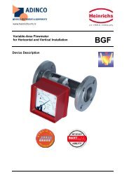
Sensor Dimensions<br />
25 kHz Standard<br />
Range<br />
25 kHz Long<br />
Range Sensor<br />
Figure 7: <strong>SmartScan</strong> Sensor Dimensions
50 kHz Sensor<br />
Figure 7 (Cont.): <strong>SmartScan</strong> Sensor Dimensions<br />
Introducing <strong>SmartScan</strong><br />
CHAPTER 1<br />
7
8<br />
<strong>SmartScan</strong> User’s <strong>Manual</strong><br />
<strong>SmartScan</strong> 25 Specifications<br />
Measuring Ranges<br />
Accuracy<br />
Short Range 25R 0.6 m to 10 m (2 ft to 32 ft)<br />
Standard Range 25S<br />
25L, 25O<br />
Long Range 25S,<br />
25L, 25O<br />
Hazardous Installation version:<br />
0.6 m to 20 m (2 ft to 64 ft)<br />
0.6 m to 25 m (2 ft to 82 ft)<br />
0.6 m to 30m (2 ft to 98 ft)<br />
0.6 m to 40 m (2 ft to 131ft)<br />
Short Range* 25R 0.6 m to 10 m (2 ft to 32 ft)<br />
Standard Range 25S<br />
25L, 25O<br />
Long Range 25S,<br />
25L, 25O<br />
<strong>SmartScan</strong> 25L, 25S, 25O,<br />
25R<br />
0.6 m to 15 m (2 ft to 49 ft)<br />
0.6 m to 20 m (2 ft to 64 ft)<br />
0.6 m to 20 m (2 ft to 64 ft)<br />
0.6 m to 25 m (2 ft to 82 ft)<br />
Resolution 1 mm (0.04")<br />
Ambient temp’ compensation Automatic<br />
0.25% of the measuring range<br />
0.30% of the measuring range
Mechanical Specifications<br />
Introducing <strong>SmartScan</strong><br />
CHAPTER 1<br />
Enclosure IP 65/67 (NEMA X4/X6), plastic ABS,<br />
wall mount/panel mount<br />
Pollution degree 2 (as per IEC61010)<br />
Insulation category II (as per IEC61010)<br />
Mechanical fitting Gland connection Pg9<br />
Conduit connection 1/2" NPT<br />
Conduit connection M20 x 2.5<br />
Temperature range DC model: -40°C to 60°C (-40°F to 140°F)<br />
AC model: -20°C to 60°C (-4°F to 140°F)<br />
Dimensions 272 mm x 200 mm x 85 mm<br />
(10.7" x 7.9" x 3.3")<br />
Weight 1.6 kg (3.5 lb.)<br />
Sensors<br />
Wetted parts PolyProp (PP) (PVDF: optional),<br />
SS or coated aluminum (ECTFE / Halar)<br />
Signal power between<br />
unit and sensor<br />
Min. range: 4Vp-p<br />
Max. range: 80Vp-p<br />
Operating pressure Atmospheric<br />
Operating temperature -40°C to 80°C (-40°F to 176°F)**<br />
Mounting 1" BSP or 2" BSP, 1" NPT or 2" NPT<br />
Transducer 25 kHz<br />
9
10<br />
<strong>SmartScan</strong> User’s <strong>Manual</strong><br />
Hazardous Installation version:<br />
Max. cable length between unit and<br />
barriers<br />
between sensor and barriers<br />
Electrical Specifications<br />
Display Customized LCD<br />
Up to 25m (82ft)<br />
Up to 75m (246ft)<br />
Supply 18 to 30 VDC (0.25 A max),<br />
(external fuse: Slow Blow 1A T type***) or<br />
100 — 230 VAC, 50/60Hz, 70mA Max.<br />
Outputs 4-20 mA, 750 Ω load @ 24 VDC<br />
Interface RS-232 or RS-485<br />
Protocol Modbus — RTU<br />
Relays 5 independent SPDT****
Certifications<br />
CE - EMC, FM — Safety, FCC<br />
Transmitter:<br />
Introducing <strong>SmartScan</strong><br />
CHAPTER 1<br />
FM, CSA*, (Classified): Non Incendive, Class I,II,III/ Division 2/<br />
Groups ABCDFG/T4<br />
Sensor:<br />
ATEX: II 1G, EEx ia IIC T4 (Ta = -40°C to +70°C)<br />
EEx m IIC T4*<br />
FM, CSA*, (Classified):<br />
Intrinsically safe Class I,II,III/Division 1/ Groups ABCDEFG/T4<br />
Non Incendive, Class I,II,III/Division 2/ Groups ABCDFG/T4<br />
Characteristics<br />
Level, distance, flow, volume, kilograms and totalization.<br />
* Consult factory<br />
** IS model temp’ range is 70°C<br />
*** Recommended type: 0034.3117 Schurter<br />
**** Up to 6 relays available in multi-sensor models<br />
11
12<br />
<strong>SmartScan</strong> User’s <strong>Manual</strong><br />
<strong>SmartScan</strong> 50 Specifications<br />
Measuring Ranges<br />
Accuracy<br />
<strong>SmartScan</strong> 50L 0.4 m to 12 m (1.3 ft to 39.4 ft)<br />
<strong>SmartScan</strong> 50S 0.4 m to 8.5 m (1.3 ft to 28 ft)<br />
<strong>SmartScan</strong> 50D 0.5 m to 3 m (1.6 ft to 9.8 ft)<br />
<strong>SmartScan</strong> 50O 0.4 m to 12 m (1.3 ft to 39.4 ft)<br />
<strong>SmartScan</strong> 50L 0.2% of the measuring range<br />
<strong>SmartScan</strong> 50S 0.25% of the measuring range<br />
<strong>SmartScan</strong> 50D 0.1% of the measuring range<br />
<strong>SmartScan</strong> 50O 0.2% of the measuring range<br />
Mechanical Specifications<br />
Enclosure IP 65/67 (NEMA X4/X6), plastic ABS,<br />
wall mount/panel mount<br />
Pollution degree 2 (as per IEC61010)<br />
Insulation category II (as per IEC61010)<br />
Mechanical fitting Gland connection Pg9<br />
Conduit connection 1/2" NPT<br />
Conduit connection M20 x 2.5<br />
Temperature range DC model: -40° C to 60° C (-40° F to 140° F)<br />
AC model: -20° C to 60° C (-4° F to 140° F)<br />
Dimensions 272 mm x 200 mm x 85 mm
Sensors<br />
(10.7" x 7.9" x 3.3")<br />
Weight 1.6 kg (3.5 lb.)<br />
Introducing <strong>SmartScan</strong><br />
CHAPTER 1<br />
Wetted parts PolyProp (PP) (PVDF: optional),<br />
glass reinforced epoxy<br />
Operating pressure Atmospheric<br />
Operating temperature<br />
Signal power between<br />
unit and sensor<br />
13<br />
-40° C to 100° C (-40° F to 212° F)<br />
Min. range: 4Vp-p<br />
Max. range: 400Vp-p<br />
Mounting 1" BSP, 1" NPT<br />
Transducer 50 kHz<br />
Maximum sensor cable<br />
to unit distance<br />
Electrical Specifications<br />
200 m (656 ft)<br />
Display Customized LCD<br />
Supply 18 to 30 VDC (0.25 A max)<br />
(external fuse: Slow Blow 1A T type*) or<br />
100 — 230 VAC, 50/60Hz, 70mA Max.<br />
Outputs 4-20 mA, 750 Ω load @ 24 VDC<br />
Interface RS-232 or RS-485<br />
Protocol Modbus — RTU**<br />
Relays 5 independent SPDT***<br />
* Recommended type: 0034.3117 Schurter<br />
** Consult factory<br />
*** Up to 6 relays available in multi-sensor models
14<br />
<strong>SmartScan</strong> User’s <strong>Manual</strong><br />
Certifications<br />
CE - EMC, FM — Safety, FCC<br />
Characteristics<br />
Transmitter: FM, CSA*, (Classified): Non Incendive, Class<br />
I,II,III/ Division 2/ Groups ABCDFG/T4<br />
Sensor: 3A, *EEx m IIC T5<br />
Level, distance, flow, volume, kilograms, totalization and<br />
diameter.
Sensor Recommendations<br />
25 kHz Sensor Recommendations<br />
Material Description<br />
Introducing <strong>SmartScan</strong><br />
CHAPTER 1<br />
Stainless steel* For liquid applications.<br />
High resistance in highly acidic and alcoholic<br />
environments.<br />
Less sensitive to echoes (in solid applications).<br />
Coated<br />
aluminum<br />
(Halar®ECTFE)<br />
* Consult factory<br />
15<br />
Designed for complex environments with<br />
problematic echoes, such as non-conductive<br />
vapors, liquids and solids.<br />
Good performance in problematic applications.<br />
Usable in highly acidic or alcoholic<br />
environments. High sensitivity to echoes.<br />
50 kHz Sensor Recommendations<br />
Material Description<br />
Glass<br />
reinforced<br />
epoxy<br />
For liquid and solid applications (not<br />
recommended for dusty environments.)<br />
High resistance in highly acidic and alcoholic<br />
environments. Used for rapid response.
16<br />
<strong>SmartScan</strong> User’s <strong>Manual</strong><br />
Sensor Cable Lengths<br />
All sensors are supplied with either pre cut cable or with flexible<br />
cable.<br />
Sensor cable specifications: 4 wires, 0.75 mm 2 overall shielded,<br />
compatible with HELUKABEL P.N.16028 (www.helukabel.de).<br />
NOTE:<br />
It is recommended to use a connector when cutting/adding sensor cables (both<br />
precut and flexible sensors.)<br />
For unclassified sensors use BULGIN MINI BUCCANEER® connector (P/N<br />
PX0800/1 or Solid AT' P/N ACC-I).<br />
Pre cut cable (Non Hazardous)<br />
Pre cut sensor cables can be modified to fit longer and shorten<br />
length than the one that was ordered. For example, if you ordered<br />
a sensor for the <strong>SmartScan</strong> 25 with a 5m/16.4ft cable, you will be<br />
able to modify it to a range between 5m/16.4ft to 50m/164ft, or if<br />
you ordered a sensor for the <strong>SmartScan</strong> 50 with 35m/114ft cable<br />
you will be able to modify it to fit a range between 5m/16.4ft to<br />
100m/328ft. The modifications in the cable length can be made<br />
according to following tables:<br />
NOTE:<br />
Sensor cable should not be cut below minimum of 5 meters (16.4 ft) length.<br />
For EX sensors, use fixed length cables only.
25 kHz Sensor Cable (CE)<br />
Introducing <strong>SmartScan</strong><br />
CHAPTER 1<br />
50KHz sensor pre cut cable Can be changed to a range of<br />
length (m/ft)<br />
(m/ft)<br />
5m/16.4ft 5m/16.4ft to 50m/164ft<br />
15m/49.21ft 5m/16.4ft to 50m/164ft<br />
25m/82ft 5m/16.4ft to 50m/164ft<br />
35m/114ft 5m/16.4ft to 50m/164ft<br />
50m/164ft 5m/16.4ft to 50m/164ft<br />
75m/246ft 50m/164ft to 100m/328ft<br />
100m/328ft 50m/164ft to 100m/328ft<br />
125m/410ft 100m/328ft to 150m/492ft<br />
150m/492ft 100m/328ft to 150m/492ft<br />
175m/574ft 100m/328ft to 200m/656ft<br />
200m/656ft 100m/328ft to 200m/656ft<br />
50 kHz Sensor Cable (CE)<br />
50KHz sensor pre cut cable Can be changed to a range of<br />
length (m/ft)<br />
(m/ft)<br />
5m/16.4ft 5m/16.4ft to 100m/328ft<br />
15m/49.21ft 5m/16.4ft to 100m/328ft<br />
25m/82ft 5m/16.4ft to 100m/328ft<br />
35m/114ft 5m/16.4ft to 100m/328ft<br />
50m/164ft 5m/16.4ft to 100m/328ft<br />
75m/246ft 5m/16.4ft to 100m/328ft<br />
100m/328ft 5m/16.4ft to 100m/328ft<br />
125m/410ft 100m/328ft to 200m/656ft<br />
150m/492ft 100m/328ft to 200m/656ft<br />
175m/574ft 100m/328ft to 200m/656ft<br />
200m/656ft 100m/328ft to 200m/656ft<br />
17
18<br />
<strong>SmartScan</strong> User’s <strong>Manual</strong><br />
Flexible cable<br />
Flexible sensor cables are supplied with 5m/16.4ft loose-end<br />
cable. However, they can be modified to fit longer length than<br />
5m/16.4ft. The modifications in the cable length can be made<br />
according to following tables:<br />
25 kHz Sensor Cable<br />
25KHz sensor cable length (m/ft)<br />
5-50m / 16.4-164ft<br />
50-100m / 49.21-328ft<br />
100-150m / 328-492ft<br />
150-200m / 492-656ft<br />
50 kHz Sensor Cable<br />
Can be changed to a range of (m/ft)<br />
5m/16.4ft to 100m/328ft<br />
100m/328ft to 200m/656ft<br />
NOTE:<br />
Any cable length beyond 100m/328ft, may reduce the measuring range.<br />
Fixed cable length for EX Units<br />
25 kHz Sensor<br />
Fixed Cable Length (m/ft)<br />
25m/82ft<br />
50m/164ft<br />
75m/246ft<br />
100m/328ft
Precautions<br />
Installing <strong>SmartScan</strong><br />
CHAPTER 2<br />
19<br />
Chapter 2<br />
Installing <strong>SmartScan</strong><br />
Ensure that the <strong>SmartScan</strong> components are mounted in an area<br />
that meets the stated temperature, pressure and technical<br />
specifications.<br />
Ensure that high-voltage sources or cables are at least 1 m/3.28ft<br />
away from the sensor and its cable.<br />
Use round cables with minimum diameter of 6-7 mm to ensure<br />
that the unit remains sealed (IP65/67).<br />
Ensure that cables are routed correctly and tightened along walls<br />
or pipes.<br />
Ensure that all cables are overall shielded (sensor cable, interface<br />
cable, power cable and current cable).<br />
Installation and operation of this product should be performed,<br />
according to the Product User <strong>Manual</strong> and Product Certification.<br />
Otherwise the use of this product is prohibited.
20<br />
<strong>SmartScan</strong> User’s <strong>Manual</strong><br />
Installing the <strong>SmartScan</strong> Sensor<br />
The following procedures describe sensor installation using<br />
1" or 2" threading and a correlating locking nut. The<br />
installation procedure is the same whether the sensor is<br />
mounted directly on the tank or mounted on a pipe.<br />
NOTE:<br />
If applicable, you can also install the sensor by screwing it directly<br />
into the tank or pipe threading. Ensure that the tank/pipe threading<br />
matches the sensor threads.<br />
To install the sensor using 1" threading:<br />
1 Open the required tank (or pipe).<br />
2 Feed the free end of the sensor cable from the inside of<br />
the tank through the aperture at the top of the tank, until<br />
the sensor is pulled taut against the ceiling. The threaded<br />
end of the sensor should protrude from the top of the<br />
tank.<br />
3 Spread silicon grease around the threading to seal against<br />
leakage (you can also use a Teflon band).<br />
4 Thread the free end of the sensor cable through a 1"<br />
locking nut (not supplied with the <strong>SmartScan</strong> unit). Bolt<br />
the sensor into place by securing the nut to the sensor<br />
thread protruding from the top of the tank.<br />
NOTE:<br />
Tighten the nut by hand only. When tightening the nut, hold the<br />
lower part of the sensor.<br />
5 Wire the sensor cable to the main <strong>SmartScan</strong> unit, as<br />
described on page 29.
Installing <strong>SmartScan</strong><br />
CHAPTER 2<br />
To install the sensor using 2" threading<br />
(25 kHz standard range sensor):<br />
Follow the procedure described on the previous page for<br />
1" threading, using a 2" locking nut with the 2" BSP/NPT<br />
sensor threading.<br />
Threading Options<br />
<strong>SmartScan</strong> sensors are available in BSP or NPT thread types.<br />
The 50 kHz sensor can be installed using 1" threading.<br />
The 25 kHz sensors can be installed using 1" or 2" threading.<br />
(Refer to Figure 2: <strong>SmartScan</strong> Sensor Dimensions in<br />
Chapter 1, Introducing <strong>SmartScan</strong>.)<br />
1" BSP/1" NPT<br />
Threading for<br />
25 kHz Sensor<br />
(Standard<br />
Range)<br />
Figure 8: Sensor Threading Options<br />
21
22<br />
<strong>SmartScan</strong> User’s <strong>Manual</strong><br />
1" BSP/1" NPT<br />
Threading for<br />
50 kHz Sensor<br />
1" BSP/1" NPT<br />
Threading for<br />
25 kHz Sensor<br />
(Long Range)<br />
Figure 8 (Cont.): Sensor Threading Options
2" BSP/2" NPT<br />
Threading for<br />
25 kHz Sensor<br />
(Standard<br />
Range)<br />
Installing <strong>SmartScan</strong><br />
CHAPTER 2<br />
Figure 8 (Cont.): Sensor Threading Options<br />
NOTES:<br />
When installing a thread-free flange mounted unit, you will need a 1" or<br />
2" locking nut (depending on the thread type used) to secure the sensor<br />
to the tank. The nut can be purchased separately.<br />
When installing a threaded flange, ensure that it matches the <strong>SmartScan</strong><br />
threads.<br />
23
24<br />
<strong>SmartScan</strong> User’s <strong>Manual</strong><br />
Sensor Positioning<br />
When installing the sensor, ensure that it is:<br />
Mounted above the<br />
dead-zone area<br />
(blocking distance).<br />
NOTE:<br />
If the device enters the<br />
dead zone, it will not<br />
measure correctly.<br />
Positioned at least 0.5<br />
m (1.64 ft) away from<br />
the tank walls.<br />
Figure 9: Sensor Positioning
Perpendicular to the<br />
surface of the target.<br />
NOTE:<br />
Even the slightest<br />
difference in angle may<br />
affect echo quality.<br />
Install the sensor as far<br />
as possible from noisy<br />
areas, such as a filling<br />
inlet.<br />
Installing <strong>SmartScan</strong><br />
CHAPTER 2<br />
Figure 9 (Cont.): Sensor Positioning<br />
25<br />
Filling inlet
26<br />
<strong>SmartScan</strong> User’s <strong>Manual</strong><br />
Installing the Sensor via an Extension Pipe<br />
If the level of the measured surface falls within the dead-zone<br />
area, you should use an extension pipe to mount the sensor.<br />
When using an extension pipe, ensure that:<br />
The sensor is positioned in<br />
the center of the pipe.<br />
The pipe extension is<br />
parallel to the side/tank<br />
walls.<br />
The tank should be empty<br />
to allow tracking of false<br />
echoes.<br />
The internal pipe diameter<br />
is at least 3" and 4" wide.<br />
Figure 10: Extension Pipe Installation
Installing <strong>SmartScan</strong><br />
CHAPTER 2<br />
When installing the sensor with an extension pipe, follow<br />
these specifications:<br />
25 kHz and 50 kHz Sensor<br />
Pipe Length Internal Pipe Diameter<br />
0.50 m (1.64 ft) 3"/4"<br />
NOTES:<br />
We advise you to consult with your local distributor prior to the installation.<br />
It is essential to run scan distance function during the installation process.<br />
It is recommended to use pipes made of PVC/Plastic and not Stainless<br />
Steel.<br />
27
28<br />
<strong>SmartScan</strong> User’s <strong>Manual</strong><br />
Wiring the <strong>SmartScan</strong> Unit<br />
GND<br />
1<br />
2<br />
JP1<br />
The lower part of the <strong>SmartScan</strong> unit consists of the electrical<br />
unit, which contains the wiring terminals for the sensor cable<br />
and the power cable. The electrical unit also contains<br />
optional connectors for monitoring of digital and analog<br />
outputs, as well as five optional relay connectors.<br />
NOTE:<br />
Remove the rubber sealing from the gland before wiring the connectors.<br />
Figure 11: Electrical Unit using glands/conduits
Installing <strong>SmartScan</strong><br />
CHAPTER 2<br />
In order to make a wiring connection, remove the ribbed<br />
faceplate covering the electrical unit using a 3-mm Allen<br />
wrench. Ensure that the cover is replaced securely after all<br />
wiring connections are completed.<br />
To wire and install the <strong>SmartScan</strong>:<br />
1 Install the sensor, as described in Installing the <strong>SmartScan</strong><br />
Sensor, page 20.<br />
2 Route the sensor’s cable (C1) from the sensor to the main<br />
unit location. Choose a route without electromagnetic<br />
interference (electrical engines, pumps or high voltage<br />
3 Wire the sensor’s cable (C1) to the main unit, as<br />
described in Wiring for the Sensor Cable, below.<br />
4 Make any optional monitoring or relay cable connections<br />
to the main unit, as described on pages 31 and 32.<br />
5 Connect the power cable to the main unit, as described<br />
on page 33.<br />
6 If required, mount the main unit on the wall using the<br />
optional wall-mount plate.<br />
Wiring the Sensor Cable<br />
Sensor cable specifications: 4 wires, 0.75 mm 2 overall<br />
shielded, and compatible to HELUKABEL P.N.16028.<br />
After the sensor is installed on the tank, the free end of the<br />
sensor cable is connected to the electrical unit using terminal<br />
JP5.<br />
29
30<br />
<strong>SmartScan</strong> User’s <strong>Manual</strong><br />
To wire the sensor cable to JP5:<br />
NOTE:<br />
Ensure that the power is switched off before wiring the sensor cable.<br />
7 Thread the sensor cable through aperture (C1), located on<br />
the right side of the <strong>SmartScan</strong> electrical unit’s base.<br />
8 Connect each colored wire in the cable to the<br />
appropriate screw-down termination post at terminal JP5,<br />
according to the color coding given in the table below (if<br />
the extension cable wires are black, follow the coding<br />
given in brackets).<br />
JP5 Post Color<br />
1 Green (Black 1)<br />
2 Brown (Black 2)<br />
3 Blue<br />
4 White (Black 3)<br />
5 Yellow<br />
NOTES:<br />
Close the glands to ensure sealing.<br />
Do not exceed 250-inch pounds torque on installation of conduit.<br />
The O-ring is suitable for one use only.
Installing <strong>SmartScan</strong><br />
CHAPTER 2<br />
Wiring the Monitoring Cables<br />
<strong>SmartScan</strong> data can be monitored on a PC via an RS-485 or<br />
RS-232 connection to terminal JP22. You can also connect<br />
<strong>SmartScan</strong> to an analog output meter, set between 4 mA and<br />
20 mA, using terminal JP32. (Setting the 4 mA and 20 mA<br />
values is described in Chapter 3, Basic Setup.)<br />
To wire the digital interface cable to JP22:<br />
1 Thread the required cable through the wiring apertures<br />
(C2) located at the base of the electrical unit.<br />
2 Connect each wire in the cable to the appropriate<br />
screw-down termination post at terminal JP22, wiring for<br />
RS-485 or RS-232, as required:<br />
RS-485 RS-232<br />
JP22 Post Wire JP22 Post Wire<br />
1 B 1 TxD<br />
2 A 2 RxD<br />
3 Ground 3 Ground<br />
To wire the 4-20 mA cable to JP32:<br />
1 Thread the required cable through the wiring apertures<br />
located at the base of the electrical unit.<br />
2 Connect the wires in the cable to the screw-down<br />
termination posts at terminal JP32. Connect the positive<br />
wire to post 1 and the negative wire to post 2.<br />
NOTES:<br />
Close all glands to ensure sealing.<br />
Do not exceed 250-inch pounds torque on installation of conduit.<br />
The O-ring is suitable for one use only.<br />
31
32<br />
<strong>SmartScan</strong> User’s <strong>Manual</strong><br />
Wiring the Relays Cable<br />
<strong>SmartScan</strong>’s electrical unit provides connectors at terminal<br />
JP26 for up to five independently programmable relays. The<br />
relays can be used to initiate certain actions, such as<br />
controlling pumps, triggering an alarm or sending a warning<br />
message, when a defined value is reached. (Defining values<br />
for the relays is described in Chapter 3, Basic Setup.)<br />
To wire the relays cable to JP26 using VDC<br />
power:<br />
1 Thread the required cable through apertures (C2/C3)<br />
located at the base of the electrical unit.<br />
2 Connect the relay cable wires to the appropriate posts, as<br />
shown in Figure 11: Electrical Unit, page 28.<br />
To wire the relays cable to JP26 using VAC<br />
power:<br />
1 Thread the required cable through apertures (C3/C4)<br />
located at the base of the electrical unit.<br />
2 Connect the relay cable wires to the appropriate posts, as<br />
shown in Figure 11: Electrical Unit, page 28.<br />
NOTES:<br />
Close the glands to ensure sealing. The O-ring is suitable for one use<br />
only.<br />
If your unit is equipped with conduits instead of glands, aperture C3 is<br />
not available. Use aperture C4 instead.<br />
Do not exceed 250-inch pounds torque on installation of conduit.
Wiring the VDC Power Cable<br />
Installing <strong>SmartScan</strong><br />
CHAPTER 2<br />
The free end of <strong>SmartScan</strong>’s power cable is connected to the<br />
electrical unit using terminal JP2 when working in VDC.<br />
To wire the power cable to JP2:<br />
1 Thread the required cable through C2 aperture at the<br />
base of the electrical unit.<br />
2 Connect the wires in the cable to the appropriate<br />
screw-down termination posts at terminal JP2. Connect<br />
the negative wire to post 2 and the positive wire to<br />
post 1.<br />
Wiring the VAC Power Cable<br />
The free end of <strong>SmartScan</strong>’s power cable is connected to the<br />
electrical unit using terminal JP1 when working in VAC.<br />
To wire the power cable to JP1:<br />
1 Thread the required cable through C4 aperture at the<br />
base of the electrical unit.<br />
2 Connect the wires in the cable to the appropriate<br />
screw-down termination posts at terminal JP1. Connect<br />
the zero wire to post 1 and the phase wire to post 2.<br />
CAUTION! HIGH VOLATGE IN JP1!<br />
NOTES:<br />
Close all glands to ensure sealing. The O-ring is suitable for one use<br />
only.<br />
33
34<br />
<strong>SmartScan</strong> User’s <strong>Manual</strong><br />
<strong>SmartScan</strong> 25 Unit -<br />
Intrinsically Safe Connections<br />
Hazardous Area Installation<br />
(For Ex version)<br />
Installation of the equipment shall be in accordance with the<br />
NEC Articles 504 and 505 and ISA RP 12.06.01 Recommended<br />
Practice for the Installation of Intrinsically Safe Circuits.<br />
Instructions specific to hazardous area<br />
installation.<br />
(Reference European ATEX Directive 94/9/EC, Annex II, 1.0.6.)<br />
The following instructions apply to equipment covered by<br />
certificate number Sira 03ATEX2518X:<br />
The equipment may be used in a hazardous area with<br />
flammable gases and vapors with apparatus groups IIC,<br />
IIB and IIA and with temperature classes T1, T2, T3, T4.<br />
The equipment is certified for use in ambient<br />
temperatures in the range of -40oC to +70oC and should<br />
not be used outside this range.<br />
Installation shall be carried out in accordance with the<br />
applicable code of practice by suitably trained personnel.<br />
The equipment is not intended to be repaired by the user.<br />
Repair of this equipment shall be carried out by the<br />
manufacturer in accordance with the applicable code of<br />
practice.<br />
If the equipment is likely to come into contact with<br />
aggressive substances, then it is the responsibility of the<br />
user to take suitable precautions that prevent it from
Installing <strong>SmartScan</strong><br />
CHAPTER 2<br />
being adversely affected, thus ensuring that the type of<br />
protection is not compromised.<br />
The certificate number has an ’X’ suffix that indicates that<br />
the following special condition of certification applies;<br />
The supplies from the two intrinsically safe barriers must<br />
be prevented from combining with each other in the<br />
supply cable by using separate cables or a cable with a<br />
screen around each circuit.<br />
Aggressive Substances - e.g. acidic liquids or gases that<br />
may attack metals or solvents that may affect polymeric<br />
materials.<br />
Suitable Precautions - e.g. regular checks as part of<br />
routine inspections or establishing from the material’s<br />
data sheet that it is resistant to specific chemicals.<br />
The manufacturer should note that, on being put into<br />
service, the equipment must be accompanied by a<br />
translation of the instructions in the language or<br />
languages of the country in which the equipment is to be<br />
used and by the instructions in the original language.<br />
The instructions shall contain the certification marking as<br />
detailed on the relevant certification drawing; number<br />
DD-SN25Ex-labels.<br />
35
36<br />
<strong>SmartScan</strong> User’s <strong>Manual</strong><br />
Wiring the Sensor Cable to the<br />
Barriers (for IS only)<br />
<strong>SmartScan</strong> 25 sensor cable should be connected to Zener<br />
barriers (refer to the barriers’ specifications detailed on page<br />
37), to prevent high voltage bursts and to protect the unit<br />
from damage. Before wiring the cable to the unit ensure that<br />
the power supply connected to the <strong>SmartScan</strong> unit, is<br />
switched off.<br />
Two barriers should be connected; one to the transducer and<br />
the other to the temperature sensor. First wire the sensor<br />
cable’ loose end to the barriers’ termination posts 3 and 4<br />
(maximum cable length to be used is 75m/246ft). Then wire<br />
the barriers termination posts 1 and 2 to terminal JP5 in the<br />
<strong>SmartScan</strong> electrical unit using an additional sensor cable<br />
(maximum cable length to be used is 25m/82ft).<br />
Figure 11a: Intrinsically Safe Connections<br />
NOTE:<br />
The complete control drawing can be downloaded from our web site at:<br />
www.solidAT.com/FAQ/Products/<strong>SmartScan</strong>25
Installing <strong>SmartScan</strong><br />
CHAPTER 2<br />
Wiring the Transducer to the Barriers<br />
To wire the sensor cable to the transducer barrier:<br />
1 Screw-down the sensor’s green (GR) wire to the barrier’s<br />
termination post (3).<br />
2 Screw-down the sensor’s brown (BR) wire to the barrier’s<br />
termination post (4).<br />
To wire the sensor cable to the temperature sensor<br />
barrier:<br />
1 Screw-down the sensor’s white (WH) wire to the barrier’s<br />
termination post (3).<br />
2 Screw-down the sensor’s yellow (YE) wire to the barrier’s<br />
termination post (4).<br />
NOTE:<br />
The sensor's blue (BL) wire is for ground purposes and should be attached to<br />
the barrier's chassis.<br />
Wiring the Barriers to the <strong>SmartScan</strong> Unit<br />
To wire the transducer barrier to terminal JP5 in the<br />
<strong>SmartScan</strong> unit:<br />
1 Screw-down the sensor’s green (GR) wire (1) first end to<br />
the barrier’s termination post (1) and the other end to<br />
terminal JP5 termination post (1).<br />
2 Screw-down the sensor’s brown (BR) wire (2) first end to<br />
the barrier’s termination post (2) and the other end to<br />
terminal JP5 termination post (2).<br />
37
38<br />
<strong>SmartScan</strong> User’s <strong>Manual</strong><br />
To wire the temperature barrier to terminal JP5<br />
in the <strong>SmartScan</strong> unit:<br />
Thread the sensor cable through aperture (C1), located on<br />
the right side of the <strong>SmartScan</strong> electrical unit’s base.<br />
1 Screw-down the sensor’s white (WH) wire (4) first end<br />
to the barrier’s termination post (1) and the other end<br />
to terminal JP5 termination post (4).<br />
2 Screw-down the sensor’s yellow (YE) wire (5) first end<br />
to the barrier’s termination post (2) and the other end<br />
to JP5 termination post (5).<br />
NOTES:<br />
Ensure that the <strong>SmartScan</strong> unit power is switched off before wiring the<br />
sensor cable or any other cable to the unit.<br />
The sensor's blue (BL) wire is used for ground purposes and should<br />
be screwed-down to terminal JP5 termination post (3).<br />
Sensor cable specifications: 4 wires, 0.75 mm2 overall shielded, and<br />
compatible to HELUKABLE P.N.16028.<br />
It is highly recommended to use a linear or surge power supply as<br />
your power supply.<br />
Do not exceed 250-inch pounds torque on installation of conduit.<br />
When using glands make sure that these glands are FM approved for<br />
the specific Class and Division of your installation.<br />
WARNING!<br />
Electrostatic hazard. The sensor should be cleaned with a damp<br />
cloth only!
Barriers Specifications<br />
Transducer Circuit Barriers<br />
Producer Zener Barrier<br />
Part Number<br />
Intrinsic Safety<br />
Approval<br />
MTL 7778ac CSA, ATEX,<br />
FM, UL<br />
STAHL 9002/77-<br />
280-094-00<br />
Temperature Sensor Circuit Barriers<br />
Producer Zener<br />
Barrier Part<br />
Number<br />
MTL 7755ac or<br />
755<br />
STAHL 9001/01-<br />
050-150-10<br />
CSA, ATEX,<br />
FM, UL<br />
Intrinsic Safety<br />
Approval<br />
CSA, ATEX,<br />
FM, UL<br />
CSA, ATEX,<br />
FM, UL<br />
Installing <strong>SmartScan</strong><br />
CHAPTER 2<br />
Interconnection<br />
Barrier<br />
Terminal<br />
3<br />
4<br />
3<br />
4<br />
39<br />
<strong>SmartScan</strong><br />
Terminal<br />
1<br />
2<br />
1<br />
2<br />
Interconnection<br />
Barrier<br />
Terminal<br />
3<br />
4<br />
3<br />
4<br />
<strong>SmartScan</strong><br />
Terminal<br />
1<br />
2<br />
1<br />
2
40<br />
<strong>SmartScan</strong> User’s <strong>Manual</strong><br />
Chapter 3<br />
Basic Setup<br />
This chapter describes how to set up and calibrate <strong>SmartScan</strong><br />
for accurate measurement monitoring using the basic menu<br />
options.<br />
<strong>SmartScan</strong> is supplied with preprogrammed default settings,<br />
making it ready for immediate operation. Measurement<br />
readings are displayed on the default screen as soon as the<br />
unit is powered on, as described in Default Screen, page 47.<br />
It is recommended that you replace the default tank height<br />
value with the actual tank height, as described in Setting the<br />
Tank Height, page 6 . When using <strong>SmartScan</strong>, the tank<br />
height is calculated as the distance from the surface of the<br />
sensor to the bottom of the tank. You should enter this value<br />
whenever tank height is required. (For flow measurement,<br />
enter the precise flume height.)<br />
The <strong>SmartScan</strong> main menu (shown on page 41) enables you<br />
to access the primary functions for <strong>SmartScan</strong> operation, so<br />
that you can change the default settings and calibrate<br />
<strong>SmartScan</strong>, as required. You can define further specialized<br />
function options for <strong>SmartScan</strong> from the additional menu, as<br />
described in Chapter 5, Additional Features.
Indication modes<br />
Numerical area<br />
Measurement<br />
units<br />
Relays<br />
Flow<br />
measurements<br />
Application types<br />
NOTE:<br />
Operation<br />
modes<br />
Scan distance<br />
mode indicator<br />
Tank height<br />
Sensor offset<br />
Basic Setup<br />
CHAPTER 3<br />
Clear scan distance<br />
Figure 12: <strong>SmartScan</strong> Main Menu Screen<br />
41<br />
20 mA/4 mA<br />
levels<br />
Tank graphic<br />
The options displayed in the main menu depend on the <strong>SmartScan</strong><br />
model so you may not necessarily view all the options shown in the<br />
above example.
42<br />
<strong>SmartScan</strong> User’s <strong>Manual</strong><br />
Using the <strong>SmartScan</strong> Function Buttons<br />
The function buttons are used to perform various operations,<br />
summarized in the following table.<br />
Button Uses Include:<br />
or<br />
Accessing the menus (when pressed<br />
simultaneously with ).<br />
Accessing a function within a menu, enabling<br />
you to make modifications.<br />
Moving from left to right between displayed<br />
digits in the numerical area (refer to<br />
Modifying Numerical Values, page 43).<br />
Saving changes to data.<br />
Accessing the menus (when pressed<br />
simultaneously with ).<br />
Moving from right to left between displayed<br />
digits in the numerical area (refer to<br />
Modifying Numerical Values, page 43).<br />
Taking you back to the previous function step<br />
(without saving changes), or back to the<br />
default screen.<br />
Moving to the next/previous function within a<br />
menu.<br />
Scrolling through available data/numerical<br />
values within functions.<br />
NEXT button only: Saving interfering signals<br />
(For more details, see page 74).
Modifying Numerical Values<br />
Basic Setup<br />
CHAPTER 3<br />
Within some functions, the value displayed in the numerical<br />
area can be modified. The digit currently available for<br />
modification is displayed flashing (flashing digits are shown<br />
in gray in the illustrations, for example, ). The<br />
value is modified by using the and buttons to move<br />
between the digits, and by using the and buttons to<br />
scroll through the possible number values for the flashing<br />
digit. If you press on the far-left digit, you will revert<br />
either to the previous step of the function or to the main<br />
menu, without saving. If you press on the far-right digit,<br />
the new value is saved.<br />
43
44<br />
<strong>SmartScan</strong> User’s <strong>Manual</strong><br />
Menu and Version Selection<br />
<strong>SmartScan</strong> has two menus, the main menu and the additional<br />
menu. To access each of these, you must select the<br />
appropriate digit in the numerical area of the display screen.<br />
After selecting the required digit (by pressing the ENT<br />
button), the corresponding number icon flashes in the LCD,<br />
indicating that <strong>SmartScan</strong> is entering the selected version<br />
mode or menu.<br />
Digit Number<br />
Icon<br />
Version Mode/Menu Option<br />
Option to enter setup mode<br />
Option to enter the main menu<br />
Option to enter the additional menu<br />
The complete procedure for accessing each version mode or<br />
menu is described in the relevant chapters of this manual.<br />
NOTE:<br />
The number icons also have other functions in <strong>SmartScan</strong>. These<br />
include identifying the active relay(s) for the relay function in the unit.
Accessing the Main Menu<br />
Basic Setup<br />
CHAPTER 3<br />
This chapter describes access and setup for <strong>SmartScan</strong> 25<br />
and 50.<br />
The <strong>SmartScan</strong> main menu screen (shown on page 41) is<br />
accessed from the default screen, using the function buttons<br />
located under the LCD.<br />
To access the main menu:<br />
Press<br />
Press/Action Display Explanation<br />
and<br />
simultaneously.<br />
or<br />
<br />
or<br />
45<br />
Displays the password<br />
window.<br />
Use to enter the<br />
password code (716) in<br />
place of the last three<br />
digits (000). (Function<br />
button use is described<br />
on page 42.)<br />
Required option to<br />
enter setup mode.
46<br />
<strong>SmartScan</strong> User’s <strong>Manual</strong><br />
<br />
<br />
Press/Action Display Explanation<br />
flashes for<br />
approximately<br />
5 seconds, then<br />
is displayed.<br />
flashes for<br />
approximately<br />
5 seconds, then<br />
the main menu<br />
screen is<br />
displayed.<br />
Required option to<br />
access the main menu.<br />
A representation of the<br />
main menu screen is<br />
shown on page 41.<br />
NOTE:<br />
You can return to the default screen by pressing the ESC button.<br />
Using the Main Menu<br />
The BACK and NEXT buttons are used to move through the<br />
various main menu options, with the current option indicated<br />
by a flashing display. You can access and modify the main<br />
menu functions in any order, but you should remember that a<br />
change to the data for one function might affect the data for<br />
another function. For example, changing the tank height<br />
value will also change the default value for 20 mA. There are<br />
permitted minimum and maximum values for many of the<br />
functions; refer to Appendix A, <strong>SmartScan</strong> Ranges.
Basic Setup<br />
CHAPTER 3<br />
The level of the tank graphic displayed in the main menu<br />
screen moves up from 0 to 100% when you save an option<br />
or when <strong>SmartScan</strong> is processing. After saving an option, the<br />
main menu is displayed with the next option flashing.<br />
Default Screen<br />
As soon as <strong>SmartScan</strong> is fully installed and powered on, the<br />
LCD displays the default screen. The default screen provides<br />
continuously updated measurement readings and displays<br />
the current settings for some functions (either the default<br />
settings or the settings selected from the main menu). The<br />
relay number is displayed for each activated relay. You can<br />
toggle between display indication types, such as: level,<br />
distance, volume and others, by using the <strong>SmartScan</strong><br />
function buttons (<strong>SmartScan</strong> 50 SW ver.5.06 onwards.) For<br />
more details, see page 50.<br />
Figure 13: <strong>SmartScan</strong> Default Screen<br />
47
48<br />
<strong>SmartScan</strong> User’s <strong>Manual</strong><br />
The tank graphic in the default screen gives an approximate<br />
visual indication of the current level of the tank contents,<br />
while the numerical area gives the exact reading. If the level<br />
enters the dead zone, the numerical area displays ;<br />
if the tank is empty, the numerical area displays the tank<br />
height. may be displayed temporarily while<br />
<strong>SmartScan</strong> is taking a reading.<br />
You can refresh the reading by pressing the ENT and BACK<br />
buttons simultaneously.<br />
NOTE:<br />
By default, the displayed value is in meters, and gives the distance<br />
measurement, meaning from the sensor to the level of the liquid/solid.<br />
The measurement indication mode and measurement unit can be<br />
changed, as described in Setting the Indication Mode, page 50, and<br />
Setting the Measurement Unit, page 52.
Setting Main Menu Options<br />
Basic Setup<br />
CHAPTER 3<br />
The following functions are available in the <strong>SmartScan</strong> main<br />
menu.<br />
NOTES:<br />
Refer to page 50.<br />
Refer to page 52.<br />
Refer to page 54.<br />
Refer to page 65.<br />
Refer to page 66.<br />
Refer to page 67.<br />
Refer to page 69.<br />
Refer to page 70.<br />
Refer to page 72.<br />
Refer to page 74.<br />
Refer to page 77.<br />
Some functions are only relevant for particular <strong>SmartScan</strong> models.<br />
You can leave the main menu and return to the default screen by<br />
pressing the ESC button.<br />
49
50<br />
<strong>SmartScan</strong> User’s <strong>Manual</strong><br />
Setting the Indication Mode<br />
The first function in the main menu is the indication mode.<br />
The following indication options are available, depending on<br />
the <strong>SmartScan</strong> model:<br />
DIST: (Default setting) The displayed reading represents<br />
the distance from the sensor to the surface of the tank<br />
contents.<br />
DIA: The displayed reading represents the diameter of the<br />
measured material.<br />
LEVEL: The displayed reading represents the level of the<br />
contents, measured from the bottom of the tank.<br />
FLOW: The screen displays temporary flow passing<br />
through the configured flume/weir. If required, you can<br />
select this option to label the reading, when working in<br />
flow mode.<br />
Setting an indication mode enables you to toggle between<br />
other indications types as well, using BACK or NEXT buttons,<br />
as described in the table below*:<br />
* Toggling between indication types is available in <strong>SmartScan</strong> 50 only.
Basic Setup<br />
CHAPTER 3<br />
Indication Indication Toggle Option<br />
Distance/Level Distance/Level<br />
Flow Flow/Level/Distance/ Totalization<br />
(High)/Totalization (Low)<br />
Totalization Totalization/Distance/Flow<br />
Volume Volume/Level/Distance<br />
To set the indication mode:<br />
Press/Action Display Explanation<br />
and<br />
Press to<br />
save the selected<br />
option.<br />
For example,<br />
51<br />
Use to move between<br />
the available options.<br />
Displays the selected<br />
option for a few<br />
seconds and then<br />
redisplays the main<br />
menu.<br />
For example, if the unit is configured for flow, you can toggle between<br />
flow/level/distance indications using the NEXT button.
52<br />
<strong>SmartScan</strong> User’s <strong>Manual</strong><br />
Setting the Measurement Unit<br />
<br />
<strong>SmartScan</strong> enables you to set the measurement unit used for<br />
the displayed readings, according to your requirements and<br />
the measurement function. The following measurement<br />
options are available:<br />
METER (default unit), INCH or FEET: Select one of these<br />
options for distance measurements.<br />
M 3 /HR or G.P.M.: Select one of these options for flow<br />
measurements.<br />
After setting the measurement unit, the selected unit flashes<br />
on the display whenever you enter numerical values during<br />
the setup procedure. The values for functions such as relay<br />
will be displayed in the selected measurement unit.<br />
To set the measurement unit:<br />
Press/Action Display Explanation<br />
and<br />
Press to<br />
save the<br />
selected option.<br />
For example,<br />
Use to move between<br />
the available options.<br />
Displays the selected<br />
option for a few<br />
seconds and then<br />
redisplays the main<br />
menu.
NOTE:<br />
Basic Setup<br />
CHAPTER 3<br />
If you select METER, any relevant flow measurements will be in metric<br />
units, meaning M 3 /HR. The opposite also applies, so that if you select<br />
M 3 /HR, any relevant distance or level measurements will be in meters.<br />
If you select INCH or FEET, any relevant flow measurements will be in<br />
G.P.M. If you select G.P.M., any relevant distance or level<br />
measurements will be in inches.<br />
In case you select METER when using a FLOW model configured to<br />
show G.P.M, the METER sign will flash rapidly for few seconds. If you<br />
approve the selection by pressing ENT. the flow measurement units will<br />
be in M 3 . If else, the measurement units will stay in G.P.M and vise<br />
versa. (this is applicable for <strong>SmartScan</strong> 50 models, SW 5.06 onwards<br />
only).<br />
53
54<br />
<strong>SmartScan</strong> User’s <strong>Manual</strong><br />
Setting the <strong>SmartScan</strong> 50 Relay Values<br />
You can set the relays to five different configuration modes:<br />
Level, Distance and Flow (where applicable), Volume and<br />
Totalization (the last two modes should be configured only<br />
after Volume/Totalization options were enabled in the<br />
Chapter 5, Additional Features). Use NEXT or BACK buttons<br />
to toggle between modes and ENT. to select the mode. After<br />
selecting an indication mode, move on to set the first relay<br />
parameters.<br />
Indication<br />
Mode<br />
Relay<br />
Mode<br />
Relays Setup Options<br />
Non Flow<br />
Application<br />
Flow<br />
Application<br />
Dist. Level Vol. Flow Total.<br />
Dist., Level Vol. Flow, Dist.,<br />
Level<br />
Flow,<br />
Total.<br />
For example, if the <strong>SmartScan</strong> is set to flow indication mode<br />
the relay can be set to flow/distance or level values. In any<br />
other unit or SW version, the relay configuration is done for<br />
level or volume values.<br />
Each of the five relays in the <strong>SmartScan</strong> allows you to define<br />
open and close values for the switch, enabling its use for<br />
functions such as triggering an alarm or controlling pumps.
Basic Setup<br />
CHAPTER 3<br />
In addition, relay four (4) can be configured to report error<br />
messages and relay five (5) for flow totalization pulse setup<br />
(see detailed configuration instructions on pages 60, 61).<br />
The relay values function as follows:<br />
Open value: (Default = 0) The relay opens if the level<br />
measured in the tank is higher than the entered open<br />
value.<br />
Close value: (Default = 0) The relay closes if the level<br />
measured in the tank is lower than the entered close<br />
value.<br />
NOTES:<br />
The indication mode default state is Level. The chosen mode will be<br />
applicable for all five relays.<br />
The close value must be lower than the open value for each relay,<br />
otherwise an message is displayed.<br />
An message is displayed if a relay value is greater than the tank<br />
height value.<br />
In case of no measurement (caused by electronic problem or acoustic<br />
interference) relays will switch to Close state.<br />
For safety reasons relays parameters will reset when the following<br />
parameters will be modified: Tank height, relays indication mode (Level/<br />
Distance/Flow), measurement mode (except when changing from Level to<br />
Distance and vise versa) Flume/Weir type, measurement units, strapping<br />
table<br />
55
56<br />
<strong>SmartScan</strong> User’s <strong>Manual</strong><br />
To set the relay values for level or distance:<br />
Press/Action Display Explanation<br />
to enter relay<br />
setup.<br />
With the RELAY icon<br />
flashing.<br />
to assign an<br />
indication mode<br />
for the relays.<br />
to enter open<br />
mode.<br />
or<br />
or<br />
and<br />
Choose the desired relay<br />
configuration mode: Level,<br />
Distance, Flow,<br />
Totalization or volume.<br />
Use the NEXT button to<br />
toggle between indication<br />
modes and ENT. to select<br />
the mode.<br />
Enters the open values<br />
mode of the relay setup.<br />
The appropriate relay<br />
number flashes throughout<br />
the process of defining<br />
values for that relay.<br />
Displays 0 or the previously<br />
entered relay value.
Press/Action Display Explanation<br />
to enter values<br />
for the relay.<br />
Press at the<br />
end of entering a<br />
value for relay 1, to<br />
enter close value<br />
parameters.<br />
<br />
Press on the<br />
far-right digit to<br />
save the value.<br />
and<br />
and<br />
Basic Setup<br />
CHAPTER 3<br />
Use to enter the relay<br />
value.<br />
57<br />
Enters close values mode of<br />
the relay setup. Enter and<br />
save the close values in the<br />
same way as described<br />
above for the open values.<br />
Repeat the previous steps to<br />
set an open/close values for<br />
each relay to be used. (If you<br />
do not want to set a value<br />
for every relay, use the Esc<br />
button to exit the relays setup<br />
mode.)<br />
NOTE:<br />
In DISTANCE mode, the OPEN value entered for a relay should be greater<br />
than the CLOSE value entered for the relay otherwise an is<br />
displayed.<br />
Relay OPEN and CLOSE values in DISTANCE mode, should be different by<br />
a resolution of more than 3cm.
58<br />
<strong>SmartScan</strong> User’s <strong>Manual</strong><br />
Relays values can be configured in two separate screens when<br />
set to flow, volume or totalization (after setting the <strong>SmartScan</strong><br />
was set to of these indications).<br />
To set the relay values for flow:<br />
Press/Action Display Explanation<br />
to enter relay<br />
setup.<br />
to assign an<br />
indication mode.<br />
<br />
<br />
or<br />
For example,<br />
and<br />
With the RELAY icon<br />
flashing.<br />
Choose FLOW from the<br />
optional modes, and press<br />
ENT.<br />
Select the relay number you<br />
wish to configure, using<br />
NEXT and BACK buttons<br />
and press ENT. Select OPEN<br />
and press ENT.<br />
This screen allows you to<br />
enter up to four digits of<br />
High numbers of flow<br />
values.
Press/Action Display Explanation<br />
For example,<br />
Basic Setup<br />
CHAPTER 3<br />
59<br />
Use this screen to enter Low<br />
numbers of up to five digits<br />
of flow values.<br />
Enter relay values for Close<br />
mode, as described above<br />
for Open mode.<br />
As shown in the above example, relay values were configured in the<br />
following way: 000001 was entered in the high numbers H=1 and<br />
20,000 was entered in the low numbers L=20,000 which mean a<br />
total value of 120,000 gallons.<br />
NOTE:<br />
The same configuration applies when selecting volume mode for the relays.<br />
Relays OPEN and CLOSE values should differ when working in FLOW or<br />
TOTALIZATION mode.
60<br />
<strong>SmartScan</strong> User’s <strong>Manual</strong><br />
Setting relay 4 to report errors<br />
This mode enables you to use the relay as a trigger to set on an alarm<br />
or siren in case the unit produces inaccurate measurement results<br />
due to an electrical failure or acoustic problem. You can configure<br />
relay 4 to report errors or to remain in normal set-up mode. Once<br />
the error mode is enabled and one of the situations described below<br />
will appear, the relay will be closed and an error message will show<br />
on the unit display. These error messages will describe the following<br />
situations:<br />
- In case of lost echo or when measurement result is<br />
higher than tank height.<br />
- Near dead zone.<br />
The relay will remain in Open mode as long as the unit displays<br />
proper measurement values.<br />
To set relay 4 for error report:<br />
<br />
<br />
Press/Action Display Explanation<br />
or<br />
Move to relay 4 using<br />
NEXT or BACK buttons<br />
and ENT. to enter the<br />
relay mode.<br />
Choose Err En to enable<br />
error alert or Err dS to<br />
disable.
Basic Setup<br />
CHAPTER 3<br />
Setting relay 5 for flow totalization pulse<br />
indication<br />
You can choose to set relay number five (5) for flow totalization<br />
pulse indication or to remain in normal set-up mode. This option<br />
enables you to reserve the accumulated value gathered by the unit,<br />
by using an external counter. In this way the total value will be<br />
reserved even if the unit will be replaced. Once set for this option,<br />
the relay will generate a pulse per Xm^3 or Gallons of flow depend<br />
on the value that you have selected from the following list of<br />
optional values (you can define the X value): 1, 10, 100, 1000,<br />
10000, 100000. An electrical pulse will be generated whenever the<br />
relay total flow value will be larger than the value selected from the<br />
list. You can also choose a pulse width between 20 to 2000<br />
milliseconds with a resolution of 10 milliseconds to match your<br />
equipment requirements. For example, the relay will generate a<br />
pulse with a duration of 1000ms and each time the value of flow will<br />
reach 10,000 M^3 (provided that this value was selected from the<br />
optional list of values).<br />
NOTE:<br />
Prior to setting relay 5 for pulse indication, you should configure the <strong>SmartScan</strong><br />
for Totalization (see Chapter 5, Additional Features).<br />
To configure relay 4 and 5 to work in a normal setup, select Open or Close mode<br />
and enter the required parameters. When configure relay 5 as tOt En, the active<br />
options are tOt En and tOt dS. To go back to normal work press tOt dS.<br />
The result of the totalization amount is updated every 30 seconds.<br />
61
62<br />
<strong>SmartScan</strong> User’s <strong>Manual</strong><br />
To set relay 5 for pulse indication:<br />
Press/Action Display Explanation<br />
or<br />
Move to relay 5 using<br />
NEXT or BACK buttons<br />
and ENT. to enter the<br />
or<br />
desired operation mode.<br />
to select<br />
enable or<br />
disable mode.<br />
to select a<br />
pulse value from<br />
the list.<br />
to enter a<br />
pulse width<br />
value (as<br />
specified in your<br />
equipment).<br />
For example,<br />
10,000m³.<br />
For example,<br />
1000ms.<br />
Choose tot En to enable<br />
pulse indication option or<br />
tot-ds to disable this<br />
option.<br />
Select a pulse value from<br />
the list of optional values<br />
using NEXT button and<br />
then ENT. to save your<br />
selection. Optional values<br />
are between 1 to 100,000.<br />
Enter a pulse width value<br />
between 20 milliseconds<br />
and 2000 milliseconds<br />
(the resolution of 10<br />
milliseconds).<br />
Following the above configuration example, a pulse with duration of<br />
1000ms will occur each time the total value of flow will reach<br />
10,000m³.
Basic Setup<br />
CHAPTER 3<br />
Setting the <strong>SmartScan</strong> 25 Relay Values<br />
You can set up to five relay switches for <strong>SmartScan</strong> 25. Each<br />
relay enables you to define open and close values for the<br />
switch, for functions such as triggering an alarm.<br />
The relay values function as follows:<br />
Open value: (Default = 0) The relay opens if the level<br />
measured in the tank is higher than the entered open<br />
value.<br />
Close value: (Default = 0) The relay closes if the level<br />
measured in the tank is lower than the entered close<br />
value.<br />
NOTES:<br />
The close value must be lower than the open value for each relay,<br />
otherwise an message is displayed.<br />
An message is displayed if a relay value is greater than the tank<br />
height value.<br />
In case of no measurement (caused by electronic problem or acoustic<br />
interference) relays will switch to Close state.<br />
For safety reasons relays parameters will reset when the following<br />
parameters will be modified: Tank height, relays indication mode (Level/<br />
Distance/Flow), measurement mode (except when changing from Level to<br />
Distance and vise versa) Flume/Weir type, measurement units, strapping<br />
table<br />
63
64<br />
<strong>SmartScan</strong> User’s <strong>Manual</strong><br />
To set the relay values for level or distance:<br />
Press/Action Display Explanation<br />
to enter relay<br />
setup.<br />
to enter<br />
open mode.<br />
or<br />
<br />
or<br />
Press on the<br />
far-right digit to<br />
save the value.<br />
and<br />
and<br />
With the RELAY icon<br />
flashing.<br />
Enters the open values<br />
mode of the relay setup.<br />
The relay number flashes<br />
throughout the process of<br />
defining its values.<br />
Displays 0 or the<br />
previously entered relay<br />
value.<br />
Repeat the previous steps<br />
to set an open/ close<br />
values for each relay to be<br />
used.
Setting the 20 mA/4 mA Levels<br />
Basic Setup<br />
CHAPTER 3<br />
<strong>SmartScan</strong> enables you to set height, volume or flow values<br />
to be used as 20 mA and 4 mA marks. These values can be<br />
used for remote monitoring of tank level, volume or flow<br />
using an analog meter. The analog output indicates the<br />
current depth in the tank, or the current flow level, as a point<br />
on the meter range between 4 mA and 20 mA. The default<br />
value for 20 mA is the tank height (or the maximal volume<br />
value), and for 4 mA the default value is 0 (or the minimum<br />
volume value).<br />
NOTES:<br />
The values for 20 mA and 4 mA must be different, otherwise an<br />
message is displayed. Both must also be less than the tank height value,<br />
otherwise an message is displayed.<br />
In both distance and level measurement modes, the dead-zone area<br />
affects the maximum values that can be used for 20 mA/4 mA levels. For<br />
<strong>SmartScan</strong> 25 models, the maximum 20 mA/4 mA value is tank height<br />
minus 0.6 m/1.9 ft. For <strong>SmartScan</strong> 50 models, the maximum<br />
20 mA/4 mA value is tank height minus 0.4 m/1.3 ft.<br />
To set the 20 mA/4 mA levels:<br />
Press/Action Display Explanation<br />
Press to<br />
enter 20 mA or<br />
4 mA setup.<br />
65<br />
With the required option<br />
flashing in the main menu.<br />
Displays the default value<br />
or the previously entered<br />
20 mA or 4 mA value.
66<br />
<strong>SmartScan</strong> User’s <strong>Manual</strong><br />
Press/Action Display Explanation<br />
or<br />
or<br />
Use to enter the new<br />
value. (Function button use<br />
is described on<br />
page 40.)<br />
The values of 4-20mA are application dependable. For<br />
example, when measuring distance the value will be in<br />
distance (same for level).<br />
NOTE:<br />
VOLUME values in 4-20mA are represented by six digits (the same<br />
applies for FLOW values). TOTALIZATION values are represented by<br />
large numbers and therefore require two separate screens for high (H)<br />
and low (L) numbers (as explained on pages 60, 61)<br />
Setting the Flow Measurements<br />
The PARSH.FLUM function enables you to set flume/weir<br />
types and measurements for <strong>SmartScan</strong> open channel<br />
models. Refer to Chapter 4, <strong>SmartScan</strong> Open Channels, for<br />
further information.
Setting the Tank Height<br />
Basic Setup<br />
CHAPTER 3<br />
You can enter the height of your tank using the TANK h<br />
function. The default value is the maximum value in the<br />
relevant measurement range for your <strong>SmartScan</strong> model (refer<br />
to the range table in Appendix A, <strong>SmartScan</strong> Ranges). If you<br />
enter a value that exceeds this maximum value, an<br />
error message is displayed.<br />
Figure 14: Tank height<br />
Setting the tank height will not influence the measuring<br />
range, or the accuracy of the device, which is calculated<br />
from the measuring range. Refer to the specifications tables in<br />
Chapter 1, Introducing <strong>SmartScan</strong>.<br />
NOTES:<br />
Whenever the tank height is required, you should enter the distance from<br />
the surface of the sensor to the bottom of the tank. In order to obtain<br />
accurate measurement results it is most recommended to perform this<br />
operation when the tank is empty. For flow measurement, enter the<br />
precise flume height.<br />
If the entered tank height value is less than a value previously entered for<br />
the 4 mA, 20 mA or Relay functions, the value for that function will<br />
automatically revert to the default value.<br />
67
68<br />
<strong>SmartScan</strong> User’s <strong>Manual</strong><br />
<br />
To set the tank height value:<br />
Press/Action Display Explanation<br />
or<br />
to save<br />
the selected<br />
option.<br />
<br />
<br />
<br />
and<br />
or<br />
or<br />
for example.<br />
For example<br />
meters.<br />
Select the desired<br />
measurement method from<br />
the indication modes: DIST,<br />
LEVEL, DIA. Using NEXT or<br />
BACK buttons.<br />
Displays the selected option<br />
for a few seconds and a<br />
flashing tank graphic.<br />
Move on with the NEXT<br />
button to select<br />
measurement units: METER,<br />
INCH, FEET. Press ENT. to<br />
save your selection.<br />
Move with NEXT or BACK<br />
button to tank h.<br />
Displays the last saved tank<br />
height or the default value.<br />
Use to enter the new value.
Setting the Application Type<br />
Basic Setup<br />
CHAPTER 3<br />
The <strong>SmartScan</strong> main menu displays (by default) SOLID, for<br />
models intended for solid applications, or LIQUID for<br />
models intended for liquid. <strong>SmartScan</strong> model intended for<br />
diameter displays SOLID, LIQUID and STORAGE I, II and<br />
PROCESS (refer to Chapter 6, Diameter Mode Setup).<br />
When <strong>SmartScan</strong> unit is configured as either LIQUID or<br />
FLOW (open channel) model, selecting FLOW option from<br />
the indication mode automatically selects the FLOW option<br />
in the application types menu. This should be done before<br />
entering values for other functions, so that all values are<br />
automatically adjusted for flow.<br />
To set the application type:<br />
Press/Action Display Explanation<br />
<br />
<br />
For example,<br />
For liquid<br />
models only.<br />
69<br />
With the required option<br />
flashing, depending on the<br />
type of model in use. (For<br />
example, if the model is<br />
intended for solid<br />
applications, then only the<br />
SOLID option will appear.)<br />
Displays the selected<br />
option for a few seconds,<br />
and then redisplays the<br />
main menu.
70<br />
<strong>SmartScan</strong> User’s <strong>Manual</strong><br />
Setting the Operation Modes<br />
The operation modes function enables you to set <strong>SmartScan</strong><br />
to compensate for environmental conditions that affect the<br />
measurement readings.<br />
For solid and liquid applications, each mode determines the<br />
reaction time required for <strong>SmartScan</strong> to recalibrate when<br />
there is a change in the environmental conditions.<br />
Depending on the specific requirements for your application,<br />
you can select a solid or liquid mode that provides faster<br />
readings but with less precision (by performing a smaller<br />
number of calculations per cycle), or slower readings with a<br />
greater degree of accuracy (by performing a larger number of<br />
calculations per cycle).<br />
(For diameter applications, available only for <strong>SmartScan</strong> 50D<br />
model, refer to Chapter 6, Diameter Mode Setup)<br />
The modes settings are defined by making a selection from<br />
the STORAGE I, STORAGE II and PROCESS options in the<br />
main menu, in some cases in combination with the selection<br />
of a particular application type (either SOLID or LIQUID).<br />
The mode functions and setup are described in the following<br />
sections.<br />
NOTE:<br />
The operation modes are not relevant for flow applications. If one of the<br />
STORAGE I, STORAGE II or PROCESS options is selected when<br />
<strong>SmartScan</strong> is in FLOW application mode, an warning message<br />
is displayed and <strong>SmartScan</strong> reverts to distance mode. You must then<br />
reset the unit to flow mode.
Liquid Modes<br />
Basic Setup<br />
CHAPTER 3<br />
Three modes are available for <strong>SmartScan</strong> liquid-application<br />
models. Each mode is recommended for use as follows:<br />
: Recommended in the following conditions:<br />
Wavy surfaces<br />
Slow filling/emptying rate<br />
Applications where the sensor is installed near the<br />
tank wall<br />
: (Twice as fast as STORAGE I.)<br />
Recommended in the following conditions:<br />
Reasonable surface conditions<br />
Applications requiring fast readings<br />
NOTE:<br />
STORAGE I and STORAGE II liquid modes are not suitable for<br />
measuring surfaces with foam, since these modes cannot perform signal<br />
processing.<br />
: This mode is suitable for applications where<br />
a fast reading is more important than precision. A reading<br />
will be displayed within a short time, even if the signal<br />
processing procedure was not completed.<br />
Recommended in the following conditions:<br />
Foamy top surface<br />
Presence of agitation<br />
Presence of vapor<br />
Applications requiring very fast readings<br />
71
72<br />
<strong>SmartScan</strong> User’s <strong>Manual</strong><br />
Solid Modes<br />
Three modes are available for <strong>SmartScan</strong> solid-application<br />
models. The main difference between the modes is in the<br />
search process required to select the correct echo.<br />
Each mode is recommended for use in the following<br />
conditions:<br />
and : Very dusty environments<br />
(such as cement)<br />
: Grain applications<br />
Setting the Sensor Offset<br />
<strong>SmartScan</strong> takes measurements from the tip of the sensor.<br />
However, when the sensor is located at a point that is above<br />
or below the true height of the tank, you can use the MAN<br />
function to enter the difference. This may be required, for<br />
example, if the sensor is installed at the top of an external<br />
pipe, or at the base of an internal pipe in the tank.<br />
When the sensor is located above the tank height, the<br />
difference must be subtracted from the actual measurements,<br />
so the offset distance is entered as a negative value and vise<br />
versa. The maximum permitted offset value is 2.0 m and the<br />
minimum permitted value is -2.0 m. Values can be entered in<br />
meter units only.
To set the sensor offset value:<br />
Press/Action Display Explanation<br />
or<br />
or<br />
or<br />
or<br />
Basic Setup<br />
CHAPTER 3<br />
73<br />
With the required option<br />
flashing.<br />
Default value.<br />
Use to toggle the first digit<br />
between a negative (-) or<br />
positive (0) value.<br />
Continue to enter new<br />
values for the remaining<br />
five digits.
74<br />
<strong>SmartScan</strong> User’s <strong>Manual</strong><br />
Setting the Scan Distance Values<br />
Figure 14: Scan Distance Process<br />
Up to eight interfering signals (false echoes) can be located<br />
by <strong>SmartScan</strong> and stored in its memory. The false echoes,<br />
which may be caused by obstructions such as a tank agitator<br />
or a side wall, can generate false readings and so interfere<br />
with the true scanning of the tank contents. Defining<br />
interfering signals is done while the tank is empty.
Basic Setup<br />
CHAPTER 3<br />
Each scan distance reading is stored as an interfering signal<br />
until a reading is achieved that indicates the true echo. If<br />
eight interfering signals are already stored and a ninth<br />
reading is received, the first value stored is deleted and the<br />
new one saved.<br />
The scan distance function is accessed from the default<br />
screen. AUTO. CAL is displayed at the base of the display<br />
screen during the scan distance operation, indicating that you<br />
are working in scan distance mode.<br />
NOTE:<br />
The reading of the actual target height may not be exact; for example, a<br />
target height of 6 m may give a reading of 5.998.<br />
To set scan distance:<br />
Press/Action Display Explanation<br />
From the default<br />
screen, press<br />
and<br />
simultaneously.<br />
and<br />
75<br />
Displayed temporarily<br />
while <strong>SmartScan</strong><br />
searches for an<br />
interfering signal.<br />
NOTE:<br />
Do not press any key while the SEARCH message is displayed.<br />
(Wait a few<br />
seconds.)<br />
For example,<br />
Displays the depth of<br />
the interfering signal.<br />
Saves the interfering<br />
signal, then searches<br />
again and displays the<br />
next reading. Continue
76<br />
<strong>SmartScan</strong> User’s <strong>Manual</strong><br />
<br />
<br />
Press/Action Display Explanation<br />
For example,<br />
this process to save up<br />
to eight interference<br />
readings.<br />
Actual target height<br />
reading indicates that<br />
there are no more<br />
interfering signals.<br />
Saves the true echo<br />
value and completes<br />
the scan distance<br />
operation.<br />
NOTE:<br />
Pressing the NEXT button saves identified interferences. Pressing the<br />
ENT. button exits the function while saving the true echo value.
Basic Setup<br />
CHAPTER 3<br />
Clearing the Scan Distance Values<br />
<br />
<br />
The AUTO function enables you to clear all saved scan<br />
distance values. (Refer to Setting the Scan Distance Values,<br />
page 72, for a description of how to set the scan distance<br />
values.)<br />
To clear scan distance values:<br />
Press/Action Display Explanation<br />
NOTE:<br />
Viewing Processor Information<br />
77<br />
With the required option<br />
flashing.<br />
Clears the scan distance<br />
values.<br />
If the indication at the base of the default display screen is lit, it<br />
might be a sign of acoustic interferences in the application. It is likely that<br />
<strong>SmartScan</strong> will overcome these interferences (i.e. display a correct value),<br />
by using a different transmission sequence.<br />
You can view the version number and absolute address for<br />
each of the three processors contained in <strong>SmartScan</strong>, as<br />
follows:<br />
Screen processor, indicated by S before the code<br />
Main processor, indicated by h before the code<br />
Co-processor, indicated by C before the code
78<br />
<strong>SmartScan</strong> User’s <strong>Manual</strong><br />
To view processor information:<br />
<br />
Press/Action Display Explanation<br />
In the main menu<br />
display, press<br />
and<br />
simultaneously.<br />
or<br />
or<br />
Press on the<br />
far-right digit.<br />
<br />
or<br />
For<br />
example,<br />
For<br />
example,<br />
Use to enter the value<br />
000.003.<br />
The version number of the<br />
screen processor is<br />
displayed.<br />
Use to scroll through the<br />
version number and<br />
absolute address for each<br />
processor.<br />
Press at any time to return<br />
to the main menu.
<strong>SmartScan</strong> Open Channels<br />
CHAPTER 4<br />
79<br />
Chapter 4<br />
<strong>SmartScan</strong><br />
Open Channels<br />
This chapter describes how to set flow measurement<br />
parameters for open channels using <strong>SmartScan</strong> 50O models,<br />
and explains the flume/weir codes methodology used when<br />
setting up flow measurements.<br />
NOTE:<br />
Refer to Chapter 3, Basic Setup, for an explanation of accessing and<br />
using the <strong>SmartScan</strong> main menu and function buttons.<br />
Selecting the Flow Measurement<br />
Settings<br />
The PARSH.FLUM function in the main menu enables you to<br />
select one of the preset flumes/weirs settings for flow<br />
measurements.
80<br />
<strong>SmartScan</strong> User’s <strong>Manual</strong><br />
<br />
<br />
<br />
<br />
When setting flow-measurement parameters, the flume/weir<br />
type value (X) is entered first, followed by the letter (U) or (E)<br />
as an indication for American or European open channel<br />
flow standard and followed by the code value (YY) that<br />
represents the appropriate flume/weir dimensions, in the<br />
following format: . The default is European standard.<br />
The open channel types and codes are described in Open<br />
Channels Flow Measurements, page 81 .<br />
If you wish to insert custom flume measurements, you must<br />
enter .001 for this function. This entry will automatically<br />
initiate an additional menu function (Pr 1), enabling manual<br />
insertion of custom flume values in an accordance table, as<br />
described in Chapter 5, Additional Features.<br />
To select the flow measurement settings:<br />
Press/Action Display Explanation<br />
or<br />
With the required option<br />
flashing in the main menu.<br />
Displays the last saved<br />
flow measurement setting<br />
or default value.<br />
Use to select a new type<br />
value (X).<br />
The last two digits of the<br />
display flash.
<strong>SmartScan</strong> Open Channels<br />
CHAPTER 4<br />
Press/Action Display Explanation<br />
or<br />
81<br />
Use to select a new<br />
flume/weir length code<br />
(YY), which corresponds to<br />
the type (X) previously<br />
selected. (The two digits<br />
are modified as one unit.)<br />
The selected values are<br />
saved.<br />
Open Channels Flow Measurements<br />
The flume/weir type code methodology used when setting up<br />
open channels is based on three digits: X E/U YY<br />
Where:<br />
X refers to the particular flume/weir type<br />
E/U refers to European or American standard<br />
YY refers to the specific flume/weir dimensions
82<br />
Type<br />
(X)<br />
<strong>SmartScan</strong> User’s <strong>Manual</strong><br />
Flume/Weir Types<br />
This is the first value (X) entered for the PARSH.FLUME<br />
function. The following flume/weir types are available both<br />
in European and American standard:<br />
European Standard (E)<br />
Pages 83-91<br />
1 Rectangular Suppressed<br />
Sharp-Crested Weir, Page 83<br />
2 Rectangular Contracted<br />
Sharp-Crested Weir, Page 84<br />
3 Trapezoidal (Cipolletti)<br />
Sharp-Crested Weir, Page 85<br />
4 V-notch (Triangular) Sharp-<br />
Crested Weir, Page 86<br />
5 Khafagi-Venturi Flume,<br />
Page 87<br />
American Standard (U)<br />
Pages 93-100<br />
Rectangular Suppressed Sharp-<br />
Crested Weir, Page 93<br />
Rectangular Contracted Sharp-<br />
Crested Weir, Page 94<br />
Trapezoidal (Cipolletti) Sharp-<br />
Crested Weir, Page 95<br />
V-notch (Triangular) Sharp-<br />
Crested Weir, Page 96<br />
Parshall Flume, Page 97<br />
6 Parshall Flume, Page 88 Palmer Bowlus Flume<br />
Trapezoidal Throat Cross-<br />
Selection, Page 98<br />
7 Palmer Bowlus Flume<br />
Trapezoidal Throat Cross-<br />
Selection, Page 89<br />
H Flume, Page 99<br />
8 H Flume, Page 90 Leopold-Lagco Flume,<br />
Page 100<br />
9 Neyrpic Venturi<br />
Flume/Long-Base Weir, Page<br />
91, 92
<strong>SmartScan</strong> Open Channels<br />
CHAPTER 4<br />
Flumes/Weirs - European Standard<br />
Rectangular Suppressed Sharp-Crested<br />
Weir (Type 1)<br />
Code (YY) Crest Length (cm)<br />
01 20<br />
02 40<br />
03 60<br />
04 80<br />
05 100<br />
06 150<br />
07 200<br />
08 300<br />
Figure 16: Rectangular Suppressed Sharp-Crested Weir<br />
83
84<br />
<strong>SmartScan</strong> User’s <strong>Manual</strong><br />
Rectangular Contracted Sharp-Crested<br />
Weir (Type 2)<br />
Code (YY) Crest Length (cm)<br />
01 20<br />
02 30<br />
03 40<br />
04 50<br />
05 60<br />
06 80<br />
07 100<br />
08 150<br />
09 200<br />
10 300<br />
Figure 17: Rectangular Contracted Sharp-Crested Weir
<strong>SmartScan</strong> Open Channels<br />
CHAPTER 4<br />
Trapezoidal (Cipolletti) Sharp-Crested<br />
Weir (Type 3)<br />
Code (YY) Crest Length (cm)<br />
01 30<br />
02 45<br />
03 60<br />
04 80<br />
05 100<br />
06 150<br />
07 200<br />
08 300<br />
Figure 18: Trapezoidal (Cipolletti) Sharp-Crested Weir<br />
85
86<br />
<strong>SmartScan</strong> User’s <strong>Manual</strong><br />
V-Notch (Triangular) Sharp-Crested<br />
Weir (Type 4)<br />
Code (YY) V-Notch Angle ( o )<br />
01 90<br />
02 60<br />
03 53.8<br />
04 45<br />
05 30<br />
06 28.4<br />
07 22.5<br />
British Standard<br />
08 90<br />
09 45<br />
10 22.5<br />
Figure 19: V-Notch (Triangular) Sharp-Crested Weir
<strong>SmartScan</strong> Open Channels<br />
CHAPTER 4<br />
Khafagi-Venturi Flume (Type 5)<br />
Code (YY) Flume Type b0 (cm)<br />
01 QV 302 12<br />
02 QV 303 30<br />
03 QV 304 40<br />
04 QV 305 50<br />
05 QV 306 60<br />
06 QV 308 80<br />
07 QV 310 100<br />
08 QV 313 130<br />
09 QV 316 160<br />
Figure 20: Khafagi-Venturi Flume<br />
87
88<br />
<strong>SmartScan</strong> User’s <strong>Manual</strong><br />
Parshall Flume (Type 6)<br />
Code<br />
(YY)<br />
Throat<br />
Width (in)<br />
Code<br />
(YY)<br />
Throat<br />
Width (in)<br />
01 1 11 60<br />
02 2 12 72<br />
03 3 13 96<br />
04 6 14 120<br />
05 9 15 144<br />
06 12<br />
07 18<br />
08 24<br />
09 36<br />
10 48<br />
Figure 21: Parshall Flume
<strong>SmartScan</strong> Open Channels<br />
CHAPTER 4<br />
Palmer Bowlus Flume Trapezoidal<br />
Throat Cross-Selection (Type 7)<br />
Code (YY) Conduit Diameter (in) D<br />
01 6<br />
02 8<br />
03 10<br />
04 12<br />
05 15<br />
06 18<br />
07 21<br />
08 24<br />
09 27<br />
10 30<br />
Figure 22: Palmer Bowls Flume Trapezoidal Throat Cross-Selection<br />
89
90<br />
<strong>SmartScan</strong> User’s <strong>Manual</strong><br />
H Flume (Type 8)<br />
Code (YY) Flume Size<br />
(ft)<br />
Measurement<br />
Point (cm)<br />
01 0.5 5<br />
02 0.75 7<br />
03 1 9<br />
04 1.5 14<br />
05 2 18<br />
06 2.5 23<br />
07 3 28<br />
08 4.5 41<br />
Figure 23: H Flume
<strong>SmartScan</strong> Open Channels<br />
CHAPTER 4<br />
Neyrpic Venturi Flume/Long-Base Weir<br />
(Type 9)<br />
Neyrpic Venturi Flume<br />
Code (YY) Venturi Flume<br />
Type<br />
01 1253AX<br />
02 1253AY<br />
03 1253AZ<br />
04 1253A<br />
05 1253B<br />
06 1253C<br />
07 1253D<br />
08 1253E<br />
09 1253F<br />
Figure 24: Neyrpic Venturi Flume<br />
91
92<br />
<strong>SmartScan</strong> User’s <strong>Manual</strong><br />
Long-Base Weir<br />
Code<br />
(YY)<br />
Long-Base<br />
Weir Type<br />
10 1245A<br />
11 1245B<br />
12 1245C<br />
13 1245D<br />
Figure 25: Long-Base Weir
<strong>SmartScan</strong> Open Channels<br />
CHAPTER 4<br />
Flumes/Weirs – American Standard<br />
Rectangular Suppressed Sharp-Crested<br />
Weir (Type 1)<br />
Code (YY) Crest Length (in)<br />
01 12.00<br />
02 18.00<br />
03 24.00<br />
04 30.00<br />
05 36.00<br />
06 48.00<br />
07 60.00<br />
08 72.00<br />
09 96.00<br />
Figure 16: Rectangular Suppressed Sharp-Crested Weir<br />
93
94<br />
<strong>SmartScan</strong> User’s <strong>Manual</strong><br />
Rectangular Contracted Sharp-Crested<br />
Weir<br />
(Type 2)<br />
Code (YY) Crest Length (in)<br />
01 12.00<br />
02 18.00<br />
03 24.00<br />
04 30.00<br />
05 36.00<br />
06 48.00<br />
07 60.00<br />
08 72.00<br />
09 96.00<br />
Figure 17: Rectangular Contracted Sharp-Crested Weir
<strong>SmartScan</strong> Open Channels<br />
CHAPTER 4<br />
Trapezoidal (Cipolletti) Sharp-Crested<br />
Weir (Type 3)<br />
Code (YY) Crest Length (in)<br />
01 12.00<br />
02 18.00<br />
03 24.00<br />
04 30.00<br />
05 36.00<br />
06 48.00<br />
07 60.00<br />
08 72.00<br />
09 96.00<br />
Figure 18: Trapezoidal (Cipolletti) Sharp-Crested Weir<br />
95
96<br />
<strong>SmartScan</strong> User’s <strong>Manual</strong><br />
V-Notch (Triangular) Sharp-Crested Weir<br />
(Type 4)<br />
Code (YY) V-Notch Angle ( o )<br />
01 90<br />
02 60<br />
03 45<br />
04 30<br />
05 22.5<br />
Figure 19: V-Notch (Triangular) Sharp-Crested Weir
Parshall Flume (Type 5)<br />
Code<br />
(YY)<br />
Throat<br />
Width (in)<br />
<strong>SmartScan</strong> Open Channels<br />
CHAPTER 4<br />
Code<br />
(YY)<br />
Throat<br />
Width (in)<br />
01 1 12 60<br />
02 2 13 72<br />
03 3 14 96<br />
04 6 15 120<br />
05 9 16 144<br />
06 12<br />
07 18<br />
08 24<br />
09 30<br />
10 36<br />
11 48<br />
Figure 20: Parshall Flume<br />
97
98<br />
<strong>SmartScan</strong> User’s <strong>Manual</strong><br />
Palmer Bowlus Flume Trapezoidal Throat<br />
Cross-Selection (Type 6)<br />
Code (YY) Conduit<br />
Diameter (in) D<br />
Code (YY) Conduit<br />
Diameter (in) D<br />
01 4 11 30<br />
02 6 12 36<br />
03 8 13 42<br />
04 10 14 48<br />
05 12 15 60<br />
06 15 16 72<br />
07 18<br />
08 21<br />
09 24<br />
10 27<br />
Figure 21: Palmer Bowls Flume Trapezoidal Throat Cross-Selection
H Flume (Type 7)<br />
Code<br />
(YY)<br />
Flume Size<br />
(in)<br />
<strong>SmartScan</strong> Open Channels<br />
CHAPTER 4<br />
Measurement<br />
Point (in)<br />
01 6 1.96<br />
02 9 2.75<br />
03 12 3.54<br />
04 18 5.51<br />
05 24 7.08<br />
06 30 9.05<br />
07 36 11.02<br />
08 54 16.14<br />
Figure 22: H Flume<br />
99
100<br />
<strong>SmartScan</strong> User’s <strong>Manual</strong><br />
Leopold-Lagco Flume (Type 8)<br />
Code (YY) Crest Length<br />
(in)<br />
Code (YY) Crest Length<br />
(in)<br />
01 4 11 36<br />
02 6 12 42<br />
03 8 13 48<br />
04 10 14 54<br />
05 12 15 60<br />
06 15 16 66<br />
07 18 17 72<br />
08 21<br />
09 24<br />
10 30<br />
Figure 26: Leopold Lagco Flume
Additional Features<br />
CHAPTER 5<br />
101<br />
Chapter 5<br />
Additional Features<br />
This chapter describes the functions available in <strong>SmartScan</strong>’s<br />
additional menu. The additional menu functions enable you<br />
to calibrate <strong>SmartScan</strong> to perform the following tasks:<br />
Present scanning results in volume format.<br />
Present scanning results as a total accumulative value for<br />
flow.<br />
Present scanning results as an accumulative sum for<br />
diameter.<br />
Calculate volume for different tank types.<br />
Calculate flow measurements for custom flumes.<br />
Calculate results in alternative measurement units.<br />
Adjust results when there is interference from a conical<br />
tank ending.<br />
Allow compensation of different types of gas.<br />
NOTE:<br />
The additional menu functions are available via the <strong>SmartScan</strong> display.
102<br />
<strong>SmartScan</strong> User’s <strong>Manual</strong><br />
Accessing the Additional Menu<br />
The additional menu functions are accessed from the default<br />
screen using the function buttons, after entering the<br />
<strong>SmartScan</strong> password code, indicated in Chapter 3.<br />
To access the additional menu:<br />
Press/Action Display Explanation<br />
(after entering the<br />
password code).<br />
<br />
<br />
Use or to<br />
change the display<br />
to , then press .<br />
flashes for<br />
approximately 5<br />
seconds, then<br />
is displayed.<br />
flashes for<br />
approximately 5<br />
seconds, then<br />
displayed.<br />
is<br />
Required option to<br />
enter setup mode.<br />
Use or to<br />
scroll through the<br />
additional menu<br />
options.<br />
NOTE:<br />
For <strong>SmartScan</strong> 50 models: Press once on the ESC. button to return to<br />
the main menu and twice to return to the default screen.<br />
For <strong>SmartScan</strong> 25 models: Press once on the ESC. button to return to<br />
the default screen.
Additional Features<br />
CHAPTER 5<br />
Setting Additional Menu Options<br />
103<br />
You can access and modify the additional menu functions in<br />
any order. The options available within the functions, and<br />
their practical application for <strong>SmartScan</strong> functioning, are<br />
dependent on the <strong>SmartScan</strong> model being used.<br />
The following functions are available in the <strong>SmartScan</strong><br />
additional menu.<br />
Refer to page 104.<br />
Refer to page 106.<br />
Refer to page 108.<br />
Refer to page 110.<br />
Refer to page 112.<br />
Refer to page 113.<br />
Refer to page 114.<br />
Refer to page 116.
104<br />
<strong>SmartScan</strong> User’s <strong>Manual</strong><br />
Selecting an Indication<br />
Using function Pr 0, you can modify the <strong>SmartScan</strong> default<br />
display to show indications for volume, total flow or diameter<br />
sum. Select the required indication mode, as follows:<br />
Ind 1: Volume mode. The default screen indicates the<br />
volume reading, by means of a value displayed in the<br />
numerical area and the level of the tank graphic.<br />
NOTE:<br />
When this mode is selected, you can use Pr 1or Pr 2 to customize<br />
volume measurement, as described in <strong>Manual</strong>ly Inserting Strapping<br />
Table Values, page 106, and Semi-automatic Inserting of Strapping<br />
Table Values, page 108.<br />
Ind 2: Totalization for flow mode (currently available for<br />
and 50O models SW ver.5.06 onwards). The default<br />
screen indicates the value for total accumulative flow,<br />
calculated from the point of entering the mode, and<br />
updated every 30 seconds.<br />
The total amount of flow is shown as a nine-digits value<br />
in two separate screens: high and low. The high digits are<br />
indicated by an H, followed by the first five digits of the<br />
value; the low digits are indicated by an L, followed by<br />
the last four digits of the value. You can toggle between<br />
the high and low screens using the NEXT and BACK<br />
buttons (there is no level indication in the tank graphic<br />
for this mode.)<br />
In addition, you can toggle between level, distance and<br />
flow values using the same buttons. There are three<br />
options available in this mode that allows you to, either<br />
reset the totalization counter, activate it or deactivate it.<br />
Use the NEXT and BACK buttons to toggle between<br />
options, and ENT. to select the desired option:
0: Resets the totalization value<br />
1: Activates the totalization mode<br />
2: Deactivates the totalization mode<br />
Additional Features<br />
CHAPTER 5<br />
Ind 3: Sum for diameter mode (for <strong>SmartScan</strong> 50D<br />
models). The default screen indicates the accumulative<br />
sum of the distance readings between the roll and the<br />
sensor, by means of a value displayed in the numerical<br />
area and the level of the tank graphic. (For detailed<br />
explanation on this option refer to Chapter 6, Diameter<br />
Mode Setup)<br />
To select an indication:<br />
Press/Action Display Explanation<br />
or<br />
For example,<br />
For example,<br />
105<br />
Required menu selection.<br />
Displays an indication<br />
option.<br />
Use to select the required<br />
indication option.<br />
Saves the selected option<br />
and returns to the<br />
additional menu.
106<br />
<strong>SmartScan</strong> User’s <strong>Manual</strong><br />
<strong>Manual</strong>ly Inserting Strapping Table<br />
Values<br />
The Pr 1 function enables you to manually create a strapping<br />
table of distance points for either volume calculations or<br />
custom flume measurements, for the <strong>SmartScan</strong> 25O and<br />
50O models.<br />
The strapping table is used for manual insertion of<br />
distance/volume values when IND 1 was selected as the<br />
value for Pr 0, as described in Selecting an Indication,<br />
page 104. <strong>Manual</strong> insertion is applicable when the ratio<br />
between the distance and volume of the tank is known or for<br />
applications such as custom-shaped tanks. Up to 24 linear<br />
points can be entered in the strapping table, starting from the<br />
smallest distance and largest volume for point 1 (which is the<br />
closest point to the sensor). The distance should increase and<br />
the volume decrease with each subsequent entry.<br />
The strapping table automatically enters custom flume mode<br />
after .001 is entered as the PARSH.FLUM value in the main<br />
menu (refer to Chapter 4, Open Channels Setup). In this<br />
mode, the table is used to manually insert up to 24<br />
distance/custom flume measurement values, in the same way<br />
as for distance/volume values. Any custom flume<br />
measurement can be entered, as long as the maximal value<br />
entered is the measurement of the distance between the<br />
sensor and the flume.<br />
NOTES:<br />
You can exit Pr 1 at any stage by pressing the ESC button. However, it<br />
is recommended that you first enter at least 8 points for the function.<br />
Values are entered in Distance units.<br />
When working in custom flume mode, exiting Pr 1 returns you to the<br />
main menu.
Additional Features<br />
CHAPTER 5<br />
To insert strapping table values manually:<br />
Press/Action Display Explanation<br />
or<br />
or<br />
Press on<br />
the far-right<br />
digit to save<br />
the value.<br />
Press on<br />
the far-right<br />
and<br />
For<br />
example,<br />
Required menu selection.<br />
Setup for the first point.<br />
107<br />
Displays 0 or the previously<br />
saved value.<br />
Use to enter the distance<br />
value (in the measurement<br />
unit defined for <strong>SmartScan</strong><br />
operation).<br />
Displays 0 or the previously<br />
saved volume value/custom<br />
flume measurement. Using<br />
the buttons as described for<br />
the distance value (above),<br />
enter up to six pre-decimal<br />
point digits to represent the<br />
value that corresponds to the<br />
entered distance.<br />
The last three digits entered<br />
in the previous step are<br />
displayed before the decimal
108<br />
<strong>SmartScan</strong> User’s <strong>Manual</strong><br />
Press/Action Display Explanation<br />
digit. point. Using the buttons, you<br />
can enter one digit after the<br />
decimal point.<br />
Press after<br />
entering one<br />
digit after the<br />
decimal point.<br />
Repeat the above procedure<br />
for each point to be inserted<br />
in the table.<br />
Semi-automatic Inserting of Strapping<br />
Table Values<br />
The Pr 2 function enables you to create a strapping table for<br />
distance/volume values using distance values measured<br />
automatically by <strong>SmartScan</strong>, rather than entered manually as<br />
described in the previous section. This method enables more<br />
accurate volume indications than the manual method, but<br />
entails slower calibration due to the need for additional<br />
instruments, such as a flow meter.<br />
This function should be started when the tank is full, so that<br />
point 1 is calculated for the smallest distance/highest volume.<br />
The subsequent points are calculated as the tank empties.
Additional Features<br />
CHAPTER 5<br />
109<br />
NOTES:<br />
You can exit Pr 2 at any stage by pressing the ESC button. However, it<br />
is recommended that you first enter at least eight points for the function.<br />
The same strapping table is used for functions Pr 1 and Pr 2. Any<br />
change made from either of the functions will be applied to the one<br />
mutual table.<br />
A minimum of eight (8) strapping points should be entered into the table<br />
to receive accurate readings. Maximal number of strapping points to be<br />
entered is twenty four (24).<br />
To insert values semi-automatically:<br />
Press/Action Display Explanation<br />
Press to<br />
save the current<br />
scanned distance<br />
and<br />
or the<br />
previously<br />
saved value.<br />
For<br />
example,<br />
Required menu selection.<br />
Setup for the first point.<br />
Enters distance reading<br />
mode.<br />
Displays the distance<br />
<strong>SmartScan</strong> is currently<br />
scanning.<br />
Displays 0 or the<br />
previously entered<br />
volume value. Enter the<br />
volume value, as
110<br />
<strong>SmartScan</strong> User’s <strong>Manual</strong><br />
<br />
Press/Action Display Explanation<br />
in this table<br />
entry.<br />
described for the manual<br />
procedure on page 103.<br />
Repeat the above<br />
procedure for each point<br />
to be inserted in the table.<br />
NOTES:<br />
4-20mA parameters in volume mode are identical to the volume values<br />
entered in the strapping table.<br />
Inserting a Coefficient for Readings<br />
The Pr 3 function enables you to enter a coefficient value, K,<br />
which can be used for three different options. For each<br />
option, the entered K value is used by <strong>SmartScan</strong> in the<br />
following formula: Y = K(X)<br />
The options and their variables are as follows:<br />
Measurement in kilograms: The variables represent the<br />
following values:<br />
Y = Result in kilograms<br />
K = Specific gravity<br />
X = Volume<br />
Calculation using an alternative measurement unit: The<br />
variables represent the following values:<br />
Y = Result according to the new measurement unit<br />
K = The factor difference between the previous<br />
measurement unit and the current unit
Additional Features<br />
CHAPTER 5<br />
111<br />
X = Result according to the previous unit (such as meters,<br />
feet or inches)<br />
Converting volume values to percentages and vise versa:<br />
Variables represent volume values displayed in<br />
percentages:<br />
Y = Measured values displayed in percentage<br />
K = 100<br />
Factor of the maximal volume<br />
X = Volume values as measured in the strapping table<br />
Variables represent percentages displayed in volume<br />
values:<br />
Y = Percentage displayed in volume values<br />
K = Factor of the maximal volume<br />
100<br />
X = Percentage values<br />
To insert the K coefficient:<br />
Press/Action Display Explanation<br />
or<br />
or<br />
Required menu selection.<br />
Displays the default K value.<br />
Use to enter a K value from<br />
0.001 to 99.999.
112<br />
<strong>SmartScan</strong> User’s <strong>Manual</strong><br />
<br />
<br />
<br />
Erasing Strapping Table Values<br />
The Pr 4 function erases all values entered in the strapping<br />
table using functions Pr 1 or Pr 2, as described on pages 106<br />
and 108.<br />
To erase strapping table values:<br />
Press/Action Display Explanation<br />
Required menu selection.<br />
Erases all strapping table<br />
values.<br />
Displays 0 for a few seconds,<br />
indicating that the values have<br />
been erased, and then returns<br />
to the additional menu.<br />
NOTES:<br />
Entering a gas factor parameter will automatically compensate the<br />
distance values defined in the Strapping Table and in the K-Factor
Additional Features<br />
CHAPTER 5<br />
Configuring Height for a Cone<br />
113<br />
The Pr 5 function enables you to enter the cone height for<br />
tanks that have a conical base. This may be required if you<br />
are unable to mount the sensor at the center of the tank, or if<br />
the cone is causing false echoes and consequently faulty<br />
measurements. The entered cone height value can be from a<br />
minimum of 000.000 (the default value) up to a maximum of<br />
half the tank height value.<br />
NOTE:<br />
Figure 27: Cone Height<br />
An message is displayed if the cone height is more than half<br />
the tank height value.
114<br />
<strong>SmartScan</strong> User’s <strong>Manual</strong><br />
To enter a cone height value:<br />
Press/Action Display Explanation<br />
Required menu selection.<br />
<br />
or<br />
or<br />
Displays the default cone<br />
height value or the previously<br />
saved value.<br />
Use to enter the cone height<br />
value.<br />
Defining 22mA/3.7mA Signal Error<br />
Messages<br />
The Pr 6 function allows you to define whether the following<br />
signal error indications Near Zone and Lost Echo will be<br />
active when the current output reaches 22mA or 3.7mA. The<br />
<strong>SmartScan</strong> default setting enables 22mA analog current and<br />
error messages to appear on its LCD display.<br />
Near Zone - whenever the level is below the defined Dead<br />
Zone (depending on the <strong>SmartScan</strong> model you are using)<br />
message will be displayed on the <strong>SmartScan</strong>’s LCD.<br />
Lost Echo - whenever the level falls below the programmed<br />
4mA value (as defined in Setting the 20mA/4mA Levels, Page<br />
61), or if the echo is lost, message will be displayed<br />
on the <strong>SmartScan</strong>’s LCD.<br />
Tank Empty — whenever the tank is empty or when the<br />
measured distance is higher than the tank height. (typically in
Additional Features<br />
CHAPTER 5<br />
empty tanks with conic ending), message will be<br />
displayed on the <strong>SmartScan</strong>’s LCD.<br />
You can choose to enable or disable these error messages<br />
and 3.7mA/22mA analog signals as follows:<br />
0: Enables 22mA signal error messages<br />
1: Enables 3.7mA signal error messages<br />
2: Disables signal error messages<br />
To select 22mA/3.7mA signal error messages:<br />
Press/Action Display Explanation<br />
or<br />
NOTE:<br />
or<br />
Required menu selection.<br />
22mA signal error messages<br />
will be activated.<br />
Use to toggle between the<br />
options.<br />
The factory default for Error Signal mode is disable.<br />
115
116<br />
<strong>SmartScan</strong> User’s <strong>Manual</strong><br />
Entering Factor for Gas Compensation<br />
in <strong>SmartScan</strong> 25<br />
Function Pr.07 enables you to compensate for sound velocity<br />
changes in different types of gas. You can enter the<br />
appropriate factor for each type of gas listed on the ‘Gas<br />
Factor Table’ (Appen.B). For example, the sound velocity in<br />
air (in room temperature) is 343 m/sec and for Methane (Ch4)<br />
445.82 m/sec, therefore a factor of 445.82/343 = 1.29 should<br />
be entered to compensate for this type of gas. This factor will<br />
compensate in cases that the gas consists of 100% Methane.<br />
In case the gas is not pure, the sound velocity cannot be<br />
estimated and therefore a minor deviation could appear. It is<br />
recommended to use a reference measurement indicator<br />
(using a tape or other measuring device) and compare the<br />
measurement results between the <strong>SmartScan</strong> and the<br />
reference measurement indicator. If the result is correct,<br />
press ENT. If the accuracy deviation is higher than expected,<br />
continue and calibrate the factor to meet the gas maintained<br />
in the vessel. For example, if the gas consists of water and<br />
gas you can add +/- 0.01 to the factor figure already entered,<br />
to meet your application requirements.<br />
The ‘Gas Factor Table’ (Appen.B) supports up to 33 different<br />
types of gas. For any other type of gas, not included in this<br />
table, please consult with Solid AT Customer Support.<br />
(Support@Solidgroup.com)<br />
NOTES:<br />
The procedure of adjusting the gas factor parameter should be repeated until the<br />
desired measurement value is achieved. If neither ESC nor ENT buttons are<br />
pressed within 10 seconds, the original gas factor will be displayed.<br />
Entering a gas factor parameter will automatically compensate the distance<br />
values defined in the Strapping Table and in the K-Factor. Once the factor entry<br />
is approved <strong>SmartScan</strong> will return to the Additional Menu screen.
To enter a gas compensation factor:<br />
Press/Action Display Explanation<br />
or<br />
or<br />
<br />
<br />
For<br />
example,<br />
For<br />
example,<br />
For<br />
example,<br />
Additional Features<br />
CHAPTER 5<br />
Required menu selection.<br />
Displays the default factor.<br />
117<br />
A gas factor for Ammonia is<br />
entered.<br />
The displayed measurement<br />
value compensated including<br />
the gas factor will flash for 10<br />
seconds.<br />
To approve the gas factor<br />
entry.<br />
To adjust the gas factor.<br />
If the accepted distance is still<br />
not exact, press ESC and<br />
add/reduce again +/- 0.01 to<br />
the gas factor already defined.<br />
Or else, press ENT.
118<br />
<strong>SmartScan</strong> User’s <strong>Manual</strong><br />
Chapter 6<br />
Diameter Mode Setup<br />
This chapter describes how to configure <strong>SmartScan</strong> to measure<br />
thickness/diameter of objects.<br />
<strong>SmartScan</strong> configured in diameter mode enables you to measure<br />
thickness of rolls moving along a strip. The unit measure the<br />
distance between the sensor and the roll at several points then<br />
process this data and verifies that the roll has moved off the strip.<br />
When there is no roll moving between the sensor and the strip,<br />
<strong>SmartScan</strong> should measure the tank height as configured. The<br />
display will show as an indication for the absent of an<br />
object to be measured on the strip. The drawing below illustrates<br />
this application.<br />
Dist.<br />
Thickness/<br />
Diameter<br />
Tank<br />
height<br />
Figure 28: measuring rolls on a strip
Diameter Mode Setup<br />
CHAPTER 6<br />
119<br />
Once the <strong>SmartScan</strong> identifies an object between the sensor<br />
and the strip it will define the distance between the sensor<br />
and the object (in this case a roll) top point. <strong>SmartScan</strong> will<br />
then calculate the object thickness by subtracting the<br />
measured distance (d) from the sensor’s installation height<br />
(t.h). DIA = t.h. - d<br />
When the object continues its movement, <strong>SmartScan</strong> will<br />
measure the distance between the sensor and the strip,<br />
displaying once again.<br />
Prior to setting <strong>SmartScan</strong> to work in diameter mode, make<br />
sure that the unit you are using is <strong>SmartScan</strong> D.<br />
To set diameter mode:<br />
Press/Action Display Explanation<br />
and<br />
and<br />
and<br />
For example,<br />
and<br />
Select DIA. from the<br />
Indication Modes. Press<br />
ENT. to save the selection.<br />
Verify that tank height is<br />
set to its maximal<br />
permitted value. Press ESC.<br />
to exit. The value<br />
displayed corresponds to<br />
the distance between the<br />
transducer and the strip.<br />
Choose Solid from the<br />
Application Type options<br />
and Storage I from the
120<br />
<strong>SmartScan</strong> User’s <strong>Manual</strong><br />
Press/Action Display Explanation<br />
to exit and<br />
return to the<br />
default menu.<br />
Operation Mode. Press<br />
ENT. to save your<br />
selection.<br />
The unit will display this<br />
message as long as there is<br />
no roll detected by the<br />
transducer.<br />
Operation Modes for Diameter application<br />
Five operation modes are available for <strong>SmartScan</strong> 50D,<br />
diameter-application models, defined by selecting either<br />
SOLID or LIQUID in combination with one of the mode<br />
options.<br />
Mode<br />
0<br />
1<br />
2<br />
3<br />
4<br />
Main Menu Selection:<br />
Application Type<br />
Main Menu Selection:<br />
Mode Type
Diameter Mode Setup<br />
CHAPTER 6<br />
Each mode sets <strong>SmartScan</strong> operation as follows:<br />
121<br />
Mode 0: and<br />
Sets the following measurement method:<br />
Automatic temperature compensation<br />
Indicates diameter only<br />
If the roll is empty, the last diameter measurement is<br />
displayed<br />
Mode 1: and<br />
Sets the following measurement method:<br />
Constant distance compensation<br />
Indicates diameter only (for paper)<br />
Measurement is stopped after the first result, restarted<br />
for the next roll<br />
If the roll is empty, the last diameter measurement is<br />
displayed<br />
Mode 2: and<br />
Sets the following measurement method:<br />
Automatic temperature compensation<br />
Indicates diameter only<br />
Measurement is stopped after the first result, restarted<br />
for the next roll<br />
If the roll is empty, the last diameter measurement is<br />
displayed<br />
Mode 3: and<br />
Sets the following measurement method:<br />
Constant distance compensation<br />
Indicates diameter only
122<br />
<strong>SmartScan</strong> User’s <strong>Manual</strong><br />
Measurement continues even after attaining the target<br />
reading<br />
If the roll is empty, the last diameter measurement is<br />
displayed<br />
Mode 4: and<br />
Sets the following measurement method:<br />
Automatic temperature compensation<br />
Indicates distance and diameter
Using Diameter Sum Option<br />
Diameter Mode Setup<br />
CHAPTER 6<br />
123<br />
Sum option enables you to obtain the accumulative diameter<br />
sum from the moment the operation begins. This option<br />
incorporates a counter that updates the total diameter sum<br />
each time a roll moves on the strip. The default screen<br />
indicates the sum of the diameter readings, by means of a<br />
value displayed in the numerical area and the level of the<br />
tank graphic.<br />
To set diameter sum option:<br />
Press/Action Display Explanation<br />
Access Additional Menu as<br />
described in Chapter 5,<br />
Additional Features.<br />
to save<br />
your selection.<br />
<br />
<br />
For example,<br />
after the first<br />
roll:<br />
Required menu selection.<br />
Select indication 3 from<br />
available indication<br />
options. Press ENT. to save<br />
the selection and return to<br />
the additional menu.<br />
The unit will display<br />
message when<br />
no roll has been detected.<br />
After the first roll has been
124<br />
<strong>SmartScan</strong> User’s <strong>Manual</strong><br />
Press/Action Display Explanation<br />
after the<br />
second roll<br />
(with a<br />
diameter of<br />
0.482m ):<br />
detected, its diameter<br />
measurement value will be<br />
displayed. Then, after a<br />
second roll has passed, the<br />
display will show the<br />
accumulative sum of the<br />
first and second rolls.<br />
NOTE:<br />
To disable Diameter Sum, select DIA. Indication from the main configuration<br />
menu.<br />
When measuring diameter/thickness, 4-20mA values represent the distance<br />
between the sensor and the top of the roll.<br />
3.7mA /22mA signal error messages are not available in <strong>SmartScan</strong> D.
Troubleshooting <strong>SmartScan</strong><br />
CHAPTER 7<br />
125<br />
Chapter 7<br />
Troubleshooting<br />
<strong>SmartScan</strong><br />
This chapter describes the error messages displayed when an<br />
illegal value is entered for a <strong>SmartScan</strong> function, or when an<br />
option is selected that is not applicable for the specific<br />
<strong>SmartScan</strong> model you are using. If an illegal value is entered,<br />
the appropriate error message is displayed flashing while the<br />
level of the tank graphic on the bottom-right of the screen<br />
moves up from 0 to 100%. The numerical area then displays<br />
, enabling you to enter a new value for the function.<br />
If an illegal option is selected, an error message is displayed<br />
while the tank graphic fills, and the display then reverts to<br />
the menu selection.<br />
The possible error messages are as follows:<br />
Error Description<br />
The value entered is greater than the<br />
maximum permitted value.<br />
The value entered is less than the minimum<br />
permitted value.
126<br />
<strong>SmartScan</strong> User’s <strong>Manual</strong><br />
The Close value entered for a relay is greater<br />
than the Open value entered for the relay.<br />
The value entered for 4 mA is equal to the<br />
value entered for 20 mA.<br />
The selected function/option is not<br />
applicable for the <strong>SmartScan</strong> model in use.<br />
The value entered for the 20 mA, 4 mA or<br />
Relay function is greater than the tank<br />
height.<br />
The value entered for the tank height is<br />
greater than the maximum value supported<br />
by the <strong>SmartScan</strong> model in use.<br />
The measurement unit selected is not<br />
applicable for the <strong>SmartScan</strong> model in use.<br />
The Open value entered for the relay is<br />
greater than the Close value entered for the<br />
relay (in Distance mode).<br />
A strapping table was not entered under<br />
volume mode or a flume/weir type was not<br />
entered under flow mode.<br />
The value entered for the tank height is<br />
smaller than the actual height, as measured<br />
by <strong>SmartScan</strong>.<br />
If displayed at the base of the display screen,<br />
this indicates a problem with the current<br />
procedure, for example, acoustic<br />
interference.
Troubleshooting <strong>SmartScan</strong><br />
CHAPTER 7<br />
22mA/3.7mA Signal Error Messages<br />
The following list of messages will appear on the display and<br />
coincides with a 22mA or 3.7mA (depends on your set-up)<br />
analog current error output signal (the default is set to 22mA):<br />
Error Description<br />
Tank is empty or echo is lost<br />
The sensor is located near the dead zone<br />
127
128<br />
<strong>SmartScan</strong> User’s <strong>Manual</strong><br />
Appendix A<br />
<strong>SmartScan</strong> Ranges<br />
This appendix provides the maximum and minimum<br />
permitted values for the main menu functions in the<br />
<strong>SmartScan</strong> 50 and <strong>SmartScan</strong> 25 units.<br />
Function Permitted Values<br />
for <strong>SmartScan</strong> 25<br />
Tank height<br />
(maximum)<br />
Solids, liquids,<br />
flow<br />
Tank height<br />
(minimum)<br />
Standard Range:<br />
20 m /65 ft 25 m<br />
/82 ft<br />
Long Range:<br />
30m/98ft<br />
40 m/131 ft<br />
0.6 m/1.9 ft<br />
Relay From 0 up to<br />
maximum<br />
tank height<br />
Permitted Values for <strong>SmartScan</strong><br />
50<br />
Solid, Liquid<br />
and Flow<br />
Applications<br />
Solid:<br />
8.5 m/28ft<br />
Liquid and<br />
Flow:<br />
12 m/39 ft<br />
0.4 m/1.3 ft<br />
From 0 up to<br />
maximum tank<br />
height<br />
Paper Roll<br />
and Surface<br />
Measurement<br />
Applications<br />
3 m/9.8 ft<br />
0.5 m/1.3 ft<br />
From 0 up to<br />
maximum<br />
tank height
Function Permitted Values<br />
for <strong>SmartScan</strong> 25<br />
4 mA level From 0 up to<br />
maximum<br />
tank height<br />
20 mA level From 0 up to<br />
maximum<br />
tank height<br />
4 mA level for<br />
flow<br />
measurement<br />
20 mA level<br />
for flow<br />
measurement<br />
From 0 up to<br />
55,500 m 3 /h<br />
(244,200 G.P.M.)<br />
From 0 up to<br />
55,500 m 3 /h<br />
(244,200 G.P.M.)<br />
<strong>Manual</strong> From -2 m up<br />
to 2 m<br />
<strong>SmartScan</strong> Ranges<br />
APPENDIX A<br />
129<br />
Permitted Values for <strong>SmartScan</strong><br />
50<br />
Solid, Liquid<br />
and Flow<br />
Applications<br />
From 0 up to<br />
maximum tank<br />
height<br />
From 0 up to<br />
maximum tank<br />
height<br />
From 0 up to<br />
55,500 m 3 /h<br />
(244,200<br />
G.P.M.)<br />
From 0 up to<br />
55,500 m 3 /h<br />
(244,200<br />
G.P.M.)<br />
From -<br />
2 m up<br />
to 2 m<br />
Paper Roll<br />
and Surface<br />
Measurement<br />
Applications<br />
From 0 up to<br />
maximum<br />
tank height<br />
From 0 up to<br />
maximum<br />
tank height<br />
Not<br />
applicable for<br />
this<br />
application<br />
Not<br />
applicable for<br />
this<br />
application<br />
From -<br />
2 m up<br />
to 2 m
130<br />
<strong>SmartScan</strong> User’s <strong>Manual</strong><br />
Appendix B<br />
Gas Factor Table<br />
This following table contains 33 different types of gas and their factor for<br />
compensating sound velocity. Entering the desired factor (refer to<br />
Chapter 5, Additional Features for more details) will immediately change<br />
the measurement results to fit your application requirements.<br />
Gas<br />
Acetic Acid<br />
Acetone<br />
Acetaldehyde<br />
Acetyl Chloride<br />
Acetylene<br />
Ammonia<br />
Argon<br />
Benzene<br />
Bromine<br />
Bromochlorodifluoromrthane<br />
Symbol<br />
C2h4o2<br />
C3h6o<br />
C2h4o<br />
C2h3c1o<br />
C2h2<br />
H3n<br />
Ar<br />
C6H6<br />
Br2<br />
Cbrclf2<br />
Factor<br />
0.62<br />
0.63<br />
0.74<br />
0.54<br />
0.99<br />
1.26<br />
0.92<br />
0.53<br />
0.41<br />
0.37
Gas<br />
Butanone<br />
Carbon Dioxide<br />
Carbon Monoxide<br />
Carbon Tetrachloride<br />
Chlorine<br />
Dimethyl Ether<br />
Ethane<br />
Ethanol<br />
Ethylene<br />
Helium<br />
Hydrogen<br />
Hydrogen Sulfide<br />
Isopropyl Alcohol<br />
Methane<br />
Methyl Hydrazine<br />
Neon<br />
Nitrogen<br />
Nitromethane<br />
Symbol<br />
Gas Factor Table<br />
APPENDIX B<br />
CH3COCH2CH3<br />
CO2<br />
CO<br />
CCI4<br />
Cl2<br />
C2h6o<br />
C2h6<br />
C2h6o<br />
C2h4<br />
He<br />
H2<br />
H2S<br />
C3h8o<br />
CH4<br />
Ch6n2<br />
Ne<br />
N2<br />
CH3NO2<br />
Factor<br />
0.56<br />
0.77<br />
1.01<br />
0.38<br />
0.68<br />
0.71<br />
0.90<br />
0.71<br />
0.95<br />
2.93<br />
3.79<br />
0.89<br />
0.62<br />
1.29<br />
0.71<br />
1.30<br />
1.01<br />
0.63<br />
131
132<br />
Gas<br />
<strong>SmartScan</strong> User’s <strong>Manual</strong><br />
Oxygen<br />
Propane<br />
Propanol<br />
Tetrahydrofuran<br />
Symbol<br />
O2<br />
C3H8<br />
C3H8O<br />
C4H8O<br />
Factor<br />
1.02<br />
0.72<br />
0.61<br />
0.57
20 mA level, 63<br />
4 mA level, 63<br />
4-20 mA<br />
wiring, 31<br />
2<br />
4<br />
A<br />
Strapping table<br />
erasing values, 110<br />
manual insertion, 104<br />
semi-automatic insertion, 106<br />
Accuracy, 8, 11<br />
Additional menu<br />
accessing, 100<br />
options, 101<br />
Alternative measurement unit, 50<br />
Application type, 67<br />
Auto function, 75<br />
Auto.cal display, 75<br />
Buttons<br />
function, 41<br />
B<br />
C<br />
Certifications, 10, 13<br />
Characteristics, 9<br />
Coefficient value, 108<br />
Cone height, 111<br />
Custom flume<br />
enabling, 104<br />
measurements, 92<br />
D<br />
Default screen, 45<br />
Diameter setup<br />
mode, 116<br />
operation modes, 116<br />
sum mode, 117<br />
Dimensions<br />
sensors, 6<br />
Distance mode, 48<br />
E<br />
Index<br />
Electrical specifications, 9, 12<br />
Error messages, 112<br />
F<br />
False echoes, 72<br />
Flow<br />
measurement settings, 77<br />
133<br />
Index
134<br />
<strong>SmartScan</strong> User’s <strong>Manual</strong><br />
mode, 48<br />
totalization mode, 102<br />
Flume/weir types, 80<br />
Flumes<br />
custom, 104<br />
H, 88, 97<br />
Khafagi-Venturi, 85<br />
Neyrpic Venturi, 89<br />
Palmer Bowls Trapezoidal Throat<br />
Cross-selection, 87, 96<br />
Parshall, 86, 96<br />
Function buttons, 40<br />
Functions<br />
accessing, 40<br />
list, 40<br />
permitted values, 123<br />
G<br />
Gas Factor Table, 125<br />
H Flume, 87, 97<br />
Entering factor,114<br />
H<br />
Indication mode, 48<br />
Installing<br />
sensor, 22<br />
sensor via extension pipe, 24<br />
Interfering signals, 72<br />
I<br />
K<br />
K coefficient, 108<br />
Khafagi-Venturi Flume, 85<br />
Kilogram measurement, 108<br />
L<br />
Level mode, 48<br />
Liquid<br />
mode, 68<br />
operation modes, 68<br />
Long-base Weir, 90<br />
M<br />
Main menu<br />
accessing, 43<br />
screen, 39<br />
single-sensor options, 47<br />
<strong>Manual</strong> function, 71<br />
Maximum values, 123<br />
Measurement unit, 50<br />
Measuring ranges, 8, 11<br />
Mechanical specifications, 8, 11<br />
Menu selection, 42<br />
Menus<br />
additional, 99<br />
main, 44<br />
Minimum values, 123<br />
Models, 2<br />
Monitoring cables<br />
wiring, 28
N<br />
Neyrpic Venturi Flume, 89<br />
O<br />
Open channels<br />
flow measurements, 79<br />
flume/weir code methodology, 79<br />
flume/weir types, 80<br />
measurement settings, 77<br />
Operation modes<br />
liquid, 68<br />
setting, 68<br />
solid, 69<br />
P<br />
Palmer Bowlus Flume Trapezoidal<br />
Throat Cross-selection, 87, 96<br />
Parsh.flum, 104<br />
Parshall Flume, 86, 95<br />
Power cable<br />
wiring, 31<br />
Precautions, 17<br />
Process option, 68<br />
Processor information<br />
viewing, 75<br />
R<br />
Ranges for functions, 123<br />
Rectangular Contracted Sharp-crested<br />
Weir, 82, 92<br />
Index<br />
135<br />
Rectangular Supressed Sharp-crested<br />
Weir, 81, 91<br />
Relays<br />
setting values, 52<br />
wiring, 30<br />
RS-232<br />
wiring, 28<br />
RS-485<br />
wiring, 28<br />
S<br />
Scan distance<br />
clearing values, 75<br />
setting values, 72<br />
Sensor deviation, 71<br />
Sensors<br />
cable wiring, 27<br />
dimensions, 6<br />
installing, 22<br />
installing via extension pipe, 24<br />
positioning, 22<br />
recommended types, 13<br />
specifications, 8, 11<br />
threading options, 19<br />
Setup<br />
single-sensor version, 38<br />
Sharp-crested Weir<br />
Rectangular Contracted, 82, 92<br />
Rectangular Suppressed, 81, 92<br />
Trapezoidal (Cipolletti), 83, 93<br />
V-notch (Triangular), 84
136<br />
<strong>SmartScan</strong> User’s <strong>Manual</strong><br />
<strong>SmartScan</strong><br />
additional functions setup, 101<br />
basic setup, 38<br />
introducing, 1<br />
models, 2<br />
ranges, 123<br />
specifications, 8, 11<br />
Solid<br />
mode, 69<br />
operation modes, 68<br />
Specifications<br />
electrical, 9, 12<br />
mechanical, 8, 11<br />
sensors, 9, 12<br />
<strong>SmartScan</strong> 25 models, 8<br />
<strong>SmartScan</strong> 50 models, 11<br />
Storage options, 69<br />
T<br />
Tank height<br />
setting, 55<br />
Tanks<br />
conical base, 101<br />
Threading options, 15<br />
Trapezoidal (Cipolletti) Sharp-crested<br />
Weir, 73, 83<br />
Troubleshooting, 120<br />
V<br />
Version selection, 42<br />
V-notch (Triangular) Sharp-crested<br />
Weir, 84, 94<br />
W<br />
Weirs<br />
Long-base, 90<br />
Rectangular Contracted<br />
Sharp-crested, 82, 92<br />
Rectangular Supressed<br />
Sharp-crested, 81, 91<br />
Trapezoidal (Cipolletti)<br />
Sharp-crested, 83, 93<br />
V-notch (Triangular) Sharp-crested,<br />
84, 94<br />
Wiring<br />
sensor cable, 27<br />
monitoring cables, 28<br />
power cable, 31<br />
relay cable, 30