A Framework for Enhancement of Power System Dynamic Behavior
A Framework for Enhancement of Power System Dynamic Behavior
A Framework for Enhancement of Power System Dynamic Behavior

You also want an ePaper? Increase the reach of your titles
YUMPU automatically turns print PDFs into web optimized ePapers that Google loves.
Abstract--Grid operation under market competition <strong>for</strong>ces<br />
systems closer to their instability boundaries, and operating<br />
decisions must be based on accurate online system identifications.<br />
This paper presents a new framework <strong>for</strong> online power system<br />
dynamic stability enhancement with a new rescheduling market<br />
construction. The approach is to solve the online transient and<br />
oscillatory stability constrained economic power system<br />
operation by a mixture <strong>of</strong> a modified particle swarm<br />
optimization (PSO) and artificial neural network (ANN). The<br />
problem is <strong>for</strong>mulated as nonlinear constrained optimization<br />
problem and PSO has been used as optimization tool to<br />
guarantee searching the optimal economic solution within the<br />
available hyperspace reducing the time consumed in the<br />
computations by using ANN to assess power system dynamic<br />
stability. The rescheduling process based on the generation<br />
companies (GENCOs)/consumer’s bids is used as a remedial<br />
action to maintain system operation away from the limits <strong>of</strong><br />
system stability. The goal <strong>of</strong> the approach is to minimize the<br />
opportunity cost payments <strong>for</strong> GENCOs/consumers backed down<br />
in generation/load and the additional cost <strong>for</strong><br />
GENCOs/consumers increased their generation/load in order to<br />
enhance system dynamic stability. The critical clearing time<br />
(CCT) at the critical contingency is considered as an index <strong>for</strong><br />
transient stability. <strong>System</strong> minimum damping <strong>of</strong> oscillation<br />
(MDO) is considered as indicator <strong>for</strong> oscillatory stability. The<br />
proposed framework is examined on a 66-bus test system.<br />
Index Terms-- <strong>Power</strong> system dynamic stability, <strong>Power</strong><br />
generation economics, <strong>Power</strong> system transient stability<br />
T<br />
A <strong>Framework</strong> <strong>for</strong> <strong>Enhancement</strong> <strong>of</strong> <strong>Power</strong><br />
<strong>System</strong> <strong>Dynamic</strong> <strong>Behavior</strong><br />
Ayman Hoballah, Student Member, IEEE, and István Erlich, Senior Member, IEEE<br />
I. INTRODUCTION<br />
HE dynamic problems associated with power system<br />
operation increase with increasing the load exchanges<br />
among large interconnected power systems. The coordination<br />
<strong>of</strong> available energy sources to meet the <strong>for</strong>ecasted demand <strong>for</strong><br />
maximum economic benefits as a consequence <strong>of</strong> deregulation<br />
<strong>of</strong> the electric power industry push the system to its stability<br />
limits and increase the importance <strong>of</strong> system dynamic <strong>for</strong> safe<br />
operation <strong>of</strong> a large power grid. <strong>Power</strong> system operators<br />
should consider not only economic load dispatch but also online<br />
dynamic stability aspects [1]. Of particular interests in this<br />
paper are transient stability and small signal stability.<br />
Transient stability assessment (TSA) becomes a major<br />
concern because a fault or loss <strong>of</strong> a large generator can lead to<br />
Ayman Hoballah is with the Institute <strong>of</strong> Electrical <strong>Power</strong> <strong>System</strong>s,<br />
University <strong>of</strong> Duisburg-Essen, Germany (e-mail: ayman.hoballah@unidue.de)<br />
István Erlich is the head <strong>of</strong> the Institute <strong>of</strong> Electrical <strong>Power</strong> <strong>System</strong>s,<br />
University <strong>of</strong> Duisburg-Essen, Germany (e-mail: istvan.erlich@uni-due.de)<br />
978-1-4244-8357-0/10/$26.00 ©2010 IEEE<br />
large electromechanical oscillations between generating units<br />
that may rise to loss synchronism [2].<br />
With the deregulation <strong>of</strong> electricity markets, the utilities are<br />
allowed to participate outside their traditional stability borders<br />
to maximize their income, thus critical oscillatory modes<br />
appear after small disturbances. Oscillations limit the amount<br />
<strong>of</strong> power that can be transferred and may lead to power<br />
system breakup and outage. The oscillatory stability<br />
assessment (OSA) can be characterized in terms <strong>of</strong> mode<br />
parameters, e.g. frequency and damping <strong>of</strong> oscillations.<br />
Independent system operator is the responsible <strong>of</strong> a secure<br />
real time system operation; it means that after the disturbances<br />
the power system must be able to surviving and moving into<br />
an acceptable steady-state condition that meet all established<br />
limits. For safe system operation, several dynamic stability<br />
cases need to be run in a very short period <strong>of</strong> time (10-20<br />
minutes) using online data to initiate preventive control<br />
actions. Thus system operators need different computational<br />
tools <strong>for</strong> system stability assessment. These tools must be<br />
accurate and fast <strong>for</strong> online application.<br />
ANN has been recently applied in several power system<br />
problems to shorten the calculation time required. ANN is<br />
presented as accurate tool <strong>for</strong> TSA and OSA <strong>of</strong> large-scale<br />
power systems because ANN can be trained to map the power<br />
system operating conditions in order to simulate the dynamic<br />
system behavior [3-5]. In this paper ANN designed to be a<br />
robust assessment tool <strong>for</strong> TSA and OSA which can deal with<br />
all expected changes in power distributions and system<br />
topology.<br />
In [6], the authors present a new methodology <strong>for</strong><br />
continuously checking the transient stability conditions <strong>of</strong><br />
generators and generation rescheduling process is used to<br />
enhance system transient stability. In the paper the work is<br />
extended to include oscillatory stability enhancement beside<br />
transient stability enhancement during system operation<br />
considering system topology changes. <strong>Power</strong> rescheduling as<br />
remedial action <strong>for</strong> stability enhancement considered as<br />
market. In this market, GENCOs and consumers can<br />
participant in the market by <strong>of</strong>fering their energy bids. These<br />
bids should specify up or down generation/load capability and<br />
the corresponding compensation costs.<br />
The main objective <strong>of</strong> this research is to enhance system<br />
dynamic stability by a proper shift in power generation/load<br />
schedule with a minimum compensation costs. These costs<br />
include the additional costs <strong>for</strong> increased generation and the<br />
opportunity cost <strong>for</strong> reduced power in-feed. The problem is<br />
1
<strong>for</strong>mulated as constrained global optimization and solved by a<br />
mixture <strong>of</strong> PSO and ANN. Operating limits based on current<br />
conditions used to achieve the required online power system<br />
dynamic stability. CCT characterizing transient stability and<br />
MDO characterizing oscillatory stability are considered as<br />
additional constraints within the optimization process and<br />
estimated using <strong>of</strong>fline trained ANN.<br />
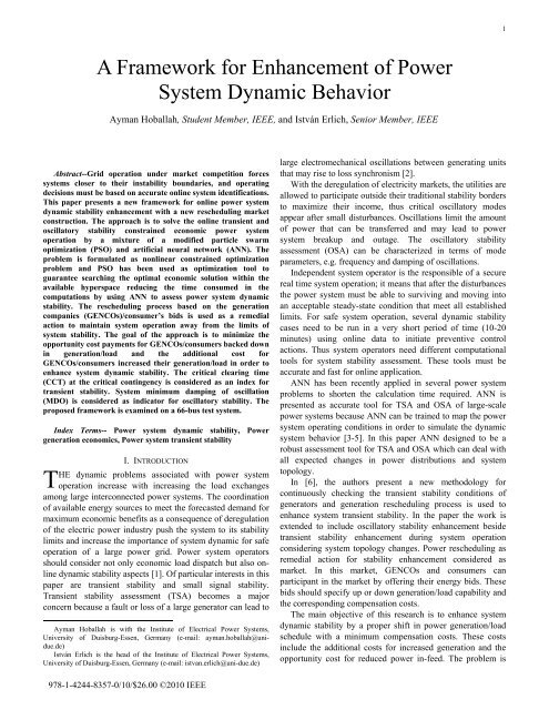
II. STUDY POWER SYSTEM<br />
The implementation <strong>of</strong> the proposed framework is<br />
illustrated through the <strong>Power</strong> Stability Test 16-machine<br />
network (PST16) [5]. The single line diagram <strong>of</strong> the test<br />
system is shown in Fig. 1. The test system contains 66-bus<br />
and is divided into three areas (A, B and C) connected through<br />
tie lines. It is developed based on characteristic parameters <strong>of</strong><br />
European power system to study different kinds <strong>of</strong> stability<br />
problems. The generators are considered hydropower and<br />
thermal power types and consist <strong>of</strong> number <strong>of</strong> blocks as<br />
shown in Fig. 1. The generator models are 5th order model<br />
with detailed exciter and governing systems.<br />
G1 G2 G3 G4 G5<br />
7x220 MVA 9x220 MVA 8x220 MVA 8x220 MVA 4x220 MVA<br />
G G G G G<br />
A4<br />
A1<br />
G<br />
G13<br />
7x247 MVA<br />
G G6<br />
4x247 MVA<br />
B4<br />
G10<br />
5x247 MVA<br />
G<br />
C8<br />
T3<br />
A7<br />
B9<br />
A2<br />
T9<br />
A5b<br />
B1<br />
C6<br />
A6<br />
G G12<br />
6x247 MVA<br />
T24<br />
C7<br />
C4<br />
C5<br />
AREA C<br />
C18<br />
T22<br />
G7 G8 G9<br />
6x259 MVA 6x259 MVA 8x259 MVA<br />
C17<br />
AREA A<br />
B6<br />
C11<br />
C14<br />
B2<br />
C12<br />
G16<br />
G 4x247 MVA<br />
G11<br />
5x259 MVA<br />
G G14<br />
5x 247 MVA<br />
G G15<br />
5x247 MVA<br />
15.75 kV<br />
110 kV<br />
220 kV<br />
380 kV<br />
G G G<br />
B7<br />
AREA B<br />
B14<br />
B13<br />
G<br />
B3<br />
Fig. 1. Single line diagram <strong>of</strong> the sixteen-machine, 66-bus test system<br />
Estimation <strong>of</strong> time varying dynamics using ANN introduce<br />
dependency on the data used in calibration that is not valid<br />
after change in system topology, <strong>for</strong> example, a line<br />
disconnection. To enhance the ability <strong>of</strong> ANN to deal with<br />
such situations, system topology and power distribution are<br />
considered to be changed during preparing Input/output<br />
patterns <strong>for</strong> ANN training. Table I lists the terminals <strong>of</strong> the<br />
disconnected transmission lines and Table II lists the name <strong>of</strong><br />
disconnected generators.<br />
TABLE I<br />
DISCONNECTED TRANSMISSION LINES DURING TOPOLOGY CHANGES<br />
Case<br />
Disconnected<br />
Transmission Line<br />
Terminals<br />
1<br />
Base<br />
case<br />
2<br />
A5b/A6<br />
3<br />
B13/B14<br />
4<br />
B13/ B14<br />
B4/ B9<br />
TABLE II<br />
DISCONNECTED GENERATORS DURING NETWORK CHANGES<br />
Case<br />
Disconnected<br />
Generators Name<br />
6<br />
G1-G2<br />
7<br />
G7-G8<br />
8<br />
G13<br />
III. GRID DYNAMIC BEHAVIOR EVALUATION<br />
5<br />
C4 / C7<br />
9<br />
G1-G2-G7-<br />
G8- G13<br />
A. Transient Stability Analysis<br />
The power system transient stability analysis leads to the<br />
solution <strong>of</strong> nonlinear systems set <strong>of</strong> differential algebraic<br />
equations. Time domain simulation (TDS) provides an<br />
accurate calculation by solving these equations through stepby-step<br />
integration by producing time response <strong>of</strong> all state<br />
variables. Transient stability is based on coherent behavior <strong>of</strong><br />
generators relative rotor angles procured from time domain<br />
simulation outputs. Under credible contingencies, if the<br />
relative angles enlarge gradually, after pre-defined accepted<br />
value generators no longer considered operated synchronously<br />
and , the system will lose its synchronism, otherwise it remain<br />
stable with a certain stability margin. The CCT is the<br />
maximum time duration that a fault may occur in power<br />
systems without failure in the system so as to recover to a<br />
steady state operation. CCT associated with each fault is a<br />
dynamic attribute <strong>for</strong> power systems which can be used as<br />
indicator <strong>for</strong> TSA. The time needed by relays to clear fault<br />
should be less than CCT to consider the system is transiently<br />
stable. Time domain simulations considering several<br />
contingencies at each operating point were carried out <strong>for</strong> the<br />
purpose <strong>of</strong> gathering CCT. The modeling and simulation<br />
results <strong>for</strong> load flow and corresponding CCT calculations<br />
were done by using the simulation package ‘<strong>Power</strong> <strong>System</strong><br />
<strong>Dynamic</strong>s (PSD)’ [7].<br />
B. Small Signal Stability Analysis<br />
Modal analysis <strong>of</strong> a set <strong>of</strong> differential equations is used to<br />
provide considerable insight into the stability properties <strong>of</strong> the<br />
system. In the investigation <strong>of</strong> OSA, the system equations are<br />
used to investigate the stability <strong>of</strong> the system by calculating<br />
the eigenvalues <strong>of</strong> the modified state matrix [8]. It requires<br />
data about complete system description, load flow analysis,<br />
linearization around current operating point, state space model<br />
<strong>for</strong>mulation, and then parameters estimation. Due to the time<br />
varying and strong nonlinear dynamics in large power<br />
systems, it requires significantly large computational ef<strong>for</strong>t.<br />
<strong>Dynamic</strong> behavior associated with major disturbances such<br />
as three phase short circuit is a good source <strong>of</strong> in<strong>for</strong>mation<br />
concerning system oscillations and the control system<br />
responses. The time responses <strong>of</strong> electrical signals are used to<br />
calculate the eigenvalues <strong>of</strong> the monitored system using<br />
2
ingdown analysis (Prony analysis) or normal operation<br />
analysis [9]. Prony analysis is a curve-fitting methodology that<br />
extends Fourier analysis by directly estimating the frequency,<br />
damping, strength, and relative phase <strong>of</strong> the modal<br />
components present in a recorded signal [10]. In this paper,<br />
Prony analysis is applied to the generators active power as<br />
signals that seem to be the most sensitive in use <strong>for</strong><br />
determination <strong>of</strong> mode parameters. From a systems view this<br />
choice is sensible in that an oscillation is due to a power<br />
imbalance at the swinging generators. <strong>Dynamic</strong> system<br />
identification toolbox (DSI) is used to identify system<br />
oscillation and damping during injected probing signals [11].<br />
In this paper, DSI is used to identify MDO to account the<br />
system response <strong>for</strong> change in fault location. In order to<br />
improve significantly the electromagnetic mode identification;<br />
a probing signal should be injected at certain location with a<br />
proper duration. In this paper three phase short circuit is<br />
applied at pre-selected fault location with different fault<br />
duration to investigate the system response. Fig. 2 shows the<br />
MDO calculated at different contingencies and fault durations.<br />
The calculated values likely remains constant with 1millisecond<br />
fault duration and thus the minimum damping at<br />
pre-selected fault location with 1-millisecond is considered as<br />
OSA during optimization process.<br />
Minimum damping<br />
<strong>of</strong> oscillation (p.u.)<br />
0.14<br />
0.12<br />
0.1<br />
0.08<br />
0.06<br />
0.04<br />
0.02<br />
0<br />
1-msec fault duration<br />
3-msec fault duration<br />
5-msec fault duration<br />
0 5 10 15 20 25 30<br />
Contingency number<br />
Fig. 2. MDO calculated from the time response<br />
Fig. 3 shows the time response <strong>of</strong> generators active power<br />
due to a single step fault at bus B6 in area B and Fig. 4<br />
presents the comparison between the real system data relative<br />
to the identified system data using DSI based Prony analysis<br />
toolbox. The observed inter-area oscillation mode with 0.87<br />
Hz and approximately 7.5% damping ratio is characterized.<br />
As seen in Fig. 3, Generators in area A oscillate in anti-phase<br />
with generators at area B and area C.<br />
Per unit change in generated<br />
active power<br />
x 10-3<br />
2<br />
G1<br />
G2<br />
G3<br />
1<br />
G4<br />
G5<br />
G6<br />
G7<br />
0<br />
G8<br />
G9<br />
G10<br />
G11<br />
-1<br />
G12<br />
G13<br />
G14<br />
G15<br />
-2<br />
2 4 6 8 10 12<br />
G16<br />
14<br />
Simulation time (sec)<br />
1.5<br />
0.5<br />
-0.5<br />
-1.5<br />
Fig. 3. Time response due to 1-millisecond short circuit at bus B6<br />
Real time system data relative to<br />
identified system using<br />
Prony analysis (p.u)<br />
x 10-4<br />
3<br />
2<br />
1<br />
0<br />
-1<br />
-2<br />
-3<br />
-4<br />
Real system data<br />
Identified system<br />
2 4 6 8 10 12 14 16 18<br />
Simulation time (sec)<br />
Fig. 4. Active power deviation relative to identified data using Prony analysis<br />
DSI is an efficient method <strong>for</strong> OSA but consumes time in<br />
input data preparation and additional cure required <strong>for</strong><br />
accurate estimate <strong>of</strong> system modes such as proper choice <strong>of</strong><br />
number <strong>of</strong> sample points and sampling ratio <strong>for</strong> proper signal<br />
to noise ratio [10]. Thus it is not suitable <strong>for</strong> on-line<br />
applications. Off-line trained ANN can be used to predict the<br />
MDO based on the current operating point as indicator <strong>for</strong><br />
OSA. Detection <strong>of</strong> low damping can then alarm operators or<br />
enables special protection schemes or adjust the rescheduling<br />
process to enhance system stability.<br />
C. ANN <strong>for</strong> TSA and OSA<br />
Two ANN are used in TSA and OSA. The generation <strong>of</strong><br />
input/output patterns <strong>for</strong> ANN training is achieved by<br />
randomly varying the loads in wide range in each expected<br />
system configuration. Optimal power flow is used to adapt the<br />
generation depending on the required power and produce the<br />
required system in<strong>for</strong>mation. At each operating point, TDS is<br />
used to calculate CCT and DSI is used to identify the MDO at<br />
pre-selected credible set <strong>of</strong> contingencies. The lowest values<br />
are selected as targets <strong>for</strong> ANN. Fig. 5 presents the block<br />
diagram <strong>of</strong> the main steps in ANN modeling process.<br />
Data Collection<br />
Features Generation Features Selection ANN Training<br />
Load Flow & TDS<br />
& Short Circuit<br />
Calculations<br />
Total collected patterns<br />
<strong>Power</strong> <strong>System</strong><br />
Changes in load level<br />
Changes in fault location<br />
Changes in system topology<br />
Calculated feature<br />
sets<br />
Initial<br />
feature<br />
set<br />
Fig. 5. Main steps in ANN modeling<br />
Reduced input<br />
patterns<br />
Features<br />
Selection<br />
Process<br />
Selected features<br />
Selected<br />
feature<br />
set<br />
A single neural network<br />
Network Models<br />
3<br />
<strong>Dynamic</strong><br />
Stability<br />
Indicator<br />
(CCT / MDO)<br />
Feature selection is necessary to reduce the large number <strong>of</strong><br />
available features in power system and select the most<br />
valuable in<strong>for</strong>mation contents that efficiently represent the
entire system. Initial feature sets are pre-selected based on<br />
engineering judgment be<strong>for</strong>e feature selection process. The<br />
initial feature sets include load flow in<strong>for</strong>mation such as bus<br />
voltages, generator powers, line flows, trans<strong>for</strong>mer powers,<br />
trans<strong>for</strong>mer tap sittings and demands. For dynamic stability<br />
assessment the ANN should be able to follow the changes in<br />
load levels, changes in power distribution, changes in system<br />
topology and ability <strong>for</strong> evaluating system dynamic behavior<br />
independent on fault location. In order to achieve this goal,<br />
Final features are selected in two stages as follows: First<br />
stage: Initial feature set is selected based on the knowledge <strong>of</strong><br />
the power system using power flow results, TDS and short<br />
circuit analysis. Second stage: In this stage, the input features<br />
are selected in three steps to improve the accuracy <strong>of</strong> ANN in<br />
TSA and OSA. First step: To characterize the severity <strong>of</strong><br />
faults to the generators and detect the fault location, the<br />
voltage drop at generator terminals immediately after a single<br />
step short circuit are preferred ANN inputs. As seen in Fig. 6,<br />
when a three phase fault occurs at bus A1 in area A <strong>of</strong> PST16<br />
the nearest generators get more response as indication <strong>of</strong> fault<br />
location.<br />
Per unit change in generators<br />
terminal voltage<br />
0.2<br />
G1<br />
G2<br />
0<br />
G3<br />
G4<br />
G5<br />
G6<br />
-0.2<br />
G7<br />
G8<br />
G9<br />
-0.4<br />
G10<br />
G11<br />
G12<br />
-0.6<br />
G13<br />
G14<br />
G15<br />
-0.8<br />
0 0.2 0.4 0.6 0.8 1 1.2<br />
G16<br />
1.4<br />
Simulation time (sec)<br />
Fig. 6. Voltage drops at generator terminals immediately after a single step<br />
short circuit at bus A1 in PST16 test system<br />
Second step: To characterize the change in power<br />
distribution due to change in the portion <strong>of</strong> areas in power<br />
generation, an Area <strong>Power</strong> Generation Distribution Factor<br />
(APGDF) <strong>for</strong> each area is used. This factor depends on the<br />
summation <strong>of</strong> generated energy in each area related to the<br />
summation <strong>of</strong> the total energy capacity <strong>of</strong> connected<br />
generators.<br />
N k<br />
∑ H i ⋅ P gi<br />
(1)<br />
APGDF = i = 1<br />
N k<br />
∑ H ⋅ S<br />
i = 1<br />
i<br />
where; H is the generator inertia constant, P active power in<br />
MW, S is generator capacity in MVA and Nk is the number <strong>of</strong><br />
generators in area k<br />
Third step: To characterize the varying in load levels and<br />
power flow through transmission lines during operating point<br />
adjustments, a systematic feature selection algorithm, in our<br />
case k-means clustering algorithm, is used to select the most<br />
gi<br />
important features from the initial selected sets <strong>of</strong> features.<br />
Selected features used to train the ANN <strong>for</strong> TSA and OSA<br />
are listed in Table III; these features reflect the system<br />
configuration, pre-contingency operating conditions, fault<br />
locations and severity <strong>of</strong> the disturbances.<br />
TABLE III<br />
FEATURES SELECTED FOR TSA AND OSA USING ANN<br />
Name <strong>of</strong> Features<br />
Terminal voltage drop<br />
Area power generation<br />
distribution factor<br />
Generator power<br />
Magnitude <strong>of</strong> bus<br />
voltage<br />
Trans<strong>for</strong>mer taps<br />
Tie-line power<br />
Loads power<br />
Selected Features <strong>for</strong> TSA & OSA<br />
ΔV <strong>of</strong> all generators after a fault<br />
APGDF <strong>for</strong> each Area<br />
Qg3 - Qg6 - Pg8 - Pg9 - Qg13 - Pg14<br />
VA4 - VA7 - VB7 - VC6 - VC8<br />
T24 - T22 - T9<br />
PA5b/B1 - PB6/C17 - QB6/C17<br />
PA2 -PA7 -PB3 -PC4 -PC7 -PC14 -<br />
QB1 -QB2 -QC12 -QC18<br />
A multilayer feed-<strong>for</strong>ward structure with the backpropagation<br />
training network is implemented to relate the<br />
selected input features and the corresponding CCT and MDO<br />
<strong>of</strong> the most critical contingency. The training algorithm used<br />
is the Levenberg-Marquardt algorithm. MATLAB neural<br />
network toolbox is used to implement ANN. All in<strong>for</strong>mation<br />
about trained ANN is saved to be used through the simulation<br />
process.<br />
IV. PROPOSED ALGORITHM<br />
A. Market Formulation<br />
The main target in the proposed algorithm is to investigate<br />
the energy market co-optimization based on extra cost<br />
payments minimization <strong>of</strong> energy under rescheduling process<br />
to enhance system dynamic stability considering system<br />
constraints. The proposed algorithm schematic diagram is<br />
shown in Fig. 7. As a responsibility <strong>of</strong> ISO in real time power<br />
system operation, system dynamic stability should be<br />
evaluated nearly at every 15 minutes. When the dynamic<br />
stability limits are violated, a counter measures are required to<br />
enhance the dynamic stability <strong>for</strong> a secure operation.<br />
In the paper, we suggest a new rescheduling market<br />
construction to reallocate the energy among suppliers and<br />
consumers who participate in the market by placing optional<br />
energy bids to enhance the power system dynamic stability.<br />
This market is a separate market established after the energy<br />
market clearance.<br />
In this market, all GENCOs and consumers have equal<br />
chance to participate with volunteer energy bids to increase or<br />
decrease their scheduled level (generation/load) based on<br />
energy market clearance. Based on the required cost <strong>for</strong><br />
control variables, the optimization starts with low cost control<br />
variables to minimize the required payments.<br />
4
Independent <strong>System</strong> Operator (ISO)<br />
Transmission <strong>System</strong> Operator (TSO)<br />
Yes<br />
<strong>Power</strong> Flow & Short<br />
Circuit Calculations<br />
<strong>Dynamic</strong> Stability<br />
No <strong>Power</strong> Flow & Short<br />
Circuit Calculations<br />
Input<br />
Input<br />
Features<br />
Features<br />
<strong>Power</strong><br />
Flow<br />
OSA TSA<br />
OSA TSA<br />
Results<br />
Minimum<br />
Damping<br />
CCT<br />
Minimum<br />
Damping<br />
CCT<br />
Fitness &<br />
Constraints<br />
Calculations<br />
Suggestion <strong>for</strong><br />
Counter Measures<br />
Optimization<br />
15 Minute<br />
Stop<br />
Optimal<br />
Counter<br />
Measures<br />
Counter Measures<br />
Yes No<br />
Optimum Solution<br />
Fig. 7. The schematic diagram <strong>of</strong> the proposed approach<br />
In the market, a participant whose energy is backed down<br />
should be paid an opportunity cost <strong>for</strong> reduction in power<br />
generation/load level. On the other hand, a participant whose<br />
energy is increased will be paid the cost <strong>of</strong> increase in<br />
generation/load level based on market clearing price (MCP)<br />
and may be additional costs required to execute the required<br />
change. The GENCOs and consumers are not participate in<br />
the market will be treated financially based on energy market<br />
clearance. Cash flow block diagram according to the new<br />
rescheduling process is shown in Fig. 8.<br />
AI Energy Market Clearance<br />
(Financial Rules)<br />
AII<br />
Consumers I (COI)<br />
( More in consumption )<br />
Consumers II (COII)<br />
( Less in consumption )<br />
Consumers III (COIII)<br />
(No change in consumption)<br />
BI BII<br />
CI<br />
Transimission <strong>System</strong><br />
Operator (TSO)<br />
& Independent <strong>System</strong><br />
Operator (ISO)<br />
CII<br />
GENCOs I<br />
( More in generation )<br />
GENCOs II<br />
( Less in generation )<br />
GENCOs III<br />
( No change in generation )<br />
AI, AII: Money flow based energy market clearance <strong>for</strong> energy supply.<br />
BI, BII: Additional money flow due to more in generation/consumption.<br />
CI, CII: Opportunity cost <strong>for</strong> less in generation<br />
Fig. 8. Money flow to enhance transient stability using generation<br />
rescheduling<br />
Based on energy market clearance, market cleared to<br />
specify power schedule and corresponding money flow from<br />
consumers to GENCOs (money flow AI and AII). The new<br />
rescheduling process will shift part <strong>of</strong> generated power from<br />
GENCOs I to GENCOs II and may be change in energy<br />
consumption <strong>of</strong> consumers I and consumers II in order to<br />
enhance dynamic stability. Additional costs are paid to<br />
GENCOs I and consumers I to increase in scheduled<br />
generation/load level. In the same time, opportunity costs will<br />
be paied to GENCOs II and consumers II <strong>for</strong> less in<br />
generation/load level.<br />
B. Problem Formulation<br />
The participants in the market submit their volunteer<br />
energy bids including limits <strong>of</strong> change and the corresponding<br />
cost functions. These <strong>of</strong>fered biddings can be implemented<br />
with any acceptable <strong>for</strong>m such as linear bid strategy as shown<br />
in Fig. 9. Multi-stage linear biding is <strong>of</strong>fered <strong>for</strong> opportunity<br />
cost required <strong>for</strong> a reduction in generation with the limits<br />
− −<br />
( Δ P , min ΔP ) and additional cost beside market clearing<br />
max<br />
price <strong>for</strong> increase in generation more than the dispatched<br />
+ +<br />
power within limits ( Δ P , min Δ P ). min<br />
ΔP − gi<br />
−<br />
Δ P max<br />
Cost (€ / MWh)<br />
Opportunity cost <strong>for</strong> Additional cost <strong>for</strong> increase<br />
reduction in generation in generation above MCP<br />
−<br />
+<br />
Δ P min Δ P min<br />
<strong>Power</strong> Change in (MW)<br />
Fig. 9. Opportunity and additional costs <strong>for</strong> generation changes<br />
+<br />
Δ P max<br />
5<br />
ΔP + gi<br />
The problem is <strong>for</strong>mulated as cost minimization objective<br />
function. The target is to minimize the costs associated with<br />
power rescheduling to obtain feasible power system operating<br />
point with an acceptable dynamic stability level. The required<br />
transient stability level and the acceptable MDO are taken into<br />
consideration as constraints. The objective function based on<br />
opportunity and additional costs can be mathematically<br />
<strong>for</strong>mulated as [6]:<br />
Minimize:<br />
N d1 ⎛ ⎞<br />
N d2 ⎛ ⎞<br />
Costs = ∑ f ⎜ ΔP<br />
+<br />
⎟ + ∑ f ⎜ ΔP<br />
−<br />
⎟ (2)<br />
i<br />
= ⎝ gi ⎠<br />
j<br />
= ⎝ gj<br />
i 1<br />
j 1<br />
⎠<br />
Subject to:<br />
<strong>Power</strong> flow constraints<br />
h(x) = 0<br />
(3)<br />
g (x) = 0<br />
(4)<br />
Transient stability constraint<br />
CCT ≥ CCT<br />
(5)<br />
min<br />
ξ ≥ ξ<br />
(6)<br />
min<br />
where f is the cost function based on bidding strategies <strong>of</strong><br />
participants in rescheduling process, ΔP is the change in<br />
scheduled power from initial operating point based on market<br />
clearance, Nd1 and Nd2 are the number <strong>of</strong> participants whose<br />
energy is increased and decreased respectively, h represents
power balance equations at all nodes, g represents voltage and<br />
current limitations within the grid, x is the vector <strong>of</strong> control<br />
variables including trans<strong>for</strong>mer taps, load variations and<br />
generated active and reactive power. The CCTmin is the<br />
acceptable minimum CCT limit. ξ is the system damping<br />
and ξ is the minimum acceptable system damping.<br />
min<br />
V. COUNTER MEASURES AND OPTIMIZATION PROCESS<br />
PSO is a population based optimization technique was<br />
introduced by Kennedy and Eberhard in 1995 to simulate the<br />
bird flock and is used to solve many optimization problems<br />
[12]. PSO is used as optimization tool to obtain the optimal<br />
counter measures to enhance system dynamic stability with<br />
minimum cost. During the optimization process, the particles<br />
move through hyperspace defined by the limits <strong>of</strong> the control<br />
variables and updated to satisfy all constraints. Constraints<br />
handling method is a highly important. In [6] a self adaptive<br />
penalty function based algorithm <strong>for</strong> constrained optimization<br />
in implemented to achieve this target and is used in this paper.<br />
The ISO has to check the dynamic stability each 15<br />
minutes; if system is stable, energy schedule from energy<br />
market directed to real time application else optimization start<br />
to search about proper remedial actions. Participant’s bids<br />
should be submitted and objective function <strong>for</strong>mulated. The<br />
population in PSO is initiated with a dimensional vector x,<br />
where x is the vector <strong>of</strong> control variables including change in<br />
rescheduled active and reactive power (Δq, Δp) <strong>of</strong> all<br />
participants in the market in addition to all online available<br />
control variables such as trans<strong>for</strong>mer tap settings (Δt) and<br />
FACTS devices to control the injected reactive power.<br />
T<br />
T T T<br />
x = [ Δ p Δ q Δ t ]<br />
Δ p = [ Δ p , Δ p , L , Δ p<br />
1<br />
1<br />
1<br />
Δ t = [ Δ t , Δ t , L , Δ t<br />
2<br />
2<br />
2<br />
Nt<br />
Np1<br />
Δ q = [ Δ q , Δ q , L , Δ q<br />
where Np1 and Np2 are the number <strong>of</strong> participants in active<br />
and reactive power rescheduling, Nt is the number <strong>of</strong><br />
trans<strong>for</strong>mer taps.<br />
For each particle in the population, the load flow is used to<br />
adjust the operating point and the power system subjected to a<br />
set <strong>of</strong> selected critical contingencies as described be<strong>for</strong>e.<br />
Based on the selected features, <strong>of</strong>fline trained ANNs are used<br />
to estimate CCT and minimum damping <strong>of</strong> system<br />
oscillations. After ranking, when the minimum CCT and/or<br />
damping ratio are less than the desired values, it considered as<br />
constraints violation during optimization. Thus the<br />
constrained objective function is <strong>for</strong>mulated and velocities<br />
and positions <strong>of</strong> particles are updated. The optimization<br />
process continued until reach the stopping criteria in the<br />
direction to enhance the system dynamic stability with<br />
minimum cost. The final solution should make all potentially<br />
critical contingencies completely stable at the same time. The<br />
used code <strong>for</strong> PSO was implemented by MATLAB s<strong>of</strong>tware.<br />
Np2<br />
]<br />
]<br />
]<br />
(7)<br />
VI. NUMERICAL RESULTS<br />
A. Per<strong>for</strong>mance Evaluation <strong>of</strong> ANN in TSA and OSA<br />
The ability <strong>of</strong> ANN <strong>for</strong> TSA considering system topology<br />
changes and change in power distributions is presented in [4].<br />
Fig. 10 presents randomly selected three operating points <strong>for</strong><br />
each case study presented in Table I, II during testing with<br />
un<strong>for</strong>eseen set <strong>of</strong> input/output pattern.<br />
CCT (sec)<br />
0.5<br />
0.4<br />
0.3<br />
0.2<br />
0.1<br />
0<br />
CCT using ANN at different operating points<br />
CCT using TDS at different operating points<br />
1 2 3 4 5<br />
Cases<br />
6 7 8 9<br />
Fig. 10. CCT estimated by ANN as indicator <strong>for</strong> TSA relative to CCT<br />
calculated by TDS<br />
The same procedure described in [4] is used to model ANN<br />
<strong>for</strong> OSA. A single hidden layer feed-<strong>for</strong>ward structure ANN<br />
trained using beck-propagation is used <strong>for</strong> OSA. ANN is used<br />
to map the relation between the selected features listed in<br />
Table III and the MDO calculated by DSI at each operating<br />
point as described in section III. The number <strong>of</strong> neurons in<br />
input layer is equal to the number <strong>of</strong> selected features. The<br />
output layer contains one neuron related to the target OSA.<br />
The number <strong>of</strong> neurons in the hidden layer is selected to<br />
minimize the root mean square error (RMSE) between the<br />
estimated damping ratio by ANN and the target damping ratio<br />
estimated by DSI. Fig. 11 shows the target percentage<br />
damping ratio relative to estimated values at randomly<br />
selected 50 un<strong>for</strong>eseen operating points to test the ability <strong>of</strong><br />
ANN in OSA.<br />
Damping <strong>of</strong> oscillations (%)<br />
8<br />
6<br />
4<br />
2<br />
0<br />
Estimated MDO using ANN<br />
Target MDO using DSI<br />
-2<br />
0 5 10 15 20 25 30 35 40 45 50<br />
The number <strong>of</strong> pattern<br />
Fig. 11. The percentage minimum damping estimated by ANN relative to<br />
target minimum damping calculated by DSI<br />
Fig. 12 shows a randomly selected three operating point <strong>for</strong><br />
each case in Table I, II.<br />
6
Damping <strong>of</strong> oscillations (p.u.)<br />
0.25<br />
0.2<br />
0.15<br />
0.1<br />
0.05<br />
0<br />
CCT using ANN at different operating points<br />
CCT using TDS at different operating points<br />
1 2 3 4 5<br />
Cases<br />
6 7 8 9<br />
Fig. 12. Min. damping estimated by ANN as indicator <strong>for</strong> TSA relative to<br />
estimated values by DSI<br />
The ANN per<strong>for</strong>mances are evaluated using average<br />
estimation error (AE), standard deviation (σ) and mean<br />
absolute percentage error (MAPE) between estimated<br />
minimum damping using trained ANN and target value<br />
estimated by DSI. The definitions are given as follow:<br />
1<br />
N<br />
y − y~<br />
N d<br />
( y y~ )<br />
RMSE = ∑ −<br />
(8)<br />
E<br />
k<br />
k = 1<br />
d<br />
k<br />
k<br />
k k = ( )<br />
(9)<br />
y<br />
k<br />
N d<br />
∑<br />
d k = 1<br />
1<br />
AE = E<br />
(10)<br />
k<br />
N<br />
1<br />
N<br />
Nd<br />
( E AE)<br />
2<br />
k = 1<br />
d<br />
k<br />
MAPE =<br />
1<br />
N<br />
N d<br />
∑ E k<br />
k = 1<br />
(12)<br />
σ = ∑ −<br />
(11)<br />
d<br />
where y is the calculated CCT by TDS; ỹ is the estimated CCT<br />
using ANN; Nd is the number <strong>of</strong> input patterns.<br />
The results provide the suitability <strong>of</strong> ANN in TSA and<br />
OSA with a reasonable degree <strong>of</strong> accuracy. Table IV<br />
summarize the per<strong>for</strong>mance evaluations <strong>of</strong> ANN in TSA and<br />
OSA<br />
TSA using ANN<br />
OSA using ANN<br />
TABLE IV<br />
PERFORMANCE OF ANN IN TSA AND OSA<br />
AE (%)<br />
-0.1343<br />
-0.3520<br />
2<br />
σ (%)<br />
7.088<br />
6.400<br />
MAPE (%)<br />
3.467<br />
4.520<br />
B. Application <strong>of</strong> the Proposed Approach<br />
The implementation <strong>of</strong> the proposed approach is illustrated<br />
through the PST16 presented in section II. A highly stressed<br />
operating point is selected to investigate the suitability <strong>of</strong> the<br />
proposed framework in dynamic stability enhancement. The<br />
uni<strong>for</strong>m market clearing price, in which all suppliers are paid<br />
the same price without considering dynamic stability into<br />
account, is considered as an initial schedule. In this operating<br />
point, the CCT if found to be 82.5 millisecond with a three<br />
phase fault at bus A2 in area A and the corresponding<br />
minimum damping <strong>of</strong> oscillation is 1%. The target <strong>for</strong> a<br />
dynamic stable system operation is assumed to be 150<br />
milliseconds as a common <strong>for</strong> all circuit-breakers in the<br />
system and the acceptable sufficient MDO is 4%. To enhance<br />
the system dynamic stability, a new market implemented and<br />
GENCOs and consumers are asked to submit their energy<br />
bids. All GENCOs are assumed provide the reactive power<br />
service to support the grid voltage without additional costs<br />
and participate in the market.<br />
The opportunity and additional cost coefficients and power<br />
generation limits are presented in Table V The minimum up<br />
and down acceptable change in generations are assumed to be<br />
20 MW <strong>for</strong> all generators and the maximum change is<br />
governed by generation limits <strong>for</strong> each generator. The system<br />
has 60 control variables; these variables contain 16 active<br />
generated power and no cost variables including 16 reactive<br />
generated powers and 28 trans<strong>for</strong>mers-tap settings. The step<br />
size <strong>for</strong> adjusting trans<strong>for</strong>mers-tap setting is 0.005 per unit <strong>for</strong><br />
their adjustable voltage range between 0.90 and 1.10 per unit.<br />
TABLE V<br />
GENERATORS CAPACITY AND COST COEFFICIENT FOR 16-MACHINES SYSTEM<br />
Generator<br />
name<br />
G1<br />
G2<br />
G3<br />
G4<br />
G5<br />
G6<br />
G7<br />
G8<br />
G9<br />
G10<br />
G11<br />
G12<br />
G13<br />
G14<br />
G15<br />
G16<br />
Pgmax<br />
MW<br />
1500<br />
1500<br />
1650<br />
1650<br />
600<br />
700<br />
1500<br />
1500<br />
2000<br />
1150<br />
1250<br />
1650<br />
1450<br />
1250<br />
1200<br />
950<br />
Pgmin<br />
MW<br />
300<br />
300<br />
450<br />
450<br />
150<br />
150<br />
300<br />
300<br />
300<br />
350<br />
250<br />
400<br />
400<br />
150<br />
250<br />
250<br />
α u<br />
€/MWh<br />
0.124<br />
0.116<br />
0.136<br />
0.132<br />
0.125<br />
0.17<br />
0.121<br />
0.144<br />
0.152<br />
0.146<br />
0.158<br />
0.162<br />
0.164<br />
0.128<br />
0.156<br />
0.12<br />
βu €/MWh2 βu €/MWh2 6<br />
5<br />
4.5<br />
8<br />
9<br />
7<br />
6<br />
4<br />
5<br />
8<br />
5.8<br />
2.6<br />
6.4<br />
6.28<br />
6.56<br />
5<br />
α d<br />
€/MWh<br />
0.102<br />
0.0913<br />
0.13<br />
0.114<br />
0.114<br />
0.184<br />
0.1922<br />
0.196<br />
0.121<br />
0.15<br />
0.125<br />
0.118<br />
0.109<br />
0.19<br />
0.1134<br />
0.108<br />
βd €/MWh2 βd €/MWh2 2<br />
1<br />
3.5<br />
2<br />
5.9<br />
4<br />
3<br />
5<br />
3<br />
2<br />
2.8<br />
3.6<br />
3.4<br />
3.28<br />
5.56<br />
2.5<br />
Table VI and Table VII present the value <strong>of</strong> trans<strong>for</strong>mers<br />
tap settings and active power generation be<strong>for</strong>e and after<br />
rescheduling process using PSO respectively. According to<br />
the results after rescheduling process, there are three<br />
generators will not participate in rescheduling process to<br />
satisfy the required minimum limit <strong>of</strong> change. During the<br />
simulation, the required dynamic stability limits are<br />
considered as constraints beside all system limits. After<br />
rescheduling, the dynamic stability enhanced and the required<br />
limits are satisfied. The total opportunity and additional costs<br />
required to be paid to participants in the market is 18733.12<br />
7
€/h. the new CCT is 165.5 milliseconds with 4.63% MDO.<br />
TABLE VI<br />
PER UNIT TRANSFORMERS-TAP CONTROL VARIABLES<br />
Trans<strong>for</strong>mer<br />
name<br />
T1<br />
T2<br />
T3<br />
T4<br />
T5<br />
T6<br />
T7<br />
T8<br />
T9<br />
T10<br />
T11<br />
T12<br />
T13<br />
T14<br />
Taps be<strong>for</strong>e<br />
rescheduling<br />
1.025<br />
1.000<br />
1.025<br />
1.050<br />
1.030<br />
0.950<br />
0.995<br />
0.985<br />
0.955<br />
1.015<br />
1.020<br />
1.020<br />
1.025<br />
1.020<br />
Taps after<br />
rescheduling<br />
0.960<br />
0.950<br />
1.025<br />
1.025<br />
1.000<br />
1.025<br />
1.000<br />
1.020<br />
1.005<br />
1.030<br />
1.020<br />
1.020<br />
1.005<br />
1.020<br />
Trans<strong>for</strong>mer Taps be<strong>for</strong>e<br />
name rescheduling<br />
T15<br />
T16<br />
T17<br />
T18<br />
T19<br />
T20<br />
T21<br />
T22<br />
T23<br />
T24<br />
T25<br />
T26<br />
T27<br />
T28<br />
1.005<br />
0.995<br />
0.975<br />
1.025<br />
0.985<br />
1.025<br />
1.005<br />
1.030<br />
1.020<br />
1.050<br />
1.025<br />
1.025<br />
1.050<br />
1.025<br />
Taps after<br />
rescheduling<br />
1.002<br />
1.025<br />
1.00<br />
1.025<br />
1.025<br />
1.000<br />
1.005<br />
1.030<br />
1.020<br />
1.025<br />
0.975<br />
1.000<br />
0.970<br />
1.050<br />
TABLE VII<br />
POWER GENERATION (MW) BEFORE AND AFTER RESCHEDULING PROCESS<br />
Generator<br />
name<br />
Generation be<strong>for</strong>e<br />
rescheduling<br />
Generation after<br />
rescheduling<br />
Generation<br />
change<br />
Opportunity<br />
costs (€/h)<br />
G1 1108.984 1176.4 67.415 834.729<br />
G2 1083.778 1060.3 -23.478 -31.399<br />
G3 1143.438 1020.5 -122.938 2697.347<br />
G4 1001.055 1121.055 120 1545.6<br />
G5 600.000 515.4 -84.6 1315.052<br />
G6 700.000 650.8 -49.2 642.197<br />
G7 972.104 1105.1 132.992 3681.074<br />
G8 1044.719 1127.3 82.580 1312.386<br />
G9 1276.600 1399.7 123.1 2918.887<br />
G10 915.240 915.24 0.00 0.00<br />
G11 984.210 984.21 0.00 0.00<br />
G12 982.150 1018.8 36.651 312.912<br />
G13 969.570 1032.5 62.932 1090.063<br />
G14 1000.000 1000.00 0.00 0.00<br />
G15 994.400 1082.3 87.900 1556.942<br />
G16 1118.770 1002.6 -116.170 1748.098<br />
VII. CONCLUSION<br />
A new framework <strong>for</strong> enhancement <strong>of</strong> power system<br />
dynamic stability based on PSO-ANN is developed and tested<br />
in this paper. A new market <strong>for</strong> active power rescheduling is<br />
implemented to enhance system dynamic stability. In the<br />
market, participants introduce their <strong>of</strong>fers and PSO-ANN is<br />
used as optimization tool to find a solution to enhance online<br />
dynamic stability with minimum payments <strong>for</strong> participants in<br />
the market. ANN is implemented as a robust tool <strong>for</strong> TSA and<br />
OSA reducing the time consumed during repeatedly<br />
calculations <strong>of</strong> TSA and OSA. ANN is a very fast tool <strong>for</strong><br />
TSA and OSA estimations compared to traditional methods<br />
but should be trained carefully over a wide hyperspace in<br />
order to achieve high accuracy <strong>of</strong> estimation. The ANN is<br />
trained once <strong>for</strong> a given power system <strong>for</strong> any expected<br />
situation and then used <strong>for</strong> any load condition in the system.<br />
The results emphasize PSO capability <strong>of</strong> handling nonlinear<br />
mixed-integer optimization problems with complex objective<br />
function and constraints such as rescheduling process <strong>for</strong><br />
dynamic stability enhancement. The results show that the new<br />
framework can be applied in the real time power system<br />
operation to adjust system operating point <strong>for</strong> system dynamic<br />
stability enhancement with minimum cost during a<br />
rescheduling process.<br />
[1]<br />
VIII. REFERENCES<br />
H. R. Cai, C. Y. Chung and K. P. Wong, "Application <strong>of</strong> Differential<br />
Evolution Algorithm <strong>for</strong> Transient Stability Constrained Optimal<br />
<strong>Power</strong> Flow," IEEE Trans. on <strong>Power</strong> <strong>System</strong>s, vol. 23, no. 2, pp. 719–<br />
728, May. 2008.<br />
[2] J. F. Hauer, F. J. Hughes, D. Trudnowski, G. Rogers, J. Pierre, L.<br />
Scharf and W. Litzenberger, "A <strong>Dynamic</strong> In<strong>for</strong>mation Manager <strong>for</strong><br />
Networked Monitoring <strong>of</strong> Large <strong>Power</strong> <strong>System</strong>s," Tech. Rep. WO<br />
8813-01, EPRI. 42, 1998.<br />
[3] Yakout Mansour, Ebrahim Vaahedi and M. El-Sharkawi, "<strong>Dynamic</strong><br />
Security Contingency Screening and Ranking using Neural<br />
[4]<br />
Networks", IEEE Trans. on Neural Networks, Vol. 8, No. 4, pp. 942-<br />
950, May 1997.<br />
A. Hoballah and I. Erlich, "Transient Stability Assessment using<br />
ANN Considering <strong>Power</strong> <strong>System</strong> Topology Changes," ISAP 2009,<br />
<strong>Power</strong> & Energy Society, November 2009, Curitiba, Brazil<br />
[5] Simon P. Teeuwsen, Istvan Erlich and Mohamed A. El-Sharkawi,<br />
"Neural Network based Classification Method <strong>for</strong> Small Signal<br />
Stability Assessment," IEEE <strong>Power</strong>Tech, Bologen, Italy, June, 2003.<br />
[6] A. Hoballah and I. Erlich, "PSO-ANN approach <strong>for</strong> transient stability<br />
constrained economic power generation," <strong>Power</strong>Tech2009 IEEE<br />
Bucharest, pp. 1 – 6, July 2009<br />
[7] István Erlich, "Analysis and simulation <strong>of</strong> dynamic behavior <strong>of</strong> power<br />
system," Postdoctoral lecture qualification, Dept. <strong>of</strong> electrical<br />
engineering, Dresden University, Germany, 1995.<br />
[8] I. Erlich and A. Fischer, "Fast Assessment <strong>of</strong> Small-Signal Osillatory<br />
Stability in Large Interconnected <strong>Power</strong> <strong>System</strong>s," Balkan <strong>Power</strong><br />
Conference BPC, June 2002 Belgrade, Yugoslavia.<br />
[9] J. Hauer, C. Demeure, and L. Scharf‚ "Initial results in Prony analysis<br />
<strong>of</strong> power system response signals," IEEE Transactions on <strong>Power</strong><br />
<strong>System</strong>s, vol. 5, no. 1, 1990<br />
[10] J. Hauer, "Application <strong>of</strong> Prony analysis to the determination <strong>of</strong><br />
modal content and equivalent models <strong>for</strong> measured power system<br />
response," IEEE Trans. <strong>Power</strong> <strong>System</strong>., 1991, 6, (3), pp. 1062–1068.<br />
[11] Available: www.naspi.org/resources/archive/archiveresources.stm<br />
[12] J. Kennedy and R. C. Eberhart, “Particle Swarm Optimization,” Proc.<br />
IEEE International Conference on Neural Networks, 1995, IEEE<br />
Service Center Piscataway, NJ, pp. IV: pp. 1942–1948, Aug. 2004.<br />
[1]<br />
IX. BIOGRAPHIES<br />
Ayman Hoballah received the B.Sc. and M.Sc. degrees<br />
in electrical engineering from the Tanta University, Egypt<br />
in 1996 and 2003. Since 1998, he has been with the<br />
Electrical <strong>Power</strong> Department, Faculty <strong>of</strong> Engineering,<br />
University <strong>of</strong> Tanta/Egypt. He started his Ph.D. in the<br />
university Duisburg- Essen, Germany in 2007 supported<br />
by an Egyptian government scholarship. His Ph.D. thesis<br />
focuses on the power system transient stability.<br />
István Erlich (1953) received his Dipl. Ing. degree in<br />
electrical engineering from the University <strong>of</strong><br />
Dresden/Germany in 1976. After his studies, he worked<br />
in Hungary in the field <strong>of</strong> electrical distribution networks.<br />
From 1979 to 1991, he joined the Department <strong>of</strong><br />
Electrical <strong>Power</strong> <strong>System</strong>s <strong>of</strong> the University <strong>of</strong> Dresden<br />
again, where he received his PhD degree in 1983. In the<br />
period <strong>of</strong> 1991 to 1998, he worked with the consulting<br />
company EAB in Berlin and the Fraunh<strong>of</strong>er Institute IITB Dresden<br />
respectively. During this time, he also had a teaching assignment at the<br />
University <strong>of</strong> Dresden. Since 1998, he is Pr<strong>of</strong>essor and head <strong>of</strong> the Institute <strong>of</strong><br />
Electrical <strong>Power</strong> <strong>System</strong>s at the University <strong>of</strong> Duisburg-Essen/Germany. His<br />
major scientific interest is focused on power system stability and control,<br />
modeling and simulation <strong>of</strong> power system dynamics including intelligent<br />
system applications. He is a member <strong>of</strong> VDE and senior member <strong>of</strong> IEEE.<br />
8