high power system (2510kb) - TAIYO
high power system (2510kb) - TAIYO
high power system (2510kb) - TAIYO

You also want an ePaper? Increase the reach of your titles
YUMPU automatically turns print PDFs into web optimized ePapers that Google loves.
33<br />
TPH<br />
SELECTION MATERIALS<br />
■ SELECTION OF TYPE FOR THIN TYPE PIERCING WORK<br />
For selecting a toggle press, the following are necessary.<br />
1. Force necessary for work. (Working force) 2. Two items<br />
of working stroke shall be defined to check up with the<br />
output characteristics of toggle press.<br />
As working stroke is composed of work plate thickness<br />
and crotch as shown in chart, formula q is given.<br />
R = t +R′ . . . q<br />
R: Working stroke<br />
t : Work plate thickness<br />
R′ : Crotch (Crotch of punch against die)<br />
For force necessary for thin plate piercing work (working<br />
force), formula w, e are given according to the product<br />
of shearing stress and area.<br />
F =Rt . . . w For round hole:<br />
F : Shearing load (N) F = π Dt . . . e<br />
R: Length of shearing latus (mm) D : Round hole diameter<br />
t : Plate thickness (mm)<br />
: Shearing stress (N/mm 2 )<br />
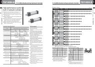
The characteristics of toggle press output and displacement<br />
(F–R) shown in chart indicates the output of 90%<br />
(P = 0.5MPa) and 75% (P = 0.7MPa) against the actual<br />
output to mitigate the shocking force in the thin plate<br />
piercing work. For the same reason, the load range is<br />
restricted to the section at 4mm from full stroke point.<br />
¡EXAMPLE OF WORKING CONDITIONS<br />
Round hole piercing work D = 15 t = 0.8<br />
{<br />
= 294N/mm 2<br />
Selection procedures (refer to Fig. 1)<br />
1. Against shearing force 294N/mm2 2. Calculate point A corresponding to plate thickness t =<br />
0.8 and hole bore D = 15.<br />
3. Line is drawn at right above point A and is extended<br />
to toggle press characteristics chart.<br />
4. Read the respective conditionsRfrom the cross point<br />
of 3 lines and characteristics curve.<br />
{<br />
a B . . . TPH-015040 P = 0.5MPa B = 2.4mm<br />
b C . . . TPH-020040 P = 0.5MPa C = 4.0mm<br />
c E . . . TPH-015040 P = 0.7MPa E = 2.9mm<br />
Calculate the maximum crotch according to type and<br />
operating pressure as theRdimension corresponding to<br />
B, C, E is equivalent toRof formula q.<br />
SHEARING STRESS OF MATERIALS N/mm 2<br />
Materials<br />
Lead<br />
Tin<br />
Aluminum<br />
Aluminum alloy<br />
Duralumin<br />
Phosphor bronze<br />
Nickel silver<br />
Nickel plate<br />
Shearing stress<br />
Hard<br />
–<br />
–<br />
127~157<br />
127~177<br />
373<br />
–<br />
441~549<br />
–<br />
Soft<br />
19.6~29.4<br />
29.4~39.2<br />
68.6~88.3<br />
68.6~108<br />
216<br />
490<br />
275~353<br />
245<br />
Materials<br />
Zinc<br />
Copper<br />
Brass<br />
Rolled bronze<br />
Mild steel plate<br />
lron plate for deep crest<br />
Steel plate<br />
Stainless steel plate<br />
PNEUMATIC TOGGLE PRESS<br />
Punch<br />
Work<br />
Crotch<br />
R<br />
a R– t = 2.4 – 0.8 = 1.6(mm)<br />
R’<br />
b R– t = 4.0 – 0.8 = 3.2 (mm)<br />
Die<br />
c R– t = 2.9 – 0.8 = 2.1 (mm)<br />
Decide on the type with crotch taken in consideration.<br />
“Application limit” in chart D–t (Fig. 1) indicates the limit<br />
of process available plate thickness-hole bore with toggle<br />
press output taken in consideration at the minimum<br />
crotch of 1mm.<br />
WORK SHEARING STRESS 294N/mm 2<br />
R(mm)<br />
t (mm)<br />
6<br />
4<br />
2<br />
0<br />
D (mm)<br />
0.5<br />
1.0<br />
1.5<br />
1.5<br />
2.0<br />
2.5<br />
3.0<br />
For 1 ton<br />
C<br />
1000<br />
4.9<br />
B<br />
TP 020040<br />
TP 015040<br />
P=0.5MPa<br />
P=0.7MPa<br />
E For<br />
1.5tons For 2 tons<br />
14.7<br />
F(kN)<br />
19.6<br />
10 20 30 40<br />
A<br />
(t=0.8. D=f15)<br />
Limit of D-t relation<br />
¡“LIMIT OF D – t RELATION”<br />
The limit calculated from the minimum hole bore against<br />
plate thickness is indicated as reference since the process<br />
available hole bore (minimum bore) against optional<br />
plate thickness is limited for general piercing work.<br />
¡PIERCING WORK OTHER THAN ROUND HOLE<br />
In the case of (long hole, square) other than round hole,<br />
the working force calculated from formula w is computed<br />
in output–displacement (F–R) characteristic lateral<br />
shaft (F) in Fig. 1, and crotch is confirmed according<br />
to the same method as that for round hole to decide<br />
on the type.<br />
Shearing stress<br />
Soft Hard<br />
118<br />
177~216<br />
216~294<br />
314~392<br />
314<br />
294~343<br />
441~490<br />
510<br />
196<br />
245~294<br />
343~392<br />
392~588<br />
392<br />
–<br />
539~588<br />
549<br />
Materials<br />
Steel 0.1%C 245<br />
0.2%C 314<br />
0.3%C 353<br />
0.4%C 441<br />
0.6%C 549<br />
0.8%C 706<br />
1.0%C<br />
785<br />
Silicon steel plate 441<br />
Permaroy 510<br />
D<br />
Application limit<br />
P=0.7MPa<br />
Application limit<br />
P=0.5MPa<br />
t<br />
Fig. 1<br />
(Work thickness)<br />
(Crotch)<br />
Shearing stress<br />
Soft Hard<br />
314<br />
392<br />
471<br />
549<br />
706<br />
883<br />
1030<br />
549<br />
–