high power system (2510kb) - TAIYO
high power system (2510kb) - TAIYO
high power system (2510kb) - TAIYO

You also want an ePaper? Increase the reach of your titles
YUMPU automatically turns print PDFs into web optimized ePapers that Google loves.
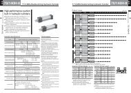
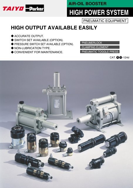
ACCURATE OUTPUT.<br />
SWITCH SET AVAILABLE (OPTION).<br />
PRESSURE SWITCH SET AVAILABLE (OPTION).<br />
NON-LUBRICATION TYPE.<br />
CONVENIENT FOR MAINTENANCE.<br />
AIR-OIL BOOSTER<br />
HIGH OUTPUT AVAILABLE EASILY<br />
HIGH POWER SYSTEM<br />
PNEUMATIC EQUIPMENT<br />
PNEUMERLOCK<br />
CLAMPING ELEMENT<br />
PNEUMATIC TOGGLE PRESS<br />
CAT. -124d
CONTENTS<br />
PNEUMERLOCK<br />
FEATURES ...................................................................................................... PAGE 2<br />
COMBINATION OF BOOSTER .................................................................................PAGE 3<br />
TYPE OUTLINE · CODE ........................................................................................PAGE 4<br />
DIRECT PRESSURE TYPE BOOSTER<br />
SPECIFICATIONS ...............................................................................................PAGE 5<br />
SECTIONAL DRAWINGS ...................................................................................... PAGE 6<br />
DIMENSIONAL DRAWINGS ...................................................................................PAGE 7·8<br />
DIRECT PRESSURE TYPE BOOSTER SET<br />
SPECIFICATIONS, DIMENSIONAL DRAWINGS ............................................................ PAGE 9<br />
PRE-PRESSURE TYPE BOOSTER<br />
SPECIFICATIONS ...............................................................................................PAGE 10<br />
SECTIONAL DRAWINGS ...................................................................................... PAGE 11<br />
DIMENSIONAL DRAWINGS ................................................................................... PAGE 12·13<br />
AIR-OIL CONVERTOR FOR PRE-PRESSURE TYPE BOOSTER<br />
DIMENSIONAL DRAWINGS ................................................................................... PAGE 14<br />
CLAMP HEAD<br />
SPECIFICATIONS, SECTIONAL DRAWINGS ................................................................ PAGE 15<br />
DIMENSIONAL DRAWINGS ................................................................................... PAGE 16<br />
CLAMP HEAD FOR PRE-PRESSURE TYPE<br />
SPECIFICATIONS, SECTIONAL DRAWINGS ................................................................ PAGE 17<br />
DIMENSIONAL DRAWINGS ................................................................................... PAGE 18<br />
HYDRAULIC HOSE FITTING · HYDRAULIC HOSE<br />
DIMENSIONAL DRAWINGS ................................................................................... PAGE 19<br />
PRESSURE SWITCH · PRESSURE GAUGE<br />
SPECIFICATIONS, DIMENSIONAL DRAWINGS ............................................................ PAGE 20<br />
WORKING EXPLANATION OF SWITCH SET ................................................................ PAGE 21<br />
HANDLING INSTRUCTIONS .................................................................................. PAGE 22<br />
SELECTION MATERIALS ...................................................................................... PAGE 23·24<br />
APPLICATION EXAMPLES .................................................................................... PAGE 25·26<br />
LE2 CLAMPING ELEMENT<br />
SPECIFICATIONS, STRUCTURE .............................................................................. PAGE 27<br />
SECTIONAL DRAWINGS, APPLICATION EXAMPLES ...................................................... PAGE 28<br />
DIMENSIONAL DRAWINGS ................................................................................... PAGE 29<br />
HANDLING INSTRUCTIONS .................................................................................. PAGE 30<br />
TPH PNEUMATIC TOGGLE PRESS<br />
SPECIFICATIONS, OUTPUT DIAGRAMS .................................................................... PAGE 31<br />
DIMENSIONAL DRAWINGS, APPLICATION EXAMPLES .................................................. PAGE 32<br />
SELECTION MATERIALS ...................................................................................... PAGE 33<br />
WORK SHEARING STRESS, HANDLING INSTRUCTIONS ................................................ PAGE 34
3<br />
PNEUMERLOCK®<br />
COMBINATION OF DIRECT PRESSURE TYPE BOOSTER<br />
qDirect pressure<br />
type booster<br />
uPressure<br />
switch<br />
iPressure<br />
gauge<br />
tFitting<br />
COMBINATION OF PRE-PRESSURE TYPE BOOSTER<br />
yAir-oil convertor for<br />
pre-pressure type booster<br />
wPre-pressure<br />
type booster<br />
uPressure<br />
switch<br />
iPressure<br />
gauge<br />
tFitting<br />
COMBINATION<br />
tHydraulic hose eClamp head<br />
tHydraulic hose<br />
rClamp head for<br />
pre-pressure type
DIRECT PRESSURE TYPE<br />
BOOSTER<br />
SECTIONAL DRAWINGS<br />
¡NBH3-40/NBH3-60/NBH3-60-130<br />
¡NBH-100<br />
PARTS LIST<br />
No.<br />
Name<br />
q Hydraulic cylinder mounting cover<br />
w Pneumatic cylinder cover<br />
e<br />
r<br />
t<br />
y<br />
u<br />
i<br />
o<br />
Pneumatic cylinder body<br />
Pneumatic piston<br />
Hydraulic piston<br />
Hydraulic cylinder body<br />
Hydraulic cap<br />
Indicator rod<br />
Indicator pipe<br />
Material<br />
Gray cast iron<br />
Gray cast iron<br />
Aluminum alloy<br />
(NBH3-40·60)<br />
Carbon steel<br />
(NBH-80·100)<br />
Gray cast iron<br />
Carbon steel<br />
Carbon steel<br />
Rolled steel<br />
Carbon steel<br />
Resin<br />
Q’ty<br />
1<br />
1<br />
1<br />
1<br />
1<br />
1<br />
1<br />
1<br />
1<br />
No.<br />
!1<br />
!2<br />
!3<br />
!4<br />
!5<br />
!6<br />
!7<br />
PNEUMERLOCK®<br />
¡NBH-80<br />
!7 !8 @6 !9 r e !3 @2 !8 @6 @7 @3 @4 !4 @5 !6 y<br />
!7 !8 @6 !9<br />
w !2 t q !5<br />
!8 !7 !9 r e !3 !8 !4 @8 @9 y<br />
w !2 t<br />
@2 q @5 @4 !1 u<br />
w !2 t @2 @3 q @5 !1 u<br />
Hydraulic tie rod<br />
Name<br />
Pneumatic tie rod<br />
Reserve tube<br />
Oil pot<br />
Flange<br />
Ring<br />
Lubricating plug<br />
Material<br />
Chrome<br />
molybdenum steel<br />
Rolled steel<br />
Aluminum alloy<br />
(NBH3-40·60·NBH-80)<br />
Carbon steel<br />
(NBH-100)<br />
Resin<br />
Rolled steel<br />
Hard steel wire<br />
Resin<br />
!8 !9 @1 @2 @3<br />
Name Cylinder Pneumatic Gland Rod seal Rod seal<br />
body gasket piston seal gasket<br />
Material Nitrile rubber Nitrile rubber Nitrile rubber Nitrile rubber Nitrile rubber Nitrile rubber<br />
Model code Quantity 2 1 1 1 1 1(2)<br />
NBH3-40 G95 DXP100 – P30 PS-30<br />
NBH3-60·NBH3-60-130 G145 DXP150 – P30 PS-30<br />
NBH-80<br />
G190 P185 G55 P40 PS-40<br />
NBH-100 AS568 448 AS568 448 – AS568 329 –<br />
✽1<br />
@4 @5<br />
Hydraulic<br />
cylinder<br />
Hydraulic<br />
body gasket seal<br />
Nitrile rubber Nitrile rubber<br />
1 2(1)<br />
S46 IDU-30<br />
S46 IDU-30<br />
G50 IDU-40<br />
AS568 AS568 329<br />
✽2<br />
SEAL LIST<br />
¡Numerical value in parenthesis ✽1 is that of NBH-80.<br />
¡Numerical value in parenthesis ✽2 is that of NBH-100.<br />
@6 @7 @8 @9<br />
Reserve Reserve Oil pipe Oil pipe<br />
tube gasket tube gasket nut gasket gasket<br />
Nitrile rubber Nitrile rubber Nitrile rubber<br />
2 1 1<br />
AS568 030 P15 – –<br />
AS568 030 P15 – –<br />
AS568 030 P15 – –<br />
326<br />
G65 – P14 P14<br />
333<br />
r e i !3 @6 !4 @1 @4 o y<br />
Q’ty<br />
4<br />
4<br />
1<br />
1<br />
1<br />
1<br />
1<br />
6
7<br />
PNEUMERLOCK®<br />
DIRECT PRESSURE TYPE<br />
BOOSTER<br />
DIMENSIONAL DRAWINGS Unit: mm<br />
NBH3-40<br />
NBH3-60<br />
NBH3-60-130<br />
Lubricating<br />
plug<br />
SWITCH SET MOUNTING DIMENSION<br />
25mm<br />
11mm 11mm<br />
Reserve tank<br />
14.5 14 14 14.5<br />
B C<br />
A<br />
DIMENSIONAL TABLE<br />
Model code<br />
Symbol<br />
NBH3-40<br />
NBH3-60<br />
NBH3-60-130<br />
A<br />
389<br />
387<br />
537<br />
B<br />
198<br />
198<br />
273<br />
Piston backward detection<br />
Oil decrease detection<br />
Application limit detection<br />
C<br />
160<br />
160<br />
235<br />
F<br />
170<br />
250<br />
250<br />
G<br />
150<br />
220<br />
220<br />
Oil pot check window<br />
Rc1/4 (With plug)<br />
H<br />
9<br />
11<br />
11<br />
Rc1/2<br />
(Hydraulic outlet)<br />
O N<br />
Stroke detection<br />
M<br />
4.5<br />
4-H Hole G<br />
F<br />
J<br />
202<br />
252<br />
252<br />
K<br />
132<br />
157<br />
157<br />
25mm<br />
L<br />
70<br />
95<br />
95<br />
Option<br />
2-RC3/8<br />
K<br />
(Pneumatic inlet)<br />
M<br />
120<br />
170<br />
170<br />
L<br />
J<br />
Stroke detection<br />
N<br />
120<br />
170<br />
170<br />
O<br />
f50<br />
f50<br />
f50
DIRECT PRESSURE TYPE<br />
BOOSTER<br />
PNEUMERLOCK® 8<br />
DIMENSIONAL DRAWINGS Unit: mm<br />
NBH-80<br />
24.5 20 20 24.5<br />
256<br />
500<br />
NBH-100<br />
Lubricating<br />
plug<br />
Reserve tank<br />
With indicator<br />
199<br />
Oil pot check window<br />
Rc1/4 (With plug)<br />
Rc3/4<br />
(Hydraulic outlet)<br />
f120<br />
220<br />
Set screw✽<br />
4.5<br />
4-14(Hole)<br />
Note✽) Do not loosen the set screw of the end of indicator. (the indicator will loose and bolt out)<br />
IN<br />
OUT<br />
2-Rc1/2<br />
(Pneumatic inlet)<br />
100<br />
50<br />
Lubricating<br />
plug Reserve tank<br />
27 35<br />
35 25<br />
333 266<br />
626<br />
f130<br />
220<br />
250<br />
280<br />
Oil pot check window<br />
Rc1<br />
(Hydraulic outlet)<br />
4-f18<br />
f330<br />
182<br />
2-Rc1/2<br />
(Pneumatic inlet)<br />
72 72<br />
280<br />
334<br />
120<br />
180<br />
302<br />
430
9<br />
PNEUMERLOCK®<br />
DIRECT PRESSURE TYPE BOOSTER<br />
SET (PRODUCT ON ORDER)<br />
A set of booster, regulator, solenoid valve, mamual valve located on one bed is produced on order.<br />
SPECIFICATIONS<br />
Item<br />
Model code<br />
Boosting ratio<br />
Output oil capacity (cm 3 )<br />
Theoretical output<br />
oil pressure at<br />
max. air pressure<br />
Working oil<br />
Temperature range<br />
Working fluid<br />
Lubrication<br />
Pressure range<br />
Recommended<br />
lubricating oil<br />
Weight<br />
With reed switch<br />
Air Pressure<br />
Applied valve<br />
Accessories<br />
NBH3-40-S<br />
11<br />
77<br />
11.1MPa<br />
NBH3-60-S<br />
25<br />
77<br />
NBH3-60-130-S<br />
25<br />
130<br />
NBH-80-S<br />
25<br />
176<br />
NBH3-40-H<br />
11<br />
77<br />
NBH3-60-H<br />
25<br />
77<br />
17.5MPa 11.1MPa<br />
17.5MPa<br />
Cosmo Mighty Super 10 (Cosmo oil)<br />
+5~+60°C<br />
Air<br />
Unnecessary (But possible)<br />
Necessary<br />
Unnecessary (But possible)<br />
0.2~1MPa 0.2~0.7MPa 0.2~1MPa 0.2~0.7MPa<br />
JIS K2213-1 (Natural turbine oil ISO VG32) or equivalent<br />
Solenoid valve 5ER-8E (5 port 2 position Air return type)<br />
Rated <strong>power</strong> supply : AC100V (50/60Hz), AC200V (50/60Hz), DC24V<br />
NBH3-60-130-H<br />
15 22 25 54<br />
15 22 25<br />
Available None<br />
Available<br />
Pressure switch · Pressure gauge<br />
Manual valve (4PN-20)<br />
DIMENSIONAL DRAWINGS Unit: mm<br />
WITH SOLENOID VALVE<br />
NBH3-40-S NBH3-60-S NBH3-60-130-S NBH-80-S<br />
D<br />
J<br />
G<br />
E H<br />
F<br />
4-f14<br />
N<br />
Solenoid<br />
valve<br />
C<br />
B<br />
A<br />
Lubricating plug<br />
Reserve tank<br />
Air regulator<br />
✽Rc1/4 (With plug)<br />
Rc3/8 (Air inlet)<br />
¡For models NBH3-40-S·NBH3-60-S·NBH3-60-130-S·NBH-80-S,<br />
the style of set assembled on bed in the above drawings is indicated.<br />
¡For NBH-80-S, the external view of booster varies from that<br />
in the above drawings. ✽ NBH-80-S is G1/4 (with plug).<br />
DIMENSIONAL TABLE<br />
Symbol<br />
Model code<br />
NBH3-40-S<br />
NBH3-60-S<br />
NBH3-60-130-S<br />
NBH-80-S<br />
NBH3-40-H<br />
NBH3-60-H<br />
NBH3-60-130-H<br />
A<br />
404<br />
404<br />
553<br />
520<br />
404<br />
404<br />
553<br />
B<br />
300<br />
320<br />
400<br />
400<br />
300<br />
320<br />
400<br />
C<br />
K<br />
270<br />
290<br />
370<br />
370<br />
270<br />
290<br />
370<br />
M (Hydraulic outlet)<br />
L<br />
D<br />
286<br />
356<br />
356<br />
430<br />
286<br />
356<br />
356<br />
E<br />
250<br />
320<br />
320<br />
440<br />
250<br />
320<br />
320<br />
F<br />
165<br />
195<br />
195<br />
275<br />
165<br />
195<br />
195<br />
WITH MANUAL VALVE<br />
NBH3-40-H NBH3-60-H<br />
NBH3-60-130-H<br />
D<br />
E H<br />
J<br />
G<br />
F<br />
N<br />
Manual<br />
valve<br />
C<br />
B<br />
4-f14<br />
A<br />
Lubricating plug<br />
Reserve tank<br />
Air regulator<br />
Rc3/8 (Air inlet)<br />
25<br />
130<br />
¡For models NBH3-40-H·NBH3-60-H·NBH3-60-130H, the style<br />
of set assembled on bed in the above drawings is indicated.<br />
G<br />
85<br />
125<br />
125<br />
165<br />
85<br />
125<br />
125<br />
H<br />
220<br />
290<br />
290<br />
410<br />
220<br />
290<br />
290<br />
J<br />
208<br />
261<br />
261<br />
313<br />
221<br />
261<br />
261<br />
K<br />
6<br />
6<br />
6<br />
8<br />
6<br />
6<br />
6<br />
K<br />
Rc1/4 (With plug)<br />
L<br />
76<br />
101<br />
101<br />
128<br />
76<br />
101<br />
101<br />
M (Hydraulic outlet)<br />
L<br />
M<br />
Rc1 /2<br />
Rc1 /2<br />
Rc1 /2<br />
Rc3 /4<br />
Rc1 /2<br />
Rc1 /2<br />
Rc1 /2<br />
N<br />
35<br />
30<br />
–<br />
–<br />
35<br />
30<br />
–
PRE-PRESSURE TYPE<br />
BOOSTER<br />
System is designed to convert<br />
air pressure to <strong>high</strong> oil pressure<br />
with booster for the <strong>high</strong> <strong>power</strong><br />
application of small clamp head.<br />
¡It is appropriate for working to pressurize after work is<br />
moved with long-stroke clamp head or hydraulic cylinder.<br />
¡High output is available optionally with non-phase<br />
by adjusting air pressure with an air regulator.<br />
¡As oil pressure is used, the balanced, accurate force<br />
is always available.<br />
SPECIFICATIONS<br />
Item<br />
Model code<br />
Boosting ratio<br />
Output oil capacity (cm3 PBH3-40·PBE3-40 PBH3-60·PBE3-60 PBH-80·PBE-80<br />
11<br />
25<br />
25<br />
)<br />
Theoretical output<br />
77<br />
77<br />
176<br />
oil pressure at<br />
max. air pressure<br />
11.1MPa<br />
17.5MPa<br />
Working oil<br />
Cosmo Mighty 10 (Cosmo Oil)/Duffny Spintex Oil 10<br />
(Idemitsu Kosan)/Spinesso 10 (Esso Standard)<br />
Temperature range<br />
+5~+60°C<br />
Working fluid<br />
Air<br />
Lubrication Unnecessary (But possible) Necessary<br />
Pressure range 0.2~1MPa 0.2~0.7MPa<br />
Recommended JIS K2213-1 (Additive turbine oil ISO<br />
lubricating oil<br />
VG32) or equivalent<br />
PBH (Foot type) 9<br />
14.5 40<br />
PBE (Cap<br />
flange type)<br />
10.5 19<br />
48<br />
With reed switch<br />
Available None<br />
Accessories<br />
Pressure switch · Pressure gauge<br />
Air pressure<br />
Weight (kg)<br />
MODEL CODE For order, specify the following code.<br />
PRE-PRESSURE TYPE BOOSTER<br />
¡Foot type<br />
¡Cap flange type<br />
DELIVERY INFORMATION<br />
PBH 3-60 FA 2<br />
PBE 3-60 FA 2<br />
Series Type<br />
Switch<br />
Switch symbol quantity<br />
SWITCH-BRACKET ASSEMBLY<br />
R 34 B L3 - 105<br />
Booster model code<br />
34 PB ✽ 3-40<br />
35 PB ✽ 3-60<br />
Switch model code<br />
Select applicable switches out of<br />
the IRON PROXIMITY SWITCH<br />
SPECIFICATIONS<br />
¡It is delivered with reed switch not mounted.<br />
¡For PBH-80/PBE-80, there is no model with reed switch.<br />
¡It is delivered with working fluid (Cosmo Mighty Super<br />
10) NBH-80 2R, NBH-100 3R.<br />
PNEUMERLOCK® 10<br />
q<br />
w<br />
qPBH3-60 wPBE3-60<br />
IRON PROXIMITY SWITCH SPECIFICATIONS<br />
Kind<br />
With contact<br />
Switch symbol<br />
Load voltage range<br />
Load corrent range<br />
Maximum open / close capacity<br />
Contact protective circuit<br />
Indicating lamp<br />
Wiring method 0.3mm<br />
Code length<br />
Applied load<br />
2 FA L3-101 FB L3-105 FC L3-241 FD L3-245<br />
AC:80~220V DC:20~28V<br />
2~20mA<br />
3~50mA<br />
2VA<br />
1.5W<br />
Present<br />
Present<br />
Neon lamp (lights up during ON) LED (lights up during OFF)<br />
2-core, outside diameter f5.3mm Rear wiring<br />
1m 5m 1m 5m<br />
Small relay·Programmable controller<br />
ACTUAL OUTPUT Unit: kN<br />
Booster<br />
PBH3-40<br />
PBE3-40<br />
PBH3-60<br />
PBE3-60<br />
PBH-80<br />
PBE-80<br />
Clamp head<br />
LHA·LHA-25·LHA-40<br />
Operating air pressure MPa<br />
0.2 0.3 0.4 0.5 0.6 0.7 0.8 0.9 1<br />
2.7 4.1 5.5 6.9 8.2 9.6 11.0 12.4 13.5<br />
LHAS-2<br />
5.1 7.8 10.4 12.9 15.5 18.1 20.7 23.3 25.6<br />
LHC<br />
2.5 3.8 5.1 6.4 7.7 8.9 10.2 11.5 12.6<br />
LHD<br />
1.1 1.7 2.3 2.8 3.3 3.9 4.5 5.0 5.5<br />
LHF-28-60 1.2 1.8 2.4 3.0 3.6 4.2 4.8 5.4 5.9<br />
LHF-40-80 2.4 3.7 4.9 6.2 7.4 8.6 9.8 11.0 12.2<br />
LHF-50-100 3.7 5.8 7.7 9.6 11.5 13.4 15.3 17.3 18.9<br />
LHA·LHA-25·LHA-40 6.2 9.3 12.5 15.5 18.5 21.7 – – –<br />
LHAS-2 11.7 17.5 23.3 29.1 35.0 40.8 – – –<br />
LHC<br />
5.7 8.6 11.5 14.3 17.3 20.1 – – –<br />
LHD<br />
2.5 3.8 5.0 6.3 7.6 8.8 – – –<br />
LHF-28-60 2.7 4.0 5.4 6.8 8.0 9.4 – – –<br />
LHF-40-80 5.5 8.2 11.1 13.8 16.6 19.3 – – –<br />
LHF-50-100 8.6 12.9 17.3 21.6 25.9 30.1 – – –<br />
AIR CONSUMPTION Unit: Nr/1 Reciprocating motion<br />
Booster<br />
0.2<br />
0.3<br />
Operating air pressure MPa<br />
0.4<br />
PBH3-40·PBE3-40 6 8 10 12 14 16 18 20 21.8<br />
PBH3-60·PBE3-60 13.5 18 22.5 27 31.5 36 – – –<br />
PBH-80·PBE-80 31.5 42 52.5 63 73.5 84 – – –<br />
Note) The above air consumption indicates the atmospheric pressure converted from<br />
air capacity in 1 reciprocating motion with respective air pressure by booster.<br />
0.5<br />
0.6<br />
0.7<br />
0.8<br />
0.9<br />
1
11<br />
PNEUMERLOCK®<br />
SECTIONAL DRAWINGS<br />
¡PBH3-40 · PBE3-40<br />
¡PBH3-60 · PBE3-60<br />
w !2<br />
!6 !7 r e !6 !3 @4 @2!5 !4 y<br />
t<br />
@0@1<br />
q @3<br />
¡PBH-80 · PBE-80<br />
¡The above drawings are the sectional drawings of PBH type (foot type).<br />
PARTS LIST<br />
No.<br />
Name<br />
q Hydraulic cylinder mounting cover<br />
w Pneumatic cylinder cover<br />
e<br />
r<br />
t<br />
y<br />
u<br />
Pneumatic cylinder body<br />
Pneumatic piston<br />
Hydraulic piston<br />
Hydraulic cylinder body<br />
Hydraulic cap<br />
SEAL LIST<br />
Material<br />
Gray cast iron<br />
Gray cast iron<br />
Aluminum alloy<br />
(PB✽-40·60)<br />
Carbon steel<br />
(PB✽-80)<br />
Gray cast iron<br />
Carbon steel<br />
Carbon steel<br />
Rolled steel<br />
Q’ty<br />
1<br />
1<br />
1<br />
1<br />
1<br />
1<br />
1<br />
PRE-PRESSURE TYPE<br />
BOOSTER<br />
!1<br />
!2<br />
!3<br />
!4<br />
!5<br />
!6 !7 r i e !6 !3 @4 !9 @2 o y<br />
w !2 t @0 @1 q @3 !1 u<br />
No.<br />
Name<br />
i Indicator rod<br />
o Indicator pipe<br />
Hydraulic tie rod<br />
Pneumatic tie rod<br />
Pre-pressure chamber joint<br />
Flange<br />
Ring<br />
Material<br />
Carbon steel<br />
Resin<br />
Chrome molybdenum<br />
steel (PB✽-80)<br />
Rolled steel<br />
Aluminum alloy casting<br />
Rolled steel<br />
Hard steel wire<br />
!6<br />
!7<br />
!9<br />
@0<br />
@1<br />
@2<br />
@3<br />
@4<br />
Name Cylinder body Pneumatic Gland gasket Rod seal Rod seal<br />
Hydraulic<br />
cylinder body<br />
Hydraulic<br />
Pre-pressure<br />
chamber joint<br />
gasket piston seal<br />
gasket seal gasket<br />
Material Nitrile rubber Nitrile rubber Nitrile rubber Nitrile rubber Nitrile rubber Nitrile rubber Nitrile rubber Nitrile rubber<br />
Model code Quantity 2<br />
1<br />
1<br />
1<br />
1<br />
1<br />
1<br />
2<br />
PBH3-40·PBE3-40 G95 DXP100 –<br />
P30 PS-30 S46 IDU-30 P15<br />
PBH3-60·PBE3-60 G145 DXP150 –<br />
P30 PS-30 S46 IDU-30 P15<br />
PBH-80·PBE-80 G190 P185 G55 P40 PS-40 G50 IDU-40 P15<br />
Q’ty<br />
1<br />
1<br />
4<br />
4<br />
1<br />
1<br />
1
13<br />
PNEUMERLOCK®<br />
PRE-PRESSURE TYPE<br />
BOOSTER<br />
DIMENSIONAL DRAWINGS Unit: mm<br />
PBE3-40<br />
PBE3-60<br />
SWITCH SET MOUNTING DIMENSION<br />
Please refer “HOW TO MOUNT SWITCH” (p.21) for switch mounting.<br />
PBE-80<br />
D B<br />
C<br />
25mm<br />
11mm 11mm<br />
A<br />
Piston backward detection<br />
D B<br />
C<br />
A<br />
Oil decrease detection<br />
Application limit detection<br />
With indicator<br />
Rc1/4 (With plug)<br />
Rc3/4<br />
(Hydraulic outlet)<br />
Rc1/4 (With plug)<br />
Rc1/2<br />
(Hydraulic outlet)<br />
Note✽) Do not loosen the set screw of the end of indicator. (the indicator will loose and bolt out)<br />
DIMENSIONAL TABLE<br />
Model code<br />
PBE3-40<br />
PBE3-60<br />
PBE-80<br />
Symbol<br />
A<br />
380<br />
382<br />
495<br />
B<br />
218<br />
218<br />
296<br />
C<br />
150<br />
150<br />
179<br />
D<br />
12<br />
14<br />
20<br />
E<br />
184<br />
254<br />
–<br />
E<br />
Set screw✽<br />
L<br />
4-H<br />
(Hole)<br />
Stroke detection<br />
L<br />
4-H<br />
(Mounting hole)<br />
F<br />
120<br />
175<br />
225<br />
G<br />
92<br />
134<br />
180<br />
H<br />
f14<br />
f18<br />
f22<br />
G<br />
F<br />
G<br />
F<br />
Option<br />
RC1/2<br />
RC1/2<br />
J<br />
178<br />
270<br />
325<br />
2-Rc3/8<br />
(Pneumatic inlet)<br />
K J<br />
2-Rc1/2<br />
(Pneumatic inlet)<br />
K<br />
150<br />
220<br />
275<br />
K J<br />
L<br />
95<br />
120<br />
145
AIR-OIL CONVERTOR FOR<br />
PRE-PRESSURE TYPE BOOSTER<br />
PNEUMERLOCK® 14<br />
DIMENSIONAL DRAWINGS/AHU2 Unit: mm<br />
¡CONVERTOR<br />
0.16R<br />
218<br />
100 86<br />
Switch<br />
Drain port<br />
Oil port<br />
Rc1/2 Rc1/2<br />
48 28<br />
Air port<br />
Rc3/8<br />
10 60<br />
DIMENSIONAL TABLE<br />
Bore<br />
Symbol<br />
f63<br />
MODEL CODE<br />
¡CONVERTOR<br />
0.25R<br />
245<br />
4-f9<br />
Mounting<br />
hole<br />
40<br />
71<br />
85<br />
0.4R<br />
290<br />
Air port<br />
Rc3/8<br />
0.63R<br />
358<br />
1R<br />
468<br />
G<br />
1.6R<br />
648<br />
5<br />
H<br />
70.5<br />
0.16R<br />
142.5<br />
Lubricating port<br />
74.5<br />
100<br />
0.25R<br />
169.5<br />
28<br />
0.4R<br />
214.5<br />
Gauge<br />
48.5<br />
G H<br />
For order, specify the following code.<br />
AHU2 – 063 – 001 – C 1<br />
Series q u i<br />
q<br />
u<br />
i<br />
001<br />
002<br />
004<br />
006<br />
010<br />
016<br />
C<br />
0.63R<br />
282.5<br />
1R<br />
392.5<br />
Convertor capacity<br />
0.16R<br />
0.25R<br />
0.4R<br />
0.63R<br />
1R<br />
1.6R<br />
Switch symbol<br />
ZR3(With lamp)1.5m<br />
Switch quantity<br />
1.6R<br />
572.5
15<br />
PNEUMERLOCK®<br />
¡Single acting cylinder of spring return type.<br />
¡Clamp head can be selected according to application<br />
as there are six types.<br />
SPECIFICATIONS<br />
Item<br />
Model code<br />
Max. operating pressure<br />
Proof test pressure<br />
Temperature range<br />
Structure of cushioning<br />
Working Oil<br />
Effective stroke (mm)<br />
Effective piston area (mm<br />
¡The clamp head is the single acting cylinder of spring return type.<br />
As there is no force to return other tools, the external spring<br />
or outer force shall be applied for the return of tools.<br />
¡As the cylinder stop method can not be adopted, it shall be<br />
used at less than the effective stroke.<br />
¡Due to the inertia of load, please make sure the hydraulic<br />
pressure which risen in the cylinder is under the proof test<br />
pressure.<br />
2 )<br />
Max. stroke volume (cm3 LHD LHC LHA LHA-25 LHA-40 LHAS-2<br />
17.5MPa<br />
26.2MPa<br />
+5~+60°C<br />
None<br />
Cosmo Mighty Super 10 (Cosmo Oil)<br />
6 7 12 24 38 20<br />
570 1340 1460 1460 1460 2640<br />
) 4 10.7 19 36.5 58.4 60.7<br />
Spring mounting load N 31.4 56.9 113 134 101 127<br />
Max. spring load N 72.6 90.2 196 226 274 255<br />
Weight (kg) 0.5 1 2 2.2 2.5 5.2<br />
~~~~~~~~~~~~~~~~~~~~~~~~~~~<br />
~~~~~~~~~~~~~~~~~<br />
¡Numerical value in parenthesis<br />
is that of LHAS-2.<br />
No. Name Material Q’ty<br />
q Upper cover Rolled steel 1<br />
w Cylinder<br />
Rolled steel 1<br />
e Piston<br />
Carbon steel 1<br />
r Lower cover Rolled steel 1<br />
t Air vent<br />
Rolled steel 1(2)<br />
y Lower cover wiper Tanned leather 1<br />
u Piston wiper Tanned leather 1<br />
i Return spring Piano wire<br />
1<br />
o<br />
Back-up ring for<br />
piston shield<br />
Fluoric resin 1<br />
!0<br />
Back-up ring for<br />
piston<br />
Fluoric resin 1<br />
!1 Hydraulic joint Rolled steel 1<br />
PARTS LIST SEAL LIST<br />
Model code<br />
CLAMP HEAD<br />
q w e<br />
r t y<br />
qLHD wLHC eLHA rLHA-25 tLHA-40 yLHAS-2<br />
SECTIONAL DRAWINGS<br />
Name<br />
¡LHD<br />
¡LHC<br />
¡LHA<br />
¡LHA-25<br />
¡LHA-40<br />
¡LHAS-2<br />
Q’ty<br />
!2<br />
Air vent<br />
O-ring<br />
1<br />
r<br />
!0<br />
!5<br />
t<br />
!2<br />
t<br />
!2<br />
!3<br />
Upper cover<br />
O-ring<br />
1<br />
LHD<br />
P-7<br />
– AS568 211 –<br />
LHC<br />
P-7<br />
– AS568 220 –<br />
LHA<br />
P-7 AS568 327 AS568 326 AS568 215<br />
LHA-25<br />
P-7 AS568 327 AS568 326 AS568 215<br />
LHA-40<br />
P-7 AS568 327 AS568 326 AS568 215<br />
LHAS-2<br />
P-7 AS568 335 AS568 333 AS568 327<br />
Note) For piston shield O-ring, piston O-ring, a back-up ring for respective<br />
size is mounted.<br />
y<br />
!4<br />
Piston shield<br />
O-ring<br />
1<br />
i<br />
r<br />
e<br />
o<br />
!4<br />
!1<br />
w<br />
q<br />
y i<br />
e<br />
u<br />
o<br />
!4<br />
w<br />
!3<br />
!1<br />
!5<br />
Piston<br />
O-ring<br />
1
CLAMP HEAD<br />
PNEUMERLOCK® 16<br />
DIMENSIONAL DRAWINGS Unit: mm<br />
LHD<br />
Effective stroke: 6mm<br />
LHC<br />
Effective stroke: 7mm<br />
LHA<br />
Effective stroke: 12mm<br />
f26.9F7<br />
LHA-25<br />
Effective stroke: 24mm<br />
LHA-40<br />
Effective stroke: 38mm<br />
LHAS-2<br />
Effective stroke: 20mm<br />
8<br />
f26.9F7 5<br />
f26.9F7 5<br />
f35±0.3<br />
20<br />
M4 × 0.7 Depth 8<br />
11<br />
f38 f30 f20 f35<br />
2<br />
13 15 19<br />
min. 47<br />
13<br />
G1/4<br />
f56 f45 f30 f50<br />
Air vent plug<br />
About 70<br />
M6 × 1 Depth 8<br />
2-M4 × 0.7 Depth 8 16<br />
2<br />
15 15 30<br />
Air vent plug<br />
M6 × 1 Depth 8<br />
min. 60<br />
4-M4 × 0.7 Depth 8<br />
f33.5<br />
3<br />
13<br />
G1/4<br />
G1/4<br />
f60 f40 f18±0.3 f65<br />
4-M4 × 0.7 Depth 8<br />
f33.5<br />
3<br />
min. 88 Air vent plug<br />
min. 106<br />
13<br />
G1/4<br />
f60 f40 f18±0.3 f65<br />
4-M4 × 0.7 Depth 8<br />
f33.5<br />
f45<br />
3<br />
min. 124<br />
13<br />
Air vent plug<br />
G1/4<br />
f60 f40 f18±0.3 f65<br />
4-M4 × 0.7 Depth 10<br />
3<br />
min. 135<br />
14<br />
Air vent plug<br />
G1/4<br />
f85 f55 f33±0.3 f100<br />
Air vent plug<br />
42<br />
42<br />
42<br />
65<br />
About 75<br />
About 95<br />
2-M6 × 1 Depth 15<br />
About 95<br />
2-M6 × 1 Depth 15<br />
About 95<br />
2-M6 × 1 Depth 15<br />
About 125<br />
2-M8 × 1.25 Depth 15
17<br />
PNEUMERLOCK®<br />
CLAMP HEAD FOR<br />
PRE-PRESSURE TYPE<br />
BOOSTER<br />
¡Hydraulic single acting cylinder of air return type.<br />
¡Clamp head for pre-pressure type can be selected<br />
according to the application as there are three types.<br />
SPECIFICATIONS<br />
Item<br />
Model code<br />
Proof test pressure (push)<br />
Temperature range<br />
Structure of cushioning<br />
Working oil<br />
Max. stroke<br />
Piston area (push) (mm2 )<br />
Max. working oil pressure (push) MPa<br />
Max. stroke oil capacity (push) (cm3 )<br />
Piston area (pull) (mm2 )<br />
Max. working air pressure (pull) MPa<br />
Max. stroke volume (pull) (cm3 LHF-28-60 LHF-40-80 LHF-50-100<br />
26.2MPa<br />
+5~+60°C<br />
None<br />
103<br />
)<br />
Weight (kg)<br />
Applied bracket<br />
0<br />
82 -2.0<br />
0<br />
Cosmo Mighty Super10 (Cosmo Oil)<br />
62 -1.5<br />
0<br />
-1.5<br />
610 1250 1950<br />
17.5 17.5 17.5<br />
38 103 201<br />
410 540 700<br />
1 1 1<br />
25.7 43.2 72.1<br />
1.1 2.3 4.3<br />
D3600 D4800 D6000<br />
V3600 V4800 V6000<br />
H3600 H4800 H6000<br />
¡For calculating the air consumption (pull), multiply the above<br />
max. stroke volume (pull) by (gauge pressure +1).<br />
¡As the cylinder stop method can not be adopted, it shall be used<br />
at less than the max. stroke.<br />
Note) In max. stroke, the output <strong>power</strong> will be 0 (zero). And the<br />
lower cover will be in danger of breakage, due to not well set up<br />
in strength by bump.<br />
¡Hydraulic single acting cylinder of air return type with clamp<br />
head designed specially for pre-pressure type booster.<br />
The return of clamp head with tools attached shall be performed<br />
with return spring and other mechanism.<br />
¡Due to the inertia of load, please make sure the hydraulic<br />
pressure which risen in the cylinder is under the proof test<br />
pressure.<br />
PARTS LIST<br />
No.<br />
q<br />
w<br />
e<br />
r<br />
t<br />
y<br />
u<br />
i<br />
o<br />
Upper cover<br />
Tube<br />
Lower cover<br />
Rod<br />
Piston<br />
Name Material Q’ty<br />
Rod end attachment<br />
Clamp ring<br />
Air vent plug<br />
Hydraulic joint<br />
Carbon steel<br />
Carbon steel<br />
Carbon steel<br />
Carbon steel<br />
Carbon steel<br />
Carbon steel<br />
Carbon steel<br />
Rolled steel<br />
Rolled steel<br />
1<br />
1<br />
1<br />
1<br />
1<br />
1<br />
2<br />
1<br />
1<br />
SEAL LIST<br />
Name<br />
Model Q’ty<br />
code<br />
LHF-28-60<br />
LHF-40-80<br />
LHF-50-100<br />
CLAMP HEAD FOR<br />
PRE-PRESSURE TYPE<br />
e<br />
w<br />
q<br />
qLHF-28-60 wLHF-40-80 eLHF-50-100<br />
SECTIONAL DRAWINGS<br />
¡LHF-28-60<br />
¡LHF-40-80<br />
¡LHF-50-100<br />
y !1 e u r w t !2!3<br />
!0 o q<br />
!0 !1 !2 !3 !4<br />
Tube Rod Piston seal Piston seal Air vent<br />
gasket seal (Air pressure) (Oil pressure) plug O-ring<br />
1<br />
S-30<br />
S-42<br />
S-53<br />
1<br />
DRP-16<br />
DRP-30<br />
DRP-40<br />
1<br />
DOL-20<br />
DOL-30<br />
DOL-40<br />
1<br />
ODU-28<br />
ODU-40<br />
ODU-50<br />
i<br />
1<br />
P-7<br />
P-7<br />
P-7
CLAMP HEAD FOR<br />
PRE-PRESSURE TYPE<br />
DIMENSIONAL DRAWINGS<br />
Rod end<br />
attachment<br />
KA Depth 10<br />
Rod<br />
D<br />
DA<br />
BC<br />
BD<br />
f4 Countersinking<br />
3.5<br />
PNEUMERLOCK®<br />
Rc1/8<br />
G1/4<br />
Hydraulic<br />
supply port<br />
Return air supply<br />
port<br />
AF<br />
6<br />
EA 8<br />
KK<br />
AB AC AD AE<br />
min.A<br />
2-M6✕1 Depth 15<br />
¡For rod end thread, other tools can be mounted.<br />
Refer to “Piping, mounting method of clamp head for pre-pressure type” in HANDLING INSTRUCTIONS.<br />
DIMENSIONAL TABLE<br />
Symbol<br />
Model code<br />
A AB AC AD AE AF B BA BB BC BD BE C CA D DA EA FA KA KK<br />
LHF-28-60 178±0.5 27.5 28<br />
+1.5 78.5 0 44 12 72 42 30 34.2 15f8 42 38 26 32 12 5 20 M10✕1 M36✕1.5<br />
LHF-40-80 209±0.5 29.5 35<br />
+1.5 100.5 0 44 12 86 56 30 46.2 28f8 56 46 34 43 27 7 27 M18✕1.5 M48✕1.5<br />
LHF-50-100 231±0.5 29.5 35 120.5 46 14 100 70 30 57 38f8 70 62 48 53 35 7 27 M22✕1.5 M60✕2<br />
MOUNTING BRACKET<br />
H3600<br />
H4800<br />
V3600<br />
V4800<br />
V6000<br />
2-NA Drill hole<br />
CA<br />
DA<br />
EA<br />
DIMENSIONAL TABLE<br />
H<br />
C<br />
D<br />
E<br />
A<br />
BA<br />
KA<br />
HA<br />
A B BA C CA<br />
✻ 3600<br />
✻ 4800<br />
f36.2 f42 f44<br />
f48.2 f56 f56<br />
45<br />
58<br />
✻ 6000 f60.2 f70 f70 71<br />
¡For mounting bracket, a hexagonal head cap bolt shall be used.<br />
65<br />
CB<br />
85<br />
105<br />
85<br />
D DA DB E EA EB F<br />
+0.1<br />
0<br />
+0.1<br />
0<br />
105<br />
34<br />
38<br />
35<br />
50<br />
44.5<br />
50<br />
24<br />
30<br />
30<br />
35<br />
35<br />
50<br />
+0.1<br />
0<br />
146 — 70 71.5 36 35 70<br />
72<br />
Symbol<br />
Model code<br />
90<br />
117<br />
+2 0<br />
F<br />
G<br />
KC LA<br />
A<br />
B<br />
G<br />
FA<br />
2-NA Drill hole<br />
MA<br />
FA<br />
H6000<br />
D3600<br />
D4800<br />
D6000<br />
FA<br />
81<br />
104<br />
135<br />
G<br />
54<br />
70<br />
90<br />
BE<br />
38<br />
49<br />
59<br />
38<br />
49<br />
52<br />
13<br />
H HA HB MA MB N NA KA KB KC LA LB LC<br />
40<br />
50<br />
60<br />
4-N Drill hole<br />
C<br />
CB<br />
102<br />
123<br />
169<br />
H32<br />
2<br />
E<br />
20<br />
99<br />
129<br />
173<br />
EB<br />
DB 45°<br />
KB<br />
HB<br />
BA<br />
A<br />
LB<br />
F<br />
95<br />
B<br />
LC<br />
BB<br />
BA<br />
f11 f14<br />
f14 f18<br />
f14 f22<br />
B<br />
A<br />
G<br />
MB<br />
48<br />
61<br />
82<br />
FA<br />
2-NA Drill hole<br />
55<br />
63<br />
88<br />
32<br />
38<br />
52<br />
C<br />
CA<br />
48<br />
57<br />
82<br />
Unit: mm<br />
Unit: mm<br />
18<br />
23<br />
27<br />
50<br />
70<br />
95<br />
18
19<br />
PNEUMERLOCK®<br />
A<br />
A<br />
B<br />
A<br />
B<br />
A<br />
B<br />
A<br />
B<br />
A<br />
B<br />
C<br />
C<br />
G 1 4<br />
B<br />
G 1 4<br />
C<br />
G 1 4<br />
G 1 4<br />
31.75<br />
C<br />
C<br />
35<br />
31.75<br />
C<br />
35<br />
29 29<br />
31.75<br />
G 1 4<br />
G 1 4<br />
80<br />
82<br />
G 1 4<br />
29<br />
100<br />
29<br />
G 1 G<br />
4<br />
1 4<br />
4-G 1 4<br />
29<br />
29 130<br />
29<br />
4-G 1 4<br />
84<br />
DIMENSIONAL TABLE DIMENSIONAL TABLE<br />
Symbol<br />
Model code<br />
1-1-40<br />
1-1-80<br />
1-1-100<br />
DIMENSIONAL TABLE<br />
Symbol<br />
Model code<br />
2-1-40<br />
2-1-80<br />
2-1-100<br />
DIMENSIONAL TABLE<br />
Symbol<br />
Model code<br />
3-1-40<br />
3-1-80<br />
3-1-100<br />
DIMENSIONAL TABLE<br />
Symbol<br />
Model code<br />
3-2-40<br />
3-2-80<br />
3-2-100<br />
DIMENSIONAL TABLE<br />
Symbol<br />
Model code<br />
4-1-40<br />
4-1-80<br />
4-1-100<br />
DIMENSIONAL TABLE<br />
Symbol<br />
Model code<br />
4-2-40<br />
4-2-80<br />
4-2-100<br />
A<br />
Rc 1/2<br />
Rc 3/4<br />
Rc1<br />
A<br />
Rc 1/2<br />
Rc 3/4<br />
Rc1<br />
A<br />
Rc 1/2<br />
Rc 3/4<br />
Rc1<br />
A<br />
Rc 1/2<br />
Rc 3/4<br />
Rc1<br />
A<br />
Rc 1/2<br />
Rc 3/4<br />
Rc1<br />
A<br />
Rc 1/2<br />
Rc 3/4<br />
Rc1<br />
B<br />
23<br />
29<br />
35<br />
B<br />
23<br />
29<br />
35<br />
B<br />
23<br />
29<br />
35<br />
B<br />
23<br />
29<br />
35<br />
B<br />
23<br />
29<br />
35<br />
B<br />
23<br />
29<br />
35<br />
C<br />
47<br />
49<br />
51<br />
C<br />
87<br />
89<br />
91<br />
C<br />
104<br />
106<br />
108<br />
C<br />
101<br />
103<br />
105<br />
C<br />
101<br />
103<br />
105<br />
C<br />
138<br />
140<br />
142<br />
Applied booster<br />
NBH3-40 · PBH(E)3-40<br />
NBH3-60 · PBH(E)3-60<br />
NBH3-60-130<br />
NBH-80 · PBH(E)-80<br />
NBH-100<br />
Applied booster<br />
NBH3-40 · PBH(E)3-40<br />
NBH3-60 · PBH(E)3-60<br />
NBH3-60-130<br />
NBH-80 · PBH(E)-80<br />
NBH-100<br />
Applied booster<br />
NBH3-40 · PBH(E)3-40<br />
NBH3-60 · PBH(E)3-60<br />
NBH3-60-130<br />
NBH-80 · PBH(E)-80<br />
NBH-100<br />
Applied booster<br />
NBH3-40 · PBH(E)3-40<br />
NBH3-60 · PBH(E)3-60<br />
NBH3-60-130<br />
NBH-80 · PBH(E)-80<br />
NBH-100<br />
Applied booster<br />
NBH3-40 · PBH(E)3-40<br />
NBH3-60 · PBH(E)3-60<br />
NBH3-60-130<br />
NBH-80 · PBH(E)-80<br />
NBH-100<br />
Applied booster<br />
NBH3-40 · PBH(E)3-40<br />
NBH3-60 · PBH(E)3-60<br />
NBH3-60-130<br />
NBH-80 · PBH(E)-80<br />
NBH-100<br />
HYDRAULIC HOSE FITTING<br />
HYDRAULIC HOSE<br />
DIMENSIONAL DRAWINGS Unit: mm<br />
B<br />
A<br />
B<br />
A<br />
B<br />
A<br />
B<br />
A<br />
B<br />
A<br />
30°<br />
G 1 4<br />
f5<br />
31.75<br />
C<br />
C<br />
C<br />
29 29<br />
C<br />
31.75<br />
C<br />
31.75<br />
31.75<br />
29 29<br />
2-G 1 4<br />
35.5<br />
29<br />
146<br />
29<br />
35.5<br />
2-G 1 4<br />
31.75<br />
56.5<br />
30<br />
30<br />
30<br />
56.5<br />
3-G 1 4<br />
5-G 1 4<br />
36<br />
84<br />
29<br />
29 176<br />
29<br />
36<br />
4-G 1 4<br />
6-G 1 4<br />
220<br />
84<br />
2-G 1 4<br />
4-G 1 4<br />
L<br />
Symbol<br />
Model code<br />
5-1-40<br />
5-1-80<br />
5-1-100<br />
DIMENSIONAL TABLE<br />
Symbol<br />
Model code<br />
5-2-40<br />
5-2-80<br />
5-2-100<br />
DIMENSIONAL TABLE<br />
Symbol<br />
Model code<br />
6-1-40<br />
6-1-80<br />
6-1-100<br />
DIMENSIONAL TABLE<br />
Symbol<br />
Model code<br />
6-2-40<br />
6-2-80<br />
6-2-100<br />
DIMENSIONAL TABLE<br />
Symbol<br />
Model code<br />
6-1A-80<br />
Width across<br />
flat 19<br />
Width across<br />
flat 22<br />
A<br />
Rc 1/2<br />
Rc 3/4<br />
Rc1<br />
A<br />
Rc 1/2<br />
Rc 3/4<br />
Rc1<br />
A<br />
Rc 1/2<br />
Rc 3/4<br />
Rc1<br />
A<br />
Rc 1/2<br />
Rc 3/4<br />
Rc1<br />
A<br />
Rc 3/4<br />
6-1A-100 Rc1<br />
B<br />
23<br />
29<br />
35<br />
B<br />
23<br />
29<br />
35<br />
B<br />
23<br />
29<br />
35<br />
B<br />
23<br />
29<br />
35<br />
B<br />
32<br />
35<br />
C<br />
101<br />
103<br />
105<br />
C<br />
159<br />
161<br />
163<br />
C<br />
101<br />
103<br />
105<br />
C<br />
138<br />
140<br />
142<br />
C<br />
125<br />
Applied booster<br />
NBH3-40 · PBH(E)3-40<br />
NBH3-60 · PBH(E)3-60<br />
NBH3-60-130<br />
NBH-80 · PBH(E)-80<br />
NBH-100<br />
Applied booster<br />
NBH3-40 · PBH(E)3-40<br />
NBH3-60 · PBH(E)3-60<br />
NBH3-60-130<br />
NBH-80 · PBH(E)-80<br />
NBH-100<br />
Applied booster<br />
NBH3-40 · PBH(E)3-40<br />
NBH3-60 · PBH(E)3-60<br />
NBH3-60-130<br />
NBH-80 · PBH(E)-80<br />
NBH-100<br />
Applied booster<br />
NBH3-40 · PBH(E)3-40<br />
NBH3-60 · PBH(E)3-60<br />
NBH3-60-130<br />
NBH-80 · PBH(E)-80<br />
NBH-100<br />
116 NBH-100<br />
Applied booster<br />
NBH-80<br />
PBH-80<br />
PBE-80<br />
DIMENSIONAL TABLE<br />
Symbol<br />
Model code<br />
OH-05<br />
OH-10<br />
OH-15<br />
OH-20<br />
L(m)<br />
0.5<br />
1<br />
1.5<br />
2
PRESSURE SWITCH<br />
DIMENSIONAL DRAWINGS<br />
f5.2<br />
(Mounting hole)<br />
Pressure adjusting part<br />
C 15<br />
Screw for lock<br />
30<br />
20<br />
PRESSURE GAUGE<br />
A<br />
70<br />
B<br />
30<br />
Model code<br />
Item<br />
Port size<br />
Working fluid<br />
Pressure setting<br />
range<br />
Proof test pressure<br />
Opening, closing<br />
pressure difference<br />
Temperature range<br />
Protective structure<br />
Accessories<br />
Weight<br />
• With no glycerine • With glycerine<br />
75<br />
G 1 4<br />
(Width across flat)<br />
DIMENSIONAL DRAWINGS<br />
PRESSURE SWITCH<br />
PRESSURE GAUGE<br />
27<br />
PNEUMERLOCK® 20<br />
For details, refer to the catalog of Herion pressure switch 18D series.<br />
SPECIFICATIONS (FOR HIGH PRESSURE)<br />
Wiring port<br />
PG11<br />
R 1 4<br />
35<br />
Socket with neon lamp<br />
(Semi-standard)<br />
f63<br />
24<br />
0882100 0882200 0882300 0882400<br />
G 1/4<br />
Hydraulic oil, non-corrosive fluid<br />
0.5 ~ 7MPa 1 ~ 16MPa 2.5 ~ 25MPa 4 ~ 40MPa<br />
40MPa<br />
0.8 ~ 2MPa 1.2 ~ 3.5MPa 1.5 ~ 4MPa 1.8 ~ 4.5MPa<br />
-10°C ~ +70°C (Use in unfrozen condition.)<br />
Dust-proof, drop-proof structure (IP65)<br />
Socket with neon lamp · Differential bore nipple<br />
0.2kg<br />
DIMENSIONAL TABLE<br />
Symbol<br />
Model code<br />
0882100<br />
0882200<br />
0882300<br />
0882400<br />
SPECIFICATIONS<br />
Model code<br />
PG150Q-2<br />
PG250Q-2<br />
PG150Q-2G<br />
PG250Q-2G<br />
10<br />
30<br />
(36)<br />
A<br />
76<br />
76<br />
77<br />
77<br />
Port size<br />
R1/4 R1/4 R 1 /4<br />
R 1 /4<br />
B<br />
6<br />
6<br />
7<br />
7<br />
60MPa<br />
C<br />
21<br />
21<br />
22<br />
22<br />
Remarks<br />
15MPa<br />
25MPa<br />
15MPa<br />
(With glycerine)<br />
25MPa<br />
(With glycerine)<br />
Unit: mm<br />
Unit: mm<br />
• Figure in parenthesis is the dimension of<br />
gauge with glycerine, contained.
21<br />
PNEUMERLOCK®<br />
WORKING EXPLANATION OF SWITCH SET<br />
WORKING EXPLANATION<br />
Reed switch, permanent magnet, protective circuit, operation check<br />
lamp are assembled in case; iron proximity switch of resin-mold structure<br />
is mounted at the periphery of aluminum tube; reed switch actuates<br />
with iron piston placed at lower position; and then the stroke<br />
position of cylinder is detected from outside without contact.<br />
Cylinder moving direction<br />
Working range<br />
AB<br />
When the piston moves in the direction<br />
and arrives at position A, the<br />
reed switch actuates. The switch remains<br />
on from A to B. This is<br />
called the working range.<br />
Difference<br />
HOW TO USE SWITCH; SETTING OF DETECTING POSITION<br />
Stroke detection . . . Confirm the normal working at the pressurized side.<br />
⎛If<br />
clamp head fails to stroke due to some trouble,<br />
⎝switch<br />
is unable to detect. — Abnormal detection<br />
Piston backward<br />
detection . . . . . . . . Confirm the normal working at the return side.<br />
Oil decrease<br />
detection . . . . . . . . If the oil leak is caused at clamp head and hydraulic<br />
hose when pressure is maintained for long time,<br />
piston moves forward. As it is detected when the<br />
output reaches about 90% of the max. output, make<br />
sure to inspect the oil supply and abnormal place.<br />
Application limit<br />
detection . . . . . . . . Output zero signal or suspension of peripheral instruments<br />
⎛As<br />
the output becomes zero if piston of booster<br />
⎝strokes<br />
to the end, it is detected just before the end.<br />
25mm<br />
11mm 11mm<br />
Piston backward detection<br />
Oil decrease detection<br />
Application limit detection<br />
Stroke detection<br />
25mm<br />
Option ✽<br />
Oil decrease detection<br />
Piston backward detection<br />
Stroke detection<br />
⎛ ⎝<br />
⎛ ⎝<br />
C A<br />
Moving direction<br />
Reverse direction<br />
When the piston reaches position<br />
A and then returns in the reverse<br />
direction , the switch remains on<br />
until the piston reaches position C.<br />
The interval between A and C is<br />
called the difterence.<br />
HOW TO MOUNT SWITCH<br />
Hold by hand.<br />
Make contact.<br />
M4 set screw<br />
clamp torque0.6~1.0N.m<br />
1. Slide switches on tie rods by<br />
loosening two M4 set screws<br />
with an allen wrench (2mm).<br />
2. At the desired position, hold a<br />
switch by hand slightly and fix it<br />
by fastening set screws when<br />
the switch detection surface contacts<br />
the cylinder body.<br />
Note) Please fasten the setscrew<br />
by correct tightening torque.<br />
If the tightening torque is incorrect,<br />
it may cause position<br />
displacement of the switch.<br />
3. Indicating lamp turns off (AC) or<br />
turns on (DC) when switch actuates.
HANDLING INSTRUCTIONS<br />
■ PRECAUTIONS FOR USE<br />
GENERAL CAUTIONS<br />
¡Booster shall be mounted at a little <strong>high</strong>er position<br />
than clamp head. If booster is mounted at too much<br />
<strong>high</strong>er position, oil pressure becomes large due to<br />
head and oil can not be returned with a return spring<br />
force of clamp head.<br />
¡Prior to use, it shall be surely ventilated for hydraulic<br />
piping.<br />
¡Clamp head shall be surely used at less than the ef-<br />
~~~~~~~~~~~~~~~~~~~~~~~~<br />
fective stroke.<br />
~~~~~~<br />
¡Hydraulic hose shall not be bended extremely for use.<br />
The bending radius shall be over 300mm.<br />
¡Do not sprinkle cutting oil and lubricating oil on hydraulic<br />
hose as much as possible.<br />
¡Cosmo Mighty 10 (Cosmo Oil), Duffny Spintex Oil 10<br />
(Idemitsu Kosan), Spinesso 10 (Esso Standard) shall<br />
be used as working oil.<br />
¡For setting a clamp head, load shall be applied vertically<br />
to the piston surface of clamp head, and it shall<br />
touch the whole of piston surface. Eccentric load may<br />
cause trouble.<br />
¡Booster shall be mounted according to the following<br />
drawings.<br />
Direct pressure type booster Pre-pressure type booster (PBH/PBE)<br />
Horizontal mounting Horizontal mounting<br />
⎛ Direct pressure type booster<br />
⎝ can not be mounted vertically.<br />
⎛ ⎝<br />
AIR VENTILATING METHOD<br />
Hydraulic cylinder<br />
Vertical mounting<br />
⎛ Hydraulic cylinder shall<br />
⎝ not be mounted upward.<br />
If air enters in working oil, air cushion will be caused<br />
when it is pressurized, and the clamping force will not be<br />
turned out as desired.<br />
(For pre-pressure type)<br />
Pneumatic, hydraulic convertor<br />
Booster<br />
Air vent plug<br />
Clamp head<br />
q For easy flow of working oil, a clamp head is located<br />
at the lower position than booster.<br />
w The position of piston in booster is set at the most<br />
backward location.<br />
e Air vent plug of connected clamp head shall be loosened<br />
as much as possible for easy ventilation of air.<br />
r Working oil shall be put from oil port, and the lubrication<br />
shall be be continued until the flow of oil from air<br />
vent plug mounting hole.<br />
⎛ ⎝<br />
PNEUMERLOCK® 22<br />
t If bubble fails to come out of air vent plug mounting<br />
hole, an air vent plug shall be completely tightened.<br />
y After the completion of air ventilation as mentioned<br />
above, the working oil shall be located at midway of<br />
red round mark of oil gauge for direct pressure type<br />
booster and at over the lower limit of oil gauge of<br />
pneumatic, hydraulic convertor when clamp head<br />
starts the pre-pressure stroke for pre-pressure type<br />
booster to adjust the working oil capacity.<br />
u A cover shall be surely mounted at oil port.<br />
i If there is no output with the use of booster, the air<br />
mixing check (air ventilatino) shall be surely conducted.<br />
PIPING, MOUNTING METHOD OF CLAMP<br />
HEAD FOR PRE-PRESSURE TYPE<br />
Hydraulic<br />
piping<br />
¡PREVENTION OF ROD END ATTACHMENT LOOSENING<br />
It is able to remove a rod end<br />
attachment and to mount other<br />
tools. In this case, a looseningproof<br />
medicine on sale at market<br />
shall be used.<br />
SPECIAL MOUNTING METHOD OF BOOSTER<br />
Horizontal face<br />
Air vent plug<br />
Clamp ring<br />
Reserver<br />
Air piping<br />
¡Air is ventilated while clamp<br />
head is connected to booster.<br />
¡Clamp head with air ventilated<br />
is inserted in a mounting<br />
bracket, and the position of<br />
tools and work is set for fixing<br />
with a clamp ring.<br />
¡Air piping for return of clamp<br />
head is conducted.<br />
For mounting at wall as in the left<br />
drawing, the fittings of NBH3-40<br />
• NBH3-60 • NBH3-60-130 •<br />
NBH-80 shall be set as shown<br />
in drawing. (Such mounting<br />
method is not available for NBH-<br />
100.) Reserver shall be always<br />
mounted at the <strong>high</strong>est position.<br />
(Mounting contrary to the left<br />
drawing is forbidden.)
23<br />
PNEUMERLOCK®<br />
SELECTION MATERIALS<br />
HOW TO SELECT CLAMP HEAD WITH USE OF DIRECT PRESSURE TYPE BOOSTER<br />
0<br />
(77)<br />
100<br />
(176)<br />
200<br />
300<br />
(304)<br />
(A) (B)<br />
8 40<br />
NBH3<br />
-40<br />
NBH3<br />
-60<br />
5<br />
NBH<br />
-80<br />
NBH<br />
-100<br />
7<br />
1<br />
4<br />
2<br />
1<br />
0.5<br />
30<br />
20<br />
10<br />
5<br />
1<br />
0<br />
Attachment quantity<br />
2<br />
HOW TO SELECT CLAMP HEAD<br />
3<br />
The quantity of clamp head to be used for one booster is set by the hydraulic cylinder volume of booster and the<br />
application volume of clamp head.<br />
Stroke volume of clamp head<br />
Booster hydraulic cylinder volume<br />
Relative line X<br />
Hydraulic hose length (per attachment) (m)<br />
Booster<br />
4<br />
• For (A) (B) parts, the same type<br />
shall be used.<br />
(A)5<br />
1(B)<br />
Booster output oil capacity (cm 3)<br />
¡Case of 1 type of clamp head<br />
Quantity of usable clamp heads =<br />
Booster hydraulic cylinder volume<br />
✕ 0.85<br />
Stroke volume per clamp head + Hydraulic hose expansion loss<br />
Note)<br />
Note)<br />
Hydraulic hose expansion loss is 5cm 3 per 1m.<br />
For pipe connection, the expansion loss is not calculated.<br />
¡Case of over 1 type of clamp head<br />
0.85 ><br />
Total volume of all clamp head strokes + Total expansion loss<br />
Booster hydraulic cylinder volume<br />
It is usable if the calculation of above formula is smaller than 0.85.<br />
(Example)<br />
How many LHA clamp heads are usable at the effective stroke 12mm with the application of NBH3-60?<br />
But hydraulic hose is 1m long.<br />
(Answer)<br />
Stroke volume per LHA clamp head = Effective piston area ✕ Applied stroke = 14 ✕ 1.2 = 16.8cm 3<br />
77<br />
Quantity of usable clamp heads = ✕ 0.85 = 3<br />
16.8 + 5<br />
10<br />
2<br />
3<br />
20<br />
4<br />
5<br />
50<br />
100<br />
10<br />
(A)<br />
LHF-28<br />
-60<br />
LHA-25<br />
LHA<br />
LHC<br />
LHD<br />
(B)<br />
LHF-50-100<br />
LHF-40-80<br />
LHAS-2<br />
LHA-40<br />
Clamp head<br />
(Example)<br />
How many LHA clamp heads can be used in<br />
case of hydraulic hose 2m with NBH3-60?<br />
(Answer)<br />
As LHA is displayed at A side, a point of hydraulic<br />
hose length 2m in A side display and a point of<br />
LHA are connected. A crosspoint of this line and<br />
relative line X is connected with booster output<br />
oil capacity (NBH3-60: 77cm 3 ). The quantity of<br />
attachments becomes about 2.8 pieces<br />
according to the value of A side display. But in<br />
this case, smaller quantity is surely adopted and<br />
it is set at 2 pieces.<br />
Less than 3 pieces usable
PNEUMERLOCK® 24<br />
HOW TO SELECT CLAMP HEAD, PNEUMATIC, HYDRAULIC CONVERTOR WITH USE OF<br />
PRE-PRESSURE TYPE BOOSTER<br />
Quantity<br />
100%<br />
70%<br />
50%<br />
Example 1<br />
40%<br />
30%<br />
1 5 10<br />
10 50 100<br />
1<br />
5 10 20<br />
1<br />
1<br />
1<br />
20%<br />
PBH(E)3-40, 60<br />
Rubber hose length auxiliary line<br />
5 10 20 50<br />
1<br />
5<br />
5<br />
AHU2-063-002<br />
5<br />
5<br />
10<br />
1 2 3<br />
AHU2-063-006<br />
15%<br />
Boosting stroke rate 10%<br />
(Selected at 10% even in case of use at less than 10%)<br />
PBH(E)-80, Rubber hose length auxiliary line<br />
Rubber hose length (Total) (mm)<br />
50 100 150<br />
20<br />
AHU2-063-010<br />
30<br />
10 20<br />
10 20<br />
10 20 30<br />
5<br />
AHU2-100-016<br />
AHU2-100-020<br />
(Example 2)<br />
It is similar to Example 1. When 7 pieces are applied, the use of<br />
PBH(E)-80 and rubber hose piping of less than 16m are available.<br />
AHU2-063-010 with 0.56R is used for oil tank.<br />
40<br />
10 15<br />
6 7<br />
0.1 0.5<br />
1 1.5<br />
2<br />
(Example 1)<br />
When 5 pieces of LHA-40 (maximum stroke 40mm) are used at<br />
the boosting stroke 8mm, the boosting stroke rate is<br />
8<br />
40<br />
✕ 100<br />
=20%. The use of PBH(E)3-40 or PBH(E)3-60 and rubber hose<br />
piping of less than 2.6m are available. AHU2-063-006 is used for<br />
oil tank.<br />
Example 2<br />
4<br />
20 30<br />
200 300<br />
5<br />
PBH(E)-80<br />
PBH(E)3-40,60<br />
LHD<br />
LHC<br />
LHA<br />
LHA-25<br />
LHA-40<br />
LHAS-2<br />
LHF-28-60<br />
LHF-40-80<br />
LHF-50-100<br />
Oil tank capacity<br />
(R)
25<br />
PNEUMERLOCK® APPLICATION EXAMPLES<br />
APPLICATION EXAMPLES OF DIRECT PRESSURE TYPE BOOSTER<br />
DRILL WORK CLAMP WORK MILLING WORK<br />
CLAMP WORK MILLING WORK<br />
CLAMP WORK PRESSURIZING WORK<br />
RECTIFICATION OF PIPE PIN REMOVING WORK BENDING WORK
APPLICATION EXAMPLES<br />
PNEUMERLOCK®<br />
APPLICATION EXAMPLES OF PRE-PRESSURE TYPE BOOSTER<br />
BENDING WORK PRESSURIZING WORK IN DEEP HOLE PART<br />
CAULKING WORK RECTIFICATION OF ROUND BAR<br />
FIXING OF DIFFERENT-SIZE<br />
PROCESSED PRODUCT<br />
FIXING OF DIFFERENT-SIZE<br />
PROCESSED PRODUCT<br />
26
27<br />
LE2<br />
In accordance with the theory of booster,<br />
low air pressure is converted to <strong>high</strong> oil<br />
pressure, and the force is taken outside by<br />
hydraulic piston to use as <strong>power</strong>. With<br />
booster and clamp head in one unit, it is<br />
small and lightweight for easy application.<br />
¡With the cylindrical shape, both length and exterior<br />
dimension are small and it is also very compact.<br />
¡As cylinder volume is extremely small, the air consumption<br />
can be minimized.<br />
¡The mounting position can be adjusted with clamp<br />
ring, and the clamping will be performed quickly and<br />
completely with short stroke.<br />
¡It is the same as the dimensional drawing of old types<br />
but the output differs for some models.<br />
Model<br />
code<br />
Item<br />
LE2-3603-03<br />
LE2-3606-03<br />
LE2-3609-03<br />
LE2-4803-08<br />
LE2-4806-08<br />
LE2-4809-08<br />
LE2-4812-08<br />
LE2-4803-12<br />
LE2-6006-18<br />
LE2-6009-18<br />
LE2-6012-18<br />
LE2-6003-21<br />
LE2-6006-21<br />
Nominal<br />
stroke<br />
(mm)<br />
3<br />
6<br />
9<br />
3<br />
6<br />
9<br />
12<br />
3<br />
6<br />
9<br />
12<br />
3<br />
6<br />
Boosting<br />
ratio<br />
16<br />
11<br />
7.84<br />
8.16<br />
17.36<br />
Theoretical clamping<br />
force at max.<br />
air pressure (kN)<br />
3.73<br />
8.34<br />
12.1<br />
18.0<br />
20.8<br />
Air pressure<br />
range<br />
0.15~0.9MPa<br />
0.15~0.9MPa<br />
0.15~0.7MPa<br />
0.15~0.9MPa<br />
0.15~0.7MPa<br />
Weight<br />
(kg)<br />
0.7<br />
0.9<br />
1.0<br />
1.3<br />
1.5<br />
1.7<br />
2.0<br />
1.4<br />
2.6<br />
3.4<br />
3.8<br />
2.5<br />
3.7<br />
Value 1mm less than the nominai stroke shall be used as the<br />
effective stroke.<br />
Common specifications:<br />
¡Working fluid... Air<br />
¡Lubrication...... Non-lubrication available<br />
¡Workingoil....... Mobile Oil-made: Extra Hekla Super cylinder oil<br />
¡Temp. range.... +5°C ~ + 60°C<br />
CLAMPING ELEMENT<br />
SPECIFICATIONS THEORETICAL CLAMPING FORCE<br />
MODEL CODE For order, specify the following code.<br />
LE2 – 48 03 – 08<br />
Series q w e<br />
Outer diameter screw<br />
q<br />
36<br />
48<br />
60<br />
M36 ✕ 1.5<br />
M48 ✕ 1.5<br />
M60 ✕ 2<br />
Nominal stroke<br />
e<br />
03 3mm<br />
w 06 6mm<br />
09 9mm<br />
12 12mm<br />
Nominal clamping force<br />
03<br />
08<br />
12<br />
18<br />
21<br />
2.94kN<br />
7.85kN<br />
11.8kN<br />
17.7kN<br />
20.6kN<br />
Unit : kN<br />
Item<br />
Air pressure (MPa)<br />
Model<br />
code<br />
LE2-3603-03<br />
0.15 0.2 0.3 0.4 0.5 0.6 0.7 0.8 0.9<br />
LE2-3606-03 0.392 0.637 1.08 1.52 1.96 2.40 2.84 3.29 3.73<br />
LE2-3609-03<br />
LE2-4803-08<br />
LE2-4806-08<br />
0.981 1.47<br />
LE2-4809-08<br />
LE2-4812-08<br />
2.45 3.43 4.41 5.39 6.37 7.35 8.34<br />
LE2-4803-12 1.67 2.50<br />
LE2-6006-18<br />
4.41 6.37 8.24 10.2 12.1 — —<br />
LE2-6009-18 2.60 3.63<br />
LE2-6012-18<br />
5.69 7.75 9.81 11.9 13.9 16.0 18.0<br />
LE2-6003-21<br />
3.33 4.9<br />
LE2-6006-21<br />
7.85 11.3 14.5 17.7 20.8 — —<br />
STRUCTURE<br />
The inside structure of clamping element is very<br />
simple. Power is generated for hydraulic piston after<br />
a boosting piston of pneumatic cylinder in rear part<br />
of the body is inserted in hydraulic chamber and a<br />
large oil pressure is generated with the area ratio of<br />
pneumatic and hydraulic pistons. The hydraulic piston<br />
is returned with spring when pneumatic circuit is<br />
cut off. The surface of hydraulic piston is grinded with<br />
hardening and then is inserted in non-lubricating<br />
guide bush for smooth working<br />
Air<br />
source<br />
Air control unit<br />
3-way valve<br />
CLAMPING ELEMENT<br />
Exhaust port
CLAMPING ELEMENT<br />
SECTIONAL DRAWINGS<br />
LE2<br />
r u y !0 !4 t !3 !7 i o w t e !2 q !6<br />
r u y !0 !4 !3 t !7 i o w !1 t e !2 q !6<br />
LE2-3603-03 · LE2-3606-03 · LE2-3609-03<br />
LE2-4803-08 · LE2-4806-08 · LE2-4809-08 · LE2-4812-08<br />
LE2-6006-18 · LE2-6009-18 · LE2-6012-18<br />
PARTS LIST<br />
!5 !5<br />
[ LE2-4803-12 · LE2-6003-21 · LE2-6006-21 ]<br />
No. Name Material Q’ty<br />
q<br />
w<br />
e<br />
r<br />
t<br />
y<br />
u<br />
i<br />
o<br />
!0<br />
!1<br />
!2<br />
!3<br />
!4<br />
!5<br />
!6<br />
!7<br />
Upper cover<br />
Tube<br />
Pneumatic piston ASSY<br />
Output shaft (Hydraulic piston)<br />
Clamp ring<br />
Bush<br />
Bush tap<br />
Intermediate ring<br />
Intermediate ring junk<br />
Return spring<br />
Pneumatic piston return spring<br />
Pneumatic piston seal<br />
Hydraulic piston seal<br />
Hydraulic piston wear ring<br />
Boosting piston seal<br />
Tube gasket<br />
Intermediate ring gasket<br />
APPLICATION EXAMPLES<br />
Clamping element is horizontally mounted and is<br />
used to clamp the processed product for piercing,<br />
grinding, tapping and milling works.<br />
Clamping element is mounted at 45° to provide a<br />
clamping force of x-y component with the combination<br />
of V-shaped clamp tool.<br />
Carbon steel<br />
Carbon steel<br />
Hardening, grinding (Hard chrome plated)<br />
Carbon steel (Hard chrome plated)<br />
Carbon steel<br />
Oilless alloy<br />
Carbon tool steel<br />
Cutting brass<br />
Carbon tool steel<br />
Piano wire<br />
Piano wire<br />
Nitrile rubber<br />
Nitrile rubber<br />
Resin<br />
Nitrile rubber<br />
Nitrile rubber<br />
Nitrile rubber<br />
Clamping element is vertically mounted and is<br />
used to clamp the processed product of plate<br />
shape.<br />
Clamping with the use of clamp lever. Lever ratio<br />
1:2<br />
1<br />
1<br />
1<br />
1<br />
2<br />
1<br />
1<br />
1<br />
1<br />
1<br />
1<br />
1<br />
1<br />
1<br />
1<br />
1<br />
1<br />
Clamping element is used for clamping the parts<br />
of irregular shape with large size such as casting,<br />
raw materials.<br />
Two pieces of processed product are simultaneously<br />
clamped.<br />
28
29<br />
LE2<br />
CLAMPING ELEMENT<br />
DIMENSIONAL DRAWINGS Unit: mm<br />
f4 Countersinking<br />
Depth2<br />
8<br />
A<br />
Stroke W H<br />
V<br />
3.5<br />
DIMENSIONAL TABLE<br />
Symbol<br />
Model code<br />
LE2-3603-03<br />
LE2-3606-03<br />
LE2-3609-03<br />
LE2-4803-08<br />
LE2-4806-08<br />
LE2-4809-08<br />
LE2-4812-08<br />
LE2-4803-12<br />
LE2-6006-18<br />
LE2-6009-18<br />
LE2-6012-18<br />
LE2-6003-21<br />
LE2-6006-21<br />
K I<br />
G L D<br />
Nominal<br />
stroke<br />
(mm)<br />
3<br />
6<br />
9<br />
3<br />
6<br />
9<br />
12<br />
3<br />
6<br />
9<br />
12<br />
3<br />
6<br />
DIMENSIONAL TABLE<br />
A<br />
100<br />
142<br />
192<br />
112<br />
147<br />
188<br />
236<br />
142<br />
175<br />
245<br />
291<br />
168<br />
283<br />
MOUNTING BRACKET<br />
H3600<br />
H4800<br />
H<br />
2-N Drill hole<br />
C<br />
D E<br />
F<br />
G<br />
A<br />
B<br />
71<br />
B 3-T<br />
Exhaust port<br />
B<br />
M36✕1.5<br />
M48✕1.5<br />
M48✕1.5<br />
M60✕2<br />
M60✕2<br />
D<br />
f42<br />
f56<br />
f56<br />
f70<br />
f70<br />
F<br />
G1/8<br />
G1/8<br />
G1/8<br />
G1/4<br />
G1/4<br />
G<br />
f22f8<br />
f32f8<br />
f32f8<br />
f40f8<br />
f40f8<br />
H6000 V3600<br />
V4800<br />
V6000<br />
60 32<br />
4-f14 Drill hole<br />
36<br />
2<br />
20<br />
117<br />
95<br />
f70<br />
H<br />
12<br />
12<br />
12<br />
14<br />
14<br />
F<br />
I<br />
4<br />
4<br />
4<br />
5<br />
5<br />
K<br />
13<br />
13<br />
13<br />
18<br />
18<br />
SW (Width across flat)<br />
The value 1mm less than the nominal stroke shall be used as the effective stroke.<br />
0<br />
f60.2 +0.2<br />
Symbol<br />
Model code<br />
A B BA C CA CB<br />
✽ 3600<br />
✽ 4800<br />
f36.2<br />
f48.2<br />
f42 f44<br />
f56 f56<br />
45 65<br />
58 85<br />
✽ 6000 f60.2 f70 f70 71 105<br />
¡For mounting a bracket, a hexagonal head cap bolt shall be used.<br />
85<br />
D DA DB E EA EB F FA<br />
+0.1<br />
0<br />
+0.1<br />
0<br />
34<br />
105 38<br />
35 44.5 24<br />
50 50 30<br />
30<br />
35<br />
35 72<br />
50 90<br />
+0.1<br />
0<br />
146 – 70 71.5 36 35 70 117<br />
81<br />
G H HA HB MA MB N NA KA KB KC LA LB LC<br />
54<br />
104 70<br />
40 102 99 38<br />
50 123 129 49<br />
38 f11 f14 48<br />
49 f14 f18 61<br />
55<br />
63<br />
32<br />
38<br />
48<br />
57<br />
18<br />
23<br />
50<br />
70<br />
135 90 60 169 173 59 52 f14 f22 82 88 52 82 27 95<br />
A<br />
CA<br />
DA<br />
EA<br />
BA<br />
KA<br />
HA<br />
KC LA<br />
G<br />
FA<br />
2-NA Drill hole<br />
MA<br />
L<br />
f22<br />
f22<br />
f22<br />
f25<br />
f25<br />
SW<br />
17<br />
17<br />
17<br />
22<br />
22<br />
D3600<br />
D4800<br />
D6000<br />
CB<br />
EB<br />
DB 45°<br />
KB<br />
T<br />
f3<br />
f4<br />
f4<br />
f4<br />
f4<br />
HB<br />
BA<br />
A<br />
LB<br />
V<br />
25<br />
25<br />
46<br />
26<br />
20<br />
34<br />
40<br />
25<br />
30<br />
60<br />
60<br />
40<br />
70<br />
LC<br />
G<br />
MB<br />
W<br />
56<br />
72<br />
96<br />
66<br />
75<br />
90<br />
111<br />
70<br />
85<br />
122<br />
134<br />
83<br />
133<br />
Unit: mm<br />
FA<br />
2-NA Drill hole
CLAMPING ELEMENT<br />
HANDLING INSTRUCTIONS<br />
■ PRECAUTIONS FOR USE<br />
GENERAL CAUTIONS<br />
¡For pneumatic piping, it shall be properly cleaned inside<br />
with over 0.3MPa of compressed air blown in pipe.<br />
¡Air filter shall be surely mounted for piping in order<br />
that chip, rust, dirt, moisture will not enter in cylinder.<br />
¡JIS K2213-2 additive turbine oil ISO VG32 shall be<br />
used as lubricating oil for application of air lubricator.<br />
¡Drains of air filter shall be exhausted before it exceeds<br />
the upper level indicating position. Oil of air lubricator<br />
shall be regularly inspected for clean oil.<br />
¡When clamping element is mounted, precaution shall<br />
be taken so that exhaust port will not be obturated.<br />
Cautions shall also be taken that dust and foreign matters<br />
will not enter in exhaust port. If it is horizontally<br />
used, clamp ring shall be clamped and mounted after<br />
a body is rotated so that exhaust port faces the ground.<br />
(Fig. 1)<br />
Countersinking hole<br />
Output shaft<br />
¡Countersinking hole shall be used for mounting a rod<br />
end attachment.<br />
¡Stroke shall be used surely at 1mm before the nominal<br />
stroke. If it is used for punching, an outer stopper<br />
shall be applied in order that output shaft will hit at<br />
1mm before the nominal stroke. (Fig. 2)<br />
Stopper<br />
Exhaust port<br />
(Fig. 1)<br />
Rod end attachment<br />
Nominal stroke Minus 1mm<br />
(Fig. 2)<br />
Clamp ring<br />
Upper cover<br />
LE2<br />
¡Cautions shall be taken that output shaft shall not be<br />
splashed with cutting oil and other fluids. (When it is<br />
splashed with cutting oil, etc., contact to us.)<br />
¡For the return of output shaft, the force other than<br />
that for the return direction of output shaft shall not be<br />
applied. (In case that the external force will be applied<br />
on the return of output shaft, a speed control<br />
valve shall be mounted at port to set the return time<br />
of output shaft at I~2 sec.)<br />
¡By inspecting regularly an applied stroke, it shall be<br />
confirmed that whether a set stroke is maintained or<br />
not.<br />
¡Lubrication method of working oil (Fig. 3) (If stroke is<br />
shortened, it shall be lubricated according to the following<br />
items.)<br />
(a) When there is lack of working oil, a pneumatic piston<br />
shall be removed after a body is set up with<br />
output shaft set vertically downward, and upper<br />
cover is removed.<br />
(b) Pneumatic piston is loosened by blowing a small<br />
quantity of low pressure air from exhaust port.<br />
(c) By lubricating quietly the working oil with a lubricator,<br />
it shall be filled with oil until A face with no<br />
bubble caused.<br />
(d) A small quantity of working oil shall be applied to<br />
the working face of pneumatic piston.<br />
(e) Pneumatic piston ASSY shall be quietly assembled<br />
after no bubble is caused at A face.<br />
Upper cover Lubricator<br />
Pneumatic piston<br />
A face<br />
(Fig. 3)<br />
Exhaust port<br />
¡For working oil, Mobile Oil-made Extra Hekla Super<br />
cylinder oil shall be used.<br />
30
31<br />
TPH<br />
Compact, <strong>high</strong>-output, <strong>high</strong>-speed actuator<br />
with boosting mechanism provided in<br />
pneumatic cylinder.<br />
¡Space-saving air press. As compared with the conventional<br />
press, the volume is one-10th.<br />
¡Light press with strong aluminum alloy adopted for<br />
body. The carriage and installation are free. It shall<br />
be used vertically, horizontally or upside down.<br />
¡Besides the cutting, piercing, bending, caulking to<br />
be performed by ordinary press, it can be applied as<br />
<strong>high</strong>-output actuator for driving a variety of instruments.<br />
¡With the characteristics of air pressure, it is proud of<br />
<strong>high</strong>-speed working. The improvement of productivity<br />
and cycle time is also attained. Durability is excellent.<br />
SPECIFICATIONS<br />
Item<br />
Model code<br />
TPH-010040 TPH-015040 TPH-020040<br />
Pressure range<br />
0.15 ~ 0.7MPa<br />
Temperature range<br />
+5 ~ +60°C<br />
Lubrication<br />
JIS K2213-1 (Natural turnine<br />
oil ISO VG32) or equivalent<br />
Working fluid<br />
Air<br />
Nominal output kN 9.81 14.7 19.6<br />
Stroke mm<br />
0 40 -1<br />
Max. use frequency (C · P · M)<br />
60<br />
✻Air consumption NR/cycle 5.4 8.2 10.8<br />
✻ At the operating pressure of 0.5MPa<br />
MODEL CODE For order, specify the following code.<br />
TPH – 010 040 – R1 – L<br />
Series q Stroke Ram shape w<br />
q<br />
w<br />
010<br />
015<br />
020<br />
No code<br />
L<br />
WORKING THEORY<br />
RAM<br />
DOWNWARD<br />
Nominal output<br />
9.81kN<br />
14.7kN<br />
19.61kN<br />
Ram guide<br />
No ram guide<br />
With ram guide<br />
Cylinder chamber A<br />
PNEUMATIC TOGGLE PRESS<br />
OUTPUT DIAGRAMS<br />
¡TPH-010040-R1 ¡TPH-015040-R1<br />
Position from full stroke pointR(mm)<br />
20<br />
15<br />
10<br />
5<br />
0<br />
0.3 (MPa)<br />
RAM<br />
UPWARD<br />
0.7 (MPa)<br />
0.5 (MPa)<br />
Allowable load point<br />
5 10<br />
Output F(kN)<br />
¡TPH-020040-R1<br />
Position from full stroke pointR(mm)<br />
30<br />
20<br />
10<br />
0<br />
0.3 (MPa)<br />
0.7 (MPa)<br />
0.5 (MPa)<br />
Allowable load point<br />
10 20<br />
Output F(kN)<br />
Position from full stroke pointR(mm)<br />
25<br />
20<br />
15<br />
10<br />
5<br />
0<br />
50<br />
0.3 (MPa)<br />
Ram<br />
R<br />
0.7 (MPa)<br />
0.5 (MPa)<br />
5 10 15<br />
Output F(kN)<br />
Allowable load point<br />
¡“Position from full stroke<br />
point” in the output diagram<br />
indicates the position<br />
of ram that moved<br />
upward byR from the<br />
max. stroke point.<br />
Cylinder chamber B
PNEUMATIC TOGGLE PRESS<br />
DIMENSIONAL DRAWINGS<br />
270<br />
10<br />
Stroke<br />
61<br />
41<br />
2-Rc3/8<br />
DIMENSIONAL TABLE<br />
Symbol<br />
Model code<br />
TPH-010040-R1<br />
TPH-015040-R1<br />
TPH-020040-R1<br />
254<br />
138 30<br />
¡RAM SHAPE (R1 TYPE)<br />
8<br />
25<br />
23.5 15<br />
+0.2<br />
4 0<br />
+0.036<br />
0<br />
70 70 15<br />
175<br />
16<br />
5<br />
2-M6<br />
A<br />
30<br />
45<br />
60<br />
A1<br />
52<br />
52<br />
64<br />
3.6 A+15 2.1<br />
d1<br />
A<br />
f15H6<br />
f15H6<br />
f20H6<br />
135<br />
2-M10<br />
Depth14<br />
105<br />
+0.2<br />
4 0<br />
• TPH-010040 : Through6-M10<br />
• TPH-015040 : 6-M10Depth20<br />
• TPH-020040 : 6-M10Depth25<br />
d1 e<br />
APPLICATION EXAMPLES<br />
d 2<br />
3<br />
25<br />
d2<br />
f15.5<br />
f15.5<br />
f21 or less<br />
d3<br />
f13H6<br />
f13H6<br />
f15H6<br />
d4<br />
f13.5<br />
f13.5<br />
f15.5<br />
TPH<br />
¡DIMENSION OF PRESS END WITH RAM GUIDE<br />
300<br />
Stroke<br />
41<br />
60<br />
254<br />
¡RAM SHAPE<br />
WITH RAM GUIDE<br />
16<br />
5<br />
25<br />
2-M6<br />
d3 e<br />
¡Piercing ¡Parting ¡Shearing<br />
¡Bending ¡Marking ¡Rivetting<br />
e<br />
f<br />
f24<br />
f24<br />
f30<br />
d 4<br />
3<br />
f<br />
22<br />
22<br />
27<br />
p<br />
20<br />
20<br />
30<br />
P<br />
A1<br />
Unit: mm<br />
19<br />
11<br />
Weight<br />
(kg)<br />
11<br />
13<br />
14<br />
32
33<br />
TPH<br />
SELECTION MATERIALS<br />
■ SELECTION OF TYPE FOR THIN TYPE PIERCING WORK<br />
For selecting a toggle press, the following are necessary.<br />
1. Force necessary for work. (Working force) 2. Two items<br />
of working stroke shall be defined to check up with the<br />
output characteristics of toggle press.<br />
As working stroke is composed of work plate thickness<br />
and crotch as shown in chart, formula q is given.<br />
R = t +R′ . . . q<br />
R: Working stroke<br />
t : Work plate thickness<br />
R′ : Crotch (Crotch of punch against die)<br />
For force necessary for thin plate piercing work (working<br />
force), formula w, e are given according to the product<br />
of shearing stress and area.<br />
F =Rt . . . w For round hole:<br />
F : Shearing load (N) F = π Dt . . . e<br />
R: Length of shearing latus (mm) D : Round hole diameter<br />
t : Plate thickness (mm)<br />
: Shearing stress (N/mm 2 )<br />
The characteristics of toggle press output and displacement<br />
(F–R) shown in chart indicates the output of 90%<br />
(P = 0.5MPa) and 75% (P = 0.7MPa) against the actual<br />
output to mitigate the shocking force in the thin plate<br />
piercing work. For the same reason, the load range is<br />
restricted to the section at 4mm from full stroke point.<br />
¡EXAMPLE OF WORKING CONDITIONS<br />
Round hole piercing work D = 15 t = 0.8<br />
{<br />
= 294N/mm 2<br />
Selection procedures (refer to Fig. 1)<br />
1. Against shearing force 294N/mm2 2. Calculate point A corresponding to plate thickness t =<br />
0.8 and hole bore D = 15.<br />
3. Line is drawn at right above point A and is extended<br />
to toggle press characteristics chart.<br />
4. Read the respective conditionsRfrom the cross point<br />
of 3 lines and characteristics curve.<br />
{<br />
a B . . . TPH-015040 P = 0.5MPa B = 2.4mm<br />
b C . . . TPH-020040 P = 0.5MPa C = 4.0mm<br />
c E . . . TPH-015040 P = 0.7MPa E = 2.9mm<br />
Calculate the maximum crotch according to type and<br />
operating pressure as theRdimension corresponding to<br />
B, C, E is equivalent toRof formula q.<br />
SHEARING STRESS OF MATERIALS N/mm 2<br />
Materials<br />
Lead<br />
Tin<br />
Aluminum<br />
Aluminum alloy<br />
Duralumin<br />
Phosphor bronze<br />
Nickel silver<br />
Nickel plate<br />
Shearing stress<br />
Hard<br />
–<br />
–<br />
127~157<br />
127~177<br />
373<br />
–<br />
441~549<br />
–<br />
Soft<br />
19.6~29.4<br />
29.4~39.2<br />
68.6~88.3<br />
68.6~108<br />
216<br />
490<br />
275~353<br />
245<br />
Materials<br />
Zinc<br />
Copper<br />
Brass<br />
Rolled bronze<br />
Mild steel plate<br />
lron plate for deep crest<br />
Steel plate<br />
Stainless steel plate<br />
PNEUMATIC TOGGLE PRESS<br />
Punch<br />
Work<br />
Crotch<br />
R<br />
a R– t = 2.4 – 0.8 = 1.6(mm)<br />
R’<br />
b R– t = 4.0 – 0.8 = 3.2 (mm)<br />
Die<br />
c R– t = 2.9 – 0.8 = 2.1 (mm)<br />
Decide on the type with crotch taken in consideration.<br />
“Application limit” in chart D–t (Fig. 1) indicates the limit<br />
of process available plate thickness-hole bore with toggle<br />
press output taken in consideration at the minimum<br />
crotch of 1mm.<br />
WORK SHEARING STRESS 294N/mm 2<br />
R(mm)<br />
t (mm)<br />
6<br />
4<br />
2<br />
0<br />
D (mm)<br />
0.5<br />
1.0<br />
1.5<br />
1.5<br />
2.0<br />
2.5<br />
3.0<br />
For 1 ton<br />
C<br />
1000<br />
4.9<br />
B<br />
TP 020040<br />
TP 015040<br />
P=0.5MPa<br />
P=0.7MPa<br />
E For<br />
1.5tons For 2 tons<br />
14.7<br />
F(kN)<br />
19.6<br />
10 20 30 40<br />
A<br />
(t=0.8. D=f15)<br />
Limit of D-t relation<br />
¡“LIMIT OF D – t RELATION”<br />
The limit calculated from the minimum hole bore against<br />
plate thickness is indicated as reference since the process<br />
available hole bore (minimum bore) against optional<br />
plate thickness is limited for general piercing work.<br />
¡PIERCING WORK OTHER THAN ROUND HOLE<br />
In the case of (long hole, square) other than round hole,<br />
the working force calculated from formula w is computed<br />
in output–displacement (F–R) characteristic lateral<br />
shaft (F) in Fig. 1, and crotch is confirmed according<br />
to the same method as that for round hole to decide<br />
on the type.<br />
Shearing stress<br />
Soft Hard<br />
118<br />
177~216<br />
216~294<br />
314~392<br />
314<br />
294~343<br />
441~490<br />
510<br />
196<br />
245~294<br />
343~392<br />
392~588<br />
392<br />
–<br />
539~588<br />
549<br />
Materials<br />
Steel 0.1%C 245<br />
0.2%C 314<br />
0.3%C 353<br />
0.4%C 441<br />
0.6%C 549<br />
0.8%C 706<br />
1.0%C<br />
785<br />
Silicon steel plate 441<br />
Permaroy 510<br />
D<br />
Application limit<br />
P=0.7MPa<br />
Application limit<br />
P=0.5MPa<br />
t<br />
Fig. 1<br />
(Work thickness)<br />
(Crotch)<br />
Shearing stress<br />
Soft Hard<br />
314<br />
392<br />
471<br />
549<br />
706<br />
883<br />
1030<br />
549<br />
–
PNEUMATIC TOGGLE PRESS<br />
WORK SHEARING STRESS 98.1N/mm 2<br />
R(mm)<br />
t (mm)<br />
R(mm)<br />
t (mm)<br />
6<br />
4<br />
2<br />
0<br />
D (mm)<br />
0.5<br />
1.0<br />
1.5<br />
1.5<br />
2.0<br />
2.5<br />
3.0<br />
6<br />
4<br />
2<br />
0<br />
D (mm)<br />
0.5<br />
1.0<br />
1.5<br />
1.5<br />
2.0<br />
2.5<br />
3.0<br />
For 1 ton For 1.5 tons For 2 tons<br />
4.9 9.8<br />
P=0.5MPa<br />
P=0.7MPa<br />
14.7<br />
F(kN)<br />
10 20 30 50 70 100<br />
Limit of D-t relation<br />
P=0.5MPa<br />
P=0.7MPa<br />
196(392)N/mm 2<br />
¡Figures in parenthesis show shearing stress at 392N/mm 2<br />
19.6<br />
For 1 ton For 1.5 tons For 2 tons<br />
4.9 9.8<br />
14.7<br />
19.6<br />
10 20 30 40<br />
F(kN)<br />
50<br />
(5) (10) (15) (20) (25)<br />
Limit of D-t relation<br />
Application limit<br />
P=0.7MPa<br />
Application limit<br />
P=0.5MPa<br />
P=0.5MPa<br />
Limit of D-t relation<br />
Application limit<br />
P=0.7MPa<br />
Application limit<br />
HANDLING INSTRUCTIONS<br />
¡Piping, connecting joint, etc. shall be applied after dust<br />
and rust are completely removed by flushing.<br />
¡For lubricating oil, JIS K2213 ISO VG32 or equivalent<br />
shall be used. (Do not use spindle oil, machine oil.)<br />
¡Precautions shall be taken that durability may be shortened<br />
if it is used with load of over nominal output.<br />
¡Do not apply lateral and eccentric loads to ram.<br />
R(mm)<br />
t (mm)<br />
6<br />
4<br />
2<br />
0<br />
D (mm)<br />
0.5<br />
1.0<br />
1.5<br />
1.5<br />
2.0<br />
2.5<br />
3.0<br />
TPH<br />
P=0.5MPa<br />
P=0.7MPa<br />
For 1 ton For 1.5 tons For 2 tons<br />
4.9 9.8<br />
14.7<br />
F(kN)<br />
5 10 15 20<br />
19.6<br />
490N/mm 2<br />
Application limit<br />
P=0.7MPa<br />
Application limit<br />
P=0.5MPa<br />
Limit of D-t relation<br />
¡It shall be used at the following load rate against working<br />
air pressure in case that there is no load in ram<br />
stroke for punching and cutting work.<br />
0.5MPa .....90% 0.6MPa .....80% 0.7MPa .....75%<br />
¡Load shall be applied at less than 4mm from full stroke<br />
point.<br />
¡For the application method that causes the ram rotating<br />
play, contact to our company.<br />
34
For further information please contact:<br />
HEAD OFFICE<br />
1-1-1, Kitaeguchi, Higashiyodogawa-ku, Osaka 533-0002, Japan<br />
Phone : (06) 6340-3090<br />
Fax : (06) 6340-9508<br />
CHICAGO HEAD OFFICE<br />
800 North York Road<br />
Bensenville, IL 60106<br />
Phone : 847/750-8811<br />
Fax : 847/750-8817<br />
July 2004<br />
AMERICA, INC.<br />
Specifications are subject to change without notice.<br />
SAN DIEGO OFFICE<br />
6162 Mission Gorge Road #E<br />
San Diego, CA 92120<br />
Phone : 619/521-9973<br />
Fax : 619/521-9962<br />
TOKYO OFFICE<br />
Imaasa Bldg.,<br />
1-1-21, Higashi-Shimbashi, Minato-ku, Tokyo 105-0021, Japan<br />
Phone : (03) 5568-6231<br />
Fax : (03) 5568-6237<br />
COLUMBUS OFFICE<br />
2669 Sawbury Blvd.<br />
Columbus, OH 43235<br />
Phone : 614/793-8995<br />
Fax : 614/793-8980<br />
URL:http://www.alrpro-taiyo.com<br />
NASHVILLE OFFICE<br />
2840 S, Church St. #G-705<br />
Murfreesboro, TN37127<br />
Phone : 615/907-3355<br />
Fax : 615/907-3390<br />
Cat. No. A00421·HIGH POWER SYSTEM·1·1(R)