SPECIAL SPECIFICATION 7170 Thermoplastic Pipe
SPECIAL SPECIFICATION 7170 Thermoplastic Pipe
SPECIAL SPECIFICATION 7170 Thermoplastic Pipe

Create successful ePaper yourself
Turn your PDF publications into a flip-book with our unique Google optimized e-Paper software.
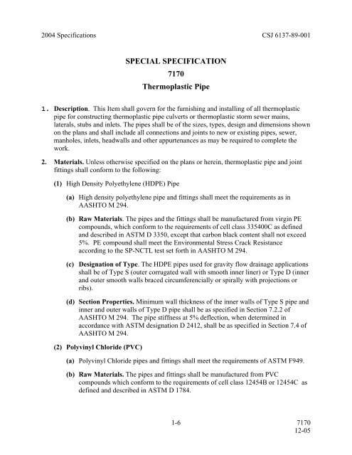
2004 Specifications CSJ 6137-89-001<br />
<strong>SPECIAL</strong> <strong>SPECIFICATION</strong><br />
<strong>7170</strong><br />
<strong>Thermoplastic</strong> <strong>Pipe</strong><br />
1. Description. This Item shall govern for the furnishing and installing of all thermoplastic<br />
pipe for constructing thermoplastic pipe culverts or thermoplastic storm sewer mains,<br />
laterals, stubs and inlets. The pipes shall be of the sizes, types, design and dimensions shown<br />
on the plans and shall include all connections and joints to new or existing pipes, sewer,<br />
manholes, inlets, headwalls and other appurtenances as may be required to complete the<br />
work.<br />
2. Materials. Unless otherwise specified on the plans or herein, thermoplastic pipe and joint<br />
fittings shall conform to the following:<br />
(1) High Density Polyethylene (HDPE) <strong>Pipe</strong><br />
(a) High density polyethylene pipe and fittings shall meet the requirements as in<br />
AASHTO M 294.<br />
(b) Raw Materials. The pipes and the fittings shall be manufactured from virgin PE<br />
compounds, which conform to the requirements of cell class 335400C as defined<br />
and described in ASTM D 3350, except that carbon black content shall not exceed<br />
5%. PE compound shall meet the Environmental Stress Crack Resistance<br />
according to the SP-NCTL test set forth in AASHTO M 294.<br />
(c) Designation of Type. The HDPE pipes used for gravity flow drainage applications<br />
shall be of Type S (outer corrugated wall with smooth inner liner) or Type D (inner<br />
and outer smooth walls braced circumferencially or spirally with projections or<br />
ribs).<br />
(d) Section Properties. Minimum wall thickness of the inner walls of Type S pipe and<br />
inner and outer walls of Type D pipe shall be as specified in Section 7.2.2 of<br />
AASHTO M 294. The pipe stiffness at 5% deflection, when determined in<br />
accordance with ASTM designation D 2412, shall be as specified in Section 7.4 of<br />
AASHTO M 294.<br />
(2) Polyvinyl Chloride (PVC)<br />
(a) Polyvinyl Chloride pipes and fittings shall meet the requirements of ASTM F949.<br />
(b) Raw Materials. The pipes and fittings shall be manufactured from PVC<br />
compounds which conform to the requirements of cell class 12454B or 12454C as<br />
defined and described in ASTM D 1784.<br />
1-6 <strong>7170</strong><br />
12-05
(c) Section Properties. Minimum wall thickness shall be as specified in Table 1 of<br />
AASHTO F949. The pipe stiffness at 5% deflection, when determined in<br />
accordance with ASTM designation D 2412, shall be as specified in Table 6 of<br />
AASHTO F949.<br />
The manufacturer shall perform appropriate test procedures on representative samples of<br />
each type of pipe furnished, and verify that the pipe complies with the specifications. A<br />
certificate of compliance will be submitted to the Engineer for review and approval. The<br />
certificate will include the following information: manufacturing plant, date of manufacture,<br />
pipe unit mass, material distribution, pipe dimensions, water inlet area, pipe stiffness, pipe<br />
flattening, brittleness, ASTM resin cell classification, and workmanship.<br />
3. Inspection. The quality of materials, the process of manufacture, and the finished pipe will<br />
be subject to inspection and approval by the Engineer at the manufacturing plant. In<br />
addition, the finished pipe will be subject to further random inspection by the Engineer at<br />
the project site prior to and during installation.<br />
4. Marking. All pipe shall be clearly marked at intervals of not more than 12 ft, and fittings<br />
and couplings shall be clearly marked as follows:<br />
• Manufacturer’s name or trade mark.<br />
• Nominal size.<br />
• Specification designation (e.g. AASHTO M 294 or ASTM F949).<br />
• Plant designation code.<br />
• Date of manufacture.<br />
5. Joints. Joints shall be installed such that the connection of pipe sections will form a<br />
continuous line free from irregularities in the flow line.<br />
Suitable joints are the following:<br />
• Integral Bell and Spigot. The bell shall overlap a minimum of two corrugations of the<br />
spigot end when full engaged. The spigot end shall have an O-ring gasket that meets<br />
ASTM F 477: Specification for Elastomeric Seals (Gaskets) for Joining Plastic <strong>Pipe</strong>.<br />
• Exterior Bell and Spigot. The bell shall be fully welded to the exterior of the pipe and<br />
overlap the spigot end so that the flow lines and ends match when fully engaged. The<br />
spigot end shall have an O-ring gasket that meets ASTM F 477: Specification for<br />
Elastomeric Seals (Gaskets) for Joining Plastic <strong>Pipe</strong>.<br />
Joints definitions are the following:<br />
• Soiltight Joints – Joints meeting the soiltightness definition in accordance with AASHTO<br />
Standard Specifications for Highway Bridge Section 26.4.2.4.<br />
• Watertight Joints – Joints meeting the requirements of ASTM 3212.<br />
If no joint type is specified, a watertight joint shall be provided.<br />
2-6 <strong>7170</strong><br />
12-05
6. Construction Methods. The location of the pipe shall be constructed at locations shown on<br />
the plans or as directed by the Engineer.<br />
Only trench installation of thermoplastic pipe will be permitted.<br />
(1) Excavation. All excavation shall be in accordance with the requirements of Item 400,<br />
"Excavation and Backfill for Structures".<br />
The width of the trench for pipe installation shall be sufficient, but no greater than<br />
necessary, to ensure working room to properly and safely place and compact haunching<br />
and other embedment materials. The space between the pipe and trench wall must be<br />
wider than the compaction equipment used in the pipe zone.<br />
When Type I backfill is used, the minimum trench width is the pipe outside diameter<br />
plus 12 inches.<br />
When Type II or Type III backfill is used, the minimum trench width shall be as<br />
specified in Table I.<br />
Table I<br />
Minimum Trench Width<br />
Nominal <strong>Pipe</strong> Diameter Minimum Trench Width<br />
Inches Inches<br />
18 44<br />
24 54<br />
30 66<br />
36 78<br />
42 84<br />
48 90<br />
(2) Installation in Embankment. If any portion of the pipe projects above the existing<br />
ground level, an embankment shall be constructed as shown in the plans or as directed<br />
by the Engineer for a distance outside each side of the pipe location of not less than five<br />
times the diameter and to a minimum elevation of 2 feet above the top of the pipe. The<br />
trench shall then be excavated to a width as specified in section 6.1 above. In areas of<br />
high water table, the thermoplastic pipe shall be installed in accordance with the<br />
manufacturer’s recommendations to prevent pipe floatation.<br />
(3) Shaping and Bedding. The pipe shall be bedded in a foundation of compacted<br />
cohesionless material, such as sand, crushed stone, or pea gravel, with a maximum size<br />
not exceeding 3/8". This material shall extend a minimum of 6 inches below the<br />
outermost corrugations or ribs, and shall be carefully and accurately shaped to fit the<br />
lowest part of the pipe exterior for a least 10 percent of the overall height. When<br />
requested by the Engineer, the Contractor shall furnish a template for each size and<br />
shape of pipe to be placed for use in checking the shaping of the bedding. The template<br />
shall consist of a thin plate or board cut to match the lower half of the cross section of<br />
the pipe.<br />
(4) Handling and Storage. Store pipe above ground on adequate blocking. Keep pipe<br />
clean and fully drained at all times during storage. Store PVC pipe and fittings out of<br />
3-6 <strong>7170</strong><br />
12-05
direct sunlight. Handling and storage of thermoplastic pipe shall be in accordance with<br />
the pipe manufacturer’s instructions. Proper facilities shall be provided for hoisting and<br />
lowering pipe into the trench without damaging the pipe or disturbing the bedding or the<br />
walls of the trench.<br />
(5) Laying <strong>Pipe</strong>. Unless otherwise authorized by the Engineer, the laying of pipes on the<br />
bedding shall be started at the outlet end with the separate sections firmly joined<br />
together. Proper facilities shall be provided for hoisting and lowering the section of pipe<br />
into the trench without damaging the pipe or disturbing the bedding and the sides of the<br />
trench. Any pipe which is not in alignment or which shows any undue settlement after<br />
laying shall be removed and relayed at the Contractor's expense.<br />
Multiple installation of thermoplastic pipe shall be laid with the center lines of<br />
individual barrels parallel. Unless otherwise indicated on the plans, the following clear<br />
distances between outer surfaces of adjacent pipes shall be maintained:<br />
Nominal <strong>Pipe</strong> Diameter Clear Distance Between <strong>Pipe</strong>s<br />
18” 1’-2”<br />
24” 1’-5”<br />
30” 1’-8”<br />
36” 1’-11”<br />
42” 2’-2”<br />
48” 2’-5”<br />
(6) Reuse of Existing Appurtenance. When existing appurtenances are specified on the<br />
plans for reuse, the portion to be reused shall be severed from the existing culvert and<br />
moved to the new position previously prepared, by approved methods.<br />
Connections shall conform to the requirements for joining sections of pipes as indicated<br />
herein or as shown on the plans. Any headwalls and any aprons or pipe attached to the<br />
headwall that are damaged during moving operations shall be restored to their original<br />
condition at the Contractor's expense. The Contractor, if he so desires, may remove and<br />
dispose of the existing headwalls and aprons and construct new headwalls at his own<br />
expense, in accordance with the pertinent specifications and design indicated on the<br />
plans or as furnished by the Engineer.<br />
(7) Sewer Connections and Stub Ends. Connections of pipe sewer to existing sewers or<br />
sewer appurtenance shall be as shown on the plans or as directed by the Engineer. The<br />
bottom of the existing structure shall be mortared or concreted if necessary, to eliminate<br />
any drainage pockets created by the new connection. Where the sewer is connected into<br />
existing structures, which are to remain in service, any damage to the existing structure<br />
resulting from making the connection shall be restored by the Contractor to the<br />
satisfaction of the Engineer. Stub ends, for connections to future work not shown on the<br />
plans, shall be sealed by installing watertight plugs into the free end of the pipe.<br />
(8) Backfilling. Backfill from the pipe bedding up to 1 foot above the top of the pipe is<br />
critical for the successful performance of the pipe. It provides necessary structural<br />
support to the pipe and controls pipe deflection. Therefore, special care is to be taken in<br />
the placement and compaction of the backfill material. Special emphasis is to be placed<br />
4-6 <strong>7170</strong><br />
12-05
upon the need for obtaining uniform backfill material and uniform compacted density<br />
throughout the length of the pipe, so that unequal pressure will be avoided. Extreme<br />
care should be taken to insure proper backfill under the pipe in the haunch zone.<br />
Backfill material shall meet the following specifications.<br />
• Type I - Backfill shall consist of flowable fill in accordance with Special<br />
Specification Item 401, "Flowable Backfill". The flowable backfill shall be placed<br />
across the entire width of the trench and shall maintain a minimum depth of 12<br />
inches above the pipe. A minimum of 24 hours shall elapse prior to backfilling the<br />
remaining portion of the trench with other backfill material in accordance with Item<br />
400, “Excavation and Backfill for Structures”.<br />
• Type II - Backfill shall consist of cement stabilized backfill in accordance with<br />
Article Section 400.3.C.4. Cement stabilized backfill shall be placed and compacted<br />
to ensure that all voids are filled completely.<br />
• Type III. Backfill consists of hard, durable, clean granular material that is free of<br />
organic matter, clay lumps, and other deleterious matter. Such backfill shall meet<br />
the gradation requirements shown in Table II. The backfill material shall be placed<br />
along both sides of the completed structure(s) to a depth of 12 inches above the<br />
pipe. The backfill shall be placed in uniform layers not exceeding 6 inches in depth<br />
(loose measurement), wetted if required, and thoroughly compacted between<br />
adjacent structures and between the structure and the sides of the trench. Until a<br />
minimum cover of 12 inches is obtained, only hand operated tamping equipment<br />
will be allowed within vertical planes 2 feet beyond the horizontal projection of the<br />
outside surfaces of the structure.<br />
Table II<br />
Gradation Requirements for Type III Backfill Material<br />
Sieve Number Percent Retained<br />
(Cumulative)<br />
1 inch 0-5<br />
7/8 inch 0-35<br />
1/2 inch 0-75<br />
3/8 inch 0-95<br />
No. 4 35-100<br />
No. 10 50-100<br />
No. 200 90-100<br />
If Type III backfill is utilized, place filter fabric between the native soil and the backfill.<br />
Filter fabric shall conform to the requirements of DMS-6200, Type 1.<br />
(9) Protection of the <strong>Pipe</strong>. Unless otherwise shown on the plans or permitted in writing by<br />
the Engineer, no heavy earth moving equipment will be permitted over the structure<br />
until a minimum of 4 feet of compacted fill (permanent or temporary) has been placed<br />
over the top of the structure.<br />
Prior to adding each new layer of loose backfill material, until a minimum of 12 inches<br />
of cover is obtained, an inspection will be made of the inside periphery of the structure<br />
5-6 <strong>7170</strong><br />
12-05
for local or unequal deformation caused by improper construction methods. Evidence of<br />
such will be reason for such corrective measures as may be directed by the Engineer.<br />
<strong>Pipe</strong> damaged by the Contractor shall be removed and replaced by the Contractor at no<br />
additional cost to the State.<br />
7. Measurement. This Item will be measured by the linear foot. Such measurements will be<br />
made between the ends of the barrel along its flow line, exclusive of safety end treatments.<br />
Safety end treatments shall be measured in accordance with Item 467, "Safety End<br />
Treatment". Where spurs, branches or connections to existing pipe lines are involved,<br />
measurement of the spur or new connecting pipe will be made from the intersection of its<br />
flow line with the outside surface of the pipe into which it connects. Where inlets,<br />
headwalls, catch basins, manholes, junction chambers, or other structures are included in<br />
lines of pipe, that length of pipe tying into the structure wall will be included for<br />
measurement but no other portion of the structure length or width will be so included.<br />
For multiple pipes, the measured length will be the sum of the lengths of the barrels,<br />
measured as prescribed above.<br />
This is a plans quantity measurement Item and the quantity to be paid for will be that<br />
quantity shown in the proposal and on the "Estimate and Quantity" sheet of the contract<br />
plans, except as may be modified by Article 9.2. If no adjustment of quantities is required<br />
additional measurements or calculations will not be required.<br />
8. Payment. The work performed and materials furnished in accordance with this Item and<br />
measured as provided under "Measurement" will be paid for at the unit price bid for<br />
"<strong>Thermoplastic</strong> <strong>Pipe</strong>” of the size and backfill type specified. This price shall be full<br />
compensation for furnishing, hauling, placing and joining of pipes; for all connections to<br />
new or existing structures; for moving and reusing headwalls where required; for removing<br />
and disposing of portions of existing structures as required; for cutting of pipe ends on skew;<br />
and for all labor, tools, equipment and incidentals necessary to complete the work.<br />
Excavation, bedding, and backfill will be paid for in accordance with Item 400, “Excavation<br />
and Backfill for Structures”.<br />
Type I backfill will be paid in accordance with Item 401, “Flowable Backfill”.<br />
Safety end treatment will be paid for in accordance with Item 467, "Safety End Treatment".<br />
6-6 <strong>7170</strong><br />
12-05