2 - SMG - Slotted Microwave Guide - VAHLE, Inc
2 - SMG - Slotted Microwave Guide - VAHLE, Inc
2 - SMG - Slotted Microwave Guide - VAHLE, Inc

Create successful ePaper yourself
Turn your PDF publications into a flip-book with our unique Google optimized e-Paper software.
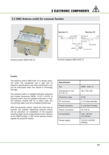
2.2 <strong>SMG</strong> Antenna switch for crossover function<br />
Antenna switch <strong>SMG</strong>-AUS 12<br />
Function<br />
The antenna switch <strong>SMG</strong>-AUS 12 is always required<br />
when the waveguide has a gap due to<br />
system’s specifications and data transmission can<br />
not be interrupted when the vehicle is traversing<br />
this gap.<br />
The antenna switch is installed between antennas<br />
and mobile transceiver (SEM). 12-24 V AC/DC is<br />
required which may be supplied externally or from<br />
the interface module SM 10. In either case, the<br />
connecting cable must be a shielded twisted pair.<br />
With the proximity switch, which the client has to<br />
provide, the position depending antenna switch<br />
will be activated. An installation of the required<br />
switching flags can be made directly at the T-groove<br />
of the <strong>SMG</strong>T-profile. A LED at the antenna switch<br />
signals the actual RF-status.<br />
2 ELECTRONIC COMPONENTS<br />
Section A Section B<br />
Function diagram <strong>SMG</strong>-AUS 12<br />
Specification<br />
Typ <strong>SMG</strong> - AUS 12<br />
Dimensions in mm 48 x 120 x 68<br />
(H x B x T)<br />
Protection class IP 50<br />
RF-connector 3 x N-Type (female)<br />
Power connector 9 -pol Sub-D (male)<br />
Sensor connector M 12 (E 2)<br />
Consumption max. 100 mA<br />
w/o Sensor<br />
Switching flag<br />
Power supply 12V-24 V AC/DC<br />
floating<br />
11