Enclosed Conductor System MKH
Enclosed Conductor System MKH
Enclosed Conductor System MKH

You also want an ePaper? Increase the reach of your titles
YUMPU automatically turns print PDFs into web optimized ePapers that Google loves.
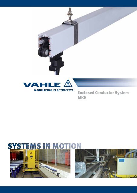
Mobilizing ElECtriCity!<br />
<strong>Enclosed</strong> <strong>Conductor</strong> <strong>System</strong><br />
<strong>MKH</strong>
<strong>MKH</strong>D/<strong>MKH</strong>F/<strong>MKH</strong>S<br />
2
<strong>Enclosed</strong> conductor system <strong>MKH</strong><br />
content page<br />
Description of the conductor system ....................................3<br />
Technical Data .....................................................................5<br />
Technicall data & standard sections .....................................6<br />
Types & order numbers ........................................................7<br />
Sections & Sealing strips .....................................................9<br />
Hangers & end sections .....................................................10<br />
Brackets ...........................................................................11<br />
Jointing material & End feeds .............................................12<br />
Line feeds .........................................................................13<br />
Heating .............................................................................17<br />
Contact sections, Turntables and Switches .........................19<br />
Entry funnel ......................................................................20<br />
Description of the conductor system<br />
Powerail <strong>MKH</strong>… is a totally enclosed conductor system for indoor<br />
and outdoor use. The insulated housing can accommodate<br />
different copper sections.<br />
Type <strong>MKH</strong>D in 6 to 10 copper conductor version,<br />
continuous copper strips 40 - 160 A<br />
(copper strips come as separate items as coils).<br />
Type <strong>MKH</strong>F in 6- and 8-conductor version,<br />
with preassembled copper conductors and<br />
spring loaded connectors from 40 to 100 A.<br />
Type <strong>MKH</strong>S in 6- and 8-conductor version,<br />
with preassembled copper conductors and<br />
bolted joints from 40 to 200 A.<br />
A compact design, corrosion resistance and easy installation are<br />
the main characteristics.<br />
The <strong>MKH</strong> complies with VDE, european and international standards<br />
as well as accident prevention regulations. It is protected to IP 23<br />
standards.<br />
The <strong>MKH</strong> can be supplied with sealing strip and heating system.<br />
The powerail with sealing strip is protected to IP 24 standards and<br />
EN 60529 (0470, part 1) regulation.<br />
Collectors are safe against touch only when fully entered into the<br />
powerail.<br />
If there is the possibility to touch live parts by hand, ie. collectors<br />
that might leave the powerail during operation, provide safety<br />
barrier or disconnect mains. This is valid only for a supply voltage<br />
exceeding 24 V AC or 60 VDC.<br />
If a conductor is used as N please note VDE 0100 part 430.<br />
Applications<br />
Mobile power feeding of overhead cranes, monorail systems,<br />
electric hoists, electric power tools, machine tools, automated<br />
storage and retrieval systems, assembly and test lines, hangar<br />
doors, studio & station lighting systems and many others.<br />
Approvals<br />
UL-approved<br />
Housing<br />
Color grey, plastic housing for 6 to 10 conductors.<br />
Standard section 4 m. Other sections are available.<br />
The ground conductor is identified by international color code.<br />
Phase reversing prevented by design of the collector and housing.<br />
Higher number of conductors possible by combination of several<br />
powerails.<br />
Couplings<br />
Through plastic joint caps.<br />
Feed Sets<br />
Through line feeds or end feeds.<br />
End sections<br />
End section incl. end cap for <strong>MKH</strong>D and<br />
end caps for <strong>MKH</strong>F and <strong>MKH</strong>S.<br />
<strong>MKH</strong>D/<strong>MKH</strong>F/<strong>MKH</strong>S<br />
Transfer guides .................................................................21<br />
Removal sections ..............................................................22<br />
<strong>Conductor</strong> dead sections ...................................................23<br />
Anti-condensation sections ...............................................24<br />
Expansion Sections ...........................................................25<br />
Expansion Sections ...........................................................26<br />
Collectors ..........................................................................27<br />
Tow arms ..........................................................................30<br />
Flat copper & cable glands .................................................31<br />
Assembling tools ..............................................................32<br />
Example for ordering .........................................................33<br />
Spare parts .......................................................................34<br />
Questionnaire ...................................................................35<br />
Hangers<br />
The brackets are installed to the crane track (see page 11).<br />
The conductor rails are located in sliding and fixpoint hangers.<br />
Max. support distance with the following ambient temperatures:<br />
Indoor systems and covered<br />
outdoor systems: ≤ 35° C = 2,00 m<br />
Indoor and outdoor systems<br />
with and without heating: > 35° C = 1,33 m<br />
Expansion during temperature fluctuation<br />
Housing-expansion section without electrical isolation for <strong>MKH</strong>D.<br />
Expansion section (Housing and Cu) without electrical isolation for<br />
<strong>MKH</strong>F and <strong>MKH</strong>S.<br />
3
<strong>MKH</strong>D/<strong>MKH</strong>F/<strong>MKH</strong>S<br />
Anti-condensation sections<br />
For combined indoor/outdoor applications use anti-condensation<br />
sections. They do not interrupt electric conductors.<br />
Contact sections, turntables, switches<br />
Powerail for working areas and transfer applications<br />
see pages 20 & 21<br />
Sectionalizing<br />
<strong>Conductor</strong> dead sections are electrical interrupts of the conductor.<br />
Under normal operating conditions a cross over with collectors to<br />
switch the voltage off or on is only allowed with low power ratings<br />
(control current).<br />
The conductors can be seperated through air gaps (5 mm) or<br />
insulating pieces (35 mm). With the air gap the collector carbon<br />
bridges the gap, e.g. for mains.<br />
The insulating piece is longer than the carbon and each Powerail<br />
section can be separated electrically, e.g. for control.<br />
Collectors<br />
The current collectors are made of re-inforced polyester fiberglass,<br />
for high strength and light weight. Spring loaded carbon brushes<br />
maintain uniform contact. Connecting cables and hinged or flexible<br />
towing arms included.<br />
Electrical properties<br />
Max. continuous<br />
current<br />
200 A<br />
(with 80% duty cycle)<br />
Mechanical properties<br />
Flexible strength Tensile<br />
strength<br />
Nominal voltage (UL) Dielectric strength Spec. resistance Surface resistance Leakage resistance<br />
690 V (600 V) IEC 60243<br />
30-40 KV/mm<br />
Temperature range<br />
(ambient):<br />
IEC 60093<br />
5 x 10 15 Ω/cm<br />
75 N/mm 2 ± 10 % 40 N/mm 2 ± 10 - 30 °C bis + 60 °C flame retardant DIN<br />
41 02 - Klasse B 1;<br />
self extinguishing<br />
Consider the voltage drop calculation to maintain the limits established by the motor manufacturers!<br />
AC: ΔU = √ 3 x I x l x Z<br />
DC: ΔU 1 =2 l x I x R<br />
ΔU = 2 ΔU ∧ 100 1<br />
V<br />
ΔU 1 = Voltage drop [V] R = Resistance [Ω/1000 m]<br />
ΔU 2 = Voltage drop in % l = Power feed length [m]<br />
I = Ampere load [A] L = <strong>System</strong> length [m]<br />
With following system requirements double collectors<br />
have to be used:<br />
- Transfers with switches and turntables<br />
- low voltages, frequency controlled drives<br />
- Transmission of data- and/or emergency stop signals<br />
- high electrical loads<br />
The length of the collector cable may not exceed 3 m if the added<br />
overcurrent protection device is not designed for the load capacity<br />
of this cable. Please refer also to regulations VDE 0100, part 430<br />
and EN 60204-32.<br />
Please note: For use in galvanizing and pickling plants, under<br />
agressive conditions and low voltage applications we would<br />
appreciate receiving detailled information,especially of the<br />
environmental conditions.<br />
For quotations and order processing including Powerail systems<br />
with curves, dead sections, turntables, switches etc. we require<br />
your drawings or sketches. Please use our questionnaire, page 35.<br />
IEC 60093 10 13 Ω EN 60112<br />
CTI 400-2,7<br />
Combustibility Resistance to chemicals (at + 45 °C)<br />
Gasoline, Mineral Oil, Grease, Sulphuric acid<br />
50 %, Caustic soda 25 % & 50 %<br />
Hydro-chloric acid, concentrated<br />
l = L power feed located at the end of the system<br />
l = L/2 power feed located at the center of the system<br />
l = L/4 power feed located at both ends of the system<br />
l = L/6 power feed located at L/6 from each end<br />
of the system<br />
Z = Impedance [Ω/1000 m]<br />
V = Voltage rating [V]<br />
The total ampere load is determined from the nominal rated current of all motors working simultaneously on the same feed section of your<br />
electrification system. A diversity factor of 0,5-0,9 can be considered.<br />
The conductor size and/or number of feed points should be increased or booster cables should be used in parallel in case the drop is<br />
exceeding the limitations.<br />
4
technical Data<br />
Cross sections: (1)<br />
In case of using a neutral conductor<br />
copper pos.1 will be taken.<br />
Layout of the system on request<br />
(please see page 3)<br />
Type (2)<br />
(HS with PE<br />
SS without PE)<br />
No. of<br />
conductors<br />
Copper cross section mm 2 Ampere rating<br />
with<br />
Phase<br />
L1, L2, L3<br />
L1<br />
(3)<br />
<strong>MKH</strong><br />
6 poles<br />
Control-line<br />
35 °C<br />
L1, L2, L3<br />
100% A<br />
Nominal<br />
voltage V<br />
Impedance<br />
at<br />
50 Hz<br />
20 °C<br />
Ώ/1000 m<br />
Resistance<br />
at<br />
20 °C<br />
Ώ/1000 m<br />
<strong>MKH</strong> ... 6 / 40 - HS 6 3 x 10 10 2 x 10 40 690 1,73 1,72 30<br />
<strong>MKH</strong> ... 6 / 40 - SS 6 6 x 10 40 690 1,73 1,72 30<br />
<strong>MKH</strong> ... 6 / 63 - HS 6 3 x 14 14 2 x 10 63 690 1,26 1,25 30<br />
<strong>MKH</strong> ... 6 / 100 - HS 6 3 x 26 26 2 x 10 100 690 0,71 0,69 30<br />
<strong>MKH</strong> ... 6 / 140 - HS 6 3 x 33 26 2 x 10 140 (3) 690 0,57 0,55 30<br />
<strong>MKH</strong> ... 6 / 160 - HS 6 3 x 42 26 2 x 10 160 (3) 690 0,46 0,43 30<br />
<strong>MKH</strong> ... 6 / 200 - HS (4) 6 3 x 51 26 2 x 10 200 (3) 690 0,38 0,35 30<br />
<strong>MKH</strong> ... 7 / 40 - HS 7 3 x 10 10 2 x 10 1 x 11 40 690 1,73 1,72 30<br />
<strong>MKH</strong> ... 7 / 40 - SS 7 6 x 10 1 x 11 40 690 1,73 1,72 30<br />
<strong>MKH</strong> ... 7 / 63 - HS 7 3 x 14 14 2 x 10 1 x 11 63 690 1,26 1,25 30<br />
<strong>MKH</strong> ... 7 / 100 - HS 7 3 x 26 26 2 x 10 1 x 11 100 690 0,71 0,69 30<br />
<strong>MKH</strong> ... 7 / 140 - HS 7 3 x 33 26 2 x 10 1 x 11 140 (3) 690 0,57 0,55 30<br />
<strong>MKH</strong> ... 7 / 160 - HS 7 3 x 42 26 2 x 10 1 x 11 160 (3) 690 0,46 0,43 30<br />
<strong>MKH</strong> ... 7 / 200 - HS (4) 7 3 x 51 26 2 x 10 1 x 11 200 (3) 690 0,38 0,35 30<br />
<strong>MKH</strong> ... 8 / 40 - HS 8 3 x 10 10 2 x 10 2 x 11 40 690 1,73 1,72 30<br />
<strong>MKH</strong> ... 8 / 40 - SS 8 6 x 10 2 x 11 40 690 1,73 1,72 30<br />
<strong>MKH</strong> ... 8 / 63 - HS 8 3 x 14 14 2 x 10 2 x 11 63 690 1,26 1,25 30<br />
<strong>MKH</strong> ... 8 / 100 - HS 8 3 x 26 26 2 x 10 2 x 11 100 690 0,71 0,69 30<br />
<strong>MKH</strong> ... 8 / 140 - HS 8 3 x 33 26 2 x 10 2 x 11 140 (3) 690 0,57 0,55 30<br />
<strong>MKH</strong> ... 8 / 160 - HS 8 3 x 42 26 2 x 10 2 x 11 160 (3) 690 0,46 0,43 30<br />
<strong>MKH</strong> ... 8 / 200 - HS (4) 8 3 x 51 26 2 x 10 2 x 11 200 (3) 690 0,38 0,35 30<br />
(1) Numbers in paranthesis apply to control line<br />
(2) Complete types e.g. <strong>MKH</strong>S 7/63 HS for 7 poles with bolted joints<br />
(3) 80% duty cycle<br />
(4) only for <strong>MKH</strong>S<br />
1<br />
(2)<br />
L3<br />
(6)<br />
2<br />
(5)<br />
L2<br />
(1) (4)<br />
3 (7)<br />
L1<br />
(3)<br />
<strong>MKH</strong><br />
7 poles<br />
1<br />
(2)<br />
L3<br />
(6)<br />
2<br />
(5)<br />
L2<br />
(1) (4)<br />
<strong>MKH</strong>D/<strong>MKH</strong>F/<strong>MKH</strong>S<br />
3 (7) 4 (8)<br />
L1<br />
(3)<br />
<strong>MKH</strong><br />
8 poles<br />
1<br />
(2)<br />
L3<br />
(6)<br />
2<br />
(5)<br />
L2<br />
(1) (4)<br />
Leakage<br />
distance<br />
mm<br />
5
<strong>MKH</strong>D/<strong>MKH</strong>F/<strong>MKH</strong>S<br />
technicall data & standard sections<br />
Cross sections: (1)<br />
In case of using a neutral conductor<br />
copper pos.1 will be taken.<br />
Layout of the system on request<br />
(please see page 3)<br />
Type No. of<br />
conductors<br />
Copper cross section mm 2 Ampere rating<br />
with<br />
Phase<br />
L1, L2, L3<br />
Control-line<br />
35 °C<br />
L1, L2, L3 100%<br />
A<br />
Nominalvoltage<br />
V<br />
Impedance<br />
at<br />
50 Hz<br />
20 °C<br />
Ώ/1000 m<br />
Resistance<br />
at<br />
20 °C<br />
Ώ/1000 m<br />
<strong>MKH</strong>D 9 / 40 - HS 9 3 x 10 10 2 x 10 3 x 11 40 690 1,73 1,72 30<br />
<strong>MKH</strong>D 9 / 40 - SS 9 6 x 10 3 x 11 40 690 1,73 1,72 30<br />
<strong>MKH</strong>D 9 / 63 - HS 9 3 x 14 14 2 x 10 3 x 11 63 690 1,26 1,25 30<br />
<strong>MKH</strong>D 9 / 100 - HS 9 3 x 26 26 2 x 10 3 x 11 100 690 0,71 0,69 30<br />
<strong>MKH</strong>D 9 / 140 - HS 9 3 x 33 26 2 x 10 3 x 11 140 (2) 690 0,57 0,55 30<br />
<strong>MKH</strong>D 9 / 160 - HS 9 3 x 42 26 2 x 10 3 x 11 160 (2) 690 0,46 0,43 30<br />
<strong>MKH</strong>D 10 / 40 - HS 10 3 x 10 10 2 x 10 4 x 11 40 690 1,73 1,72 30<br />
<strong>MKH</strong>D 10 / 40 - SS 10 6 x 10 4 x 11 40 690 1,73 1,72 30<br />
<strong>MKH</strong>D 10 / 63 - HS 10 3 x 14 14 2 x 10 4 x 11 63 690 1,26 1,25 30<br />
<strong>MKH</strong>D 10 / 100 - HS 10 3 x 26 26 2 x 10 4 x 11 100 690 0,71 0,69 30<br />
<strong>MKH</strong>D 10 / 140 - HS 10 3 x 33 26 2 x 10 4 x 11 140 (2) 690 0,57 0,55 30<br />
<strong>MKH</strong>D 10 / 160 - HS 10 3 x 42 26 2 x 10 4 x 11 160 (2) 690 0,46 0,43 30<br />
(1) Numbers in paranthesis apply to control line<br />
(2) 80% duty cycle<br />
Standard sections<br />
type <strong>MKH</strong>D for continuous copper strips<br />
6<br />
88<br />
L1 L3<br />
(3)<br />
<strong>MKH</strong><br />
(6)<br />
e.g. 6 poles<br />
1<br />
(2)<br />
A<br />
left side right side<br />
A<br />
A - A<br />
56,2<br />
2<br />
(5)<br />
L2<br />
(1) (4)<br />
Standard section e.g. 4 m<br />
safety-web<br />
yellow<br />
(dark grey)<br />
green<br />
(dark grey)<br />
type <strong>MKH</strong>F with plug-in joints, factory assembled<br />
left side<br />
right side<br />
type <strong>MKH</strong>S with bolted joints, factory assembled<br />
left side<br />
3 (7) 4 (8)<br />
L1<br />
(3)<br />
<strong>MKH</strong><br />
9 poles<br />
1<br />
(2)<br />
L3<br />
(6)<br />
2<br />
(5)<br />
L2<br />
(1) (4)<br />
9 (9)<br />
A<br />
A<br />
Standard section e.g. 4 m<br />
A<br />
A<br />
Standard section e.g. 4 m<br />
L1<br />
(3)<br />
right side<br />
3 (7) 4 (8)<br />
1<br />
(2)<br />
L2<br />
(1)<br />
L3<br />
(6)<br />
<strong>MKH</strong><br />
10 poles<br />
2<br />
(5)<br />
(4)<br />
10 (10) 9 (9)<br />
Leakage<br />
distance<br />
mm
types & order numbers<br />
type <strong>MKH</strong>D<br />
with continuous copper strips,<br />
to be drawn in during installation.<br />
Type (1) Weight kg/m Order-No.<br />
<strong>MKH</strong>D- ... HS 1,129 262 50•<br />
<strong>MKH</strong>D- ... SS 1,129 262 51•<br />
type <strong>MKH</strong>F<br />
with factory assembled copper strips<br />
and plug-in joints (40 – 100 A)<br />
Type (1) Weight kg/m Order-No.<br />
<strong>MKH</strong>F 6 / 40 - ... HS 1,736 262 03•<br />
<strong>MKH</strong>F 6 / 40 - ... SS 1,736 262 02•<br />
<strong>MKH</strong>F 6 / 63 - ... HS 1,968 262 04•<br />
<strong>MKH</strong>F 6 / 100 - ... HS 2,226 262 05•<br />
<strong>MKH</strong>F 7 / 40 - ... HS 1,846 262 07•<br />
<strong>MKH</strong>F 7 / 40 - ... SS 1,846 262 06•<br />
<strong>MKH</strong>F 7 / 63 - ... HS 2,077 262 08•<br />
<strong>MKH</strong>F 7 / 100 - ... HS 2,321 262 09•<br />
<strong>MKH</strong>F 8 / 40 - ... HS 1,956 262 11•<br />
<strong>MKH</strong>F 8 / 40 - ... SS 1,956 262 10•<br />
<strong>MKH</strong>F 8 / 63 - ... HS 2,167 262 12•<br />
<strong>MKH</strong>F 8 / 100 - ... HS 2,430 262 13•<br />
(1) Complete types e.g. <strong>MKH</strong>D - 4 HS for 4 m with PE, Order-No. 262 504<br />
<strong>MKH</strong>F 8 / 40 - 4 HS for 4 m with PE, Order-No. 262 114<br />
• The last number of the order specifies the section length. Please suffix the order number with 1, 2, 3, 4.<br />
<strong>MKH</strong>D/<strong>MKH</strong>F/<strong>MKH</strong>S<br />
<strong>MKH</strong>D/<strong>MKH</strong>F<br />
7
<strong>MKH</strong>D/<strong>MKH</strong>F/<strong>MKH</strong>S<br />
<strong>MKH</strong>S<br />
types & order numbers<br />
type <strong>MKH</strong>S<br />
with factory assembled copper strips<br />
and bolted joints (40 – 200 A)<br />
Type (1) Weight kg/m Order-No.<br />
<strong>MKH</strong>S 6 / 40 - ... HS 1,780 262 18•<br />
<strong>MKH</strong>S 6 / 40 - ... SS 1,780 262 17•<br />
<strong>MKH</strong>S 6 / 63 - ... HS 2,009 262 19•<br />
<strong>MKH</strong>S 6 / 100 - ... HS 2,249 262 20•<br />
<strong>MKH</strong>S 6 / 140 - ... HS 2,423 262 21•<br />
<strong>MKH</strong>S 6 / 160 - ... HS 2,752 262 22•<br />
<strong>MKH</strong>S 6 / 200 - ... HS 2,995 262 23•<br />
<strong>MKH</strong>S 7 / 40 - ... HS 1,896 262 25•<br />
<strong>MKH</strong>S 7 / 40 - ... SS 1,896 262 24•<br />
<strong>MKH</strong>S 7 / 63 - ... HS 2,127 262 26•<br />
<strong>MKH</strong>S 7 / 100 - ... HS 2,374 262 27•<br />
<strong>MKH</strong>S 7 / 140 - ... HS 2,545 262 28•<br />
<strong>MKH</strong>S 7 / 160 - ... HS 2,868 262 29•<br />
<strong>MKH</strong>S 7 / 200 - ... HS 3,064 262 30•<br />
<strong>MKH</strong>S 8 / 40 - ... HS 2,013 262 32•<br />
<strong>MKH</strong>S 8 / 40 - ... SS 2,013 262 31•<br />
<strong>MKH</strong>S 8 / 63 - ... HS 2,245 262 33•<br />
<strong>MKH</strong>S 8 / 100 - ... HS 2,488 262 34•<br />
<strong>MKH</strong>S 8 / 140 - ... HS 2,661 262 35•<br />
<strong>MKH</strong>S 8 / 160 - ... HS 2,985 262 36•<br />
<strong>MKH</strong>S 8 / 200 - ... HS 3,228 262 37•<br />
(1) Complete types e.g. <strong>MKH</strong>S 8 / 40 - 4 HS for 4m with PE, Order-No. 262 324<br />
• The last number of the order specifies the section length. Please suffix the order number with 1, 2, 3, 4.<br />
8
Sections & Sealing strips<br />
Curves<br />
Min. bending radius, horizontal = 1000 mm<br />
max. length L = 3600 mm<br />
max. )<br />
120 °<br />
Smallest vertical radius = on request<br />
Type Surchase for bending on request Order-No.<br />
<strong>MKH</strong> horizontal curve for SI and SA (1) 234 547<br />
<strong>MKH</strong> vertical curve for VRO and VU (2) 234 620<br />
(1) SI = Safety-web inside (2) VRO = Vertical radius upwards<br />
(1) SA = Safety web outside (2) VRU = Vertical radius downwards<br />
Safety web will be mounted in direction of track.<br />
Changes in measurements of curves have to be mentioned for replacement orders.<br />
Sealing strip including accessories<br />
Type Description Order - No.<br />
Sealing strip (3) 600 551<br />
Fixing clamp for sealing strip (1 per end) 236 105<br />
Joint for coupling the sealing strip (2 per joint) 258 300<br />
Mounting glider EZRD for sealing strip 234 552<br />
Sealing strip slide plate for collector MSWA 236 625<br />
(3) The max. single length is 40 m long. For longer distances joint laces are necessary.<br />
For each meter system length 2 m sealing strip to be ordered. The delivery will be in pairs.<br />
Not available for 9- and 10-pole systems.<br />
Bearing surface<br />
of the collector<br />
VRU VRO<br />
approx. 105<br />
<strong>MKH</strong>D/<strong>MKH</strong>F/<strong>MKH</strong>S<br />
88<br />
L1<br />
(3)<br />
1<br />
(2)<br />
<strong>MKH</strong><br />
e.g. 6 poles<br />
L3<br />
(6)<br />
2<br />
(5)<br />
L2<br />
(1) (4)<br />
HR for SA HR for SI<br />
3 (7)<br />
56,2<br />
4 (8)<br />
L1<br />
L3<br />
(3)<br />
(6)<br />
<strong>MKH</strong><br />
e.g. 8 poles<br />
1<br />
2<br />
(2)<br />
(5)<br />
L2<br />
(1) (4)<br />
safety-web<br />
yellow<br />
(dark grey)<br />
green<br />
(dark grey)<br />
2 sealing strips<br />
9
<strong>MKH</strong>D/<strong>MKH</strong>F/<strong>MKH</strong>S<br />
<strong>MKH</strong>D/<strong>MKH</strong>F/<strong>MKH</strong>S<br />
Hangers & end sections<br />
Sliding hanger<br />
Type Weight kg Order - No.<br />
MGH 0,110 262 000<br />
MGH/K 0,110 262 003<br />
Fixpoint hanger<br />
Type Weight kg Order - No.<br />
MFH 0,150 262 001<br />
MFH/K 0,150 262 002<br />
End section (<strong>MKH</strong>D)<br />
0,3 m long<br />
Type Weight kg Execution Order - No.<br />
MHED / L 0,429 left 262 537<br />
MHED / R 0,429 right 262 536<br />
End cap (<strong>MKH</strong>F / <strong>MKH</strong>S)<br />
Type Weight kg Execution Order - No.<br />
MSES 0,286 left and right 235 141<br />
10<br />
60<br />
60<br />
90<br />
35<br />
approx. 156<br />
approx. 97<br />
35<br />
approx. 156<br />
approx. 101<br />
300<br />
empty housing<br />
110<br />
23<br />
167<br />
100
ackets<br />
view without - beam<br />
Arrangement EHK with small fixing claw<br />
Attention!<br />
Make sure that hoist wheels have<br />
enough clearance.<br />
Use small claw if necessary.<br />
- rail of EHK is identical to type S 1, Cat. 8 a<br />
fixing claw suitable<br />
for D = 6-15 mm<br />
fixing claw suitable<br />
for D = 15-25 mm<br />
Type X mm L mm B max mm Weight kg Order - No.<br />
Standard version with small fixing<br />
claw<br />
EHK 250 250 350 170 1,070 251 600 251 720<br />
EHK 300 300 400 170 1,150 251 610 251 730<br />
EHK 400 400 500 170 1,300 251 620 251 740<br />
EHK 500 500 600 170 1,450 251 630 251 750<br />
EHK 600 600 700 170 1,600 251 640 251 760<br />
EHK 700 700 800 170 1,750 251 650 251 770<br />
EHK 750 750 850 170 1,820 251 660 251 780<br />
EHK 800 800 900 170 1,900 251 670 251 790<br />
Select next larger size bracket when your -beam dimension B is more than 170 mm.<br />
30<br />
30<br />
32<br />
32<br />
max. 37<br />
max. 48<br />
D<br />
45<br />
45<br />
D<br />
D<br />
B<br />
B<br />
small fixing claw<br />
fixing claw<br />
L<br />
L<br />
ø 9<br />
<strong>MKH</strong>D/<strong>MKH</strong>F/<strong>MKH</strong>S<br />
A<br />
A<br />
A<br />
A<br />
X<br />
X<br />
Tow arm level<br />
Tow arm level<br />
25<br />
R = 10 x D D<br />
25<br />
R = 10 x D D<br />
M8<br />
M8<br />
support bracket<br />
88<br />
+ 6<br />
- 15<br />
139<br />
11<br />
+ 6<br />
- 15<br />
192<br />
19<br />
support bracket<br />
88<br />
+ 6<br />
139<br />
- 15<br />
+ 6<br />
192<br />
- 15<br />
19
<strong>MKH</strong>D/<strong>MKH</strong>F/<strong>MKH</strong>S<br />
<strong>MKH</strong>D/ <strong>MKH</strong>F / <strong>MKH</strong>S<br />
Jointing material & End feeds<br />
Joint cap, self locking (<strong>MKH</strong>D)<br />
Type Weight kg Order - No.<br />
MVMD 0,16 234 678<br />
Joint cap, self locking (<strong>MKH</strong>F / <strong>MKH</strong>S)<br />
Type Weight kg Order - No.<br />
MVMS 0,240 234 585<br />
End feed (<strong>MKH</strong>D)<br />
End feed comes loose without powerail section.<br />
It can be mounted at the left or right hand side.<br />
Electrical connection with customer supplied<br />
cable shoes to M6 terminals.<br />
Type Weight kg Cable gland<br />
(Dimensions see p. 31)<br />
End feed (<strong>MKH</strong>F / <strong>MKH</strong>S)<br />
End feed comes loose without powerail section.<br />
It can be mounted at the left or right hand side.<br />
Electrical connection with customer supplied<br />
cable shoes to M6 terminals.<br />
Type Weight kg Cable gland<br />
(Dimensions see p. 31)<br />
6 - 8 poles 9 - 10 poles<br />
Order - No.<br />
MKED 6 - 8 / 40 - 63 HS 0,707 M 25 u. M 40 235 152<br />
MKED 9 - 10 / 40 - 63 HS 0,936 M 25 u. M 40 262 538<br />
MKED 6 - 8 / 40 SS 0,647 M 25 235 157<br />
MKED 9 - 10 / 40 SS 0,870 M 25 262 539<br />
Order - No.<br />
MKES 6 - 8 / 40 - 63 HS 0,707 M 25 u. M 40 235 230<br />
MKES 6 - 8 / 40 SS 0,647 M 25 235 233<br />
12<br />
23<br />
167<br />
100<br />
110<br />
40<br />
23<br />
150<br />
167<br />
92<br />
167<br />
100<br />
100<br />
100<br />
20<br />
196<br />
156<br />
110<br />
23
line feeds<br />
Electrical connection with customer<br />
supplied cable shoes to M8 terminals.<br />
Type Weight kg Cable gland<br />
(Dimensions see p. 31)<br />
<strong>MKH</strong>D/<strong>MKH</strong>F/<strong>MKH</strong>S <strong>MKH</strong>D<br />
300150<br />
Order - No.<br />
MHGD 6 / 40 - 100 HS 2,336 M 50 and M 25 262 545<br />
MHGD 7 / 40 - 100 HS 2,413 M 50 and M 25 262 546<br />
MHGD 8 / 40 - 100 HS 2,490 M 50 and M 25 262 547<br />
MHGD 9 / 40 - 100 HS 2,550 M 50 and M 25 262 548<br />
MHGD 10 / 40 - 100 HS 2,590 M 50 and M 25 262 549<br />
MHGD 6 / 140 - 160 HS 2,340 M 50 and M 25 262 550<br />
MHGD 7 / 140 - 160 HS 2,417 M 50 and M 25 262 551<br />
MHGD 8 / 140 - 160 HS 2,494 M 50 and M 25 262 552<br />
MHGD 9 / 140 - 160 HS 2,554 M 50 and M 25 262 553<br />
MHGD 10 / 140 - 160 HS 2,594 M 50 and M 25 262 554<br />
MHGD 6 / 40 SS 2,263 M 25 262 540<br />
MHGD 7 / 40 SS 2,340 M 25 262 541<br />
MHGD 8 / 40 SS 2,422 M 25 262 542<br />
MHGD 9 / 40 SS 2,482 M 25 262 543<br />
MHGD 10 / 40 SS 2,522 M 25 262 544<br />
83<br />
1000<br />
13
<strong>MKH</strong>D/<strong>MKH</strong>F/<strong>MKH</strong>S<br />
<strong>MKH</strong>F/<strong>MKH</strong>S<br />
<strong>MKH</strong>F/<strong>MKH</strong>S<br />
line feeds<br />
Electrical connection with customer supplied cable shoes to<br />
M8 terminals.<br />
Type Weight kg Cable gland<br />
(Dimensions see p. 31)<br />
Order - No.<br />
MHGF 6 / 40 HS 2,981 M 50 and M 25 262 492<br />
MHGF 7 / 40 HS 3,180 M 50 and M 25 262 493<br />
MHGF 8 / 40 HS 3,377 M 50 and M 25 262 494<br />
MHGF 6 / 63 HS 3,212 M 50 and M 25 262 495<br />
MHGF 7 / 63 HS 3,411 M 50 and M 25 262 496<br />
MHGF 8 / 63 HS 3,608 M 50 and M 25 262 497<br />
MHGF 6 / 100 HS 3,455 M 50 and M 25 262 498<br />
MHGF 7 / 100 HS 3,654 M 50 and M 25 262 499<br />
MHGF 8 / 100 HS 3,851 M 50 and M 25 262 500<br />
MHGF 6 / 40 SS 2,913 M 25 262 489<br />
MHGF 7 / 40 SS 3,112 M 25 262 490<br />
MHGF 8 / 40 SS 3,309 M 25 262 491<br />
Type Weight kg Cable gland<br />
(Dimensions see p. 31)<br />
Order - No.<br />
MHGS 6 / 40 HS 3,065 M 50 and M 25 262 450<br />
MHGS 7 / 40 HS 3,276 M 50 and M 25 262 451<br />
MHGS 8 / 40 HS 3,487 M 50 and M 25 262 452<br />
MHGS 6 / 63 HS 3,296 M 50 and M 25 262 453<br />
MHGS 7 / 63 HS 3,507 M 50 and M 25 262 454<br />
MHGS 8 / 63 HS 3,718 M 50 and M 25 262 455<br />
MHGS 6 / 100 HS 3,539 M 50 and M 25 262 456<br />
MHGS 7 / 100 HS 3,759 M 50 and M 25 262 457<br />
MHGS 8 / 100 HS 3,961 M 50 and M 25 262 458<br />
MHGS 6 / 140 HS 3,717 M 50 and M 25 262 459<br />
MHGS 7 / 140 HS 3,928 M 50 and M 25 262 460<br />
MHGS 8 / 140 HS 4,139 M 50 and M 25 262 461<br />
MHGS 6 / 160 HS 4,041 M 50 and M 25 262 462<br />
MHGS 7 / 160 HS 4,252 M 50 and M 25 262 463<br />
MHGS 8 / 160 HS 4,463 M 50 and M 25 262 464<br />
MHGS 6 / 200 HS 4,284 M 50 and M 25 262 465<br />
MHGS 7 / 200 HS 4,495 M 50 and M 25 262 466<br />
MHGS 8 / 200 HS 4,706 M 50 and M 25 262 467<br />
MHGS 6 / 40 SS 2,997 M 25 262 447<br />
MHGS 7 / 40 SS 3,008 M 25 262 448<br />
MHGS 8 / 40 SS 3,419 M 25 262 449<br />
14<br />
83<br />
Photo shows MHGF<br />
300150<br />
1000
line feeds<br />
Electrical connection with customer supplied cable shoes to<br />
M8 terminals.<br />
Type Weight kg Cable gland<br />
(Dimensions see p. 31)<br />
MHLD 6 / 40 - 100 HS 2,028 M 25 for L1, L2, L3<br />
Order - No.<br />
262 560<br />
MHLD 7 / 40 - 100 HS 2,105 M 25 for 1 - 4<br />
262 561<br />
MHLD 8 / 40 - 100 HS 2,182 M 20 for PE, 9/10<br />
262 562<br />
MHLD 9 / 40 - 100 HS 2,253 262 563<br />
MHLD 10 / 40 - 100 HS 2,293 262 564<br />
MHLD 6 / 140 - 160 HS 2,043 M 25 for L1, L2, L3<br />
<strong>MKH</strong>D/<strong>MKH</strong>F/<strong>MKH</strong>S <strong>MKH</strong>D<br />
300150<br />
262 565<br />
MHLD 7 / 140 - 160 HS 2,120 M 25 for 1 - 4<br />
262 566<br />
MHLD 8 /140 - 160 HS 2,197 M 20 for PE, 9/10<br />
262 567<br />
MHLD 9 / 140 - 160 HS 2,268 262 568<br />
MHLD 10 / 140 - 160 HS 2,308 262 569<br />
MHLD 6 / 40 SS 1,970 1 x M 25 262 555<br />
MHLD 7 / 40 SS 2,047 262 556<br />
MHLD 8 / 40 SS 2,129 262 557<br />
MHLD 9 / 40 SS 2,208 2 x M 25 262 558<br />
MHLD 10 / 40 SS 2,248 262 559<br />
50,5<br />
1000<br />
15
<strong>MKH</strong>F/<strong>MKH</strong>S<br />
<strong>MKH</strong>D/<strong>MKH</strong>F/<strong>MKH</strong>S<br />
<strong>MKH</strong>F/<strong>MKH</strong>S<br />
line feeds<br />
Electrical connection with customer supplied cable shoes to<br />
M8 terminals.<br />
Type Weight kg Cable gland<br />
(Dimensions see p. 31)<br />
MHLF 6 / 40 HS 2,673 M 25 for L1, L2, L3<br />
Type Weight kg Cable gland<br />
(Dimensions see p. 31)<br />
MHLS 6 / 40 HS 2,757 M 25 for L1, L2, L3<br />
Order - No.<br />
262 518<br />
MHLS 7 / 40 HS 2,959 M 25 for 1 - 4<br />
262 519<br />
MHLS 8 / 40 HS 3,179 M 20 for PE<br />
262 520<br />
MHLS 6 / 63 HS 2,988 262 521<br />
MHLS 7 / 63 HS 3,199 262 522<br />
MHLS 8 / 63 HS 3,410 262 523<br />
MHLS 6 / 100 HS 3,231 262 524<br />
MHLS 7 / 100 HS 3,442 262 525<br />
MHLS 8 / 100 HS 3,653 262 526<br />
MHLS 6 / 140 HS 3,420 M 25 for PE, L1, L2, L3<br />
Photo shows MHLS<br />
Order - No.<br />
262 480<br />
MHLF 7 / 40 HS 2,872 M 25 for 1 - 4<br />
262 481<br />
MHLF 8 / 40 HS 3,069 M 20 for PE<br />
262 482<br />
MHLF 6 / 63 HS 2,904 262 483<br />
MHLF 7 / 63 HS 3,103 262 484<br />
MHLF 8 / 63 HS 3,300 262 485<br />
MHLF 6 / 100 HS 3,147 262 486<br />
MHLF 7 / 100 HS 3,346 262 487<br />
MHLF 8 / 100 HS 3,543 262 488<br />
MHLF 6 / 40 SS 2,620 M 25 262 477<br />
MHLF 7 / 40 SS 2,819 262 478<br />
MHLF 8 / 40 SS 3,016 262 479<br />
262 527<br />
MHLS 7 / 140 HS 3,631 M 25 for 1 - 4<br />
262 528<br />
MHLS 8 / 140 HS 3,842 262 529<br />
MHLS 6 / 160 HS 3,733 262 530<br />
MHLS 7 / 160 HS 3,955 262 531<br />
MHLS 8 / 160 HS 4,166 262 532<br />
MHLS 6 / 200 HS 3,987 262 533<br />
MHLS 7 / 200 HS 4,198 262 534<br />
MHLS 8 / 200 HS 4,409 262 535<br />
MHLS 6 / 40 SS 2,704 M 25 262 515<br />
MHLS 7 / 40 SS 2,915 262 516<br />
MHLS 8 / 40 SS 3,126 262 517<br />
16<br />
51<br />
300<br />
1000 1000<br />
150
Heating<br />
Type Resistance (1) Order - No.<br />
Heating cable: H 0,15 0,15 Ω/m 196 382<br />
Heating cable: H 0,20 0,20 Ω/m 196 383<br />
Heating cable: H 0,32 0,32 Ω/m 196 384<br />
Heating cable: H 0,38 0,38 Ω/m 196 385<br />
Heating cable: H 0,48 0,48 Ω/m 196 386<br />
Heating cable: H 0,60 0,60 Ω/m 196 387<br />
Heating cable: H 0,81 0,81 Ω/m 196 389<br />
Heating cable: H 1,00 1,00 Ω/m 196 390<br />
Heating cable: H 1,44 1,44 Ω/m 196 391<br />
Heating cable: H 2,00 2,00 Ω/m 196 392<br />
Heating cable: H 3,00 3,00 Ω/m 196 393<br />
(1) ± 2,5 %<br />
(2) Arrangement of heating cable<br />
N(W/m)<br />
N(W/m)<br />
25<br />
We recommend a heating system for outdoor installations and<br />
istallations in humid plants. The heating consists of arrangement two<br />
heating cables as per drawing.<br />
Attention: Switch on heating system below + 5 °C ambient<br />
temperature.<br />
The type of heating cable has to be calculated: heat output per<br />
heating cable between 20 - 25 W/m.<br />
For longer heating distances the total length has to be devided<br />
into several heating sections.<br />
For short heating distances to feed with lower secondary voltage<br />
via transformer.<br />
Heating capacity [Watt/m]: N’ =<br />
400V<br />
28<br />
26<br />
24<br />
22<br />
20<br />
18<br />
30 40 50 60 70 80 90 100 110 120 130<br />
28<br />
26<br />
24<br />
22<br />
20<br />
18<br />
25<br />
230V<br />
H3.0<br />
H2.0<br />
H1.44<br />
H3.0<br />
H1.0<br />
H0.81<br />
(2)<br />
H2.0<br />
H0.6<br />
H1.44<br />
H0.48<br />
l(m)<br />
30 40 50 60 70 80 90 100 110 120 130<br />
l(m)<br />
H0.38<br />
H1.0<br />
H0.32<br />
H0.81<br />
H0.6<br />
H0.2<br />
H0.48<br />
H0.15<br />
<strong>MKH</strong>D/<strong>MKH</strong>F/<strong>MKH</strong>S<br />
U 2<br />
R ∧ L 2<br />
U = Supply voltage [Volt]<br />
R = Resistance of heating cable [Ohm/m]<br />
L = Lenght of heating section [m]<br />
17
ufbau<br />
<strong>MKH</strong>D/<strong>MKH</strong>F/<strong>MKH</strong>S<br />
Heating<br />
Installation of heating cable: Heating resistor<br />
made of CrNi (different conductors)<br />
Isolation of heating cable PTFE (Teflon)<br />
nickel-plated copper netting<br />
Sheath PTFE-Isolation<br />
Outer diameter: 3,7 mm - 4,3 mm<br />
Type Design Cable gland<br />
(Dimensions see p. 31)<br />
For each end feed box 2 sets of material for connecting<br />
ends are required.<br />
For line feed you need 4 sets of material for connection<br />
ends.<br />
Order for 60 m powerail (example)<br />
1) 122 m heating cable type H 2,0<br />
(2 x 60 m and 2 x 1 m additional)<br />
Voltage 400 V, two heating circuits in parallel<br />
heating capacity as per above mentioned diagramm<br />
2 x 22 W/m at 60 m 2 x 22 W/m ~2640 W = 2,64 kW.<br />
2) 1x Junction box left end<br />
1x Junction box right end<br />
3) 4x sets of material for connection ends.<br />
Switch gear assembly and temperature control unit<br />
as per customer's inquiry. Fuses, cables etc. have to be<br />
provided by the customer.<br />
Order - No.<br />
Feed box left end M 20 262 037<br />
Feed box right end M 20 262 038<br />
Feed box line feed 2 x M 20 262 039<br />
1 set material for<br />
connecting clamps<br />
18<br />
Feed box<br />
one core cable > 2,5 mm 2<br />
by customer<br />
length L<br />
2 heating cables<br />
mains<br />
Wiring layout for a heating section with junction boxes at each end (3)<br />
195 291<br />
Feed box
Contact sections, turntables and Switches<br />
Contact section (1)<br />
Turntable<br />
Sliding switch<br />
Please submit drawings of transfer applications.<br />
Specify dimensions a, b, c, R<br />
and angle α (α = max. 50° )<br />
Max. 20 mm air gap between transfer guides.<br />
To create all components for contact sections, turntables and<br />
switches we require detailed construction drawings.<br />
w/o cond. (1)<br />
(1) Contact sections must not be activated before collectors are fully engaged.<br />
a<br />
Line feed<br />
Track<br />
<strong>MKH</strong>D/<strong>MKH</strong>F/<strong>MKH</strong>S<br />
(1)<br />
Line feed Powerail Track<br />
w/o cond.<br />
max. 20 mm<br />
(1)<br />
Transfer funnel<br />
Contact area<br />
b<br />
(1)<br />
w/o cond.<br />
w/o cond.<br />
Transfer guide, oblique cut Turntable frame<br />
Transfer guide<br />
a<br />
Track<br />
Switch frame<br />
α<br />
Transfer guide<br />
R<br />
Contact area<br />
c<br />
Powerail<br />
a<br />
Line feed<br />
max. 20 mm<br />
Transfer guide, oblique cut<br />
Powerail<br />
19
<strong>MKH</strong>D/<strong>MKH</strong>F/<strong>MKH</strong>S<br />
Entry funnel<br />
Powerail should not be activated before the<br />
collector carbons have complete contact with<br />
the conductors.<br />
Offset: max. 10 mm horizontal<br />
max. 10 mm vertical<br />
Max. speed for crossover of the<br />
current collector 60 m/min.<br />
Type (1) Weight kg Order - No. / Version<br />
(1) Complete types e.g. MTH 8 / 140 - 160 ... HS left version → MTH 8 / 140 - 160 L HS, Order - No. 262 380<br />
(2) corresponding to the center of collector<br />
left version right version<br />
left right<br />
MTH 6 / 40 - 100 HS 1,961 262 375 262 387<br />
MTH 7 / 40 - 100 HS 2,013 262 376 262 388<br />
MTH 8 / 40 - 100 HS 2,266 262 377 262 389<br />
MTH 6 / 140 - 160 HS 1,961 262 378 262 390<br />
MTH 7 / 140 - 160 HS 2,013 262 379 262 391<br />
MTH 8 / 140 - 160 HS 2,266 262 380 262 392<br />
MTH 6 / 200 HS 2,017 262 384 262 396<br />
MTH 7 / 200 HS 2,070 262 385 262 397<br />
MTH 8 / 200 HS 2,322 262 386 262 398<br />
MTH 6 / 40 SS 1,961 262 381 262 393<br />
MTH 7 / 40 SS 2,015 262 382 262 394<br />
MTH 8 / 40 SS 2,267 262 383 262 395<br />
20<br />
B<br />
safety web<br />
B<br />
safety web<br />
B<br />
245<br />
w/o cond. (2)<br />
245 245<br />
w/o cond.<br />
500 500 at at <strong>MKH</strong>F <strong>MKH</strong>F &&<br />
<strong>MKH</strong>S<br />
525 at <strong>MKH</strong>D<br />
(2)<br />
140 140 ± ± 10 10<br />
110
transfer guides<br />
transfer guides, straight<br />
Necessary with all types of double collectors or 2 single collectors.<br />
Staggered arrangement of the transfer guides to each other:<br />
max. 5 mm horizontal<br />
max. 3 mm vertical<br />
Max. speed for crossover of the current collector 80 m/min.<br />
Type (1) Weight kg Order - No. / Version<br />
left right<br />
MUH 6 / 40 - 100 HS 1,914 262 399 262 408<br />
MUH 7 / 40 - 100 HS 1,969 262 400 262 409<br />
MUH 8 / 40 - 100 HS 2,224 262 401 262 410<br />
MUH 6 / 140 - 160 HS 1,914 262 402 262 411<br />
MUH 7 / 140 - 160 HS 1,969 262 403 262 412<br />
MUH 8 / 140 - 160 HS 2,224 262 404 262 413<br />
MUH 6 / 200 HS 1,984 262 417 262 420<br />
MUH 7 / 200 HS 2,036 262 418 262 421<br />
MUH 8 / 200 HS 2,291 262 419 262 422<br />
MUH 6 / 40 SS 1,914 262 405 262 414<br />
MUH 7 / 40 SS 1,969 262 406 262 415<br />
MUH 8 / 40 SS 2,224 262 407 262 416<br />
(1) Complete types e.g. MUH 7 / 40 - 100 ... HS left version → MUH 7 / 40 - 100 L HS, Order - No. 262 400<br />
(2) corresponding to the center of collector<br />
transfer guides, oblique (1)<br />
Necessary with all types of double collectors or 2 single collectors.<br />
Staggered arrangement of the transfer guides to each other:<br />
max. 5 mm horizontal<br />
max. 3 mm vertical<br />
Max. speed for crossover of the current collector 80 m/min.<br />
Type (1) Weight kg Order - No. / Version<br />
left right<br />
MUHS 6 / 40 - 100 HS 1,980 262 423 262 432<br />
MUHS 7 / 40 - 100 HS 2,031 262 424 262 433<br />
MUHS 8 / 40 - 100 HS 2,282 262 425 262 434<br />
MUHS 6 / 140 - 160 HS 1,980 262 426 262 435<br />
MUHS 7 / 140 - 160 HS 2,031 262 427 262 436<br />
MUHS 8 / 140 - 160 HS 2,282 262 428 262 437<br />
MUHS 6 / 200 HS 2,036 262 441 262 444<br />
MUHS 7 / 200 HS 2,087 262 442 262 445<br />
MUHS 8 / 200 HS 2,337 262 443 262 446<br />
MUHS 6 / 40 SS 1,980 262 429 262 438<br />
MUHS 7 / 40 SS 2,031 262 430 262 439<br />
MUHS 8 / 40 SS 2,282 262 431 262 440<br />
(1) Complete types e.g. MUHS 6 / 140 - 160 ... HS right version → MUHS 6 / 140 - 160 R HS, Order - Nr. 262 435<br />
(2) corresponding to the center of collector<br />
B<br />
safety web<br />
left version<br />
B<br />
safety web<br />
left version<br />
B<br />
safety web<br />
right version<br />
B<br />
safety web<br />
right version<br />
<strong>MKH</strong>D/<strong>MKH</strong>F/<strong>MKH</strong>S<br />
B<br />
B<br />
350 at <strong>MKH</strong>F & <strong>MKH</strong>S<br />
375 at <strong>MKH</strong>D<br />
205<br />
165<br />
70<br />
w/o cond. (2)<br />
110<br />
w/o cond. (2)<br />
350 at <strong>MKH</strong>F & <strong>MKH</strong>S<br />
375 at <strong>MKH</strong>D<br />
75,5<br />
21<br />
85
<strong>MKH</strong>D/<strong>MKH</strong>F/<strong>MKH</strong>S<br />
removal sections<br />
Assembly and disassembly of the collector is<br />
possible at the end of the track as well as at<br />
the removal section.<br />
By opening and closing the sliders at the<br />
bottom of the conductor housing the collector<br />
can be mounted and removed easily.<br />
Before opening disconnect mains.<br />
The removal section does not disconnect the<br />
powerail electrically.<br />
For single collectors<br />
Type Weight kg Order - No.<br />
MATH 6 / 40 - 100 HS 4,358 262 147<br />
MATH 7 / 40 - 100 HS 4,536 262 148<br />
MATH 8 / 40 - 100 HS 4,714 262 149<br />
MATH 6 / 140 - 160 HS 4,358 262 150<br />
MATH 7 / 140 - 160 HS 4,536 262 151<br />
MATH 8 / 140 - 160 HS 4,714 262 152<br />
MATH 6 / 200 HS 4,604 262 156<br />
MATH 7 / 200 HS 4,782 262 157<br />
MATH 8 / 200 HS 4,960 262 158<br />
MATH 6 / 40 SS 4,358 262 153<br />
MATH 7 / 40 SS 4,536 262 154<br />
MATH 8 / 40 SS 4,714 262 155<br />
For double collectors<br />
Type Weight kg Order - No.<br />
MATHD 6 / 40 - 100 HS 5,019 262 159<br />
MATHD 7 / 40 - 100 HS 5,197 262 160<br />
MATHD 8 / 40 - 100 HS 5,375 262 161<br />
MATHD 6 / 140 - 160 HS 5,019 262 162<br />
MATHD 7 / 140 - 160 HS 5,197 262 163<br />
MATHD 8 / 140 - 160 HS 5,375 262 164<br />
MATHD 6 / 200 HS 5,265 262 168<br />
MATHD 7 / 200 HS 5,443 262 169<br />
MATHD 8 / 200 HS 5,621 262 170<br />
MATHD 6 / 40 SS 5,019 262 165<br />
MATHD 7 / 40 SS 5,197 262 166<br />
MATHD 8 / 40 SS 5,375 262 167<br />
22<br />
100<br />
A - A<br />
close<br />
9<br />
74<br />
A - A<br />
open<br />
9<br />
110<br />
1000 1000<br />
310 310
<strong>Conductor</strong> dead sections<br />
5 mm air gap<br />
Type Order - No.<br />
MHTL 1 262 578<br />
MHTL 2 262 579<br />
MHTL 3 262 580<br />
MHTL 4 262 581<br />
MHTL 5 262 582<br />
MHTL 6 262 583<br />
MHTL 7 262 584<br />
MHTL 8 262 585<br />
35 mm isolating piece<br />
Type Order - No.<br />
MHTI 1 262 586<br />
MHTI 2 262 587<br />
MHTI 3 262 588<br />
MHTI 4 262 589<br />
MHTI 5 262 590<br />
MHTI 6 262 591<br />
MHTI 7 262 592<br />
MHTI 8 262 593<br />
MHTI 9 262 594<br />
MHTI 10 262 595<br />
Please advise us which conductors should be disconnected (see Page 5). The dead section comes factory assembled.<br />
<strong>MKH</strong>D/<strong>MKH</strong>F/<strong>MKH</strong>S<br />
35 mm isolating piece<br />
23
<strong>MKH</strong>D/ <strong>MKH</strong>D/<strong>MKH</strong>F/<strong>MKH</strong>S<br />
<strong>MKH</strong>S<br />
Anti-condensation sections<br />
The anti-condensation section consists of 1 m conductor with air<br />
circulation holes, covered by a protection hood.<br />
The anti-condensation section doesn't separate the conductor.<br />
Use of the anti-condensation section<br />
At transition areas where the system transitions from indoor to outdoor.<br />
Thereby a icing of the outside conductor will be avoided, as the<br />
warm air leaks out of the anticondensation<br />
section and will not condensate in the housing (see sketch).<br />
Feeding<br />
No extra feeds required as the Powerail is not interrupted<br />
Collectors<br />
No extra collectors required<br />
installation<br />
The anti-condensation section is to be placed outdoors, close to<br />
the transition point.<br />
Type Weight kg Order - No.<br />
MBHD 6 - 10 HS 1,938 262 570<br />
MBHD 6 - 10 SS 1,938 262 571<br />
Type Weight kg Order - No.<br />
MBHS 6 / 40 - 100 HS 4,622 262 135<br />
MBHS 7 / 40 - 100 HS 4,840 262 136<br />
MBHS 8 / 40 - 100 HS 5,018 262 137<br />
MBHS 6 / 140 - 160 HS 4,662 262 138<br />
MBHS 7 / 140 - 160 HS 4,840 262 139<br />
MBHS 8 / 140 - 160 HS 5,018 262 140<br />
MBHS 6 / 200 HS 4,899 262 144<br />
MBHS 7 / 200 HS 5,077 262 145<br />
MBHS 8 / 200 HS 5,255 262 146<br />
MBHS 6 / 40 SS 4,662 262 141<br />
MBHS 7 / 40 SS 4,840 262 142<br />
MBHS 8 / 40 SS 5,018 262 143<br />
24<br />
End cap<br />
Runway<br />
Outdoor<br />
Anti-condensation<br />
section<br />
0,5 - 1 m<br />
max. 125 m<br />
1000 100<br />
Line feed<br />
Fixpoint hanger<br />
Powerail<br />
0,5 - 1 m<br />
max. 125 m<br />
Indoor Outdoor
Expansion Sections<br />
Expansion sections are required to compensate for the different<br />
expansions between copper conductors and steel- or concrete<br />
structures, in varying temperatures without interrupting electrical power.<br />
Expansion joints are used when the Powerail length between feeds,<br />
curves, switches or other fix points is exceeding 10 m.<br />
Max. length during differences in temperature:<br />
Δ t 20 °C = 70 m Δ t 40 °C = 35 m Δ t 80 °C = 17 m<br />
Δ t 30 °C = 45 m Δ t 60 °C = 23 m<br />
Longer runs or higher differences in temperature<br />
require more expansion joints.<br />
X = max. 55 m für Außenanlagen<br />
X = max. 100 m für Innenanlagen<br />
<strong>MKH</strong>D/<strong>MKH</strong>F/<strong>MKH</strong>S <strong>MKH</strong>D<br />
1000 + a<br />
500 a<br />
500<br />
„a“ = max. 70 mm<br />
End cap fixpoint hanger expansion<br />
section<br />
Track max. length<br />
Line feed Powerail<br />
Type Weight kg Order - No.<br />
MDHD 6 - 8 HS 1,486 262 572<br />
MDHD 9 HS 1,479 262 573<br />
MDHD 10 HS 1,473 262 574<br />
MDHD 6 - 8 SS 1,486 262 575<br />
MDHD 9 SS 1,479 262 576<br />
MDHD 10 SS 1,473 262 577<br />
X<br />
25
<strong>MKH</strong>F/<strong>MKH</strong>S<br />
<strong>MKH</strong>D/<strong>MKH</strong>F/<strong>MKH</strong>S<br />
<strong>MKH</strong>F/<strong>MKH</strong>S<br />
Expansion Sections<br />
The Expansion sections are required to compensate for the different<br />
expansions between copper conductors and steel- or concrete<br />
structures, in varying temperatures without interrupting electrical power.<br />
Expansion joints are used when the Powerail length between feeds,<br />
curves, switches or other fix points is exceeding 20 m.<br />
Max. length during differences in temperature:<br />
t 90 °C (- 30 °C to + 60 °C) install one expansion joint per 100 m.<br />
An additional expansion joint every 100 m.<br />
Arrangement of fixpoints according to sketches.<br />
The remaining conductor sections have to be installed with sliding<br />
hangers.<br />
Additional feeds or current collectors are not required as the<br />
expansion-sections do not interrupt electrical power.<br />
Assembly<br />
The gap dimension „a“ is 75 mm and is valid for an ambient<br />
temperature of -10 °C to +35 °C during installation.<br />
Type Weight kg Order - No.<br />
MDHS 6 / 40 - 100 HS 6,234 262 004<br />
MDHS 7 / 40 - 100 HS 6,383 262 005<br />
MDHS 8 / 40 - 100 HS 6,532 262 006<br />
MDHS 6 / 140 - 160 HS 6,234 262 007<br />
MDHS 7 / 140 - 160 HS 6,383 262 008<br />
MDHS 8 / 140 - 160 HS 6,532 262 009<br />
MDHS 6 / 200 HS 6,477 262 013<br />
MDHS 7 / 200 HS 6,626 262 014<br />
MDHS 8 / 200 HS 6,775 262 015<br />
MDHS 6 / 40 SS 6,234 262 010<br />
MDHS 7 / 40 SS 6,383 262 011<br />
MDHS 8 / 40 SS 6,532 262 012<br />
26<br />
1000 + a<br />
500 a<br />
500<br />
„a“ = max. 150 mm<br />
End cap Fixpoint hanger Expansion joint<br />
section<br />
X<br />
Track max. lenght<br />
Fixpoint hanger<br />
X<br />
Powerail Expansion joint section Track<br />
above 20 m to max. 100 m<br />
Line feed Powerail<br />
max. 125 m<br />
X<br />
X
Collectors<br />
Single collector MSWA<br />
upto max. 180 m/min.<br />
In conductor rails with sealing strip upto 100 m/min.<br />
Connecting cables:<br />
for power line: cable 1 → 4 x 6 mm 2<br />
cable 2 → … x 1,5 mm 2<br />
for control line: cable 1 → … x 2,5 mm 2<br />
(two cables for 8-pole and more)<br />
Example of ordering double collectors with 2 m cable<br />
Oder - No. 236 177-2<br />
for collector MSWA 6/50-2 HS<br />
Cleaning trolleys on request<br />
For curves use single collectors only.<br />
Connecting cable 1 m, longer cable available<br />
Type Weight kg No. of<br />
conductors<br />
Power rating<br />
at 60% DC<br />
ø of connecting-cables in mm Order - No.<br />
Cable 1 Cable 2<br />
<strong>MKH</strong>D/<strong>MKH</strong>F/<strong>MKH</strong>S<br />
MSWA 6 / 50 - 1 HS 1,058 6 50 ≈ 17,0 ≈ 7,0 236 177<br />
MSWA 7 / 50 - 1 HS 1,083 7 50 ≈ 17,0 ≈ 7,5 236 178<br />
MSWA 8 / 50 - 1 HS 1,121 8 50 ≈ 17,0 ≈ 8,0 236 179<br />
MSWA 9 / 50 - 1 HS 1,300 9 50 ≈ 17,0 ≈ 9,0 236 180<br />
MSWA 10 / 50 - 1 HS 1,380 10 50 ≈ 17,0 ≈ 9,5 236 181<br />
MSWA 6 / 25 - 1 ST 0,782 6 25 ≈ 11,5 236 182<br />
MSWA 7 / 25 - 1 ST 0,792 7 25 ≈ 11,5 236 183<br />
MSWA 8 / 25 - 1 ST 0,836 8 25 ≈ 10,0 ≈ 10,0 236 184<br />
MSWA 9 / 25 - 1 ST 1,029 9 25 ≈ 11,0 ≈ 10,0 236 185<br />
MSWA 10 / 25 - 1 ST 1,155 10 25 ≈ 11,5 ≈ 10,0 236 186<br />
151<br />
220<br />
Cable 1 Cable 2<br />
27
<strong>MKH</strong>D/<strong>MKH</strong>F/<strong>MKH</strong>S<br />
Collectors<br />
Single collector MSWAS<br />
upto max. 250 m/min.<br />
In conductor rails with sealing strip upto 100 m/min.<br />
Connecting cables:<br />
for power line: cable 1 → 4 x 6 mm 2<br />
cable 2 → … x 1,5 mm 2<br />
for control line: cable 1 → … x 2,5 mm 2<br />
(two cables for 8-pole and more)<br />
Example of ordering double collectors with 2 m cable<br />
Oder - No. 236 000-2<br />
for collector MSWA 6/50-2 HS<br />
For curves use single collectors only.<br />
Connecting cable 1 m, longer cable available<br />
Type Weight kg No. of<br />
conductors<br />
Power rating<br />
at 60% DC<br />
ø of connecting-cables in mm Order - No.<br />
Cable 1 Cable 2<br />
MSWAS 6 / 50 - 1 HS 1,178 6 50 ≈ 17,0 ≈ 7,0 236 200<br />
MSWAS 7 / 50 - 1 HS 1,203 7 50 ≈ 17,0 ≈ 7,5 236 201<br />
MSWAS 8 / 50 - 1 HS 1,241 8 50 ≈ 17,0 ≈ 8,0 236 202<br />
MSWAS 9 / 50 - 1 HS 1,420 9 50 ≈ 17,0 ≈ 9,0 236 203<br />
MSWAS 10 / 50 - 1 HS 1,500 10 50 ≈ 17,0 ≈ 9,5 236 204<br />
MSWAS 6 / 25 - 1 ST 0,902 6 25 ≈ 11,5 - 236 205<br />
MSWAS 7 / 25 - 1 ST 0,912 7 25 ≈ 11,5 - 236 206<br />
MSWAS 8 / 25 - 1 ST 0,956 8 25 ≈ 10,0 ≈ 10,0 236 207<br />
MSWAS 9 / 25 - 1 ST 1,149 9 25 ≈ 11,0 ≈ 10,0 236 208<br />
MSWAS 10 / 25 - 1 ST 1,275 10 25 ≈ 11,5 ≈ 10,0 236 209<br />
28<br />
152<br />
335<br />
Cable 1 Cable 2
Collectors<br />
Double collector DMSWA<br />
upto max. 180 m/min.<br />
In conductor rails with sealing strip upto 100 m/min.<br />
Connecting cables:<br />
for power line: cable 1 → 4 x 6 mm 2<br />
cable 2 → … x 1,5 mm 2<br />
for control line: cable 1 → … x 2,5 mm 2<br />
(two cables for 8-pole and more)<br />
Example of ordering collector with 2 m cable<br />
Order - No. 236 315-2<br />
for collector DMSWA 6/100-2 HS<br />
For curves use single collectors only.<br />
Connecting cable 1 m, longer cable available<br />
Type Weight kg No. of conductors<br />
Power rating<br />
at 60% DC<br />
ø of connecting-cables in mm Order - No.<br />
Cable 1 Cable 2<br />
<strong>MKH</strong>D/<strong>MKH</strong>F/<strong>MKH</strong>S<br />
DMSWA 6 / 100 S - 1 HS 2,256 6 100 ≈ 17,0 ≈ 7,0 236 315<br />
DMSWA 7 / 100 S - 1 HS 2,306 7 100 ≈ 17,0 ≈ 7,5 236 316<br />
DMSWA 8 / 100 S - 1 HS 2,382 8 100 ≈ 17,0 ≈ 8,0 236 317<br />
DMSWA 9 / 100 S - 1 HS 2,740 9 100 ≈ 17,0 ≈ 9,0 236 318<br />
DMSWA 10 / 100 S - 1 HS 2,900 10 100 ≈ 17,0 ≈ 9,5 236 319<br />
DMSWA 6 / 50 S - 1 ST 1,704 6 50 ≈ 11,5 236 320<br />
DMSWA 7 / 50 S - 1 ST 1,724 7 50 ≈ 11,5 236 321<br />
DMSWA 8 / 50 S - 1 ST 1,812 8 50 ≈ 10,0 ≈ 10,0 236 322<br />
DMSWA 9 / 50 S - 1 ST 2,198 9 50 ≈ 11,0 ≈ 10,0 236 323<br />
DMSWA 10 / 50 S - 1 ST 2,450 10 50 ≈ 11,5 ≈ 10,0 236 324<br />
153<br />
Cable 1<br />
Cable 2<br />
530<br />
310<br />
29
<strong>MKH</strong>D/<strong>MKH</strong>F/<strong>MKH</strong>S<br />
tow arms<br />
tow arm<br />
Installation options of 30 mm square-,<br />
hollow profile or tube with 30 - 34 mm<br />
(1) For assembly use enclosed adapter plate.<br />
(2) Stainless steel.<br />
A - A<br />
Version with square<br />
hollow profile<br />
(without adapter plate)<br />
A - A<br />
version with tube (2)<br />
Type Weihgt kg Order - No.<br />
MGU 0,550 600 334<br />
MGU / K (2) 0,550 600 336<br />
tow arm<br />
for plane surface<br />
Type Weihgt kg Order - No.<br />
MGF 0,510 600 335<br />
MGF / K (2) 0,510 600 337<br />
Flexible tow arm<br />
For single collectors – flexible support type<br />
for systems with transfer funnels MTH<br />
If you are going to use the flexible towing arm in system with<br />
curves please contact us.<br />
Type Weihgt kg Order - No.<br />
MFMN 1,120 236 460<br />
Flexible tow arm configuration<br />
ca. 152<br />
30<br />
30<br />
90<br />
330<br />
slotted hole 9 x 18<br />
M 8<br />
max. horizontal offset 15 mm<br />
max. vertical offset 10 mm<br />
100<br />
53<br />
138<br />
190<br />
100<br />
53<br />
190<br />
by customer<br />
234 to center of tube<br />
252slotted hole<br />
9 x 30<br />
ca. 81<br />
ca. 64<br />
90<br />
330<br />
treed<br />
A<br />
51 ± 10<br />
60<br />
A<br />
slotted hole 9 x 18<br />
138
Flat copper & cable glands<br />
Flat copper (<strong>MKH</strong>D)<br />
Max. length of 11 mm wide strips (for shaft 1)<br />
Type Weight kg/m Type of cassette Order - No. Order - No.<br />
A B C<br />
(Cu)<br />
(Inox)<br />
11 mm2 11 x 1 mm (40 A) 0,10 90 260 300 234 198 -<br />
11 mm 2 11 x 1 mm (40 A) 0,09 90 260 300 - 234 384<br />
Max. length of 13 mm wide strips (for shaft 2)<br />
Type Weight kg/m Type of cassette Order - No. Order - No.<br />
A B C<br />
(Cu)<br />
(Inox)<br />
10 mm2 13 x 0,8 mm (40 A) 0,09 115 300 - 234 197 -<br />
14 mm 2 13 x 1,1 mm (63 A) 0,13 65 200 300 236 006 -<br />
17 mm 2 13 x 1,3 mm (63 A) 0,13 65 200 300 - 234 383<br />
26 mm 2 13 x 2 mm (100 A) (2) 0,23 45 130 200 234 200 -<br />
33 mm 2 13 x 2,5 mm (140 A) (2) 0,29 35 100 160 234 201 -<br />
42 mm 2 13 x 3,2 mm (160 A) (2) 0,37 25 80 (1) 120 (1) 234 202 -<br />
(1) 1) Values for installation through VAHLE-engineers (with help device possible). Use bolted joints and possibly expansion sections for bigger lengths than shown in the table. In this<br />
case installation by Vahle experts is recommended, especially for copper cross section of 42 mm2 and 51 mm2. Consult factory for proper layout.<br />
(2) )With straightening tool (see page 32).<br />
Cable glands for feeds<br />
<strong>MKH</strong>D/<strong>MKH</strong>F/<strong>MKH</strong>S<br />
Cable glands for cable-Ø in mm capacity A (execution: D/F/S) Page<br />
M 25 and M 40 11 - 17 and 19 - 28 40 - 60 HS S. 12, 13<br />
M 25 11 - 17 40 SS S. 12, 13<br />
M 25 and M 50 9 - 19 and 23 - 34 40 - 100 HS S. 13, 14<br />
M 25 and M 50 9 - 19 and 29 - 40 140 - 200 HS S. 13, 14<br />
M 25 9 - 19 40 SS S. 13, 14<br />
M 25 for L1/L2/L3 9 - 19 40 - 200 HS S. 15, 16<br />
M 25 for 1 - 4 and 9/10 6 - 15 40 - 200 HS S. 15, 16<br />
M 25 6 to 10 - poles 9 - 19 40 SS S. 15, 16<br />
M 20 6 - 13 40 - 200 SS / HS S. 15, 16, 18<br />
L1<br />
(3)<br />
1<br />
(2)<br />
shaft 1<br />
<strong>MKH</strong><br />
6 poles<br />
shaft 2<br />
L3<br />
(6)<br />
2<br />
(5)<br />
L2<br />
(1) (4)<br />
shaft 1<br />
31
<strong>MKH</strong>D/<strong>MKH</strong>F/<strong>MKH</strong>S<br />
Assembling tools<br />
Copper cassettes<br />
Type Weight kg Dim. » X « Dim. » Y « Type of cassette Order - No.<br />
EZK 1 single 3,500 462 500 A 234 219<br />
EZK 2 single 4,450 662 700 B 234 220<br />
EZK 3 single 5,400 862 900 C 234 250<br />
DEZK 1 double 6,500 462 500 A 234 221<br />
DEZK 2 double 8,200 662 700 B 234 222<br />
DEZK 3 double 9,900 862 900 C 234 251<br />
Type of copper cassette depends on copper cross section and system length (see page 31).<br />
Straightening tool<br />
required from strip sections 26 mm 2 upwards<br />
Type Weight kg Order - No.<br />
RV 1,610 234 218<br />
<strong>Conductor</strong> threading tool<br />
Type Weight kg Description Order - No.<br />
EZR 6 - 8 1,450 (for conductors inside housing, shafts 1 & 2) 234 204<br />
EZR 9 / 10 0,170 (for conductors outside housing, shafts 1) 234 730<br />
EZRD 1,620 (for sealing strip and for conductors inside housing 1 & 2) 234 552<br />
32<br />
EZR 6 - 8<br />
approx.<br />
5 m long<br />
EZR 9 / 10<br />
Single-casette type EZK<br />
Double-casette type DEZK<br />
approx.<br />
5 m long<br />
EZRD<br />
Arrangement of the<br />
laying mechanism<br />
„X“<br />
„Y“<br />
approx.<br />
5 m long
Example for ordering<br />
<strong>MKH</strong> ... 8 / 100 - HS (see pages 5 & 6)<br />
X = 300 mm end section for copper conductor <strong>MKH</strong>D (w/o cond.)<br />
Not for <strong>MKH</strong>F & <strong>MKH</strong>S.<br />
X system lenght 63,7 m<br />
max. 80 m max. 80 m<br />
2700 7 x 4000 1000 8 x 4000<br />
Quantity Type <strong>MKH</strong>D <strong>MKH</strong>F <strong>MKH</strong>S<br />
15 Flat copper strip 4m <strong>MKH</strong>D - 4 HS 262 504<br />
1 Flat copper strip 3 m<br />
for short length 2.7 m<br />
Type Order - No. Type Order - No. Type Order - No.<br />
<strong>MKH</strong>D - 3 HS 262 503<br />
15 Powerail 4m <strong>MKH</strong>F<br />
8 / 100 - 4 HS<br />
1 Schleifleitung 3m<br />
für 2,7m Unterlänge<br />
1 Line feed MHGD -<br />
8 / 40 - 100 HS<br />
1 End section, left<br />
0,3 m long<br />
1 End section, right<br />
0,3 m long<br />
MHED / L 262 537<br />
MHED / R 262 536<br />
<strong>MKH</strong>F<br />
8 / 100 - 3 HS<br />
262 547 MHGF<br />
8 / 100 - HS<br />
X<br />
262 134 <strong>MKH</strong>S<br />
8 / 100 - 4 HS<br />
262 133 <strong>MKH</strong>S<br />
8 / 100 - 3 HS<br />
262 500 MHGS<br />
8 / 100 - HS<br />
262 344<br />
262 343<br />
262 456<br />
2 End caps MSES 235 141 MSES 235 141<br />
18 Joint caps MVMD 234 678<br />
16 Joint caps MVMS 234 585 MVMS 234 585<br />
1 Fixpoint hanger MFH 262 001 MFH 262 001 MFH 262 001<br />
32 Sliding hangers MGH 262 000 MGH 262 000 MGH 262 000<br />
195m Flat copper strip,<br />
3 coils à 65 m<br />
65m Flat copper strip,<br />
1 coil à 65 m<br />
130m Flat copper strip,<br />
2 coils à 65 m<br />
130m Flat copper strip,<br />
2 coils à 65 m<br />
26 mm 2 234 200<br />
14 mm 2 236 006<br />
10 mm 2 234 197<br />
11 mm 2 234 198<br />
1 Single collector MSWA 8 / 50<br />
- 1 HS<br />
236 179 MSWA 8 / 50<br />
- 1 HS<br />
236 179 MSWA 8 / 50<br />
- 1 HS<br />
236 179<br />
1 Tow arm MGU 600 334 MGU 600 334 MGU 600 334<br />
1 Copper cassette EZK 2 234 220<br />
<strong>MKH</strong>D/<strong>MKH</strong>F/<strong>MKH</strong>S<br />
1 Laying mechanism RV 234 218 -<br />
1 <strong>Conductor</strong> threading tool EZR 6 - 8 234 204 - - - -<br />
33<br />
X
<strong>MKH</strong>D/<strong>MKH</strong>F/<strong>MKH</strong>S<br />
Spare parts<br />
for enclosed conductor system<br />
Type Order - No.<br />
Plug-in joint for <strong>MKH</strong>F (11 mm Cu; 40 A) 262 020<br />
Plug-in joint for <strong>MKH</strong>F (13 mm Cu; 40–100 A) 600 483<br />
Bolted joint for <strong>MKH</strong>S (11 mm Cu; 40 A) 262 019<br />
Bolted joint for <strong>MKH</strong>S (13 mm Cu; 40–200 A) 262 018<br />
Joint Cap for transfer guide and transfer funnel, pair<br />
(<strong>MKH</strong>D, <strong>MKH</strong>F und <strong>MKH</strong>S)<br />
234 779<br />
Sealing strip (max. length each 40 m) 600 551<br />
Coupling for sealing strip, in pairs (2 per joint) 258 300<br />
Fixing clamp for sealing strip (1 per end) 236 105<br />
for collector MSWA<br />
Type Order - No.<br />
Carbon Phase (lateral, 9th and 10th pole) 600 088<br />
Carbon Ground (lateral, PE) 600 090<br />
Carbon top (7th and 8th pole) 236 187<br />
Carbon spring standard (for all carbons, pair) 600 338<br />
Rigid bar for DMSW & DMSWA 234 515<br />
High speed set for collector MSWAS 236 199<br />
Sealing strip slide plate for collectors MSWA 236 625<br />
34
Company: ___________________________________________________ Date: ______________________________________________________<br />
Fon: ________________________________________________________ Fax: ________________________________________________________<br />
eMail: ______________________________________________________ Internet: ____________________________________________________<br />
Motor data<br />
Hoist motors<br />
Auxiliary hoist<br />
Long travel<br />
Cross travel<br />
Power<br />
kW<br />
Mark with * those motors which can run simultaneously.<br />
Mark with those motors which can start up simultaneously.<br />
Crane 1 Crane 2<br />
Nominal current<br />
A cos ФN % DC<br />
Starting current<br />
A cos ФA<br />
Type of<br />
Motors<br />
(2)<br />
Power<br />
kW<br />
Nominal current<br />
A cos ФN % DC<br />
Starting current<br />
A cos ФA<br />
Type of<br />
Motors<br />
(2)<br />
Further remarks: ______________________________________________________________________________________________________________<br />
_____________________________________________________________________________________________________________________________<br />
_____________________________________________________________________________________________________________________________<br />
(1) For curved tracks, powerail with isolating sections etc., we require sketches to enable us to prepare<br />
a quotation<br />
(2) Use: K for squirrel cage motor, S for slipring motor, F for frequency controlled motor<br />
We reserve all rights to make alterations in the interests of further development<br />
Please copy and fill in the questionnaire<br />
<strong>MKH</strong>D/<strong>MKH</strong>F/<strong>MKH</strong>S<br />
Questionnaire<br />
Signature _________________________________<br />
35
<strong>MKH</strong>D/<strong>MKH</strong>F/<strong>MKH</strong>S<br />
36<br />
Products and Service Catalog No.<br />
1 open conductor systems<br />
Open conductor systems 1a<br />
2 insulated conductor systems<br />
U10 2a<br />
FABA 100 2b<br />
U15, U25, U35 2c<br />
U20, U30, U40 2d<br />
3 Compact conductor systems<br />
VKS 10 3a<br />
VKS - VKL 3b<br />
4 <strong>Enclosed</strong> conductor systems<br />
KBSL - KSL 4a<br />
KBH 4b<br />
<strong>MKH</strong> 4c<br />
LSV - LSVG 4d<br />
5 Contactless power supply<br />
Contactless power supply (CPS ® ) 5a<br />
6 Data transmission<br />
VAHLE Powercom ® 6a<br />
Slotted Microwave Guide (SMG) 6b<br />
7 Positioning systems<br />
VAHLE APOS ® 7a<br />
8 Festoon systems and cables<br />
9 reels<br />
10 other<br />
Festoon systems for -tracks 8a<br />
Festoon systems for flat cables on -track 8b<br />
Festoon systems for round cables on -track 8c<br />
Festoon systems for -track 8d<br />
Cables 8e<br />
Spring operated cable reels 9a<br />
Motor powered cable reels 9b<br />
Battery charging systems 10a<br />
Heavy enclosed conductor systems 10b<br />
Tender 10c<br />
Contact wire 10d<br />
Assemblies / Commissioning<br />
Spare parts / Maintenance service<br />
certified by DQS according to Din EN<br />
ISO 9001:2008 OHSAS 18001:2007<br />
(Reg. Nr. 003140 QM 08/BSOH)<br />
MobilE ElECtriFiCAtion!<br />
Kamen/germany +49(0)2307/704-0<br />
www.vahle.com · info@vahle.de<br />
1017546/en-2000-05/11