- Page 1 and 2:
1 : Oct. 24 2008 MODEL NOTE FOR SER
- Page 3 and 4:
NOTE FOR SERVICING MX-5001N 5) Do
- Page 5 and 6:
1 1 : Oct. 24 2008 MX-5001N [1] PR
- Page 7 and 8:
1 1 1 1 : Oct. 24 2008 [2] SPECIFIC
- Page 9 and 10:
D. Scanner section (1) Resolution/G
- Page 11 and 12:
E. Paper feed section (1) Type Type
- Page 13 and 14:
(4) Font Emulation Built-in fonts O
- Page 15 and 16:
(3) Data operation contents Operati
- Page 17 and 18:
D. Middle East/Taiwan/Africa/Israel
- Page 19 and 20:
1 1 : Oct. 24 2008 B. Europe/UK/Aus
- Page 21 and 22:
1 1 1 : Oct. 24 2008 No. Item Conte
- Page 23 and 24:
1 : Oct. 24 2008 MX-5001N [4] EXTE
- Page 25 and 26:
C. Internal operation parts (7) (1)
- Page 27 and 28:
(3) Motors, clutches, solenoids, PW
- Page 29 and 30:
(3) Motor, clutches, solenoids and
- Page 31 and 32:
No. Name function/Operation 1 Touch
- Page 33 and 34:
Signal name Name Function/Operation
- Page 35 and 36:
K. Clutches and solenoids PCSS CPFC
- Page 37 and 38: Signal name Name Type Function/Oper
- Page 39 and 40: O. PWB 26 27 32 14 13 31 8 18 5 25
- Page 41 and 42: Signal name Name Specifications Sec
- Page 43 and 44: MX-5001N [5] ADJUSTMENTS 1. Genera
- Page 45 and 46: 3. Details of adjustment ADJ 1 Adju
- Page 47 and 48: 4) When [EXECUTE] key is pressed, i
- Page 49 and 50: 4-B Adjust the developing bias volt
- Page 51 and 52: 1 1 1 : Oct. 24 2008 4-C Transfer v
- Page 53 and 54: 5-A Color image density sensor (ima
- Page 55 and 56: Mode Display/Item Content Range Def
- Page 57 and 58: 9) If the adjustment result reaches
- Page 59 and 60: 1) Go through the modes specified i
- Page 61 and 62: 8) Loosen the paper feed tray off-c
- Page 63 and 64: A: Rough adjustment pattern B: Fine
- Page 65 and 66: MX-5001N ADJUSTMENTS 5 - 23 -120 12
- Page 67 and 68: 4) Check the rough adjustment and t
- Page 69 and 70: 2) Turn the scanner drive pulley ma
- Page 71 and 72: 5) Change the height balance of the
- Page 73 and 74: 12-B DSPF mode image focus adjustme
- Page 75 and 76: Adjust the section F so that the cl
- Page 77 and 78: 13-B RSPF diagonal adjustment 1) Se
- Page 79 and 80: [Check Method 2] Check that the squ
- Page 81 and 82: 2) Enter the simulation 48-1 mode.
- Page 83 and 84: 15-B Scan image magnification ratio
- Page 85 and 86: ADJ 16 Scan image off-center adjust
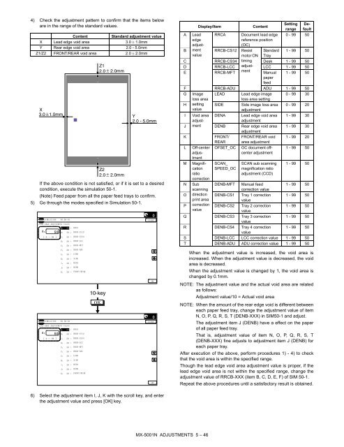
- Page 87: Item Display Content F Image loss a
- Page 91 and 92: NOTE: To execute this adjustment, t
- Page 93 and 94: (Front/rear frame direction image l
- Page 95 and 96: (2) Copy color balance and density
- Page 97 and 98: 4) When [DSPF] button is pressed, i
- Page 99 and 100: c. Adjustment procedure (Auto color
- Page 101 and 102: 6) Check the color balance and dens
- Page 103 and 104: c. Adjustment procedure Copy color
- Page 105 and 106: (Abnormal end (Auto transition))
- Page 107 and 108: • Factory target in the copy colo
- Page 109 and 110: 2) Select the copy mode to be adjus
- Page 111 and 112: Item/Display Density level (Point)
- Page 113 and 114: 20-I Document background density re
- Page 115 and 116: (Adjustment 2) This adjustment is u
- Page 117 and 118: Display/Item (Copy Select Content D
- Page 119 and 120: 2) Select the item A, B with the sc
- Page 121 and 122: Item Button Display Content A OC CO
- Page 123 and 124: 20-T Copy color balance adjustment
- Page 125 and 126: c. Adjustment procedure (Auto color
- Page 127 and 128: 6) Check the color balance and dens
- Page 129 and 130: 1) Enter the SIM 67-25 mode.
- Page 131 and 132: • Relationship between the factor
- Page 133 and 134: 21-C Printer density adjustment (lo
- Page 135 and 136: . Adjustment procedures (Auto color
- Page 137 and 138: 6) Set the color patch image (adjus
- Page 139 and 140:
. Adjustment procedures 1) Enter th
- Page 141 and 142:
1) Go through the modes specified i
- Page 143 and 144:
ADJ 27 Image loss, void area, image
- Page 145 and 146:
6) Press [EXECUTE] key. The f
- Page 147 and 148:
5) After completion of printing, th
- Page 149 and 150:
Standby for entry of SIM sub code E
- Page 151 and 152:
Main Sub Functions Section 23 2 Use
- Page 153 and 154:
Main Sub Functions Section 46 41 Us
- Page 155 and 156:
3. Details of simulation 1 1-1 Purp
- Page 157 and 158:
1 : Oct. 24 2008 3
- Page 159 and 160:
1 : Oct. 24 2008 3-10 Purpose Adjus
- Page 161 and 162:
SIMULATION NO.05-01 5-2 Purpose
- Page 163 and 164:
6-6 Purpose Operation test/check Fu
- Page 165 and 166:
1 1 1 : Oct. 24 2008 8-2 Purpose Op
- Page 167 and 168:
9 9-2 Purpose Operation test/check
- Page 169 and 170:
22 22-1 Purpose Adjustme
- Page 171 and 172:
22-6 Purpose Adjustment/Setting/Ope
- Page 173 and 174:
DRUM DAY K Number of day that used
- Page 175 and 176:
24-2 Purpose Data clear Function (P
- Page 177 and 178:
PRINT BW Print counter (B/W) PRINT
- Page 179 and 180:
26 26-1 Purpose
- Page 181 and 182:
26-10 Purpose Setting Function (Pur
- Page 183 and 184:
(*2) Item B: COLOR MODE set value (
- Page 185 and 186:
Set value Destination Toner prepara
- Page 187 and 188:
Item/Display Content A FSS MODE NEB
- Page 189 and 190:
27-10 Purpose Data clear Function (
- Page 191 and 192:
1 1 : Oct. 24 2008 30 30-1 Purpose
- Page 193 and 194:
1 1 : Oct. 24 2008 41-2 Purpose Adj
- Page 195 and 196:
1 1 : Oct. 24 2008 P HL_UM OHP PAPE
- Page 197 and 198:
1 1 : Oct. 24 2008 [50-sheet machin
- Page 199 and 200:
1 1 : Oct. 24 2008 AB HL_LM E-STAR
- Page 201 and 202:
1 1 : Oct. 24 2008 TH_UM Fusing up
- Page 203 and 204:
1 1 : Oct. 24 2008 [50-sheet machin
- Page 205 and 206:
1 1 1 : Oct. 24 2008 [41-sheet mach
- Page 207 and 208:
1 1 : Oct. 24 2008 Item/Display Con
- Page 209 and 210:
TH_UM Fusing upper thermister main
- Page 211 and 212:
Item/Display Content G PCS_K BELT M
- Page 213 and 214:
Mode Item/Display (*: Correction va
- Page 215 and 216:
44-16 Purpose Operation data displa
- Page 217 and 218:
Category Item/Display Content For p
- Page 219 and 220:
Mode Item/Display Content Setting r
- Page 221 and 222:
1 1 : Oct. 24 2008 Item/Display Con
- Page 223 and 224:
44-61 Purpose Adjustment Function (
- Page 225 and 226:
46-8 Purpose Adjustment (Color scan
- Page 227 and 228:
46-19 Purpose Setting Function (Pur
- Page 229 and 230:
46-26 Purpose Adjustment Function (
- Page 231 and 232:
46-38 Purpose Adjustment/Setup Func
- Page 233 and 234:
Item/Display Content Setting range
- Page 235 and 236:
To check the adjustment density lev
- Page 237 and 238:
46-60 Purpose Adjustment/Setup Func
- Page 239 and 240:
Item/Display Content S MODE0_UNDER
- Page 241 and 242:
1 : Oct. 24 2008 48
- Page 243 and 244:
Item/Display Content FINM Inner fin
- Page 245 and 246:
Item/Display Description C Image lo
- Page 247 and 248:
D Image loss amount setting SIDE1 F
- Page 249 and 250:
50-12 Purpose Adjustment Function (
- Page 251 and 252:
1 1 : Oct. 24 2008 50-22 Purpose Ad
- Page 253 and 254:
Main scanning adjustment error Erro
- Page 255 and 256:
Item classific ation Sampling statu
- Page 257 and 258:
Item classific ation Sampling statu
- Page 259 and 260:
[RSPF] FAX send When image send mod
- Page 261 and 262:
51-2 Purpose Adjustment/Setup Funct
- Page 263 and 264:
1 1 : Oct. 24 2008 Display/Item Con
- Page 265 and 266:
55 55-1 Purpose (Do not use this fu
- Page 267 and 268:
60 60-1 Purpose Operation test/chec
- Page 269 and 270:
1 1 : Oct. 24 2008 Mode Item/Displa
- Page 271 and 272:
62-6 Purpose Operation test/check F
- Page 273 and 274:
[RSPF] Item/ Display Content NOTE G
- Page 275 and 276:
63-8 Purpose Adjustment/Setup Funct
- Page 277 and 278:
64-2 Purpose Operation test/check F
- Page 279 and 280:
64-5 Purpose Operation test/check F
- Page 281 and 282:
64-7 Purpose Operation test/check F
- Page 283 and 284:
67-26 Purpose Adjustment/Setup Func
- Page 285 and 286:
67-34 Purpose Adjustment/Setup Func
- Page 287 and 288:
[7] SELF DIAG AND TROUBLE MX-5001N
- Page 289 and 290:
Kind of trouble General PCU color s
- Page 291 and 292:
1 1 : Oct. 24 2008 Trouble code Mai
- Page 293 and 294:
Trouble code Main code Sub code U6
- Page 295 and 296:
E7-08 MFP memory compatibility erro
- Page 297 and 298:
E7-80 MFP-SCU PWB communication err
- Page 299 and 300:
F1-32 Finisher - Punch unit communi
- Page 301 and 302:
1 : Oct. 24 2008 F2-41 Toner densit
- Page 303 and 304:
F2-72 Improper toner cartridge dete
- Page 305 and 306:
H3-04 Fusing section high temperatu
- Page 307 and 308:
H7-14 Recovery error from low fuser
- Page 309 and 310:
L4-45 Toner cooling fan trouble (To
- Page 311 and 312:
U2-24 MFP PWB SRAM memory user auth
- Page 313 and 314:
U6-09 LCC lift trouble Trouble cont
- Page 315 and 316:
A0-21 Conflict firmware and EEPROM
- Page 317 and 318:
Fusing section (Others) Part name L
- Page 319 and 320:
2. Details A. Photoconductor sectio
- Page 321 and 322:
4) Insert the MC cleaner rod into t
- Page 323 and 324:
16) Remove the side seal F/R. Maint
- Page 325 and 326:
(Note for servicing the DV roller)
- Page 327 and 328:
11) Remove the DV side seal F/R. Ma
- Page 329 and 330:
D. LSU section ✕: Check (Clean, r
- Page 331 and 332:
E. Transfer section ✕: Check (Cle
- Page 333 and 334:
(Note for servicing the transfer un
- Page 335 and 336:
10) Remove the screws, and remove t
- Page 337 and 338:
22) Remove the secondary belt trans
- Page 339 and 340:
19 18 17 15 (1) Fusing paper exit r
- Page 341 and 342:
2) Remove the web roller (on the wi
- Page 343 and 344:
4) Remove the screw, disconnect the
- Page 345 and 346:
3) Disengage the hook of the lower
- Page 347 and 348:
1 : Oct. 24 2008 NOTE: When install
- Page 349 and 350:
H. Paper feed section ✕: Check (C
- Page 351 and 352:
I. Paper transport section ✕: Che
- Page 353 and 354:
1) Clean the paper exit roller 2 (D
- Page 355 and 356:
L. Scanner section ✕: Check (Clea
- Page 357 and 358:
1) Open the paper feed unit. 2) Rem
- Page 359 and 360:
1) Open the upper door. Remove the
- Page 361 and 362:
16) Remove the connector from the D
- Page 363 and 364:
3. Maintenance and disassembly A. M
- Page 365 and 366:
(1) Firmware update procedure from
- Page 367 and 368:
D. Emergency update (incase of an H
- Page 369 and 370:
1 1 : Oct. 24 2008 (2) MX-4100N/500
- Page 371 and 372:
C. PCU PWB (1) MX-4101N/4100N FAN P
- Page 373 and 374:
D. Scanner control PWB INV PWB 8.5
- Page 375 and 376:
F. Serial communication RxD[1] P.U.
- Page 377 and 378:
1 1 : Oct. 24 2008 (2) MX-5001N/500
- Page 379 and 380:
1 1 : Oct. 24 2008 (2) MX-5001N/500
- Page 381 and 382:
1 1 : Oct. 24 2008 J. DC power line
- Page 383 and 384:
(2) DSPF CNT PWB section 2/2 SPPD2
- Page 385 and 386:
B. RSPF 179228-3(BLACK) RSPF DRIVER
- Page 387 and 388:
(2) Front section (P2) INTCNT DSW-R
- Page 389 and 390:
1 1 : Oct. 24 2008 b. Fusing unit s
- Page 391 and 392:
(5) Process drive unit section 1/2
- Page 393 and 394:
(7) DL and DV section (P7) PCU PWB
- Page 395 and 396:
(9) Paper feed unit section (P9) PH
- Page 397 and 398:
(11) PS unit and Process control un
- Page 399 and 400:
(13) Paper exit unit section (P13)
- Page 401 and 402:
(15) DESK and LCC (P15) (DC main ha
- Page 403 and 404:
MX-5001N ELECTRICAL SECTION 10 - 36
- Page 405 and 406:
(19) FAX section (P19) MFP PWB CN18
- Page 407 and 408:
(21) USB section (P21) KEY PWB SRA-
- Page 409 and 410:
Signal name CSS12 Tray 1 paper size
- Page 411 and 412:
Signal name POFM_ LD2 Name [Type] F
- Page 413 and 414:
[11] OTHERS MX-5001N Item 1. Syst
- Page 415 and 416:
Item Factory default setting Setti
- Page 417 and 418:
Item Factory default setting ◆ Le
- Page 419 and 420:
3. MFP substrate replacement proced
- Page 421 and 422:
(4) Upper cabinet right/Upper cabin
- Page 423 and 424:
MX-5001N [B] OPERATION PANEL 1. El
- Page 425 and 426:
3) Remove the screw, remove the ear
- Page 427 and 428:
MX-5001N [C] DSPF SECTION 1. Elect
- Page 429 and 430:
D. Optical section E. Peper exit se
- Page 431 and 432:
3. Disassembly and assembly A. DSPF
- Page 433 and 434:
1) Remove the front cabinet. 2) Rem
- Page 435 and 436:
(3) DSPF No.2 resist roller clutch
- Page 437 and 438:
(1) DSPF transport motor 1) Remove
- Page 439 and 440:
MX-5001N [D] RSPF SECTION 1. Elect
- Page 441 and 442:
B. Paper feed transport operation (
- Page 443 and 444:
11) Resist operation (First sheet b
- Page 445 and 446:
7) Stop at the stamping position/St
- Page 447 and 448:
(1) SPF document with sensor 1) Rem
- Page 449 and 450:
D. Reversing section Parts a Docume
- Page 451 and 452:
MX-5001N [E] SCANNER SECTION 1. El
- Page 453 and 454:
3. Disassembly and assembly A. Scan
- Page 455 and 456:
(5) Document detection light emitti
- Page 457 and 458:
Signal name Name Function/Operation
- Page 459 and 460:
Signal name Name Function/Operation
- Page 461 and 462:
3) Remove the lock block. Disengage
- Page 463 and 464:
6) Remove the MF upper base paper g
- Page 465 and 466:
MX-5001N [G] PAPER TRANSPORT SECTIO
- Page 467 and 468:
MX-5001N [H] LSU SECTION 1. Electr
- Page 469 and 470:
1 : Oct. 24 2008 (Writing position
- Page 471 and 472:
B. Others Parts a LSU shutter solen
- Page 473 and 474:
Signal name Name Function/Operation
- Page 475 and 476:
1 1 : Oct. 24 2008 Signal name Name
- Page 477 and 478:
5) Pinch the knob and remove the de
- Page 479 and 480:
2. Operational descriptions When th
- Page 481 and 482:
Signal name Name Function/Operation
- Page 483 and 484:
MX-5001N [L] TRANSFER SECTION 1. E
- Page 485 and 486:
2. Operational descriptions A. Tran
- Page 487 and 488:
5) Hold the specified position, and
- Page 489 and 490:
Signal name Name Function/Operation
- Page 491 and 492:
(1) Upper thermostat 1) Remove the
- Page 493 and 494:
1 : Oct. 24 2008 NOTE: When install
- Page 495 and 496:
Signal name Name Function/Operation
- Page 497 and 498:
2. Operational descriptions A. Dupl
- Page 499 and 500:
B. Paper exit unit c Unit Parts (1)
- Page 501 and 502:
1 1 1 : Oct. 24 2008 [O] DRIVE SECT
- Page 503 and 504:
1 1 1 1 : Oct. 24 2008 (7) C drum m
- Page 505 and 506:
5) Disconnect the connector, and re
- Page 507 and 508:
[P] PWB SECTION MX-5001N A. Contr
- Page 509 and 510:
c) Raise the memory PWB until the c
- Page 511 and 512:
3) Remove the screw and disconnect
- Page 513 and 514:
(6) Primary transfer PWB 1) Remove
- Page 515 and 516:
4) Disconnect the connector and rem
- Page 517 and 518:
[R] SENSOR/SWITCH SECTION MX-5001N
- Page 519 and 520:
Memo
- Page 521 and 522:
Memo
- Page 523 and 524:
CAUTION FOR BATTERY REPLACEMENT (Da