


Create successful ePaper yourself
Turn your PDF publications into a flip-book with our unique Google optimized e-Paper software.
FUNCTION OF TOOL FEATURES FOR TURNING<br />
<strong>TECHNICAL</strong><br />
<strong>DATA</strong><br />
G014<br />
<strong>TECHNICAL</strong> <strong>DATA</strong><br />
FUNCTION OF TOOL FEATURES<br />
FOR TURNING<br />
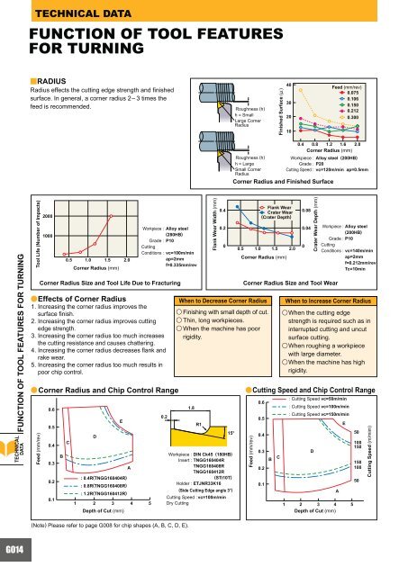
yRADIUS<br />
Radius effects the cutting edge strength and finished<br />
surface. In general, a corner radius 2– 3 times the<br />
feed is recommended.<br />
Tool Life (Number of Impacts)<br />
2000<br />
1000<br />
0.6<br />
0.5<br />
0.4<br />
0.3<br />
0.2<br />
0.1<br />
B<br />
0.5 1.0 1.5 2.0<br />
aEffects<br />
of Corner Radius<br />
1. Increasing the corner radius improves the<br />
surface finish.<br />
2. Increasing the corner radius improves cutting<br />
edge strength.<br />
3. Increasing the corner radius too much increases<br />
the cutting resistance and causes chattering.<br />
4. Increasing the corner radius decreases flank and<br />
rake wear.<br />
5. Increasing the corner radius too much results in<br />
poor chip control.<br />
C<br />
Corner Radius (mm)<br />
D<br />
: 0.4R(TNGG160404R)<br />
: 0.8R(TNGG160408R)<br />
: 1.2R(TNGG160412R)<br />
1 2 3 4 5<br />
E<br />
A<br />
Workpiece :<br />
Grade :<br />
Cutting<br />
Conditions :<br />
0.2<br />
Alloy steel<br />
(280HB)<br />
P10<br />
Corner Radius Size and Tool Life Due to Fracturing<br />
vc=100m/min<br />
ap=2mm<br />
f=0.335mm/rev<br />
1.8<br />
R1<br />
40<br />
30<br />
20<br />
10<br />
Flank Wear<br />
0.4<br />
Crater Wear<br />
0.08<br />
(Crater Depth)<br />
0.2<br />
Workpiece : DIN Ck45 (180HB)<br />
Insert : TNGG160404R<br />
TNGG160408R<br />
TNGG160412R<br />
(STi10T)<br />
Holder : ETJNR33K16<br />
0<br />
15°<br />
Roughness (h)<br />
h = Small<br />
Large Corner<br />
Radius<br />
Roughness (h)<br />
h = Large<br />
Small Corner<br />
Radius<br />
0.5 1.0 1.5 2.0<br />
Corner Radius (mm)<br />
0.6<br />
0.5<br />
0.4<br />
0.3<br />
0.2<br />
0.1<br />
B C<br />
Feed (mm/rev)<br />
0.075<br />
0.106<br />
0.150<br />
0.212<br />
0.300<br />
0.4 0.8 1.2 1.6 2.0<br />
Corner Radius (mm)<br />
Corner Radius and Finished Surface<br />
aCorner Radius and Chip Control Range<br />
aCutting<br />
Speed and Chip Control Range<br />
Feed (mm/rev)<br />
Depth of Cut (mm)<br />
(Note) Please refer to page G008 for chip shapes (A, B, C, D, E).<br />
Flank Wear Width (mm)<br />
When to Decrease Corner Radius<br />
u Finishing with small depth of cut.<br />
u Thin, long workpieces.<br />
u When the machine has poor<br />
rigidity.<br />
(Side Cutting Edge angle 3°)<br />
Cutting Speed : vc=100m/min<br />
Dry Cutting<br />
Finished Surface (!)<br />
Workpiece : Alloy steel (200HB)<br />
Grade : P20<br />
Cutting Speed : vc=120m/min ap=0.5mm<br />
0.04<br />
0<br />
Crater Wear Depth (mm)<br />
Corner Radius Size and Tool Wear<br />
Feed (mm/rev)<br />
D<br />
Workpiece : Alloy steel<br />
(200HB)<br />
Grade : P10<br />
Cutting<br />
Conditions : vc=140m/min<br />
ap=2mm<br />
f=0.212mm/rev<br />
Tc=10min<br />
When to Increase Corner Radius<br />
uWhen<br />
the cutting edge<br />
strength is required such as in<br />
interrupted cutting and uncut<br />
surface cutting.<br />
uWhen<br />
roughing a workpiece<br />
with large diameter.<br />
uWhen<br />
the machine has high<br />
rigidity.<br />
: Cutting Speed vc=50m/min<br />
: Cutting Speed vc=100m/min<br />
: Cutting Speed vc=150m/min<br />
1 2 3 4 5<br />
Depth of Cut (mm)<br />
A<br />
E<br />
50<br />
100<br />
150<br />
150<br />
100<br />
50<br />
Cutting Speed (m/mim)