I/Q Vectors Swap

Create successful ePaper yourself
Turn your PDF publications into a flip-book with our unique Google optimized e-Paper software.
FEATURE Phase Shifts in Digital TV<br />
I/Q<br />
<strong>Vectors</strong><br />
<strong>Swap</strong><br />
• how to detect phase shifts automatically<br />
• reversing inverted phase shifts<br />
• finding the synchronization byte<br />
• how a constellation diagram shows<br />
swapped vectors<br />
140 TELE-audiovision International — The World‘s Largest Digital TV Trade Magazine — 03-04/2013 — www.TELE-audiovision.com www.TELE-audiovision.com — 03-04/2013 — TELE-audiovision International — 全球发行量最大的数字电视杂志 141
FEATURE Phase Shifts in Digital TV<br />
Jacek<br />
As satellite signal analyzers become more and more<br />
affordable, many satellite enthusiasts decide to buy<br />
and use them. When they start playing with their new<br />
instruments, they sometimes encounter terms not so<br />
obvious to everybody. Transponder frequency, symbol<br />
rate, FEC or polarization are commonly used and most<br />
of the users have no problem in apprehending their<br />
meaning. But I/Q vectors can be a puzzle for some of<br />
the fans. You can see “I/Q Normal” and “I/Q Inverted”<br />
(or “I/Q <strong>Swap</strong>ped”) options in some analyzer screens.<br />
What does it mean? In fact, it is not anything complex<br />
and we will explain it in a simple way in this feature<br />
article.<br />
Let’s consider the simplest<br />
form of modulation used in<br />
satellite TV – QPSK. In this<br />
modulation, the sinusoidal<br />
signal amplitude remains<br />
unchanged but its phase can<br />
change at regular intervals.<br />
For example, if we have a<br />
transponder broadcasting<br />
with a symbol rate of 27.5<br />
Ms/sec, its phase can change<br />
27.5 million times in a second.<br />
Or we can say that one<br />
symbol lasts for<br />
sec (about 36 nanoseconds).<br />
There are four phase shifts<br />
allowed in QPSK what cor-<br />
142 TELE-audiovision International — The World‘s Largest Digital TV Trade Magazine — 03-04/2013 — www.TELE-audiovision.com<br />
Phase<br />
shift<br />
Symbol<br />
45° 00<br />
135° 01<br />
225° 11<br />
315° 10<br />
responds to four different<br />
symbols.<br />
In the figures below<br />
(graph.1-3), you can see an<br />
example of a QPSK modulated<br />
carrier with all four possible<br />
phase shifts in the order:<br />
45°, 135°, 225°, 315°.<br />
In this example, there are<br />
■graph 1.<br />
■graph 2.<br />
■graph 3.
four symbols sent: 00, 01, 11<br />
and 10. Just to remind you,<br />
in QPSK, a symbol is a pair<br />
of subsequent bits.<br />
Phase shifts are produced<br />
by summing a carrier signal<br />
with the auxiliary signal<br />
of the same frequency but<br />
shifted in phase by 90°. A<br />
QPSK modulated signal can<br />
be defined as:<br />
The resulting y(t) is also a<br />
sine function but its amplitude<br />
and phase depends on<br />
the I and Q values. In QPSK<br />
modulation I and Q can be<br />
equal either to 1 or to -1.<br />
Therefore we have four different<br />
possibilities for y(t):<br />
or<br />
or<br />
or<br />
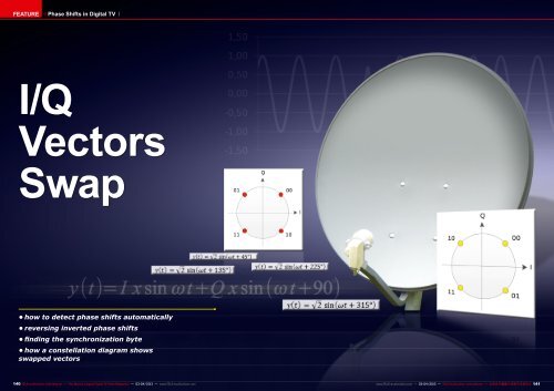
A pair of bits is assigned<br />
to each possible state of<br />
y(t) in QPSK. This is shown<br />
graphically in a constellation.<br />
(graph 4.)<br />
In other words, if the in-<br />
coming signal is shifted 45°<br />
in phase,<br />
your receiver understands<br />
that two zero bits are being<br />
sent to it. If the signal is<br />
shifted by 135°, your box assumes<br />
that bits 1 and 0 have<br />
arrived and so on.<br />
And what will happen if we<br />
swap the I and Q vectors?<br />
This may happen if somebody<br />
unintentionally sets<br />
up the headend in a wrong<br />
way or simply will not take<br />
into account the natural vector<br />
swap that takes place<br />
in some frequency conversions.<br />
In such situation the constellation<br />
will look differently<br />
– see the graph 5.<br />
The 45° and 225° shifts<br />
produce the same bits as<br />
previously but the remaining<br />
two: 135° and 315° are<br />
swapped.<br />
So, in a continuous flow of<br />
bits, some pairs of bits will<br />
stay undistorted (00 and<br />
11) but the other pairs will<br />
take reverse values 10 will<br />
change to 01 and vice versa.<br />
That’s the effect of inverted<br />
I/Q modulation.<br />
■graph 4. ■graph 5.<br />
144 TELE-audiovision International — The World‘s Largest Digital TV Trade Magazine — 03-04/2013 — www.TELE-audiovision.com<br />
,<br />
Some old timers can still<br />
remember the first generation<br />
of satellite receivers that<br />
in their transponder data required<br />
the user to define I/Q<br />
Normal or I/Q Inverted. More<br />
recent receiver can automatically<br />
detect I/Q inversion<br />
and reverse the operation of<br />
their demodulators accordingly.<br />
But how is it possible to<br />
detect a I/Q swap?<br />
The transport stream consists<br />
of fixed length data<br />
packets. For example the<br />
DVB standard requires the<br />
packet to have 204 bytes.<br />
The very first byte in every<br />
packet is always the same<br />
0x47 in hexadecimal notation<br />
or simply 01000111 in<br />
binary format. It is called<br />
the sync byte as it is used<br />
for synchronization. Your receiver<br />
right after tuning to a<br />
new transponder starts looking<br />
for the 0x47 bytes to find<br />
the ones located every 204<br />
bytes in a stream. Only in<br />
this way it can start decoding<br />
the content of the packets.<br />
If it is impossible to find<br />
regularly spaced 0x47 bytes,<br />
it is a clear indication that<br />
I/Q vectors are swapped. So,<br />
the receiver also swaps I/Q<br />
signals in its demodulator<br />
because one inversion and<br />
another inversion recreates<br />
the normally modulated signal<br />
again.<br />
The principle described<br />
above applies also to more<br />
complex modulations like<br />
8PSK or QAM. The only difference<br />
is that I and Q can<br />
take more values than 1<br />
and -1 as in QPSK what results<br />
in more phase shifts<br />
and amplitude values of y(t).<br />
The effect of I/Q swap is<br />
the same: some bits remain<br />
unchanged, the others are<br />
reversed (0 becomes 1 and<br />
vice versa). However, as you<br />
already know now, it is not<br />
so difficult to detect such<br />
situation and take countermeasures<br />
- simply apply<br />
additional I/Q swaps in a receiver.<br />
Signal analyzer can detect<br />
I/Q swap on the same basis<br />
as your receiver does. QPSK<br />
modulators usually offer in<br />
their menu a possibility to<br />
invert I and Q vectors. Today,<br />
it does not make any<br />
difference to your receiver<br />
whether a transponder<br />
transmits with normal or inverted<br />
I/Q vectors. And the<br />
viewer cannot sense it in any<br />
way either.