SEATTLE'S SEISMIC RETROFIT PROGRAM David W. Korpi1 ...
SEATTLE'S SEISMIC RETROFIT PROGRAM David W. Korpi1 ...
SEATTLE'S SEISMIC RETROFIT PROGRAM David W. Korpi1 ...

You also want an ePaper? Increase the reach of your titles
YUMPU automatically turns print PDFs into web optimized ePapers that Google loves.
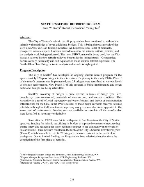
SEATTLE’S <strong>SEISMIC</strong> <strong>RETROFIT</strong> <strong>PROGRAM</strong><br />
<strong>David</strong> W. Korpi 1 ; Robert Richardson 2 ; Yuling Teo 3<br />
Abstract<br />
The City of Seattle’s seismic retrofit program has been continued to address the<br />
seismic vulnerabilities of seven additional bridges. This is being done as a result of the<br />
City’s Bridging the Gap funding initiative. An Expert Review Panel of nationally<br />
recognized seismic experts has been formed to review the seismic criteria, policies, and<br />
the analysis work being performed. The latest FHWA manual is being used, but the City<br />
has also tailored its own retrofit policy to best utilize its limited funds. Geotechnical<br />
hazards of high seismicity and soil liquefaction make seismic retrofit expedient. The<br />
South Albro Place Bridge seismic analysis and retrofit is highlighted.<br />
Program Description<br />
The City of Seattle 4 has developed an ongoing seismic retrofit program for the<br />
approximately 120-plus bridges in their inventory. Beginning in the early 1990s, Phase I<br />
of the retrofit program was implemented, and 23 bridges were retrofitted to various levels<br />
of seismic performance. Now Phase II of this program is being implemented and seven<br />
additional bridges are being retrofitted.<br />
Seattle’s inventory of bridges is quite diverse in terms of bridge type, size,<br />
complexity, date constructed, materials of construction, and current condition. This<br />
variability is a result of local topography and water features, and layout of transportation<br />
infrastructure for the City. In the 1990’s several of these major corridors received seismic<br />
retrofits, although not all structures comprising any given corridor were upgraded to the<br />
same level of performance. Funding was not available to complete all the retrofits that<br />
were identified as necessary or desirable.<br />
Soon after the 1989 Loma Prieta earthquake in San Francisco, the City of Seattle<br />
approved funding for seismic retrofitting its bridges as a proactive measure in protecting<br />
public safety and reducing the socio-economic impact to the community in the event of<br />
an earthquake. This measure resulted in the birth of the City’s Seismic Retrofit Program<br />
(Phase I) which was able to retrofit 23 bridges to be more resistant in the event of an<br />
earthquake. Due to limited funding, the Program has been relatively inactive since the<br />
completion of the first phase of retrofits.<br />
1 Senior Project Manager, Bridge and Structures, HDR Engineering, Bellevue, WA<br />
2 Project Manager, Bridge and Structures, HDR Engineering, Bellevue, WA<br />
3 Supervising Structural Engineer, Seattle Department of Transportation, Seattle, WA<br />
4 Hereinafter “Seattle”, “City”, and “SDOT” are synonymous.<br />
231
In 2006, Seattle voters passed a nine-year, $365 million levy for transportation<br />
maintenance and improvements known as Bridging the Gap. The levy was complemented<br />
by a commercial parking tax ($127.5 million) and an employee hour’s tax ($51.5<br />
million). Over life of the levy the total expected revenue from the three sources is $544<br />
million. In the nine-year period which began January 2007, the Bridging the Gap funds<br />
will be available for transportation capital projects and the much needed infrastructure<br />
maintenance. This work to be funded through Bridging the Gap includes the following:<br />
• Paving and repairing streets<br />
• Constructing and improving sidewalks<br />
• Rehabilitating roadway structures including bridges, retaining walls, and<br />
stairways<br />
• Bridge seismic retrofitting<br />
• Improving major corridors<br />
As a result of this renewed emphasis and Bridging the Gap funding, the City<br />
decided to reactivate the Seismic Retrofit Program, and the following bridges were<br />
designated for Phase II:<br />
1. Fauntleroy Expressway<br />
2. Ballard Bridge<br />
3. King St. Station Vicinity Bridges (includes four structures)<br />
4. South Albro Place<br />
Expert Review Panel<br />
One of the successes of Phase I of the retrofit program was the utilization of a<br />
review panel of noted seismic experts. They reviewed the criteria, seismic analysis,<br />
strategies, and proposed retrofits. Phase I of the retrofit program was based upon the<br />
FHWA 1995 manual (Ref. 5). Since this approach was relatively new and untested, the<br />
City determined it was expedient to have the panel of experts involved in the Phase I of<br />
the program from the beginning.<br />
For the same reasons, and because it was so successful in Phase I, the City has<br />
elected to gather a panel of experts to review the Phase II program work. For a list of<br />
seismic experts on the Expert Review Panel (ERP), see the Acknowledgements.<br />
Specific bridge seismic retrofit design criteria were developed for the program<br />
based upon the bridge seismic retrofit philosophies and policies established by the City.<br />
These criteria encompass current state of the art technology on the seismic retrofit of<br />
bridges, and have been reviewed by the Expert Review Panel (ERP). The Bridge Seismic<br />
Retrofit Criteria addressed technical, financial, functional, physical, and community<br />
parameters/considerations.<br />
232
Seismic Retrofit Philosophy<br />
The philosophy of the SDOT Bridge Seismic Retrofit Program is comprised of<br />
two guiding principles:<br />
1) First and foremost, provide for public safety in the event of an earthquake<br />
2) Reduce the socio-economic impact of an earthquake to the community to a<br />
reasonable extent<br />
This philosophy led to the establishment of appropriate retrofit criteria. In keeping<br />
with the philosophy for new bridge design (Ref. 2), the following general performance<br />
objectives of the retrofit program were identified:<br />
• Small to moderate earthquakes should be resisted within the elastic range,<br />
without significant damage<br />
• Realistic seismic ground motion intensities and forces should be used in the<br />
design procedures<br />
• Exposure to shaking from large earthquakes should not cause collapse of all or<br />
part of the bridge. Where possible, damage that does occur should be readily<br />
detectable and accessible for inspection and repair.<br />
SDOT Retrofit Policies<br />
The most recent seismic retrofit guidelines published by FHWA and MCEER<br />
(Ref. 3) are based on a two-level approach, whereby for standard bridges operational<br />
performance is desired for a smaller, more frequent earthquake and life-safety/no collapse<br />
performance is desired in a larger event. While this is ideal, limited public funds has led<br />
the City to make prevention of loss of life the paramount concern over bridge operations.<br />
The reason for this is to improve the greatest portion of the bridge inventory with the<br />
monies available. This observation is noted in the new LRFD provisions for seismic<br />
design (Ref. 1), including the Guide Specification for new design (Ref. 2), where a single<br />
level earthquake is used for design of new structures; no service level earthquake is<br />
mandatory for consideration. Thus, a lower service level of earthquake was evaluated, but<br />
based on costs, retrofitting for a lower level earthquake was considered optional.<br />
The following policies have been adopted by the City for their retrofit program:<br />
• Bridge Importance - All City bridges will be considered “Standard”.<br />
• Earthquake Hazard Levels and Performance - A 1000-year return period (Upper<br />
Level Earthquake) was used to design seismic retrofits to prevent collapse and<br />
threats to life safety. A 100-year return period (Lower Level Earthquake) was<br />
used to design retrofits to maintain operations after more frequent events.<br />
• Remaining Service Life - A bridge that has 15 years or less of remaining service<br />
life, or is scheduled for replacement within the next 15 years, will be considered<br />
by SDOT on a case-by-case basis for retrofit. Each bridge will be considered by<br />
233
SDOT based on its own vulnerabilities, importance and likelihood of future<br />
replacement. Additionally, if inexpensive retrofit measures, for example<br />
restrainers, provide significant enhancement to life safety, then such retrofits may<br />
be considered.<br />
• Age of Bridge - Bridges built after 1983 and were designed with the AASHTO<br />
1983 Guide Specification or later versions will not be considered as high priorities<br />
for retrofit.<br />
• Bridge Location / Usage - Small neighborhood bridges or pedestrian bridges over<br />
minor, non-lifeline roadways will not be retrofitted.<br />
• Holistic Retrofit Approach - The City will not adopt the phased approach to<br />
retrofitting but rather will develop a complete list of retrofit needs for a given<br />
bridge.<br />
• Performance-Based Retrofit - The City will adopt a performance-based seismic<br />
retrofit approach for its bridges. To the extent possible, more advanced<br />
displacement-based assessment techniques, such as pushover (nonlinear static)<br />
analysis, should be used as a minimum.<br />
• Seismic Retrofits For Bridge Preservation - Seismic retrofit is viewed as a bridge<br />
preservation strategy by SDOT, and not a general transportation improvement<br />
strategy; thus, under this Program only the bridge features that require retrofitting<br />
to satisfy seismic performance objectives will be constructed.<br />
• Bridges Previously Retrofitted - Bridges that were retrofitted in previous phases<br />
to either operational or life safety levels, and for which all identified retrofits were<br />
constructed, will not be retrofitted further.<br />
• Subsurface Foundation Retrofit - Investing in subsurface retrofit will be a low<br />
priority unless the life-safety performance level cannot be met without such<br />
retrofit.<br />
• Retrofit vs. Replacement Cost Considerations - If cost of retrofit is a substantial<br />
fraction of the replacement cost for a given bridge, SDOT may choose not to<br />
retrofit and instead program the bridge for replacement.<br />
• Liquefaction - The potential for liquefaction and liquefaction-induced hazards,<br />
such as lateral spreading, will be identified in the geotechnical report. The effect<br />
of liquefaction on lateral resistance and vertical support of the structure will be<br />
considered.<br />
Geotechnical Issues<br />
High Seismicity<br />
Seattle’s geology and geomorphology are as varied as its bridge inventory.<br />
Geotechnical parameters range from sandstone to soft, lake clay with peat deposits. In<br />
some instances soil characteristics vary significantly from one end of a bridge to the<br />
234
other. This requires a greater modeling complexity in order to determine appropriate soil<br />
response under dynamic loading. In most cases, we utilized an enveloping procedure in<br />
an effort to capture the effects of this soil variance in our assessments of foundation<br />
stability and overall structure deformation.<br />
Seattle’s bridge inventory is located within the Seattle Fault Zone, a relatively<br />
high seismic zone. Peak ground accelerations for the upper level earthquake range from<br />
0.43g to 0.47g. According to Geotechnical Reports, the recurrence interval for large<br />
earthquakes with large ground surface deformation in the Seattle Fault Zone is on the<br />
order of 3,000 to 5,000 years. This is much longer than the return periods of the upper<br />
and lower ground level motions (100- and 1,000 years). As such, the risk posed by faultinduced<br />
ground surface rupture for the ground motion hazard level has been categorized<br />
as low to moderate. None of the bridges initially selected for investigation span currently<br />
mapped splays, so near-fault effects were considered on a qualitative basis only.<br />
Liquefaction<br />
Liquefaction induced settlement has been identified with a high probability at all<br />
of the bridge locations. However, since the vast majority of bridge foundations in these<br />
areas are supported by piles, the risk of collapse due to this form of settlement is<br />
considered low. The greater risk is posed by the deteriorated lateral support of the piles<br />
during liquefaction.<br />
The terrain at the majority of the selected bridge sites is relatively flat, for the<br />
most part. In most cases the risk of lateral spread has been categorized as low, with the<br />
exception of specific locations adjacent to the Fauntleroy Expressway.<br />
Project Highlight - South Albro Place Bridge<br />
The South Albro Place bridge spans over Airport Way South and BNSF and<br />
UPRR railroad tracks and connects Stanley Avenue South with Swift Avenue South in<br />
the area commonly referred to as Georgetown, just north of Boeing Field and west of I-5.<br />
The bridge was originally constructed in 1931. (See Figure 2 and Photo 4).<br />
Overall bridge length is approximately 172-meters, measured between abutments.<br />
The bridge consists of three frame units separated by expansion joints and Bents 3 and 6.<br />
Unit 1 superstructure, from Abutment 1 to Bent 3, is comprised of reinforced concrete<br />
slab spans with drop-cap bent caps at Bents 1 and 2. The other two units’ superstructures<br />
consist of reinforced concrete haunch girders with standard bridge deck. Each span has<br />
three girders of varying depths, depending on adjacent span lengths.<br />
All bents are supported on timber piles. Bents 1 and 2 are two-column bents, with<br />
rectangular reinforced concrete column supported atop a truncated pyramid plinth that<br />
extends down to the reinforced concrete pile cap. Bent 3 consists of three reinforced<br />
concrete columns, with concrete counterforts. Bents 4 through 10 are all three column<br />
bents. There are three reinforced concrete struts spanning between columns located at the<br />
top of the plinth, mid-height, and at the capital. Bent 10 was similar to bents 4 through 9<br />
except for the absence of the middle concrete strut.<br />
235
The tops of the columns of Bents 1 and 2 are integrally connected to the<br />
superstructure. Each column of Bent 3 is connected to the bridge girders by means of a<br />
mechanical pin-bearing assembly. At Bents 4 thru 10, the top of each column terminates<br />
with a rocker bearing assembly embedded inside the trapezoidal concrete capital. Grout<br />
was placed around the perimeter of the capital to nearly fill the space between the<br />
reinforced concrete capital and the bridge girder.<br />
The bridge appears to be in generally fair condition with minor, localized concrete<br />
spalls and some cracking.<br />
Displacement Demand Analysis<br />
There were four distinct structural models associated with the as-built analysis of<br />
South Albro Place Bridge. The “compression model” consisted of the entire bridge<br />
modeled together assuming that the expansion joints at Bents 3 and 6 have closed.<br />
Additionally, there were three independent frame “tension” models that were established<br />
to determine the expected displacements in the event that an adjacent frame was not there<br />
to provide restraint. The demands from the respective models were compared for each<br />
bent and the largest value in each instance was used to determine the transverse and<br />
longitudinal displacement demands.<br />
FWHA guidelines (Ref. 4) were followed to provide initial soil springs for items<br />
such as abutment backwalls, and pile footing springs, etc. The overall structural model<br />
was then run with these initial springs. Abutment backwall springs were developed by<br />
iterating until the combined longitudinal force at both abutments was less than or equal to<br />
the expected soil passive resistance at only one end, since only one end of the bridge was<br />
compressing soil at any given time. Additionally, the longitudinal displacement was<br />
checked to assure that the gap between abutment backwall and superstructure was closed<br />
and that the soil had been engaged. Transversely, the abutment forces were checked<br />
against the footing’s sliding resistance.<br />
Pile footing stiffnesses were iterated using WSDOT’S DFSAP program so that<br />
the forces applied to the foundations and resulting displacements and rotations<br />
determined from the SAP2000 analysis matched up with those used in the DFSAP model.<br />
Seismic demands were determined from a multi-modal response spectrum<br />
analysis using SAP2000 v.11. (See Figure 3) A sufficient number of modes were<br />
included to account for at least 90-percent participation of the total mass. Modal<br />
response contributions were combined using the CQC method. Response of the structure<br />
was analyzed in two orthogonal horizontal directions and the results were combined<br />
according to the SRSS rule. Vertical acceleration effects were not included in this<br />
analysis.<br />
The following assumptions were made for all response spectrum models:<br />
1. Members were modeled with frame elements with 6 degrees of freedom at<br />
each joint.<br />
236
2. The superstructure was modeled as a spine with 10 equal segments per<br />
span. Superstructure frame elements were modeled at the composite neutral<br />
axis.<br />
3. End pier foundation stiffness was modeled with equivalent springs. Passive<br />
pressure was included on the end pier backwall in accordance with §6.2.2.4<br />
of the FHWA Manual (Ref. 4).<br />
4. Interior piers were modeled as a frame with each column connected to a<br />
rigid crossbeam. Column-to-crossbeam joint regions were modeled with<br />
rigid links. A rigid link was also used to connect the crossbeam to the<br />
superstructure. Piers were skewed from the superstructure spine to the<br />
angles shown on the as-built drawings.<br />
5. Columns were modeled with equivalent cracked stiffness. The reduced<br />
stiffness values were determined using methods provided in the FHWA<br />
Manual §7.3.2.1.<br />
6. Interior pier foundation stiffness was modeled with equivalent 6 x 6<br />
springs at each footing in accordance with WSDOT BDM (Ref. 9). Pile<br />
foundations springs were generated using DFSAP. Spread footing springs<br />
were generated by the Half-space Method, utilizing the formulas presented<br />
in Section 6.2.2.1(b) of the FHWA Manual.<br />
7. Mass was distributed in accordance with §7.3.1 of the FHWA Manual. The<br />
inertia of live loads was not included.<br />
8. A constant 5-percent damping coefficient was used for all modes.<br />
Displacement Capacity Analysis<br />
Albro Place Bridge was analyzed utilizing a Method D2 evaluation. The seismic<br />
displacement capacity using non-linear static push-over analysis in SAP2000 v.11 was<br />
determined from the following procedures:<br />
• The un-factored dead load DC and DW were applied to the model as an initial<br />
step. The resulting system displacement from the un-factored DC and DW<br />
loading was the non-seismic displacement demand.<br />
• Incremental lateral forces were applied to the system. A plastic hinge was<br />
assumed to form at either the top or bottom of column and was formed when the<br />
internal moments reach the idealized plastic moment capacity. Plastic hinging of<br />
existing struts was permitted, however the struts were modeled with infinite<br />
strength. The sequence of plastic hinging through the system was tracked until an<br />
ultimate failure (collapse mechanism) was reached. The difference between the<br />
system displacement at collapse and the non-seismic displacement demand was<br />
the seismic displacement capacity.<br />
• Separate pushover models were used to determine the longitudinal and transverse<br />
seismic displacement capacity. The response spectrum bridge model was<br />
237
modified to include plastic hinges at the top and bottom of each bent column. The<br />
model was then pushed in the longitudinal (parallel to centerline of structure)<br />
direction to determine the longitudinal seismic displacement capacity. Each bent<br />
was also modeled as a stand-alone frame model and pushed in the transverse<br />
(normal to centerline of bridge) direction to determine the transverse seismic<br />
displacement capacity.<br />
• Mander's unconfined and confined concrete models (Ref. 6) were used to define<br />
the concrete stress-strain curves. Expected concrete compressive strength was<br />
equal to 1.50 times the specified 28-day concrete compressive strength (from the<br />
as-built plans). Unconfined concrete compressive strain at maximum compressive<br />
stress was taken as 2-microstrain. Ultimate unconfined concrete compression<br />
(spalling) strain was limited to 5-microstrain.<br />
• Park's model (Ref. 7) was used to define the reinforcing steel stress-strain curves.<br />
Strain hardening of the main reinforcing bars was accounted for. Expected<br />
reinforcing steel yield strength was equal to 1.10 times the yield strength (from<br />
the as-built plans). Where reinforcing bar development lengths did not meet the<br />
requirements of the FHWA Manual guidelines, the gross area of steel in the<br />
section was reduced by a ratio equal to the development length provided, divided<br />
by the development length required.<br />
• Member strength capacities were generally determined from the AASHTO LRFD<br />
code (Ref. 1), modified to exclude strength reduction factors and include ultimate<br />
strength characteristics. Shear and moment capacities of reinforced concrete<br />
sections in cross beams and foundations were calculated based on expected<br />
member properties. Column sections were analyzed using the software XTRACT<br />
which not only determines moment capacities, but additionally calculates<br />
curvature capacities, which were used in the push-over analysis.<br />
Individual items of the foundations, such as plinths, pile caps, and piles were analyzed as<br />
member capacities described above. Overall foundation rocking capacities were<br />
determined utilizing ultimate values of pile bearing capacity given in the Geotechnical<br />
Report.<br />
Section 7.8.2.7 of the FHWA Manual reads, “If the shear strength of the member<br />
is less than the shear demand (based on flexural strength) the plastic rotation will be<br />
limited. Two limiting cases are: (a) brittle shear, and (b) semi-ductile shear. These cases<br />
are based on the shear strength relative to the flexural strength.” (Ref. 4) When the<br />
initial shear strength of the member was less than the plastic shear demand, the member<br />
was considered to be ‘shear-critical’ and would fail in a brittle manner with no plastic<br />
rotation capacity. This type of failure was considered unacceptable unless the initial shear<br />
capacity of the member was sufficient to resist the seismic loads elastically. Otherwise,<br />
the member must be retrofitted to increase its shear capacity.<br />
When the plastic shear demand lies between the initial shear capacity and the final<br />
shear capacity of the member, the rotational capacity of the member was limited. If the<br />
238
limited rotational capacity of the member yielded a displacement C/D ratio that was less<br />
than one, it may be possible to retrofit the member such that the final shear capacity of<br />
the member exceeds the plastic shear demand and, thus, acts as a ductile member.<br />
Provided the flexure-controlled rotational capacity was greater than the demand, the C/D<br />
ratio of the retrofitted member would then exceed 1.0.<br />
Table 1 below is a representative C/D Ratio table for South Albro Place Bridge in<br />
the as-built condition, based on the Upper-Level Earthquake.<br />
Table 1. Bent 7 (Bents 6, 8, 9, & 10 similar)<br />
LOCATION / COMPONENT UNITS CAPACITY DEMAND<br />
C/D<br />
RATIO<br />
Transverse Frame Displacement (mm) 25. 130. 0.2<br />
Longitudinal Frame Displacement (mm) 185. 200. 0.9<br />
Initial Column Shear (kN) 1100. 750. 1.5<br />
Foundation Shear (Transverse) (kN) 1560. 450. 3.4<br />
Foundation Shear (Longitudinal) (kN) 1560. 200. 7.8<br />
Foundation Rocking (Transverse) (kN-m) 1600. 3700. 0.4<br />
Foundation Rocking (Longitudinal) (kN-m) 2400. 2300. 1.1<br />
Horizontal Struts (kN-m) 150. 890. 0.2<br />
Expansion Joint Seat Width (Bent 6) (mm) 140. 775. 0.2<br />
As illustrated in Table 1, the existing bridge exhibited several deficiencies under<br />
the Upper-Level Event. Notably, the majority of the columns’ displacement capacities<br />
were governed by semi-ductile shear. Additionally, the majority of the existing concrete<br />
struts did not have the strength to resist the loads imparted to them through column<br />
flexure. Furthermore, all of the existing foundations exhibited rocking behavior in the<br />
transverse direction.<br />
Recommended Seismic Retrofits<br />
The following retrofits were recommended to mitigate the seismic vulnerabilities:<br />
Concept 1 - Add steel column jackets with flared top and new steel top struts at<br />
Bents 4 thru 10. Steel column jackets work to provide substantially greater displacement<br />
ductility in the columns as well as addressing the columns’ shear capacity shortfall. No<br />
longer limited by semi-ductile shear ductility capacity, the columns will be able to<br />
accommodate the anticipated seismic deformations produced during the Upper Level<br />
239
Event. Additionally, the flared upper portion will not only provide confinement for the<br />
rocker bearing assembly, but will also provide additional seat width, thereby reducing the<br />
possibility of a girder becoming unseated from the column.<br />
Concept 2- Remove existing counterforts at Bent 3 and column jacket similar to<br />
Bents 4 thru 10. Removal of the counterforts allows the installation of steel column<br />
jackets in a standard member for greater continuity and reliability. Also, all of the<br />
benefits described in Concept 1 apply.<br />
Concept 3- Add full depth reinforced concrete grade beams at Bents 3 thru 10.<br />
Installation of full-depth reinforced concrete grade beams at these locations will provide<br />
substantially improved performance of the foundation system when loaded in the<br />
transverse direction. The foundations resistance to overturning will be greatly enhanced<br />
by linking the individual foundations together, providing a much greater moment of<br />
inertia for the pile group. Additionally, the unconfined concrete plinths will no longer be<br />
subjected to bending moments, so plastic hinging of the jacketed columns will provide<br />
the mechanism for deformation.<br />
Longitudinal capacity of the pile group to resist overturning will not be as greatly<br />
enhanced. However, utilizing additional passive resistance of the soil bearing on the<br />
grade beam will provide additional overturning resistance.<br />
Many of the concrete plinths extend 3.5-meters into the ground, so shoring will be<br />
required for the construction of most of the grade beams. This is of special concern where<br />
excavation takes place adjacent to railroad tracks, as both BNSF and UPRR have specific<br />
requirements for structural shoring located next to tracks.<br />
Concept 4- Add longitudinal restrainers at Bent 6 expansion joint. The in-span<br />
rocker bearing at Bent 6 was particularly vulnerable. The location does not lend itself to<br />
the installation of seat extensions, so we must rely on longitudinal restrainers to limit the<br />
relative displacement of the adjacent frames such that the rocker bearing maintains<br />
stability. We recommend placing these assemblies on the girders, which are quite<br />
substantial and will provide excellent anchorage. The restrainers should be gapped to<br />
allow for thermal expansion and contraction.<br />
The restrainer assemblies are to be placed above existing railroad tracks, making<br />
access to these locations both difficult and limited. The contractor will need to coordinate<br />
this work with the representative railroad company to ensure safety was addressed.<br />
Concept 5 – Add steel pipe transverse shear restrainers embedded in concrete<br />
bolsters at Bent 6 expansion joint. We propose the installation of steel pipe shear<br />
restrainers to provide shear resistance against differential transverse movements between<br />
Units 2 and 3. Additionally, this measure would provide a modicum of additional vertical<br />
support and may be viewed as seat extender.<br />
Similar to the installation of the longitudinal restrainer units, this work would take<br />
place in close proximity to active railroad tracks and requires careful coordination. It was<br />
240
possible that a work platform could be installed so long as railroad vertical clearances are<br />
not jeopardized.<br />
Concept 6 – Add seat extensions at Bent 3 to provide adequate seat length for<br />
span 3. Originally, we intended to utilize longitudinal restrainers in this location, similar<br />
to those described previously. However, installation of these units would be quite<br />
difficult and require that the restrainer assemblies be rather tall and be mounted to the<br />
underside of the bridge deck slab of span 3. Frame 1 does not rely on the stiffness of<br />
frames 2 and 3 to keep the displacement demands at a level that the columns of Bents 1<br />
and 2 can accommodate. As such, we recommend the installation of seat extensions onto<br />
the ends of the girders to provide more than adequate seat width for span 3.<br />
Concept 7 - Enlarge the pile caps and install additional piles at all bents to limit<br />
rotations and potential differential settlement. The analysis indicates that foundation<br />
rocking was likely to occur in the longitudinal direction for several bents. Additionally,<br />
bents not retrofitted with full-depth concrete grade beams are likely to experience<br />
foundation rocking for transverse loading as well. This was true for both the Upper and<br />
Lower Level Events. Retrofitting the foundations with additional piles would greatly<br />
enhance the foundation’s resistance to rocking loads and provide additional stability<br />
below the ground surface. As a general rule, foundation retrofits are quite costly and<br />
difficult to construct. Low overhead clearance limits the size and type of equipment that<br />
can be utilized at the site. Also, the proximity of other features can severely impact the<br />
installation of additional foundation elements. This was especially true for South Albro<br />
Place Bridge. The proximity of existing railroad tracks at Bents 6 and 7 would require<br />
that the affected rail lines be shored during construction.<br />
Post-Retrofit Seismic Analysis<br />
Table 2 below is a representative Post-Retrofit C/D Ratio table for South Albro<br />
Place Bridge considering the demands of the Upper-Level Event.<br />
Table 2. Bent 7 (Bents 3, 6, 8, 9, & 10 similar)<br />
LOCATION / COMPONENT UNITS CAPACITY DEMAND<br />
C/D<br />
RATIO<br />
Transverse Frame Displacement (mm) 1000. 70. 15<br />
Longitudinal Frame Displacement (mm) 550. 115. 4.8<br />
Foundation Shear (Transverse) (kN) 890. 600. 1.5<br />
Foundation Shear (Longitudinal) (kN) 4400. 800. 5.5<br />
Foundation Rocking (Transverse) (kN-m) 750. 310. 2.5<br />
Foundation Rocking (Longitudinal) (kN-m) 6900. 8000. 0.9<br />
241
Conclusion<br />
The tables shown above indicate several findings:<br />
1. The addition of steel column jackets provided excellent displacement<br />
ductility as expected.<br />
2. The addition of the full-depth grade beams virtually eliminated the<br />
likelihood of rocking in the transverse direction. Shear demands on the<br />
foundations were increased, but only Bent 4 shows a C/D ratio less than one<br />
for transverse foundation shear. Localized pile shear is not indicative of<br />
structure collapse.<br />
3. The addition of the full-depth grade beams slightly increased the<br />
foundations’ resistance to rocking in the longitudinal direction. However,<br />
without additional piles, all of the foundations are likely to experience<br />
rocking in the longitudinal direction. Foundation rocking in the longitudinal<br />
direction is not necessarily indicative of structure collapse.<br />
In summary, the recommended retrofit concepts addressed the vast majority of<br />
seismic vulnerabilities found in the as-built structure. The recommended optional retrofit<br />
(Concept 7) would address the remaining item of longitudinal foundation rocking, but<br />
due to both the significant expense as well as several constructability issues, this work<br />
will be deferred.<br />
Acknowledgements<br />
Following are the City staff, the ERP Panel, the Senior Peer Review Consultants,<br />
and our Subconsultants, without whom this program would not have been successful.<br />
City of Seattle Engineering Department<br />
• Bill Martin, Program Manager<br />
• Kerensa Stoll, Deputy Program Manger<br />
• John Buswell, Structural Engineering Manager<br />
Expert Review Panel<br />
• Paul Grant, PE, Pan GeoEngineers<br />
• Roy Imbsen, D Eng, PE, SE, Imbsen<br />
Consulting<br />
• Michael Keever, PE, SE, Caltrans<br />
• Frieder Seible, PhD, PE, University of<br />
California – San Diego<br />
• Charles Seim, PE, SE, Consulting Bridge<br />
Engineer<br />
• John Stanton, PhD, PE, University of<br />
Washington<br />
• Phillip Yen, PhD, PE, FHWA<br />
242<br />
Senior Peer Review Consultants<br />
• John Clark, PhD, PE, SE, Consulting Bridge<br />
Engineer<br />
• Lee Marsh, PhD, PE, SE, ABAM Engineers.<br />
• Jim Schettler, PE, SE, Jacobs Civil.<br />
Subconsultants<br />
• Jacobs Civil<br />
• Shannon & Wilson<br />
• Civiltech<br />
• Andersen Bjornstad Kane Jacobs, Inc.
References<br />
1. AASHTO Subcommittee on Bridges and Structures (2007) LRFD Bridge Design<br />
Specifications, Updated Seismic Provisions in LRFD Specifications, and 2008 Interims.<br />
2. AASHTO Subcommittee on Bridges and Structures (2007) AASHTO Guide Specifications for<br />
LRFD Seismic Bridge Design, Ballot Item 7, Wilmington, Delaware, (to be published ~<br />
2008).<br />
3. Applied Technology Council, ATC (1981) ATC-6, Seismic Design Guidelines for Highway<br />
Bridges, Redwood City, CA.<br />
4. Buckle, I.G. et al (2006) Seismic Retrofitting Manual for Highway Structures, Part I - Bridges,<br />
MCEER-06-SP10 and FHWA-HRT-06-032.<br />
5. Federal Highway Administration, FHWA (1995) Seismic Retrofit Manual for Highway<br />
Bridges, Publication No. FHWA-RD-94-052.<br />
6. Mander, Priestly, Park, “Theoretical Stress-Strain Model for Confined Concrete,” Journal of<br />
Structural Division, ASCE, Aug, 1988.<br />
7. Park, Paulay, Reinforced Concrete Structures, Wiley, 1975.<br />
8. Priestly, Seible, Calvi, Seismic Design and Retrofit of Bridges, Wiley, 1996.<br />
9. WSDOT, Bridge Design Manual LRFD, May 2008.<br />
FIGURES & PHOTOS<br />
Figure 1. Project Vicinity Map Figure 2. South Albro Place<br />
243
Spectral Acceleration, Sa (g)<br />
1.2<br />
1.0<br />
0.8<br />
0.6<br />
0.4<br />
0.2<br />
0.0<br />
0<br />
0.5<br />
Response Spectra - Albro Place Bridge<br />
T=0.71 - 0.74s<br />
1<br />
1.5<br />
Period, T (sec)<br />
Figure 3. Response Spectrum Curves for Albro<br />
Photo 4. South Albro Place Bridge<br />
244<br />
2<br />
Site Class C<br />
1000-YR / 100-YR<br />
PGA = 0.46g / 0.15g<br />
S S = 1.02g / 0.33g<br />
S 1 = 0.34g / 0.10g<br />
Fa = 1.0 / 1.2<br />
Fv = 1.46 / 1.70<br />
S DS = 1.02g / 0.40g<br />
S D1 = 0.50g / 0.17g<br />
T 0 = 0.10s / 0.09s<br />
T S = 0.49s / 0.43s<br />
2.5<br />
Upper Level Event<br />
Lower Level Event<br />
3