Flowserve Cavitation Control Brochure - Flowserve Corporation
Flowserve Cavitation Control Brochure - Flowserve Corporation
Flowserve Cavitation Control Brochure - Flowserve Corporation

You also want an ePaper? Increase the reach of your titles
YUMPU automatically turns print PDFs into web optimized ePapers that Google loves.
Experience In Motion<br />
flowserve.com<br />
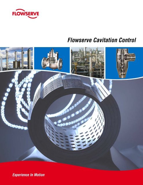
<strong>Flowserve</strong> <strong>Cavitation</strong> <strong>Control</strong><br />
1
2<br />
Index<br />
Section Page<br />
1 Introduction to <strong>Cavitation</strong> ................................... 3<br />
2 Product Comparison ........................................... 7<br />
3 ChannelStream .................................................... 10<br />
4 Multi-Z ................................................................ 11<br />
5 TigerTooth ........................................................... 12<br />
6 Cav<strong>Control</strong> .......................................................... 12<br />
7 ChannelStream Low Cv ....................................... 13<br />
8 MicroCav ............................................................. 13<br />
9 CavStream .......................................................... 14<br />
10 MultiStream ........................................................ 14<br />
11 Gestra ZK ........................................................... 15<br />
12 Kammer Cage<strong>Control</strong> Type III ............................. 16<br />
13 Kammer Stream<strong>Control</strong> Type II-1 ....................... 17<br />
14 NAF Z-Trim .......................................................... 18<br />
15 NAF A-Trim.......................................................... 19
As a fluid travels through a<br />
conventional single-seated<br />
globe-style control valve, a<br />
vena contracta (point of narrowest<br />
flow restriction) develops<br />
directly downstream<br />
of the narrowest throttling<br />
point.<br />
1. Introduction to <strong>Cavitation</strong><br />
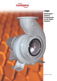
1.1 Velocity Profile Through <strong>Control</strong> Valves<br />
As a liquid travels through a control valve, a ‘vena contracta’<br />
(point of narrowest flow restriction) develops directly<br />
downstream of the throttling point. The flow area<br />
at this point is smaller than the rest of the flow path. As<br />
the flow area constricts, the velocity of the fluid rises. After<br />
the fluid passes the vena contracta the velocity drops<br />
again. See Figure 1, Velocity Through a <strong>Control</strong> Valve,<br />
for a velocity profile through a conventional single-seated<br />
globe-style control valve.<br />
Figure 1: Velocity Through a <strong>Control</strong> Valve<br />
flowserve.com<br />
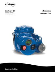
1.2 Pressure Profile Through <strong>Control</strong> Valves<br />
The increase in velocity at the vena contracta is caused<br />
by a transfer of pressure energy in the flow to velocity energy<br />
in the flow, resulting in lower pressures. As the flow<br />
leaves this high-velocity area, the velocity energy is converted<br />
back into pressure energy, and the pressure recovers.<br />
See Figure 2, Pressure Through a <strong>Control</strong> Valve, for<br />
a pressure profile through a conventional single-seated<br />
globe-style control valve.<br />
Figure 2: Pressure Through a <strong>Control</strong> Valve<br />
3
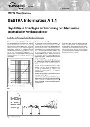
1.3 <strong>Cavitation</strong> Profile<br />
In many control valves, the pressure at the vena contracta<br />
will drop below the vapor pressure of the liquid. When<br />
this occurs, small bubbles of gas will form as the liquid<br />
vaporizes. As the pressure then rises above the vapor<br />
pressure again, these small bubbles collapse or implode<br />
as the vapor turns back into liquid. The damage is inflicted<br />
as the bubbles implode. The implosion of the vapor<br />
bubbles is very energetic and forms jets of fluid which can<br />
tear small pits into the metal. See Figure 3, Pressure Profile<br />
for <strong>Cavitation</strong>, for an illustrated profile of cavitation.<br />
4<br />
Conception<br />
Figure 3: Pressure Profile for <strong>Cavitation</strong><br />
1.4 Flashing<br />
In some cases the liquid pressure will not rise above the<br />
vapor pressure again. This is a special case known as<br />
flashing. Flashing has a distinct set of issues and solutions.<br />
Flashing requires special handling and is not covered<br />
in this document. See Figure 4, Pressure Profile for<br />
Flashing, for an illustrated profile of flashing.<br />
Figure 4: Pressure Profile for Flashing<br />
Development<br />
Manufacture<br />
1.5 <strong>Cavitation</strong> Effects<br />
<strong>Cavitation</strong> damage destroys both piping and control<br />
valves, often resulting in catastrophic failure. It causes<br />
valves to leak by eroding seat surfaces. It can drill holes<br />
through pressure vessel walls. Even low levels of cavitation<br />
will cause cumulative damage, steadily eroding parts<br />
until the part is either repaired, or it fails.<br />
1.6 <strong>Cavitation</strong> Damage<br />
<strong>Cavitation</strong> damage forms a rough surface of small microsized<br />
pits which are easy to identify with a magnifying<br />
glass or microscope, see Figure 5, <strong>Cavitation</strong> Damaged<br />
Parts. Certain types of corrosion can mimic the effects of<br />
cavitation. In these cases, the location of the damage will<br />
help distinguish cavitation. It rarely forms in narrow gaps<br />
as is common with crevice corrosion. <strong>Cavitation</strong> damage<br />
is almost always located downstream of the control valve<br />
seating areas. Occasionally cavitation bubbles can drift<br />
downstream, causing damage to piping and fittings.<br />
Figure 5: <strong>Cavitation</strong> Damaged Parts<br />
1.7 <strong>Cavitation</strong> Sound<br />
When cavitation bubbles implode they make a distinctive<br />
sound. Low level, or incipient cavitation is heard in<br />
a piping system as intermittent popping or crackling. As<br />
the pressure drop increases and the cavitation becomes<br />
more severe, the noise becomes a steady hiss or rattle that<br />
gradually increases in volume. Fully-developed or choked<br />
cavitation is often described as a sound like gravel or small<br />
rocks flowing through the pipe.
1.8 <strong>Cavitation</strong> <strong>Control</strong><br />
The ideal solution to cavitation is to reduce the pressure<br />
from inlet to outlet gradually, thus avoiding a large pressure<br />
drop at the vena contracta. <strong>Cavitation</strong> can be avoided<br />
entirely by not permitting the pressure to fall below the<br />
vapor pressure, thereby eliminating any bubble formation<br />
and subsequent collapse. See Figure 6, Gradual Pressure<br />
Reduction Profile, for an illustrated example of cavitation<br />
elimination. Another solution that can be used for lower<br />
levels of cavitation involves controlling or dissipating the<br />
energy of the imploding bubbles by isolating them away<br />
from the metal surfaces. This greatly reduces the amount<br />
of energy that the exposed surfaces of a valve need to<br />
absorb, allowing the components to resist damage.<br />
Figure 6: Gradual Pressure Reduction Profile<br />
1.9 <strong>Cavitation</strong> Measurement<br />
<strong>Cavitation</strong> in fluid flows can be measured using the vibration<br />
of imploding bubbles as the indicator. Another<br />
method is to examine damaged parts. Using the vibration<br />
method has obvious advantages, but this method requires<br />
careful isolation of the process flow that is not practical<br />
in the field. However, under lab conditions this method<br />
can provide a quick way to identify and measure the cavitation<br />
severity. Fortunately there are methods to predict<br />
and eliminate cavitation before a valve is ever exposed to<br />
damaging conditions.<br />
flowserve.com<br />
1.10 Sigma: The <strong>Cavitation</strong> Index<br />
Various cavitation indices have been used to correlate performance<br />
data to improve designs of hydraulic process<br />
equipment. A cavitation index, called Sigma (σ), has been<br />
developed and applied to quantify cavitation in control<br />
valves. Sigma represents the ratio of the potential for resisting<br />
cavity formation to the potential for causing cavity<br />
formation. This cavitation index is defined as follows:<br />
Where:<br />
σ =<br />
(P1 - Pv)<br />
(P1 - P2)<br />
P1 = Upstream pressure (psia), measured two pipe<br />
diameters upstream from the valve<br />
P2 = Downstream pressure (psia), measured six pipe<br />
diameters downstream from the valve<br />
PV = Vapor pressure of the liquid at flowing temperature<br />
Through laboratory and field testing results, acceptable<br />
operating Sigmas for eliminating cavitation (and its associated<br />
choking, noise, and damage) have been established.<br />
In general, globe valves experience minimal cavitation<br />
damage when operating at low pressure. Generally, in<br />
these cases, no cavitation control trim is necessary. Hardened<br />
trim may be all that is needed to provide a satisfactory<br />
level of protection. At a medium pressure some<br />
cavitation control is usually required. A trim that uses<br />
mutual impingement (directs opposing cavitation streams<br />
into each other) will generally suffice in this range. At high<br />
pressure drops the potential for severe cavitation damage<br />
exists and a staged pressure drop trim designed for severe<br />
service must be included in the valve’s sizing.<br />
5
6<br />
We thus have the following general categories for a typical<br />
globe valve’s operating conditions:<br />
• σ > 2.0 No cavitation is occurring.<br />
• 1.7 < σ < 2.0 No cavitation control required.<br />
Hardened trim provides protection.<br />
• 1.5 < σ < 1.7 Some cavitation control required.<br />
Mutual impingement trim may work.<br />
• 1.0 < σ < 1.5 Potential for severe cavitation.<br />
Use staged pressure drop trim.<br />
• σ < 1.0 Flashing is occurring.<br />
In actual application there are additional factors that need<br />
to be considered in sizing the valve and selecting the type<br />
of trim. However, the various types of calculated and tested<br />
Sigmas can be compared to these general categories to<br />
show how they are used. For example:<br />
Tests indicate that water flowing over-the-plug through a<br />
fully open, single-seated globe valve at 200 psia and 80°<br />
F (vapor pressure = 0.5 psia), chokes or attains maximum<br />
flow at a downstream pressure of 56 psia. The choked<br />
cavitation index is then:<br />
(200 - 0.5)<br />
σchoked = = 1.39<br />
(200 - 56)<br />
These tests also indicate that cavitation damage (σdamage)<br />
for this particular style of valve in continuous operation begins<br />
at about σdamage = 1.73 which is sooner than choked.<br />
The point at which cavitation first occurs (σincipient) can also<br />
be deduced from tests and starts at a smaller pressure<br />
drop resulting in a somewhat higher value than σdamage.<br />
If this same valve operates wide open at an upstream pressure<br />
(P1) of 500 psia and a downstream pressure (P2) of<br />
200 psia, and the water temperature increased to 180° F<br />
(vapor pressure = 7.5 psia), the operating Sigma is:<br />
(500 - 7.5)<br />
σoperating = = 1.64<br />
(500 - 200)<br />
Because this σoperating value is greater than σchoked, the valve<br />
is not choked at these conditions. However, the σoperating is<br />
less than σdamage; therefore, the valve may experience cavitation<br />
damage unless cavitation control trim or harder materials<br />
are used. In this example, our general categories<br />
show that a hardened trim using the principle of mutual<br />
impingement to control the cavitation is appropriate.<br />
Some of the other factors that affect the intensity of cavitation<br />
are the magnitude of the actual service pressure compared<br />
with test pressures, the flow path geometry, and<br />
the fluid purity. By researching these factors, methods of<br />
scaling the index for such variables have been established.<br />
This geometry and pressure scaling is not accounted for in<br />
calculating the liquid pressure recovery factor (FL) and the<br />
liquid cavitation factor (Fi) when they are used for control<br />
valve sizing. This can slightly affect the estimated Cv and<br />
possibly the valve size actually required.<br />
It should be noted that the valve type used in an application<br />
makes a difference in the level of resistance to cavitation<br />
that will be achievable for a given process. Figure 7 ,<br />
Typical Valve Recovery Coefficients, lists some general<br />
sigma limits of various valve types and trims.<br />
Valve<br />
Type<br />
Flow Trim<br />
Direction Size<br />
FL Fi σchoked* σincipient*<br />
damage<br />
Rotary Disk 90 o open full 0.56 0.49 3.17 4.16<br />
Ball 90 o open full 0.60 0.54 2.78 3.43<br />
Globe over<br />
under<br />
full<br />
all<br />
0.85<br />
0.90<br />
0.76<br />
0.81<br />
1.38<br />
1.23<br />
1.73<br />
1.52<br />
Single Stage over seat all 0.92 0.85 1.18 1.20<br />
Multi-Stage over seat all ~1.0** *** ** 1.30-1.001<br />
Figure 7: Typical Valve Recovery Coefficients<br />
* Size and pressure scale factors not included in these values.<br />
** Choking will not occur when properly applied.<br />
*** Does not apply to multi-staged trim valves.
Design<br />
2. Product Comparison<br />
Globe & Angle, Multi-Stage<br />
<strong>Cavitation</strong> Elimination<br />
Globe & Angle, Multi-Stage<br />
<strong>Cavitation</strong> Elimination<br />
Type ChannelStream Multi-Z<br />
Base Valve Mark Series Kämmer Series<br />
Size Range 1.5˝ to 36˝ 1˝ to 8˝ (DIN 25 to 200)<br />
Cv Range 6 to 720 0.03 to 137<br />
Flow Direction Flow over the plug Flow under the plug<br />
Pressure Stages 2 to 6 3 to 6<br />
Features • Tolerates Sigma as low as 1.002.<br />
• Works best in mild to moderate cavitation and can handle<br />
heavy cavitation applications.<br />
• Eliminates cavitation through a series of holes and channels<br />
to reduce the pressure in stages.<br />
• Optimized and characterized for an application with<br />
stages added as needed.<br />
• Uses small passages, impingement, expansion and<br />
contraction to reduce pressure.<br />
Design<br />
Globe & Angle, Multi-Stage<br />
<strong>Cavitation</strong> Elimination<br />
flowserve.com<br />
• Tolerates Sigma as low as 1.002.<br />
• Forgiving of solids in the process.<br />
• Linear multistage plug and retainer.<br />
• Optimized for the application.<br />
• Eliminates cavitation.<br />
• Certified and tested by boiler feed-pump manufacturers.<br />
• Seat is protected from high velocity.<br />
• Unique venturi outlet nozzle in angle valves.<br />
Globe & Angle, Single Stage<br />
<strong>Cavitation</strong> <strong>Control</strong><br />
Type TigerTooth Cav<strong>Control</strong><br />
Base Valve Mark Series Mark Series<br />
Size Range 1½˝ to 36˝ 1˝ to 24˝<br />
Cv Range 4 to 4000 1.5 to 1,000<br />
Flow Direction Flow under the plug Flow over the plug<br />
Pressure Stages 2 to 8 1<br />
Features • Tolerates Sigma as low as 1.002.<br />
• Tolerates Sigma as low as 1.2<br />
• Eliminates cavitation.<br />
• Uses a drilled hole seat retainer with stepped holes to<br />
• Stacked disks with concentric rows of teeth that increase move the vena contracta away from metal surfaces.<br />
in size provide sudden expansions and contractions to • <strong>Control</strong>s cavitation by directing the cavitation bubbles<br />
drop the pressure in stages and slow velocity.<br />
away from the metal surfaces and into opposing streams<br />
• Tolerant of dirty services.<br />
from the opposite side of the retainer. Impinging jets cre-<br />
• Optimized for a given application.<br />
ate a column of cavitation in the center of the retainer.<br />
• Disk stacks can be characterized.<br />
• Works best in low to mild cavitation.<br />
• Can be characterized.<br />
7
8<br />
Design<br />
2. Product Comparison<br />
Globe & Angle, Multi-Stage<br />
<strong>Cavitation</strong> Elimination Plug Head<br />
Globe & Angle, Multi-Stage<br />
<strong>Cavitation</strong> Elimination Plug head<br />
Type ChannelStream Low Cv MicroCav<br />
Base Valve Mark Series Mark Series<br />
Size Range 1˝ to 3˝ 1, 1½˝ and 2˝<br />
Cv Range 0.25 to 50 0.0007 to 1.25<br />
Flow Direction Flow over the plug Flow over the plug<br />
Pressure Stages 2 to 4 4 to 6<br />
Features • Tolerates Sigma as low as 1.002.<br />
• Uses the same technology as ChannelStream to eliminate<br />
cavitation, except that the stages are built into the<br />
plug head instead of the retainer.<br />
• Same performance as ChannelStream at much lower<br />
capacities.<br />
• Can be used in conjunction with ChannelStream retainers.<br />
Design<br />
Globe & Angle, Single Stage<br />
<strong>Cavitation</strong> <strong>Control</strong> Plug Head<br />
• Tolerates Sigma as low as 1.006.<br />
• Exceptionally low flow capabilities.<br />
• Utilizes a special close-guided plug with continually expanding<br />
grooves that intersect each other thus providing<br />
staged pressure drops as the fluid impinges upon itself<br />
while expanding.<br />
Globe, Multi-Stage<br />
<strong>Cavitation</strong> <strong>Control</strong><br />
Type CavStream MultiStream<br />
Base Valve Mark Series FlowTop (16”), FlowPro (12”)<br />
Size Range ½˝ to 3˝ ½˝ to 16˝ (DN 15 to 400)<br />
Cv Range 0.4 to 88 4.6 to 578 (12”)<br />
Flow Direction Flow over the plug Flow under the plug<br />
Pressure Stages 1 4<br />
Features • Tolerates Sigma as low as 1.2.<br />
• Efficient, modular design with standardized combina-<br />
• Uses the same technology as Cav<strong>Control</strong> to control cavitions for cavitation elimination.<br />
tation, except the holes are drilled into a special close- • Allows for an easy upgrade from standard trim sets.<br />
guided plug head rather than in the seat retainer. • Works well with low to mild levels of cavitation.<br />
• Impinging jets create a column of cavitation in the center • Optimized for the process conditions.<br />
of the plug head, keeping the bubbles away from metal<br />
surfaces.<br />
• Same performance as Cav<strong>Control</strong> with much lower<br />
capacities.<br />
• Can be characterized.
Globe, Multi-Stage<br />
<strong>Cavitation</strong> Elimination<br />
Globe, Multi-Stage<br />
<strong>Cavitation</strong> Elimination<br />
Globe, Multi-Stage<br />
<strong>Cavitation</strong> <strong>Control</strong><br />
flowserve.com<br />
Design<br />
ZK Cage<strong>Control</strong> - Type III Stream<strong>Control</strong> - Type II-1 Type<br />
Gestra Series Kämmer Series Kämmer Series Base Valve<br />
1˝ to 3˝ (DN 25 to 150) ½˝ to 4˝ ½˝ to 4˝ Size Range<br />
2.7 to 20 1.8 to 228 1.8 to 228 Cv Range<br />
Flow over the plug Flow under the plug Flow over the plug recommended Flow Direction<br />
4 1 or 2 1 Pressure Stages<br />
• Excellent sealing and control charac- • Works best in low to mild cavitation. • Used for low levels of cavitation. Features<br />
teristics.<br />
• Plug and/or cage characterized • Optimized for the service conditions.<br />
• Extremely wear-resistant.<br />
designs available<br />
• Plug can be used in combination<br />
• Designed on a modular assembly • Optimized for the service conditions. with Type I trim.<br />
principle.<br />
• As the plug opens in the seat, it • As the plug opens in the seat, it<br />
• Easy assembly and inspection of simultaneously opens the cage for simultaneously opens the cage for<br />
nozzle insert.<br />
effective staged pressure drops over effective staged pressure drops over<br />
• Works well with high pressure drops<br />
and heavy cavitation potential.<br />
the entire stroke length.<br />
the entire stroke length.<br />
Rotary Characterized Ball<br />
<strong>Cavitation</strong> <strong>Control</strong><br />
2. Product Comparison<br />
Rotary Ball<br />
<strong>Cavitation</strong> <strong>Control</strong><br />
Rotary Ball, Multi-Stage<br />
<strong>Cavitation</strong> Elimination<br />
Design<br />
Z-Trim Z-Trim A-Trim Type<br />
NAF-Setball NAF-Duball NAF-Duball Base Valve<br />
2˝ to 20˝ (DN 50 to 500) 2˝ to 20˝ (DN 50 to 500) 2˝ to 10˝ (DN 50 to 250) Size Range<br />
0.73 to 925 90 to 15950 6 to 3340 Cv Range<br />
Bi-directional Bi-directional Bi-directional Flow Direction<br />
1 to 5 1 to 5 6 Pressure Stages<br />
• Tight shutoff.<br />
• Tight shutoff.<br />
• A V-shaped sector provides accurate • Works well with media containing<br />
control over a wide range.<br />
solids or pulp without plugging.<br />
• Works well with media containing • Can manage high pressure drops at<br />
solids or pulp without plugging. low flow and high capacity at large<br />
• Can manage high pressure drops at openings.<br />
low flow and high capacity at large • Splits the flow into many smaller<br />
openings.<br />
flows providing 3 steps of pressure<br />
• Splits the flow into many smaller reduction.<br />
flows providing 3 steps of pressure • Used in low levels of cavitation.<br />
• Tight shutoff.<br />
• A large number of zigzag channels<br />
take the pressure drop in stages allowing<br />
cavitation to be eliminated.<br />
• From open to 45<br />
reduction.<br />
• Used in low levels of cavitation.<br />
o Features<br />
flow passes<br />
through the channels twice as the<br />
flow circles around the ball and exits<br />
through the passages not yet directly<br />
exposed. This allows extra protection<br />
at low flow/high pressure drop<br />
conditions.<br />
• Up to moderate levels of cavitation.<br />
9
3. ChannelStream<br />
Introduction<br />
ChannelStream trim prevents cavitation from forming and<br />
minimizes hydrodynamic noise in the most severe liquid applications.<br />
This design not only eliminates cavitation damage,<br />
but also provides easy maintenance and long life, even when<br />
installed in the most difficult applications. The Channel-Stream<br />
cartridge may appear similar to other competitive designs because<br />
of its drilled holes and close-fitting cylinders but here<br />
the similarity ends. Rather than acting as a flow restriction, the<br />
drilled holes in the ChannelStream cartridge are used as expansion<br />
areas for the fluid as it enters from restrictive channels<br />
machined in the outside of all interior cylinders. This prevents<br />
the fluid recovery from occurring adjacent to a critical trim surface.<br />
Successive intersections and impingement of the fluid<br />
in the restrictive channels result in additional pressure losses<br />
while expansion holes connected to the channels create a series<br />
of expansions and contractions that result in a series of highly<br />
efficient pressure drops. This staged pressure drop eliminates<br />
cavitation in most applications and minimizes the energy of<br />
cavitation that may still occur in others.<br />
Design<br />
The standard ChannelStream trim is designed for flows of 6 CV<br />
and higher, and utilizes a cartridge design in lieu of a standard seat<br />
retainer. With this design, flow is directed over the plug through<br />
a series of close-fitting cylindrical stages, called the cartridge<br />
(Figure 3.1). Flow travels first through the expansion holes in<br />
the outer cylinder and then enters the specially-engineered channels<br />
machined into the outer surface of the second cylinder. The<br />
liquid is confined to the channel until it reaches the intersecting<br />
expansion hole in the second cylinder and passes through to the<br />
next restrictive channel, and so forth.<br />
The number of stages and the flow area of the channels in each<br />
stage of the ChannelStream cartridge are designed to produce<br />
the desired overall pressure drop, while avoiding cavitation at<br />
any point. The flow area of the channel is usually greater in each<br />
successive stage in order to minimize the number of stages. This<br />
results in higher pressure drops being taken in the outer (or initial)<br />
stages as compared with the inner (or final) stages.<br />
A number of pins near the top of the cartridge, held in place with<br />
a small bead weld, hold the trim together in the correct alignment.<br />
10<br />
Figure 3.1: Cutaway of a ChannelStream cartridge<br />
The welds can be easily ground or machined out to allow disassembly<br />
and cleaning. The plug fits closely inside the cartridge<br />
bore, controlling the flow. Unbalanced and pressure-balanced<br />
designs are available.<br />
Valtek control valves with ChannelStream trim are manufactured<br />
in sizes 1.5 through 36-inch, using conventional Valtek globe-style<br />
bodies up to Class 4500. Many parts are interchangeable with<br />
conventional Valtek Mark One valves. Angle bodies in Classes 150<br />
through 600 valves in sizes 16 through 36-inch may be customfabricated.<br />
For applications requiring long strokes, long-stroking<br />
pneumatic cylinder, electric and hydraulic actuators are available.<br />
Base Valve Design<br />
The Mark series of valves.<br />
Mechanisms at Work<br />
• Sudden expansion and contraction<br />
• Frictional losses in small passages<br />
• Turbulent mixing<br />
• Mutual impingement of opposing streams<br />
• Directional changes
4. Multi-Z<br />
Introduction<br />
Users from the power generation, petrochemical and industrial<br />
chemicals industries are frequently confronted with extreme<br />
pressure differentials in their process systems - differentials of<br />
up to 400 bar are common. For this reason these customers<br />
desire continuous, steady-state flow curves with appropriate<br />
flow characteristics, long and uniform service life, as well as<br />
low maintenance costs. The valves used must satisfy certain<br />
prerequisites, such as accommodating solids in liquid media,<br />
high sound levels, high temperatures, cavitation formation, and<br />
corrosion. The Multi-Z was made for these conditions.<br />
Design<br />
Multi-Z valves are used if solids are entrained in the medium<br />
and if there is a possibility of cavitation forming. In addition<br />
this multi-stage valve is capable of reducing high-pressure differentials<br />
through a staged relief process. Multi-Z trim reduces<br />
pressure by partition division - an approach which is different<br />
than that pursued by other suppliers. The major advantage is<br />
a noticeable reduction in wear combined with extremely lownoise.<br />
The valves are optimally tailored to the specific operating conditions<br />
of the customer thus achieving significantly better results<br />
in performance characteristics. The individual stages of the plug<br />
are configured in such a manner that cavitation is impossible.<br />
Through the appropriate design of transitions and passages in<br />
the plug, solids as large as .5” in the process can be safely<br />
managed without destroying the fittings or the valve. The addition<br />
of a unique venturi outlet nozzle provides further trim and<br />
seat protection from high velocity, cavitation and flashing. The<br />
design of the linear / equal percentage multi-stage plug results<br />
in greater rangeability and outstanding control characteristics<br />
for the installed strokes.<br />
The trim can be used in both in-line globe style valves and angle<br />
style bodies currently up to 8” and Class 1500 in size.<br />
Figure 4.1: Cutaway of a Multi-Z Valve<br />
Base Valve Design<br />
The Multi-Z series of valves.<br />
Mechanisms at Work<br />
• Sudden expansion and contraction<br />
• Frictional losses in small passages<br />
• Turbulent mixing<br />
• Mutual impingement of opposing streams<br />
• Directional changes<br />
flowserve.com<br />
11
5. TigerTooth<br />
Introduction<br />
Decades of field experience has proven the sophisticated design<br />
of the TigerTooth to be very effective at cavitation elimination.<br />
Design<br />
The TigerTooth design employs highly engineered concentric<br />
grooves (or teeth) machined into the face and backside of a<br />
series of circular stacked discs which form the seat retainer.<br />
Legs separate one disc from another, providing a gap between<br />
individual discs, forming concentrically expanding flow passages.<br />
An additional benefit of this is that the passages in the<br />
TigerTooth design are self-cleaning as they grow wider from<br />
the inside to the outside. This allows large solids to easily pass<br />
through the trim.<br />
TigerTooth trim causes sudden expansion and contraction of<br />
the fluid as it passes over the teeth. The TigerTooth valve’s<br />
ability to gradually reduce pressure without generating high<br />
velocities is important for operation in service with entrained<br />
solids as well as for minimizing fluid noise.<br />
Base Valve Design<br />
The Mark series of valves.<br />
Mechanisms at Work<br />
• Sudden expansion and contraction<br />
• Frictional losses in small passages<br />
• Directional changes<br />
• Velocity reduction<br />
12<br />
6. Cav<strong>Control</strong><br />
Figure 5.1: Cutaway of TigerTooth Trim Figure 6.1: Cav<strong>Control</strong> Seat Retainer<br />
Introduction<br />
A very effective and simple method of controlling cavitation in<br />
low to mild conditions, the Cav<strong>Control</strong> trim does not attempt<br />
to eliminate cavitation but rather contain the cavitating bubbles<br />
in the center of the retainer away from the metal surfaces of<br />
the valve.<br />
Design<br />
The Cav<strong>Control</strong> design employs matched pairs of holes that<br />
cause diametrically-opposed jets of fluid to create a condition<br />
of mutual impingement in the center of the retainer. As the<br />
expanding jets of bubbles collide with each other the turbulence<br />
created dissipates the energy of the cavitating streams<br />
before they come in contact with the downstream surfaces of<br />
the valve. A small step in the drilled holes of the retainer move<br />
the vena contracta away from the inside surface of the retainer<br />
thus protecting it from the energy of the cavitation bubbles<br />
as they implode. Standardized designs are available for most<br />
applications; however characterization is possible to cover a<br />
wider range of applications.<br />
Base Valve Design<br />
The Mark series of valves.<br />
Mechanisms at Work<br />
• Mutual impingement<br />
• Turbulent mixing<br />
• Area expansion
7. ChannelStream Low Cv<br />
Figure 7.1: Low Cv ChannelStream Plug Head<br />
Introduction<br />
For low flows at high pressure drops, the Low Cv Channel-<br />
Stream uses the same technology to eliminate cavitation as is<br />
used in the larger capacity Channelstream retainers except it is<br />
built into a close-guided plug head. As the plug is stroked in<br />
the seat ring the holes are exposed or hidden as required for<br />
the needed flow capacity in its range.<br />
Design<br />
With a Cv capacity as small as 0.25 and as large as 50 this trim<br />
is intended for valves in the 1” to 3” size. This trim can also be<br />
used in conjunction with ChannelStream retainers with in this<br />
range to provide additional stages of protection. The limitations<br />
of control are set by the clearance flow passing through<br />
the tolerance gaps as the plug comes off the seat.<br />
Base Valve Design<br />
The Mark series of valves.<br />
Mechanisms at Work<br />
• Sudden expansion and contraction<br />
• Frictional losses in small passages<br />
• Turbulent mixing<br />
• Mutual impingement of opposing streams<br />
• Directional changes<br />
8. MicroCav<br />
flowserve.com<br />
Introduction<br />
For very low flows at high pressure drops the MicroCav plug<br />
head is used to eliminate cavitation. Close guided in a special<br />
seat ring, this trim can handle Sigmas as low as 1.006 and Cv’s<br />
between 0.0007 and 1.25. This trim is used in valves ranging<br />
from 1” to 1.5” to 2” in size.<br />
Design<br />
This operating mechanisms of this trim involve multiple continually<br />
expanding grooves that intersect each other as they spiral<br />
around the plug head. Not only does this create areas of sudden<br />
contraction and expansion at the groove intersections but<br />
it allows the fluid to impinge upon itself while expanding. The<br />
gradually expanding grooves also serve to reduce the velocity of<br />
the fluid as it travels along the length of the plug head.<br />
Base Valve Design<br />
The Mark series of valves.<br />
Figure 8.1: MicroCav Plug Head<br />
Mechanisms at Work<br />
• Sudden expansion and contraction<br />
• Turbulent mixing<br />
• Mutual impingement of opposing streams<br />
• Velocity reduction<br />
13
9. CavStream<br />
Introduction<br />
The CavStream plug head uses the same technology to control<br />
cavitation as the larger Cav<strong>Control</strong> trim with the exception that<br />
it is built into the plug head instead of the retainer. As the plug<br />
is stroked in the seat ring the holes are exposed or hidden as<br />
required for the needed flow capacity in its range.<br />
Design<br />
Tolerating Sigmas as low as 1.2 and covering a Cv range of 0.4<br />
to 88 for valves 0.5” to 3” the CavStream trim controls cavitation<br />
through the mutual impingement of opposing jets of fluid. As<br />
the expanding jets of bubbles collide with each other the turbulence<br />
created dissipates the energy of the cavitating streams<br />
before they come in contact with the downstream surfaces of<br />
the valve. A small step in the drilled holes of the retainer move<br />
the vena contracta away from the inside surface of the retainer<br />
thus protecting it from the energy of the cavitation bubbles as<br />
they implode.<br />
Base Valve Design<br />
The Mark series of valves.<br />
Mechanisms at Work<br />
• Mutual impingement<br />
• Turbulent mixing<br />
• Area expansion<br />
14<br />
Figure 9.1: CavStream Plug Head<br />
10. MultiStream<br />
Figure 10.1: MultiStream Trim<br />
Introduction<br />
Using a flow-under-the-plug configuration this trim is capable of<br />
controlling mild levels of cavitation.<br />
Design<br />
Using four drilled hole stages (one upstream of the plug and<br />
three downstream) and a contoured plug, the MultiStream<br />
provides good cavitation control and excellent turndown. Using<br />
small holes in each stage as contraction points and large<br />
open areas between them as expansion points the MultiStream<br />
drops the pressure in stages and divides the fluid into numerous<br />
smaller streams. This modular trim can be optimized as the<br />
process conditions require.<br />
Base Valve Design<br />
Available in the FlowTop and FlowPro valve series.<br />
Mechanisms at Work<br />
• Sudden expansion and contraction<br />
• Frictional losses in small passages<br />
• Surface impingement and turbulent mixing<br />
• Directional changes
11. ZK<br />
Figure 12.1: Gestra ZK 313 Cutaway<br />
Introduction<br />
Used in Leak-off control, drainage and warm-up, level control<br />
and injection cooling, the Gestra ZK model comes in 6 configurations.<br />
These include the ZK 29, ZK 210, ZK 412, the ZK 313,<br />
the ZK 513, and the ZK 213. The ZK has excellent sealing and<br />
control characteristics and is extremely wear-resistant while<br />
eliminating cavitation. With a unique arrangement of concentric<br />
holed sleeves this trim can be configured for a variety of operating<br />
conditions and handle extremely high pressure drops from<br />
1,400 psi to 8,120 psi. The same trim set can be configured for<br />
linear or equal percent characteristics. All this while keeping the<br />
sound level below 85 dBA.<br />
flowserve.com<br />
Design<br />
The main operating principle is based around the radial stage<br />
nozzle design which consists of several concentric sleeves with<br />
a large number of radial orifices. The orifices are arranged in<br />
parallel, but are shifted from sleeve to sleeve so that they partly<br />
overlap forming nozzles arranged in series with intermediate<br />
flash chambers. The flow through the nozzles is determined by<br />
the plug. As the plug is stroked it will either partially or completely<br />
set free the nozzles of a stage. Depending on how the<br />
holes are aligned, the characteristic of the trim can be changed<br />
from linear to equal percent. The control edge on the plug that<br />
seals the holes allows for the plug to lift well out of the seat<br />
before main flow begins, reducing wear on the seating surface<br />
and allowing the trim to maintain tight shut-off. For higher pressures<br />
a tandem shut-off configuration is employed that allows<br />
the flow velocity to be zero as the main seat opens or closes,<br />
thus excluding wire draw.<br />
An additional principle of reducing pressure drop involves drilled<br />
hole sleeves that pass flow through to channels in the next sleeve<br />
and then out the holes in that sleeve to an expansion area before<br />
passing through a final stage of holes. The plug varies the volume<br />
of the expansion area as it strokes up and down to maintain<br />
the proper expansion ratio for the fluid. The gradually increasing<br />
areas of expansion after each contraction reduce the pressure in<br />
stages to eliminate or prevent cavitation.<br />
Base Valve Design<br />
The Gestra series of valves.<br />
Mechanisms at Work<br />
• Sudden expansion and contraction<br />
• Frictional losses in small passages<br />
• Turbulent mixing<br />
• Surface and mutual impingement<br />
• Directional changes<br />
15
12. Cage<strong>Control</strong> -Type III<br />
Introduction<br />
This heavy gauge trim set can be used for reducing mild cavitation<br />
and eliminating low levels of cavitation. Three (3) configurations<br />
are possible depending on the application requirements.<br />
The possible components consist of a heavy drilled-hole cage,<br />
a skirt guided drilled-hole plug or a parabolic plug. Depending<br />
on the combination of these components, a single stage for<br />
cavitation control can be configured either with the cage and<br />
the parabolic plug or just the drilled-hole plug. A two stage<br />
cavitation control/elimination configuration can be provided by<br />
combining the drilled-hole cage with the skirt guided drilled-hole<br />
plug which also guides against the cage. The heavy duty construction<br />
of this trim allows the Type III system to be effective at<br />
higher pressure drops than the Type II-1 .<br />
16<br />
Figure 13.1: Kammer Cage<strong>Control</strong> - Type III Trim<br />
Design<br />
The main operating principle used in the Cage<strong>Control</strong> Type III<br />
trim is alternating areas of expansion and contraction. As the<br />
valve strokes the plug open to expose the holes, it simultaneously<br />
opens the cage. This keeps the area of expansion between the<br />
two stages of holes proportional to the flow through the valve<br />
providing an area of staged pressure drop. As the flow passes<br />
through the plug holes it is constricted and the flow is broken up<br />
into multiple streams. These streams exit into an area of expansion<br />
between the stages and then are constricted again by the<br />
holes of the second stage. The streams again exit in to an area<br />
of expansion as they enter the upper gallery of the valve body.<br />
When all the drilled hole components are used together this can<br />
be effective in eliminating cavitation in low conditions and controlling<br />
it in mild conditions. This configuration can be optimized<br />
to match the process conditions. Where the cavitation is<br />
low and only control is needed either the drilled hole plug or the<br />
cage can be used alone as dictated by the process Cv requirements.<br />
This trim is used in a flow-under configuration to protect the<br />
parabolic plug from cavitation damage while in a control configuration.<br />
This also allows the fluid streams to be directed into<br />
gradually expanding areas as they pass through the drilled holes<br />
thus reducing the pressure in stages and controlling velocity.<br />
Standardized designs allow for quicker deliveries and lower<br />
costs.<br />
Base Valve Design<br />
Available in a number of Kammer platforms, the most commonly<br />
used is the TotalFlow 035000 series control valve.<br />
Mechanisms at Work<br />
• Sudden expansion and contraction<br />
• Frictional losses in small passages<br />
• Turbulent mixing<br />
• Surface impingement
13. Stream<strong>Control</strong> - Type II-1<br />
Figure 14.1: Kammer Stream<strong>Control</strong> - Type II Trim<br />
Introduction<br />
There are 3 configurations of this multi-purpose trim available.<br />
The Type II-1 configuration of this trim, that uses just the skirtguided<br />
drilled-hole plug component, is the only one recommended<br />
for use in low levels of cavitating service. No screens or drilled<br />
cages are used. This Trim can be used to control low levels of<br />
cavitation in either a flow over (recommended) or a flow under<br />
direction.<br />
Design<br />
In a flow-over configuration, using just the plug, this trim works<br />
on the principle of mutual impingement and turbulent mixing to<br />
control cavitation. This works well for controlling low levels of<br />
cavitation.<br />
In a flow-under application and at lower levels of cavitation the<br />
Kammer<br />
TotalFlow<br />
035000<br />
flowserve.com<br />
same plug works on the principle of creating a restriction by splitting<br />
the fluid into many small streams and allowing them to expand<br />
into a larger area.<br />
Standardized designs allow for quicker deliveries and lower<br />
costs.<br />
Base Valve Design<br />
Available in a number of Kammer platforms, the most commonly<br />
used is the TotalFlow 035000 series control valve.<br />
Mechanisms at Work<br />
• Mutual impingement<br />
• Turbulent mixing<br />
• Area expansion<br />
17
14. Z-Trim<br />
Introduction<br />
Z-Trim is offered in a notched V-ball or a full-port ball and combines<br />
the benefits of an advanced control valve with the simplicity<br />
of a ball valve. Most effective with medium pressure drops<br />
and able to handle low flows at higher pressure drops, the Z-trim<br />
can be used to effectively control cavitation. The trim also works<br />
very well with media containing particles like fibers without risk<br />
of clogging. Using the standard Setball or Duball as a platform,<br />
adding the Z-Trim requires only one part to be changed.<br />
Design<br />
The simple design of the Z-Trim controls low levels of cavitation<br />
by passing the fluid through as many as five stages of pressure<br />
reduction. The passages from one stage to the next split the<br />
flow in to many smaller streams creating alternating areas of expansion<br />
and contraction. The increasing passage areas in each<br />
subsequent stage of the Z-Trim allows the fluid to expand while<br />
controlling velocities.<br />
18<br />
Figure 16.1: Setball <strong>Control</strong> Valve with Z-Trim<br />
Figure 16.2: Duball <strong>Control</strong> Valve with Z-Trim<br />
As the valve opens, fewer stages are taken until the ball is open<br />
and the valve develops full capacity. This feature gives effective<br />
cavitation control at the low end, where pressure drops are high,<br />
and still delivers the high capacity expected from a ball valve<br />
when fully open.<br />
Base Valve Design<br />
The Z-Trim is available in the Duball, Setball, and ShearStream<br />
SB control valves.<br />
Mechanisms at Work<br />
• Sudden expansion and contraction<br />
• Turbulent mixing<br />
• Directional changes
15. A-Trim<br />
Introduction<br />
Capable of eliminating moderate cavitation completely, the<br />
A-Trim provides exceptional control in the simplicity of a ball<br />
valve. Very effective at low flows and higher pressure drops,<br />
this trim works best in clean media.<br />
Design<br />
The ball of the A-Trim is made up of many small zigzag channels<br />
creating a large number of deflections as well as small areas of<br />
expansion and contraction. This allows the pressure drop to<br />
be taken in many small steps. The area of each channel can be<br />
varied in order to optimize the trim for specific process conditions.<br />
This design is particularly effective in eliminating cavitation<br />
when the valve is first opened and up to 450 of rotation. It is<br />
during this stage of orientation that the lowest flows and highest<br />
pressure drops are encountered and the greatest amount of<br />
protection is required. As the fluid enters an exposed channel<br />
Figure 17.1: A-Trim for Duball<br />
flowserve.com<br />
on the upstream side of the ball it is forced to pass around the<br />
ball between the seals and through the channels that are not<br />
yet exposed in order to exit the trim. The passing of the fluid<br />
through the channels twice provides additional stages of pressure<br />
reduction where it is needed most. As the ball continues<br />
to open past 45 0 to its full capacity the fluid passes through<br />
more and more of the channels only once. As a result the valve<br />
capacity will increase appreciably and still maintain the ability<br />
to eliminate cavitation.<br />
Base Valve Design<br />
The A-Trim is available in the Duball.<br />
Mechanisms at Work<br />
• Sudden expansion and contraction<br />
• Frictional losses in small passages<br />
• Directional changes<br />
19
20<br />
FCD FCENBR0068-01 Printed in USA. 01/09<br />
To find your local <strong>Flowserve</strong> representative:<br />
For more information about <strong>Flowserve</strong> <strong>Corporation</strong>, visit<br />
www.flowserve.com or call USA 1 800 225 6989<br />
<strong>Flowserve</strong> <strong>Corporation</strong> has established industry leadership in the design and manufacture of its products. When properly<br />
selected, this <strong>Flowserve</strong> product is designed to perform its intended function safely during its useful life. However,<br />
the purchaser or user of <strong>Flowserve</strong> products should be aware that <strong>Flowserve</strong> products might be used in numerous<br />
applications under a wide variety of industrial service conditions. Although <strong>Flowserve</strong> can (and often does) provide<br />
general guidelines, it cannot provide specific data and warnings for all possible applications. The purchaser/user must<br />
therefore assume the ultimate responsibility for the proper sizing and selection, installation, operation, and maintenance<br />
of <strong>Flowserve</strong> products. The purchaser/user should read and understand the Installation Operation Maintenance (IOM)<br />
instructions included with the product, and train its employees and contractors in the safe use of <strong>Flowserve</strong> products in<br />
connection with the specific application.<br />
While the information and specifications contained in this literature are believed to be accurate, they are supplied for<br />
informative purposes only and should not be considered certified or as a guarantee of satisfactory results by reliance<br />
thereon. Nothing contained herein is to be construed as a warranty or guarantee, express or implied, regarding any<br />
matter with respect to this product. Because <strong>Flowserve</strong> is continually improving and upgrading its product design, the<br />
specifications, dimensions and information contained herein are subject to change without notice. Should any question<br />
arise concerning these provisions, the purchaser/user should contact <strong>Flowserve</strong> <strong>Corporation</strong> at any one of its worldwide<br />
operations or offices.<br />
© 2006 <strong>Flowserve</strong> <strong>Corporation</strong>, Irving, Texas, USA. <strong>Flowserve</strong> is a registered trademark of <strong>Flowserve</strong> <strong>Corporation</strong>.<br />
flowserve.com<br />
<strong>Flowserve</strong> Beaumont<br />
2920 W. Cardinal Dr.<br />
Beaumont, TX, 77705<br />
Phone: +1 409 842 6600<br />
<strong>Flowserve</strong> Houston<br />
5909 W. Loop S.<br />
Suite 200<br />
Bellaire, TX 77401<br />
Phone: +1 713 218 4200<br />
<strong>Flowserve</strong> Deer Park<br />
5114 Railroad St.<br />
Deer Park, TX 77536<br />
Phone: +1 281 479 9500<br />
Regional Headquarters<br />
<strong>Flowserve</strong> America<br />
1350 N. Mt. Springs Pkwy.<br />
Springville, UT 84663 USA<br />
Telephone: +1 801 489 8611<br />
<strong>Flowserve</strong> Asia<br />
12 Tuas Ave. 20, 638824<br />
Republic of Singapore<br />
Telephone: +65 862 3332<br />
<strong>Flowserve</strong> (Austria) GmbH<br />
<strong>Control</strong> Valves - Villach Operation<br />
Kasernengasse 6<br />
9500 Villach<br />
Austria<br />
Telephone: +43 (0) 4242 41181 0<br />
<strong>Flowserve</strong> India <strong>Control</strong>s Pvy. Ltd<br />
Plot # 4, 1A, E.P.I.P, Whitefield<br />
Bangalore Kamataka<br />
India 560 066<br />
Telephone: +91 80 284 10 289<br />
<strong>Flowserve</strong> Australia<br />
14 Dalmore Dr.<br />
Scoresby, Victoria, Australia 3179<br />
Telephone: +61 3 9759 3300<br />
<strong>Flowserve</strong> China<br />
5B5, Hanwei Plaza<br />
7 Guanghua Road<br />
Bejing China 100004<br />
Telephone: +86 10 6561 1900<br />
Main Sales Offices (North America)<br />
To locate your local sales representative<br />
go to www.flowserve.com/eim/<br />
SalesLocator.<br />
<strong>Flowserve</strong> Edmonton<br />
9044 18th St.<br />
Edmonton, Alberta, T6P 1K6<br />
Phone: +1 780 449 4850<br />
<strong>Flowserve</strong> Baton Rouge<br />
12134 Industriplex Blvd.<br />
Baton Rouge, LA 70809<br />
Phone: +1 225 751 9880<br />
<strong>Flowserve</strong> Philadelphia<br />
104 Chelsea Pkwy.<br />
Boothwyn, PA 19061<br />
Phone: +1 610 497 8600<br />
<strong>Flowserve</strong> Pittsburgh<br />
1300 Parkway View Dr.<br />
Pittsburgh, PA 15205-1410<br />
Phone: +1 412 787 8803