

view or download report - Oak Ridge National Laboratory
view or download report - Oak Ridge National Laboratory
view or download report - Oak Ridge National Laboratory

Create successful ePaper yourself
Turn your PDF publications into a flip-book with our unique Google optimized e-Paper software.
Printed in the United States of America. Available from<br />
<strong>National</strong> Technical Inf<strong>or</strong>mation Service<br />
U.S. Department of Commerce<br />
5285 P<strong>or</strong>t Royal Road, Springfield, Virginia 22161<br />
NTIS price codes-Printed Copy: A07 Microfiche A01<br />
This rep<strong>or</strong>t was prepared as an account of w<strong>or</strong>k spons<strong>or</strong>ed by an agency of the<br />
United StatesGovernment. Neither the United States Government n<strong>or</strong> any agency<br />
thereof, n<strong>or</strong> any of their employees, makes any warranty, express <strong>or</strong> implied, <strong>or</strong><br />
assumes any legal liability <strong>or</strong> responsibility f<strong>or</strong> the accuracy, completeness, <strong>or</strong><br />
usefulness of any inf<strong>or</strong>mation, apparatus, product, <strong>or</strong> process disclosed, <strong>or</strong><br />
represents that its use would not infringe privately owned rights. Reference herein<br />
to any specific commercial product, process, <strong>or</strong> service by trade name, trademark,<br />
manufacturer, <strong>or</strong> otherwise, does not necessarily constitute <strong>or</strong> imply its<br />
end<strong>or</strong>sement, recommendation, <strong>or</strong> fav<strong>or</strong>ing by the United States Government <strong>or</strong><br />
any agency thereof. The <strong>view</strong>s and opinions of auth<strong>or</strong>s expressed herein do not<br />
necessarily state <strong>or</strong> reflect those of the United StatesGovernment <strong>or</strong> any agency<br />
thereof.
DEVELOPMENT OF A BRAUN LINEAR ENGINE-DRIVEN,<br />
HEAT-ACTUATED HEAT PUMP<br />
FINAL REPORT<br />
Date Published - July 1984<br />
Rep<strong>or</strong>t Prepared by<br />
Tectonics Research, Inc.<br />
9556 West Bloomington Freeway<br />
Minneapolis, MN 55431<br />
Honeywell Inc., Technology Strategy Center<br />
1700 West Highway 36<br />
Roseville, MN 55113<br />
Honeywell Inc., C<strong>or</strong>p<strong>or</strong>ate Technology Center<br />
10701 Lyndale Avenue South<br />
Bloomington, MN 55420<br />
under<br />
Subcontract 86X-61619C<br />
f<strong>or</strong><br />
<strong>Oak</strong> <strong>Ridge</strong> <strong>National</strong> Lab<strong>or</strong>at<strong>or</strong>y<br />
<strong>Oak</strong> <strong>Ridge</strong>, Tennessee 37831<br />
operated by<br />
MARTIN MARIETTA ENERGY SYSTEMS, INC.<br />
f<strong>or</strong> the<br />
U.S. DEPARTMENT OF ENERGY<br />
Under Contract No. DE-AC05-840R21400<br />
ORNL/Sub/80-61619/1
iii<br />
F<strong>or</strong>ew<strong>or</strong>d<br />
This Final Rep<strong>or</strong>t is prepared f<strong>or</strong> Union Carbide C<strong>or</strong>p<strong>or</strong>ation, Nuclear<br />
Division, on a program f<strong>or</strong> Development of a Braun Engine-Driven, Heat Pump<br />
(Contract No. 86X-61619C). It includes a summary of component analyses,<br />
design and tests, and a description of breadboard design, fabrication, test<br />
and results.<br />
The rep<strong>or</strong>t is <strong>or</strong>ganized in "reverse chronological" <strong>or</strong>der, directing the<br />
reader through progressively m<strong>or</strong>e detailed background and analysis supp<strong>or</strong>ting<br />
the program results and conclusions:<br />
* Section 1, Summary and Conclusions, highlights the program<br />
findings.<br />
* Section 2, Test Results, is a summary of the key final test<br />
results.<br />
* Section 3, Breadboard System Description, is a functional and<br />
physical description of the heat pump system that<br />
generated the data f<strong>or</strong> this rep<strong>or</strong>t.<br />
* Section 4, Data Analysis, is an interpretation and rationale f<strong>or</strong><br />
data analysis and summaries of program data output.<br />
o Section 5, Component Development, is a summary of the design,<br />
analysis and testing tasks from the component level<br />
through breadboard system debugging.
v<br />
TABLE OF CONTENTS<br />
Section Page<br />
S PROGRAM OVERVIEW SUMMARY S-L<br />
PROGRAM BACKGROUND S-1<br />
PROGRAM PHILOSOPHY S-1<br />
PROGRAM OBJECTIVES S-2<br />
Attainment of Objectives S-3<br />
PROGRAM TEAM MEMBERS S-3<br />
1 SUMMARY AND CONCLUSIONS 1-1<br />
1.1 SEALS 1-1<br />
1.2 BREADBOARD HEAT PUMP (BR-105R) 1-2<br />
1.3 ENGINE PERFORMANCE 1-4<br />
1.4 CONCLUSIONS 1-4<br />
1.5 RECOMMENDATIONS 1-5<br />
2 TEST RESULT SUMMARY 2-1<br />
2.1 BR-105 ENGINE PERFORMANCE 2-1<br />
Conclusions 2-3<br />
2.2 HEAT PUMP PERFORMANCE 2-3<br />
3 BREADBOARD SYSTEM DESCRIPTION 3-1<br />
3.1 BRAUN BR-105R ENGINE/REFRIGERANT COMPRESSOR 3-2<br />
3.1.1 Engine 3-2<br />
3.1.2 Balance Mechanism 3-6<br />
3.1.3 Speed Control 3-6
vi<br />
TABLE OF CONTENTS (Continued)<br />
Section Page<br />
3.1.4 Compress<strong>or</strong>/Valve 3-7<br />
3.1.5 Hermetic Seal 3-8<br />
3.1.6 Controls 3-10<br />
3.2 TEST RIG 3-10<br />
3.2.1 Controls 3-13<br />
3.3 INSTRUMENTATION AND DATA ACQUISITION 3-13<br />
3.4 TYPICAL TEST OPERATING PROCEDURES 3-17<br />
4 TEST DATA ANALYSIS 4-1<br />
4.1 TEST PLAN AND ATTAINED CONDITIONS 4-2<br />
4.2 DATA RESULTS--BR-105R TESTS 4-4<br />
4.2.1 Repeatability 4-4<br />
4.2.2 Energy Balance 4-19<br />
4.2.3 Compress<strong>or</strong> Maps 4-20<br />
4.3 BR-105 HIGH-EFFICIENCY, FUEL-INJECTED ENGINE TESTS 4-20<br />
4.4 DATA EVALUATION AND ANALYSIS 4-23<br />
4.4.1 Energy Input/Output Accountability 4-23<br />
4.4.2 Energy Accountability--High Efficiency<br />
Engine Potential 4-23<br />
4.4.3 Further Improvements 4-24<br />
4.5 STEADY-STATE PERFORMANCE 4-26
vii<br />
TABLE OF CONTENTS (Concluded)<br />
Section Page<br />
5 COMPONENT DEVELOPMENT 5-1<br />
5.1 ENGINE 5-8<br />
5.1.1 Fuel Injection 5-10<br />
5.2 COMPRESSOR 5-11<br />
5.2.1 Compress<strong>or</strong> Valves 5-11<br />
5.2.2 Miscellaneous 5-12<br />
5.3 SPEED CONTROL 5-12<br />
5.4 SEALS 5-13<br />
5.5 CONTROLS 5-15<br />
5.6 TEST RIG 5-15<br />
REFERENCES R-1<br />
APPENDIX A REPORT ON TEST RESULTS, EXHAUST EMISSIONS AND BHP<br />
DATA ON MODEL BR-105 A-1<br />
APPENDIX B TEST PLAN AND DATA ACQUISITION AND REDUCTION FOR<br />
BR-105R LINEAR ENGINE/COMPRESSOR B-l
ix<br />
LIST OF FIGURES<br />
Figure Page<br />
2-1 Actual and Projected COP's f<strong>or</strong> Braun Linear<br />
Engine-Driven Heat Pump 2-4<br />
2-2 Braun Engine-Driven Heat Pump Heating Perf<strong>or</strong>mance<br />
at 40°F Ambient Temperature 2-6<br />
3-1 Basic Elements of Breadboard Heat Pump System 3-1<br />
3-2 Layout of Braun BR-105R Model (Breadboard)<br />
Engine/Compress<strong>or</strong> 3-3<br />
3-3 BR-105R Lubrication System 3-6<br />
3-4 Compress<strong>or</strong> Operation, Varying Clearance Volume 3-8<br />
3-5 Braun Hermetic Seal Dynamic Perf<strong>or</strong>mance 3-9<br />
3-6 Test/Demonstration System - Simplified Schematic 3-11<br />
3-7 View From Pump End 3-12<br />
3-8 View From Compress<strong>or</strong> End 3-12<br />
3-9 Automatic and Manual Data Acquisition Flow 3-16<br />
4-1 BR-105R Compress<strong>or</strong> Test Conditions and Heat Pump Envelope 4-3<br />
4-2 Refrigerating Capacity Over Range of Evap<strong>or</strong>ating and<br />
Condensing Temperatures Tested 4-21<br />
4-3 Refrigerant Mass Flow Over Range of Evap<strong>or</strong>ating and<br />
Condensing Temperatures Tested 4-22<br />
4-4 Energy Flow Diagram--BR-105R Engine/Compress<strong>or</strong> Test<br />
Data, Based on Run D 4-25<br />
4-5 Energy Flow Diagram--Combined Test Results (BR-105R<br />
Compress<strong>or</strong> Plus BR-105 Engine) 4-25<br />
4-6 Measured and Projected Thermal COP's f<strong>or</strong> BR-105R 4-27
x<br />
LIST OF FIGURES (Concluded)<br />
Figure Page<br />
4-7 Braun Engine-Driven Heat Pump Heating Perf<strong>or</strong>mance<br />
at 45°F Ambient Temperature 4-27<br />
4-8 Compress<strong>or</strong> W<strong>or</strong>k versus Evap<strong>or</strong>ating Temperature 4-29<br />
5-1 Program Over<strong>view</strong> 5-3<br />
5-2 Viscosity Comparison 5-18<br />
5-3 Thermal Conductivity Comparison 5-18<br />
5-4 Density Comparison 5-19<br />
5-5 Specific Heat Comparison 5-19
xi<br />
LIST OF TABLES<br />
Table Page<br />
3-1 Test Rig Design Specifications 3-14<br />
3-2 Data Points and Sens<strong>or</strong>s 3-15<br />
3-3 W<strong>or</strong>st Case Data Accuracy Analysis 3-17<br />
4-1 Data Run A<br />
4-2 Data Run B 4-6<br />
4-3 Data Run C<br />
4-4 Data Run D 4-8<br />
4-5 Data Run E<br />
4-6 Data Run F<br />
4-7 Data Run G 4-11<br />
4-8 Data Run H 4-12<br />
4-9 Data Run I<br />
4-10 Data Run J<br />
4-11 Data Run K<br />
4-12 Data Run L<br />
4-5<br />
4-7<br />
4-9<br />
4-10<br />
4-13<br />
4-14<br />
4-13 Summary of Steady-State Conditions -- BR-105R<br />
Engine/Compress<strong>or</strong> Tests 4-17<br />
4-14 Condenser and Evap<strong>or</strong>at<strong>or</strong> Energy Balance 4-19<br />
5-1 Dowtherm "J" Heat Transfer Fluid Health and<br />
Hazard Comparison<br />
5-2 Dowtherm "J" Material Compatibility 5-21<br />
4-15<br />
4-16<br />
5-20
xii<br />
PHOTOGRAPHS OF BRAUN LINEAR ENGINE TEST SETUP
xi i<br />
PHOTOGRAPH OF BRAIJN I. NEAR ENGINE HEAT PUMP TEST SETUP
PROGRAM BACKGROUND<br />
S-1<br />
PROGRAM OVERVIEW SUMMARY<br />
The present program was initially contracted as a Phase I component develop-<br />
ment program, including evaluation of two alternate basic Braun engine/<br />
compress<strong>or</strong> concepts, to be followed by a Phase II program, f<strong>or</strong> the full<br />
development of the selected concept and to include a market analysis and<br />
testing and demonstration of the prototype engine/refrigerant compress<strong>or</strong><br />
unit. Sh<strong>or</strong>tly after its inception in February 1981, the program was<br />
redirected to include the prototype development and breadboard demonstration<br />
from Phase II and to retain only those Phase I component development eff<strong>or</strong>ts<br />
deemed critical to proof-of-concept of the engine/refrigerant compress<strong>or</strong><br />
package. The maj<strong>or</strong> program changes made to accommodate the breadboard<br />
prototype development and testing were the elimination of the evaluation of<br />
the alternative engine/compress<strong>or</strong> concept, the reduction of controls<br />
development w<strong>or</strong>k, operating the engine in the carbureted mode only and the<br />
development and inclusion of the refrigerant test rig and its controls,<br />
instrumentation and data acquisition system. The program was extended from<br />
lay 1982 through March 1983 to accommodate the breadboard engine/refrigerant<br />
compress<strong>or</strong> development and debugging.<br />
The present program was preceded by a Linear Hermetic Seal Development<br />
Program (Contract No. 86X-61613C). The final rep<strong>or</strong>t of that program has been<br />
issued [1], and the seal concept developed therein was extended and<br />
inc<strong>or</strong>p<strong>or</strong>ated into the present program.<br />
PROGRAM PHILOSOPHY<br />
The program plan was to evolve from a proven Braun Model BR-105 engine/air<br />
compress<strong>or</strong> to an operational BR-105R engine/refrigerant compress<strong>or</strong> in a<br />
breadboard configuration. The program embodied the elements of analysis,
S-2<br />
design, fabrication, assembly and test at component, subsystem and system<br />
levels. Within the philosophy of "proof-of-concept," a number of design<br />
guidelines were laid down early in the program that governed all subsequent<br />
system development:<br />
* In-house parts fabrication,<br />
* Carbureted engine on breadboard system,<br />
* Propane fuel on breadboard system,<br />
* Manual (and semiautomated) controls,<br />
* Off-the-shelf basic seal components.<br />
It should be recognized that each of these criteria may impose "limits" on<br />
the configuration, operation and/<strong>or</strong> perf<strong>or</strong>mance of the system as described in<br />
this rep<strong>or</strong>t. These criteria were, however, compatible with the program Scope<br />
of W<strong>or</strong>k and were dictated by considerations of program schedule and available<br />
funding.<br />
PROGRAM OBJECTIVES<br />
Program objectives are to:<br />
* Develop and test basic components of a gas [Propane (LPG)]<br />
engine-driven heat pump system sized f<strong>or</strong> application in the light<br />
commercial building sect<strong>or</strong>, and implement a breadboard.<br />
* Measure steady-state perf<strong>or</strong>mance of the breadboard system over a range<br />
of simulated outdo<strong>or</strong> and indo<strong>or</strong> temperatures and demonstrate operation<br />
in both heating and cooling modes.<br />
* By simulation, based on test data, develop estimates of annual<br />
perf<strong>or</strong>mance to goals of COP=1.2 in heating and 0.6 in cooling.
Attainment of Objectives<br />
S-3<br />
The following objectives were attained:<br />
* The components of a propane-fueled, carbureted engine-driven light<br />
commercial-sized heat pump system were developed and tested.<br />
* Demonstrations were given of the compress<strong>or</strong>, seals, engine, sound<br />
suppression and breadboard heat pump system in the heating mode.<br />
* Perf<strong>or</strong>mance data were obtained and rep<strong>or</strong>ted on by an independent<br />
testing lab<strong>or</strong>at<strong>or</strong>y on a high efficiency, fuel injected BR-105<br />
engine/air compress<strong>or</strong>.<br />
* Steady-state running of the BR-105R engine/refrigerant compress<strong>or</strong> unit<br />
in the breadboard heat pump system over almost the full heating and<br />
cooling range was carried out.<br />
* Steady-state perf<strong>or</strong>mance data was taken and analyzed over a range of<br />
simulated indo<strong>or</strong> and outdo<strong>or</strong> temperatures f<strong>or</strong> the breadboard heat pump<br />
system in the heating mode.<br />
* Some steady-state points were run in the cooling mode range to<br />
indicate the unit's capability in that mode, although no steady-state<br />
perf<strong>or</strong>mance data in the cooling was analyzed.<br />
* Estimates of annual perf<strong>or</strong>mance by simulation were not carried out<br />
within the given funding and time constraints.<br />
PROGRAM TEAM MEMBERS<br />
The participants in this program and their general areas of responsibilities<br />
are as follows:
S-4<br />
* TECTONICS RESEARCH INCORPORATED (TECTONICS),<br />
Mr. A. (Tom) Braun, Technical Direct<strong>or</strong><br />
- BR105R technology development, analysis, design, fabrication,<br />
testing.<br />
- Engine/Compress<strong>or</strong> data acquisition and analysis.<br />
* HONEYWELL TECHNOLOGY STRATEGY CENTER (TSC),<br />
Mr. Donald N. Carlson, P.E., Program Manager<br />
- Program management.<br />
- Test rig design, fabrication and operation.<br />
- Data acquisition and analysis.<br />
* HONEYWELL CORPORATE TECHNOLOGY CENTER (CTC),<br />
Dr. Ulrich Bonne, Consultant<br />
- Simulation and data analysis.<br />
This program was supp<strong>or</strong>ted by the U.S. Department of Energy as part of the<br />
Heat Actuated Heat Pump Technology Program, and directed by Ge<strong>or</strong>ge Privon of<br />
<strong>Oak</strong> <strong>Ridge</strong> <strong>National</strong> Lab<strong>or</strong>at<strong>or</strong>y, Energy Division.
1-1<br />
SECTION 1.0<br />
SUMMARY AND CONCLUSIONS<br />
This program began with a technology represented by a Braun Model BR-105<br />
free-piston engine extensively tested and proven in an air compression<br />
application. An alternate version of the engine, the BR-300, was previously<br />
tested as a refrigerant compress<strong>or</strong>. Air compress<strong>or</strong> models of the BR-105 had<br />
sucessfully accumulated a total of over 45,000 hours of operation. A single<br />
unit had been operated under full load conditions f<strong>or</strong> 15,000 hours (two years<br />
of continuous running) with negligible wear and wide margins f<strong>or</strong> additional<br />
sustained running. Engine perf<strong>or</strong>mance, in the spark ignition mode, had<br />
demonstrated a brake efficiency in the <strong>or</strong>der of 34 percent. The balancer f<strong>or</strong><br />
vibration-free operation had been and is being used extensively by Braun<br />
licensees in the U.S.A. and Europe in their commercial compress<strong>or</strong> lines with<br />
sales w<strong>or</strong>ldwide.<br />
Starting with this proven engine technology, and continuing through design,<br />
fabrication and testing of a breadboard heat pump system, this program has<br />
served to demonstrate the goal of proof-of-concept f<strong>or</strong> the Braun engine<br />
technology application to heat pumps. In the course of this heat pump appli-<br />
cation program, several maj<strong>or</strong> advances, both in demonstrated accomplishment<br />
and knowledge, have been made. In the following paragraphs, the present<br />
state of development is defined and recommendations offered f<strong>or</strong> future<br />
continuation of this program.<br />
1.1 SEALS<br />
The requirement f<strong>or</strong> a viable, linear hermetic seal was recognized early as<br />
the single most critical element in this development. Under a separate<br />
contract [1], preceding the present one, and based on an independently<br />
demonstrated Braun linear hermetic seal concept, a hermetic seal f<strong>or</strong> the
1-2<br />
BR-105R breadboard compress<strong>or</strong> was designed to "infinite life" criteria. In<br />
this program, the design was further developed, tested and demonstrated in<br />
the refrigerant environment. The seal was proven, although extended life<br />
(life cycle) tests have not yet been conducted.<br />
To maximize the probability of success in the BR-105 seal development, a<br />
philosophy of utilizing proven and commercially available seal components was<br />
employed. This made available to the program not only timely deliveries of<br />
seals, but also a wealth of manufacturer's experience and data f<strong>or</strong> inclusion<br />
in in-house developed analytical programs. As a consequence of this<br />
philosophy, however, the engine/compress<strong>or</strong> unit, to a certain extent, had to<br />
be adapted to the resulting seal configuration.<br />
A logical and realizable extension to this seal w<strong>or</strong>k is a similar eff<strong>or</strong>t<br />
beginning with heat pump perf<strong>or</strong>mance specifications and then designing and<br />
developing the seal specifically f<strong>or</strong> the application. Knowledge gained on<br />
this program clearly indicates that a high probability of success of such an<br />
eff<strong>or</strong>t, not only f<strong>or</strong> the Braun engine application, but others, such as the<br />
Stirling engine, as well. Such a program would also involve suitable seal<br />
manufacturers.<br />
1.2 BREADBOARD HEAT PUMP (BR-105R)<br />
A breadboard heat pump system consisting of the BR-105R engine/refrigerant<br />
compress<strong>or</strong> unit and a refrigerant/hydronic test rig, capable of simulating a<br />
full range of outdo<strong>or</strong> conditions, has been designed, fabricated, assembled,<br />
tested and demonstrated. A wide operational range of measured data have been<br />
collected and analyzed, meeting a primary objective of the program. In<br />
operation, this system has demonstrated the capability of:<br />
* Reliable, and safe starting, running and stopping;<br />
* Operating at, and adjusting to, variable load conditions;
1-3<br />
* Stable, steady-state operation and data collection over heat pump<br />
heating conditions ranging from -6 to 60 F evap<strong>or</strong>ating temperature,<br />
with quantitative data obtained from 6 to 28 F;<br />
* Providing test data exhibiting stability and repeatibility with good<br />
heat balance within ±10 percent;<br />
* Meeting anticipated perf<strong>or</strong>mance projections with additional<br />
development eff<strong>or</strong>t.<br />
These demonstrated capabilities supp<strong>or</strong>t the program goal and attainment of<br />
proof-of-concept.<br />
Additionally, the following high-probability capabilities have been identi-<br />
fied in these tests:<br />
* Consistent with expectations, the perf<strong>or</strong>mance numbers of the car-<br />
bureted unit were low, but substantial improvements will be gained by<br />
utilizing the high efficiency, fuel-injected standard Braun engine.<br />
Minimum expected perf<strong>or</strong>mance with this and other related changes is a<br />
cooling COP of not less than 0.7 at 95 F ambient and a heating COP<br />
of not less than 1.4 at 17 F ambient.<br />
* Demonstrated operation was limited to 6 to 60 F due to constraints<br />
put on the breadboard engine/compress<strong>or</strong> unit (time and funding).<br />
Optimization of the c<strong>or</strong>responding design parameters f<strong>or</strong> the high<br />
efficiency version of the BR-105R engine/compress<strong>or</strong> is expected to<br />
result in its automatic operation throughout the entire heating and<br />
cooling range of -20 to 115°F.
1.3 ENGINE PERFORMANCE<br />
1-4<br />
Aside from the heat pump system test results, the maj<strong>or</strong> claim and expectation<br />
of high efficiency of the standard fuel-injected Braun engine was demon-<br />
strated by means of tests conducted by a prominent, independent testing lab.<br />
These tests supp<strong>or</strong>ted and c<strong>or</strong>rob<strong>or</strong>ated earlier in-house and outside tests of<br />
the standard BR-105 engine. The engine in these tests used the fuel injec-<br />
tion system (LPG) <strong>or</strong>iginally planned f<strong>or</strong> breadboard use. The measured data<br />
of these engine tests have been combined with the measured data of the<br />
carbureted engine/ compress<strong>or</strong> of the breadboard to develop predicted system<br />
perf<strong>or</strong>mances of the Braun heat pump system.<br />
A natural gas injection system has also been developed and concept-tested,<br />
wherein low gas Line pressures are boostea to the desired engine injection<br />
pressure.<br />
1.4 CONCLUSIONS<br />
The program met the main objective of demonstrating operation of the Braun<br />
engine/compress<strong>or</strong> in a heat pump mode. It also demonstrated high efficiency<br />
of the standard fuel-injected Braun engine. Perf<strong>or</strong>mance fact<strong>or</strong>s with the<br />
carbureted breadboard engine version were, as expected, on the low side and<br />
the range of operation below maximum. However, in addition to the<br />
demonstration of the engine/ compress<strong>or</strong> in the heat pump mode the program<br />
produced data and developed knowledge and understanding necessary to identify<br />
the next set of tasks f<strong>or</strong> this development. With further development these<br />
results can readily lead to the verification and integrated demonstration of<br />
the high efficiency capabilities of the Braun linear engine heat pump over<br />
the full range of heating and cooling conditions.
1.5 RECOMMENDATIONS<br />
1-5<br />
The knowledge, experience and data derived from the breadboard and associated<br />
tests and w<strong>or</strong>k clearly indicate the necessary steps f<strong>or</strong> further study and<br />
demonstration of reproducible automatic and highly efficient operation of the<br />
Braun engine/refrigerant compress<strong>or</strong> over the full range of heating and<br />
cooling conditions. Implementation of these steps are recommended and should<br />
include:<br />
* Adaptation of fuel injection,<br />
* Compress<strong>or</strong> resizing,<br />
* Compress<strong>or</strong> clearance resizing,<br />
* Compress<strong>or</strong> valve resizing and tuning,<br />
* Full adaptation of BR-105 controls concepts to BR-105R.<br />
These recommendations f<strong>or</strong> continued development w<strong>or</strong>k, supp<strong>or</strong>ted by the test<br />
data and demonstrations described in this rep<strong>or</strong>t, have been presented to an<br />
expert consultant team provided by, and w<strong>or</strong>king with, ORNL. The technical<br />
discussions and demonstrations conducted at Tectonics Research, Inc.,<br />
included such proprietary data as necessary and beyond the scope of the data<br />
presented herein.
2-1<br />
SECTION 2.0<br />
TEST RESULT SUMMARY<br />
In addition to qualitative proof-of-concept accomplishments, quantitative<br />
measurements and data were obtained, both with respect to the BR-105R engine/<br />
refrigerant compress<strong>or</strong> and the gas-injected standard BR-105 engine/air<br />
compress<strong>or</strong>. While the breadboard system with the carbureted engine produced<br />
low perf<strong>or</strong>mance fact<strong>or</strong>s, the measurements and data obtained are shown to<br />
demonstrate the strong potential f<strong>or</strong> substantial improvement by adaptation of<br />
the gas-injected standard BR-105 engine. Test data and analyses from which<br />
this summary is drawn are detailed in Section 4.0.<br />
2.1 BR-105 ENGINE PERFORMANCE<br />
The fuel-injected standard BR-105 engine, driving an air compress<strong>or</strong> f<strong>or</strong> load,<br />
was tested f<strong>or</strong> perf<strong>or</strong>mance and emissions by an independent testing lab<strong>or</strong>at<strong>or</strong>y<br />
(Colt Industries). Their results (Appendix A) can be summarized as follows:<br />
* The best engine settings gave an engine-indicated power and cycle<br />
efficiency of 20.1 ihp and 38.5 percent, respectively. The resulting<br />
overall engine/air compress<strong>or</strong> unit efficiency is 30.8 percent based on<br />
a measured compress<strong>or</strong>-indicated h<strong>or</strong>sepower of 16.1.<br />
* The engine brake h<strong>or</strong>sepower is less than the engine-indicated power<br />
but greater than the compress<strong>or</strong>-indicated power due to the compress<strong>or</strong><br />
piston ring friction. Each h<strong>or</strong>sepower attributable to compress<strong>or</strong> ring<br />
friction results in an engine brake efficiency of approximately two<br />
percentage points greater than the overall unit efficiency. In this<br />
case the 16.1 compress<strong>or</strong>-indicated h<strong>or</strong>sepower would become 17.1<br />
engine-brake h<strong>or</strong>sepower and result in a brake efficiency of 32.7<br />
percent.
2-2<br />
Exhaust emissions were at expected levels and responded to ignition<br />
timing as a typical spark-ignited engine. The lowest NOx emissions<br />
were obtained at best engine settings as typical f<strong>or</strong> the particular<br />
scavenging air flow at the given engine speed and load. Lower NOx<br />
emission could be obtained by reducing the engine fuel flow per cycle<br />
<strong>or</strong> increasing the amount of air trapped per cycle and by a similar<br />
means.<br />
An interesting test was the variable gas injection timing. The data<br />
shows the marked effect gas injection timing has on exhaust gas<br />
hydrocarbons and the engine indicated specific fuel consumption. The<br />
result clearly shows that much improvement in reduced hydrocarbons and<br />
engine fuel consumption can be realized by the proposed redesign of<br />
the gas injection system. The present injection system has a gas<br />
injection p<strong>or</strong>t that traps a small volume of gas during each cycle. A<br />
p<strong>or</strong>tion of this gas volume passes through the engine with the<br />
scavenging air on the subsequent cycle without going through the<br />
combustion cycle, and accounts f<strong>or</strong> the high level of hydrocarbons in<br />
the exhaust system.<br />
The actual gas trapped in the injection p<strong>or</strong>t is a function of its<br />
volume and the cylinder pressure at the time the gas valve closes.<br />
Typical hydrocarbon levels were 550 grams per hour <strong>or</strong> 1 1/4 pounds per<br />
hour. It is estimated that as much as 1 pound per hour could be<br />
propane, depending on other engine sources f<strong>or</strong> hydrocarbons. If<br />
two-thirds of this propane loss could be eliminated the engine fuel<br />
consumption would be reduced by 10 percent. With such fuel savings<br />
the efficiency from Run No. 2 would result in the following<br />
outstanding efficiencies:
Conclusions<br />
2-3<br />
Measured Possible<br />
Engine-indicated efficiency 38.5 42.8<br />
Overall unit (engine and<br />
compress<strong>or</strong>) efficiency 30.8 34.2<br />
Estimated brake efficiency 32.7 36.3<br />
* Engine emissions of NOx are typical of a spark-ignited natural gas<br />
engine while the CO emissions are higher than need be f<strong>or</strong> a<br />
well-developed engine.<br />
* Measured hydrocarbons are very high due to the present gas injection<br />
system design employed (and can be substantially reduced by redesign<br />
of the injection system).<br />
* Engine perf<strong>or</strong>mance is good f<strong>or</strong> an engine with a 4 1/2-inch b<strong>or</strong>e. The<br />
engine mechanical efficiency was 85 percent based on estimated<br />
compress<strong>or</strong> ring friction of one h<strong>or</strong>sepower.<br />
Note: Present engine brake efficiency of 32.7 percent compares with<br />
27 to 28 percent of those rep<strong>or</strong>ted in the A.D. Little, Inc. rep<strong>or</strong>t [2].<br />
Possible engine brake efficiency of 36.3 percent is substantially<br />
higher than rep<strong>or</strong>ted anywhere else f<strong>or</strong> engines of this size.<br />
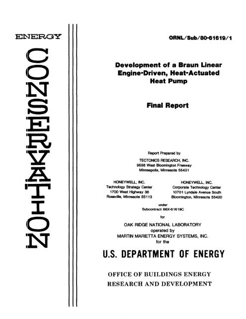
2.2 HEAT PUMP PERFORMANCE<br />
The breadboard heat pump system, which included a fully-instrumented<br />
refrigerant (R22)/hydronic test rig, provided data from which fuel utiliza-<br />
tion efficiency <strong>or</strong> thermal COP can be estimated. Figure 2-1 is a summary of<br />
the results obtained from breadboard tests alone, those combined with the
0<br />
(3<br />
z<br />
3-<br />
wU<br />
PROJECTED (IB = 36 PERCENT)<br />
I 2-<br />
M 2s = =<br />
-<br />
-- BREADBOARD PLUS COLT DATA (7B = 32 PERCENT)<br />
2g ==,~-=-- ~ ~I ~.. BREADBOARD DATA (1B = 13 PERCENT)<br />
I-<br />
0--------I I I I I I<br />
0 10 20 30 40 50 60<br />
APPROXIMATE AMBIENT TEMPERATURE (°F)<br />
NOTE: ASSUMES 75 PERCENT RECOVERY<br />
OF EXHAUST COOLING AND UNBURNED 300<br />
FUEL ENERGY.<br />
Figure 2-1. Actual and Projected Heating COPs f<strong>or</strong> Braun Linear<br />
Engine-Driven Heat Pump
2-5<br />
gas-injected standard BR-105 engine test results and a projection based on<br />
fuel injection system improvement. The assumption made in developing this<br />
thermal COP is a 75 percent utilization of all heat of fuel into the engine,<br />
*<br />
which is not converted into w<strong>or</strong>k acting on the compress<strong>or</strong> piston. Because<br />
this COP is related to point-of-use fossil fuel utilization gross <strong>or</strong> HHV<br />
efficiency, it does not include the cost of operating electric auxiliaries,<br />
which is consistent with standard U.S. practice in rating gas- <strong>or</strong> oil-fueled<br />
appliances f<strong>or</strong> central space conditioning (example: AGA/ANSI bench test of<br />
minimum of 75 percent efficiency).<br />
A cross-plot of the heat pump COP's, shown in Figure 2-1 f<strong>or</strong> an outdo<strong>or</strong><br />
temperature of 40 F (at which steady-state COP approximates seasonal COP<br />
f<strong>or</strong> an average U.S. climate), is shown in Figure 2-2 as a function of engine<br />
brake efficiency. Supp<strong>or</strong>ting data points (averaged) from two sets of<br />
experiments are also shown, together with an estimted limit derived from<br />
projected fuel injection improvements.<br />
This is consistent with the assumptions made in the A.D. Little, Inc., rep<strong>or</strong>t<br />
f<strong>or</strong> DOE [2].
_J<br />
2.0 -<br />
IMPROVED FUEL INJECTION<br />
FUEL INJECTION<br />
u_ BREADBOARD C<br />
o 1.5 -vA /<br />
^^ 30 ASSUMES 75 PERCENT RECOVERY OF<br />
e0^~ " Y1~ " Pa~~~~pv<br />
M^~~~ ^EXHAUST, COOLING AND UNBURNED<br />
ui<br />
I 2.0<br />
FUEL ENERGY.<br />
O 1 -=*~ ^.0-_<br />
D® BR105R R0 AS TESTED IN BREADBOARD<br />
zo<br />
z<br />
' -- -~(CARBURETED ENGINE)<br />
_ STANDARD BR105 (FUEL INJECTION)<br />
I 0.5- (3) IMPROVED BR105 (FUEL INJECTION)<br />
LJ 3-0082<br />
0. 0<br />
0.10 0.15 0.20 0.25 0.30 0.35 0.40<br />
WB ENGINE BRAKE EFFICIENCY<br />
Figure 2-2. Braun Engine-Driven Heat Pump Heating Perf<strong>or</strong>mance at 40 F<br />
Ambient Temperature
3-1<br />
SECTION 3.0<br />
BREADBOARD SYSTEM DESCRIPTION<br />
Consistent with program objectives to test and demonstrate, a breadboard heat<br />
pump system was designed, fabricated and assembled. The component develop-<br />
ment w<strong>or</strong>k supp<strong>or</strong>ting the breadboard system is detailed in Section 5.0. This<br />
section details the description, operating procedures, functions and features<br />
of the final breadboard system, which consists of the following maj<strong>or</strong><br />
components (Figure 3-1):<br />
* Braun BR-105R engine/refrigerant compress<strong>or</strong>,<br />
* Hydronic/Freon test rig,<br />
* Instrumentation and data acquisition system.<br />
CONTROLS CONTROLS<br />
LUBE<br />
SPEED CONTROL BR105R - REFRIGERANT/HYDRONIC<br />
SEALS ENGINE/COMPRESSOR TEST RIG<br />
CARBURETION<br />
REFRIGERANT<br />
INSTRUMENTATION INTERFACE INSTRUMENTATION<br />
DATA ACQUISITION<br />
AND<br />
REDUCTION<br />
Figure 3-1. Basic Elements of Breadboard Heat Pump System
3-2<br />
3.1 BRAUN BR-105R ENGINE/REFRIGERANT COMPRESSOR<br />
A functional diagram of the breadboard unit is shown in Figure 3-2. The<br />
BR-105R is a free-piston, spark-ignited, two-stroke machine. The engine and<br />
compress<strong>or</strong> pistons are joined at opposite ends of a rod that also contains<br />
the balancer mechanism, bouncer piston, seal mechanism and seal. This<br />
experimental BR-105R is 72 inches long, 20.5 inches high, 14 inches wide and<br />
weighs approximately 500 pounds. It is mounted h<strong>or</strong>izontally on a<br />
28-inch-high test stand.<br />
3.1.1 Engine<br />
The engine was adapted f<strong>or</strong> this heat pump application from the 6-inch stroke<br />
BR-105 engine/air compress<strong>or</strong>. Significant engine parameters in the initial<br />
BR-105R version were:<br />
B<strong>or</strong>e 4.5 inches<br />
Stroke 4.254 inches<br />
Fuel propane (LPG)<br />
Cooling:<br />
Head - water<br />
Cylinder - air<br />
Running speed - to 1500 cpm<br />
Engine Perf<strong>or</strong>mance--The BR-105 engine/air compress<strong>or</strong> has been tested twice by<br />
independent lab<strong>or</strong>at<strong>or</strong>ies in the past seven years. From these tests, a<br />
c<strong>or</strong>relation between BR-105 air compress<strong>or</strong> perf<strong>or</strong>mance and engine brake<br />
thermal efficiency was established. The c<strong>or</strong>relation that has been proven is<br />
the ratio of compress<strong>or</strong> output to fuel input versus brake efficiency. It has<br />
been determined from the independent tests that 525 CFM compress<strong>or</strong> output per<br />
pound per minute of fuel input is equivalent to 34 percent engine brake<br />
efficiency. The notation commonly used is 525 ft /lb. The engine brake<br />
thermal efficiency of the carbureted version of the BR-105 engine measured<br />
consistently as 18 percent efficiency which is equivalent to 280 ft /lb.
ENGINE BALANCER AND BOUNCER SEAL MECHANISM/SEALS REFRIGERANT<br />
COMPRESSOR<br />
Figure 3-2. Layout of Braun BR-105R Model (Breadboard) Engine Compress<strong>or</strong><br />
3 0077
3-4<br />
The "thermal efficiency" measurement on the BR-105R engine/refrigerant<br />
compress<strong>or</strong> (Section 4.0) was based on the A H of the Freon from the<br />
compress<strong>or</strong> intake to compress<strong>or</strong> discharge. This A H is assumed to be "the<br />
engine brake power" in the breadboard measurements. This method was never<br />
calibrated as the air compress<strong>or</strong> measurements had been. Theref<strong>or</strong>e, there may<br />
be a fair degree of uncertainity in the "thermal efficiency" measurements<br />
taken during the breadboard tests. With this uncertainty, the BR-105R is<br />
rep<strong>or</strong>ted in Section 4.0 as having 13 percent efficiency.<br />
Speed--The speed of the BR-105R engine has been controlled through the<br />
range of 1000 to 1500 cpm. Typically, during the tests f<strong>or</strong> data, the<br />
operating speed of the engine varied from approximately 1100 to 1500 cpm.<br />
Very little eff<strong>or</strong>t was made to alter the speed under load with the speed<br />
control.<br />
Carburetion--The breadboard engine is carbureted using an IMPCO Model<br />
110-8, vacuum-operated, LP gas carburet<strong>or</strong> that has not been changed <strong>or</strong><br />
modified in the program. The two basic adjustments on the carburet<strong>or</strong> are the<br />
fuel mixture and throttle position. The fuel mixture is set at a point f<strong>or</strong><br />
consistent engine operation. No detailed tests have been perf<strong>or</strong>med to locate<br />
the best power and efficiency settings. The throttle position is n<strong>or</strong>mally in<br />
the full open position, except during extremely low load conditions that may<br />
be experienced during certain phases of the startup procedure. During the<br />
program, carburetion was selected to facilitate breadboard development. The<br />
initial program goal f<strong>or</strong> the fuel metering system was f<strong>or</strong> a natural gas<br />
injection system; however, from schedule and cost consideration, it first was<br />
decided to operate with an existing propane injection system. Later, when<br />
the BR-105R was converted to a 4-inch machine because of the use of off-the-<br />
shelf seal components, carburetion was selected f<strong>or</strong> the final breadboard<br />
tests, within given time constraints it being m<strong>or</strong>e readily adaptable to the<br />
4-inch stroke operation. A fuel injection development was also carried out,<br />
in parallel, and was subjected to detailed tests (Section 5.1.1).
3-5<br />
Stroke--The stroke limit of 4.0 inches was dictated from consideration of<br />
seal procurement early in the component development p<strong>or</strong>tion of the program<br />
(Section 5.1). Stroke modulation capability has been demonstrated. The<br />
actual stroke is determined by the compress<strong>or</strong> load in conjunction with<br />
control adjustments to the bounce control function (see Subsection 3.1.3).<br />
Lubrication--The BR-105R utilizes a cam-actuated, positive displacement<br />
oil pump, which circulates the primary oil supply directly to the balance<br />
mechanism (Figure 3-3). The oil pump is located in a gravity-fed oil sump<br />
below the balance mechanism. The cam-actuated oil regulat<strong>or</strong> delivers oil to<br />
the engine and speed control cylinders.<br />
Ignition--A microprocess<strong>or</strong> ignition system controls the operation of the<br />
engine. This prototype ignition controller contains an EPROM single-chip<br />
microcomputer that offers great flexibility and simplicity in varying engine<br />
control parameters.<br />
During the starting phase, the microprocess<strong>or</strong> ignition system controls the<br />
positioning of the piston, fuel flow and ignition. During the running phase,<br />
it controls the capacitive discharge ignition.<br />
Engine Intake--The engine is a two-stroke cycle type with a scavenging<br />
process similar to a crankcase scavenged engine. Being a free piston engine,<br />
there is no crankcase, but the back side of the engine piston serves as the<br />
scavenge pump as in a crankcase-scavenged engine. The effective pumping<br />
volume of the engine is increased by the addition of a small booster pump<br />
which is driven by the balancer mechanism. The quantity of scavenged air is<br />
controlled by a throttle plate in the carburet<strong>or</strong>.<br />
Exhaust--The exhaust system is a fixed pipe length at 42 inches. Only a<br />
limited amount of exhaust tuning was perf<strong>or</strong>med.
3-6<br />
BALANCE<br />
MECHANISM<br />
HIGH VOLUME<br />
<strong>or</strong>1-ENGINE SPEED<br />
ENGINE CONTROL<br />
CYLINDER SUMP CYLINDER<br />
(BOUNCER)<br />
OIL<br />
PUMP<br />
(4 DROPS PER HOUR) OIL<br />
FILTER<br />
3.1.2 Balance Mechanism<br />
OIL REGULATOR<br />
Figure 3-3. BR-105R Lubrication System<br />
11<br />
(4 DROPS PER HOUR)<br />
The standard, proven Braun balance mechanism of the BR-105 was used in the<br />
BR-105R. Its function is to balance inertial f<strong>or</strong>ces of the moving piston<br />
assembly. It consists of two pinions driven by the center shaft that drives<br />
the floating "matchbox" counterweight assembly in the opposite sense of the<br />
moving piston assembly, providing completely balanced operation. The mass of<br />
the balance system was modified to account f<strong>or</strong> the mass of the additional<br />
moving components of the BR-105R system.<br />
3.1.3 Speed Control<br />
The function of the speed control device is to modulate the capacity of the<br />
machine. This device utilizes two gas chambers which act as variable
3-7<br />
"stiffness" springs. The speed of the machine can be raised and lowered by<br />
changing the stiffness of these springs. The net result f<strong>or</strong> the heat pump is<br />
a c<strong>or</strong>responding direct increase <strong>or</strong> reduction in capacity.<br />
Startup--During the experimental phase the refrigerant system was equlized<br />
f<strong>or</strong> startup.<br />
After the initial adjustments are made to stabilize the stroke, the<br />
refrigerant load on the compress<strong>or</strong> increases, accomplishing, in effect, a<br />
gradual abs<strong>or</strong>ption of the refrigerant load in proper balance with the<br />
engine's energy.<br />
Running--When equilibrium is established following startup, changing intake/<br />
discharge conditions at the compress<strong>or</strong> requires change in the output of the<br />
BR-105R. This is accomplished by c<strong>or</strong>responding modulation of the bounce<br />
pressures.<br />
3.1.4 Compress<strong>or</strong>/Valve<br />
The single acting compress<strong>or</strong> piston is 7.0 inches in diameter and operates in<br />
an "oil-free" mode with teflon piston rings. The compress<strong>or</strong> stroke is<br />
identical to that of the engine. In this machine, the compress<strong>or</strong> can operate<br />
with a varying clearance volume (see Figure 3-4). This feature, along with<br />
the capability of variable speed, will play a role in modulating capacity to<br />
meet varying system loads. On the breadboard unit the full extent of<br />
capacity modulation was not exercised because of time and funding restraints.<br />
The combined suction and discharge valve used during tests of the compress<strong>or</strong><br />
alone and during BR-105R tests was a commercially available, concentric type<br />
f<strong>or</strong> use in refrigerant compress<strong>or</strong>s.<br />
No "tuning" of valve springs was done during final testing.
FULL LOAD<br />
3-8<br />
INTAKE<br />
II il<br />
I --<br />
SWEPT STROKE. SS .- C )- CLEARANCE<br />
VOLUME<br />
P /<br />
7<br />
_-- SS C<br />
ZERO LOAD I<br />
I 3-o0079<br />
----- SS -_ -- C_<br />
Figure 3-4. Compress<strong>or</strong> Operation, Varying Clearance Volume<br />
3.1.5 Hermetic Seal<br />
Figure 3-5 summarizes the analytical results, supp<strong>or</strong>ted by extensive seal<br />
tests, which illustrates the potential infinite life (safety fact<strong>or</strong> of 1.0<br />
c<strong>or</strong>responding to the manufacturer's "safe" criteria) characteristic of the<br />
Braun hermetic seal. Complete seal design analysis results are given in<br />
Reference [1].
A<br />
3-9<br />
t I<br />
~\ ~\ _.- ISEAL, 300G 0.4<br />
0.4 /<br />
0.3 -\,<br />
\<br />
\\-.'<br />
\<br />
/<br />
· -- 3SEALS 3 C -0.5<br />
^ \v -0.i~~~~~~~~~~~~~~~0.6<br />
0 x 1 2.75- SEAL,3 3SEALS, 300G .7<br />
0.2- I I I I<br />
| \ ^s. '"'" ~" ""-^3 SEALS, 1906 " 3<br />
0.1 01 0.005-INCH 2.75-x 1.25-INCH PLATESEAL,<br />
/1<<br />
0.005-INCH PLATE<br />
03 \<br />
-DESIGN<br />
POINT<br />
OCDESIGN<br />
VALID FOR FOR AP ACROSS -- LINEAR DEFLECTION<br />
SEALS LESS THAN 20 psi 5-INCH STROKE<br />
Figure 3-5. Brau Hermetic Seal (NO DYNAMICS) Dynamic Perfomance<br />
0 10 20 30 40 50 60<br />
CONVOLUTIONS<br />
Figure 3-5. Braun Hermetic Seal Dynamic Perf<strong>or</strong>mance<br />
S/<br />
--
3-10<br />
The final perf<strong>or</strong>mance data runs of the BR-105R were conducted with a commer-<br />
cially available sliding rod seal in place of the Braun hermetic seal. This<br />
decision was made to avoid any potential damage to the one available set of<br />
hermetic seals on hand. Damage could have occurred from inadvertent oil<br />
contamination <strong>or</strong> from the piston reaching its mechanical limit (which<br />
occasionally happened during the tuning and development w<strong>or</strong>k). The small<br />
amount of refrigerant leakage past the sliding rod seal was felt to have no<br />
significant effect on the quality of data thus obtained.<br />
3.1.6 Controls<br />
The various control elements of the BR-105R have been previously discussed<br />
and are summarized:<br />
* Carburet<strong>or</strong> - fuel/air mixture to engine,<br />
* Variable Ignition Timing - best burning in engine,<br />
* Bounce Chamber - speed/stroke control,<br />
* Engine Intake - throttle control.<br />
The net result of these controls, the concepts of which had been developed<br />
f<strong>or</strong> the standard BR-105 engine/air compress<strong>or</strong> and BR-300, is to provide<br />
control of the engine/compress<strong>or</strong> in response to changing load (compress<strong>or</strong><br />
suction and discharge pressure and flow) and environmental conditions.<br />
3.2 TEST RIG<br />
The system selected to provide a refrigerant compress<strong>or</strong> test bed and Braun<br />
engine heat pump demonstration system is a liquid-to-liquid system. Figure<br />
3-6 is a simplified system schematic and Figures 3-7 and 3-8 are as-built<br />
pictures of the system.
O - RECORDED INSTRUMENTATION<br />
E) - VISUAL INSTRUMENTATION<br />
- CONTROL SENSORS<br />
HEAT TRANSFER<br />
TANK<br />
K<br />
3-11<br />
5<br />
T)S~ ~PURGE (~ X ~<br />
{ v -- ( - i-T(a_ it<br />
.2-.- (5uS^--H^^ - --<br />
SHELL AND TUBE<br />
EVAPORATOR<br />
H PTI<br />
½ ___ IANTU T C^)^@__OmP<br />
SHELL AND TUBE<br />
CONDENSER<br />
--- FREON LIQUID<br />
'-"\_____________ | FREON VAPOR<br />
HEAT TRANSFER FLUID<br />
Figure 3-6. Test/Demonstration System - Simplified Schematic
3-12<br />
Figure 3-7. View from Pump End<br />
Figure 3-8. View from Compress<strong>or</strong> End
3-13<br />
The liquid-to-liquid system is basically a quasi-adiabatic system utilizing a<br />
standard shell and tube condenser and evap<strong>or</strong>at<strong>or</strong> and heat transfer tank. The<br />
heat source and heat sink are provided by the condenser and evap<strong>or</strong>at<strong>or</strong><br />
respectively. The thermal energy transfer is provided by the heat transfer<br />
fluid and occurs in the mixing header and heat transfer tank. The excess<br />
heat (compress<strong>or</strong> w<strong>or</strong>k) is purged to the atmosphere.<br />
The temperatures of the condenser and evap<strong>or</strong>at<strong>or</strong> is controlled and driven<br />
individually by the amount of heat transfer fluid that is recirculated<br />
through the condenser and evap<strong>or</strong>at<strong>or</strong>. The heat transfer rate in the<br />
condenser and evap<strong>or</strong>at<strong>or</strong> is independently controlled by the flow rate of the<br />
heat transfer fluid through each circuit. The heat transfer tank temperature<br />
is controlled by purging the excess heat (compress<strong>or</strong> w<strong>or</strong>k) to the atmosphere<br />
by circulating the heat transfer fluid through a fan-cooled radiat<strong>or</strong>.<br />
Table 3-1 is a list of the maj<strong>or</strong> components and technical specifications of<br />
the system.<br />
3.2.1 Controls<br />
The controls on the demonstration/test rig system provide interactive control<br />
of the refrigerant circuit and hydronic circuit; there is currently no inter-<br />
active control system between the refrigerant load and the engine/compress<strong>or</strong>.<br />
The demonstration/test rig control system contains both an automatic and<br />
manual mode f<strong>or</strong> temperature control. F<strong>or</strong> the test/demonstration the test<br />
systems were operated in the manual mode.<br />
3.3 INSTRUMENTATION AND DATA ACQUISITION<br />
Table 3-2 is a list of data points and types of sens<strong>or</strong>s used to measure data<br />
employed in perf<strong>or</strong>mance measurements and calculations.
3-14<br />
Table 3-1. Test Rig Design Specifications<br />
CONDENSER, LIQUID-COOLED SHELL AND TUBE, 30 TON NOMINAL<br />
CONDENSING TEMPERATURE 95° TO 125°F<br />
LIQUID LINLET TEMPERATURE 750 TO 105 F<br />
LIQUID OUTLET TEMPERATURE 85° TO 115 F<br />
HEAT REJECTION 10 TO 30 TONS<br />
LIQUID FLOW RATE 0 TO 130 GPM<br />
EVAPORATOR, SHELL AND TUBE LIQUID CHILLER, 47 TON NOMINAL<br />
SUCTION TEMPERATURE -30° TO 55°F<br />
LIQUID INLET TEMPERATURE -20° TO 75°F<br />
LIQUID OUTLET TEMPERATURE VARIABLE RANGE<br />
CAPACITY 5 TO 25 TONS<br />
LIQUID FLOW RATE 0 TO 130 GPM<br />
REFRIGERANT R-22<br />
REFRIGERANT CONTROL THERMOSTATIC EIGHT HAND EXPANSION<br />
VALVE<br />
HEAT TRANSFER TANK 36 INCHES IN DIAMETER BY 8 FEET 6<br />
INCHES IN LENGTH, 400-GALLON CAPACITY<br />
HEAT TRANSFER FLUID 330 GALLONS DOWTHERM "J"<br />
PUMP (P1 AND P2) 130 GPM, 110-i,,T.T HD., 7-1/2 HP<br />
PUMP (P3) 30 GPM, 45-FOOT HD., 1 HP<br />
WEIGHT (FULL) 6550 POUNDS<br />
WEIGHT (EMPTY) 4150 POUNDS<br />
DIMENSIONS OF "PACKAGE" 4 FEET WIDE BY 7 FEET 6 INCHES HIGH<br />
BY 16 FEET LONG
ENGINE<br />
3-15<br />
Table 3-2. Data Points and Sens<strong>or</strong>s<br />
DATA POINT SENSOR UNITS<br />
FUEL CONSUMPTION DIGITAL SCALE LBS<br />
COOLANT<br />
WATER INLET TEMPERATURE THERMOCOUPLE, TYPE T °F<br />
WATER OUTLET TEMPERATURE THERMOCOUPLE, TYPE T °F<br />
WATER FLOW RATE BUCKET AND STOP WATCH GPM<br />
AIR INLET TEMPERATURE THERMOCOUPLE, TYPE T °F<br />
AIR OUTLET TEMPERATURE THERMOCOUPLE, TYPE T °F<br />
AIR FLOW RATE MANOMETER INCHES H20<br />
EXHAUST GAS ANALYSIS<br />
EXHAUST TEMPERATURE<br />
C02 HARIBA C02 GAS ANALYZER PERCENT<br />
CO HARIBA CO GAS ANALYZER PERCENT<br />
CH4 ANARAD GAS ANALYZER PPM<br />
STROKE MANUAL - STROKE DIAGRAM INCH<br />
SPEED MANUAL - OSCILLOSCOPE CPM<br />
TIME DATA LOGGER CLOCK HOUR-MINUTE-<br />
SECOND<br />
COMPRESSOR<br />
STOP WATCH<br />
OSCILLOSCOPE<br />
DISCHARGE PRESSURE PRESSURE TRANSDUCER psia<br />
DISCHARGE TEMPERATURE THERMOCOUPLE, TYPE T °F<br />
SUCTION PRESSURE PRESSURE TRANSDUCER psia<br />
SUCTION TEMPERATURE THERMOCOUPLE, TYPE T OF<br />
CONDENSER<br />
REFRIGERANT INLET TEMPERATURE THERMOCOUPLE, TYPE T °F<br />
REFRIGERANT OUTLET TEMPERATURE THERMOCOUPLE, TYPE T °F<br />
REFRIGERANT TEMPERATURE AT BACK-TO-BACK THERMOCOUPLE OF<br />
FLOWMETER<br />
REFRIGERANT FLOW RATE TURBINE FLOWMETER GPM<br />
DOWTHERM "J" INLET TEMPERATURE THERMOCOUPLE, TYPE T °F<br />
DOWTHERM "J" OUTLET TEMPERATURE THERMOCOUPLE, TYPE T °F<br />
DOWTHERM "J" AT BACK-TO-BACK THERMOCOUPLE °F<br />
DOWTHERM "J" FLOW RATE TURBINE FLOW METER GPM<br />
EVAPORATOR<br />
REFRIGERANT INLET TEMPERATURE THERMOCOUPLE, TYPE T °F<br />
REFRIGERANT OUTLET TEMPERATURE THERMOCOUPLE, TYPE T °F<br />
DOWTHERM "J" INLET TEMPERATURE THERMOCOUPLE, TYPE T O F<br />
DOWTHERM "J" OUTLET TEMPERATURE THERMOCOUPLE, TYPE T °F<br />
DOWTHERM "J" AT BACK-TO-BACK THERMOCOUPLE °F<br />
DOWTHERM "J" FLOW RATE TURBINE FLOW METER GPM
3-16<br />
The data from the sens<strong>or</strong>s is sampled and processed by a data logger and is in<br />
turn printed out and rec<strong>or</strong>ded at the rate of 45 channels of data every 30<br />
seconds. The data is further processed by computer into engineering units<br />
and calculated data (Figure 3-9).<br />
SENSED<br />
THERMOCOUPLES<br />
PRESSURE TRANSDUCERS<br />
FLOWMETERS<br />
SCALE * FUEL RATE<br />
WATT TRANSDUCER D<br />
LOGGER<br />
OATA TERMINAL<br />
RECORDED:<br />
* TAPE<br />
MANUAL * PRINTOUT<br />
ENGINE COOLANT<br />
* AIR m<br />
· WATER m COMPUTER<br />
SPEED _ TERMINAL<br />
STROKE<br />
EXHAUST GAS ANALYSIS<br />
COMPUTER<br />
ENGINEERING<br />
UNITS<br />
COMPUTED<br />
DATA<br />
DATA<br />
PLOTS<br />
Figure 3-9. Automatic and Manual Data Acquisition Flow<br />
Table 3-3 shows the the<strong>or</strong>etical w<strong>or</strong>st case accuracy of the data based on<br />
sens<strong>or</strong> and data logger specifications and sens<strong>or</strong> calibration. Sens<strong>or</strong> err<strong>or</strong><br />
<strong>or</strong> offset is continually accounted f<strong>or</strong> in the computer software, resulting in<br />
good c<strong>or</strong>relation in the heat balances between the refrigerant and heat<br />
transfer fluid in the condenser and evap<strong>or</strong>at<strong>or</strong> circuits. Test rig checkout<br />
with a 10 ton electric compress<strong>or</strong> indicated a variation of 2 to 5 percent<br />
heat balance in the condenser and evap<strong>or</strong>at<strong>or</strong> circuits.
TEMPERATURE<br />
3-17<br />
Table 3-3. W<strong>or</strong>st Case Data Accuracy Analysis<br />
CONDENSER ±0.5°F (5.0 PERCENT)<br />
EVAPORATOR ±0.5°F (5.0 PERCENT)<br />
PRESSURES<br />
Ps (COMPRESSOR SUCTION) ±1.0 PERCENT<br />
PCD (COMPRESSOR DISCHARGE) ±0.8 PERCENT<br />
FLOW RATE<br />
FR (R-22) ±1.0 PERCENT<br />
FE (DOWTHERM "J") ±0.5 PERCENT<br />
FC (DOWTHERM "J") ±0.5 PERCENT<br />
Q DOW EVAPORATOR ±6.0 PERCENT<br />
Q R-22 EVAPORATOR ±6.0 PERCENT<br />
HEAT BALANCE EVAPORATOR ±7.0 PERCENT<br />
Q DOW CONDENSER ±6.0 PERCENT<br />
Q R-22 CONDENSER ±6.0 PERCENT<br />
HEAT BALANCE CONDENSER ±7.0 PERCENT<br />
3.4 TYPICAL TEST OPERATING PROCEDURES<br />
When operating the breadboard system f<strong>or</strong> perf<strong>or</strong>mance data, the primary objec-<br />
tive is to stablize all parameters of the system at a point representing a<br />
heat pump operating condition [i.e., simulated indo<strong>or</strong> and outdo<strong>or</strong> environment<br />
(see Appendix B)]. When stabilized, the data are accumulated over a typical<br />
5-minute period and averaged. Such data are given and analyzed in Section 4.
3-18<br />
To establish the desirable steady-state operating point the breadboard system<br />
is typically run as described below.<br />
The engine starting procedure has been described in Subsection 3.1.3 and<br />
generally involves transferring the engine output to the load imposed by the<br />
refrigerant system (test rig).<br />
At this point, the compress<strong>or</strong> discharge pressure is fairly close to what the<br />
system pressure was bef<strong>or</strong>e startup, typically between 100 and 150 psig. The<br />
compress<strong>or</strong> suction pressure is held at an intermediate level to control the<br />
compress<strong>or</strong> load during the startup phase. The next step is to proceed to the<br />
test conditions. First, the condensing temperature is raised (and theref<strong>or</strong>e<br />
the discharge pressure) to the desired level. Second, the compress<strong>or</strong> suction<br />
pressure is raised <strong>or</strong> lowered until the desired evap<strong>or</strong>ating temperature is<br />
achieved. Once these two conditions are fairly stable, the compression ratio<br />
of the engine is set. At this point, the engine controls can be pretty much<br />
left alone.<br />
The natural behavi<strong>or</strong> of the free-piston compensates any small fluctuations in<br />
the suction <strong>or</strong> discharge conditions. Manual intervention is typically not<br />
required unless a runaway condition occurs in the Hydronic/Freon (i.e.,<br />
compress<strong>or</strong> suction pressure <strong>or</strong> discharge pressure continually and rapidly<br />
rises <strong>or</strong> falls). After conditions in the test rig have stabilized and, by<br />
observation, it appears the data are steady, a manual stroke rec<strong>or</strong>ding is<br />
taken along with an oscilloscope photograph of the pressures in the<br />
compress<strong>or</strong>. These two rec<strong>or</strong>dings supply the necessary stroke and speed data<br />
f<strong>or</strong> the analysis. When sufficient data are rec<strong>or</strong>ded, the process is repeated<br />
f<strong>or</strong> the next test condition.
4-1<br />
SECTION 4.0<br />
TEST DATA ANALYSIS<br />
Throughout the program, analyses and tests were conducted by Tectonics to<br />
supp<strong>or</strong>t design and concept development. A significant part of this analysis<br />
relates to seal development, which has been rep<strong>or</strong>ted in Reference [1]. The<br />
maj<strong>or</strong> tests of the program were perf<strong>or</strong>med on the seals, engine, compress<strong>or</strong>,<br />
engine/compress<strong>or</strong> unit and breadboard heat pump system. The output of these<br />
tests are, in effect, the culmination of all program eff<strong>or</strong>ts, and as such are<br />
presented and discussed below. Further, as a part of the program objectives,<br />
demonstrations were given to ORNL, DOE and others, of the operation of the<br />
various components, subsystems and systems. The tests from which data are<br />
presented, and the supp<strong>or</strong>ting demonstrations, are summarized.<br />
Tests:<br />
* BR-105R refrigerant compress<strong>or</strong> with hermetic seals (driven by a fixed<br />
stroke test rig);<br />
* BR-105R engine/refrigerant compress<strong>or</strong> with hermetic seals;<br />
* BR-105 high-efficiency, fuel-injected engine/air compress<strong>or</strong> (test<br />
perf<strong>or</strong>med by independent test lab).<br />
Demonstrations to ORNL, DOE, DOE/ORNL Expert Consultants and Others:<br />
* Above tests,<br />
* BR-105 engine/air compress<strong>or</strong> with sound suppression,<br />
* Seal dynamics.
4-2<br />
The following data are presented and should be interpreted as development<br />
program results. They thus represent the breadboard system at a "slice-in<br />
time" in its development. The data, in general, are felt to be reasonable<br />
and representative of the Braun engine-driven heat pump as it is currently<br />
configured, acknowledging the constraints built into the program by necessary<br />
early design guidelines and subsequent program developments, viz:<br />
* Sh<strong>or</strong>t stroke engine,<br />
* Manual controls,<br />
* Proof-of-concept philosophy.<br />
4.1 TEST PLAN AND ATTAINED CONDITIONS<br />
The test plan f<strong>or</strong> the BR-105R is given in Table B-I, Appendix B. It embodies<br />
specific test points to cover the anticipated heat pump operational envelope<br />
defined in Figure 4-1, which includes both heating and cooling modes. The<br />
figure also includes the standard rating test points f<strong>or</strong> heating and cooling<br />
as defined by ARI 240-77 and NBSIR 79-1911.<br />
A total of 12 steady-state runs were attained over a range of heating<br />
conditions up to about 39 F ambient equivalent. These data runs are<br />
identified on Figure 4-1 and f<strong>or</strong>m the basis f<strong>or</strong> the evaluations to follow.<br />
Although the data analysis is limited to the test points shown, it is noted<br />
that the BR-105R, through its final trimming and tuning process, has operated<br />
successfully over a much broader range of conditions, also indicated on the<br />
figure and measured but not fully analyzed because of lack of time and<br />
funding. One of these conditions significantly extended the range of the<br />
B:R-105R "upward." In general, the capacity of the BR-105R in its present<br />
configuration (small valve, carbureted, untuned controls), source of the 12<br />
data points, limits attainment of the higher suction pressure conditions. At<br />
the lower suction pressure conditions, the test rig, due to low refrigerant
320- /<br />
D<br />
UJ<br />
280 4<br />
®<br />
s a A./<br />
, 240 I L RG G<br />
BR105R STEADYSTATE DATA POINTS<br />
, 200 Q DE<br />
160<br />
II,<br />
IIj , _3-0080<br />
0 20 40 60 80 100 120 140<br />
SUCTION PRESSURE (psia)<br />
BR105R OPERATIONAL RANGE GOAL<br />
STANDARD OPERATIONAL RANGE (R-22) - HEATING<br />
STANDARD OPERATIONAL RANGE (R-22) - COOLING<br />
+ ARI 240-77 AND NBSIR 79-1911 STANDARD RATING TEST POINTS - HEATING<br />
X ARI 240-88 AND NBSIR 79-1911 STANDARD RATING TEST POINT - COOLING<br />
0 BR105R STEADY-STATE DATA POINTS (IiADDITIONAL RUN POINTS)<br />
0 BR105R DEMONSTRATION TO ORNL AND CONSULTANTS (11 MARCH 1983)<br />
Figure 4-1. BR-105R Compress<strong>or</strong> Test Conditions and Heat Pump Envelope
4-4<br />
mass flows, is operating below its limit of temperature control capability at<br />
the evap<strong>or</strong>at<strong>or</strong>. Again, the BR-105R has no problem operating at these latter<br />
conditions.<br />
Clearly, the BR-105R has demonstrated its capability to operate over a range<br />
of conditions in the heat pump application.<br />
This capability has been accomplished during a relatively sh<strong>or</strong>t period of<br />
trimming and tuning, with some min<strong>or</strong> system modifications. The accomplish-<br />
ments to date strongly supp<strong>or</strong>t further operational range improvement with a<br />
continuation of this process.<br />
4.2 DATA RESULTS--BR-105R TESTS<br />
The data obtained during the final test periods are presented in Tables 4-1<br />
through 4-12. During data acquisition runs, the system was brought to the<br />
desired steady-state condition and allowed to stabilize. Test data, analog<br />
and printouts, were observed over a period of 30 to 40 minutes to assure that<br />
a stable condition was attained. Data were acquired continuously from<br />
startup through the steady-state period. F<strong>or</strong> data reduction purposes, at<br />
least 5 minutes of data (9 to 22 scans) were selected from the 30 to 40<br />
minutes of stable, steady-state operation. These were averaged and then<br />
processed to produce the data shown in the tables. The nomenclature and<br />
equations are given in Appendix B.<br />
It is emphasized that the BR-105R was operated at other conditions (Figure<br />
4-1), but since steady-state data were not taken in the above-described<br />
fashion, they are not rep<strong>or</strong>ted herein.<br />
4.2.1 Repeatability<br />
The data of Table 4-13 show good repeatability at similar conditions (e.g.,<br />
conditions I and J).
4-5<br />
Table 4-1. Data Run A<br />
DAY:HR:hIN;DAY:HR:NIN USING 3 DIGIT JULIAN DATES<br />
=014:15:46:014:15:49<br />
ENTER ENGINE SPEED I STROKE, CP.INNCHES<br />
=1415.,3.5<br />
ENTER FAN STATIC PRESSURE (INCHES H20), 1 UATER FLOU RATE (LB/HIt)<br />
=3.42,2.2<br />
AVERAGED INPUT DATA USED FOR ANALYSIS:<br />
EVAPORATOR CONDENSER COMPRESSOR<br />
TEIJ 50.8 F TCIJ = 80.9 F PS a 50.0 PSIA<br />
TEOJ ' 42.9 F TCOJ = 91.4 F PCD= 212.6 PSIA<br />
TEJ = 8.9 F TCJ = 10.6 F TS = 50.8 F<br />
TEIR =<br />
TEOR s<br />
17.5 F<br />
51.0 F<br />
TCIR =<br />
TCOR a<br />
215.9 F<br />
95.9 F<br />
TCD=<br />
TBCD<br />
218.9 F<br />
=<br />
217.9 F<br />
FEJ 48.2 6PM FCJ = 49.9 GPM TDBS 52.2 F<br />
ENGINE COOLING EXPANSION VALVE AMBIENT<br />
TUIN = 54.1 F FRR = 1.69 6PN TDBT · 51.5 F<br />
TUOUT= 46.7 F TRF * 94.4 F TUBT * 45.3 F<br />
TAIRI= 68.3 F TRL = 95.6 F<br />
TAIRO= 136.2 F<br />
VALVES SPARES<br />
TANK VI 61.4 1 FUEL 0.650 LI<br />
TTI = 49.8 F V3 = 75.3 I TEXH 714.3 F<br />
TT2 = 69.9 F V5 . .<br />
TEST RUN A<br />
STEADY STATE ANALYSIS:<br />
**$ INPUT DATA AVERAGED FROM 14:15:46: 8 TO 14:15:4:448 * ( 9 SCANS)<br />
ODOUEVAP(I) 71156.7 BTU/NR ODOUCOND(I) = 100177.5 BTU/HR<br />
ODOUEVAP(2) * 80008.6 BTU/HR ODOUCOND(2) ° 101242.8 DTU/NR<br />
OQOUEVAP(3) 80052.3 BTUIHR ODOUCONO(3) = 101157.2 BTU/HR<br />
OR22 AT EVAP 7 71568.4 ITU/HR 0R22 AT COND = 95097.6 BTU/HR<br />
OEUAPBAL = 5504.2 BTU/HR<br />
OCONDHAL :5761.6 BTU/HR<br />
EVAPORATOR HEAT TRANSFER COEFFICIENT = 2621.1 BTU/HR*F<br />
CONDENSER HEAT TRANSFER COEFFICIENT = -6929.4 BTU/HR*F<br />
UORK DONE ON REFRIGERANT = 23529.3 BTU/HR<br />
ISENTROPIC EFFICIENCY = 68.5:<br />
POLYTROPIC EXPONENT a 1.20<br />
ENGINE FUEL INPUT RATE * 211346. BTU/HR, OR 83.04 HP<br />
"OVERALL nECH. EFFICIENCY * 11.1 Z<br />
PERFORMANCE FACTOR * 13.92 HP/TON<br />
VAPOR COMPRESSION CICLE COP, HEATING = 4.04<br />
VAPOR COMPRESSION CYCLE COP. COOLING * 3.04<br />
HEAT REJECTED TO AIR (CYLINDER) = 41029. BTU/HR<br />
HEAT REJECTED TO UATER (CYL. HEAD) = -984. BTU/HR<br />
EVAPORATOR INLET OUALITY a 0.27<br />
MEASURED REFRIGERANT MASS FLOu RATE = 978.87 LBS/HR<br />
CALCULATED REFRIG. FLOW AT CONDENSER = 1038.18 LBS/HR<br />
CALCULATED REFRIG. FLOU AT EVAPORATOR = 1054.13 LBS/HR<br />
VOLUMETRIC FLOU RATE AT COMP INLET = 19.429 CFM<br />
VOLUMETRIC FLOU RATE AT COMP DISCHARGE * 5.809 CFM<br />
VOLUMETRIC EFFICIENCY = 17.6Z<br />
EVAPORATING TEMPERATURE = 17.5 F<br />
CALCULATED EVAPORATING PRESSURE = 5S.0 PSIA<br />
MEASURED SUCTION PRESSURE 50.0 PSIA<br />
CONDENSING TENP USED IN ANALYSIS = 100.7 F<br />
CONDENSING TENP GIVEN A 2.0 PSIA DROP FROM COMPRESS. = 100.0 F<br />
SUPERHEAT AT EVAPORATOR = 33.6 F<br />
SUPERHEAT AT COMPRESSOR INLET = 39.6 F<br />
SUPERHEAT AT COMPRESSOR DISCHARGE = 117.2 F<br />
SUBCOOLING AT CONDENSER OUTLET = 4.7 F
4-6<br />
Table 4-2. Data Run B<br />
DAI:HR:IN;IDAI:HR:MINI USING 3 DIGIT JULIAIN DATES<br />
-014: 1516:04:014: 1: 10<br />
EHTER ENGINE SPEED : STROKE, CPm,INCHES<br />
l- 141.,. .35<br />
ENTER FAN STATIC PRESSURE (INCHES H20), 1 UATER FLOU RATE (LEB/HN)<br />
'3.42,2.2<br />
AVERAGED INPUT DATA USED FOR ANALYSIS:<br />
EVAPORATOR CONDENSER COMPRESSOR<br />
TEIJ * 39.0 F TCIJ = 83.0 F PS * 50.6 PSIA<br />
TEOJ * 32.0 F TCOJ 93.5 F PCD' 218.5 PSIA<br />
TEJ a 7.6 F TCJ = 10.6 F TS * 38.0 F<br />
TEIR * 18.0 F TCIR · 210.0 F TCD- 212.7 F<br />
TEOR * 32.3 F TCOR 9 98.3 F TICD- 211.4 F<br />
FEJ = 54.6 GPN FCJ = 50.2 GPH TBS= 40.2 F<br />
ENGINE COOLING EXPANSION VALVE AMBIENT<br />
TUIN - 54.7 F FRR = 1.72 GPM TDBT * ;1.4 F<br />
TUOUT- 93.4 F TRF * 96.8 F TUBT * 45.5 F<br />
TAIRI1 68.6 F TRL * 97.9 F<br />
TAIRO« 138.6 F<br />
VALVES SPARES<br />
TANK VI 61.4 . FUEL * 1.270 Li<br />
TTI 38.0 F V3 = 75.2 I TEXH * 688.0 F<br />
TT2 * 72.4 F V5 O0. I<br />
TEST RUN E<br />
STEADY STATE ANALISIS:<br />
t*4 INPUT DATA AVERAGED FROi 14:16: 4: I TO 14:16:10:51 *** (16 SCANS)<br />
aOOUEVAP(I) = 71268.8 ITU/HR ODOUCOND(I 100O921.4 ITU/NR<br />
ODOUEVAP(2) · 76661.2 BTU/HR ODOUCOND(2) * 101645.4 ITU/HR<br />
OBOUEVAP(3) * 76759.0 BTU/HR ODOUCOND(3i - 101557.0 BTU/HR<br />
0122 AT EVAP * 69860.7 ITU/NR 0R2:! AT COHD * 94245.1 BTU/NR<br />
OEVAPIAL 2 5035.7 BTU/HR<br />
OCONDDAL * 7129.4 BTU/HR<br />
EVAPORATOR HEAT TRANSFER COEFFICIENT * 4279.2 BTU/HR*F<br />
CONDENSER HEAT TRANSFER COEFFICIENT * -7031.4 BDU/HR$F<br />
UORI DONE ON REFRIGERANT * 24384.5 ITU/HR<br />
ISENTROPIC EFFICIENCY = 65.6:<br />
POLYTROPIC EXPONHET = 1.21<br />
EIGINE FUEL INPUT RATE * 220958. ITU/NR, OR 86.82 HP<br />
OVERALL MECH. EFFICIENCY * 11.0 I<br />
PERFORMANCE FACTOR * 14.91 HP/TON<br />
VAPOR COnPRESSIOi CYCLE COP, HEATING * 3.86<br />
VAPOR COFPRESSION CYCLE COP, COOLING 2.86<br />
H1EAT REJECTED TO AIR (CYLINDER, = 42262. BTU/HR<br />
HEAT REJECTEI' TO UATER ICYL. HEAD) - 5097. BTU/HR<br />
EVAPORATOR INLET QUALITY * 0.28<br />
n'EASUREL REFRIGERANT NASS FLOU RATE 9* 91.96 LBS/HR<br />
CALCULATED REFRIG. FLOU AT CONDENSER * 1067.00 LIS/HR<br />
CALCULATED REFRIG. FLOU AT EVAPORATOR 1063.46 LBS/HR<br />
VOLUMETRIC FLOU RATE AT COMP INLET * 18.884 CFM<br />
VOLUMETRIC FLOU RATE AT CORP DISCHARGE = 5.631 CFh<br />
UOLUNETRIC EFFICIENCY 17.1?<br />
EVAPORATING TEMPERATURE = 10.0 F<br />
CALCULATED EVAPORATING PRESSURE * ;5.5 PSIA<br />
MEASURED SUCTION PRESSURE : 50.6 PSIA<br />
CONDENSING TEMP USED IN ANALYSIS = 102.7 F<br />
CONDENSING TEMP GIVEN A 2.0 PSIA DROP FROM COMPRESS. · 102.0 F<br />
SUPERHEAT AT EVAPORATOR * 19.3 F<br />
SUPERHEAT AT COMPRESSOR INLET * 27.0 F<br />
SUPERHEAT AT COnPRESSOR DISCHARGE *' '0.7 F<br />
SUBCOOLING AT CONDENSER OUTLET = 4.4 '
4-7<br />
Table 4-3. Data Run C<br />
DAY:HR:HIN;DAY:HR:NIH USING 3 DIGIT JULIAN DATES<br />
014:16:37;014!:I:40<br />
ENTER ENGINE SPEED & STROKE, CPn,INCHES<br />
=1 379.,3.58<br />
ENTER FAN STATIC PRESSURE (INCHES HZO), UATER FLOU RATE (LB/MIN)<br />
=3.42,2.2<br />
AVERAGED INPUT DATA USED FOR ANALYSIS:<br />
EVAPORATOR CONDENSER COMPRESSOR<br />
TEIJ = 45.1 F TCIJ = 83.7 F PS = 45.4 PSIA<br />
TEOJ = 39.2 F TCOJ : 93.8 F PCD= 218.8PSIA<br />
TEJ = 7.0 F TCJ 10.1 F TS = 31.5 F<br />
TEIR = 13.0 F TCIR = 217.3 F TCD= 220.0 F<br />
TEOR = 45.5 F TCOR * 98.5 F TBCD= 218.8 F<br />
FEJ = 56.2 GPM FCJ = 50.2 GPM TBS= 33.9 F<br />
ENGINE COOLING EXPANSION VALVE AMBIENT<br />
TUIN 52.7 F FRR 1.61 GPt TOOT = 51.2 F<br />
TUOUT= 91.1 F TRF = 97.0 F TUOT = 45.6 F<br />
TAIRI= 66.6 F TRL = 98.2 F<br />
TAIRO- 114.0 F<br />
VALVES SPARES<br />
TANK VI = 61.4 1 FUEL = 0.650 LB<br />
TT1 = 36.6 F V3 = 74.8 1 TEXH = 656.3 F<br />
TT2 s 73.5 F V5 . I<br />
TEST RUN C<br />
STEADY STATE ANALTSISS<br />
:.-* INPUT DATA AVERAGED FRON 14:16:37:15 TO 14:16:40:58 ( 9** 9 SCANS)<br />
ODOUEVAP(I) ' 61775.7 BTU/HR ODOUCOND11) = 97343.7 BTU/HR<br />
ODOUEVAP(2) * 73066.2 BTU/HR ODOUCOND(2) = 97022.0 BTU/HR<br />
ODOUEVAP(3) = 73127.3 BTU/HR QDOUCOND(3) = 96937.2 BTU/HR<br />
OR22 AT EVAP = 64476.3 BTU/HR OR22 AT COND 0 89241.0 BTU/HR<br />
OEVAPBAL = 4846.8 BTU/HR<br />
OCONDBAL = 7859.9 BTU/HR<br />
EVAPORATOR HEAT TRANSFER COEFFICIENT = 2372.1 BTU/HR*F<br />
CONDENSER HEAT TRANSFER COEFFICIENT = -6915.9 BTU/HR*F<br />
UORK DONE ON REFRIGERANT * 24764.7 BTU/HR<br />
ISENTROPIC EFFICIENCY = 65.5;<br />
POLYTROPIC EXPONENT = 1.21<br />
ENGINE FUEL INPUT RATE = 207937. BTU/HR. OR 81.70 HP<br />
OVERALL NECH. EFFICIENCY : 11.9 Z<br />
PERFORMANCE FACTOR = 15.21 HP/TON<br />
VAPOR COMPRESSION CYCLE COP, HEATING = 3.60<br />
VAPOR COMPRESSION CYCLE COP, COOLING = 2.60<br />
HEAT REJECTED TO AIR (CYLINDER) = 41176. BTU/HR<br />
HEAT REJECTED TO HATER (CYL. HEAD) * 5059. BTU/HR<br />
EVAPORATOR INLET OUALITY = 0.29 -<br />
MEASURED REFRIGERANT MASS FLOU RATE = 925.63 LBS/HR<br />
CALCULATED REFRIG. FLOU AT CONDENSER = 1007.-16 LBS/HR<br />
CALCULATED REFRIG. FLOU AT EVAPORATOR = 995.22 LBS/HR<br />
VOLUMETRIC FLOU RATE AT COIP INLET ' 19.483 CFM<br />
VOLUHETRIC FLOU RATE AT COP DISCHARGE = 5.330 CFN<br />
VOLUMETRIC EFFICIENCY = I7.71<br />
EVAPORATING TEMPERATURE = 13.0 F<br />
CALCULATED EVAPORATING PRESSURE = 50.3 PSIA<br />
MEASURED SUCTION PRESSURE : 45.4 PSIA<br />
CONDENSING TEMP USED IN ANALYSIS = 102.8 F<br />
CONDENSING TEMP GIVEN A 2.0 PSIA DROP FROM COMPRESS. = 102.1 F<br />
SUPERHEAT AT EVAPORATOR z 32.5 F<br />
SUPERHEAT AT COMPRESSOR IILET = 26.1 F<br />
SUPERHEAT AT COMPRESSOR DISCHARGE = 116.0 F<br />
SUBCOOLING AT CONDENSER OUTLET = 4.2 F
4-8<br />
Table 4-4. Data Run D<br />
DAT:Hk:MIM:AYT:HN1:riIN USING 1 uilIIT JULir; DATE<br />
z017: 1i:J:35;1OI?: I:; 3<br />
1IITER ErtGINE SPEED I STIRDKE, CP,lIIICHE:;<br />
-141. .3..42<br />
ENTER FAN STATIC PRESSURE iINCHES H21)), UATER A FLOU RATE (Li/NIAi<br />
=3.43,2.07<br />
AVERAGED INPUT DATA USEb FOR ANALYSIS:<br />
EVAPORATOR CONDENSER COMPRESSOR<br />
TEIJ 51.2 F TCIJ 81.7 F PS · 49.9 PSIA<br />
TEOJ 42.9 F TCOJ * 89.7 F PCD= 205.2 PSIA<br />
TEJ * 9.0 F TCJ = 3.4 F TS 3 51.a F<br />
TEIR * 16.6 F TCIl · 206.6 F TCD 3 200.7 F<br />
TEOR * 51.4 F TCOR = 94.5 F TICDs 206.2 F<br />
FEJ · 54.5 6PN FCJ * 70.7 GPN TIS- 53.1 F<br />
ENGINE COOLIN6 EXPANSION VALVE AMBlENT<br />
TUIN s 59.3 F FRR * 1.94 GPM TDIT z 61.9 F<br />
TUOUT» 96.9 F TRF * 92.8 F TUBT · 59.0 F<br />
TAIRI- 58.2 F. TRL · 93.6 F<br />
TAIRO- 128.4 F<br />
VALVES SPARES<br />
TANK VI · 61.4 FIUEL * 0.790 LI<br />
TTI -* 1.? F V3 - 70.7 1 TEIH * 390.5 F<br />
TT2 i68.1 F V5 = 0. I<br />
TEST RUN D<br />
STEADY STATE ANALTSISs<br />
INPUT N** DATA AVERAGED FROM 17:16135: 9 TO 17:16:39:46 **4 (11 SCANS)<br />
OIOUEVAPII) = 84359.8 ITU/NR ODOUCOND(1I * 111791.0 BTU/HI<br />
ODOUEVAP(2) ' 91636.4 BTU/HR ODOUCOND(2) * 113517.6 )TU/KR<br />
ODOUEVAP(3) * 91684.7 ITU/HI ODOUCOND(3)l 113422.0 BTU/HR<br />
O122 AT EVAP · 83305.2 ITU/HR OR22 AT CO#D - 107854.0 BTU/HR<br />
OEVAPIAL * 5921.8 BTU/HR<br />
OCONDIAL · 5056.2 BTU/HR<br />
EVAPORATOR NEAT TRANSFER COEFFICIENT * 3133.1 BTU/HR*F<br />
CONDENSER HEAT TRANSFER COEFFICIENT = -9163.5 BTU/HR«F<br />
UORK DONE ON REFRIGERANT * 24548.8 ITU/HR<br />
ISENTROPIC EFFICIENCY * 74.21<br />
POLYTROPIC EXPONENT · 1.18<br />
ENGINE FUEL INPUT RATE · 203491. 8TU/HR, OR 79.95 HP<br />
OVERALL NECH. EFFICIENCY * 12.1<br />
PERFORMANCE FACTOR * 11.52 HP/TON<br />
VAPOR COMPRESSION CYCLE COP, HEATING = 4.39<br />
VAPOR COHPRESSION CYCLE COP, COOLING * 1.39<br />
HEAT REJECTED TO AIR (CYLINDER) * 42286. BTU/HR<br />
HEAT REJECTED TO UATER (CYL. HEAD) · 4662. TU.'HR<br />
EVAPORATOR INLET OUALITY - 0.27<br />
MEASURED REFRIGERANT BASS FLOa RATE = t126.17 LBS/HR<br />
CALCULATED REFRIG. FLOU AT CONDENSER · 1173.96 LDS/HR<br />
CALCULATED REFRIG. FLOU AT EVAPORATOR * 1206.22 L.BS/HR<br />
VOLUMETRIC FLou RATE AT CORP INLET * 22.492 CFM<br />
VOLUMETRIC FLOU RATE AT COlP DISCHARGE * 6.801 CFM<br />
)OLUMETRIC EFFICIENCY * 20.91<br />
EVAPORATING TEMPERATURE = 10.6 F<br />
CALCULATED EVAPORATING PRESSURE · 56.2 FS1A<br />
nEASURED SUCTION PRESSURE * 49.9 PSIA<br />
CONDENSING TEAP USED IN ANALYSIS = 98.1 F<br />
CONDENSING TEMP GIVEN A 2.0 PSIA DROP FROM CONPRESS. * 97.4 F<br />
SUPERHEAT AT EVAPORATOR * 32.9 F<br />
SUPERHEAT AT COMPRESSOR INLET ' 40.6 F<br />
SUPERHEAT AT COMPRESSOR DISCHARGE · 10S.1 F<br />
SUBCOOLING AT CONDENSER OUTLET = 3.7 F
4-9<br />
Table 4-5. Data Run E<br />
DAY:HR:HIN;DAY:HR:MIN USING 3 DIGIT JULIAi DATES<br />
=017:17:01:017:7:05<br />
ENTER ENGINE SPEED I STROKE, CPM,INCHES<br />
=1411.,3 .42<br />
ENTER FAN STATIC PRESSURE (INCHES H20). A UATER FLOU RATE (LB/MIN)<br />
=3.43,2.07<br />
AVERAGED INPUT DATA USED FOR ANALYSIS:<br />
EVAPORATOR CONDENSER COMPRESSOR<br />
TEIJ a 51.7 F TCIJ = 87.9 F PS = 54.9 PSIA<br />
TEOJ = 43.6 F TCOJ * 96.4 F PCD= 223.0 PSIA<br />
TEJ a 8.8 F TCJ = 8.5 F TS = 52.5 F<br />
TEIk = 23.1 F ICIR = 206.1 F TCD= 208.3 F<br />
TEOR = 51.9 F TCOR 101.0 F TBCD= 206.2 F<br />
FEJ a 55.3 GPM FCJ = 70.9 GPM TBSO 53.9 F<br />
ENGINE COOLING EXPANSION VALVE AMBIENT<br />
TUINH 61.7 F FRR = 2.01 GPM TDBOl 62.2 F<br />
TUOUT- 102.5 F TRF = 99.4 F TUBT a 59.2 F<br />
TAIRI- 58.9 F TRL = 100.4 F<br />
TAIRO= 132.1 F<br />
VALVES SPARES<br />
TANK VI = 61.4 7 FUEL = 0.830 LB<br />
TTI = 52.5 F V3 = 76.5 1 TEXH = 441.3 F<br />
TT2 * 74.6 F V5 ' 0. 2<br />
TEST RUN E<br />
STEADY STATE ANALYSIS:<br />
a** INPUT DATA AVERAGED FROM 17:17: 1:15 TO 17:17: 5152 **t (11 SCANS)<br />
ODOUEVAP(I) = 83839.3 DTU/HR ODOUCOND(1) · 114787.8 BTU/HR<br />
ODOUEVAP(2) = 90855.1 DTU/HR ODOUCOND(2) = 115780.2 BTU/HR<br />
ODOUEVAP(3) 90899.6 BTU/HR ODOUCOND(3) a 115676.0 BTU/HR<br />
0R22 AT EVAP = 82749.0 BTU/HR 0R22 AT COND a 107406.5 BTU/HR<br />
OEVAPBAL = 5782.4 BTU/HR<br />
OCONDOAL = 8008.2 BTU/HR<br />
EVAPORATOR HEAT TRANSFER COEFFICIENT * 3598.7 BTU/HRIF<br />
CONDENSER HEAT TRANSFER COEFFICIENT = -9602.7 BTU/HR»F<br />
UORK DONE ON REFRIGERANT 24657.5 BTU/HR<br />
ISENTROPIC EFFICIENCY = 73.01<br />
POLYTROPIC EXPONENT = 1.18<br />
ENGINE FUEL INPUT RATE = 213795. BTU/HR, OR 84.00 HP<br />
OVERALL MECH. EFFICIENCY = 11.5 1<br />
PERFORMANCE FACTOR = 12.18 NP/TON<br />
VAPOR COMPRESSION CYCLE COP, HEATING = 4.36<br />
VAPOR COMPRESSION CYCLE COP. COOLING - 3.36<br />
HEAT REJECTED TO AIR (CYLINDER) = 44139. BTU/HR<br />
HEAT REJECTED TO UATER (CYL. HEAD) = 5067. BTU/HR<br />
EVAPORATOR INLET OUALITY = 0.28<br />
MEASURED REFRIGERANT MASS FLOU RATE = 1151.98 LBS/HR<br />
CALCULATED REFRIG. FLOU AT CONDENSER * 1237.87 LBS/HR<br />
CALCULATED REFRIG. FLOU AT EVAPORATOR = 1232.48 LBS/HR<br />
VOLUMETRIC FLOU RATE AT CONP INLET = 20.794 CFN<br />
VOLUMETRIC FLOW RATE AT COMP DISCHARGE a 6.330 CFM<br />
VOLUMETRIC EFFICIENCY ' 19.3%<br />
EVAPORATING TEMPERATURE = 23,1 F<br />
CALCULATED EVAPORATING PRESSURE = 61.2 PSIA<br />
MEASURED SUCTION PRESSURE = 54.9 PSIA<br />
CONDENSING TEIP USED IN ANALYSIS = 104.2 F<br />
CONDENSING TEMP GIVEN A 2.0 PSIA DROP FROM COMPRESS. -103.5 F<br />
SUPERHEAT AT EVAPORATOR a 28.8 F<br />
SUPERHEAT AT COMPRESSOR INLET = 36.5 F<br />
SUPERHEAT AT COMPRESSOR DISCHARGE = 102.0 F<br />
SUBCOOLING AT CONDENSER OUTLET = 3.2 F
4-10<br />
Table 4-6. Data Run F<br />
DAY:HR:MIN;DIt:HR:IN IJSING 3 DIGIT JULIAN DATES<br />
=oa:)12:o08;01a: 12:12<br />
EI1TER ENGINE SPEED I STROKE, CPM,INCHES<br />
=1463..3.40<br />
ENTER FAN STATIC PRESSURE (INCHES H20). & UATER FLOU RATE (Li/KiM)<br />
=3.4d,3.57<br />
AVERAGED INPUT DATA USED FOR ANALYSIS:<br />
EVAPORATOR CONDENSER COMPRESSOR<br />
TEIJ *<br />
TEOJ<br />
45.6 F<br />
38.1 F<br />
TCIJ 92.7 F<br />
TCOJ * 102.0 F<br />
PS *<br />
PCD<br />
54.9 PSIA<br />
=<br />
242.1 PSIA<br />
TEJ ' 8.0 F TCJ = 9.3 F TS . 45.4 F<br />
TEIR * 22.2 F TCIR · 209.5 F TCD= 212.1 F<br />
TEOR * 44.8 F TCOR * 106.5 F TBCD- 209.7 F<br />
FEJ * 53.1 GPH FCJ 59.4 GPi TIS- 46.6 F<br />
ENGINE COOLING EXPANSION VALVE AMBIENT<br />
TUIN · 53.1 F FRR = I .08 6P TDIT * 57.7 F<br />
TUOUT7 74.5 F TRF * 104.9 F TUBT * 55.5 F<br />
TAIRI- 55.1 F TRL : 106.0 F<br />
TAIRO- 12'.2 F<br />
VALVES SPARES<br />
TANK VI · 77.3 7 FUEL * 0.830 LI<br />
TTI * 44.2 F 9 3 * 75.4 I TEXHN 389.0 F<br />
TT2 * 64.3 F VS * 0. I<br />
TEST RUN F<br />
STEADY STATE ANALTSISI<br />
*'* INPUT DATA AVERAGED FRO# 18112: 8: 2 TO 18B12:12:39 **t (tI SCANS)<br />
ODOUEVAP(I) 7 73992.2 ITU/HR ODOUCOND(I) 106235.4 BTU/Hk<br />
ODOUEVAP(2) * 79639.8 BTU/HR ODOUCOND(2) * 105714.5 BTU/HR<br />
OIOUEVAP(3) * 79706.8 BTU/HR ODOUCOND(3) * 105617.7 BTU/HR<br />
0122 AT EVAP = 72972.9 ITU/NR 0R22 AT CORD - 97157.3 ITU/HR<br />
OEVAPRAL * 4806.7 BTU/HR<br />
OCONDIAL * 8698.5 BTU/HR<br />
EVAPORATOR HEAT TIANSFER COEFFICIENT * 3956.2 ITU/NR*F<br />
CONDENSER HEAT TRANSFER COEFFICIENT * -8136.? BTU/HlRF<br />
UORI DONE ON REFRIGERANT * 24104.4 8TU/HR<br />
ISENTROPIC EFFICIENCY * 70.9-<br />
POLYTROPIC EXPONENT * 1.18<br />
ENGINE FUEL INPUT RATE * 213795. BTU/HR, OR 84.00 HP<br />
OVERALL MECH. EFFICIENCY * 11.3 %<br />
PERFORMANCE FACTOR * 13.81 HP/TON<br />
VAPOR CONPRESSION CYCLE COP, HEATING - 4.02<br />
VAPOR COMPRESSION CYCLE COP, COOLING * 3.02<br />
HEAT REJECTED TO AIR (CYLINIER) - 43289. 8TU/HR<br />
HEAT REJECTED TO UATER (CYL. HEAD) * 4573. BTU/WR<br />
EVAPORATOR INLET OUALITY * 0.30<br />
MEASURED REFRIGERANT MASS FLOU RATE * 1062.91 LBS/HR<br />
CALCULATED REFRIG. FLOU AT CONDENSER * 1158.07 LBS/HR<br />
CALCULATED REFRIG. FLOU AT EVAPORATOR * 1132.92 LBS/HR<br />
VOLUMETRIC FLOU RATE AT COtP INLET * 18.821 CFM<br />
VOLUMETRIC FLOU RATE AT COHP DISCHARGE = 5.361 CFN<br />
VOLUMETRIC EFFICIENCY * 16.6:<br />
EVAPORATIN6 TENPERATURE * 22.2 F<br />
CALCULATED EVAPORATING PRESSURE * 60.2 PSIA<br />
MEASURED SUCTION PRESSURE * 54.9 PSIA<br />
CONDENSING TENP USED IN ANALYSIS * 110.3 F<br />
CONDENSING TEMP GIVEN A 2.0 P51A DROP FROM COMPRESS. * 109.7 F<br />
SUPERHEAT AT EVAPORATOR * 22.6 F<br />
SUPERHEAT AT COMPRESSOR INLET : 29.1 F<br />
SUPERHEAT AT COMPRESSOR DISCHARGE = 99.4 F<br />
SUBCOOLIHG AT CONDENSER OUTLET = 3.8 F
4-11<br />
Table 4-7. Data Run G<br />
DAY:HR:NIN:DAY:HR:MIN USING 3 DIGIT JULIAN DATES<br />
=01B:12:2:;01I:12:29<br />
ENTER ENGINE SPEED a STROKE, CPh,INCHES<br />
=1463.,3.48<br />
ENTER FAN STATIC PRESSURE (INCHES H20. I UATER FLOU RATE (LB/NIN)<br />
=3.46.3.57<br />
AVERAGED INPUT DATA USED FOR ANALYSIS:<br />
EVAPORATOR CONDENSER COhPRESSOR<br />
TEIJ = 48.0 F TCIJ = 91.1 F PS = 55.2 PSIA<br />
TEOJ 40.4 F TCOJ t 100.3 F PCD= 236.6 PSIA<br />
TEj = 8.3 F TCJ = 9.2 F TS = 48.5 F<br />
TEIR = 22.6 F TCIR = 210.6 F TCD= 213.2 F<br />
TEOR = 47.9 F TCOR = 105.1 F TBCD= 210.3 F<br />
FEJ s 53.5 GPH FCJ = 62.9 6PN TBS= 49.7 F<br />
ENGINE COOLING EXPANSION VALVE AMBIENT<br />
TUIN = 53.3 F FRR = 1.93 GPN TDBT = 57.B F<br />
TUOUT' 76.1 F TRF = 103.8 F TUBT = 55.6 F<br />
TAIRI 55.2 F TRL = 104.8 F<br />
TAIRO= 129.1 F<br />
VALVES SPARES<br />
TANK VI = 73.8 Z FUEL = 1.300 LB<br />
TT1 = 47.5 F V3 = 74.7 Z TEXH a 385.1 F<br />
TT2 4 66.1 F VS = 0. I<br />
TEST RUN 6<br />
STEADY STATE ANALYSIS:<br />
:** INPUT DATA AVERAGED FROM 18:12:22:15 TO 18:12:29:34 *s (17 SCANS)<br />
ODOUEVAP(I) = 75998.5 BTU/NR QDOUCOND(I) = 111044.6 BTU/HR<br />
ODOUEVAP(2) 6 82829.0 BTU/HR QDOUCOND(2) . 110616.8 BTU/HR<br />
ODOUEVAP(3) t 82886.6 BTU/HR ODOUCOND(3) = 110515.7 BTU/HR<br />
OR22 AT EVAP = 76083.2 DTUIHR OR22 AT CONHD 100656.6 BTU/HR<br />
OEVAPBAL ' 4488.2 BTU/HR<br />
OCONDBAL = 10069.1 BTU/HR<br />
EVAPORATOR HEAT TRANSFER COEFFICIENT = 3719.6 BTU/HR*F<br />
CONDENSER HEAT TRANSFER COEFFICIENT = -8579.1 BTU/HR»F<br />
UORK DONE ON REFRIGERANT = 24573.3 BTU/HR<br />
ISENTROPIC EFFICIENCY = 70.91<br />
POLYTROPIC EXPONENT = 1.18<br />
ENGINE FUEL INPUT RATE = 211346. BTU/HR, OR 83.04 HP<br />
OVERALL NECH. EFFICIENCY ' 11.6 X<br />
PERFORMANCE FACTOR = 13.10 HP/TON<br />
'JAPOR COMPRESSION CYCLE COP, HEATING = 4.10<br />
VAPOR COHPRESSION CYCLE COP, COOLING = 3.10<br />
HEAT REJECTED TO AIR (CYLINDER) = 44382. BTU/HR<br />
HEAT REJECTED TO UATER (CYL. HEAD) 4875. BTU/HR<br />
EVAPORATOR INLET QUALITY = 0.29<br />
MEASURED REFRIGERANT MASS FLOU RATE = 1091.52 LBS/HR<br />
CALCULATED REFRIG. FLOU AT CONDENSER = 1200.71 LBS/HR<br />
CALCULATED REFRIG. FLOU AT EVAPORATOR = 1155.91 LBS/HR<br />
VOLUMETRIC FLOU RATE AT CONP INLET = 19.368 CFM<br />
VOLUMETRIC FLOU RATE AT CONP DISCHARGE = 5.665 CFM<br />
VOLUMETRIC EFFICIENCY = 17.1:<br />
EVAPORATING TEMPERATURE z 22.6 F<br />
CALCULATED EVAPORATING PRESSURE = 60.6 PSIA<br />
MEASURED SUCTION PRESSURE = 55.2 PSIA<br />
CONDENSING TEMP USED IN ANALYSIS = 108.6 F<br />
CONDENSING TEMP GIVEN A 2.0 PSIA DROP FROM COMPRESS. ° 108.0 F<br />
SUPERHEAT AT EVAPORATOR = 25.3 F<br />
SUPERHEAT AT COMPRESSOR INLET = 32.0 F<br />
SUPERHEAT AT COMPRESSOR DISCHARGE = 101.6 F<br />
SUBCOOLING AT CONDENSER OUTLET = 3.5 F
4-12<br />
Table 4-8. Data Run H<br />
DAY:HR:nIH;DAY:HR:MIN<br />
*018:12:40:018:12:40<br />
USING 3 DIGIT JULIAN DATES<br />
ENTER ENGINE<br />
=1463.,3.48<br />
SPEED I STROKE, CPN,INCHES<br />
ENTER FAN STATIC PRESSURE (INCHES H20). 3 UATER FLOU RATE (LI/lIN)<br />
=3.46,3.57<br />
AVERAGED INPUT DATA USED FOR ANALYSIS:<br />
EVAPORATOR CONDEISER COMPRESSOR<br />
TEIJ * 46.9 F TCIJ * 87.7 F PS = 54.6 PSIA<br />
TEOJ * 41.0 F TCOJ * 97.0 F PCD- 226.6 PSIA<br />
TEJ * 8.5 F TCJ * 9.2 F TS = 49.3 F<br />
TEIR * 22.3 F TCII * 200.9 F TCD- 211.4 F<br />
TEOR * 48.7 F TCOR · 101.8 r TICD- 208.5 F<br />
FEJ * 53.9 GPN FCJ = 64.3 GPn TBS- 50.7 F<br />
ENGINE COOLING EXPANSION VALVE AnBIENT<br />
TUIN * 53.9 F FRR * 1.97 GPM TDIT * 58.2 F<br />
TUOUT- 77.2 F TRF ·* i0.6 F TUiT * 5i.0 F<br />
TAIRI- 55.8 F TRL * 101.6 F<br />
TAIRO· 130.6 F'<br />
VALVES SPARES<br />
TANK UI · 71.6 % FUEL * 1.520 Lb<br />
TT1 * 48.9 F V3 * 74.8 1 TEXH * 287.0 F<br />
TT2 * 67.6 F V5 * 0. 2<br />
TEST RUN H<br />
STEADY STATE ANALTSISI<br />
a· INPUT DATA AVERAGED FROI 18112140: 0 TO 18112148:50 **s (11 SCANS)<br />
ODOUEVAP(l) * 78878.2 DTU/HR ODOUCOND(I) * 114639.1 BTU/HR<br />
nODUEVAP(2) * 85818.8 DTU/HR ODOUCOND(2) * 113470.6 ITU/HR<br />
ODOUEVAP(3) * 85874.6 ITU/HO ODOUCOND(3) * 113368.3 ITU/H1<br />
0122 AT EVAP * 79896.6 BTU/NI OR22 AT COND * 104956.8 BTU/HR<br />
OEVAPDAL * 3627.3 T1U/HR<br />
OCONDIAL * 8869.3 BTU/HR<br />
EVAPORATOR HEAT TRANSFER COEFFICIENT · 3683.7 STU/HR*F<br />
CONDENSER HEAT TRANSFER COEFFICIENT * -8733.5 BTU/HIeF<br />
UORK DONE ON REFRIGERANT * 25060.2 BTU/HR<br />
ISENTROPIC EFFICIENCY * 70.7:<br />
POLYTROPIC EXPONENT * 1.19<br />
ENGINE FUEL INPUT RATE * 207915. RTU/HR, OR 01.69 HP<br />
OVERALL NECH. EFFICIENCY * 12.1<br />
PERFORNANCE FACTOR * 12.27 HP/TON<br />
VAPOR COMPRESSION CYCLE COP, HEATING * 4.19<br />
VAPOR COMPRESSION CYCLE COP. COOLING * 3.19<br />
HEAT REJECTED TO AIR (CYLINDER) * 44937. BTU/HR<br />
HEAT REJECTED TO UATER (CIL. HEAD) * 4968. OTU/HR<br />
EVAPORATOR INLET QUALITY · 0.20<br />
MEASURED REFRIGERANT MASS FLOU RATE · 1125.73 LBS/HR<br />
CALCULATED REFRIG. FLOU AT CONDENSER * 1220.86 LBS/HR<br />
CALCULATED REFRIG. FLOU AT EVAPORATOR · 1176.84 LBS/HR<br />
VOLUNETRIC FLOU RATE AT COnP INLET * 20.271 CFM<br />
VOLUMETRIC FLOU RATE AT COMP DISCHARGE * 6.114 CFA<br />
VOLUMETRIC EFFICIENCY · 17.9:<br />
EVAPORATING TEMPERATURE * 22.3 F<br />
CALCULATED EVAPORATING PRESSURE * 60.3 PSIA<br />
MEASURED SUCTION PRESSURE * 54.6 PSIA<br />
CONDENSING TENP USED IN ANALYSIS * 105.4 F<br />
CONDENSING TEMP GIVEN A 2.0 PSIA DROP FRON COMPRESS. * 104.7 F<br />
SUPERHEAT AT EVAPORATOR * 26.4 F<br />
SUPERHEAT AT COMPRESSOR INLET * 33.6 F<br />
SUPERHEAT AT COMPRESSOR DISCHARGE * 103.1 F<br />
SUBCOOLING AT CONDENSER OUTLET = 3.6 F
4-13<br />
Table 4-9. Data Run I<br />
AYr:HR:hIN:DAY:HR:nIN USING 3 DIGIT JULIAN DATES<br />
=01: 14:11:019:14:21<br />
ENTER ENGINE SPEED S STROKE, CPN.INCHES<br />
=1463.,3.38<br />
ENTER FAN STATIC PRESSURE (INCHES H20), UATER FLOU RATE (LB/HIN)<br />
=3.25,4.725<br />
REDUEST DENIED-CAT/FILE 'PLTI- ALREADY EXISTS<br />
FUNCTION?<br />
AVERAGED INPUT DATA USED FOR ANALYSIS:<br />
EVAPORATOR CONDENSER COMPRESSOR<br />
TEIJ 49.7 F TCIJ = 98.5 F PS = 60.3 PSIA<br />
TEOJ = 43.8 F TCOJ a 105.9 F PCD= 251.4 PSIA<br />
TEJ = 6.5 F TCJ = 7.9 F TS = 51.4 F<br />
TEIR = 26.5 F TCIR , 214.7 F TCD= 217.3 F<br />
TEOR * 50.0 F TCOR = 109.9 F TBCD= 216.0 F<br />
FEJ = 63.3 6PN FCJ = 67.5 GPM TBS= 52.7 F<br />
ENGINE COOLING EXPANSION VALVE ANBIENT<br />
TUIN - 56.1 F FRR 1.81 GPM TDIT = 62.8 F<br />
TUOUT- 77.1 F TRF = 108.4 F TUBT = 60.4 F<br />
TAIRI= 60.4 F TRL 109.4 F<br />
TAIRO= 136.5 F<br />
VALVES SPARES<br />
TANK VI = 77.8 1 FUEL s 1.830 LB<br />
TTI · 50.2 F V3 = 74.4 1 TEXN * 676.8 F<br />
TT2 = 66.3 F VS = 0. %<br />
TEST RUN I<br />
STEADY STATE ANALYSIS:<br />
*·* INPUT DATA AVERAGED FROM 19:1411: 2 TO 19:14:21:32 *** (22 SCANS)<br />
ODOUEVAP(I) = 70150.7 BTU/NR ODOUCOND(I) = 96867.5 BTU/HR<br />
QBOUEVAP(2) = 76890.4 BTU/HR ODOUCOND(2) = 102736.2 BTU/HR<br />
ODOUEVAP(3) * 76931.9 BTU/HR ODOUCOND(3) = 102643.4 BTU/NR<br />
O022 AT EVAP * 69583.1 DTU/HR OR22 AT COND s 92998.7 BTU/HR<br />
OEVAPBAL = 5074.6 BTU/HR<br />
OCONDBAL · 7750.3 BTU/HR<br />
EVAPORATOR NEAT TRANSFER COEFFICIENT = 3680.0 BTU/NR*F<br />
CONDENSER HEAT TRANSFER COEFFICIENT = -9163.7 BTU/HR*F<br />
UORK DONE ON REFRIGERANT - 23415.6 B7U/HR<br />
ISENTROPIC EFFICIENCY = 66.64<br />
POLYTROPIC EXPONENT = 1.19<br />
ENGINE FUEL INPUT RATE = 207407. BTU/HR, OR 81.49 HP<br />
OVERALL MECH. EFFICIENCY s 11.3 2<br />
PERFORMANCE FACTOR * 14.05 HP/TON<br />
VAPOR COMPRESSION CYCLE COP, HEATING : 3.97<br />
VAPOR COHPRESSION CYCLE COP, COOLING = 2.97<br />
HEAT REJECTED TO AIR (CYLINDER) * 47202. BTU/HR<br />
HEAT REJECTED TO UATER (CYL. HEAD) = 5938. BTU/HR<br />
EVAPORATOR INLET QUALITY = 0.30<br />
MEASURED REFRIGERANT MASS FLOU RATE s 1017.50 LBS/HR<br />
CALCULATED REFRIG. FLOU AT CONDENSE. = 1102.30 LBS/HR<br />
CALCULATED REFRIG. FLOU AT EVAPORATOR = 1091.71 LBS/HR<br />
VOLUMETRIC FLOU RATE AT COMP INLET a 16.541 CFN<br />
VOLUMETRIC FLOU RATE AT CORP DISCHARGE = 4.971 CFI<br />
VOLUMETRIC EFFICIENCY = 15.0%<br />
EVAPORATING TEMPERATURE = 26.5 F<br />
CALCULATED EVAPORATING PRESSURE = 65.2 PSIA<br />
MEASURED SUCTION PRESSURE · 60.3 PSIA<br />
CONDENSING TEMP USED IN ANALYSIS * 113.2 F<br />
CONDENSING TENP GIVEN A 2.0 PSIA DROP FROM CONPRESS. 112.6 F<br />
SUPERHEAT AT EVAPORATOR = 23.5 F<br />
SUPERHEAT AT COMPRESSOR INLET = 30.4 F<br />
SUPERHEAT AT COHPRESSOR DISCHARGE = 102.8 F<br />
SUBCOOLING AT CONDENSER OUTLET = 3.3 F
4-14<br />
Table 4-10. Data Run J<br />
DAY:HR:AIN;DAi:HR:MiH UISING 3 DIGIT JULIAri ;,ATE5<br />
01t9:14:32;019:14:40<br />
ENTER ENGINE SPEED & STROKE, CPF,INCHES<br />
"1450..3.4<br />
ENTER FAN STATIC PRESSURE (INCHES H201. I UATER FLOU RATE ILID/IN)<br />
z3.23,4.725<br />
AVERAGED INPUT DATA USED FOR ANALYSIS:<br />
EVAPORATOR CONDENSER COMPRESSOR<br />
TEIJ * 49.3 F TClJ s 98.8 F PS * 60.6 PSIA<br />
TEOJ = 43.3 F TCOJ = 106.4 F PCD= 253.0 PSIA<br />
TEJ * 6.5 F TCJ = 8.0 F T 51.0 F<br />
TEIR * 26.8 F TCIR 215.6 F TCD- 218.1 F<br />
TEOR ' 49.5 F TCOR ' 110.4 F TBC)- 21b.4 F<br />
FEJ · 63.6 6PM FCJ = 67.4 GPn TBS- 52.9 F<br />
ENGINE COOLING EXPANSION VALVE AMBIENT<br />
TUIN * 57.0 F FRR * 1.I4 GPM TDBT * 62.0 F<br />
TUOUT- 78.2 F TRF * 109. F TUBT · 60.3 F<br />
TAIRI- 61.0 F IRL * 110.1 F<br />
TAIRO- 136.8 F<br />
VALVES SPARES<br />
TANK V l 77.5 Z FUEL * 1.510 L<br />
TTI = 49.9 F V3 = 74.5 T TEXH * 694.3 F<br />
TT2 * 66.2 F VS * 0. 2<br />
TEST RUN J<br />
STEADY STATE ANALYSIS:<br />
** INPUT DATA AVERAGED FION 19114132: 5 TO 19:14140147 *e (20 SCANS).<br />
OIOUEVAP(I) * 71518.4 ITU/HR QOOUCOND(1) * 98550.3 ITU/HR<br />
OO1UEVAP(2) * 77206.5 STU/HR QDOUCOND(2) * 104295.7 BTU/HR<br />
OQOUEVAP3J) * 77249.? iTU/NR ODOUCORD(3) * 104201.7 bTU/NR<br />
0122 AT EVAP * 70443.6 BTU/HR OR22 AT COND * 94227.1 BTU/HR<br />
OEVAPBAL * 4081.4 BTU/HR<br />
OCONDIAL * 8122.1 BTU//R<br />
EVAPORATOR HEAT TRANSFER COEFFICIENT · 3864.8 ITU/HR'F<br />
CONDENSER HEAT TRANSFER COEFFICIENT * -9237.5 BTU/HR*F<br />
UORK DONE ON REFRIGERANT * 23783.6 ITU/HR<br />
ISENTROPIC EFFtCIENCI * 66.42<br />
POLITROPIC EXPONENT · 1.19<br />
ENGINE FUEL INPUT RATE * 206547. ITU/HR, OR 11.)6 HP<br />
OVERALL FECH. EFFICIENCY * 11.5 2<br />
PERFORMANCE FACTOR : 13.82 P/ITON<br />
VAPOR COMPRESSION CYCLE COP, HEATING * 1.96<br />
VAPOR COMPRESSION CYCLE COP. COOLIN6 * 2.96<br />
HEAT REJECTED TO AIR (CYLINDER) * 47030. 8TU/HR<br />
HEAT REJECTED TO UATER (CYL. HEAD) 5* 978. PTU/HR<br />
EVAPORATOR INLET QUALITY * 0.30<br />
MEASURED REFRIGERANT MASS FLOU RATE = 1032.42 LBS/HR<br />
CALCULATED REFRIG. FLOU Al CONDENSER * 1121.41 LIS/HR<br />
CALCULATED REFRIG. FLOU AT EVAPORATOR * 1103.96 LBS/HR<br />
VOLUMETRIC FLOU RATE AT COMF INLET = 16.697 CFn<br />
VOLUNETRIC FLOU RATE AT COnP DISCHARGE 5.018 CFN<br />
VALUMETRIC EFFICIENCY = 15.2:<br />
EVAPORATING TEMPERATURE * 26.8 F<br />
CALCULATED EVAPORATING PRESSURE * 65.7 PSIA<br />
MEASURED SUCTION PRESSURE * 60.6 PSIA<br />
CONDENSING TERP USED 111 ANALYSIS * 113.7 F<br />
CONDENSING TEnP GIVEN A :.0 PSIA DROP FROM COOPRESS. * 113.: F<br />
SUPERHEAT AT EVAPORATOR * 22.7 F<br />
SUPERHEAT AT COMPRESSOR INLET · 30.3 F<br />
SUPERHEAT AT COMPRESSOR DISCHARGE * 102.7 F<br />
SUBCOOLING AT CONDENSER OUTLET * 3.2 F
4-15<br />
Table 4-11. Data Run K<br />
DAT:HR:NIN:DAY:HR:MIN USIPG 3 DIGIT JULIAN DATES<br />
=019:15:33;019: 15:43<br />
ENTER ENGINE SPEED & STROKE, CPI,INCHES<br />
=1375.,3.7<br />
ENTER FAN STATIC PRESSURE (INCHES H20), 1 UATER FLOU RATE (LB/NIN)<br />
=3.25,4.725<br />
AVERAGED INPUT DATA USED FOR ANALYSIS:<br />
EVAPORATOR CONDENSER COMPRESSOR<br />
TEIJ = 35.9 F TCIJ = 102.3 F PS * 42.4 PSIA<br />
TEOJ ' 30.7 F TCOJ 108.8 F PCD= 259.1 PSIA<br />
TEJ = 5.2 F TCJ = 6.9 F TS = 37.2 F<br />
TEIR = 9.9 F TCII = 243.8 F TCD= 246.8 F<br />
TEOR *<br />
FEJ<br />
35.9 F<br />
62.5 GPM<br />
TCOR<br />
FCJ =<br />
t 112.0 F<br />
68.0 GPH<br />
TDCD=<br />
TBS=<br />
246.5 F<br />
40.3 F<br />
ENGINE COOLING EXPANSION VALVE AMBIENT<br />
TUIN = 55.6 F FRR = 1.50 GPM TDBT * 62.2 F<br />
TUOUT* 74.6 F TRF i 110.4 F TUBT = 59.7 F<br />
TAIRI t 60.6 F TRL = 111.5 F<br />
TAIRO= 126.5 F<br />
VALVES SPARES<br />
TANK UI * 77.7 3 FUEL A 1.980 LB<br />
TTI - 36.7 F V3 79.5 9 I TEXH 6. 611.3 F<br />
TT2 ? 70.4 F V5 = 0. .<br />
TEST RUN K<br />
STEADY STATE ANALYSIS:<br />
:** INPUT DATA AVERAGED FRON 19:15:33: 7 TO 19:15:43:40 *** (24 SCANS)<br />
ODOUEVAP(1) = 59495.9 BTU/HR ODOUCOND(I) I 85705.2 BTU/NR<br />
ODOUEVAP(2) = 60079.1 BTU/HR ODOUCOND(2) * 90031.3 BTU/HR<br />
ODOUEVAP(3) * 60164.3 BTU/HR ODOUCOND(3) = 89952.0 BTU/HR<br />
OR22 AT EVAP = 53636.8 BTU/HR OR22 AT COMOD 80732.1 BTU/HR<br />
OEVAPBAL a 4276.3 BTU/NR<br />
OCONDBAL = 7830.8 BTU/NR<br />
EVAPORATOR HEAT TRANSFER COEFFICIENT * 2563.4 BTU/HRWF<br />
CONDENSER HEAT TRANSFER COEFFICIENT = -8873.0 BTU/HR.F<br />
UORK PONE ON REFRIGERANT a 25095.3 BTU/HR<br />
ISENTROPIC EFFICIENCY = 68.31<br />
FOLrTROPIC EXPONENT = 1.19<br />
EIGINE FUEL INPUT RATE = 223132. BTU/HR, OR 87.67 HP<br />
OVERALL NECH. EFFICIENCY * 11.2 2<br />
PERFORMANCE FACTOR = 18.91 NP/TON<br />
VAPOR COMPRESSION CYCLE COP, HEATING 5 3.22<br />
VAPOR COMPRESSION CYCLE COP, COOLING * 2.22<br />
HEAT REJECTED TO AIR (CYLINDER) s 40875. BTU/HR<br />
HEAT REJECTED TO UATER (CYL. HEAD) = 5383. BTU/HR<br />
EVAPORATOR INLET OUALITY * 0.35<br />
MEASURED REFRIGERANT MASS FLOU RATE 8035.58 LBS/HR<br />
CALCULATED REFRIG. FLOU AT CONDENSER = 916.63 LOS/HR<br />
CALCULATED REFRIG. FLOU AT EVAPORATOR * 899.80 LBS/HR<br />
VOLUMETRIC FLOU RATE AT COMP INLET = 19.230 CFN<br />
VOLUMETRIC FLOU RATE AT COnP DISCHARGE = 4.205 CFM<br />
VOLUNETRIC EFFICIENCY i 16.71<br />
EVAPORATING TEMPERATURE = 9.9 F<br />
CALCULATED EVAPORATING PRESSURE * 47.4 PSIA<br />
MEASURED SUCTION PRESSURE = 42.4 PSIA<br />
CONDENSING TEMP USED IN ANALYSIS = 115.5 F<br />
CONOENSING TEMP GIVEN A 2.0 PSIA DROP FROM COMPRESS. = 114.9 F<br />
SUPERHEAT AT EVAPORATOR = 26.0 F<br />
SUPERHEAT AT COMPRESSOR INLET = 35.8 F<br />
SUPERHEAT AT COMPRESSOR DISCHARGE = 131.0 F<br />
SUBCOOLING AT CONDENSER OUTLET = 3.5 F
4-16<br />
Table 4-12. Data Run L<br />
DAY:HR:MIrl ;DA:HM:r:I N USINUG 53 1GiT JULIAN DATES<br />
=019:16:5.3:019:12:.06<br />
ENTER ENGINE SPEED I STROKE, CPn,INCHES<br />
=1311.,3.0 2<br />
ENTER FAN STATIC PRESSURE (INCHES H20), 5 UATER FLOU RATE (L/KAIN)<br />
=3.2U3,4.139<br />
AVERAGED INPUT DBTA USED FOR ANALYSIS:<br />
EVAPORATOR CONDENSER COMPRESSOR<br />
TEIJ 13.7 . F TCIJ 99.6 F PS z 29.7 PSIA<br />
TEOJ * 7.1 F TCOJ = 106.1 F PCD= 248.9 PSIA<br />
TEJ * 5.0 F TCJ · 6.8 F TS = B.6 F<br />
TEIR · -5.9 F TC1R * 259.8 F TCD- 263.0 F<br />
TEOR * 3.0 F TCOR * 109.1 F T1CD- 263.7 F<br />
FEJ * 48.4 GPN FCJ · 57.0 GPM TBS- 1I.5 F<br />
ENGINE COOLING EXPANSION VALVE AMBIENT<br />
TUIN * 54.5 F FRR · 1.26 GPM TDOT7 60.8 F<br />
TUOUT- 72.0 F TRF = 107.8 F TUBT = 58.5 F<br />
TAIRI- 61.1 F TRL * 108.9 F<br />
TAIRO= 123.8 F<br />
VALVES SPARES<br />
TANK VI = 77.7 s FUEL * 1.590 LI<br />
TTI · 9.2 F V3 0 80.0 I TEXH * 297.9 F<br />
TT2 * 72.I F VS = O. I<br />
TEST RUN I<br />
STEADY STATE ANALYSIS:<br />
-*. INPUT DATA AVERAGED FROM 19:16:58: I 70 19:17: 6:45 * (20 SCANS)<br />
ODOUEVAP(I) a 58740.5 BTU/HR ODOUCOND(1) * 70695.2 BTU/HR<br />
ODOUEVAP(2) * 44701.4 BTU/HR ODOUCOND(2) · 74601.3 8TU/NR<br />
OIOUEVAP(S) * 44853.1 iTU/HI ODOUCOND(3) I 74534.2 BrU/H»<br />
0R22 AT EVAP = 45778.8 ITU/NR OR22 AT COND = 71992.4 )TU/HR<br />
OEVAPDAL - 3652.8 BTU/HR<br />
OCONDIAL * 1284.5 BTU/HR<br />
EVAPORATOR HEAT TRANSFER COEFFICIENT * 3043.5 DTU/HNRF<br />
CONDENSER HEAT TRANSFER COEFFICIENT * -7676.2 BTU/HR*F<br />
UORK DONE ON IEFRIGERANT * 26213.6 STU/HR<br />
ISENTROPIC EFFICIENCY * 66.7Z<br />
POLYTROPIC EXPONENT · 1.21<br />
ENGINE FUEL INPUT RATE · 217490. BTU/HR, OR B5.46 HP<br />
OVERALL NECH. EFFICIENCY * 12.1 r<br />
PERFORHANCE FACTOR * 22.40 HP/TON<br />
VAPOR COMPRESSION CYCLE COP, HEATING * 2.75<br />
VAPOR COlPRESSION CYCLE COP, COOLING * 1.75<br />
HEAT REJECTED TO AIR (CYLINDEr) * 38691. BTU/HR<br />
HEAT REJECTED TO UATER (CTL. HEAD)1 5115. 8TU/HR<br />
EVAPORATOR INLET QUALITY = 0.37<br />
MEASURED REFRIGERANT nASS FLOW RATE 710.34 LBS/HR<br />
CALCULATEt REFRIG. FLOU AT CONDENSER 723.02 2 LSS/HR<br />
CALCULATED REFRIG. FLOU AT EVAPORATOR * 767.02 LOS/HR<br />
VNLUHETRIC FLOU RATE AT COMP INLET ' 22.426 CFM<br />
VOLUMETRIC FLOU RATE AT CORP DISCHARGE * 3.863 gFM<br />
'OLUNETRIC EFFICIENCY = 20.0Z<br />
EVAPORATIN6 TEMPERATURE * -5.9 F<br />
CALCULATED EVAPORATING PRESSURE * 34.1 PSIA<br />
MEASURED SUCTION PRESSURE * 29.7 PSIA<br />
CONDENSIN6 TENP USED IN ANALYSIS * 112.4 F<br />
CONDENSING TEM GIVEN A 2.0 PSIA DROP FROM COMPRESS. ' 111.8 F<br />
SUPERHEAT AT EVAPORATOR * 1.8 F<br />
SUPERHEAT AT COMPRESSOR INLET · 27.7 F<br />
SUPERHEAT AT COMPRESSOR DISCNARGE * 151.2 F<br />
SUSCOOLING AT CONDENSER OUTLET * 3.4 F
4-17<br />
Table 4-13. Summary of Steady-State Conditions--BR-105R Engine/Compress<strong>or</strong> Tests<br />
_COMPRESSOR __CONDENSER EVAPORATOR STEADY STATE ENG. COMPR.<br />
TEST SUCTION DISCHARGE WORK DONE ISENTROPIC VOLUMETRIC REFRIGERATION CYCLE OVERALL SYSTEM HEATING<br />
DATA<br />
COP<br />
SAT TEMP PRESS SAT TEMP PRESS ON R-22 EFFICIENCY EFFICIENCY CONDENSING Q R-22 EVAPORATING. Q R-22 COP_ THERMAL<br />
POINT F O<br />
(PSIA) F O<br />
(PSIA) Btuh ni% nu %<br />
TEMP F o<br />
Btuh TEMP F° Btuh HEATING COOLING EFFICIENCY COP' COP<br />
A 12.5 50.0 101 212.6 23529.3 68.5 17.6* 101 95097.6 17.5 71568.4 4.04 3.04 11.1 1.116 1.172<br />
B 13.0 50.6 103 218.5 24384.5 65.6 17.1 102 94245.1 18.0 69860.7 3.86 2.86 11.0 1.094 1.149<br />
C 8.0 45.4 103 218.8 24764.7 65.5 17.7 102 89241.0 13.0 64476.3 3.60 2.60 11.5 1.090 1.145<br />
D 12.5 49.9 98 205.2 24548.8 74.2 20.9* 97 107854.0 18.6 83305.2 4.39 3.39 12.1 1.190 1.250<br />
E 17.5 54.9 104 223.0 24657.5 73.0 19.3 103 107406.5 23.1 82749.0 4.36 3.36 11.5 1.164 1.222<br />
F 17.5 54.9 110 242.1 24184.4 70.9 16.6* 110 97157.3 22.2 72972.9 4.02 3.02 11.3 1.139 1.196<br />
G 18.0 55.2 109 236.6 24573.3 70.9 17.1 108 100656.6 22.6 76083.2 4.10 3.10 11.6 1.166 1.224<br />
H 17.0 54.6 105.5 226.6 25060.2 70.7 17.9 105 104956.8 22.3 79896.6 4.19 3.19 12.1 1.120 1.176<br />
I 22.0 60.3 113.0 251.4 23415.6 66.6 15.0 113 92998.7 26.5 69583.1 3.97 2.97 11.3 1.114 1.170<br />
J 22.5 60.6 114.0 253.0 23783.6 66.4 15.2* 113 94227.1 26.8 70443.6 3.96 2.96 11.5 1.120 1.176<br />
K 4.5 42.4 116.0 259.1 25095.3 68.3 16.7 115 80732.1 9.9 55636.8 3.22 2.22 11.2 1.027 1.078<br />
L -12.0 29.7 113.0 248.9 26213.6 66.7 20.0 112 71992.4 -5.9 45778.8 2.75 1.75 12.1 .991 1.041<br />
ISENTROPIC EFFICIENCY h - THEORETICAL WORK OF COMPRESSION ALONG ISENTROPIC PATH<br />
1 EFCNYh -ACTUAL WORK OF COMPRESSION<br />
VOLUMETRIC E ENCY h ACTUAL VOLUME OF REFRIGERANT PUMPED, CFM<br />
VOLUMEC<br />
*BASED<br />
Y<br />
ON ESTIMATED<br />
EFFICIE<br />
SPEED AND STROKE<br />
v PISTON DISPLACEMENT CFM<br />
COP,, (HEATING) -CONDENSER HEAT REJECTED, Btu/HR EVAPORATOR HEAT ABSORBED, Btu/HR<br />
8 (HETI COMPRESSOR WORK OUTPUT, Btu/HR COP (COOLING) COMPRESSOR WOR<br />
WK OUTPUT, Btu/HR<br />
COMBINED ENGINE AND COMPRESSOR OVERALL THERMAL EFFICIENCY = WORK DONE ON REFRIGERANT, Btu/HR<br />
ENGINE FUEL INPUT, Btu/HR<br />
SYSTEM HEATING COP - DELIVERED OUTPUT WHERE DELIVERED OUTPUT IS CONDENSER OUTPUT AND RECOVERED HEAT, AND FUEL INPUT IS MEASURED HEAT INTO ENGINE<br />
COP' = AS RECORDED<br />
COP - COP' X 1.05 AS CORRECTED FOR ESTIMATED ERROR IN FLOW MEASUREMENT
4.2.2 Energy Balance<br />
4-19<br />
Table 4-14 is a summary of calculations made to determine the energy balance<br />
between the refrigerant and Dowtherm "J" sides of the evap<strong>or</strong>at<strong>or</strong> and<br />
condenser. The energy balance is consistently high on the Dowtherm "J" side<br />
and the offset is relatively equal at both the evap<strong>or</strong>at<strong>or</strong> and condenser.<br />
This would indicate a low refrigerant flow measurement of 5 and 10 percent<br />
caused by operation at the low end of the sens<strong>or</strong> range. Although the energy<br />
balances shown are felt to be adequate f<strong>or</strong> the purposes of these data<br />
evaluations, it is expected that improvement will be shown as the capacity of<br />
the BR-105R is increased with further w<strong>or</strong>k. This is supp<strong>or</strong>ted by the 2 to 5<br />
percent energy balances obtained when calibrating the test rig with the<br />
10-ton electric General Electric compress<strong>or</strong>.<br />
Table 4-14. Condenser and Evap<strong>or</strong>at<strong>or</strong> Energy Balance<br />
ENERGY BALANCE<br />
Qdow - Qr<br />
TEST PERCENT<br />
DATA Qr<br />
RUN CONDENSER EVAPORATOR<br />
A 6.1 7.7<br />
B 7.6 7.2<br />
C 8.8 7.5<br />
D 4.7 7.1<br />
E 7.5 7.0<br />
F 9.0 6.6<br />
G 10.0 5.9<br />
H 8.5 4.5<br />
I 8.0 7.0<br />
J 9.0 7.0<br />
K 10.0 8.0<br />
L 2.0 8.0<br />
QDOW = is an average of the three methods<br />
of calculating QDOWEVAP and QDOWCOND (see<br />
Appendix B).<br />
/
4.2.3 Compress<strong>or</strong> Maps<br />
4-20<br />
Figures 4-2 and 4-3 are plots of the steady-state data on industry-standard<br />
compress<strong>or</strong> perf<strong>or</strong>mance charts. Figure 4-2 illustrates the refrigerating<br />
capacity over the range of evap<strong>or</strong>ating and condensing temperatures tested.<br />
Similarly, Figure 4-3 shows refrigerant mass flow over the same range of<br />
conditions.<br />
4.3 BR-105 HIGH-EFFICIENCY, FUEL-INJECTED ENGINE TESTS<br />
As discussed in Subsection 5.1.1 (due to time and funding considerations), it<br />
was found necessary to utilize the carbureted engine rather than the<br />
fuel-injected engine f<strong>or</strong> the breadboard BR-105R configuration. Realizing<br />
that the carbureted engine efficiencies do not truly represent the capability<br />
of the Braun engine, a separate test was made of the BR-105 engine with the<br />
standard BR-105 gaseous fuel injection system. This testing, which included<br />
both efficiency and emission evaluations, was perf<strong>or</strong>med by an independent<br />
testing lab<strong>or</strong>at<strong>or</strong>y at Tectonics' facilities in Bloomington, Minnesota. The<br />
full rep<strong>or</strong>t is included in Appendix A. Significantly, those test results<br />
c<strong>or</strong>relate closely with earlier in-house and independent tests of similar<br />
Braun engine configurations and substantiate expected perf<strong>or</strong>mance.<br />
Of particular imp<strong>or</strong>tance in the data analysis presented later is the engine<br />
brake efficiency of 32.7 percent. The rep<strong>or</strong>t also indicates an improvement<br />
to 36.3 percent is possible, if the injection system improvements proposed by<br />
Tectonics which eliminates the greater p<strong>or</strong>tion of the unburned fuel now<br />
passing through the scavenging system.
100 -<br />
4-21<br />
95<br />
/ 100<br />
90 / I X 105<br />
i /C///<br />
70 -<br />
0 60<br />
40 -<br />
30 -<br />
/ ///<br />
/<br />
/<br />
H G/<br />
O 5<br />
20<br />
-20 -10 0 10 20 30 40<br />
EVAPORATING TEMPERATURE (OF)<br />
Figure 4-2. Refrigerating Capacity Over Range of Evap<strong>or</strong>ating and<br />
Condensing Temperatures Tested
1200<br />
4-22<br />
95 100<br />
I /<br />
A H~// 110 5<br />
1100 1<br />
F° I7<br />
1000 0/ 0 2<br />
w /<br />
O 900- /<br />
6Ii 700-<br />
®/K ,<br />
FG<br />
/ B /<br />
w 4 R M of<br />
70 0<br />
/<br />
5 800 700 - -- , --- I - , ---<br />
CIOi<br />
600<br />
500<br />
-20 -10 0 10 20 30 40<br />
EVAPORATING TEMPERATURE (°F)<br />
Figure 4-3. Refrigerant Mass Flow Over Range of Evap<strong>or</strong>ating and<br />
Condensing Temperatures Tested<br />
105<br />
115
4.4 DATA EVALUATION AND ANALYSIS<br />
4-23<br />
An energy balance analysis was perf<strong>or</strong>med to develop the overall fuel<br />
utilization efficiency of the carbureted BR-105R as then configured.<br />
4.4.1 Energy Input/Output Accountability<br />
Figure 4-4 is a graphic representation of the energy flows as obtained from<br />
the carbureted breadboard BR-105R engine/refrigerant compress<strong>or</strong> test data<br />
rec<strong>or</strong>ded in Table 4-4. the delivered output consists of two components. The<br />
first is the condenser output, which is a direct measurements based on mass<br />
flow and temperatures. The second is a percentage of the useful heat in the<br />
cooling water, the exhaust gases-and the unburned fuel in the exhaust gases.<br />
The percentage of this useful heat has been assumed to be 75 percent, which<br />
represents the same 75 percent heat recovery efficiency used by others ([2]<br />
A.D. Little, Burke et al. paper) and, theref<strong>or</strong>e, results in valid comparative<br />
COP values.<br />
The data from Figure 4-4 are obtained from data run D. All perf<strong>or</strong>mance<br />
values are expressed in Btu per hour (Btuh) and as a percentage of the fuel<br />
input. The condenser output of 5.3 percent and the recovered heat of 66<br />
percent yield a thermal heating COP of 1.19. The thermal cooling COP at this<br />
18.6 degree Fahrenheit evap<strong>or</strong>at<strong>or</strong> temperature is 0.41. As stated elsewhere<br />
in this rep<strong>or</strong>t, the measured R-22 flow rates are a minimum of 5 percent low.<br />
Taking this into consideration the output of the condenser and evap<strong>or</strong>at<strong>or</strong><br />
would be prop<strong>or</strong>tionately higher. This results in thermal heating and cooling<br />
COPs of 1.25 and 0.43, respectively.<br />
4.4.2 Energy Accountability--High Efficiency Engine Potential<br />
The data of Figure 4-4 was taken from the carbureted, sh<strong>or</strong>t stroke breadboard<br />
BR-105R engine/freon compress<strong>or</strong>. This sh<strong>or</strong>t stroke engine required carbure-<br />
tion because the fuel injection system f<strong>or</strong> the standard stroke engine will
4-24<br />
not function properly on the sh<strong>or</strong>t stroke engine. The sh<strong>or</strong>t stroke was<br />
chosen earlier in the program because of constraints in available seal<br />
components.<br />
To present a realistic estimate of the perf<strong>or</strong>mance of the high efficiency<br />
fuel injected BR-105R engine/refrigerant compress<strong>or</strong>, test results from the<br />
independent test of the fuel injected standard BR-105 engine have been<br />
combined with the other test results of Run D (Table 4-4). The net outcome<br />
is presented in Figure 4-5. This figure is based on an engine-efficiency<br />
equal to the value measured on the standard fuel injected Braun engine by the<br />
independent testing lab<strong>or</strong>at<strong>or</strong>y (Appendix A) and assumes the same steady state<br />
refrigeration cycle COP measured in Run D. With this engine efficiency of 32<br />
percent, the thermal heating COP is 1.84 and the thermal cooling COP 1.02.<br />
W<strong>or</strong>k is being continued f<strong>or</strong> preparation of the fuel-injected standard BR-105<br />
engine f<strong>or</strong> operating a standard stroke freon compress<strong>or</strong>. Future test results<br />
are expected to c<strong>or</strong>respond to those of Figure 4-5.<br />
4.4.3 Further Improvements<br />
Departing from actual test data it is possible to estimate further potential<br />
improvement. The independent test results of the BR-105 (Appendix A) refer<br />
to engine brake efficiency improvement to 36.3 percent by modifying the fuel<br />
injection systems to reduce the amount of unburned fuel sh<strong>or</strong>t circuited to<br />
the exhaust. With this improvement the maj<strong>or</strong>ity of the exhaust hydrocarbons<br />
would be from unburned fuel in the products of combustion rather than from<br />
sh<strong>or</strong>t-circuited fuel. Furtherm<strong>or</strong>e, it has been shown, when utilzing an<br />
exhaust thermal react<strong>or</strong>, that the hydrocarbon emission can be reduced to<br />
nearly zero [3]. This type of react<strong>or</strong> also provides a substantial reduction<br />
on CO emissions. Assuming a 75 percent recovery of exhaust heat, cooling<br />
heat and unburned fuel energy, as assumed in the breadboard test analysis, it<br />
is quite likely to expect a fuel utilization heating COP of at least 1.75 on<br />
a steady-state basis at 17.5 F of evap<strong>or</strong>ation temperature <strong>or</strong> a U.S.<br />
seasonal average heating COP of close to 2.0 and a c<strong>or</strong>responding cooling COP<br />
equal to <strong>or</strong> better than 1.0.
THERMAL COOLING<br />
COP -0.41<br />
1Z<br />
EVAPORATOR u<br />
INPUT<br />
83305 Btuh<br />
41 PERCENT<br />
---- FUEL INPUT ----<br />
- w<br />
203491 Btuh D 100 PERCENT<br />
4-25<br />
O' t BRAUN BR-105R.1 HEAT PUMP<br />
c- z§ USEFUL HEAT<br />
Dw 178942 Btuh<br />
Dc 88 PERCENT ASSUMES 75 PERCENT<br />
CONDENSER O 0. RECOVERY OF EXHAUST<br />
OUTPUT ! 7<br />
75 PERCENT HEAT, COOLING HEAT<br />
107854 Btuh i 5 S AND UNBURNED FUEL<br />
53 PERCENT ENERG<br />
x RECOVERED HEAT L E<br />
0 S 134206 Btuh LOSSES \<br />
" ' 66 PERCENT 44735 Btuh<br />
22 PERCENT<br />
_^^ ~ DELIVERED OUTPUT<br />
242060 Btuh<br />
- " ~<br />
^^~~^^_ 119 IPERCEN~ T ^'3-0e88<br />
THERMAL HEATING COP - 1.19 - - 18.6 DEGREES F EVAPORATING TEMPERATURE<br />
Figure 4-4. Energy Flow Diagram--BR-105R Engine/Compress<strong>or</strong> Test Data<br />
Based on Run D<br />
THERMAL COOLING COP ° 1.02<br />
---- FUEL INPUT----<br />
203491 Btuh - 100 PERCENT<br />
EVAPORATOR INPUT<br />
207157 Btuh<br />
COMPRESSOR<br />
OUTPUT<br />
OUTPUT<br />
61047 Btuh<br />
102PERCENT 30PERCENT USEFUL HEAT<br />
142444 Btuh<br />
70 PERCENT<br />
COMPRESSOR BRAUN BR-105.2 HEAT PUMP<br />
INPUT<br />
64337 Btuh<br />
32 PERCENT<br />
CONDENSER OUTPUT ASSUMES 75 PERCENT<br />
268204 Btuh RECOVERY OF EXHAUST<br />
132 PERCENT ENT ERCENT HEAT. COOLING HEAT<br />
AND UNBURNED FUEL<br />
ENERGY.<br />
RECOVERED HEAT LOSSES<br />
106833 Btuh<br />
53 PERCENT J<br />
35611 Btuh<br />
18<br />
PERCENT<br />
\<br />
DELIVERED OUTPUT<br />
375037 Btuh<br />
184 PERCENT 3-0687<br />
THERMAL HEATING COP * 1.84-18.6 DEGREES F. EVAPORATING TEMPERATURE<br />
Figure 4-5. Energy Flow Diagram--Combined Test Results<br />
(BR-105R Compress<strong>or</strong> Plus BR-105 Engine)
4-26<br />
In summary, it is seen that the demonstrated perf<strong>or</strong>mance of the BR-105R and<br />
supp<strong>or</strong>ting tests of the BR-105 engine substantiate the anticipated excep-<br />
tionally high level of perf<strong>or</strong>mance of the Braun engine technology in the heat<br />
pump application.<br />
4.5 STEADY-STATE PERFORMANCE<br />
Previously, the energy balance was calculated from one of the test conditions<br />
and the results shown. This has been repeated f<strong>or</strong> all test conditions and<br />
the results plotted on Figure 4-6. The data cover the range of about -6 to<br />
28°F, evap<strong>or</strong>at<strong>or</strong> temperatures. The lower curve represents the data<br />
obtained from the breadboard tests, fit with a least squares linear<br />
representation. Seventy-five percent heat recovery of exhaust heat, cooling<br />
heat and unburned fuel energy is assumed.<br />
Also shown on the figure are calculated points wherein the engine efficiency<br />
and "unburned fuel" values from the Colt tests are combined with the bread-<br />
board results. Finally, as noted in the Colt rep<strong>or</strong>t, it is quite feasible to<br />
reduce the quantity of unburned fuel by about two-thirds by modification of<br />
the fuel injection system. With this change, the efficiency of the engine<br />
will be improved, with a realizable potential of COP's represented by the<br />
upper line of Figure 4-6.<br />
Figure 4-7 shows the effect of engine brake efficiency and compress<strong>or</strong><br />
mechanical COP on thermal COP f<strong>or</strong> engine driven heat pumps assuming 75<br />
percent recovery of the waste heat. This figure is from Reference [3],<br />
wherein the reference values f<strong>or</strong> the graph are calculated. From Figure 4-6,<br />
thermal COP values are read f<strong>or</strong> an evap<strong>or</strong>ating temperature of 35 0 F (about<br />
45 F ambient outdo<strong>or</strong>) to approximate a typical heat pump "design point."<br />
The three values are shown on Figure 4-7 where Point 1 represents the BR-105<br />
in the carbureted version; Point 2, with an existing fuel injection system;<br />
and Point 3, with projected perf<strong>or</strong>mance with improvement in the injection<br />
system only.
0 3-<br />
0<br />
z<br />
4-27<br />
PROJECTED (/)B 36 PERCENT)<br />
1 I _ i5 J-'SI~-_jZ - -"Z-" BREADBOARD PLUS COLT DATA (1'B 32 PERCENT)<br />
| -- I -^*3;SK^-<br />
X^^ ^<br />
J '* - _BREADBOARD DATA (1B = 13 PERCENT)<br />
NOTE: ASSUMES 75 PERCENT RECOVERY<br />
OF EXHAUST, COOLING AND UNBURNED 30076<br />
FUEL ENERGY.<br />
O- I II I<br />
-10 0 10 20 30 40 50<br />
EVAPORATOR TEMPERATURE )°F)<br />
I I ! I I .1 I<br />
0 10 20 30 40 50 60<br />
APPROXIMATE AMBIENT TEMPERATURE (°F)<br />
U 2.0-<br />
Figure 4-6. Measured and Projected Thermal COP's f<strong>or</strong> BR-105R<br />
D 1.5 - 84pSr .. --- ASSUMES 75 PERCENT RECOVERY OF<br />
0 e O' EXHAUST. COOLING AND UNBURNED<br />
. -D- FUEL ENERGY.<br />
o 10 -- BR105R AS TESTED IN BREADBOARD<br />
" ~~~O------~~~~~~~~~ (CARBURETED ENGINE)<br />
0<br />
t s =~~~( ( STANDARD BR105 (FUEL INJECTION)<br />
L 0.6- () IMPROVED BR 06 (FUEL INJECTION)<br />
E, 3-0083<br />
0- 0. 0.<br />
0.10 0.16 0.20 0.25 0.30 0.36 0.40<br />
17B ENGINE BRAKE EFFICIENCY<br />
Figure 4-7. Braun Engine-Driven Heat Pump Heating Perf<strong>or</strong>mance<br />
at 45°F Ambient Temperature
4-28<br />
Figure 4-8 represents the w<strong>or</strong>k done on the refrigerant by the heat pump<br />
versus evap<strong>or</strong>ating temperature. Over the range covered f<strong>or</strong> data acquisition<br />
the w<strong>or</strong>k done on the refrigerant is fairly constant. This is quite different<br />
from the behavi<strong>or</strong> of a standard heat pump where the w<strong>or</strong>k tends to increase<br />
rather rapidly with increasing evap<strong>or</strong>ating temperature. With BR-105R, the<br />
primary fact<strong>or</strong> in determining the heating capacity with increasing evap<strong>or</strong>at<strong>or</strong><br />
temperature is the heat pump mechanical COP. This does tend to rise with<br />
evap<strong>or</strong>ating temperature but the effect on heating capacity will be much less<br />
because of the flat compress<strong>or</strong> w<strong>or</strong>k characteristic. In. addition to this<br />
behavi<strong>or</strong>, the BR105R heat pump has the capability of increasing speed at the<br />
lower evap<strong>or</strong>ating temperatures, although the opposite was noted in test<br />
because the gas spring chamber stiffness increased. The effect of this is<br />
not shown in Figure 4-7 and has not been demonstrated over its full range in<br />
the breadboard testing to date. This data was taken with the BR-105R<br />
operating at a suitable frequency, which is determined by c<strong>or</strong>responding<br />
bounce pressures. Finally, what can be concluded from this is that excellent<br />
low temperature perf<strong>or</strong>mance can be realized without excessive <strong>or</strong> unneces-<br />
sarily high capacity at higher ambient temperatures.
40<br />
35-<br />
30-<br />
4-29<br />
mS BR105R<br />
Q H/<br />
125 L-<br />
~03 ~~ K<br />
"'tP7<br />
d 20-<br />
- / TYPICAL FIXED<br />
a: 4 STROKE COMPRESSOR<br />
z 15-<br />
0<br />
UJ<br />
0<br />
a: 10 - CONDENSING TEMPERATURE '110°F<br />
5-<br />
3-0081<br />
-20 -10 0 10 20 30 40<br />
EVAPORATING TEMPERATURE (OF)<br />
Figure 4-8. Compress<strong>or</strong> W<strong>or</strong>k Versus Evap<strong>or</strong>ating Temperature
5-1<br />
SECTION 5.0<br />
COMPONENT DEVELOPMENT<br />
The w<strong>or</strong>k leading up to the tests and demonstrations of the final breadboard<br />
heat pump configuration encompassed a span of 22 months. During the first 12<br />
months of the program, the eff<strong>or</strong>t focused on analysis, design and tests to<br />
configure the various components <strong>or</strong> subsystems of the breadboard, viz:<br />
Engine/Compress<strong>or</strong> Technology (Tectonics)<br />
Engine<br />
Fuel injection<br />
Compress<strong>or</strong>/Valve<br />
Speed control<br />
Seals<br />
Engine controls<br />
Misc. (sound suppression, lubrication)<br />
Test Rig/Instrumentation (Tectonics/Honeywell)<br />
At the end of the first year, the design was "frozen" and the eff<strong>or</strong>t focused<br />
on integration of components into the breadboard system, further subsystem<br />
tests, and debug and expansion of final system capabilities. An over<strong>view</strong> of<br />
the program, from the component <strong>view</strong>point, is shown in Figure 5-1 along with<br />
the maj<strong>or</strong> program milestones.<br />
In the following discussions, the hist<strong>or</strong>y of the development w<strong>or</strong>k will be<br />
traced at the various component levels, recognizing the strong<br />
interdependence and interrelationship of the eff<strong>or</strong>t required to develop each<br />
component.<br />
In general, the starting point and basis f<strong>or</strong> heat pump component development<br />
was the standard Braun BR-105 engine/air compress<strong>or</strong>.
SUPPRESSION<br />
5-3<br />
19BBI ,<br />
JANUARY - FEBRUARY M ARCH APRIL MAY JUNE JULY AUGUST SErEMBF OCTOBER NOVEMBER DECEMBER<br />
SEAL PROGRAM SEAL ANALYSIS SEASEAL SEAl. FAILURE PROCURE,<br />
SEALS AN R G A TSTS q | ANRMASLS STIATI\N<br />
TSAL<br />
SEALS CONCEPT I TESTED, LINEAR FOCUS ·DESIGN, AN<br />
AND<br />
PROCUREMET<br />
PROCUREMEN T VY<br />
SE-G DEMON<br />
LO-G<br />
MANUFACTURING MENTAN---<br />
TESTSEALN.<br />
TECTONICS DEMONSTRATED OST AVAILABILITY STAT A ALY SETS<br />
SEAL CHAMBER<br />
I VALCT<br />
fCOMPRESSOR<br />
LCOMPRESSOR VALVE ANALYSIS<br />
COMPRESSOR _ |<br />
_i________.VALVE<br />
VVED UPDATESO RE<br />
COMPRESSOR<br />
DIESIGN<br />
TECTONICS<br />
VLE _>VALVE TYPES / SIMULATIONFSFULLEPART LOADS | VALVF TESTS COMPLETE<br />
_^__-I____1~ I "ENGINE ' ."<br />
TESTS AND SECOND ENGINE DESIGN UPDATE<br />
CONTROLS l<br />
ENGINE S<br />
T WT EST IG<br />
SLCEAN D A1YS1OEIFLYSIS DESIGN MOD<br />
ECTION C PRELIMINARY DESIGNA RFnlR HAT PUMP TIMINGLRAM<br />
RE-GU TTF OR<br />
ENGINE , ANALYSIS MICROPROCESSOR MICROPROCESSOR<br />
CONTROLS I > ANALYSIS __PRELIMINARY --- CONTROL -- UPGF ADE--<br />
(START SYSTEM) DONTRACSIGN RRECEIVED<br />
TECTONICS D S<br />
TECTONICS * CATION SUPGRADESI ACTIVITY<br />
TECTONICS . HYDRONIC/FREON T<br />
TEST RIG WITH<br />
J s<br />
CONCEPT DETAIL DESIGN AND PARTS PROCUREMENT<br />
CONTROLS UPARTS SELECTED<br />
SPECIFICATION FABRICATION AND ASSEMBLY<br />
TECTONICS/<br />
HONEYWELL<br />
5-1. Program Over<strong>view</strong> __ _> __-Figure<br />
COMPONENT ANALYSIS. DESIGN. FABRICATION AND TESTING .<br />
CONTRACT 'ROGRAM RFriRFI:TFn HEAT PUMP DESIGN i<br />
ANNUAL<br />
START TO BREADBCA RD CONTRACTOR'S REVIEW REPORT<br />
DEWOOiSi- m I luN MEETiNiG ISSUED<br />
Figure 5-1. Program Over<strong>view</strong>
COMPRESSOlJ- R<br />
|JAN .JA,<br />
5-5<br />
F E BR JA R Y M A R C H A P R I L<br />
1982<br />
AY A" JU |\z<br />
JULY<br />
FP7~~~~RESSURE1 [ r X~~~~~~~~SUCESSFUL DEMONSTRATON<br />
TECTONICS - C PRESSURE FABRICATION AND ASSEMBLY FEON COMPRESSOR MINOR FAILURE MAJOR FAILURE<br />
_-__----' _ ~ INTEGRATION \<br />
-<br />
U G UST SETTEBEF NCEMBER<br />
|DECEMI8<br />
COMPRESSOR ~VALVE - -- PARTS COMPRESSOR FINAL LAYOUTS BREADBOARD COMPRESSOR\ LCDSESCREW<br />
TECTONICS<br />
PROCUREMENT<br />
A<br />
DESIGN<br />
FREEZE<br />
FABRICATION AND<br />
ASSEMBLY<br />
TESTED ON RIG WITH B<br />
FIXED STROKE DRIVE<br />
\ I SFAILURES<br />
INTE 1 RGRATION I Be S NCK E oI<br />
BN<br />
O D S<br />
,_____ I _______,1 j<br />
ITES-sh,. =TEST O'r<br />
RIG M<br />
SPEED CONTROL TEST EQUIPMENT BB ENGINE FINAL LAYOUTS<br />
-^~ -- - DESIGN - FABRICATION AND MODIFICATIONS AND<br />
TECTONICS r AND METHODS FREEZE ASSEMBLY -1 T TESTING I<br />
| ENGINE L<br />
I I ;<br />
FUEL I SHORTSTROKE<br />
N<br />
INJECTION FUEL INJECTIONTESDESIGN UPDATE TESTS NATURAL BR105 ENGIN<br />
CARBURETION FABRICATION AND GAS CONCEPT<br />
TECTONICS SELCTED FOR BB<br />
SELECTED FOR BB<br />
ASSEMBLY PROVEN (34 36 I NDEPENDENT<br />
TESTS<br />
ENGINE<br />
CONTROLS<br />
ISTARTSYSTEM)<br />
J I<br />
I<br />
TECTONICS I j<br />
MISCELLANEOUS LUBRICATION I<br />
TECTONICS SYSTEM<br />
DI<br />
SELECTED<br />
HYDRONIC/FREON HECKOUT<br />
MOUIF-ICA1 IONS<br />
CTRONS'<br />
TECTONICS/<br />
HONEYWELL<br />
TESTRIGWITH CONTROLS<br />
INSTALLATION ----<br />
RIGINSTALLED<br />
AT TRI<br />
DEMONSTRATION WITH<br />
1 TON COMPRESSOR<br />
COMPRESSOR MAPS<br />
COMPRESSOR INTEREACE.<br />
TEST SUPPORT -S<br />
S ORT LOOP BREADBOARD<br />
RIG- TM ESTS<br />
,o,,o<br />
.- ~ BREADBOARD DESIGN. FABRICATION AND INTEGRATION RRBBCOMPONENT TEST-- BB SSTEM--<br />
TECHNICAL DESIGN PROOF-OF CONCEPT PROOF OF CONCEPT<br />
REVIEW REVIEW DEMONSTRATION (PART I) DEMONSTRATION<br />
(FINAL) DRAFT<br />
Figure 5-1. Program Over<strong>view</strong> (Cr.,tinued)<br />
CMLE<br />
DATA
SEALS<br />
TECTONICS<br />
COMPRESSOR<br />
VALVE<br />
TECTONICS<br />
ENGINE<br />
SPEED CONTROL<br />
TECTONICS<br />
5-7<br />
1983<br />
JANUARY FEBRUARY MARCH<br />
DATA<br />
ANALYSIS<br />
FUEL<br />
INJECTION - ___ _ REPORT<br />
TECTONICS<br />
CONTROLS<br />
(START SYSTEM)<br />
TECTONICS<br />
MISCELLANEOUS k<br />
TECTONICS<br />
HYDRONIC/FREON<br />
TEST RIG WITH<br />
CONTROLS<br />
TECTONICS/ .<br />
HONEYWELL<br />
REPORT ><br />
3-0898 _<br />
FINAL<br />
REPORT<br />
DRAFT<br />
Figure 5-1. Program Over<strong>view</strong> (Concluded)
5-8<br />
The key features of this engine/air compress<strong>or</strong> which make it attractive in<br />
the heat pump market are:<br />
* Efficiency - measured brake thermal efficiency of 34.1 percent;<br />
* Durability and Long Life - few number of moving parts and very low<br />
wear;<br />
* Completely Vibration Free - 100 percent vibration free;<br />
* Lightweight and Compact - very compact engine/compress<strong>or</strong> package.<br />
Other model numbers referenced in the following discussion are defined:<br />
The BR-105R is the heat pump version of the BR-105 engine/air compress<strong>or</strong> that<br />
was developed into an engine/refrigerant compress<strong>or</strong> in this program. This is<br />
the unit that was tested as a breadboard unit under the program.<br />
The BR-300 is an alternate design of the Braun BR-105 that was previously<br />
designed and tested as a 20-ton heat pump in both heating and cooling modes.<br />
This machine is a lever design as opposed to the linear design of the BR-105<br />
and BR-105R. No further development of this model was done in this program.<br />
The BR-420 is a fixed stroke, electric mot<strong>or</strong>-driven reciprocating compress<strong>or</strong><br />
that inc<strong>or</strong>p<strong>or</strong>ates the Braun balancer. This compress<strong>or</strong> was used extensively<br />
f<strong>or</strong> testing of various components to be used later in the BR-105R. (i.e.,<br />
valve, seals, etc.)<br />
5.1 ENGINE<br />
Accommodation of a viable hermetic seal proved to be the driving fact<strong>or</strong> in<br />
engine development. To avoid excessive program costs and development time,<br />
the philosophy of the hermetic seal design was to utilize the seal
5-9<br />
manufacturer's off-the-shelf seal components. This approach not only assured<br />
early deliveries, but made available a significant amount of manufacturer's<br />
design data and experience upon which to build the in-house seal analysis<br />
eff<strong>or</strong>ts.<br />
To supp<strong>or</strong>t the seal design analysis, the BR-105 engine was evaluated f<strong>or</strong><br />
perf<strong>or</strong>mance and operating characteristics at various strokes and speeds. A<br />
seal configuration was developed, with the aid of the manufacturer's specifi-<br />
cations, that was compatible with the operating environment of the 6-inch<br />
stroke BR-105 engine and that would exhibit stresses well within acceptable<br />
safety limits (infinite life).<br />
However, upon inspection when the seals were delivered, it was found that<br />
their spring rate was about one-half of the specified design value. Since<br />
this reduction led to unacceptably high stresses in the seal, the engine<br />
characteristics were modified to allow utilization of the delivered seals.<br />
From the seal analysis and engine and seal tests, the stroke of the machine<br />
was finally fixed at 4 inches and the speed reduced by approximately one-<br />
half. The resultant sh<strong>or</strong>t stroke, low-g environment proved to be compatible<br />
with the infinite life requirements f<strong>or</strong> the available seal components. This<br />
engine and seal configuration was carried into breadboard testing.<br />
These engine modifications also indicated a strong desirability to upgrade<br />
the BR-105 discrete device control with a microprocess<strong>or</strong>, thereby aff<strong>or</strong>ding<br />
greater flexibility and adaptability in starting and running the BR-105R.<br />
This updated BR-105 controller has perf<strong>or</strong>med well and has provided good<br />
adaptability f<strong>or</strong> the m<strong>or</strong>e demanding operating and test conditions of the<br />
BR-105R.<br />
When the sh<strong>or</strong>t stroke BR-105R was assembled f<strong>or</strong> heat pump testing, further<br />
engine modifications were made and evaluated in an attempt to increase the<br />
capacity of the system and extend the range of heat pump operating conditions.
5-10<br />
Other modifications were made on the BR-105R during the data acquisition<br />
period. Early test data indicated an output and efficiency of nearly half of<br />
what was expected and which had been confirmed with air compress<strong>or</strong> tests.<br />
The cause of the power loss was finally attributed to two fact<strong>or</strong>s. One was<br />
an insufficient seal around the booster cylinder which was caused by a slowly<br />
developing crack in the synchronizer housing. This resulted in a direct loss<br />
of mixture from the scavenge chamber and was the maj<strong>or</strong> cause of low power and<br />
efficiency. The second fact<strong>or</strong> was the spark being too far advanced f<strong>or</strong><br />
stable high compression running, f<strong>or</strong>cing operation at a lower compression<br />
ratio and, consequently, a lower power and efficiency. C<strong>or</strong>recting these two<br />
problems, the compress<strong>or</strong> output and efficiency were increased by nearly a<br />
fact<strong>or</strong> of two, although the overall efficiency attained was lower than<br />
expected.<br />
All of the data rep<strong>or</strong>ted and presented herein (Tables 4-1 through 4-12) were<br />
taken after the above power losses were c<strong>or</strong>rected.<br />
5.1.1 Fuel Injection<br />
The 6-inch stroke BR-105 operates with both carburetion and fuel injection<br />
with LPG. However, when the change to a 4-inch stroke machine was made, it<br />
was found that the valving mechanism f<strong>or</strong> timing the injection of the fuel<br />
into the cylinder was not readily adaptable to the 4-inch stroke. The<br />
adaption would require redesign, remanufacture and testing of the mechanism<br />
and engine. The carbureted system was theref<strong>or</strong>e selected f<strong>or</strong> the breadboard<br />
design. This selection, while less desirable, was consistent with proof-<br />
of-concept and program schedule and funding constraints. Engine brake<br />
efficiencies of about 18 percent have previously been measured with the<br />
carbureted BR-105 engine as an air compress<strong>or</strong>.<br />
High-Efficiency Engine Tests--The 6-inch stroke BR-105 with LPG fuel injec-<br />
tion was utilized in an independent test of perf<strong>or</strong>mance and emissions. The<br />
rep<strong>or</strong>t of these tests is presented in Appendix A and the results summarized<br />
in Section 4. Engine brake efficiencies of 32.7 percent were realized.
5-11<br />
Natural Gas Injection--As a parallel eff<strong>or</strong>t, an integral fuel pump/fuel<br />
injection system was developed to run on atmospheric (<strong>or</strong> even a vacuum)<br />
natural gas line pressure, pressurizing the gas to its desired injection.<br />
The characteristic goal of this injection system is to deliver the gas at the<br />
lowest possible pressure to minimize the parasitic energy and to eliminate<br />
the loss of fuel in the injection lines. This will improve the brake<br />
efficiency of the engine as well as eliminate a high percentage of the total<br />
hydrocarbon emissions. Furtherm<strong>or</strong>e, the higher octane rating of natural gas<br />
will allow running at a higher compression ratio in the engine cylinder,<br />
which should result in even higher brake efficiencies. The first preliminary<br />
attempt at such a fuel injection system has been concept-tested on the same<br />
BR-105 engine as above. Further development w<strong>or</strong>k with respect to timing and<br />
fuel/air ratio is planned to realize its efficiency potential. As shown in<br />
independent tests in Appendix A, engine brake efficiencies of 36.3 percent<br />
are to be expected from this w<strong>or</strong>k.<br />
5.2 COMPRESSOR<br />
The background technology applied to the BR-105R compress<strong>or</strong> was developed<br />
from previous w<strong>or</strong>k with a Braun model BR-300 engine/refrigerant compress<strong>or</strong>,<br />
operated with a 20-ton commercial heat pump system.<br />
Initial analyses were perf<strong>or</strong>med to examine the anticipated seasonal loads on<br />
the heating and cooling perf<strong>or</strong>mance of the heat pump to estimate proper<br />
sizing of the engine/compress<strong>or</strong>. Design variables such as the refrigerant<br />
compress<strong>or</strong> valve design and piston diameter/stroke ratios were established.<br />
5.2.1 Compress<strong>or</strong> Valves<br />
Selection of the compress<strong>or</strong>/valve was based on consideration of large valve<br />
areas with fav<strong>or</strong>able dynamics of the low lift (long life), low masses and<br />
good speed, pressure and flow ranges. No suitable commercially available
5-12<br />
valve satisfying these requirements could be obtained and, due to constraints<br />
of time and funds, a concentric valve of limited valve areas and smaller than<br />
optimum diameter was procured.<br />
Testing of the compress<strong>or</strong> and valve began with a series of data acquisition<br />
runs driving the compress<strong>or</strong> with the electric mot<strong>or</strong>-driven fixed stroke (85<br />
mm) fully balanced BR-420 compress<strong>or</strong>-drive unit. This was an excellent<br />
method f<strong>or</strong> testing the hermetic seal and the seal pressure balancing system<br />
(see Subsection 5.4) f<strong>or</strong> the first time. Also, some compress<strong>or</strong> perf<strong>or</strong>mance<br />
data was rec<strong>or</strong>ded f<strong>or</strong> isentropic and mechanical efficiency comparisons to the<br />
General Electric (G.E.) compress<strong>or</strong>s at speeds of the BR-420 compress<strong>or</strong> drive<br />
adjusted to the design values of the selected valve.<br />
5.2.2 Miscellaneous<br />
During test of the General Electric compress<strong>or</strong>s, oil was pumped into the<br />
refrigeration test loop. This additional oil collected in the compress<strong>or</strong> and<br />
seal chamber and eventually caused a failure of the hermetic seal. Since<br />
both the BR-420 fixed-stroke machine and the BR-105R heat pump supply their<br />
own crankcase <strong>or</strong> synchronizer housing oil, oil-free operation could be and<br />
was achieved by simply installing nonlube Teflon compression piston rings and<br />
gland seals. The oil was filtered out of the Freon/hydronic system and all<br />
subsequent runs have been run oil free. The compress<strong>or</strong> has shown no adverse<br />
effects as a result of these changes.<br />
5.3 SPEED CONTROL<br />
A speed control device had already been developed earlier in the BR-300R<br />
engine/compress<strong>or</strong> referred to above. This same control concept was applied<br />
to the BR-105R to obtain a higher refrigerant flow rate at low ambient<br />
temperatures than attainable with a conventional compress<strong>or</strong> running at fixed<br />
stroke <strong>or</strong> at the typical natural frequency of the BR-105 without the speed<br />
control.
5.4 SEALS<br />
5-13<br />
The hermetic seal is recognized as the most critical element in the heat pump<br />
system. As such, the analysis, design and test of the optimum seal solution<br />
has dominated much of the BR-105R w<strong>or</strong>k on the program. The seal w<strong>or</strong>k on this<br />
program was preceded by a separate seal program, wherein a previously bench<br />
tested Braun Linear hermetic seal solution concept was advanced and tested<br />
and design analysis techniques were developed. The maj<strong>or</strong> design goal was to<br />
develop a seal with "infinite life" based on the characteristics of the<br />
AM-350 stainless steel material used f<strong>or</strong> seal construction. W<strong>or</strong>king with the<br />
seal supplier and utilizing analysis procedures developed at Tectonics, the<br />
seal solution has been shown to exhibit the desired infinite life<br />
characteristics (see Figure 3-5).<br />
Initial tests of the breadboard seal system were perf<strong>or</strong>med on a BR-420<br />
fixed-stroke drive compress<strong>or</strong>. Four runs were made totalling 1 hour, 15<br />
minutes of operation. In three of the four runs, the compress<strong>or</strong> was started<br />
against the full refrigerant system discharge pressure and low suction<br />
pressure. This was successfully accomplished without any adverse effect on<br />
either the compress<strong>or</strong> <strong>or</strong> seal.<br />
In all four runs, the oil concentration situation was closely observed and it<br />
was noted that excessive oil could pose a problem in the future. However,<br />
during the four runs the seal stress levels were below critical levels.<br />
A fifth run was made and an anomaly was noted in that the pressure in the<br />
seal chamber dropped to near atmospheric. The BR-420 driven compress<strong>or</strong> was<br />
t<strong>or</strong>n down and the following observations were noted:<br />
*Excessive oil in the Freon had accumulated in the compress<strong>or</strong> cylinder<br />
and entered the seal chamber causing the lower seal convolutions to be<br />
completely immersed in oil. This in turn resulted in a drastically<br />
increased damping effect on the four lower seal convolutions.
5-14<br />
* One of the seal convolutions had developed a minute leak. It was<br />
determined that the excessive damping of the oil around the lower<br />
convolution had the effect of changing the seal dynamics sufficiently<br />
so that this was seen as the only plausible cause of the seal failure.<br />
In an attempt to alleviate the excess oil problem a filter loop was<br />
installed. This method of filtering was to scrape the oil off the seal<br />
chamber walls and pump it through the filter elements, thus removing the oil<br />
from the seal chamber. Upon testing, however, it was found to yield<br />
unsatisfact<strong>or</strong>y results and theref<strong>or</strong>e was removed from the system. As an<br />
alternative approach, the oil was totally filtered out of the entire heat<br />
pump system. The system was then run in the "oil free" mode and the problem<br />
of the seals being soaked in oil was resolved.<br />
At this point the compress<strong>or</strong> was deemed ready to run with the BR-105R and all<br />
necessary hookup w<strong>or</strong>k was perf<strong>or</strong>med.<br />
On September 23, 1982 the BR-105R was successfully demonstrated f<strong>or</strong> the first<br />
time with the hermetic seal in place. During the demonstration the machine<br />
was subjected to approximately 30,000 cycles at peak accelerations. After<br />
the demonstration, the seal was carefully pressure tested and no leakage was<br />
evident. After the intial run, a number of starts and stops were demon-<br />
strated, as well as a number of sh<strong>or</strong>t runs, during which the speed and stroke<br />
were varied including stroke excursions to within very close proximity of<br />
compress<strong>or</strong> top-dead-center. It was decided to disassemble the machine and<br />
once again check the state of the hermetic seals. After approximately 60,000<br />
cycles the hermetic seal components were found to be in perfect condition.<br />
This series of runs was felt to adequately demonstrate the hermetic seal<br />
proof-of-concept. The seal assembly was removed from the system during<br />
subsequent heat pump perf<strong>or</strong>mance testing, since this was the only seal<br />
package on hand.
5.5 CONTROLS<br />
5-15<br />
No full controls development, per se, was pursued in this program. By<br />
directive, the controls provided were at a level to safely start, run and<br />
operate the necessary systems. In general, the controls are manual and/<strong>or</strong><br />
semiautomatic, and implemented by function similar to the fully automatic<br />
controls of the basic BR-105. The primary control functions and implementa-<br />
tions are described throughout Section 3.0.<br />
While the need f<strong>or</strong> additional automation and controls development is<br />
recognized as an essential element of future w<strong>or</strong>k, the needs of the present<br />
program were adequately met with the manual and semiautomatic approach.<br />
Although the controls concepts are identical to those of the fully automatic<br />
BR-105, the manual/semiautomatic approach employed at this stage was most<br />
appropriate to developing the feel and understanding of the particular needs<br />
of the BR-105R.<br />
5.6 TEST RIG<br />
To satisfy the objective of providing a proof-of-concept demonstration, it<br />
was necessary to select a method of demonstrating and testing the Braun<br />
engine/compress<strong>or</strong> in a heat pump environment. Several different methods were<br />
re<strong>view</strong>ed in relation to the following design criteria. The demonstration<br />
system was designed to:<br />
* Provide capability of independently controlling and simulating heat<br />
pump indo<strong>or</strong> and outdo<strong>or</strong> coil temperatures.<br />
* Provide capability of meeting ASHRAE, ANSI and other guidelines f<strong>or</strong><br />
measuring refrigerant compress<strong>or</strong> perf<strong>or</strong>mance.<br />
* Provide accurate and reliable data.
5-16<br />
* Be economical to build and operate.<br />
* Be amenable to installation at Tectonics' facility and provide<br />
developmental testing capabilities.<br />
* Provide the following operating conditions:<br />
- Condenser temperature: 75 to 115 F (Equivalent air ambient);<br />
- Condensing temperature: 95 to 125 F;<br />
- Evap<strong>or</strong>at<strong>or</strong> temperature: -20 to 75 F (Equivalent air ambient);<br />
- Evap<strong>or</strong>ating temperature: -30 to 550F;<br />
- Condenser capacity: 10 to 30 tons;<br />
- Evap<strong>or</strong>at<strong>or</strong> capacity: 5 to 25 tons.<br />
Three different systems were investigated in relation to the criteria:<br />
air-to-air, Freon-to-Freon and liquid-to-liquid.<br />
An air-to-air system is designed primarily f<strong>or</strong> testing an air coil heat<br />
pump. This system was found to be the most costly from the standpoint of<br />
assembly and operation because it requires an environmentally controlled<br />
(humidity and temperature) heat source and heat sink. It is very difficult<br />
and costly to control the quality and measure the quantity of the heat<br />
transfer media air. Also, many problems were anticipated with the<br />
instrumentation and controls due to condensation and frosting at the low<br />
temperatures. This system also would be very cumbersome to use f<strong>or</strong> in-house<br />
development and perf<strong>or</strong>mance testing of the refrigerant compress<strong>or</strong>. It met<br />
the least number of criteria established f<strong>or</strong> the demonstration system. Use<br />
of off-site testing lab<strong>or</strong>at<strong>or</strong>ies (although appropriate f<strong>or</strong> prototype systems)<br />
was not considered compatible with the need f<strong>or</strong> continuing in-house<br />
development and/<strong>or</strong> modification of components.<br />
A Freon-to-Freon system represents a simple and low-cost method of testing<br />
limited capacity refrigerent compress<strong>or</strong>s. Although Freon-to-Freon evap<strong>or</strong>-<br />
at<strong>or</strong>s are used in cascade refrigeration systems, the variable temperature and
5-17<br />
capacity requirements of the Braun engine heat pump demonstration and test<br />
system presented a unique application of a shell and tube evap<strong>or</strong>at<strong>or</strong>, and<br />
manufacturers had no immediate means to analyze and recommend a product<br />
selection. Further investigations disclosed the uncertain capability of<br />
independently controlling and driving the condenser and evap<strong>or</strong>at<strong>or</strong><br />
temperatures.<br />
The liquid-to-liquid system was consequently selected to provide a compress<strong>or</strong><br />
development test bed and engine heat pump demonstration system and is shown<br />
schematically in Figure 3-5; along with a brief description of operation in<br />
Subsection 3.2.<br />
The test rig is basically a highly instrumented, self-contained chiller-<br />
hydronic system designed to operate with R-22 refrigerant and Dowtherm "J"<br />
heat transfer fluid over a broad range of capacities and temperatures.<br />
The most unique feature of the test rig is the heat transfer media, Dowtherm<br />
"J", selected on the basis of the operational temperature range of the<br />
evap<strong>or</strong>at<strong>or</strong>. Figures 5-2 through 5-5 are comparative illustrations of the<br />
properties of various heat transfer fluids and serve to illustrate why<br />
Dowtherm "J" was chosen.<br />
Dowtherm "J" heat transfer fluid is a mixture of isomers of an alkylated<br />
aromatic (96 percent diethylbenzene); it is col<strong>or</strong>less and designed to operate<br />
in the liquid phase from -100°F to 575°F. Dowtherm "J" is designed to<br />
resist both thermal degradation and oxidation. Table 5-1 is a comparative<br />
illustration of the safety and health hazards of Dowtherm "J" heat transfer<br />
fluid and m<strong>or</strong>e familiar fluids.<br />
In general it was learned that although Dowtherm "J" heat transfer fluid is<br />
recognized by name, there is little detailed knowledge about its application<br />
and compatibility with components and materials.
200<br />
60<br />
50<br />
40 \ THERMINOL 44<br />
_<br />
30<br />
\ \\ * THERMINOL 60 0.40<br />
20\ AQUEOUS SOLUTION 60 PERCENT 038-<br />
~_ \ \ \../^^DOWTHERM SR-I 0.36<br />
Uj¢~~~~~~~~~ 8 a\ F~~~~~~~~~~~~~~~~~0.384<br />
-o _7 0.32<br />
0<br />
8 5 3 " \ \ '^*^^^ \ \<br />
X 0.30 a 3<br />
:) -<br />
WATER 4<br />
> 4 ^S^S.2 0^ - AQUEOUS SOLUTION 60 PERCENT<br />
DOWTHERM SR-1<br />
-<br />
0<br />
0.6 \<br />
0.26<br />
0.6<br />
0.4 c<br />
w 0.14<br />
0.3<br />
WTR0.12 -THERMINOL<br />
TEINOL<br />
60<br />
0.2 DOWTHERM "J" 0.10 - ER<br />
VISCOSITY<br />
0.08<br />
0. I I I0.06 -<br />
-40 20 0 20 40 60 80 100 120 140 160 180 -40 -20 0 20 40 80 s0 100 120 140<br />
TEMPERATURE (OFI TEMPERATURE (OF)<br />
Figure 5-2. Viscosity Comparison Figure 5-3. Thermal Conductivity Comparison<br />
0.22<br />
0.18
8<br />
1.0-<br />
0.9-<br />
0.7-<br />
2 0.6-<br />
O.5-<br />
0.4 -<br />
5-19<br />
AQUEOUS SOLUTION - 60 PERCENT<br />
DOWTHERN SR-1 /<br />
THERMINOL 60 /<br />
WATER J<br />
THERMINOL 44<br />
DOWTHERM "J"<br />
DENSITY<br />
_ I I I I I I I I<br />
-40 -20 0 20 40 60 80 100 120 140<br />
TEMPERATURE O(F)<br />
Figure 5-4. Density Comparison<br />
AQUEOUS SOLUTION -60 PERCENT<br />
DOWTHERM SR-1<br />
THERMINOL 44<br />
DOWTHERM "J"<br />
~0.8 ~THERMINOL ~- 60 -<br />
WATER<br />
.40 -20 0 20 40 60 80 100 120 140<br />
TEMPERATURE (OF)<br />
Figure 5-5. Specific Heat Comparison
Table 5-1. Dowtherm "J" Heat Transfer Fluid Health and Hazard Comparison<br />
FLASH IGNITION FLAMMABLE LIMITS, SUGGESTED HAZARD IDENTIFICATION<br />
POINT TEMPERATURE PERCENT BY VOLUME VAPOR<br />
(°F) (°F) LOWER HIGHER DENSITY HEALTH FLAMMABILITY REACTIVITY<br />
DOWTHERM "J" 145 - 0.8 5 4.6 (2)" (2) °<br />
(135°F) (185°F)<br />
DIETHYLBENZENE 133 842 - - 4.6 2 2 0<br />
PROPANE - 842 2.1 9.5 1.6 1 4 0<br />
NATURALGAS - 900 3.8 13 1 4 0<br />
1170 6.5 17 1<br />
GASOLINE 45 536 1.4 7.6 3 1 3 0<br />
853 4<br />
FUEL OIL NO. I 110 410 0.7 5 - O 2 0<br />
162<br />
ETHYL ALCOHOL 68 685 33 19 1. 0 3 0<br />
SCALE 0 (NO HAZARD) TO 4 (HIGH HAZARD)-INOICATES THE RELATIVE DEGREE OF HEALTH HAZARD ASSOCIATED WITH FIGHTING A<br />
FIRE OR ATTENDING TO OTHER EMERGENCIES INVOLVING THESE MATERIALS; DOES NOT INCLUDE HAZARDS DUE TO HEAT OR<br />
EXPLOSION.<br />
ESTIMATED;SIMILAR TO DIETHYLBENZENE.<br />
SOURCES: DOWCHEMICAL CO.<br />
1980 NFPA-325M-PROPERTIES OF FLAMMABLE LIQUIDS, GASES AND SOLIDS.<br />
0<br />
0
5-21<br />
Five vend<strong>or</strong>s of shell and tube condensers and evap<strong>or</strong>at<strong>or</strong>s were approached f<strong>or</strong><br />
selection recommendations and prices. Dunham-Bush responded with a<br />
cooperative technical response and was prepared to recommend a selection<br />
using Dowtherm "J" heat transfer fluid.<br />
Diethyl benzene is a very good solvent and is very difficult to seal. Based<br />
on these two characteristics much eff<strong>or</strong>t went into a search f<strong>or</strong> materials and<br />
components that are compatible with Dowtherm "J". Table 5-2 lists materials<br />
found to be reliably compatible with Dowtherm "J".<br />
Test Rig Checkout - Hermetic Compress<strong>or</strong>--The test and demonstration system<br />
was initially checked out by driving the system with a 10 h<strong>or</strong>sepower G.E.<br />
Weathertron hermetic compress<strong>or</strong>. This provided a means of checking out the<br />
demonstration system and provided baseline reference data f<strong>or</strong> other<br />
compress<strong>or</strong> testing.<br />
The complete temperature range of the demonstration system was not checked<br />
out due to oil migration problems and the low temperature operating limit of<br />
the G.E. compress<strong>or</strong>.<br />
TABLE 5-2. Dowtherm "J" Material Compatibility<br />
COMPONENT MATERIAL/MANUFACTURER<br />
GASKET MATERIAL O-RINGS VITON ®<br />
DUPONT FLUOROELOSTOMER<br />
FLANGE GASKET GRAFOIL e UNION CARBIDE<br />
THREAD SEALANT LEAK LOCK ® HIGHSIDE CHEMICALS INC.<br />
VALVE SEATS AND STEM SEALS GLASS FILLED TEFLON<br />
METALS STEEL, COPPER, BRASS, BRONZE, ALUMINUM,<br />
STAINLESS STEEL
REFERENCES<br />
R-l<br />
[1] Final Rep<strong>or</strong>t, "Test and Demonstration of a Hermetic Compress<strong>or</strong> Seal,"<br />
Union Carbide C<strong>or</strong>p<strong>or</strong>ation, Nuclear Division Contract No. 86X-61613C.<br />
Tectonics Research, Inc. and Honeywell Technology Strategy Center, August<br />
1982.<br />
[2] J.C. Burke, et al., "Assessment of J.C. Engines as Drivers f<strong>or</strong> Heat<br />
Actuated Heat Pumps," Arthur D. Little, Inc., Proceedings of the DOE Heat<br />
Pump Contract<strong>or</strong>s' Program Integration Meeting, March 1982.<br />
[3] Giichi Yamagishi, Tadan<strong>or</strong>i Sato, Hiroyoshi Iwaso, "A Study of Two-<br />
Stroke Cycle Fuel Injection Engines f<strong>or</strong> Exhaust Gas Purification," ASE<br />
720195, pp. 12-13.
A-1<br />
APPENDIX A<br />
REPORT ON<br />
TEST RESULTS, EXHAUST EMISSIONS<br />
AND BHP DATA ON STANDARD BR-105<br />
BRAUN ENGINE/COMPRESSOR<br />
PREPARED BY<br />
COLT INDUSTRIES<br />
FAIRBANKS MORSE<br />
ENGINE DIVISION<br />
TEST PERFORMED--DECEMBER 14, 15, 1982<br />
REPORT DATE--FEBRUARY 9, 1983
| CftIndustlu<br />
3MUM0 I PACE<br />
N<br />
. E ol ur ENGINEERING REPORT SHEET OF .<br />
Fairbanks M<strong>or</strong>se F<br />
Engine Division NUMBER R5.01-000<br />
A-3<br />
SUTECT TECTONICS RESEARCH INC. 95-077760 DATE Feb. 9,1983<br />
REPORT TEST RESULTS<br />
PREPARED Fb 9,A9C .<br />
BY E. A. Kasel<br />
APPRoVED<br />
TITLE EXHAUST EMISSIONS & BHP DATA ON MODEL BR-105 BY 7 v9/1/3<br />
DESCRIPTION TEST ENGINE<br />
The BR-105 is a free piston spark ignited propane fueled 2-cycle<br />
engine-compress<strong>or</strong> unit. The engine piston and compress<strong>or</strong> piston are tied<br />
together on opposite ends of a rod which contains a balancer mechanism. The<br />
engine power assembly bounces from engine piston compression and firing to<br />
minimum compress<strong>or</strong> piston volume against a controlled discharge pressure.<br />
The engine/air compress<strong>or</strong> n<strong>or</strong>mally rests h<strong>or</strong>izontally on a 28" high stand and<br />
is approximately 38" x 15" x 12" and weighs about 400 pounds. It consists of<br />
a reciprocat<strong>or</strong> with a "power generat<strong>or</strong>" on one end (two-stroke cycle engine)<br />
and a w<strong>or</strong>k machine on the other (air compress<strong>or</strong>). The propane-injected engine<br />
has an output of approximately 20 hp. The stroke and speed are both variable<br />
but nominally are five inches and 1000 cycles per minute. The brake power of<br />
the engine is defined as the power supplied to the compress<strong>or</strong> piston by the<br />
engine.<br />
DESCRIPTION TEST PROCEDURE<br />
FOR SPECIFIC DETAILS CONTACT<br />
A. T. BRAUN,<br />
TECTONICS RESEARCH INC.<br />
9556 W. Bloomington Freeway<br />
Minneapolis, Minnesota 55431<br />
The engine was instrumented to measure exhaust emissions and indicated power<br />
of the combustion cylinder and the compress<strong>or</strong> cylinder. An LVDT was used to<br />
measure the position of the pistons.<br />
Output data f<strong>or</strong> the engine cylinder and compress<strong>or</strong> cylinder were rec<strong>or</strong>ded on<br />
tape and displayed on the oscilloscope screen as pressure-volume diagrams.<br />
Photograph rec<strong>or</strong>ds were made of the oscillograph display, copies are enclosed.<br />
P-V cycle diagrams were made from the taped rec<strong>or</strong>ds with a plotter. These<br />
were used to determine indicated mean effective pressure (imep) and indicated<br />
h<strong>or</strong>sepower (ihp), representative copies are enclosed.<br />
Exhaust emissions were measured and logged on the engine emissions test log,<br />
while engine data was collected on a daily log. Copies attached.
Colt Industriet<br />
SF40ICS ~ PAGE<br />
ENGINEERING REPORT SHEET <strong>or</strong> NO. 2<br />
A-4<br />
Fairbanks M<strong>or</strong>se FILE<br />
Engine Division NMBEBa R5.01-000<br />
SMT ECT TECTONICS RESEARCH INC. 95-077760 DATE Feb. 9, 1983<br />
_________________________________ ~PREPABED<br />
BY E. A. Kasel<br />
REPORT TEST RESULTS APPROVED<br />
T m ILE EXHAUST EMISSIONS & BHP DATA ON MODEL BR-105 BY<br />
The following test runs were made:<br />
Run Nos. Test<br />
1 Preliminary instrumentation and engine check out.<br />
2 Best engine settings/efficiency measurements.<br />
3-11 Exhaust emissions runs.<br />
3-6 Variable ignition timing, constant fuel pressure.<br />
7-10 Variable fuel pressure, constant ignition timing.<br />
11 Reduced fuel flow.<br />
13 Reduced fuel flow/no emissions data.<br />
TEST RESULTS<br />
The engine perf<strong>or</strong>mance, exhaust emissions and calculated data are tabulated on<br />
Figure 1. A computer print-out of the exhaust emissions is shown on Figure 2<br />
in grams/hour and on Figure 3 in grams/ihp-hr. Figure 3 is based on engine<br />
cylinder indicated h<strong>or</strong>sepower measurements. The best engine settings, run 2,<br />
gave an engine indicated power and cycle efficiency of 20.1 ihp and 38.5%<br />
respectively. The resulting overall unit efficiency is 30.8% based on a<br />
measured compress<strong>or</strong> indicated h<strong>or</strong>sepower of 16.1<br />
The engine brake h<strong>or</strong>sepower is less than the engine indicated power but<br />
greater than the compress<strong>or</strong> indicated power due to the compress<strong>or</strong> piston ring<br />
friction. Each h<strong>or</strong>sepower attributable to compress<strong>or</strong> ring friction results in<br />
an engine brake efficiency of approximately 2 percentage points greater than<br />
the overall unit efficiency. In this case the 16.1 compress<strong>or</strong> indicated<br />
h<strong>or</strong>sepower would become 17.1 engine brake h<strong>or</strong>sepower and result in a brake<br />
efficiency of 32.7%.<br />
Exhaust emissions were at expected levels and responded to ignition timing as<br />
a typical spark ignited engine, Figure 4. The lowest NOx emissions were<br />
obtained at best engine settings as typical due to the fixed scavenging air<br />
flow at the same engine speed and load. Lower NOx emission could be obtained<br />
by reducing the engine fuel flow per cycle <strong>or</strong> increasing the amount of air<br />
trapped per cycle.
Colt ndustrh"i<br />
CM l Hi _PAGE<br />
@"" 3I, ENGINEEING REPORT<br />
Fairbanks M<strong>or</strong>se<br />
Engine Division<br />
NBE n<br />
Rni.nnn<br />
nn<br />
SUB EC TECTONICS RESEARCH INC. 95-077760<br />
DAT!<br />
D<br />
Feb o 108<br />
PREPABED<br />
BY F A lcal<br />
REPORT TEST RESULTS APPROVED<br />
=TLE EXHAUST EMISSIONS & BHP DATA ON MODEL BR-105<br />
A-5<br />
S E O F NO.<br />
An interesting test was the variable gas injection timing, the results are<br />
shown on Figure 5. The plotted data shows the dramatic effect gas injection<br />
timing has on exhaust gas hydrocarbons and the engine indicated specific fuel<br />
consumption. The result clearly shows that much improvement in reduced<br />
hydrocarbons and engine fuel consumption can be realized by a redesign of the<br />
gas injection system. The engine has a gas injection p<strong>or</strong>t which traps a small<br />
volume of gas during each cycle. A p<strong>or</strong>tion of this gas volume passes thru the<br />
engine with the scavenging air on the subsequent cycle without going thru the<br />
combustion cycle and accounts f<strong>or</strong> the high level of hydrocarbons in the<br />
exhaust stream.<br />
Figure 6 shows exhaust gas hydrocarbons in grams per hour as a function of gas<br />
injection pressure. While the actual gas trapped in the injection p<strong>or</strong>t is a<br />
function of its volume and the cylinder pressure at the time the gas valve<br />
closes, Figure 6 indicates the maximum loss of gas per hour. Typical<br />
hydrocarbon levels were 550 gm/hr. <strong>or</strong> 1-1/4 lbs/hr. It seems that as much as<br />
1 lb/hr. could be propane, depending on other engine sources f<strong>or</strong> hydrocarbons.<br />
If 2/3 of the propane loss could be eliminated the engine fuel consumption<br />
would be reduced by 10%. With such fuel savings the efficiency from run<br />
number 2 becomes:<br />
Measured Possible<br />
Engine indicated efficiency 38.5 42.8<br />
Overall unit efficiency 30.8 34.2<br />
Estimated brake efficiency 32.7 36.3<br />
CONCLUSIONS<br />
1. Engine emissions of NOx are typical of a spark ignited natural gas engine<br />
while the CO emissions are higher than need be f<strong>or</strong> a well developed<br />
engine.<br />
2. Measured hydrocarbons are very high due to the gas injection system<br />
design employed.<br />
3. Engine perf<strong>or</strong>mance is good f<strong>or</strong> an engine with a 4-1/2 inch b<strong>or</strong>e. The<br />
engine mechanical efficiency was 85% based on estimated compress<strong>or</strong> ring<br />
friction of one h<strong>or</strong>sepower.<br />
EAK/ms<br />
cc: C. Ankrum<br />
J. Balderston
f(0. I[G. o FUEL f(. Gs<br />
nG. we.<br />
IGW. OUILLLNT<br />
SCAV. [IK. tSoCt I Ii. l s. ff . FLa (: .4[ .m<br />
IM 1co 1 . rKs.<br />
Oa.<br />
12/ll&2 CPh Fl 3 /IImm. *R *SI. IN. II.<br />
SC/4 . #.L) II... IG il. Il n luR. Fn1/H. ik lp S I IWIp-Ar If **ll-k I p ltU-o<br />
i p-5llW 5Il 02<br />
14-1 I100 is 0 1-711 -/*11.9 11/4<br />
.1 ao 1 31.1 o 1 u 1. 1.5 10 7014 .3 . 2.. 4.4 11.1 I09i<br />
14-2 o1000 iS sw 1-/1 1-/1» 11 US G.1us .1 100 1.o 4S 5 M 20.1 1.1 . 0 uo 10 I. 30. 4. 4.4 I.) I,|I<br />
14-1 o1000 IS 0 .1-/lS 1-1/l I 1 | M 61 .9 . 1 0oo Mt. A1 $2 W$. 11.1 o0S X.o 7n.t1 2.1 ».0 o .1 .l t1i<br />
14-4 low 1 5 S g I1-9/l l-7/1 1) 14 7t.914 lO 0. 23.1< is 490 1.1 1S.3 W 1353 34A.* I t.2 .s .21. 4.1 |94<br />
14-S lo. 0 o<br />
W0 1-9/16 1-1/19 11 I34 1.131 . 1 100 I .. 4 1 1<br />
11.4 14.3 *1 *111.9 31. 2II. 24. .1 29.4 |4|3<br />
I4- IO A1000 I-s .1 i3 IS/i 11-<br />
1 1.KG " 6. .14 1 .Ti. 1F. 14 15.1 t $.s.l 3.1<br />
.I ». I.3.4 | oil<br />
It.? low 6S 9000 9-9/94 1-1/ II 1S0 I<br />
9 S 100 24.4 11911..10 w<br />
II 2 35. 9.0 . 4.4 9.4 1411<br />
i4-l [ iW o 00 I0-llt t-*/1 is IIJ 4.61. .56 Ulo t.0 to s 1 1 9.3 .13 15. . 0 0 3.t 79.4 71.4 7.4 11.1 12ti<br />
14-C lOoo AS Isro I1-11 1-/e S1.5 le 1.e10 .5 WD 4.4 4o S14 127O 9.6 4 5.t aI I24.4 739 I3..9 3t.l<br />
4.4 1. 7<br />
14-9 l, O GS . 0 i I-lit -S16 -// 11.0 , i4s i.#l0 .6 9 tco 13.l is tw 14.9 5.3 4 7391 34.5 71.4 34.1 41. 194.7 I<br />
14-11 1000 iS " 1-111l 1 /l 11.4 a1 1(.U7 .M 1 o00 o U 1 1. .4 l 1414 34.1 1.5 .3 I .o 911.14 47<br />
______ __ _____ ___ ____ ____ ____ _______ ___ ______ ____ _ ___ _____ ______ __ ___ ___ ____________ ____ __________________ C.l I,
EXHAUST EMISSION ANALYSIS IEGREM VERSION 7/719 LAST REVISION 1/1/83<br />
LOG - ENSINE 041A I<br />
ErIGIflE LOG DATE IZ/14/uZ ENGINE LOG NUMBER<br />
ENGIIE DESCRIPTION : FREE PIST ENGINE SERIL r I lEIONICS<br />
L.IESPNLAt ER I11NTI3:1 90,0 Nh. STkRKES/CLCLE 2<br />
* TYPE OF FUvL USEDO : 2 NATURAL GAS<br />
NATURAL GAS DATA. I VOL. FRAC VOL. FRAC<br />
r-EThN-L7t i U. UXbrN :; U.U o snur-bAAm HUI.R/CAR t/<br />
KAIOIU .h-T -<br />
ETHANE : 0.0 NITROGEN I 0.0 GAS DENSITY a 14.69 PSIA, 540-R 0.11619<br />
PROPANE t 1.000 COl I 0.0 S101CHIONEIRIC FUEL/AIR RATIO 0.0639<br />
OUTARE 0.0<br />
i<br />
. -- TSOBUTINET0U0 IUIAL I 1.000 -<br />
* PROGRAM CO4STANITS<br />
.* hUMER DATA LIIES : 10<br />
A/F-PR3GiPAqI4n rCATOR: -- * BIUU WUN LU U- uz<br />
-<br />
A/F1 PRO.RAM INIC. : 2 RAPPED F/A NOT CAL.<br />
EGR PROGaA'4 INI CATUR: Z = NO EGR OATA<br />
TUR30CIARGER DATA : 2 * NO TURBO DATA0<br />
ENG.nRIFICE CONSIAN^S:<br />
AIR nRIFICE CONSTANI 3<br />
GAS ORIFICF CONSTiA'4I<br />
FGRO-RTFIEC-cONSTAI<br />
0.0<br />
0.<br />
UU<br />
' ENGINE OPERATION DATA:<br />
E**tGIIE LnG LIlie a<br />
-E-GICiE ... RPN---tP-- z<br />
E;JGII.E L :<br />
TYPE FU1 BURNE<br />
RAROHETEI IIU.HGI:<br />
BOS C1-SPrT'K3E - :<br />
O<br />
1.0<br />
S 2GA<br />
29.C.<br />
- oo17UU<br />
10<br />
ZGA<br />
Z9.ao<br />
.u<br />
3<br />
U .<br />
.0<br />
2GtS<br />
29.s0<br />
U.u<br />
4)<br />
uou.<br />
0<br />
2rA<br />
Z9..o<br />
u.<br />
5<br />
Lou.-u ..<br />
1.0<br />
2 GA<br />
PZ9. 0<br />
.u<br />
6<br />
ioOO<br />
1.0<br />
O<br />
z.29.8<br />
.U<br />
-<br />
7<br />
IO .<br />
.0<br />
;GAS<br />
2<br />
U.u<br />
8<br />
-1 0DOO<br />
1.0<br />
2 S<br />
290<br />
u.uO-<br />
9<br />
DOO;--<br />
1.0<br />
zGAS<br />
29. 80 -<br />
-<br />
10<br />
1000. -- LoAo<br />
1.0 1.0<br />
AS 2 AS<br />
9.80 ,S<br />
.o-<br />
GAS FLOW DA A<br />
VOL;--GCS-FTLUTCTUTii OJ A. U -- 1.63<br />
'.bl .I.68 I.61 - .8-<br />
1-.49<br />
T. IE T0 PURN ISEC'.t 100.00 100.00 100.00 100.00 10.00 0.o0 00 1 00.00 100.00 too.00<br />
INLET TEMP. IOEG.FI: 60.0 60.0 600 60.0 0. 60 60000 600 6 00 . 60.0<br />
I ILET PRES. IPSIGI 0.0 0.00 0.0 .0 0,00 0.0 0.0 0o0 O.C _ 0.<br />
'TF;OEC-T-- 'I--Tr' RZ r';T ' u<br />
U uU Ou"O .0 . 0 0.. . C.C i.-- .<br />
GAS LHV 16TU/FT3l: 2316.0 2316.0 2316.0 2316.0 2316.0 2316.0 2316.0 2316.0 2)36.0 2316.C .2316.0<br />
EXHAUST EMISSIONS<br />
i PP4 HTROtCARPO . --- 5O-.5 5-0. - 55-DO.0 i0.0 --- W OO.u -OOOlO - OO. ' 6250.0 .OU --- 64I' .C- 5303.0<br />
i .. PPM PETHANIE ' 0.0 0.0 0.0 0.0 0.0 0.0 0.0 0.0 0.0 0.0 Q.U<br />
" PP4 NITROUS OX S 3 1050.0 1050.0 10T5.0 1550.0 17515. 613.0 1225.0 112.0 1075.0 1075.0 IOSO.<br />
PP4 CARBON NMOOXID * 510.0 535.0 515.0 620.0 125.0 600.0 440.0 o40.0 445.0 450.0 31I.0<br />
;I. ozIItro rEn .(~·--- -- -- TT-----S X -10 0-15.200---(T.OOO o. -- T.TO n. BOt o --- 5s i5c700 15;5 g 15.200<br />
CAPbON OIOXIDE : 3.200 20 3.10 .0 3.00 l tO 3.000 3.100 .000 .000 3.000 3 .500<br />
AHBIE.NT tEP. (OEG.FIi 64. 64.0 64O.0 66.0 66.0 66.0 66.0 67.0 67.0 67.0 69.0<br />
X REL. HUMIOITY 3 29.0 30.0 30.0 30.0 30.0 24.0 24.0 24.0 24.0 24.0 Za.<br />
: i ..<br />
FIGURE 2<br />
sheet 1 of 2
EII'l, llE 0111PIUI OATA I LZ/It/ I.<br />
E'IGIlft LOG I.<br />
.' l 'Ie Ln LI1O; L 2 3 4 & I ' 10 II<br />
E.'ClG iE led LOQ. ILOo. LOO lOO lOO..- 00o- 1000 O-100. . .1.J00o 10U3. .I JbL._<br />
EIG I1 :t IA) 8rI. t t 1I . 20.1 19.6 19.2 IT.6 1 9.5 4.1 3 I1.6 t.) 16.5<br />
FUEL 5'1Ic JURIEn0 I GAS GAS ;&S GaS I GAS ., aS GA'. Ac;A 'AAS<br />
CYll',3't a-"p * ' S1iI 6.i 66.tP 66.2 f4.» I a4 8. 4.: 86.2 91. 715.r<br />
BMP/rCLL0IDOE II I Ig1 .O0. ____ .20. - __... 20. . .I. IP.<br />
Ei'l':I . EFFIClitICY I 3b.)31 J.is 35.90 34.63 3i.»1 ) 5.1 . 5.6 t.52. )3.17 34. i.<br />
FUEL C8'SU'
tC-St»UST E'4ISS104 AII1LISiS ISCGE' VE4SIUN 7/7/1 LST REV. 1/26/13 5C390 TUIeOCHARGEq FLOW AREAS<br />
LUG - ENWI'IE O)&TA<br />
EUGI'.E LJ; O'i O lZ/1I/e? f<br />
EIGINE LG U'ER . 1.<br />
F:GI'iE OESCRIPTIJO' S F'EE PISI ENGINE SERIAL d i tCmnil CS<br />
.£L.ClP pLAC "_::i.L-LU s * a - n st,.F'en f2:l * _ _ ..... ... ....._<br />
*.'uaER CYLIi RS I I.<br />
TYPEt -'USL UStn : 2 * 1AIURAL GAS<br />
, 2A.AjUSL jA.S- .AL AAiC .. - p, M viL . FRA£CE-R i 7CBi tir -o,'- '.<br />
ETIA&£E | J.0 NIIrfOGKI I.169 2 0.0 GAS O)ENSITV 1 o PSl, 540 aR t o0.ilt63<br />
PRnpt;I t iu oo ci t 0.0 S. OICilIOIETRIC FUEL/AIR RATIO 0.,0619<br />
-ISfi:eUI5A;:E 0.0 TOTAL-- l.00<br />
-<br />
PROGPFA CO'dSA4I T S I<br />
A/F1 PRUr;k'4 1 I:Dn C. :2 PPO F/A NOT CAL.<br />
PRlG'LEGR<br />
A I;
A-10<br />
· j ~ *' %S 5 -*r'n 1 ' f ~ ' .: '. . ,= ;~ . ! . ' : :; : ,~: , 11 : _. ' · .<br />
E ~ . ___<br />
~: ~<br />
_l,....--'.-... ;..-'' .... : I:t : g;:: : g::^::::;g- ,---- '<br />
3-i -:....~ . .. l~ ~ 'i .i.i m i . i- ii<br />
- F ; = ~ ~ ' .. _ - = ----F =: E 1-<br />
T<br />
'l- ' ---- -- - - 1---.m GI' m ~ ' ---<br />
1 .l... -- 7-.: .... ,..:. : _-~'=i':-.v --- -- =:-1-- - ... "i', '~ ..<br />
::t~~~~~~~~~A1 2/-8 ,, =4|<br />
_-,'ADVAN ::CE"<br />
: j:q;/ I<br />
':_
A-11<br />
GNE-: R?. 0ii m<br />
.H ........- 4 -0MXXEE 0<br />
p-: $s; .i .E ; = t^ ::±!: ::::: =-- £ =G;r1!i, =* I- :==3;= i =3:s::==:=. s3<br />
tire<br />
; .:' W is.^ - ^ '.^: -^:. ^ 2 :: //:- : .-.......... R E F!IGU 5'A.......<br />
:<br />
C} :F--r '-=__. .. p-iAn . -- . /8 iiGURT I ,;l Sq<br />
EAK 2/9/83 FIGURE 5
t 2 i ~-1Iili --.-$ .F<br />
im<br />
= ' ~ -- -. ..-<br />
==t<br />
A-12<br />
w X t 2 t XX --- -_ ,,~-,-~-- -'--- t-<br />
.-tW_ T ....... ................. · ......-- r-<br />
t'-- i t .... '-' ; '1,'7.'' ........ ",i- - . . . .. 't1111-<br />
L m 6 0 aS<br />
::::.= ::,=_ :=-<br />
S W --zE-^t...... -: . - :<br />
= E E E ~~~~~_ -7<br />
_f:----" .- :' ..-- __.;].'-' : ::: .-:; t- :.- ':<br />
-_-7 .--- -<br />
.~ ...... :--..-~-_; - :.::=:..I:.;-FJ--=.Ittftelftt:.~'_t.--....:-_<br />
.t
ENGINE BT'-/o'-I pp/E TE ST /4,ieacA C.V. 4 S TA,< T, T E S T E R;s,,r<br />
CALIBRATION CONCENTRATION. PPH /SPP ppPPH P PPH . P .. /.9_'/_ 83.6.L,(1.,)<br />
DAT'E CH4 THC' NO NOX eBSNQ CO BscO C02 O02 IATIMI<br />
LOG RPH |BHP IAT IAHP JH *.F OE F AG F AG DEF H RAGOEF RANGEJ EF DEF I F<br />
LI NE TIHEI X ST |GVT BSFC PPM P M MM P M PM i% % %R<br />
/I _ I IoS I_- I I 1,,,,olsS-4;, , d p Foo' , I , ,a/2 o IG'Z-f<br />
o /-.,I Is<br />
/'|-/ '«'. | ___ . 5"^ ci f. ___ _ __| _ StSO 1ISO JSD84O SO_ S ___5/0+ S° so | .4 *^5C |<br />
,-7I L 1 i. 1I 1.:| I IIssot f" -o f Oks. ' VO a I-3;" IS /" l- 30 -I<br />
'<br />
i _II . _ _ I __ - ,f I SD !° o kI o Iss- s-/f .2 . 1/:5 4 I0<br />
ISAio !,o Sr~'<br />
)/-~I',2 ZHI Z |> I |-(-u 'ZL | I~eJ s"" hs-3si LL_ /oos 1_Y/ /D 13J ,-2.l I 7; 7.<br />
5-/ I _ I I_ I_ I I I 1»° a 3-Sb ^at15 Istsos 1o'°°° I \3 - Io|s'o 3.s/o1<br />
I_ I_ IU.97^<br />
[I ; O |C<br />
Isl, ;.<br />
/I l<br />
_ ktt o<strong>or</strong><br />
I<br />
b<br />
i'Oe--to:_t_''jIHJ toew''I 17/ ''~- 7? 7SS6<br />
l__ ' - 75 j 1.-:~ 1I. 1<br />
o i1i- tH S 15 zo st il _ 3It s' 1 0_<br />
--- 3,1' I |. I Io-6*,O Zobl 7 0 /<br />
'i-7<br />
__sI<br />
1 1 I<br />
SI<br />
I<br />
I '-I<br />
I'<br />
1<br />
I5ZIo ^<br />
oi I_5noo t ts P//o r1/ -zct<br />
a fgo13-b<br />
I-s co I<br />
lo 13/<br />
I 3./<br />
S<br />
s'4' 2I z Ic<br />
_I. -ST , I -bF--loooC Iso sAbDIsteSlItx 2w3.I 2- hoo<br />
$/0 °z<br />
eL3 1I 1oo0 , O 13.0 II /. 1 26<br />
-- LL- I . 1sI I<br />
SASlfb4 3. /.1 IL z -7<br />
|I f- r9 I I I fooool-U 2gi& j_ |gl- 3I 07 o '<br />
/*/^_D _ I I ^I I >I Is,-dl ?. 1e Ps, IY3 I, / l/o |-q Ig 13 IjO 167 1<br />
--- s-- _ .. I 4SPlS 1-- I I I 1?I 3j<br />
,D is0 I. s/0 . I.° I9 -I<br />
I)31 1 3.5 S 2 if I<br />
10D I 912- h554 2I 110
ROUTE O Noted DAYiJLOG OSai<br />
R. COLT INDUSTRIES OPERATING CORP LOG NO. /<br />
.... u<br />
1 _, »f /_'/- _- /0<br />
~_________________<br />
EXPERIMENTAL DEPT. DATE, / z / - f<br />
TEST. '->"^ ' TESTER. Je S_ _srd<br />
)<br />
' , ' JOB NO:_<br />
APPARATUS. rt7'. fv't( r^< .<br />
VieH~~~~~~~~~~t)fl SA1' 6^_________A______..______*»A(K CONSTANT<br />
' $/ pitt7 ;, ,RItL, - .s<br />
L I 2X,/ V<br />
c / ^^ ,a<br />
- 15i7 PY/hT.3 - A 1%4M<br />
PetP'. o. A<br />
w<br />
r.^ /6. C r , . P<br />
il;J? I'/-7- z~ew .i ~ao Ida~<br />
. n~ 7 ~ trf$/ 1Z r 7 ~~~.- - -r --f<br />
/// / _'<br />
__ __ __<br />
tuI / -L / - f'0 _.' .<br />
q .h<br />
I_<br />
3 __It'<br />
a/ / _y ><br />
Ab 47 _<br />
_<br />
A~~~~~rar.~a I 7 ~~~~~ / r~~S___ O I,,iv _ ~ /¢L.4/(_-/. / / ~~~~ _ ,0 _f',t '~,e____- -<br />
t S<br />
~~~~-<br />
'01xL__ ov~~~~~~~~~I/C/~<br />
400-__<br />
7 /v-/. 77 _ _ / -~,-<br />
_c 7 ' 77731 _<br />
/4'M<br />
.~7_ __.. 1., L.Yw<br />
i
AIR COMPRESSOR<br />
ENGINE<br />
!--LA DIAGRAM / DIAGRAM-<br />
1<br />
A-15<br />
|iommoSlEa| was No<br />
omB y -- .<br />
Ia B BavB<br />
Ici-Y~~~~~~~~~~~~~~~~~~~j/'C<br />
,'H ft- -s ________ ^ ^ -r<br />
!Y-B BBP gFIa S B<br />
4<br />
.
A-15<br />
AIR COMPRESSOR7 ENGINE<br />
- ° DIAGRAM 7 DIAGRA-, ,-7<br />
i~TaaPlinio<br />
IIl11lililp~l|<br />
/ -/o ,<br />
,.. ml |imm<br />
/~-/~ .,~_//E<br />
mnm~~~nmW<br />
~mmlooms<br />
Nism~fla8<br />
mIBBIIBIBSS N i !
If - f-<br />
A-17<br />
_~~<br />
gn~~~~~~~~assNE~~~~~~~~~~<br />
{wmm-mmam<br />
-mmmEMM
B-1 PURPOSE<br />
B-l<br />
Appendix B<br />
TEST PLAN AND DATA ACQUISITION AND REDUCTION<br />
FOR<br />
BR-105R LINEAR ENGINE/COMPRESSOR<br />
The purpose of this document is to present the plan f<strong>or</strong> testing the BR-105R<br />
engine/compress<strong>or</strong> heat pump system, accompanying data acquisition test<br />
parameters and data reduction equations.<br />
B-2 TEST OBJECTIVES<br />
The test objectives are two-fold:<br />
* The BR-105R breadboard heat pump system shall be tested so as to allow<br />
measurement of system steady-state perf<strong>or</strong>mance over a range of<br />
simulated outdo<strong>or</strong> and indo<strong>or</strong> temperatures.<br />
* The system shall be demonstrated operating at conditions<br />
representative of both the heating and cooling modes.<br />
B-3 SCOPE OF TESTING<br />
The testing of the BR-105R engine compress<strong>or</strong> shall be done in conjunction<br />
with the refrigerant/hydronic heat exchanger load circuit and will include<br />
conditions equivalent to outdo<strong>or</strong> ambient temperatures of 17 degrees, 47<br />
degrees, 80 degrees and 95 degrees Fahrenheit.
B-2<br />
Instrumentation and data acquisition equipment shall be provided to allow<br />
measurement of sufficient parameters so as to determine steady-state<br />
perf<strong>or</strong>mance.<br />
B-4 APPLICABLE DOCUMENTS<br />
The following codes and standards will be used as a reference and guide to<br />
the testing of the BR-105R as far as they are applicable to the Linear,<br />
free-piston system:<br />
* ANSI PTC 17-1974 (ASME 17-1973)<br />
Perf<strong>or</strong>mance Test Code<br />
Reciprocating Internal-Combustion Engines<br />
* ANSI PTC9-1974<br />
Perf<strong>or</strong>mance Test Code<br />
Displacement Compress<strong>or</strong>s, Vacuum Pumps and Blowers<br />
* ASHRAE STANDARD 26-67<br />
Methods of Testing f<strong>or</strong> Positive Displacement<br />
Refrigerant Compress<strong>or</strong>s<br />
1975<br />
* NBSIR 79-1911<br />
Procedures f<strong>or</strong> Testing, Rating and Estimating the Seasonal Perf<strong>or</strong>mance<br />
of Engine-Driven Heat Pump Systems<br />
September, 1979<br />
* ASHRAE STANDARD 103.1 (ROUGH DRAFT)<br />
Procedures an Methods of Testing f<strong>or</strong> the determination of Cooling<br />
Seasonal Efficiency f<strong>or</strong> Unit<strong>or</strong>y Air Conditioning and Heat Pump<br />
Equipment and Heating Efficiency f<strong>or</strong> Heat Pump Equipment<br />
REV. 2-14-80<br />
B-5 TEST SETUP<br />
The BR-105R test setup is illustrated in Figure B-l, showing the maj<strong>or</strong><br />
instrumentation points f<strong>or</strong> data acquisition, and BR-105R/Test Rig interface.
FUEL: WEIGHT<br />
LOWER HEAT VALUE<br />
ENGINE: STROKE m TE J TN<br />
SPEED<br />
EVAPORATOR<br />
_BR105R BR105R<br />
ENGINE COMPRESSOR ACCR EIR<br />
ACCUMULATOR<br />
PS T$<br />
ENGINE BALANCE SPEED SEAL REFRIGERANT<br />
MECHANISM CONTROL MECHANISM COMPRESSOR<br />
rI------ t Tc D<br />
PCD<br />
T C O J<br />
Tci :<br />
CIR<br />
CONDENSER<br />
m TOUT TCJ, m _ _ .<br />
HEAD COOLING WATER<br />
TIN<br />
T CASECO<br />
REFRIGERANT/HYDRONIC<br />
EXHAUST - LOAD CIRCUIT (TEST RIG)<br />
°TEMPERATURE<br />
02<br />
CO 2 ATMOSPHERIC CONDITIONS: R = R-22 REFRIGERANT<br />
WET BULB TEMP J = DOWTHERM "J" HEAT<br />
NH 4 DRY BULB TEMP TRANSFER FLUID<br />
m, TIN _____ BAROMETRIC PRESSURE<br />
TOUT-<br />
CYLINDER<br />
COOLING<br />
AIR<br />
Figure B-1. BR105R Test Setup
B-6 TEST EQUIPMENT<br />
Project-owned<br />
B-4<br />
The BEHP Hydronic/Refreigerant Test Rig and its associated sens<strong>or</strong>s is the<br />
only project-owned test equipment used on this program.<br />
Honeywell-owned<br />
The following Honeywell-owned test equipment is used on this test program:<br />
Leased<br />
On Loan<br />
* 8100-3302-001 2240B Fluke Data Logger<br />
* 813-0185-002 Honeywell Electronik 195<br />
2 channel strip rec<strong>or</strong>der<br />
* 812-0115-009 Sanb<strong>or</strong>n 150 Series,<br />
8 channel strip rec<strong>or</strong>der<br />
* 862-4906-001 Texas Instrument, Silent 700 ASR<br />
Electronic Data Terminal<br />
* 110-1538-003 Fluke 8050A Digital Multimeter<br />
* 200-2602-001 Philips PM 3263 Oscilloscope<br />
Dwyer inclined Manometer<br />
Hariba Co Gas Analyzer<br />
Hariba CO 2 Gas Analyzer<br />
Anarad NH 4 Gas Analyzer<br />
* Model LC1818 Digital Scale Base<br />
* Model DR525-A01 Digital Weight Meter<br />
* Westinghouse<br />
Model KR-11 Current Transf<strong>or</strong>mer
* Exceltronic<br />
B-5<br />
Model XLWV3-1K544 Watt-Var Transducer<br />
* General Electric<br />
Model 9T51Y2168 Voltage Transf<strong>or</strong>mer<br />
B-7 TEST SEQUENCE<br />
The BR-105R will be tested to the conditions outlined in Table B-1. The<br />
desired test condition envoelope, including the range of conditions under<br />
which a heat pump may operate, is shown in Figure B-2. Standard Conditions<br />
from the references are indicated.<br />
Test conditions at which the BR-105R is to be demonstrated are shown in Table<br />
B-2.<br />
B-8 DATA REQUIREMENTS<br />
Both automatic and manual data acquisition methods are employed to rec<strong>or</strong>d<br />
system data at steady-state and transient conditions. The rec<strong>or</strong>ded data are<br />
shown on the sample computer printout, Figure B-3. Nomenclature is defined<br />
in Table B-3 and test point location in Figure B-4. The data f<strong>or</strong> Figure B-3<br />
are selected from any given run over a period of time in which all test<br />
parameters are stabilized. The tabulated data are then averaged over a<br />
typical time period of 5 minutes during this steady-state operation. Manual<br />
data are rec<strong>or</strong>ded during the tests as indicated by Figures B-5 though B-8.<br />
B-9 DATA REDUCTION<br />
Perf<strong>or</strong>mance data are calculated f<strong>or</strong> the various input data acc<strong>or</strong>ding to the<br />
parameters listed in Figure B-9. The equations involved in these<br />
calculations are defined in Table B-4.
B-6<br />
Table B-1. BRO05R Compress<strong>or</strong> Data Log<br />
nATA SCAN CONDENSINC EVAPORATING DATA SCAN ESTIMATID<br />
START TEMPERATURE PRESSURE TEMPERATURE PRESSURE STOP RUN TIME<br />
Il-l,1r Min te Secnnd ("F) (PSIA) ( F) (PSIA) Day Hour Minuce Second (Hour)<br />
* S-lturn d l'rf..~re- f<strong>or</strong> {-22<br />
Jla~i,.:c.,I rutn time ha-ed on:<br />
- ANSI I'TrC 1-1974, P 35r.lraph 3.14 4,rrtion of Tell<br />
t) nintiitc. steally-nt.te, eiRht consecutive readin-s.<br />
O 1) !5.) -20 24.8<br />
-10 31.2<br />
0 38.7<br />
10 47.5<br />
20 57.7<br />
30 J9.6<br />
40 .3.2<br />
1 zo50 I98.3 .5<br />
q0 1R3.1 -20 24.8<br />
-10 31.2<br />
0 18.7<br />
t10 47.5<br />
20 57.7<br />
30 69.6<br />
40 83.2<br />
11 50 98.3 4.5<br />
100 210.6 -20 24.8<br />
-tO 31.2<br />
0 38.7<br />
10 47.5<br />
20 57.7<br />
30 69.6<br />
40 83.2<br />
50 98.3 4.5<br />
110 241.0 -20 24.8<br />
-10 31.2<br />
0 38.7<br />
10 47.5<br />
20 57.7<br />
30 69.6<br />
40 83.2<br />
50 98.3 4.5<br />
120 274.6 -20 24.8<br />
-10 31.2<br />
0 38.7<br />
10 47.5<br />
20 57.7<br />
30 69.6<br />
40 83.2<br />
so50 9n.3 4.5<br />
13o0 311.5 -20 2 4.<br />
-tO 31.2<br />
0 38.7<br />
10 47.5<br />
20 57.7<br />
30 69.6<br />
40 83.2<br />
50 98.3 4.5<br />
-11SIR 7--1( 11. P.rcrnph 3.2.3<br />
31) minil. ste.iry-ta.te plut four daotc cans jt 10 minuce intervals.<br />
- ASIRAK Sttnd,3rdl 213-,7, PrulEraph 7.2<br />
Nr timr rlqti remtnt f<strong>or</strong> stln~dy-tc.ie.<br />
-I:mhint inn of athov.<br />
IrintiCt *itC.ldv-t.nt,. 31 recond I.c.3 scan (auto)<br />
lath tcfnr m.nnnltl ,Itn..
320- o ; = /<br />
A~<br />
i' ff/f/ ,' ,' "<br />
U) I I I<br />
£ 240-<br />
i g//./^/ I / /'<br />
I<br />
S / // / /I<br />
16 160- --<br />
0 -. |<br />
0 20 40 60 80 100 120 140 160<br />
SUCTION PRESSURE (PSIA)<br />
BR105R OPERATIONAL RANGE GOAL<br />
- - - STANDARD OPERATIONAL RANGE (R-22) - HEATING<br />
--- -" - -STANDARD ,STANDARDOPERATIONALRANGE(R-221-COOLING<br />
OPERATIONAL RANGE (R-22) -COOLING<br />
Figure B-2. Test Envelope Heat Pump Conditions<br />
//
B-8<br />
Table B-2. Evap<strong>or</strong>ating and Condensing Conditions f<strong>or</strong> Rating<br />
Engine Driven Heat Pumps<br />
EVAPORATING CONDENSING<br />
MODE TEMPERATURE TEMPERATURE NOTES<br />
27°F (47°F) 100°F (70°F) 1<br />
HEATING 12°F (32°F) 100°F (70°F) 1<br />
-3°F (17°F) 100°F (70°F) 1<br />
-33°F (-13°F) 100°F (70 0 F)- 2<br />
COOLING 50 0 F (80 0 F) 120°F (95 0 F) 1<br />
50°F (80°F) 105°F (80°F) 2<br />
( ) - Represent air temperature surrounding air coils.<br />
2 - NBSIR 79-1911 addition test points f<strong>or</strong> engine-driven heat pump systems.<br />
1 - ARI 240-77 Standard test points.<br />
DAI:HR:MlN;DAT:HR:MlI USING 3 DIGIT JULIAN DATES<br />
-014: 51:46;014:15:49<br />
ENTER ENGINE SPEED I STROKE, CPH,INCHES<br />
t1415.,3.5<br />
EitER FAN STATIC PRESSURE (INCHES H?2), 1 UATER FLOU RATE (LIB/IN)<br />
.53.42,2.2<br />
AVERAGED INPUT DATf USED FOR tAALYSIS:<br />
;UAPORAIOR CONDENSER COMPRESSOR<br />
TEIJ = 50.8 F TCIJ = 90.9 F PS 50.0 PSIA<br />
TEOJ * 42.9 F TCOJ = 91.4 F PCD= 212.6 FSIA<br />
TEJ = 8.9 F TCJ = 10.6 F TS = 50.0 F<br />
TEIR : 17.5 F TCIR t 215.9 F TCD= 218.9 F<br />
TEOR = 51.0 F TCOk = 9i.9 F TBCD. 217.9 F<br />
FEJ : 49.2 GPM FCJ = 49.9 GPM TBS 52.2 F<br />
L'(;Ii[E COOLING EXPANSION VALVE AMBIENI<br />
TUIN 54.1 F FRR 1.69 GPM TDIT : 51.5 F<br />
TUOUTs 46.7 F TRF · 94.4 F TUBT = 45.5 F<br />
TAIRI= 68.3 F TkL : 95.6 F<br />
TAI;RO 136.2 F<br />
VALVES SPARES<br />
(Ai VI * 61.4 ; FUEL : 0.650 LB<br />
TTI = 49.8 F V3 = ?5.3 Z TEXH 714.3 F<br />
IT2 = 69.9 F V5 S 0. Z<br />
Figure B-3. Input Data from Tests (Manual and Automatic)
B-9<br />
Abbreviation Description<br />
Table B-3. Nomenclature<br />
List of Input Data<br />
TEIJ Evap<strong>or</strong>at<strong>or</strong> inlet temperature, Dowtherm J<br />
TEOJ Evap<strong>or</strong>at<strong>or</strong> outlet temperature, Dowtherm J<br />
TEJ Temperature difference across evap<strong>or</strong>at<strong>or</strong>, Dowtherm J<br />
TEIR Evap<strong>or</strong>at<strong>or</strong> inlet temperature, refrigerant<br />
TEOR Evap<strong>or</strong>at<strong>or</strong> outlet temperature, refrigerant<br />
FEJ Evap<strong>or</strong>at<strong>or</strong> flow rate, Dowtherm J<br />
TCIJ Condenser inlet temperature, Dowtherm J<br />
TCOJ Condenser outlet temperature, Dowtherm J<br />
TCJ Temperature difference across condenser, Dowtherm J<br />
TCIR Condenser inlet temperature, refrigerant<br />
TCOR Condenser outlet temperature, refrigerant<br />
FCJ Condenser flow rate, Dowtherm J<br />
PS Suction line pressure<br />
PCD Discharge line pressure<br />
TS Suction line temperature at test rig<br />
TCD Discharge line temperature at test rig<br />
TBCD Discharge line temperature at compress<strong>or</strong><br />
TBS Suction line temperature at compress<strong>or</strong><br />
TWIN Cooling water inlet temperature<br />
TWOUT Cooling water outlet temperature<br />
TAIRI Cooling air inlet temperature<br />
TAIRO Cooling air outlet temperature<br />
FRR Liquid refrigerant flow rate<br />
TRF Refrigerant liquid temperature at flow meter<br />
TRL Liquid refrigerant temperature bef<strong>or</strong>e expansion valve<br />
TDBT Ambiant dry bulb temperature<br />
TWBT Ambiant wet bulb temperature<br />
TT1 Accumulat<strong>or</strong> shell temperature<br />
TT2 Dowtherm tank temperature<br />
VI Dowtherm mixing valve 1 position (percent open)<br />
V3 Dowtherm mixing valve 3 position (percent open)<br />
V5 Dowtherm mixing valve 5 position (percent open)<br />
FUEL Pounds of fuel consumed f<strong>or</strong> steady-state period chosen<br />
TEXH Temperature of exhaust in exhaust pipe
O - RECORDED INSTRUMENTATION<br />
- VISUAL INSTRUMENTATION<br />
> -CONTROL SENSORS<br />
HEAT TRANSFER<br />
TANK<br />
B-10<br />
5 VP<br />
\ ) ^rTr~} f J L e<br />
8 PURGE<br />
TXV<br />
._ - I -lW6 -<br />
SHELL ANDTUBE<br />
TX _ 1 o k EVAPORATOR |- -- ^<br />
» /-r TXV __I _ 1<br />
\ ^--- ------- -1 --- FREON LIQUID<br />
^*~'\^_________|| Location of Test Points --- FREON VAPOR<br />
Figure B-4. Hydronic/Refrigerant Load Circuit (Test Rig)<br />
Location of Test Points
DATE:<br />
DATA SCAN START:<br />
COMPRESSOR<br />
B-11<br />
BR105R ENGINE/COMPRESSOR MANUAL TEST DATA<br />
DAY HR MIN SEC<br />
SUCTION PRESSURE psig<br />
SUCTION TEMPERATURE _ °F<br />
DISCHARGE PRESSURE psig<br />
DISCHARGE TEMPERATURE OF<br />
CONDENSER<br />
INLET PRESSURE psig<br />
INLET TEMPERATURE °F<br />
OUTLET PRESSURE psig<br />
OUTLET TEMPERATURE °F<br />
EXPANSION VALVE<br />
INLET PRESSURE psig<br />
INLET TEMPERATURE °F<br />
LIQUID SIGHT GLASS<br />
EVAPORATOR<br />
LIQUID BUBBLES VAPOR<br />
INLET PRESSURE psig<br />
INLETTEMPERATURE °F<br />
OUTLET PRESSURE psig<br />
OUTLET TEMPERATURE OF<br />
LIQUID SIGHT GLASS<br />
ACCUMULATOR<br />
LIQUID VAPOR 2-PHASE<br />
OUTLET PRESSURE psig<br />
OUTLET TEMPERATURE °F<br />
LIQUID SIGHT GLASS<br />
DATA SCAN STOP:<br />
LIQUID VAPOR<br />
DAY HR MIN SEC<br />
Figure B-5. Refrigerant Circuit Manual Data F<strong>or</strong>mat
DATA SCAN START:<br />
STOP:<br />
B-12<br />
BR105R MANUAL ENGINE DATA<br />
DAY HR MIN SEC<br />
SPEED: CPM<br />
STROKE: INCHES<br />
EXHAUST GAS ANALYSIS:<br />
CO %<br />
CO 2<br />
CH 4<br />
COOLING AIR VOLUME<br />
%<br />
PPM<br />
MANOMETER READING: INCHES OF H 20<br />
COOLING WATER VOLUME<br />
REMARKS:<br />
TIME: MIN. SEC.<br />
VOLUME: LBS.<br />
Figure B-6. Engine Data F<strong>or</strong>mat
B-13<br />
BR-105R ENGINE/COMPRESSOR SPEED MEASUREMENT<br />
DATE:<br />
DATA SCAN START:<br />
STOP:<br />
OSCILLOSCOPE:<br />
TIME BASE: SEC/CM<br />
DAY HR MIN SEC<br />
DAY HR MIN SEC<br />
AMPLITUDE: VOLTS/CM<br />
CHARGE AMPLIFIER:<br />
INPUT:<br />
OUTPUT: psi/VOLT<br />
SECONDS PER CYCLE<br />
-----------e<br />
Figure Ei/me SEC/cm<br />
Figure B-7. Engine/Compress<strong>or</strong> Speed Measurement Data F<strong>or</strong>m
DATE:<br />
DATA SCAN START:<br />
BR-105R ENGINE/COMPRESSOR STROKE DIAGRAM<br />
STOP:<br />
DAY HR MIN SEC<br />
MAX. STROKE: INCHES<br />
ENGINE MECHANICAL LIMIT<br />
'! *''if-^.'mJt I Sj» *I *< ? 5 Jt 1 * I ® INTEXHAUSTR<br />
9iJ'iJ 11:i ' .. i i ! f ! 1 i<br />
__lllli<br />
'i If t I f i II,,t I<br />
i- l.. I . .<br />
rLi!. !'L!<br />
_ _. _ ' ll__t_ i<br />
i I I I I li'i i.L i i!<br />
COMPRESSOR MECHANICAL LIMIT<br />
Figure B-8. Engine/Compress<strong>or</strong> Stroke Data F<strong>or</strong>mat
TEST RUN A<br />
STEADY STATE ANALYSIS:<br />
B-15<br />
4::* INPUT DATA AVERAGED FRON 14:15:46: 8 TO 14:15:49:48 *:, ( 9 SCANS)<br />
1DOUEVAP(1) = 71156.7 BTU/HR ODOUCOND(1) = 100177.5 BTUJ/HR<br />
U0WOUEVAF(2) = 80008.6 BTU/HR UDOUCONO(2) = 101242.8 BTU/HR<br />
{IDOUEVAP(3) = 80052.3 DTU/HIR ODOUCOND(3) = 101157.2 BTU/HR<br />
(R22 AT EVAP = 71568.4 BTU/HR QR22 AT COND = 95097.6 BTU/HR<br />
G(EVAPBAL = 5504.2 BTU/HR<br />
(CONDBAL = 5761.6 BTI/HR<br />
EVAPORATOR HEAT TRANSFER COEFFICIENT = 2621.1 BTU/HRtF<br />
CONDENSER HEAT TRANSFER COEFFICIENT = -6929.4 BTU/HR:F<br />
UORK DONE ON REFRIGERANT = 23529.3 BTU/HR<br />
ISENTROPIC EFFICIENCY = 68.5%<br />
POLYTROPIC EXPONENT = 1.20<br />
ENGINE FUEL INPUT RATE = 211346. BTU/HR, OR 83.04 HP<br />
OVERALL MECH. EFFICIENCY = 11.1 %<br />
PERFORMANCE FACTOR = 13.92 HP/TON<br />
VAPOR COMPRESSION CYCLE COP, HEATING = 4.04<br />
VAPOR COMPRESSION CYCLE COP. COOLING = 3.04<br />
HEAT REJECTED TO AIR (CYLINDER) = 41029. BTU/HR<br />
IEAT REJECTED TO UATER (CYL. HEAD)" -984. BTU/HR<br />
EVAPORATOR INLET QUALITY = 0.27<br />
MEASURED REFRIGERANT MASS FLOU RATE = 978.87 LBS/HR<br />
iALCULATED'REFRIG. FLOU AT CONDENSER = 1038.18 LBS/HR<br />
I:ALCULATED REFRIG. FLOU AT EVAPORATOR = 1054.15 LBS/HR<br />
VOLUMETRIC FLOU RATE AT COMP INLET = 19.429 CFM<br />
VOLUMETRIC FLOU RATE AT COMF DISCHARGE = 5.809 CFM<br />
VOI.UETRIC EFFICIENCY = 17.6Z<br />
I:'APORATING rEMPERATIJRE = 17.5 F<br />
CALCULATED EVAPORATING PRESSURE = '55.0 PSIA<br />
hiEASURED SUCTION PRESSUIE = 50.0 PSIA<br />
I.ONIENSING TEhP USED 1N ANALYSIS - 100.7 F<br />
I:ONDENSING TEMP GIVEN A 2.0 PSIA DROP FROH COMFRESS. = 100.0 F<br />
:iUFERHEAr AT EVAPORATOR = 33.6 F<br />
SUrERHEAT AT COMPRESSOR INLET = 39.6 F<br />
SUPERiF.AT AT COMPRESSOR DISCHARGE I117.2 F<br />
;3UICOOLING AT CONDENSER OUTLET - 4.7 F<br />
Figure B-9. Calculated Perf<strong>or</strong>mance Parameters
B-16<br />
Table B-4. Nomenclature<br />
[1] QDOWEVAP()* FEJ TEIJ (hTi - hTout ), Btu/hr<br />
QDOWEVAP (2)* = FEJ TEIJ (hTi n - hTi n TEJ), Btu/hr<br />
where ATEJ TEIJ -TEOJ<br />
QDOWEVAP(3) FE * TEIJ C (TEIJ AJ) ATEJ, Btu/hr<br />
2<br />
[2] QDOWCOND (1)* = F PTC J (hTo - hTi n) , Btu/hr<br />
QDOWCOND (2)* FC (hTin TCIJ + ATCJ - hTin), Btu/hr<br />
where ATCJ = TCO J<br />
TCJ<br />
QDOWCOND (3) = F C pTCIJ Cp (T + ATCJ) AT Btu/hr<br />
[31 Heat Transfer Coefficients<br />
QDOWEVAP (2)<br />
UEVAP (TEIJ = TCOJ)/2. - TEIR<br />
=(TCI_ ~~_UA QDOWCOND (1)<br />
COND (TCIJ = TCOJ)/2. - TSAT @ PCD<br />
[4] Heat Added to Refrigerant (QR22 at Evap.)<br />
Q . F * p * ( h, , - h, 60 min/hr, Btu/hr<br />
ER RR TRF (ts, ps) (TCOR, PCD)<br />
where FRR = measured flow rate in liquid receiver<br />
PTRF = density at the temperature at flow meter<br />
h(TS PS) =<br />
h(TCOR PCD) =<br />
enthalpy from tables at suction temperature<br />
and pressure<br />
enthalpy at the condenser outlet<br />
Calculations 1 and 2 are averaged f<strong>or</strong> use in calculating overall heat<br />
balances.
B-17<br />
[5] Heat Removed from Refrigerant (QR22 at Cond.)<br />
QCR FRR PTRF (h(TC, PCD) - h(T PCD)) x 60 min/hr, Btu/hr<br />
CO P R<br />
where FRR, TRF' h(TCOR, PCD) same as [4] above<br />
[6] W<strong>or</strong>k Done on Refrigerant, W C<br />
h(TC, PCD) = enthalpy at compuner discharge temperature<br />
and pressure<br />
C = FRR * PTRF ' ( TCD, PCD) - h (TS, PS) )<br />
[7] Isentropic Efficiency, nI<br />
W.id<br />
-ideal<br />
Ah<br />
A isentropic<br />
I wh -<br />
actual (<strong>or</strong> W<br />
here C)<br />
Widel<br />
measured<br />
measured<br />
where Wideal FRR PTRF (h(PCD, T @ constant S) -h(TS, PS))<br />
[8] Polytropic Exponent, n, dimensionless<br />
In (PCD/PS)<br />
n - --- U<br />
U(TS PS)<br />
n (TS,PS) where U = specific volume of refrigerant<br />
(TCD,PCD) at specified conditions.<br />
[9] Engine Fuel Input Rate, Fuel in Btu/hr<br />
Fuel = (Fuel weight at start - Fuel weight at end)*(19834 Btu/lb.)<br />
Time of Sample<br />
where 19834 = lower heating value (LHV) of propane.<br />
[10] Overall Mechanical Efficiency<br />
Ah measured x m<br />
om Engine Fuel Input rate<br />
[11] Heat Rejected to Air (Cylinder), QAIR;<br />
QAIR = CFM x 60 x 0.018 Btu (TA O - I<br />
hr F 3 O F Air Out Air In<br />
Ft x T i<br />
where CFM is calculated with an expression of flow as a function of<br />
static pressure f<strong>or</strong> the calibrated fan<br />
CFM = (-89.41)(HV) + 865<br />
HV is measured fan static pressure
B-18<br />
[12] Heat Rejected to Water (Cyl. Head), 2H20;<br />
60 min Btu<br />
- T<br />
2 2 hr 1 lb.F - wout win<br />
QH 2 0 - H 20 Flo x 6 h x 1.0 b.O x T<br />
where H20 Flo is measured water flow in lb/min.<br />
[13] Calculated Refrigerated Flow at Condenser and Evap<strong>or</strong>at<strong>or</strong>, R22FLO<br />
is calculated based on heat tranferred to Dowtherm J loop.<br />
A) Cond.: R22FLO - (QDowtherm side ) (R22-in h R22-out)<br />
B) Evap. R22FLO (QDowtherm side ) / (hR22-out - hR22-in )<br />
[14] Perf<strong>or</strong>mance Fact<strong>or</strong><br />
PF - Input Power, HP<br />
Refrigerating Effect, Tons<br />
[15] Vap<strong>or</strong> Compression COP, Heating and Cooling<br />
COP =Heat Rejected at Condenser<br />
H W<strong>or</strong>k Output of Compress<strong>or</strong><br />
COP . Heat Abs<strong>or</strong>bed at Evap<strong>or</strong>at<strong>or</strong><br />
C W<strong>or</strong>k Output of Compress<strong>or</strong><br />
[16] Evap<strong>or</strong>at<strong>or</strong> Inlet Quality, XE<br />
h(TRL, SAT. LIQ.) (TEIR, SAT. LIQ.)<br />
(TEIR, SAT. VAP.) - (TEIR, SAT. LIQ.)<br />
[17] Volumetric Flow, Compress<strong>or</strong> Inlet<br />
FCI TRF x FRR x U(TSPS) ; CFM<br />
[18] Volumetric Flow, Compress<strong>or</strong> Discharge<br />
FCD PTRF x FRR x U(TCD,PCD)' CFM<br />
[19] Volumetric Efficiency, nv (Pseudo, since inlet conditions are in<br />
suction line, not at intake valve as<br />
they should be).<br />
volumetric flow rate @ suction FCI<br />
v piston displacement rate PD<br />
where PD - RPM x (displacement volume)
INTERNAL DISTRIBUTION<br />
ORNL/Sub/80-61619/1<br />
1. V. D. Baxter 20. W. A. Miller<br />
2. R. S. Carlsmith 21. R. E. Minturn<br />
3. F. C. Chen 22. L. I. Moss, Consultant<br />
4. J. E. Christian 23. J. C. Moyers<br />
5. N. Domingo 24. G. D. Pine<br />
6. P. D. Fairchild 25. C. K. Rice<br />
7. S. K. Fischer 26. C. G. Rizy<br />
8. V. O. Haynes 27. C. E. Snyder<br />
9. L. Jung 28. R. E. Thoma<br />
10. F. R. Kalhammer, Consultant 29. E. A. Vineyard<br />
11. M. A. Karnitz 30. C. D. West<br />
12. S. V. Kaye, Consultant 31. W. H. Williams, Consultant<br />
13. J. O. Kolb 32. K. H. Zimmerman<br />
14. M. Kuliasha 33-34. Central Research Library<br />
15. T. R. LaP<strong>or</strong>te, Consultant 35. Document Reference Section<br />
16. W. P. Levins 36-37. Lab<strong>or</strong>at<strong>or</strong>y Rec<strong>or</strong>ds - RC<br />
17. H. A. McLain 38. Lab<strong>or</strong>at<strong>or</strong>y Rec<strong>or</strong>ds<br />
18. V. C. Mei 39. ORNL Patent Section<br />
19. J. W. Michel<br />
EXTERNAL DISTRIBUTION<br />
40. Bob Ackerman, Mechanical Technology, Inc., 968 Albany-Shaker Rd.,<br />
Latham, NY 12110<br />
41. John Adams, Research and Eng. Center, Whirlpool C<strong>or</strong>p<strong>or</strong>ation,<br />
Monte Road, Benton Harb<strong>or</strong>, MI 49022<br />
42. John Andrews, Solar Technology Group, Building 701. Brookhaven<br />
<strong>National</strong> Lab<strong>or</strong>at<strong>or</strong>y, Upton, NY 11973<br />
43. Glenn A. Babcock, Baltim<strong>or</strong>e Aircoil Co., Inc., P.O. Box 7322,<br />
Baltim<strong>or</strong>e, MD 21227<br />
44. B. Backstrom, Chalmers University of Technology, J<strong>or</strong>dvarme Gruppen,<br />
S-41296, Goteb<strong>or</strong>g, Sweden<br />
45. James Bard, Bard Manufacturing Co., Inc., P.O. Box 607, Bryan, OH<br />
43506<br />
46. E. K. Bastress, Energy Conversion V Utilization Technology Div.,<br />
CS-142, F<strong>or</strong>restal Building, Department of Energy, Washington, DC<br />
20585<br />
47. Fred W. Bawel, Arkla Industries, Inc., 810 E. Franklin Street,<br />
P.O. Box 534, Evansville, IN 47704<br />
48. William Beale, Sunpower, Inc., 6 Byard Road, Athens, OH 45701<br />
49. Glendon M. Benson, Energy Research and Generation, Inc., Lowell g<br />
57th Street, <strong>Oak</strong>land, CA<br />
50. Don Beremand, NASA-Lewis Research Center, Mail Stop 500-215,<br />
21000 Brookpark Rd. Cleveland, OH 44135
2<br />
51. J. Berghmans, Katholieke Universiteit, Institut Mechanica, Celestijnenlaan<br />
300 A, B-3030 Heverlee-Belgium<br />
52. Frank R. Biancardi, United Technologies Research Center, East<br />
Hartf<strong>or</strong>d, CT 06108<br />
53. Gerald L. Biehn, 807 N. Brae-Burn Place, Staunton, VA 24401<br />
54. Wendell Bierman, Carrier C<strong>or</strong>p<strong>or</strong>ation, Carrier Tower, P.O. Box<br />
4800, Syracuse, NY 13221<br />
55. M<strong>or</strong>ton Blatt, Science Applications, Inc., 3256 Erie Street, San<br />
Diego, CA 92117<br />
56. Ulrich Bonne, Honeywell Inc<strong>or</strong>p<strong>or</strong>ated, 10701 Lyndale Avenue South,<br />
C<strong>or</strong>p<strong>or</strong>ate Technology Center, Materials q Processes Dept., Bloomington,<br />
MN 55420<br />
57. Gary F. B<strong>or</strong>la, N<strong>or</strong>theast Utilities, Energy Management Service,<br />
P.O. Box 270, Hartf<strong>or</strong>d, CT 06141<br />
58. T<strong>or</strong>bj<strong>or</strong>n Bostrom, Direct<strong>or</strong>, Dept. of Energy Systems q Energy Supply,<br />
Swedish Council f<strong>or</strong> Bldg. Res., Sankt G<strong>or</strong>ansgatan 66, S-112<br />
33, Stockholm, Sweden<br />
59. James Burke, Arthur D. Little, Inc., 32 Ac<strong>or</strong>n Park, Cambridge,<br />
Massachusetts 02140<br />
60. James M. Calm, Project Manager, Heat Pump Development, Electric<br />
Power Res. Inst., 3412 Hill<strong>view</strong> Avenue, Palo Alto, CA 94303<br />
61. Guy H. Cheek, 7718 Rocky River Road S., Monroe, NC 28110<br />
62. Raymond Cohen, Ray Herrick Lab<strong>or</strong>at<strong>or</strong>ies, Purdue University, West<br />
Lafayette, Indiana 47907<br />
63. Donald D. Colosimo, Mechanical Technology Inc., 968 Albany-Shaker<br />
Rd., Latham, NY 12110<br />
64. Edward H. Cook, 809 Goodrich Ave., St. Paul, MN 55105<br />
65. Gerard Coyne, Trane CAC, Inc., 6200 Troup Highway, Tyler, TX<br />
75711<br />
66. James Crawf<strong>or</strong>d, Trane CAC, Inc., 6200 Troup Highway, Tyler, TX<br />
75711<br />
67. Kenneth Cuccinelli, Division of Marketing Services, American Gas<br />
Association, 1515 Wilson Blvd., Arlington, VA 22209<br />
68. Ali Dabiri, Science Applications, Inc., 1200 Prospect Street,<br />
P.O. Box 364, LaJolla, CA 92038<br />
69. Charles F. Daly, Charles Daly Associates, P.O. Box 2594, Hick<strong>or</strong>y,<br />
NC 28601<br />
70. Jerry Dapper, BDP Company, Div. of Carrier C<strong>or</strong>p<strong>or</strong>ation, P.O. Box<br />
70, 7310 W. M<strong>or</strong>ris Street, Indianapolis, IN 46206<br />
71. R. J. Denny, Air-Conditioning V Refrigeration Institute, 1815 N.<br />
F<strong>or</strong>t Meyer Drive, Arlington, VA 22209<br />
72. David Didion, Mechanical Systems Section, Building Environment<br />
Division, <strong>National</strong> Bureau of Standards, Bldg. 226, Room B126,<br />
Washington DC 20234<br />
73. Bill Dittman, Copeland C<strong>or</strong>p<strong>or</strong>ation, Campbell Road, Sydney, OH<br />
45365<br />
74. Richard Dougall, Dept. of Mechanical Engineering, University of<br />
Pittsburgh, Pittsburgh, PA 15261<br />
75. James E. Drewry, Gas Research Institute, 10 West 35th Street,<br />
Chicago, IL 60616<br />
76. Richard English, Research Division, Carrier C<strong>or</strong>p<strong>or</strong>ation, Carrier<br />
Parkway, P.O. Box 4808, Syracuse, NY 13221<br />
77. J. N. Eustis, Department of Energy, Office of Industrial
3<br />
Programs, CE-121.1, 1000 Independence Avenue, S.W., Washington,<br />
DC 20585<br />
78. Scott Farley, Heating # A.C. Group, The Coleman Company, Inc.,<br />
3110 N<strong>or</strong>th Mead, Wichita, KS 67201<br />
79. Harry Fischer, P.O. Box 5377, Sun City, FL 33571<br />
80. Robert Fischer, Battelle-Columbus Lab<strong>or</strong>at<strong>or</strong>y, 505 King Avenue,<br />
Columbus, OH 43201<br />
81. R. J. Fiskum, Energy Conversion Equipment Branch, CE-113.2,<br />
Department of Energy, 1000 Independence Avenue S.W., Washington,<br />
DC 20585<br />
82. Greg Flynn, P.O. Box 164, St. Clair Sh<strong>or</strong>es, MI 48083<br />
83. Kenny A. Gerlach, 8 Bennett Road, Redwood City, CA 94062<br />
84. Dr. Joseph Gerstmann, Advanced Mechanical Technology, Inc., 141<br />
Calif<strong>or</strong>nia Street, Newton, MA 02158<br />
85. Ted Gilles, Lennox Industries, Inc., Promenade Towers, P.O. Box<br />
400450, Dallas, TX 75240<br />
86. L. R. Glicksman, Massachusetts Institute of Technology, 77 Massachusetts<br />
Avenue, Bldg. 3-137, Cambridge, MA 02139<br />
87. Bruce Goldwater, Mechanical Technology, Inc., 968 Albany-Shaker<br />
Rd., Latham, NY 12110<br />
88. D. E. Grether, International Environmental C<strong>or</strong>p., P.O. Box 25608,<br />
5000 S.W. 7th Street, Oklahoma City, OK 73125<br />
89. James E. Griffith, Research ¢ Technical Lab., PSEqG Research C<strong>or</strong>p<strong>or</strong>ation,<br />
200 Boyden Avenue, Maplewood, NJ 07040<br />
90. G. C. Groff, Direct<strong>or</strong>, Research Division, Carrier C<strong>or</strong>p<strong>or</strong>ation,<br />
Carrier Parkway, Syracuse, NY 13201<br />
91. Gershon Grossman, Faculty Mechanical Eng., Technion Israel Inst.<br />
of Technology, Haifa 32000, Israel<br />
92. Marvin Gunn, Energy Conversion V Utilization Technology Div., CS-<br />
142, F<strong>or</strong>restal Building, Department of Energy, Washington, DC<br />
20585<br />
93. Vinod P. Gupta, 3M Company, 42-7E-01, 900 Bush Avenue, St. Paul,<br />
MN 55101<br />
94. W. T. Hanna, Battelle Columbus Lab<strong>or</strong>at<strong>or</strong>ies, 505 King Avenue,<br />
Columbus, OH 43201<br />
95. James Harnish, Unitary Products Engineering, Y<strong>or</strong>k Div., B<strong>or</strong>g-<br />
Warner C<strong>or</strong>p., P.O. Box 1592, Y<strong>or</strong>k, PA 17405<br />
96. Charles Hastings, Manager, Government Business Development, The<br />
Trane Company, 2020 14th Street N<strong>or</strong>th, Arlington, VA 22201<br />
97. Floyd Hayes, Thermal Systems, The Trane Company, 3600 Pammell<br />
Creek Road, LaCrosse, WI 54601<br />
98. James Hill, Building Research, Room B306, <strong>National</strong> Bureau of<br />
Standards, Washington DC 20234<br />
99. C. C. Hiller, Electric Power Research Inst., 3412 Hill<strong>view</strong> Avenue,<br />
Palo Alto, CA 94303<br />
100. Ralph Hise, Consolidated Natural Gas Research Company, 11001<br />
Cedar Avenue, Cleveland, OH 44106<br />
101. Bob Holtz, Argonne <strong>National</strong> Lab<strong>or</strong>at<strong>or</strong>y, 9700 South Cass Avenue,<br />
Argonne, IL 60439<br />
102. Dipl.-Ing. Karl-Otto Holzapfel, IEA Heat Pump Center,<br />
Fachinf<strong>or</strong>mationszentrum-Karlsruhe, D 7514 Eggenstein-<br />
Leopoldshafen 2, Federal Republic of Germany<br />
103. John A. H<strong>or</strong>vath, H<strong>or</strong>vath g Associates, 38 Sutcliffe Drive,<br />
Willowdale, M2K 2A6, QT645, Ontario, Canada
4<br />
104. Katherine Hughes, Marketing, Honeywell Inc., Technology Strategy<br />
Cen., 1700 West Highway 36, Roseville, MN 55113<br />
105. H. Michael Hughes, Friedrich, 2007 Beechgrove Pi., Utica, NY<br />
13501<br />
106. Bao Hwang, David Tayl<strong>or</strong> Naval Ship RVD Center, Mail Code 2722,<br />
Annapolis Lab<strong>or</strong>at<strong>or</strong>y, Annapolis, MD 21402<br />
107. Howard Izawa, InterN<strong>or</strong>th, Inc., 2223 Dodge Street, Omaha, NE<br />
68102<br />
108. Steen Rolf Jacobsen, Civilingeni<strong>or</strong>, Steenshus, Bronsholmvej 19,<br />
2980 Kokkedal, Denmark<br />
109. T. Jacoby, Tecumseh Products Company, Tecumseh, MI 49286<br />
110. Heintz Jaster, C<strong>or</strong>p<strong>or</strong>ate Research f Development, General Electric<br />
Company, P.O. Box 43, Schenectady, NY 12345<br />
111. Lennart N. Johansson, Stirling Power System, 7101 Jackson Road,<br />
Ann Arb<strong>or</strong>, MI 48103<br />
112. James L. Kamm, University of Toledo, Scott Park Campus, Toledo,<br />
OH 43606<br />
113. T. Kapus, Building Equipment Division, Department of Energy, CE-<br />
113, 1000 Independence Avenue, S.W., Washington, DC 20585<br />
114. Richard Kavanagh, Office of Research, Dev. and Tech. Applications,<br />
International Energy Agency, 2, Rue Andre-Pascal, 75775<br />
Paris CEDEX 16<br />
115. Ken Kazmer, Gas Research Institute, 8600 West Bryn Mawr Avenue,<br />
Chicago, IL 60631<br />
116. Ge<strong>or</strong>ge Kelly, Building Environment Division, IAT, Bldg. 226, Room<br />
B122, <strong>National</strong> Bureau of Standards, Washington, DC 20234<br />
117. Ross R. King, Ontario Hydro, 700 University Avenue, T<strong>or</strong>onto, MSG<br />
1X6, Ontario, Canada<br />
118. R. W. King, Manager, Product Evaluation, Copeland C<strong>or</strong>p<strong>or</strong>ation,<br />
Sydney, OH 45365<br />
119. P. Kuppers, KFA Julich, PLE, Postfach 1913, D-5170 Julich 1,<br />
Federal Republic of Germany<br />
120. James W. Leach, N<strong>or</strong>th Carolina State University, P.O. Box 5246,<br />
Raleigh, NC 27650<br />
121. W. David Lee, Arthur D. Little, Inc., 32 Ac<strong>or</strong>n Park, Cambridge,<br />
MA 02140<br />
122. John I. Levenhagen, 1813 Dixie Dr., Waukesha, WI 53186<br />
123. D. C. Lim, Energy Conversion Equipment Branch, CE-113.2, Department<br />
of Energy, 1000 Independence Avenue S.W., Washington, DC<br />
20585<br />
124. Harald E. Loewer, Reinhold-Schneider-STR 135, 7500 Karlsruhe 51,<br />
West Germany<br />
125. Ge<strong>or</strong>ge Long, N<strong>or</strong>thern Illinois Gas Co., P. 0. Box 90, Aur<strong>or</strong>a, IL<br />
60507<br />
126. Harold L<strong>or</strong>sch, Franklin Research Lab<strong>or</strong>at<strong>or</strong>ies, Twentieth ¢ Parkway,<br />
Philadelphia, PA 19103<br />
127. Ward MacArthur, Honeywell Inc., 1700 West Highway 36, St. Paul,<br />
MN 55113<br />
128. Bob Macriss, Institute of Gas Technology, 3424 South State<br />
Street, Chicago, IL 60616<br />
129. J. C. Maj<strong>or</strong>, Swiss Federal Institut f<strong>or</strong> React<strong>or</strong> Research, CH-5303<br />
Wurenlingen, Switzerland
5<br />
130. D. J. Martin, ETSU, Bldg. 156, AERE Harwell, Oxf<strong>or</strong>dshire OX 11<br />
ORA, England<br />
131. Tom Marusak, Mechanical Technology, Inc., 968 Albany-Shaker Rd.,<br />
Latham, NY 12110<br />
132. Alden I. McFarlan, 691 D<strong>or</strong>ian Road, Westfield, NJ 07090<br />
133. Lowell A. McNeely, 7310 Steinmeier Dr., Indianapolis, IN 46250<br />
134. F. C. McQuiston, Oklahoma State University, 301 Engineering<br />
N<strong>or</strong>th, Stillwater, OK 74078<br />
135. Dick Merrick, Arkla Industries, Inc., P.O. Box 534, Evansville,<br />
IN 47704<br />
136. Philip Metz, Brookhaven <strong>National</strong> Lab<strong>or</strong>at<strong>or</strong>y, Building 701, Upton,<br />
NY 11973<br />
137. R. J. Meijer, Stirling Thermal Mot<strong>or</strong>s, 2841 Boardwalk, Ann Arb<strong>or</strong>,<br />
MI 48104<br />
138. Donald K. Miller, Y<strong>or</strong>k Div., B<strong>or</strong>g Warner C<strong>or</strong>p., P.O. Box 1592,<br />
Y<strong>or</strong>k, PA 17405<br />
139. J. P. Millhone, Office of Buildings Energy Research ¢ Development,<br />
CE-11, Department of Energy, 1000 Independence Avenue S.W.,<br />
Washington, DC 20585<br />
140. John W. Mitchell, University of Wisconsin, 1500 Johnson Dr.,<br />
Madison, WI 53706<br />
141. Eugene C. M<strong>or</strong>an, Springfield Operations Office, Washington Gas<br />
Light Co., 6801 Industrial Road, Washington, D.C.<br />
142. Bill M<strong>or</strong>se, Columbia Gas, 1600 Dublin Rd., Columbia, OH 43215<br />
143. W. E. Murphy, Department of Mechanical Engineering, Texas AVM<br />
University, College Station, TX 77843<br />
144. R. W. Newell, Rheem Manufacturing Co., 5600 Old Greenwood Road,<br />
P.O. Box 6444, F<strong>or</strong>t Smith, AR 72906<br />
145. Alwin Newton, 136 Shelbourne Dr., Y<strong>or</strong>k, PA 17403<br />
146. Richard C. Niess, McQuay, Inc., P.O. Box 1551, Minneapolis, MN<br />
55440<br />
147. Helmut E. Nimke, P.E., RD#D Department, The Brooklyn Union Gas<br />
Co., 195 Montague St., Brooklyn, NY 11201<br />
148. Mary Jane Nissen, David Tayl<strong>or</strong> Naval Ship RVD Center, Code 2722,<br />
Annapolis, MD 21402<br />
149. James W. Osb<strong>or</strong>ne, Department of Energy, CE-121. FORSTL, 1000<br />
Independence Avenue, S.W., Washington, D.C. 20585<br />
150. Jerald Parker, School of Mechanical V Aerospace Eng., Oklahoma<br />
State University, 218 Engineer N<strong>or</strong>th, Stillwater, OK 74078<br />
151. Amin Patani, Honeywell C<strong>or</strong>p<strong>or</strong>ate Technology Center, 10701 Lyndale<br />
Avenue, S., Bloomington, MN 55420<br />
152. B. A. Phillips, Phillips Engineering Company, 721 Pleasant<br />
Street, St. Joseph, MI 49085<br />
153. Herbert Phillips, Direct<strong>or</strong> of Engineering, A.C. V Refrigeration<br />
Institute, 1815 N<strong>or</strong>th F<strong>or</strong>t Myer Drive, Arlington, VA 22209<br />
154. Joe Pietsch, ARCO Comf<strong>or</strong>t Products Co., 302 Nichols Drive,<br />
Hutchins, TX 75141<br />
155. William J. Plzak, 2350 N. Pine Creek Road, La Crescent, MN 55947<br />
156. James M. P<strong>or</strong>ter, 1102 Nancy Court, La Crosse, WI 54601<br />
157. V. Recchi, <strong>National</strong> Research Council, % O. T. B. Zona Industriale,<br />
Contrada del Parco, Bari, Italy<br />
158. Wayne Reedy, Carrier C<strong>or</strong>p<strong>or</strong>ation, Carrier Parkway, Syracuse, NY<br />
13221
6<br />
159. Edward A. Reid, Jr., Columbia Gas Syst. Serv. C<strong>or</strong>p., 1600 Dublin<br />
Road, P.O. Box 2318, Columbus, OH 43215<br />
160. Robert C. Reimann, 5504 Ortloff Road, Lafayette, NY 13084<br />
161. G<strong>or</strong>don Reistad, Dept. of Mechanical Engineering, Oregon State<br />
University, C<strong>or</strong>vallis, OR 97331<br />
162. Hal Rhea, Lennox Industries, Inc., P.O. Box 877, 1600 Metro<br />
Drive, Carrollton, TX 75006<br />
163. Bill Riley, Advance Development, Heil Quaker C<strong>or</strong>p<strong>or</strong>ation, 647<br />
Thompson Lane, P.O. Box 40566, Nashville, TN 37204<br />
164. J. Rizzuto, New Y<strong>or</strong>k State Energy Research ¢ Development Auth.,<br />
Agency Building No. 2, Rockefeller Plaza, Albany, NY 12223<br />
165. A. Rojey, Institut Francais du Petrole, 14 Avenue de Bois-Preau,<br />
BP 311, Ruei P Malmaison Cedex, France<br />
166. Ray D. Roley, Jr., 2631 Golden Road, Tyler, TX 75701<br />
167. William Rudoy, University of Pittsburgh, 323 Benedum Engineering<br />
Hall, Pittsburgh, PA 15261<br />
168. J. D. Ryan, Energy Conversion Equipment Branch, CE-113.2, Department<br />
of Energy, 1000 Independence Avenue S.W., Washington, DC<br />
20585<br />
169. Jean-Marie Saller, Direction Des Etudes et Techniques Nouvelles,<br />
Centre D'Essais et de Recherches, Sur Les Utilisations Du Gaz,<br />
361, avenue du President Wilson BP33, 93211 La Plaine Sant-Denis<br />
Cedex, France<br />
170. Shogo Sakakura, Agency of Industrial Science and Technology, Ministry<br />
of International Trade and Industry, Kasumigaseki, Chryoda-<br />
Ku, Tokyo<br />
171. Maxine Savitz, 5019 Lowell Street, N.W., Washington, DC 20016<br />
172. Walter J. Schaetzle, University of Alabama, Drawer ME, University,<br />
AL 35486<br />
173. D. E. Scherpereel, Direct<strong>or</strong>, Mechanical Systems Research, Elisha<br />
Gray II -, Research V Engineering Center, Monte Road, Benton Harb<strong>or</strong>,<br />
MI 49022<br />
174. Charles Sepsy, Dept. of Mechanical Engineering, Ohio State<br />
University, Room 2075 - Robinson Lab, 206 West 18th Avenue,<br />
Columbus, OH 43210<br />
175. Boggarm S. V. Setty, 5726 Heming Avenue, Springfield, VA 22151<br />
176. Jacob E. Shaffer, Y<strong>or</strong>k Division, B<strong>or</strong>g-Warner, P.O. Box 1592,<br />
Y<strong>or</strong>k, PA 17405<br />
177. Samuel Shelton, School of Mechanical Engineering, Ge<strong>or</strong>gia Inst.<br />
of Technology, Atlanta, GA 30332<br />
178. Dave Sheridan, General Mot<strong>or</strong>s Research Labs., G.M. Technical<br />
Center, Warren, MI 48090<br />
179. J. A. Smith, Test and Evaluation Branch, CE-113.2, Department of<br />
Energy, 1000 Independence Avenue S.W., Washington, DC 20585<br />
180. Mason Somerville, Profess<strong>or</strong>, Dept. of Mech. Eng., University of<br />
Arkansas, Fayetteville, AR 72701<br />
181. Hans Spauchus, Energy and Materials Sciences Lab, Ge<strong>or</strong>gia Inst.<br />
of Technology, Atlanta, GA 30332<br />
182. Richard H. Stamm, 1414 S. Redwood Dr., Mt. Prospect, IL 60056<br />
183. F. Steimle, Angewandte Thermodynamik V Kimatechnik, Fachbereich<br />
13, Universitat Essen, Universitatsstr. 15, 4300 Essen 1, West<br />
Germany<br />
184. Mike Stenback, Michigan Consolidated Gas Company, One Woodward<br />
Avenue, Detroit, MI 48226
7<br />
185. Raymond F. Stevens, Hartf<strong>or</strong>d Steam, Boiler Insp. 9 Ins. Co., 56<br />
Prospect St., Hartf<strong>or</strong>d, CT 06102<br />
186. W. F. Stoecker, 144 Mechanical Engineering Building, University<br />
of Illinois, 1206 W. Green Street, Urbana, IL 61801<br />
187. Jim Swain, Battelle Columbus Lab<strong>or</strong>at<strong>or</strong>ies, 505 King Avenue,<br />
Columbus, Ohio 43201<br />
188. Paul Swenson, CNG Research Company, 11001 Cedar Avenue, Cleveland,<br />
OH 44106<br />
189. W. D. Syniuta, Advanced Mechanical Technology, Inc., 141 Calif<strong>or</strong>nia<br />
Street, Newton, MA 02158<br />
190. Alan R. Tarrant, Lone Star Gas Co., 301 South Harwood St., Dallas,<br />
TX 75240<br />
191. W. H. Thielbahr, Energy Conservation Branch, Department of<br />
Energy, Idaho Operations Office, 550 Second Street, Idaho Falls,<br />
ID 83401<br />
192. Tommy Thompson, BDP Company, Div. of Carrier C<strong>or</strong>p<strong>or</strong>ation, P.O.<br />
Box 70, Indianapolis, IN 46206<br />
193. R. Topping, Arthur D. Little Inc., 32 Ac<strong>or</strong>n Park, Cambridge, MA<br />
02140<br />
194. Hamid T<strong>or</strong>ab, 1837 Shirley Lane, Apartment A3, Ann Arb<strong>or</strong>, MI 48105<br />
195. William Toscano, ORFMA, P.O. Box 809, Sudbury, MA 01776<br />
196. E. L. Tramel, Cons. ' Energy Mgmt. Branch, Tennessee Valley<br />
Auth<strong>or</strong>ity, 350-401 Building, Chattanooga, TN 37401<br />
197. Dave Trayser, Battelle Columbus Lab<strong>or</strong>at<strong>or</strong>ies, 505 King Avenue,<br />
Columbus, Ohio 43201<br />
198. David Tree, Ray Herrick Lab<strong>or</strong>at<strong>or</strong>y, Purdue University, West<br />
Lafayette, IN 47907<br />
199. Philip D. Umholtz, SRI International, 333 Ravenswood Ave., Menlo<br />
Park, CA 94025<br />
200. Pirjo-Liisa Vainio, Ministry of Trade g Industry, Energy Department,<br />
Pohj. Makasiinikatu 6, SF-00130 Helsinki 13, Finland<br />
201. Hendrik Van Der Ree, TNO, Heat Pump Section, Laan Van Westenenk<br />
501, Apeldo<strong>or</strong>n, The Netherlands<br />
202. S. E. Veyo, Research ¢ Development Center, Westinghouse Electric<br />
C<strong>or</strong>p., 1310 Beulah Road, Pittsburgh, PA 15235<br />
203. Gary C. Veilt, Tayl<strong>or</strong> Hall 116, The University of Texas, Austin,<br />
TX 78712<br />
204. Michael Wahlig, Lawrence Berkeley Lab<strong>or</strong>at<strong>or</strong>y, University of Calif<strong>or</strong>nia,<br />
Berkeley, CA 94720<br />
205. Donald Walukas, ORFMA, 795 <strong>Oak</strong> <strong>Ridge</strong> Turnpike, <strong>Oak</strong> <strong>Ridge</strong>, TN<br />
37830<br />
206. Edward C. Watt, Detroit Edison Company, Commercial Planning<br />
Dept., 2000 Second Avenue, Room 348 W C B, Detroit, MI 48226<br />
207. Ralph Webb, Department of Mechanical Engineering, Pennsylvania<br />
State Univ., 208 Mechanical Eng. Bldg., University Park, PA 16802<br />
208. R. G. Werden, Robert G. Werden V Associates, P.O. Box 414, Jenkintown,<br />
PA 19046<br />
209. Eugene P. Whitlow, 1851 N. Valley View Drive., St. Joseph, MI<br />
49085<br />
210. Glynn T. Williams, Hooper f Angus Associates, 950 Yonge Street,<br />
Suite 502, T<strong>or</strong>onto, M4W 2J7, QT590, Ontario, Canada<br />
211. Joseph W. Wilson, Elizabethtown Gas, One Elizabethtown Plaza,<br />
Elizabeth, NJ 07207
8<br />
212. R. Gary Wilson, Elisha Gray II Research f Engineering Cen.,<br />
Whirlpool C<strong>or</strong>p<strong>or</strong>ation, MSR Department, Monte Road, Benton Harb<strong>or</strong>,<br />
MI 49022<br />
213. Lawrence Woodwarth, Brookhaven <strong>National</strong> Lab<strong>or</strong>at<strong>or</strong>y, Building 475,<br />
Upton, NY 11973<br />
214. J. Richard Wright, Direct<strong>or</strong> of Technology, ASHRAE, Inc., 1791<br />
Tullie Circle, NE, Atlanta, GA 30329<br />
215. Leslie R. Wright, Gas Research Institute, 8600 West Byrn Mawr<br />
Avenue, Chicago, IL 60631<br />
216. David Young, Ontario Hydro, Research Division, 800 Kipling Avenue,<br />
T<strong>or</strong>onto, Canada M8Z 5S4<br />
217. P. Zegers, Commission of the European Communities, 200 Rue de la<br />
Loi, Brussels 1049, Belgium<br />
218. Alan Zimmerman, Special Products Group, The Coleman Company, P.O.<br />
Box 1762, 250 N. St. Francis Street, Wichita, KS 67201<br />
219. Congressional Inf<strong>or</strong>mation Service, Research Building 83, Kodak<br />
Park, Rochester, NY 14050<br />
220. Edison Electric Institute, 8th Flo<strong>or</strong>, 1111 19th Street N.W.,<br />
Washington, DC 20036<br />
221. Institute f<strong>or</strong> Energy Analysis, ORAU-Library<br />
222. Office of the Assistant Manager f<strong>or</strong> Energy RfD, U.S. Department<br />
of Energy, <strong>Oak</strong> <strong>Ridge</strong> Operations, <strong>Oak</strong> <strong>Ridge</strong>, TN 37831<br />
223. Energy Conservation Distribution, <strong>Oak</strong> <strong>Ridge</strong> <strong>National</strong> Lab<strong>or</strong>at<strong>or</strong>y,<br />
Building 9102-2, Rm. 112, <strong>Oak</strong> <strong>Ridge</strong>, TN 37831<br />
224-250. Technical Inf<strong>or</strong>mation Center, Department of Energy, P.O. Box 62,<br />
<strong>Oak</strong> <strong>Ridge</strong>, TN 37831<br />
*U.S. GOVERNMENT PRINTING OFFICE: 193-744018/4135


