A Mathematical Model of a Single Main Rotor Helicopter for ... - Read
A Mathematical Model of a Single Main Rotor Helicopter for ... - Read
A Mathematical Model of a Single Main Rotor Helicopter for ... - Read

You also want an ePaper? Increase the reach of your titles
YUMPU automatically turns print PDFs into web optimized ePapers that Google loves.
sideslip that will be encountered at substantial <strong>for</strong>ward speeds. This provides a<br />
representation <strong>of</strong> the important effects <strong>of</strong> fuselage aerodynamics on per<strong>for</strong>mance and<br />
stability at these speeds. The second requirement is to provide a continuous variation<br />
<strong>of</strong> <strong>for</strong>ces and moments over the entire range <strong>of</strong> angle <strong>of</strong> attack and sideslip<br />
(0" to +180°) that can be encountered in approach to hovering flight or in hover.<br />
Continuity is required to avoid sudden unrealistic linear or angular accelerations<br />
in response to a small change in attitude. Accuracy <strong>of</strong> the model at extreme attitudes<br />
is considered to be <strong>of</strong> secondary importance, since the fuselage <strong>for</strong>ces at these<br />
speeds are very small compared to the rotor <strong>for</strong>ces.<br />
A technique has been developed to provide a continuous model by fitting typi- ?<br />
tal variations <strong>of</strong> the <strong>for</strong>ces and moments through data points obtained at specific<br />
widely separated angles <strong>of</strong> attack and sideslip in a wind tunnel (see ref. 8). How-<br />
ever, even this sparse level <strong>of</strong> test data <strong>for</strong> the fuselage is typically unavailable<br />
and an alternative technique must be employed.<br />
The model employed herein relies on separate representations <strong>for</strong> angles <strong>of</strong><br />
attack and sideslip in the range from -15" to 15' and from 230" to +180". Continuity<br />
is provided by a linear interpolation <strong>for</strong> <strong>for</strong>ces and moments in the angle range not<br />
covered. The <strong>for</strong>ces and moments <strong>for</strong> the lower angle range are obtained from test<br />
data or from estimates based on data from similar fuselages. The data <strong>for</strong> the high<br />
angle <strong>of</strong> attack and sideslip range are based on the estimated magnitude and location<br />
<strong>of</strong> the drag <strong>for</strong>ce vector when the fuselage is in a 90" cross flow, and on an approximation<br />
to its observed variations with attitude from wind-tunnel tests <strong>of</strong> bodies <strong>of</strong><br />
revolution.<br />
Details <strong>of</strong> the procedure <strong>for</strong> estimating fuselage <strong>for</strong>ces and moments are given in<br />
appendix F.<br />
<strong>Rotor</strong> Rotational Degree <strong>of</strong> Freedom and RPM Governing<br />
An option is available which provides <strong>for</strong> a rotational degree <strong>of</strong> freedom <strong>for</strong> the<br />
rotor. When this option is used, the main rotor and the tail rotor rotational speeds<br />
vary according to the current torque requirements and the engine power available.<br />
The initial trim conditions establish baseline values <strong>of</strong> rotor speeds and engine<br />
torque. Deviations from these baseline values change the rotor torque requirements<br />
and, hence, rotor speed. These changes in speed cause the rpm governor to vary the<br />
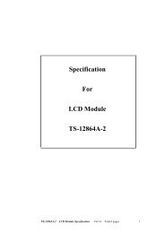
fuel flow to the engine to change the power to maintain the desired angular rate. A<br />
block diagram <strong>of</strong> the rpm governor is shown in figure 3. Further details <strong>of</strong> the<br />
dynamic model <strong>for</strong> this degree <strong>of</strong> freedom and the rpm governor are given in<br />
appendix G.<br />
/ (MAIN AND TAIL ROTOR<br />
4 Q ~ o<br />
THROTTLE TORQUE REQUIRED)<br />
(0 N/O F F )<br />
-Ai2<br />
GOVERNOR<br />
%ET G (SI<br />
=a,<br />
-<br />
s1<br />
A W V<br />
AHP<br />
550 wf An<br />
s2<br />
4<br />
As2<br />
* KE -m - b<br />
Figure 3.- Block diagram <strong>of</strong> rpm governor.<br />
6<br />
+